EP3308140B1 - Method and system of using image capturing device for counterfeit article detection - Google Patents
Method and system of using image capturing device for counterfeit article detection Download PDFInfo
- Publication number
- EP3308140B1 EP3308140B1 EP16812284.4A EP16812284A EP3308140B1 EP 3308140 B1 EP3308140 B1 EP 3308140B1 EP 16812284 A EP16812284 A EP 16812284A EP 3308140 B1 EP3308140 B1 EP 3308140B1
- Authority
- EP
- European Patent Office
- Prior art keywords
- images
- image
- ultraviolet
- infrared
- article
- Prior art date
- Legal status (The legal status is an assumption and is not a legal conclusion. Google has not performed a legal analysis and makes no representation as to the accuracy of the status listed.)
- Active
Links
- 238000000034 method Methods 0.000 title claims description 22
- 238000001514 detection method Methods 0.000 title description 33
- 238000012360 testing method Methods 0.000 claims description 39
- 238000005286 illumination Methods 0.000 claims description 14
- 230000003287 optical effect Effects 0.000 claims description 13
- 238000012545 processing Methods 0.000 claims description 6
- 238000012795 verification Methods 0.000 description 11
- 230000004913 activation Effects 0.000 description 6
- 238000010586 diagram Methods 0.000 description 5
- 230000000007 visual effect Effects 0.000 description 5
- 238000004891 communication Methods 0.000 description 4
- 238000005516 engineering process Methods 0.000 description 3
- 238000004458 analytical method Methods 0.000 description 2
- 230000010354 integration Effects 0.000 description 2
- 238000004519 manufacturing process Methods 0.000 description 2
- 238000009877 rendering Methods 0.000 description 2
- 238000012549 training Methods 0.000 description 2
- 0 CCNC*(C)CO Chemical compound CCNC*(C)CO 0.000 description 1
- 239000011248 coating agent Substances 0.000 description 1
- 238000000576 coating method Methods 0.000 description 1
- 230000007423 decrease Effects 0.000 description 1
- 230000001419 dependent effect Effects 0.000 description 1
- 238000013461 design Methods 0.000 description 1
- 230000000694 effects Effects 0.000 description 1
- 238000000605 extraction Methods 0.000 description 1
- 238000003384 imaging method Methods 0.000 description 1
- 238000007639 printing Methods 0.000 description 1
- 230000005855 radiation Effects 0.000 description 1
- 238000012552 review Methods 0.000 description 1
- 230000007704 transition Effects 0.000 description 1
- 230000007723 transport mechanism Effects 0.000 description 1
Images


Classifications
-
- G—PHYSICS
- G07—CHECKING-DEVICES
- G07D—HANDLING OF COINS OR VALUABLE PAPERS, e.g. TESTING, SORTING BY DENOMINATIONS, COUNTING, DISPENSING, CHANGING OR DEPOSITING
- G07D7/00—Testing specially adapted to determine the identity or genuineness of valuable papers or for segregating those which are unacceptable, e.g. banknotes that are alien to a currency
- G07D7/06—Testing specially adapted to determine the identity or genuineness of valuable papers or for segregating those which are unacceptable, e.g. banknotes that are alien to a currency using wave or particle radiation
- G07D7/12—Visible light, infrared or ultraviolet radiation
- G07D7/128—Viewing devices
-
- G—PHYSICS
- G06—COMPUTING; CALCULATING OR COUNTING
- G06T—IMAGE DATA PROCESSING OR GENERATION, IN GENERAL
- G06T7/00—Image analysis
- G06T7/90—Determination of colour characteristics
-
- G—PHYSICS
- G06—COMPUTING; CALCULATING OR COUNTING
- G06V—IMAGE OR VIDEO RECOGNITION OR UNDERSTANDING
- G06V30/00—Character recognition; Recognising digital ink; Document-oriented image-based pattern recognition
- G06V30/10—Character recognition
- G06V30/24—Character recognition characterised by the processing or recognition method
- G06V30/248—Character recognition characterised by the processing or recognition method involving plural approaches, e.g. verification by template match; Resolving confusion among similar patterns, e.g. "O" versus "Q"
- G06V30/2504—Coarse or fine approaches, e.g. resolution of ambiguities or multiscale approaches
-
- H—ELECTRICITY
- H04—ELECTRIC COMMUNICATION TECHNIQUE
- H04N—PICTORIAL COMMUNICATION, e.g. TELEVISION
- H04N23/00—Cameras or camera modules comprising electronic image sensors; Control thereof
- H04N23/10—Cameras or camera modules comprising electronic image sensors; Control thereof for generating image signals from different wavelengths
- H04N23/11—Cameras or camera modules comprising electronic image sensors; Control thereof for generating image signals from different wavelengths for generating image signals from visible and infrared light wavelengths
-
- H—ELECTRICITY
- H04—ELECTRIC COMMUNICATION TECHNIQUE
- H04N—PICTORIAL COMMUNICATION, e.g. TELEVISION
- H04N23/00—Cameras or camera modules comprising electronic image sensors; Control thereof
- H04N23/56—Cameras or camera modules comprising electronic image sensors; Control thereof provided with illuminating means
-
- H—ELECTRICITY
- H04—ELECTRIC COMMUNICATION TECHNIQUE
- H04N—PICTORIAL COMMUNICATION, e.g. TELEVISION
- H04N23/00—Cameras or camera modules comprising electronic image sensors; Control thereof
- H04N23/80—Camera processing pipelines; Components thereof
- H04N23/84—Camera processing pipelines; Components thereof for processing colour signals
-
- H—ELECTRICITY
- H04—ELECTRIC COMMUNICATION TECHNIQUE
- H04N—PICTORIAL COMMUNICATION, e.g. TELEVISION
- H04N5/00—Details of television systems
- H04N5/30—Transforming light or analogous information into electric information
- H04N5/33—Transforming infrared radiation
-
- G—PHYSICS
- G06—COMPUTING; CALCULATING OR COUNTING
- G06T—IMAGE DATA PROCESSING OR GENERATION, IN GENERAL
- G06T2207/00—Indexing scheme for image analysis or image enhancement
- G06T2207/10—Image acquisition modality
- G06T2207/10004—Still image; Photographic image
- G06T2207/10008—Still image; Photographic image from scanner, fax or copier
-
- G—PHYSICS
- G06—COMPUTING; CALCULATING OR COUNTING
- G06T—IMAGE DATA PROCESSING OR GENERATION, IN GENERAL
- G06T2207/00—Indexing scheme for image analysis or image enhancement
- G06T2207/10—Image acquisition modality
- G06T2207/10024—Color image
-
- G—PHYSICS
- G06—COMPUTING; CALCULATING OR COUNTING
- G06V—IMAGE OR VIDEO RECOGNITION OR UNDERSTANDING
- G06V2201/00—Indexing scheme relating to image or video recognition or understanding
- G06V2201/01—Solutions for problems related to non-uniform document background
Definitions
- Counterfeit article detection by imaging related security devices is critical for preventing use of counterfeit articles, such as counterfeit currency or documents.
- Traditional counterfeit detection relies on a standalone verifier with partial or whole article images displayed on an LCD screen without reference images provided concurrently. Without stored reference images, it is difficult for a cashier, or other person involved with a transaction, even those with substantial training in counterfeit article identification, to make an accurate detection.
- counterfeit currency an added difficulty is that there are currently many different versions of certain currency bills of the same type in circulation.
- Other challenges exist for identification of counterfeit currency in particular including when an active bill, such as a $1 bill (USD), is altered to become a higher value bill. In this case, many of the security features embedded in the original $1 bill are still present and valid, making the counterfeit currency harder to detect. As a result, an improved device, method, and system for counterfeit article detection is needed.
- USD $1 bill
- the device includes an image-capturing component for capturing images of a test article (an article to be verified for authenticity) and a database for storing images of associated authentic or pre-authenticated articles for retrieval and comparison with scanned or captured images of the test article.
- the device may include a scanning or image-capturing component that includes one or more wavelength emitting elements (e.g., red wavelength, infrared wavelength, ultraviolet wavelength, etc.), for illuminating different optical aspects, and the associated security features, of an article to be verified.
- the device may be configured to capture separate images of the article with the different optical aspects highlighted by the different wavelengths emitted at different times.
- the wavelength emitting elements may be controlled and activated independently to allow alternating capture of images of the article with different highlighted visual aspects (e.g., ultra violet security feature illumination, standard visual design, etc.).
- the captured images with differing optical aspects may be communicated to a display portion for display to a user, and the display of the images may occur in alternating fashion to superimpose the different security features into a single image viewable by a user of the device.
- the various images may be captured by a single imager in a single camera chamber of an image capturing device, rather than in multiple chambers each having separate emitting and capturing components segmented into each chamber. This reduces cost of manufacture, decreases the space required for the device, and provides an accurate analytical tool for a user for determining the authenticity of articles or other items, objects, or documents in which embedded light wavelength activated security features are present.
- the device may be configured to receive article-identifying information (e.g., article name, year, etc.), from a user or other source, to locate authentic or pre-authenticated image(s) of the article in the reference image database.
- article identifying information may be a currency date, currency type, currency denomination, currency nationality, or some other currency distinguishing information.
- the input may be received through an input component (e.g., a keyboard, mouse, touch-interface, graphical user-interface, voice-input component, or other data input device), and the article identifying information may be used to retrieve from a reference database one or more reference images of the associated authentic article for display and comparison.
- a display may be provided to display the captured images and the reference images for comparison by a user of the device.
- the display portion providing the captured images may be configured to display in alternating fashion each of the captured images highlighting the different security features (e.g., images under red wavelengths, images under infrared wavelengths, images under ultraviolet wavelengths, etc.) on top of each other to form one superimposed image that shows each of the captured security features in the separate images captured by the image capturing component in the device.
- the superimposed image may then be displayed alongside the reference image of the authentic article for comparison.
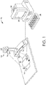
- an exemplary device 10 for counterfeit article detection is provided, in accordance with an aspect of the present invention.
- an image capturing device 12 (which in this exemplary aspect is a scanner) is provided that includes multiple image capturing chambers 14 which can each be fitted with one or more image capturing components 16 and one or more wavelength emitting elements 18 which can be controlled to independently illuminate various security features of a currency test note 20 (the currency note is but one exemplary article for verification with the device 12; others may be verified as well).
- a top-down scanning component 22 is in operation to capture an image of the currency note 20 to be analyzed for counterfeit security features.
- the top-down scanning component 22 includes a window 24 through which multiple wavelength emitting elements (not visible in FIG. 1 ; see FIG. 7 ), which may be Light Emitting Diodes ("LEDs"), can illuminate the currency note 20, and also through which an image may be received and captured by an image capturing component (e.g., imager) which receives the reflected or stimulated wavelengths from the different light emitting elements that illuminate various optical features of the currency note 20.
- the captured images may be transmitted from the scanner 22 to a computing device 26 which may contain a reference database of stored currency images, and other article images, for comparison with the tested currency note 20.
- the computing device 26 may include an input device 28 (shown in FIG. 1 as a keyboard; the input device may alternatively be a touch screen, a graphical user-interface, a touch-pad, etc.) for receiving article identifying information, such as, in the example of currency notes, a year of the currency production (e.g., 2002, 2004, etc.), a nationality or currency zone designation (e.g., euros, yen, USD, etc.), and/or a currency denomination (1, 20, 100, etc.), which may be used for retrieving one or more stored reference images of authentic, or pre-authenticated, currency notes for comparison with the captured images of the currency test note 20.
- the computing device 26 further includes a display 30 for displaying one or more captured images of the currency test note 20 from the image-capturing device 12 and one or more reference images of associated authentic currency images from the stored currency image database.
- FIG. 2 a first displayed currency comparison 32 associated with an image capturing device for counterfeit currency detection is provided, in accordance with an aspect of the present invention.
- a series of reference images 34 of first and second sides of the currency test note 20 is presented on the left side of FIG. 2
- a captured image 36 to be compared with one of the reference images 34 is provided on the right side of FIG. 2 .
- the reference images 34 are retrieved from a reference database containing authentic article images, including authentic currency images associated with the captured image 36, using article identifying information.
- These images 34, 36 may be presented on a display connected to an image capturing device, or on separate displays, or visually in any number of other ways that allow review by a user of the device.
- FIG. 1 a series of reference images 34 of first and second sides of the currency test note 20 is presented on the left side of FIG. 2
- a captured image 36 to be compared with one of the reference images 34 is provided on the right side of FIG. 2 .
- the reference images 34 are retrieved from a reference
- the captured image 36 in FIG. 2 is generated from an infrared wavelength emission and associated image capture by the image-capturing device, to show infrared wavelength visible security features on the currency test note 20.
- the four reference images 34 include a top-down first side first image 38, a top-up first side second image 40, a top-up second side third image 42, and a top-down second side fourth image 42 of an authentic version of the currency test note 20.
- the captured image 36 when compared with the four reference images, matches the third reference image 42.
- a user testing the currency test note need only compare the third image reference image 42 of the currency test note 20 to the captured image 36 for verification.
- the required infrared security features 46 are present on the currency test note 20, as shown by the third reference image 42 and the captured image 36 being the same. If any of the reference images 34 associated with the currency test note 20 do not match the captured image 36, the currency test note 20 may be identified as a potential counterfeit.
- FIG. 3 a second displayed currency comparison 48 associated with an image-capturing device for counterfeit article detection is provided, in accordance with an aspect of the present invention.
- a similar comparison as FIG. 2 is provided, with reference images 50 on the left, and an associated captured image 52 on the right.
- the reference images 50 of the currency note to be verified include images of the first and second sides of the note, and specifically, the reference images 50 include a top-up first side first image 54 and a top-down first side second image 56 of the currency note.
- the captured image 52 corresponds to the second image 56 of the reference images 50.
- the captured image 52 is captured while the note is under illumination from ultraviolet emitting elements in an image-capturing device.
- the reflected ultraviolet wavelengths provide illumination of the ultraviolet visible security features 58, for comparison with the reference images 50. This clearly shows the proper ultraviolet security features 58.
- the captured image 52 in FIG. 3 features the same illuminated security features 58 as the reference images 50, which are visible under ultraviolet light. As with FIG. 2 , if the captured image 52 associated with the currency test note images 50 does not match one of the reference images 50, the currency test note may be identified as a potential counterfeit. In this respect, because a clear visual comparison of the illuminated security features is possible, minimal training and/or technological understanding is required for a user attempting to identify counterfeit currency with the device.
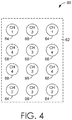
- an exemplary configuration 60 of multiple light emitting elements which are positioned in a single image capturing device for counterfeit article detection is provided, in accordance with an aspect of the present invention.
- three different wavelength emitting elements which may in one aspect be LEDs, are organized in a single chamber of an image capturing device for use in providing illumination of a currency test note under different wavelengths.
- a wavelength emitting element mount 62 is provided for organizing the multiple wavelength emitting elements.
- the elements include first red wavelength emitting elements (CH1/CH2) 64, second infrared wavelength emitting elements (CH3) 66, and third ultraviolet wavelength emitting elements (CH4) 68.
- the first emitting elements 64 may correspond to the red wavelength optical range (e.g., a 660 nanometer (nm) wavelength) for barcode reading
- the second emitting elements 66 may correspond to an infrared wavelength optical range (e.g., 850 nm wavelength)
- the third emitting elements 68 may correspond to an ultraviolet wavelength optical range (e.g., 365 nm wavelength).
- Multiple configurations of the light emitting elements 64, 66, 68 on the mount 62, as well as different numbers and ratios of the light emitting elements 64, 66, 68, are possible, allowing various illumination options for articles towards which the image capturing device is directed for article authenticity verification.
- FIG. 5 an exemplary computing environment for an image-capturing device for counterfeit article detection is provided, in accordance with an aspect of the present invention.
- an exemplary operating environment for implementing embodiments described herein is shown and designated generally as computing device 500.
- Computing device 500 is but one example of a suitable computing environment and is not intended to suggest any limitation as to the scope of use or functionality of the invention. Neither should the computing device 500 be interpreted as having any dependency or requirement relating to any one or combination of components illustrated.
- the invention may be described in the general context of computer code or machine-useable instructions, including computer-executable instructions such as program modules, being executed by a computer or other machine, such as a personal data assistant or other handheld device.
- program modules including routines, programs, objects, components, data structures, etc. refer to code that perform particular tasks or implement particular abstract data types.
- the invention may be practiced in a variety of system configurations, including hand-held devices, consumer electronics, general-purpose computers, more specialty computing devices, etc.
- the invention may also be practiced in distributed computing environments where tasks are performed by remote-processing devices that are linked through a communications network.
- computing device 500 includes a bus 510 that directly or indirectly couples the following devices: memory 512, one or more processors 514, one or more presentation components 516, input/output ports 518, input/output components 520, and an illustrative power supply 522.
- Bus 510 represents what may be one or more busses (such as an address bus, data bus, or combination thereof).
- busses such as an address bus, data bus, or combination thereof.
- FIG. 5 is merely illustrative of an exemplary computing device that can be used in connection with one or more embodiments of the present invention. Distinction is not made between such categories as “workstation,” “server,” “laptop,” “hand-held device,” etc., as all are contemplated as within the scope of FIG. 5 and when referencing the "computing device.”
- Computing device 500 typically includes a variety of computer-readable media and/or computer storage media.
- Computer-readable media can be any available media that can be accessed by computing device 500 and includes both volatile and nonvolatile media, removable and non-removable media.
- Computer-readable media may comprise computer storage media and communication media and/or devices.
- Computer storage media may include volatile and nonvolatile, removable and non-removable media implemented in any method or technology for storage of information such as computer-readable instructions, data structures, program modules, or other data.
- Computer storage media includes, but is not limited to, RAM, ROM, EEPROM, flash memory or other memory technology, CD-ROM, digital versatile disks (DVD) or other optical disk storage, magnetic cassettes, magnetic tape, magnetic disk storage or other magnetic storage devices, or any other medium which can be used to store the desired information and which can be accessed by computing device 100.
- Computer storage media does not include signals per se.
- Communication media typically embodies computer-readable instructions, data structures, program modules or other data in a modulated data signal such as a carrier wave or other transport mechanism and includes any information delivery media.
- modulated data signal means a signal that has one or more of its characteristics set or changed in such a manner as to encode information in the signal.
- communication media includes wired media such as a wired network or direct-wired connection, and wireless media such as acoustic, RF, infrared, and other wireless media. Combinations of any of the above should also be included within the scope of computer-readable media.
- Memory 512 includes computer storage media in the form of volatile and/or nonvolatile memory.
- the memory may be removable, non-removable, or a combination thereof.
- Exemplary hardware devices include solid-state memory, hard drives, optical-disc drives, etc.
- Computing device 500 includes one or more processors that read data from various entities such as memory 512 or I/O components 520.
- Presentation component(s) 516 present data indications to a user or other device.
- Exemplary presentation components include a display device, speaker, printing component, vibrating component, etc.
- I/O ports 518 allow computing device 500 to be logically coupled to other devices including I/O components 520, some of which may be built in.
- Illustrative components include a microphone, joystick, game pad, satellite dish, scanner, printer, wireless device, and the like.
- a first graphical representation 70 of the capturing and processing of images with an image capturing device for counterfeit article detection is provided, in accordance with an aspect of the present invention.
- the timing of image-capture and rendering for article analysis is depicted in a series of sub-graphical representations 74, 78, 82, 86.
- a time axis 72 is provided along a bottom of the graphical representation 70 to show the passage of time relative to the activity on each of the sub-graphical representations 74, 78, 82, 86.
- the first sub-graphical representation 74 is provided for indicating a timing of activation of infrared emitting elements (which in this case are identified as infrared LEDs).
- the blocks 76 indicate the times at which the infrared LEDs are illuminated for providing an infrared wavelength based illumination of an article for capture by the image capture device.
- a second sub-graphical representation 78 is provided for indicating a timing of activation of ultraviolet emitting elements (which in this case are ultraviolet LEDs).
- the blocks 80 indicate the times at which the ultraviolet LEDs are illuminated for providing an ultraviolet wavelength based illumination of an article for user visual verification.
- a third sub-graphical representation 82 is provided for showing integration of the images for presentation to a user of the device.
- the blocks 84 indicate the times at which the image is integrated, which in FIG. 6 , is only at the times corresponding to the infrared emissions.
- a fourth sub-graphical representation 86 is provided for showing the rendered infrared image data for presentation to a viewer, with blocks 88 corresponding to the time periods for presenting the rendered image data readout.
- FIG. 7 an exemplary optical arrangement 90 of an image-capturing device for counterfeit article detection is provided, in accordance with an aspect of the present invention.
- an image capturing chamber 92 is depicted capturing an image of a currency test note 94 on a surface.
- the image capturing chamber 92 includes an imager 96 for generating images from optical wavelengths received in the image capturing chamber 92, a lens 98, an optical long pass filter 100 (which may be a coating on the lens 98) to stop ultraviolet to the imager 96 to increase image contrast of security features under ultraviolet illumination since the ultraviolet security features are color visible light radiation stimulated by ultraviolet light, a first grouping of wavelength emitting elements 102 (e.g., LEDs), a second grouping of wavelength emitting elements 104, and a window 106.
- a first grouping of wavelength emitting elements 102 e.g., LEDs
- the wavelength emitting elements 102, 104 which may produce distinct and separate wavelengths (red, infrared, ultraviolet, etc.), may be activated in an alternating or separated fashion (e.g., infrared wavelengths may be emitted from elements 102 along with an associated infrared image capture by the imager 96, and subsequently ultraviolet wavelengths may be emitted from elements 104 along with an associated ultraviolet image capture by the imager 96, etc.).
- the imager 96 captures the separate images generated by the emitted wavelengths reflected from the currency test note 94, a rapidly generated series of images with different illuminated properties may be provided to a computing device for superimposing to generate a consolidated image showing all of the security features highlighted for comparison against an authentic associated currency image.
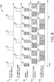
- FIG. 8 a second graphical representation 108 of the capturing and presenting of images with an image capturing device for counterfeit article detection is provided, in accordance with an aspect of the present invention.
- FIG. 8 the timing of image capture and rendering of images for article analysis is depicted.
- a time axis 72 is provided along a bottom of the graph 108 in FIG. 8 .
- a first sub-graphical representation 74 is provided for indicating a timing of activation of infrared emitting elements (which in this case are identified as infrared LEDs).
- the blocks 76 indicate the times at which the infrared LEDs are illuminated for providing an infrared wavelength based illumination of a currency test note for capture by the image capture device.
- a second sub-graphical representation 78 is provided for indicating a timing of activation of ultraviolet emitting elements (which in this case are identified as ultraviolet LEDs).
- the blocks 80 indicate the times at which the ultraviolet LEDs are illuminated for providing an ultraviolet wavelength based illumination of an object for capture by an image capturing device and user visual verification.
- a third sub-graphical representation 82 is provided for showing integration of the images for presentation.
- the blocks 84, 85 indicate the times at which the image is integrated, which in FIG. 8 , is both of the times corresponding to the infrared emissions 84 and also the ultraviolet emissions 85, such that both the infrared and the ultraviolet emissions 84, 85 are integrated.
- a fourth sub-graphical representation 110 is provided for showing the timing of the capture of infrared images and ultraviolet images, which occur at separate times, as shown by infrared image capture blocks 112 and ultraviolet image capture blocks 114. By capturing the images at different times in alternating fashion, two images illuminating separate security features may be produced from the same image capturing device.
- a fifth sub-graphical representation 116 is provided for showing the timing and combination of the captured infrared and ultraviolet images for display at selected infrared time blocks 118 and ultraviolet time blocks 120. The images may be captured, and alternated, to present the alternating images at a frame rate of 25-80 frames per second (e.g., 80 frames per second with 40 frames of infrared images and 40 frames of ultraviolet images alternated with each other).
- FIG. 9 a block diagram 900 of an exemplary method of using a scanner for counterfeit article detection is provided, in accordance with an aspect of the present invention.
- article-identifying information associated with a test article such as year and/or denomination for a currency note if a currency note is being tested.
- one or more comparison images of an authentic article associated with the test article are received from an image storage database.
- the test article is scanned to capture one or more test images of the test article.
- the one or more test images and the one or more comparison images are provided for display.
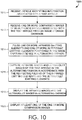
- FIG. 10 a block diagram 1000 of an exemplary method of using an image capturing device for counterfeit article detection is provided, in accordance with an aspect of the present invention.
- article-identifying information associated with a test article is received.
- one or more comparison images of an authentic article associated with the test article are received from an image storage database.
- one or more infrared emitting elements and one or more ultraviolet emitting elements positioned in the image capturing device are pulsed in an alternating fashion.
- infrared images and ultraviolet images of the test article are captured in the alternating fashion in accordance with the respective pulsing of the infrared emitting elements and the ultraviolet emitting elements.
- the infrared images and the ultraviolet images are displayed in alternating fashion.
- at least one of the one or more comparison images are displayed.
- a cashier or user of the scanner/ICD may use the scanner or the ICD in the standard scanning or capturing mode, and begin the currency verification process by setting the barcode scanner/ICD to article identification and/or verification mode.
- the scanner/ICD may receive an input indicating activation of article verification mode through a button input, host command input, or other activation input.
- the blocks of FIGS. 9 and 10 as well as other steps for article verification and determination of authenticity of the test article against pre-authenticated articles via stored authentic article images, may be utilized.
- an input may be received (e.g., button, host command, etc.) to return the scanner/ICD to normal scanning and/or image capturing mode. This transition may also occur after a pre-determined amount of time.
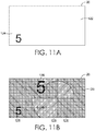
- FIGS. 11A and 11B multiple images of a currency note 20 are provided with various security features illuminated.
- a monochrome/infrared image 122 of the currency note 20 produced by an image capturing device for counterfeit article detection is provided, in accordance with an aspect of the present invention.
- the monochrome/infrared image 122 includes an illuminated infrared security feature 124 (the number "5") which may be compared against an image of an authentic bill with the same security feature highlighted.
- an ultraviolet image 126 of the currency note 20 produced by the image capturing device for counterfeit article detection is provided, in accordance with an aspect of the present invention.
- the ultraviolet image 126 includes illuminated ultraviolet security features 128 which may be compared against a note that is authentic with the same security features highlighted.
- an exemplary system 130 for counterfeit article detection is provided, in accordance with an aspect of the present invention.
- the system 130 is depicted including an image capturing device 132, which may be the scanner depicted in FIG. 1 , that includes an infrared image capturing component 134 and an ultraviolet image capturing component 136.
- An input device 138 which may be a keyboard, touch screen, or other digital or hardware interface, is also provided.
- An image storage database 140 is provided, which may be used to store and retrieve authentic article images (e.g., currency note images, check images, documents images, object images, etc.) for comparison with test articles for which images are captured by the image-capturing device 132.
- authentic article images e.g., currency note images, check images, documents images, object images, etc.
- a display device 142 is provided for displaying one or more test article images captured with the infrared component and/or the ultraviolet component, and also for displaying the authentic article images.
- a point-of-sale (POS) device 144 is provided, at which a sale or a transaction may occur.
Description
- Counterfeit article detection by imaging related security devices is critical for preventing use of counterfeit articles, such as counterfeit currency or documents. Traditional counterfeit detection relies on a standalone verifier with partial or whole article images displayed on an LCD screen without reference images provided concurrently. Without stored reference images, it is difficult for a cashier, or other person involved with a transaction, even those with substantial training in counterfeit article identification, to make an accurate detection. With regard to counterfeit currency, an added difficulty is that there are currently many different versions of certain currency bills of the same type in circulation. Other challenges exist for identification of counterfeit currency in particular, including when an active bill, such as a $1 bill (USD), is altered to become a higher value bill. In this case, many of the security features embedded in the original $1 bill are still present and valid, making the counterfeit currency harder to detect. As a result, an improved device, method, and system for counterfeit article detection is needed.
- From the European patent
application publication EP 1 293 927 A2 a method of detecting a counterfeit article according to the precharacterizing part ofclaim 1 and a corresponding system for detecting counterfeit articles is known. - Further, from the United States patent application publication
US 2012/163697 A1 a method and a system relating to currency or note processing with data recognition is known that may assist in identification of counterfeit notes. - Further, from the United States patent publication
US 7 187 795 B2 an authentication system for detecting counterfeit currency bills is known, which provides for extraction of identification characteristics of the bill to be processed. The extracted characteristics are compared to data of known counterfeit bills, stored in a database. - It is an object to provide a method and system for counterfeit article detection. This and other objects are achieved by a method of detecting a counterfeit article according to
claim 1 and the corresponding system for detecting counterfeit articles. Advantageous further embodiments are claimed in the dependent claims. - Illustrative embodiments of the present invention are described in detail below with reference to the attached drawing figures, wherein:
-
FIG. 1 is an exemplary device for counterfeit article detection, in accordance with an aspect of the present invention; -
FIG. 2 is an example of a first displayed currency comparison associated with an image capturing device for counterfeit article detection, in accordance with an aspect of the present invention; -
FIG. 3 is an example of a second displayed currency comparison associated with an image capturing device for counterfeit article detection, in accordance with an aspect of the present invention; -
FIG. 4 is an exemplary configuration of multiple wavelength emitting elements which are positioned in a single image capturing device for counterfeit article detection, in accordance with an aspect of the present invention; -
FIG. 5 is an exemplary computing environment associated with an image capturing device for counterfeit article detection, in accordance with an aspect of the present invention; -
FIG. 6 is a first graphical representation of the capturing and processing of images with an image capturing device for counterfeit article detection, in accordance with an aspect of the present invention; -
FIG. 7 is an exemplary optical arrangement of an image capturing device for counterfeit article detection, in accordance with an aspect of the present invention; -
FIG. 8 is a second graphical representation of capturing and processing of images with an image capturing device for counterfeit article detection, in accordance with an aspect of the present invention; -
FIG. 9 is a block diagram of an exemplary method of using a scanner for counterfeit article detection, in accordance with an aspect of the present invention; -
FIG. 10 is a block diagram of an exemplary method of using an image capturing device for counterfeit article detection, in accordance with an aspect of the present invention; -
FIG. 11A is a monochrome/infrared image under infrared illumination of a currency note produced by an image capturing device for counterfeit article detection, in accordance with an aspect of the present invention; -
FIG. 11B is an image under ultraviolet illumination of the currency note ofFIG. 11A produced by an image capturing device for counterfeit article detection, in accordance with an aspect of the present invention; and -
FIG. 12 is an exemplary system for counterfeit article detection, in accordance with an aspect of the present invention. - The subject matter of aspects of the present invention is described with specificity herein to meet statutory requirements. However, the description itself is not intended to limit the scope of the claims. Rather, the claimed subject matter might be embodied in other ways to include different elements or combinations of elements, Terms should not be interpreted as implying any particular order among or between various steps disclosed unless and except when the order of individual steps is explicitly described.
- In a broad aspect, a method according to
claim 1 and system according to claim 8 for counterfeit article detection are provided. Generally, the device includes an image-capturing component for capturing images of a test article (an article to be verified for authenticity) and a database for storing images of associated authentic or pre-authenticated articles for retrieval and comparison with scanned or captured images of the test article. The device may include a scanning or image-capturing component that includes one or more wavelength emitting elements (e.g., red wavelength, infrared wavelength, ultraviolet wavelength, etc.), for illuminating different optical aspects, and the associated security features, of an article to be verified. The device may be configured to capture separate images of the article with the different optical aspects highlighted by the different wavelengths emitted at different times. In this regard, the wavelength emitting elements may be controlled and activated independently to allow alternating capture of images of the article with different highlighted visual aspects (e.g., ultra violet security feature illumination, standard visual design, etc.). The captured images with differing optical aspects may be communicated to a display portion for display to a user, and the display of the images may occur in alternating fashion to superimpose the different security features into a single image viewable by a user of the device. In this respect, the various images may be captured by a single imager in a single camera chamber of an image capturing device, rather than in multiple chambers each having separate emitting and capturing components segmented into each chamber. This reduces cost of manufacture, decreases the space required for the device, and provides an accurate analytical tool for a user for determining the authenticity of articles or other items, objects, or documents in which embedded light wavelength activated security features are present. - In additional aspects, the device may be configured to receive article-identifying information (e.g., article name, year, etc.), from a user or other source, to locate authentic or pre-authenticated image(s) of the article in the reference image database. In the example of a currency note, the article identifying information may be a currency date, currency type, currency denomination, currency nationality, or some other currency distinguishing information. The input may be received through an input component (e.g., a keyboard, mouse, touch-interface, graphical user-interface, voice-input component, or other data input device), and the article identifying information may be used to retrieve from a reference database one or more reference images of the associated authentic article for display and comparison. A display may be provided to display the captured images and the reference images for comparison by a user of the device. The display portion providing the captured images may be configured to display in alternating fashion each of the captured images highlighting the different security features (e.g., images under red wavelengths, images under infrared wavelengths, images under ultraviolet wavelengths, etc.) on top of each other to form one superimposed image that shows each of the captured security features in the separate images captured by the image capturing component in the device. The superimposed image may then be displayed alongside the reference image of the authentic article for comparison.
- Referring now to
FIG. 1 , anexemplary device 10 for counterfeit article detection is provided, in accordance with an aspect of the present invention. InFIG. 1 , an image capturing device 12 (which in this exemplary aspect is a scanner) is provided that includes multipleimage capturing chambers 14 which can each be fitted with one or moreimage capturing components 16 and one or morewavelength emitting elements 18 which can be controlled to independently illuminate various security features of a currency test note 20 (the currency note is but one exemplary article for verification with thedevice 12; others may be verified as well). In this respect, there aremultiple chambers 14 at which the article illumination and image capture may occur, although thedevice 10 may be configured to allow all image capturing to occur through one selected chamber, as discussed herein. As shown inFIG. 1 , a top-down scanning component 22 is in operation to capture an image of thecurrency note 20 to be analyzed for counterfeit security features. The top-down scanning component 22 includes awindow 24 through which multiple wavelength emitting elements (not visible inFIG. 1 ; seeFIG. 7 ), which may be Light Emitting Diodes ("LEDs"), can illuminate thecurrency note 20, and also through which an image may be received and captured by an image capturing component (e.g., imager) which receives the reflected or stimulated wavelengths from the different light emitting elements that illuminate various optical features of thecurrency note 20. The captured images may be transmitted from thescanner 22 to acomputing device 26 which may contain a reference database of stored currency images, and other article images, for comparison with the testedcurrency note 20. - As shown in
FIG. 1 , thecomputing device 26 may include an input device 28 (shown inFIG. 1 as a keyboard; the input device may alternatively be a touch screen, a graphical user-interface, a touch-pad, etc.) for receiving article identifying information, such as, in the example of currency notes, a year of the currency production (e.g., 2002, 2004, etc.), a nationality or currency zone designation (e.g., euros, yen, USD, etc.), and/or a currency denomination (1, 20, 100, etc.), which may be used for retrieving one or more stored reference images of authentic, or pre-authenticated, currency notes for comparison with the captured images of thecurrency test note 20. Thecomputing device 26 further includes adisplay 30 for displaying one or more captured images of thecurrency test note 20 from the image-capturingdevice 12 and one or more reference images of associated authentic currency images from the stored currency image database. - Referring now to
FIG. 2 , a first displayedcurrency comparison 32 associated with an image capturing device for counterfeit currency detection is provided, in accordance with an aspect of the present invention. InFIG. 2 , a series ofreference images 34 of first and second sides of thecurrency test note 20 is presented on the left side ofFIG. 2 , and a capturedimage 36 to be compared with one of thereference images 34 is provided on the right side ofFIG. 2 . Thereference images 34 are retrieved from a reference database containing authentic article images, including authentic currency images associated with the capturedimage 36, using article identifying information. Theseimages FIG. 2 , one or more capturedimages 36 of the currency test note are presented for comparison with thereference images 34. The capturedimage 36 inFIG. 2 is generated from an infrared wavelength emission and associated image capture by the image-capturing device, to show infrared wavelength visible security features on thecurrency test note 20. The fourreference images 34 include a top-down first sidefirst image 38, a top-up first sidesecond image 40, a top-up second sidethird image 42, and a top-down second sidefourth image 42 of an authentic version of thecurrency test note 20. The capturedimage 36, when compared with the four reference images, matches thethird reference image 42. Thus, a user testing the currency test note need only compare the thirdimage reference image 42 of thecurrency test note 20 to the capturedimage 36 for verification. As shown, with this being an infrared wavelength illuminated feature comparison, the required infrared security features 46 are present on thecurrency test note 20, as shown by thethird reference image 42 and the capturedimage 36 being the same. If any of thereference images 34 associated with thecurrency test note 20 do not match the capturedimage 36, thecurrency test note 20 may be identified as a potential counterfeit. - Referring now to
FIG. 3 , a second displayedcurrency comparison 48 associated with an image-capturing device for counterfeit article detection is provided, in accordance with an aspect of the present invention. InFIG. 3 , a similar comparison asFIG. 2 is provided, withreference images 50 on the left, and an associated capturedimage 52 on the right. Thereference images 50 of the currency note to be verified include images of the first and second sides of the note, and specifically, thereference images 50 include a top-up first sidefirst image 54 and a top-down first sidesecond image 56 of the currency note. The capturedimage 52 corresponds to thesecond image 56 of thereference images 50. The capturedimage 52 is captured while the note is under illumination from ultraviolet emitting elements in an image-capturing device. The reflected ultraviolet wavelengths provide illumination of the ultraviolet visible security features 58, for comparison with thereference images 50. This clearly shows the proper ultraviolet security features 58. The capturedimage 52 inFIG. 3 features the same illuminated security features 58 as thereference images 50, which are visible under ultraviolet light. As withFIG. 2 , if the capturedimage 52 associated with the currencytest note images 50 does not match one of thereference images 50, the currency test note may be identified as a potential counterfeit. In this respect, because a clear visual comparison of the illuminated security features is possible, minimal training and/or technological understanding is required for a user attempting to identify counterfeit currency with the device. - Referring now to
FIG. 4 , anexemplary configuration 60 of multiple light emitting elements which are positioned in a single image capturing device for counterfeit article detection is provided, in accordance with an aspect of the present invention. In the exemplary configuration shown inFIG. 4 , three different wavelength emitting elements, which may in one aspect be LEDs, are organized in a single chamber of an image capturing device for use in providing illumination of a currency test note under different wavelengths. InFIG. 4 , a wavelength emitting element mount 62 is provided for organizing the multiple wavelength emitting elements. The elements include first red wavelength emitting elements (CH1/CH2) 64, second infrared wavelength emitting elements (CH3) 66, and third ultraviolet wavelength emitting elements (CH4) 68. In this regard, the first emittingelements 64 may correspond to the red wavelength optical range (e.g., a 660 nanometer (nm) wavelength) for barcode reading, the second emittingelements 66 may correspond to an infrared wavelength optical range (e.g., 850 nm wavelength), and the third emittingelements 68 may correspond to an ultraviolet wavelength optical range (e.g., 365 nm wavelength). Multiple configurations of thelight emitting elements light emitting elements - Referring now to
FIG. 5 , an exemplary computing environment for an image-capturing device for counterfeit article detection is provided, in accordance with an aspect of the present invention. InFIG. 5 , an exemplary operating environment for implementing embodiments described herein is shown and designated generally ascomputing device 500.Computing device 500 is but one example of a suitable computing environment and is not intended to suggest any limitation as to the scope of use or functionality of the invention. Neither should thecomputing device 500 be interpreted as having any dependency or requirement relating to any one or combination of components illustrated. - The invention may be described in the general context of computer code or machine-useable instructions, including computer-executable instructions such as program modules, being executed by a computer or other machine, such as a personal data assistant or other handheld device. Generally, program modules including routines, programs, objects, components, data structures, etc. refer to code that perform particular tasks or implement particular abstract data types. The invention may be practiced in a variety of system configurations, including hand-held devices, consumer electronics, general-purpose computers, more specialty computing devices, etc. The invention may also be practiced in distributed computing environments where tasks are performed by remote-processing devices that are linked through a communications network.
- With reference to
FIG. 5 ,computing device 500 includes abus 510 that directly or indirectly couples the following devices:memory 512, one ormore processors 514, one ormore presentation components 516, input/output ports 518, input/output components 520, and anillustrative power supply 522.Bus 510 represents what may be one or more busses (such as an address bus, data bus, or combination thereof). Although the various blocks ofFIG. 5 are shown with lines for the sake of clarity, in reality, delineating various components is not as clear, and metaphorically, the lines are blurred. For example, one may consider a presentation component such as a display device to be an I/O component. Also, processors have memory. The diagram ofFIG. 5 is merely illustrative of an exemplary computing device that can be used in connection with one or more embodiments of the present invention. Distinction is not made between such categories as "workstation," "server," "laptop," "hand-held device," etc., as all are contemplated as within the scope ofFIG. 5 and when referencing the "computing device." -
Computing device 500 typically includes a variety of computer-readable media and/or computer storage media. Computer-readable media can be any available media that can be accessed by computingdevice 500 and includes both volatile and nonvolatile media, removable and non-removable media. By way of example, and not limitation, computer-readable media may comprise computer storage media and communication media and/or devices. Computer storage media may include volatile and nonvolatile, removable and non-removable media implemented in any method or technology for storage of information such as computer-readable instructions, data structures, program modules, or other data. Computer storage media includes, but is not limited to, RAM, ROM, EEPROM, flash memory or other memory technology, CD-ROM, digital versatile disks (DVD) or other optical disk storage, magnetic cassettes, magnetic tape, magnetic disk storage or other magnetic storage devices, or any other medium which can be used to store the desired information and which can be accessed by computingdevice 100. Computer storage media does not include signals per se. - Communication media typically embodies computer-readable instructions, data structures, program modules or other data in a modulated data signal such as a carrier wave or other transport mechanism and includes any information delivery media. The term "modulated data signal" means a signal that has one or more of its characteristics set or changed in such a manner as to encode information in the signal. By way of example, and not limitation, communication media includes wired media such as a wired network or direct-wired connection, and wireless media such as acoustic, RF, infrared, and other wireless media. Combinations of any of the above should also be included within the scope of computer-readable media.
-
Memory 512 includes computer storage media in the form of volatile and/or nonvolatile memory. The memory may be removable, non-removable, or a combination thereof. Exemplary hardware devices include solid-state memory, hard drives, optical-disc drives, etc.Computing device 500 includes one or more processors that read data from various entities such asmemory 512 or I/O components 520. Presentation component(s) 516 present data indications to a user or other device. Exemplary presentation components include a display device, speaker, printing component, vibrating component, etc. I/O ports 518 allowcomputing device 500 to be logically coupled to other devices including I/O components 520, some of which may be built in. Illustrative components include a microphone, joystick, game pad, satellite dish, scanner, printer, wireless device, and the like. - Referring now to
FIG. 6 , a firstgraphical representation 70 of the capturing and processing of images with an image capturing device for counterfeit article detection is provided, in accordance with an aspect of the present invention. InFIG. 6 , the timing of image-capture and rendering for article analysis is depicted in a series ofsub-graphical representations time axis 72 is provided along a bottom of thegraphical representation 70 to show the passage of time relative to the activity on each of thesub-graphical representations FIG. 6 , the firstsub-graphical representation 74 is provided for indicating a timing of activation of infrared emitting elements (which in this case are identified as infrared LEDs). Theblocks 76 indicate the times at which the infrared LEDs are illuminated for providing an infrared wavelength based illumination of an article for capture by the image capture device. A secondsub-graphical representation 78 is provided for indicating a timing of activation of ultraviolet emitting elements (which in this case are ultraviolet LEDs). Theblocks 80 indicate the times at which the ultraviolet LEDs are illuminated for providing an ultraviolet wavelength based illumination of an article for user visual verification. A thirdsub-graphical representation 82 is provided for showing integration of the images for presentation to a user of the device. Theblocks 84 indicate the times at which the image is integrated, which inFIG. 6 , is only at the times corresponding to the infrared emissions. A fourthsub-graphical representation 86 is provided for showing the rendered infrared image data for presentation to a viewer, withblocks 88 corresponding to the time periods for presenting the rendered image data readout. - Referring now to
FIG. 7 , an exemplaryoptical arrangement 90 of an image-capturing device for counterfeit article detection is provided, in accordance with an aspect of the present invention. InFIG. 7 , animage capturing chamber 92 is depicted capturing an image of acurrency test note 94 on a surface. Theimage capturing chamber 92 includes animager 96 for generating images from optical wavelengths received in theimage capturing chamber 92, alens 98, an optical long pass filter 100 (which may be a coating on the lens 98) to stop ultraviolet to theimager 96 to increase image contrast of security features under ultraviolet illumination since the ultraviolet security features are color visible light radiation stimulated by ultraviolet light, a first grouping of wavelength emitting elements 102 (e.g., LEDs), a second grouping ofwavelength emitting elements 104, and awindow 106. Thewavelength emitting elements elements 102 along with an associated infrared image capture by theimager 96, and subsequently ultraviolet wavelengths may be emitted fromelements 104 along with an associated ultraviolet image capture by theimager 96, etc.). As thewavelength emitting elements imager 96 captures the separate images generated by the emitted wavelengths reflected from thecurrency test note 94, a rapidly generated series of images with different illuminated properties may be provided to a computing device for superimposing to generate a consolidated image showing all of the security features highlighted for comparison against an authentic associated currency image. - Referring now to
FIG. 8 , a secondgraphical representation 108 of the capturing and presenting of images with an image capturing device for counterfeit article detection is provided, in accordance with an aspect of the present invention. InFIG. 8 , the timing of image capture and rendering of images for article analysis is depicted. Atime axis 72 is provided along a bottom of thegraph 108 inFIG. 8 . Additionally, a firstsub-graphical representation 74 is provided for indicating a timing of activation of infrared emitting elements (which in this case are identified as infrared LEDs). Theblocks 76 indicate the times at which the infrared LEDs are illuminated for providing an infrared wavelength based illumination of a currency test note for capture by the image capture device. A secondsub-graphical representation 78 is provided for indicating a timing of activation of ultraviolet emitting elements (which in this case are identified as ultraviolet LEDs). Theblocks 80 indicate the times at which the ultraviolet LEDs are illuminated for providing an ultraviolet wavelength based illumination of an object for capture by an image capturing device and user visual verification. A thirdsub-graphical representation 82 is provided for showing integration of the images for presentation. Theblocks FIG. 8 , is both of the times corresponding to theinfrared emissions 84 and also theultraviolet emissions 85, such that both the infrared and theultraviolet emissions sub-graphical representation 110 is provided for showing the timing of the capture of infrared images and ultraviolet images, which occur at separate times, as shown by infrared image capture blocks 112 and ultraviolet image capture blocks 114. By capturing the images at different times in alternating fashion, two images illuminating separate security features may be produced from the same image capturing device. A fifthsub-graphical representation 116 is provided for showing the timing and combination of the captured infrared and ultraviolet images for display at selected infrared time blocks 118 and ultraviolet time blocks 120. The images may be captured, and alternated, to present the alternating images at a frame rate of 25-80 frames per second (e.g., 80 frames per second with 40 frames of infrared images and 40 frames of ultraviolet images alternated with each other). - Referring now to
FIG. 9 , a block diagram 900 of an exemplary method of using a scanner for counterfeit article detection is provided, in accordance with an aspect of the present invention. InFIG. 9 , at afirst block 910, article-identifying information associated with a test article, such as year and/or denomination for a currency note if a currency note is being tested, is received. At asecond block 912, one or more comparison images of an authentic article associated with the test article are received from an image storage database. At athird block 914, the test article is scanned to capture one or more test images of the test article. At afourth block 916, the one or more test images and the one or more comparison images are provided for display. - Referring now to
FIG. 10 , a block diagram 1000 of an exemplary method of using an image capturing device for counterfeit article detection is provided, in accordance with an aspect of the present invention. InFIG. 10 , at afirst block 1010, article-identifying information associated with a test article is received. At asecond block 1012, one or more comparison images of an authentic article associated with the test article are received from an image storage database. At athird block 1014, one or more infrared emitting elements and one or more ultraviolet emitting elements positioned in the image capturing device are pulsed in an alternating fashion. At afourth block 1016, infrared images and ultraviolet images of the test article are captured in the alternating fashion in accordance with the respective pulsing of the infrared emitting elements and the ultraviolet emitting elements. At afifth block 1018, the infrared images and the ultraviolet images are displayed in alternating fashion. At asixth block 1020, at least one of the one or more comparison images are displayed. - In additional embodiments, when the device is incorporated into a barcode scanner or ICD to provide article verification capability for the barcode scanner or ICD, a cashier or user of the scanner/ICD may use the scanner or the ICD in the standard scanning or capturing mode, and begin the currency verification process by setting the barcode scanner/ICD to article identification and/or verification mode. In this regard, the scanner/ICD may receive an input indicating activation of article verification mode through a button input, host command input, or other activation input. The blocks of
FIGS. 9 and10 , as well as other steps for article verification and determination of authenticity of the test article against pre-authenticated articles via stored authentic article images, may be utilized. Additionally, at the conclusion of the article verification, an input may be received (e.g., button, host command, etc.) to return the scanner/ICD to normal scanning and/or image capturing mode. This transition may also occur after a pre-determined amount of time. - Referring now to
FIGS. 11A and 11B , multiple images of acurrency note 20 are provided with various security features illuminated. InFIG. 11A , a monochrome/infrared image 122 of thecurrency note 20 produced by an image capturing device for counterfeit article detection is provided, in accordance with an aspect of the present invention. The monochrome/infrared image 122 includes an illuminated infrared security feature 124 (the number "5") which may be compared against an image of an authentic bill with the same security feature highlighted. InFIG. 11B , anultraviolet image 126 of thecurrency note 20 produced by the image capturing device for counterfeit article detection is provided, in accordance with an aspect of the present invention. Theultraviolet image 126 includes illuminated ultraviolet security features 128 which may be compared against a note that is authentic with the same security features highlighted. - Referring now to
FIG. 12 , anexemplary system 130 for counterfeit article detection is provided, in accordance with an aspect of the present invention. InFIG. 12 , thesystem 130 is depicted including animage capturing device 132, which may be the scanner depicted inFIG. 1 , that includes an infraredimage capturing component 134 and an ultravioletimage capturing component 136. Aninput device 138, which may be a keyboard, touch screen, or other digital or hardware interface, is also provided. Animage storage database 140 is provided, which may be used to store and retrieve authentic article images (e.g., currency note images, check images, documents images, object images, etc.) for comparison with test articles for which images are captured by the image-capturingdevice 132. Additionally, adisplay device 142 is provided for displaying one or more test article images captured with the infrared component and/or the ultraviolet component, and also for displaying the authentic article images. Additionally, a point-of-sale (POS)device 144 is provided, at which a sale or a transaction may occur. - Many different arrangements of the various components depicted, as well as components not shown, are possible without departing from the scope of the claims below. Embodiments of the technology have been described with the intent to be illustrative rather than restrictive. Alternative embodiments will become apparent to readers of this disclosure after and because of reading it. Alternative means of implementing the aforementioned can be completed without departing from the scope of the claims below. Certain features and subcombinations are of utility and may be employed without reference to other features and subcombinations and are contemplated as within the scope of the claims.
Claims (14)
- A method of detecting a counterfeit article with an image capturing device (12, 132), the method comprising: receiving (1012) one or more comparison images of an authentic article associated with the test article (20); and displaying (1020) at least one of the one or more comparison images;
characterized by
receiving (1010) article identifying information associated with a test article (20); determining and retrieving the comparison images of the authentic article based at least in part on the article identifying information;
the one or more comparison images of an authentic article associated with the test article (20) being received from an image storage database (140);
pulsing (1014) one or more infrared emitting elements (66, 102) and one or more ultraviolet emitting elements (68, 104) positioned in the image capturing device (12, 132) in alternating fashion;
capturing (1016) infrared images (122) and ultraviolet images (126) of the test article (20) in the alternating fashion in accordance with the respective pulsing of the infrared emitting elements (66, 102) and the ultraviolet emitting elements; and
displaying (1018) the infrared images (122) and the ultraviolet images (126) in alternating fashion. - The method of claim 1, characterized in that the image capturing device (12, 132) comprises red wavelength emitting elements (64), wherein the red, infrared, and ultraviolet emitting elements (64; 66, 102; 68, 104) are configured to be controlled separately.
- The method of claim 1, characterized in that the image capturing device (12, 132) includes an optical long pass filter (100).
- The method of claim 1, characterized in that the image capturing device (12, 132) is configured for at least one of color and monochrome image processing.
- The method of claim 1, characterized in that the infrared images (122) and the ultraviolet images (126) are displayed in the alternating fashion to provide a frame rate of 25-80 frames per second.
- The method of claim 1, characterized in that the scanner (22) is a top-down image scanner (22).
- The method of claim 1, characterized in that the infrared LEDs (66, 102) and the ultraviolet LEDs (68, 104) are positioned within a single camera chamber (92).
- A system for detecting counterfeit articles, the system comprising:an image capturing device (12, 132) having one or more infrared emitting elements (66, 102) and one or more ultraviolet emitting elements (68, 104) which are configured to be operated independently; anda display device (30) for displaying one or more of the captured infrared images (122) and the captured ultraviolet images (126) of the test article (20) and for displaying the image of the associated authentic article for comparison;characterized bythe image capturing device (12, 132) being configured to capture images under infrared and ultraviolet illumination in alternating fashion;an image storage database (140) for storing one or more images of authentic articles;an input device (28, 138) for receiving article identifying information associated with a test article (20), the article identifying information used for retrieving an image of an associated authentic article from the image storage database (140); whereinthe image of the associated authentic article for comparison is determined and retrieved based at least in part on the article identifying information.
- The system of claim 8, characterized in that an infrared image (122) and an ultraviolet image (126) are captured continuously by the image capturing device (12, 132) in the alternating fashion, and wherein the captured infrared images (122) and the captured ultraviolet images (126) are displayed in the alternating fashion on the display device (30).
- The system of claim 9, characterized in that the captured infrared images (122) and the captured ultraviolet images (126) are displayed on the display device (30) in the alternating fashion to provide a frame rate of 25-80 frames per second, and wherein the captured infrared images (122) and the captured ultraviolet images (126) are provided at the same location on the display device (30).
- The system of claim 8, characterized in that the image capturing device (12, 132) further comprises a red wavelength emitting element (64), and wherein the red, infrared, and ultraviolet emitting elements (64; 66, 102; 68, 104) are LEDs that are configured to be controlled independently.
- The system of claim 8, characterized in that the one or more infrared emitting elements (66, 102) and the one or more ultraviolet emitting elements (68, 104) are contained within a single camera chamber (92) of the image capturing device (12, 132).
- The system of claim 8, characterized in that the display device (30) is configured to display the infrared image (122) and the ultraviolet image (126) captured by the image capturing device (12, 132) (12, 132) concurrently.
- The method of claim 8, characterized in that the scanner (22) is a top-down image scanner (22).
Applications Claiming Priority (2)
| Application Number | Priority Date | Filing Date | Title |
|---|---|---|---|
| US14/739,890 US9672678B2 (en) | 2015-06-15 | 2015-06-15 | Method and system of using image capturing device for counterfeit article detection |
| PCT/US2016/037514 WO2016205287A1 (en) | 2015-06-15 | 2016-06-15 | Method and system of using image capturing device for counterfeit article detection |
Publications (3)
| Publication Number | Publication Date |
|---|---|
| EP3308140A1 EP3308140A1 (en) | 2018-04-18 |
| EP3308140A4 EP3308140A4 (en) | 2019-01-16 |
| EP3308140B1 true EP3308140B1 (en) | 2020-12-23 |
Family
ID=57517214
Family Applications (1)
| Application Number | Title | Priority Date | Filing Date |
|---|---|---|---|
| EP16812284.4A Active EP3308140B1 (en) | 2015-06-15 | 2016-06-15 | Method and system of using image capturing device for counterfeit article detection |
Country Status (3)
| Country | Link |
|---|---|
| US (1) | US9672678B2 (en) |
| EP (1) | EP3308140B1 (en) |
| WO (1) | WO2016205287A1 (en) |
Families Citing this family (8)
| Publication number | Priority date | Publication date | Assignee | Title |
|---|---|---|---|---|
| US10475846B2 (en) * | 2017-05-30 | 2019-11-12 | Ncr Corporation | Media security validation |
| EP3572972A1 (en) * | 2018-05-23 | 2019-11-27 | IDEMIA Identity & Security Germany AG | Extendend convolutional neural network for document analysis |
| GB2577735B (en) * | 2018-10-05 | 2021-09-22 | Innovative Tech Ltd | Banknote imaging |
| CN110458998B (en) * | 2019-07-11 | 2021-11-16 | 深圳怡化电脑股份有限公司 | Bill detection method, bill detection device and terminal |
| DE102019121798A1 (en) * | 2019-08-13 | 2021-02-18 | Bundesdruckerei Gmbh | Mobile image processing device for capturing an image of a document |
| US11928546B2 (en) | 2020-12-30 | 2024-03-12 | Datalogic IP Tech, S.r.l. | Dual illuminator as field of view identification and aiming |
| US11843744B2 (en) * | 2021-01-21 | 2023-12-12 | Datalogic Usa, Inc. | Image-reading device having configurable multi-mode illumination sequences and monochrome color image capture sequences and related methods |
| JP2023143213A (en) * | 2022-03-25 | 2023-10-06 | 富士フイルムビジネスイノベーション株式会社 | Image reading device and image forming device |
Citations (2)
| Publication number | Priority date | Publication date | Assignee | Title |
|---|---|---|---|---|
| US5867586A (en) * | 1994-06-24 | 1999-02-02 | Angstrom Technologies, Inc. | Apparatus and methods for fluorescent imaging and optical character reading |
| US7187795B2 (en) * | 2001-09-27 | 2007-03-06 | Cummins-Allison Corp. | Document processing system using full image scanning |
Family Cites Families (28)
| Publication number | Priority date | Publication date | Assignee | Title |
|---|---|---|---|---|
| WO1995019019A2 (en) | 1994-01-04 | 1995-07-13 | Mars, Incorporated | Detection of counterfeits objects, for instance counterfeits banknotes |
| US5607040A (en) | 1994-03-28 | 1997-03-04 | Mathurin, Sr.; Trevor S. Ives | Currency counter-feit detection device |
| US6363164B1 (en) | 1996-05-13 | 2002-03-26 | Cummins-Allison Corp. | Automated document processing system using full image scanning |
| US8162125B1 (en) * | 1996-05-29 | 2012-04-24 | Cummins-Allison Corp. | Apparatus and system for imaging currency bills and financial documents and method for using the same |
| US6355934B1 (en) | 1999-02-26 | 2002-03-12 | Packard Biochip Technologies | Imaging system for an optical scanner |
| GB0002977D0 (en) * | 2000-02-09 | 2000-03-29 | Rue De Int Ltd | Detector |
| KR200199843Y1 (en) | 2000-05-10 | 2000-10-16 | 장상환 | Paper money sensing device using infrared ray transmitting array module |
| JP2003066339A (en) | 2001-08-29 | 2003-03-05 | Olympus Optical Co Ltd | Image comparison device |
| US8437529B1 (en) | 2001-09-27 | 2013-05-07 | Cummins-Allison Corp. | Apparatus and system for imaging currency bills and financial documents and method for using the same |
| US7256874B2 (en) | 2002-10-18 | 2007-08-14 | Cummins-Allison Corp. | Multi-wavelength currency authentication system and method |
| US6785405B2 (en) * | 2002-10-23 | 2004-08-31 | Assuretec Systems, Inc. | Apparatus and method for document reading and authentication |
| RU2305323C2 (en) | 2002-12-27 | 2007-08-27 | Джэпэн Кэш Машин Ко., Лтд. | Optical perception device for detecting optical signs of securities |
| US6883706B2 (en) | 2003-05-05 | 2005-04-26 | International Business Machines Corporation | Point-of-sale bill authentication |
| WO2005086100A1 (en) | 2004-03-09 | 2005-09-15 | Council Of Scientific & Industrial Research | Improved fake currency detector using visual and reflective spectral response |
| EP1747529A1 (en) | 2004-05-18 | 2007-01-31 | Silverbrook Research Pty. Ltd | Method and apparatus for security document tracking |
| US7451913B2 (en) | 2004-05-25 | 2008-11-18 | International Business Machines Corporation | Apparatus, system, and method for point of sale currency verification |
| EP1691539A1 (en) | 2005-02-15 | 2006-08-16 | European Central Bank | Two-dimensional security pattern that can be authenticated with one-dimensional signal processing |
| US7454049B2 (en) | 2005-04-21 | 2008-11-18 | Icvn, Inc. | System and method for intelligent currency validation |
| JP4899149B2 (en) | 2006-02-13 | 2012-03-21 | 株式会社ジェイエイアイコーポレーション | Frame sequential color camera system |
| TW200746037A (en) | 2006-02-14 | 2007-12-16 | Sony Corp | Display control device and display control method |
| US20080106726A1 (en) | 2006-11-02 | 2008-05-08 | Ellis Park | Currency detection & tracking system and method |
| US8184893B2 (en) | 2007-12-05 | 2012-05-22 | Bank Of America Corporation | Enhanced note processing |
| US8094917B2 (en) | 2008-04-14 | 2012-01-10 | Primax Electronics Ltd. | Method for detecting monetary banknote and performing currency type analysis operation |
| JP5268583B2 (en) | 2008-11-17 | 2013-08-21 | キヤノン株式会社 | Ophthalmic imaging equipment |
| US20120187185A1 (en) | 2011-01-20 | 2012-07-26 | Eugene Sayan | System and method for detecting counterfeit products and documents, and tracking and authenticating documents |
| TWI433528B (en) * | 2011-01-26 | 2014-04-01 | Cal Comp Electronics & Comm Co | Home position method of scanning module and scanner using the same |
| US20120273698A1 (en) | 2011-04-26 | 2012-11-01 | Gudgell Stephen F | Counterfeit currency detector |
| US9004359B2 (en) | 2012-05-16 | 2015-04-14 | Datalogic ADC, Inc. | Optical scanner with top down reader |
-
2015
- 2015-06-15 US US14/739,890 patent/US9672678B2/en active Active
-
2016
- 2016-06-15 WO PCT/US2016/037514 patent/WO2016205287A1/en active Application Filing
- 2016-06-15 EP EP16812284.4A patent/EP3308140B1/en active Active
Patent Citations (2)
| Publication number | Priority date | Publication date | Assignee | Title |
|---|---|---|---|---|
| US5867586A (en) * | 1994-06-24 | 1999-02-02 | Angstrom Technologies, Inc. | Apparatus and methods for fluorescent imaging and optical character reading |
| US7187795B2 (en) * | 2001-09-27 | 2007-03-06 | Cummins-Allison Corp. | Document processing system using full image scanning |
Also Published As
| Publication number | Publication date |
|---|---|
| EP3308140A4 (en) | 2019-01-16 |
| WO2016205287A1 (en) | 2016-12-22 |
| EP3308140A1 (en) | 2018-04-18 |
| US9672678B2 (en) | 2017-06-06 |
| US20160364936A1 (en) | 2016-12-15 |
Similar Documents
| Publication | Publication Date | Title |
|---|---|---|
| EP3308140B1 (en) | Method and system of using image capturing device for counterfeit article detection | |
| US7899233B2 (en) | System and method for tracing bank notes | |
| JP5501968B2 (en) | Paper sheet management system, paper sheet identification apparatus, paper sheet management apparatus, paper sheet management method, and paper sheet management program | |
| US8682056B2 (en) | Media identification | |
| EP2645339B1 (en) | Stain detection | |
| RU2562758C2 (en) | Method and apparatus for determining reference data set of class for classification of valuable documents | |
| CN106056183B (en) | The printed medium of printing press readable image and the system and method for scanning the image | |
| CN104077584A (en) | Image inspection system and image inspection method | |
| WO2015061406A1 (en) | Point-of-sale scanner | |
| CN105225338A (en) | Currency examine | |
| KR101707218B1 (en) | Smartphone linked counterfeit discrimination apparatus and method | |
| EP1324283A1 (en) | Document authenticity discriminating apparatus and method therefor | |
| US11941693B2 (en) | Currency information provision system, database server for currency information provision, currency information provision method, and currency information provision program | |
| CN110110566B (en) | Mobile device, article authentication method and apparatus thereof, and computer-readable storage medium | |
| Lamsal | COUNTERFIET PAPER BANKNOTE IDENTIFICATION BASED ON COLOR AND TEXTURE | |
| US10192089B1 (en) | Systems and methods for authentication of consumer products | |
| KR101812206B1 (en) | Counterfeit discrimnation and tracking system and method performing thereof | |
| US20220108320A1 (en) | Simulator for value instrument negotiation training | |
| CN108986296B (en) | Media security verification | |
| CN110321793A (en) | Check enchashment method, apparatus, equipment and computer readable storage medium | |
| US11823202B1 (en) | Systems and methods for digitized proof of transactions | |
| KR101521632B1 (en) | A securities distinction system and Method thereof | |
| TW201137762A (en) | System and method for determining whether an individual to be identified as a registered individual | |
| JP2011023023A (en) | Trace program of forged note | |
| KR20170143174A (en) | Operating method of envelope storage device, computer-readable storege medium having program to perform the same, and operating system for the same |
Legal Events
| Date | Code | Title | Description |
|---|---|---|---|
| STAA | Information on the status of an ep patent application or granted ep patent |
Free format text: STATUS: THE INTERNATIONAL PUBLICATION HAS BEEN MADE |
|
| PUAI | Public reference made under article 153(3) epc to a published international application that has entered the european phase |
Free format text: ORIGINAL CODE: 0009012 |
|
| STAA | Information on the status of an ep patent application or granted ep patent |
Free format text: STATUS: REQUEST FOR EXAMINATION WAS MADE |
|
| 17P | Request for examination filed |
Effective date: 20171219 |
|
| AK | Designated contracting states |
Kind code of ref document: A1 Designated state(s): AL AT BE BG CH CY CZ DE DK EE ES FI FR GB GR HR HU IE IS IT LI LT LU LV MC MK MT NL NO PL PT RO RS SE SI SK SM TR |
|
| AX | Request for extension of the european patent |
Extension state: BA ME |
|
| DAV | Request for validation of the european patent (deleted) | ||
| DAX | Request for extension of the european patent (deleted) | ||
| RAP1 | Party data changed (applicant data changed or rights of an application transferred) |
Owner name: DATALOGIC USA, INC. |
|
| A4 | Supplementary search report drawn up and despatched |
Effective date: 20181214 |
|
| RIC1 | Information provided on ipc code assigned before grant |
Ipc: G06K 9/74 20060101ALI20181210BHEP Ipc: G01N 21/00 20060101AFI20181210BHEP Ipc: G01N 21/33 20060101ALI20181210BHEP Ipc: H04N 5/225 20060101ALI20181210BHEP Ipc: G01N 21/35 20140101ALI20181210BHEP Ipc: H04N 5/33 20060101ALI20181210BHEP Ipc: G07D 7/005 20160101ALI20181210BHEP Ipc: G07D 7/128 20160101ALI20181210BHEP Ipc: G06K 9/00 20060101ALI20181210BHEP Ipc: G07D 7/00 20160101ALI20181210BHEP |
|
| GRAP | Despatch of communication of intention to grant a patent |
Free format text: ORIGINAL CODE: EPIDOSNIGR1 |
|
| STAA | Information on the status of an ep patent application or granted ep patent |
Free format text: STATUS: GRANT OF PATENT IS INTENDED |
|
| INTG | Intention to grant announced |
Effective date: 20200721 |
|
| GRAS | Grant fee paid |
Free format text: ORIGINAL CODE: EPIDOSNIGR3 |
|
| GRAA | (expected) grant |
Free format text: ORIGINAL CODE: 0009210 |
|
| STAA | Information on the status of an ep patent application or granted ep patent |
Free format text: STATUS: THE PATENT HAS BEEN GRANTED |
|
| AK | Designated contracting states |
Kind code of ref document: B1 Designated state(s): AL AT BE BG CH CY CZ DE DK EE ES FI FR GB GR HR HU IE IS IT LI LT LU LV MC MK MT NL NO PL PT RO RS SE SI SK SM TR |
|
| REG | Reference to a national code |
Ref country code: GB Ref legal event code: FG4D |
|
| REG | Reference to a national code |
Ref country code: DE Ref legal event code: R096 Ref document number: 602016050317 Country of ref document: DE |
|
| REG | Reference to a national code |
Ref country code: AT Ref legal event code: REF Ref document number: 1348200 Country of ref document: AT Kind code of ref document: T Effective date: 20210115 |
|
| REG | Reference to a national code |
Ref country code: IE Ref legal event code: FG4D |
|
| PG25 | Lapsed in a contracting state [announced via postgrant information from national office to epo] |
Ref country code: FI Free format text: LAPSE BECAUSE OF FAILURE TO SUBMIT A TRANSLATION OF THE DESCRIPTION OR TO PAY THE FEE WITHIN THE PRESCRIBED TIME-LIMIT Effective date: 20201223 Ref country code: GR Free format text: LAPSE BECAUSE OF FAILURE TO SUBMIT A TRANSLATION OF THE DESCRIPTION OR TO PAY THE FEE WITHIN THE PRESCRIBED TIME-LIMIT Effective date: 20210324 Ref country code: RS Free format text: LAPSE BECAUSE OF FAILURE TO SUBMIT A TRANSLATION OF THE DESCRIPTION OR TO PAY THE FEE WITHIN THE PRESCRIBED TIME-LIMIT Effective date: 20201223 Ref country code: NO Free format text: LAPSE BECAUSE OF FAILURE TO SUBMIT A TRANSLATION OF THE DESCRIPTION OR TO PAY THE FEE WITHIN THE PRESCRIBED TIME-LIMIT Effective date: 20210323 |
|
| REG | Reference to a national code |
Ref country code: AT Ref legal event code: MK05 Ref document number: 1348200 Country of ref document: AT Kind code of ref document: T Effective date: 20201223 |
|
| REG | Reference to a national code |
Ref country code: NL Ref legal event code: MP Effective date: 20201223 |
|
| PG25 | Lapsed in a contracting state [announced via postgrant information from national office to epo] |
Ref country code: SE Free format text: LAPSE BECAUSE OF FAILURE TO SUBMIT A TRANSLATION OF THE DESCRIPTION OR TO PAY THE FEE WITHIN THE PRESCRIBED TIME-LIMIT Effective date: 20201223 Ref country code: LV Free format text: LAPSE BECAUSE OF FAILURE TO SUBMIT A TRANSLATION OF THE DESCRIPTION OR TO PAY THE FEE WITHIN THE PRESCRIBED TIME-LIMIT Effective date: 20201223 Ref country code: BG Free format text: LAPSE BECAUSE OF FAILURE TO SUBMIT A TRANSLATION OF THE DESCRIPTION OR TO PAY THE FEE WITHIN THE PRESCRIBED TIME-LIMIT Effective date: 20210323 |
|
| PG25 | Lapsed in a contracting state [announced via postgrant information from national office to epo] |
Ref country code: NL Free format text: LAPSE BECAUSE OF FAILURE TO SUBMIT A TRANSLATION OF THE DESCRIPTION OR TO PAY THE FEE WITHIN THE PRESCRIBED TIME-LIMIT Effective date: 20201223 Ref country code: HR Free format text: LAPSE BECAUSE OF FAILURE TO SUBMIT A TRANSLATION OF THE DESCRIPTION OR TO PAY THE FEE WITHIN THE PRESCRIBED TIME-LIMIT Effective date: 20201223 |
|
| REG | Reference to a national code |
Ref country code: LT Ref legal event code: MG9D |
|
| PG25 | Lapsed in a contracting state [announced via postgrant information from national office to epo] |
Ref country code: SK Free format text: LAPSE BECAUSE OF FAILURE TO SUBMIT A TRANSLATION OF THE DESCRIPTION OR TO PAY THE FEE WITHIN THE PRESCRIBED TIME-LIMIT Effective date: 20201223 Ref country code: RO Free format text: LAPSE BECAUSE OF FAILURE TO SUBMIT A TRANSLATION OF THE DESCRIPTION OR TO PAY THE FEE WITHIN THE PRESCRIBED TIME-LIMIT Effective date: 20201223 Ref country code: PT Free format text: LAPSE BECAUSE OF FAILURE TO SUBMIT A TRANSLATION OF THE DESCRIPTION OR TO PAY THE FEE WITHIN THE PRESCRIBED TIME-LIMIT Effective date: 20210423 Ref country code: SM Free format text: LAPSE BECAUSE OF FAILURE TO SUBMIT A TRANSLATION OF THE DESCRIPTION OR TO PAY THE FEE WITHIN THE PRESCRIBED TIME-LIMIT Effective date: 20201223 Ref country code: LT Free format text: LAPSE BECAUSE OF FAILURE TO SUBMIT A TRANSLATION OF THE DESCRIPTION OR TO PAY THE FEE WITHIN THE PRESCRIBED TIME-LIMIT Effective date: 20201223 Ref country code: EE Free format text: LAPSE BECAUSE OF FAILURE TO SUBMIT A TRANSLATION OF THE DESCRIPTION OR TO PAY THE FEE WITHIN THE PRESCRIBED TIME-LIMIT Effective date: 20201223 Ref country code: CZ Free format text: LAPSE BECAUSE OF FAILURE TO SUBMIT A TRANSLATION OF THE DESCRIPTION OR TO PAY THE FEE WITHIN THE PRESCRIBED TIME-LIMIT Effective date: 20201223 |
|
| PG25 | Lapsed in a contracting state [announced via postgrant information from national office to epo] |
Ref country code: AT Free format text: LAPSE BECAUSE OF FAILURE TO SUBMIT A TRANSLATION OF THE DESCRIPTION OR TO PAY THE FEE WITHIN THE PRESCRIBED TIME-LIMIT Effective date: 20201223 Ref country code: PL Free format text: LAPSE BECAUSE OF FAILURE TO SUBMIT A TRANSLATION OF THE DESCRIPTION OR TO PAY THE FEE WITHIN THE PRESCRIBED TIME-LIMIT Effective date: 20201223 |
|
| REG | Reference to a national code |
Ref country code: DE Ref legal event code: R097 Ref document number: 602016050317 Country of ref document: DE |
|
| PG25 | Lapsed in a contracting state [announced via postgrant information from national office to epo] |
Ref country code: IS Free format text: LAPSE BECAUSE OF FAILURE TO SUBMIT A TRANSLATION OF THE DESCRIPTION OR TO PAY THE FEE WITHIN THE PRESCRIBED TIME-LIMIT Effective date: 20210423 |
|
| PG25 | Lapsed in a contracting state [announced via postgrant information from national office to epo] |
Ref country code: IT Free format text: LAPSE BECAUSE OF FAILURE TO SUBMIT A TRANSLATION OF THE DESCRIPTION OR TO PAY THE FEE WITHIN THE PRESCRIBED TIME-LIMIT Effective date: 20201223 Ref country code: AL Free format text: LAPSE BECAUSE OF FAILURE TO SUBMIT A TRANSLATION OF THE DESCRIPTION OR TO PAY THE FEE WITHIN THE PRESCRIBED TIME-LIMIT Effective date: 20201223 |
|
| PLBE | No opposition filed within time limit |
Free format text: ORIGINAL CODE: 0009261 |
|
| STAA | Information on the status of an ep patent application or granted ep patent |
Free format text: STATUS: NO OPPOSITION FILED WITHIN TIME LIMIT |
|
| PG25 | Lapsed in a contracting state [announced via postgrant information from national office to epo] |
Ref country code: DK Free format text: LAPSE BECAUSE OF FAILURE TO SUBMIT A TRANSLATION OF THE DESCRIPTION OR TO PAY THE FEE WITHIN THE PRESCRIBED TIME-LIMIT Effective date: 20201223 |
|
| 26N | No opposition filed |
Effective date: 20210924 |
|
| PG25 | Lapsed in a contracting state [announced via postgrant information from national office to epo] |
Ref country code: ES Free format text: LAPSE BECAUSE OF FAILURE TO SUBMIT A TRANSLATION OF THE DESCRIPTION OR TO PAY THE FEE WITHIN THE PRESCRIBED TIME-LIMIT Effective date: 20201223 Ref country code: MC Free format text: LAPSE BECAUSE OF FAILURE TO SUBMIT A TRANSLATION OF THE DESCRIPTION OR TO PAY THE FEE WITHIN THE PRESCRIBED TIME-LIMIT Effective date: 20201223 |
|
| REG | Reference to a national code |
Ref country code: CH Ref legal event code: PL |
|
| GBPC | Gb: european patent ceased through non-payment of renewal fee |
Effective date: 20210615 |
|
| PG25 | Lapsed in a contracting state [announced via postgrant information from national office to epo] |
Ref country code: SI Free format text: LAPSE BECAUSE OF FAILURE TO SUBMIT A TRANSLATION OF THE DESCRIPTION OR TO PAY THE FEE WITHIN THE PRESCRIBED TIME-LIMIT Effective date: 20201223 |
|
| REG | Reference to a national code |
Ref country code: BE Ref legal event code: MM Effective date: 20210630 |
|
| PG25 | Lapsed in a contracting state [announced via postgrant information from national office to epo] |
Ref country code: LU Free format text: LAPSE BECAUSE OF NON-PAYMENT OF DUE FEES Effective date: 20210615 |
|
| PG25 | Lapsed in a contracting state [announced via postgrant information from national office to epo] |
Ref country code: LI Free format text: LAPSE BECAUSE OF NON-PAYMENT OF DUE FEES Effective date: 20210630 Ref country code: IE Free format text: LAPSE BECAUSE OF NON-PAYMENT OF DUE FEES Effective date: 20210615 Ref country code: GB Free format text: LAPSE BECAUSE OF NON-PAYMENT OF DUE FEES Effective date: 20210615 Ref country code: CH Free format text: LAPSE BECAUSE OF NON-PAYMENT OF DUE FEES Effective date: 20210630 |
|
| PG25 | Lapsed in a contracting state [announced via postgrant information from national office to epo] |
Ref country code: IS Free format text: LAPSE BECAUSE OF FAILURE TO SUBMIT A TRANSLATION OF THE DESCRIPTION OR TO PAY THE FEE WITHIN THE PRESCRIBED TIME-LIMIT Effective date: 20210423 Ref country code: FR Free format text: LAPSE BECAUSE OF NON-PAYMENT OF DUE FEES Effective date: 20210630 |
|
| PG25 | Lapsed in a contracting state [announced via postgrant information from national office to epo] |
Ref country code: BE Free format text: LAPSE BECAUSE OF NON-PAYMENT OF DUE FEES Effective date: 20210630 |
|
| PG25 | Lapsed in a contracting state [announced via postgrant information from national office to epo] |
Ref country code: CY Free format text: LAPSE BECAUSE OF FAILURE TO SUBMIT A TRANSLATION OF THE DESCRIPTION OR TO PAY THE FEE WITHIN THE PRESCRIBED TIME-LIMIT Effective date: 20201223 |
|
| P01 | Opt-out of the competence of the unified patent court (upc) registered |
Effective date: 20230528 |
|
| PG25 | Lapsed in a contracting state [announced via postgrant information from national office to epo] |
Ref country code: HU Free format text: LAPSE BECAUSE OF FAILURE TO SUBMIT A TRANSLATION OF THE DESCRIPTION OR TO PAY THE FEE WITHIN THE PRESCRIBED TIME-LIMIT; INVALID AB INITIO Effective date: 20160615 |
|
| PGFP | Annual fee paid to national office [announced via postgrant information from national office to epo] |
Ref country code: DE Payment date: 20230620 Year of fee payment: 8 |