EP3308120B1 - High-precision device for measuring forces - Google Patents
High-precision device for measuring forces Download PDFInfo
- Publication number
- EP3308120B1 EP3308120B1 EP16733654.4A EP16733654A EP3308120B1 EP 3308120 B1 EP3308120 B1 EP 3308120B1 EP 16733654 A EP16733654 A EP 16733654A EP 3308120 B1 EP3308120 B1 EP 3308120B1
- Authority
- EP
- European Patent Office
- Prior art keywords
- sensors
- measuring forces
- rods
- forces according
- measuring
- Prior art date
- Legal status (The legal status is an assumption and is not a legal conclusion. Google has not performed a legal analysis and makes no representation as to the accuracy of the status listed.)
- Active
Links
- 238000012545 processing Methods 0.000 claims description 11
- 238000013519 translation Methods 0.000 claims description 7
- 238000011065 in-situ storage Methods 0.000 claims description 2
- 238000005259 measurement Methods 0.000 description 45
- 238000006073 displacement reaction Methods 0.000 description 27
- 125000006850 spacer group Chemical group 0.000 description 22
- 239000011159 matrix material Substances 0.000 description 9
- 208000031968 Cadaver Diseases 0.000 description 8
- 230000014616 translation Effects 0.000 description 6
- 230000009975 flexible effect Effects 0.000 description 3
- 238000000034 method Methods 0.000 description 3
- 230000001419 dependent effect Effects 0.000 description 2
- 239000007789 gas Substances 0.000 description 2
- 238000009434 installation Methods 0.000 description 2
- 239000012528 membrane Substances 0.000 description 2
- 230000003287 optical effect Effects 0.000 description 2
- 229910001220 stainless steel Inorganic materials 0.000 description 2
- 239000010935 stainless steel Substances 0.000 description 2
- 230000001131 transforming effect Effects 0.000 description 2
- 229910000831 Steel Inorganic materials 0.000 description 1
- 238000005452 bending Methods 0.000 description 1
- 230000015572 biosynthetic process Effects 0.000 description 1
- 238000004364 calculation method Methods 0.000 description 1
- 238000004891 communication Methods 0.000 description 1
- 150000001875 compounds Chemical class 0.000 description 1
- 230000006835 compression Effects 0.000 description 1
- 238000007906 compression Methods 0.000 description 1
- 230000008602 contraction Effects 0.000 description 1
- 238000004320 controlled atmosphere Methods 0.000 description 1
- 230000037029 cross reaction Effects 0.000 description 1
- 239000006185 dispersion Substances 0.000 description 1
- 230000005489 elastic deformation Effects 0.000 description 1
- 238000010438 heat treatment Methods 0.000 description 1
- 230000001939 inductive effect Effects 0.000 description 1
- 239000000463 material Substances 0.000 description 1
- 239000002184 metal Substances 0.000 description 1
- 239000013307 optical fiber Substances 0.000 description 1
- 230000003071 parasitic effect Effects 0.000 description 1
- BASFCYQUMIYNBI-UHFFFAOYSA-N platinum Chemical compound [Pt] BASFCYQUMIYNBI-UHFFFAOYSA-N 0.000 description 1
- 238000005498 polishing Methods 0.000 description 1
- 230000035945 sensitivity Effects 0.000 description 1
- 238000004088 simulation Methods 0.000 description 1
- 239000007787 solid Substances 0.000 description 1
- 239000010959 steel Substances 0.000 description 1
- 238000012360 testing method Methods 0.000 description 1
- 230000009466 transformation Effects 0.000 description 1
Images


Classifications
-
- G—PHYSICS
- G01—MEASURING; TESTING
- G01L—MEASURING FORCE, STRESS, TORQUE, WORK, MECHANICAL POWER, MECHANICAL EFFICIENCY, OR FLUID PRESSURE
- G01L5/00—Apparatus for, or methods of, measuring force, work, mechanical power, or torque, specially adapted for specific purposes
- G01L5/16—Apparatus for, or methods of, measuring force, work, mechanical power, or torque, specially adapted for specific purposes for measuring several components of force
- G01L5/165—Apparatus for, or methods of, measuring force, work, mechanical power, or torque, specially adapted for specific purposes for measuring several components of force using variations in capacitance
-
- G—PHYSICS
- G01—MEASURING; TESTING
- G01L—MEASURING FORCE, STRESS, TORQUE, WORK, MECHANICAL POWER, MECHANICAL EFFICIENCY, OR FLUID PRESSURE
- G01L5/00—Apparatus for, or methods of, measuring force, work, mechanical power, or torque, specially adapted for specific purposes
- G01L5/16—Apparatus for, or methods of, measuring force, work, mechanical power, or torque, specially adapted for specific purposes for measuring several components of force
- G01L5/166—Apparatus for, or methods of, measuring force, work, mechanical power, or torque, specially adapted for specific purposes for measuring several components of force using photoelectric means
-
- G—PHYSICS
- G01—MEASURING; TESTING
- G01N—INVESTIGATING OR ANALYSING MATERIALS BY DETERMINING THEIR CHEMICAL OR PHYSICAL PROPERTIES
- G01N19/00—Investigating materials by mechanical methods
- G01N19/02—Measuring coefficient of friction between materials
Definitions
- the invention relates to force measurement devices, in particular laboratory force measurement devices involving high measurement accuracy.
- the force measurement devices are for example used in the field of tribology in order to determine a coefficient of friction between two solids.
- the levels of force measured are relatively reduced and any inaccuracy or disturbance of measurement can induce errors exceeding the order of magnitude of the forces to be measured.
- Certain measurements carried out under vacuum or in controlled atmospheres in particular require precision of measurement of forces which the known measuring devices are unable to provide.
- the document WO2012 / 153643 describes a device for measuring forces.
- the device includes a first body intended to be immobilized, a second body guided in a first direction of translation relative to the first body by means of at least a first elastically deformable link.
- a third body is requested and guided according to three degrees of freedom with respect to the second body.
- Non-contact sensors measure the displacement of the third body relative to the first body in respective directions not confused but parallel.
- the document US2011 / 239783 describes a force sensor. Two parts are connected by rigid pillars to transmit forces between these two parts. A first part receives efforts, which it passes on with leverage on the second part, via the pillars. The second part is equipped with piezoelectric deformation sensors mounted in a Wheatstone bridge.
- the document US6363798 a support beam geometry of a friction sensor.
- a bending capacity of the beam is obtained by through slots in the beam, extending in different directions.
- the friction sensors are mounted in pairs to measure forces in opposite directions and compensate for potential balancing faults.
- the measurement sensors are piezoelectric strain sensors.
- the document US2013 / 0061689 describes a device for measuring forces.
- This device comprises two weights in the shape of a parallelepiped.
- the weights have parallel mounting surfaces.
- the weights are superimposed and connected by four vertical walls. The thickness of these walls is much less than their length, their length defining the spacing between the weights.
- the weights can thus be moved relative to each other in directions transverse to these walls.
- Each wall is equipped with a force measurement sensor, combining multiple strain gauges with different orientations.
- the gauges of the different walls are connected in Wheatstone bridges and allow forces to be determined along different axes.
- Such a device has a number of drawbacks.
- the precision on the measured axes is insufficient to discriminate between a tangential force and a normal force for example, moreover, the linearity of the measurement of forces with such a device is insufficient and can therefore only be used for a reduced range of forces. .
- the measurement accuracy of such a device is insufficient, in particular in an application for measuring very low coefficients of friction.
- the document describes a force measurement device, comprising a force application plate, connected to a support by means of 4 arms arranged in a cross. These 4 arms include 4 respective electromagnetic transducers. These electromagnetic transducers each measure a vertical displacement of the force measurement device. The different forces are determined in a simplified way from these different vertical displacements.
- Such a device has drawbacks.
- the measurement accuracy is relatively limited.
- an error affects all of the displacement measurements.
- the invention aims to solve one or more of these drawbacks.
- the invention thus relates to a device for measuring forces, as defined in claim 1.
- the invention also relates to the variants of the dependent claims. Those skilled in the art will understand that each of the features of these dependent claims can be combined independently with the above features, without constituting an intermediate generalization.
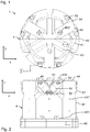
- the Figures 1 to 3 are respectively top, front and perspective views of a force measuring device 1 according to an exemplary embodiment of the invention.
- the device 1 comprises in particular a processing device 2 and a support 4 (intended to be requested or intended to receive a sample to be requested) comprising displacement sensors connected to the processing device 2.
- the Figures 4 and 5 are sectional views of the support 4.
- the support 4 comprises a base 40 and a fixed body 41 fixed to the base 40 by means of screws 401.
- Non-contact displacement sensors 51 are fixed to an external wall of the fixed body 41 by means of flanges 54 and of screws 53.
- the contactless sensors 51 are here of the capacitive type and measure the spacing between the sensor 51 and a respective metal wall of a support 44.
- the sensors 51 include connectors 52 connected to the processing device 2.
- the fixed body 41 has a vertical tubular part.
- the fixed body 41 has a central, vertical and through bore 415, formed in the tubular part.
- An intermediate movable body 42 is housed in the bore 415.
- the intermediate movable body 42 is connected to the fixed body 41 by means of at least one first elastically deformable link.
- the elastically deformable link is in particular intended to allow a displacement of the intermediate movable body 42 relative to the fixed body 41, in translation along the Z axis, and in rotation about the Z axis. The translations along the X and Y axes are globally blocked.
- the connecting element here comprises two connecting pieces 61 which are described in more detail below. Due to the use of two connecting pieces superimposed and spaced along the Z axis, rotations around the X and Y axes are generally blocked.
- a shoulder is formed in the bore 415.
- the fixed body 41 further comprises a clamping ring 414 screwed inside the bore 415.
- a spacer 411, an external ring 611 (of a connecting piece 61) , a spacer 422, another external ring 611 (from another connecting piece 61) and a spacer 413 are compressed in this order between the clamping ring 414 and the shoulder formed in the bore 415.
- the intermediate movable body 42 comprises a tubular part provided with a shoulder in its lower part.
- the intermediate movable body 42 further comprises a clamping ring 45 onto which the tubular part is screwed.
- a spacer 421, an internal ring 613 (of a connecting piece 61), a spacer 422, another internal ring 613 (of another connecting piece 61) and a spacer 423 are compressed in this order between the ring tightening 45 and the shoulder of the tubular part.
- Each internal ring 613 is connected to a concentric external ring 611, by means of several rods 612 detailed later.
- the connecting piece 61 here comprises three rods distributed angularly around the internal ring 613 and extending radially between the internal ring 613 and the external ring 611.
- An annular plate 436 is screwed onto the clamping ring 45 of the intermediate movable body 42.
- Connecting pieces 62 (in this case in the form of rods) are embedded at one end in the annular plate 436 and extend in the direction Z.
- the connecting pieces 62 are moreover embedded by another end in another annular plate 456.
- the annular plate 456 belongs to a movable support body 43.
- the movable support body 43 and thus connected to the intermediate movable body 42 via a second elastically deformable link.
- the elastically deformable link is in particular intended to allow a movement of the mobile body 43 relative to the intermediate mobile body 42, in translation along the axes X and Y. The translation along the axis Z and generally blocked by the rigidity of the connecting pieces 62 along this axis.
- This support body 43 is for example intended for fixing a sample or a sample holder on which forces must be applied.
- a sample holder plate 437 is fixed to the annular plate 456.
- a mirror support 44 is fixed to the plate 437 by means of screws 432.
- the displacement sensors 51 are in practice fixed vis-à-vis respective surfaces of the support 44, so that the variation in distance between a sensor 51 and its facing surface implies a variation in the capacity formed between the sensor 51 and this surface.
- the displacement measurement does not induce parasitic stresses during a relative displacement between the fixed body 41 and the mobile support body 43.
- the processing device 2 extrapolates the forces applied to the mobile body 43 along different axes: for example a force applied along the axes X, Y or Z, or a torque applied around the X, Y or Z axes.
- the matrix for transforming displacements into forces can be calibrated according to a predefined procedure.
- One can for example fix a stress frame on the movable body 43, to exert different forces and / or calibrated torque on this body 43.
- a man / machine interface controlled by the processing device 2 can for example solicit the user so that 'it positions calibrated masses at appropriate locations in the stressing frame, for example more or less eccentric from the Z axis.
- Other calibrated forces can be applied to the stressing frame along the X and Y axes, eccentrically or not.
- the matrix for transforming displacements into forces can then be generated from all of the corresponding displacement measurements, using a calibration method described below in a generic manner.
- the forces can be applied with amplitudes and predefined locations on the movable body 43, for example by fixing a support on the movable body 43, making it possible to apply weights at different locations with lever arms.
- a unit vector of the force direction measured by the index sensor i A unit vector of the force direction measured by the index sensor i.
- This matrix then makes it possible to express the 6 types of effort applied to a platform from 6 sensor measurements.
- the calibration of the system then consists in applying known forces and in carrying out measurements for the various sensors to extrapolate the matrix. This principle of calibration can easily be transposed to displacement measurements obtained for known forces.
- the matrix [A] can then be obtained from 6 measurements for known forces and expressed as follows:
- the cross-reaction values measured between the axes are less than 1% in effort and in moment.
- the linearity error of the measurements on all axes remained less than 1% for a range from 0.01N to 10 N.
- the figure 6 is a detailed sectional view of a variant connection between the fixed body 41 and the intermediate movable body 42.
- independent rods 63 are introduced through the orifices 617.
- Lower rods 63 have a compressed end between the spacer 417 and the spacer 422 and another compressed end between the spacer 412 and the spacer 413.
- Upper rods 63 have one compressed end between the spacer 422 and the spacer 421, and another compressed end between the spacer 422 and the spacer 411.
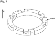
- the figure 7 is a perspective view of a base 40 for the fixed body of the support 4.
- the base 40 has an annular shape delimiting an orifice in its central part.
- the base 40 has an upper flat support surface and a lower flat support surface.
- the base comprises countersinks at the level of which through bores are provided, in order respectively to accommodate a screw head and to allow the body of this screw to pass. Such screws make it possible to fix the base 40 for example to a frame of a test installation.
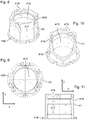
- the figures 8 to 11 are different views of the fixed body 41.
- the fixed body 41 has a flange 416 in its lower part.
- the underside of the flange 416 is flat and intended to be positioned against the base 40.
- the tubular part extends upwards from the base 416. This tubular part has a hexagonal external section and a circular internal section.
- Ports 417 are formed in the walls of the tubular part and put the bore 415 in communication with the outside.
- the orifices 417 can both facilitate the evacuation of the bore 415, or allow the attachment of rods 63 as illustrated in the variant of the figure 6 .
- Grooves 418 are formed in external faces of the tubular part. These grooves 418 are oriented at 45 ° relative to the vertical. The grooves 418 are intended to receive non-contact sensors 51.
- the sensors 51 positioned in the grooves 458 have non-collinear displacement measurement directions in the illustrated configuration. Threaded bores are provided on either side of each groove 418, so as to allow the fixing of the flanges 54 by means of screws 53.
- Notches 419 are provided at the upper end of the tubular part. These notches 419 are positioned at the intersection between two grooves 418. The notches 419 make it possible to position a support 44 for mirrors, common to two non-contact sensors 51. The sensors 51 can thus be distributed in pairs around the axis Z.
- a shoulder is provided in the upper part of the bore 415 in order to be able to hold the spacer 411.
- the lower part of the bore 415 is threaded, in order to allow the ring 414 to be screwed.
- the figure 12 is a perspective view of a flange 54 for fixing a contactless sensor 51 on the fixed body 41.
- the flange 54 has a central part in which a groove 541 is formed. Bores 542 are provided on either side of this groove 541. The bores 542 are intended for fixing the flange 54 on the fixed body 41 by screws, so as to position a contactless sensor 51 in the groove 541 and in keeping it pinched between the flange 54 and the fixed body 41.
- the figure 13 is a side view of a clamping ring 414 of the fixed body 41.
- the clamping ring 414 On its underside, the clamping ring 414 has lugs making it possible to drive it in rotation about a vertical axis.
- the clamping ring 414 has an orifice in its central part.
- the clamping ring 414 has a cylindrical section in its upper part and a cylindrical section in its intermediate part. The external face of the intermediate part has a thread making it possible to screw the clamping ring 414 into the fixed body 41.
- the figure 14 is a top view of a connecting piece 61 of an alternative embodiment of the invention.
- This connecting piece 61 comprises an external ring 611 and an internal ring 613.
- the external ring 611 is intended to be fixed to the fixed body 41.
- the internal ring 613 is intended to be fixed to the movable body 42.
- the external ring 611 and the inner ring 613 are connected by rods 612.
- the rods 612 are here three in number and are distributed around the axis Z.
- the rods 612 are here formed in one piece with the external ring 611 and the ring internal 613. This limits the number of components necessary to form the support 4, which makes it possible to limit mechanical dispersions and to limit the number of potential gas pockets for application in a vacuum.
- each of the rods 612 is here relatively high compared to its section.
- the following relation can for example be respected: L> 10 * ⁇ (S) with L the length of a rod 612 and S its cross section.
- each of the rods 612 turns out to be rigid in the face of contraction / compression stresses along its length.
- the movements of the movable body 42 relative to the fixed body 41 in the plane X, Y have an extremely reduced amplitude.
- Such a connecting piece 61 is advantageously removable to be separated from the fixed body 41 and the movable body 42.
- rods 612 provide the connection between the fixed body 41 and the intermediate movable body 42. These rods 612 have a square cross section of 1 mm side in stainless steel. Such rods 612 prove to be suitable, for example, for applying a force along the Z axis of 50N on the movable body 42, or for applying a torque around the Z axis of 100 ⁇ N on the movable body 42.
- the connecting pieces 61 and the connecting pieces 62 advantageously make it possible to obtain a displacement travel of the support body 43 relative to the fixed body 41 with an amplitude at least 50 times less than the distance between any two sensors 51. It is thus possible to characterize a relative displacement between the support body 43 and the fixed body 41 of small amplitude, for which the relationship between the forces applied and the displacements obtained has great linearity.
- the figure 15 is a perspective view of the intermediate movable body 42 on which various elements are fixed.
- the movable body 42 has a through bore 425 at its center.
- the movable body 42 has a cylindrical part 428 in its upper part, this cylindrical part surrounding the bore 425 and having a threaded external face.
- the through bore 425 provides access to reach the movable support body 43 from below.
- a measurement instrumentation, a camera or a heating resistor can be positioned near the moving body 43 and the sample that it can be brought to bear.
- the lower part of the movable body 42 is advantageously perforated, in order to facilitate vacuuming in the through bore 425.
- the movable body 42 has a shoulder 429 in its lower part in order to allow a spacer 423 to be maintained. Furthermore , the movable body 42 has lugs at its lower end, to allow it to rotate.
- the figure 16 is a perspective view of a spacer 422 for the intermediate movable body 42.
- the spacer 422 has a through bore in its central part.
- the spacer 422 is intended to come into line with the shoulder 429, to allow the internal ring to be maintained between this spacer 422 and the shoulder 429.
- the side wall of the shoulder 422 is advantageously perforated in order to facilitate vacuuming in the through bore 425.
- the Figures 17 and 18 illustrate a clamping ring 45 for the intermediate movable body 42.
- the clamping ring 45 comprises a cylindrical part 453.
- a through bore 454 is formed in the central part of the cylindrical part 453.
- Lugs 452 project radially towards the outside from the cylindrical part 453.
- Vertical threaded bores are provided in the lugs 452.
- the upper face of the lugs 452 is flat.
- the wall 455 of the bore 454 is threaded.
- the clamping ring 45 can also be screwed onto the cylindrical part 428.
- a shoulder is formed in the lower part of the clamping ring 45, so as to be able to maintain a ring 613 between this shoulder and the spacer 422.
- the figure 19 illustrates an annular plate 456 belonging to the intermediate movable body 42.
- a bore is formed in its center. This central bore is intended to be positioned around the cylindrical part 453 of the clamping ring 45.
- the annular plate 456 has flat upper and lower faces. The underside of the plate 456 is pressed against the lugs 452 of the clamping ring 45.
- Through bores 457 are formed in its annular part. The bores 457 are advantageously distributed angularly around the central bore.
- the bores 457 are intended to be crossed by a screw and are intended to be arranged opposite the bores 451 of the ring 45.
- Through bores 458 are also provided in the annular part.
- the bores 458 are advantageously distributed angularly around the central bore.
- the bores 458 are intended to receive one end of a rod 62.
- the figures 20 and 21 illustrate an annular plate 433 belonging to the support body 43.
- a bore 436 is formed in its center.
- the annular plate 433 has a flat upper face formed in its annular part.
- Through holes 435 are provided in the annular part.
- the bores 435 are advantageously distributed angularly around the bore 436.
- Threaded bores 434 are provided in the annular part and extend into studs projecting from a lower face of the plate.
- the figure 22 illustrates an annular plate 433 connected to an annular plate 456 by means of rods 62.
- the rods 62 are oriented vertically.
- the rods 62 have one end embedded in respective bores of the annular plate 433 and another end embedded in respective bores of the annular plate 456.
- the figures 23 and 24 illustrate a sample holder plate 437.
- the plate 437 has grooves 439 meeting at its center and oriented at 60 ° relative to each other. Some grooves have through bores 438.
- the plate 437 can be configured for fixing a sample or a sample holder.
- the plate 437 here has a flat lower face and studs on its upper face, forming flat surfaces.
- the figure 25 is a perspective view of an example of support 44 for mirror.
- the support 44 has a flat upper face and a fixing end, the lower face of which is flat.
- a bore 441 is formed through the fixing end. This lower face is intended to be received in a groove 439 of the plate 437.
- the bore 441 is intended for fixing by a screw 432 engaging in the threaded bore 434 of the annular plate 433. Such a screw 432 passes through a bore 438 of the plate 437.
- the plate 437 is thus kept pressed between the supports 44 and the annular plate 433.
- the support 44 has one end projecting from the plate 437. This end here has inclined and reflective surfaces 442.
- the surfaces 442 are here obtained by polishing a support 44 made of steel.
- the surfaces 442 are here inclined at 45 ° relative to the flat upper face of the support. Each surface 442 is therefore here parallel to the end of a respective capacitive sensor 51 and positioned opposite.
- Fixing the sensors with an inclination (relative to the degrees of freedom defined between the body 41, the body 42 and the body 43) makes it possible to improve the accuracy of the measurement by inducing a measurement redundancy for the same degree of freedom.
- the processing device 2 advantageously includes a network of in situ programmable doors (usually designated by the term FPGA) connected to the contactless sensor 51 is configured to extrapolate the forces applied to the body 43 as a function of the displacements measured by the sensors 51.
- a processing device 2 makes it possible, for example, to have a calculation of the forces almost in real time, which makes it possible for example to produce a servo-control with a value set point of effort.
- Such a processing device 2 also makes it possible to choose between average force values or instantaneous force values.
- Such a network of programmable doors can for example be implemented in the form of a controller sold under the reference 9224 associated with analog acquisition modules sold under the reference CompactRIO 9239 by the company National Instruments.
- Most of the support components will advantageously be made of stainless steel. Such a material proves to be particularly advantageous in the context of measurements carried out in a vacuum, due to the very small quantity of volatile compounds which it is able to emit.
- non-contact capacitive type sensors 51 are used. Such sensors prove in particular to be advantageous for short displacement strokes between the fixed body 41 and the mobile body 43. Measurements have been made by combining sensors sold under the reference MCC10 by the company Fogale with associated electronics sold under the reference MC900. The signals were acquired via NI-9239 reference 24-bit anti-folded delta sigma converters. Displacement signals were acquired at 50kHz, then digitally filtered using a Tchebitchev low-pass filter of order 2 set to 10Hz. The resolutions obtained are a few ⁇ N in force, and a few 1.10 -4 Nm over the moments. Other types of contactless sensors can also be used, depending on the intended applications.
- the mirrors are then for example placed opposite such sensors.
- Such sensors are for example particularly advantageous in a high temperature environment and when such sensors are distant from their processing circuit.
- optical sensors 51 are for example based on the receptivity of a light signal to an optical fiber.
- the body 41 and the body 42 are connected by means of rods 612.
- These membranes can be perforated so as to create different sensitivities depending on the use of the sensor.
Landscapes
- Physics & Mathematics (AREA)
- General Physics & Mathematics (AREA)
- Force Measurement Appropriate To Specific Purposes (AREA)
Description
L'invention concerne les dispositifs de mesure d'efforts, en particulier les dispositifs de mesure d'efforts pour laboratoire impliquant une grande précision des mesures.The invention relates to force measurement devices, in particular laboratory force measurement devices involving high measurement accuracy.
Les dispositifs de mesure d'efforts sont par exemple utilisés dans le domaine de la tribologie afin de déterminer un coefficient de frottement entre deux solides. Dans un certain nombre d'applications, les niveaux d'efforts mesurés sont relativement réduits et toute imprécision ou perturbation de mesure peut induire des erreurs dépassant l'ordre de grandeur des efforts à mesurer. Certaines mesures réalisées sous vide ou dans des atmosphères contrôlées exigent notamment des précisions de mesure d'efforts que les dispositifs de mesure connus sont incapables de fournir.The force measurement devices are for example used in the field of tribology in order to determine a coefficient of friction between two solids. In a certain number of applications, the levels of force measured are relatively reduced and any inaccuracy or disturbance of measurement can induce errors exceeding the order of magnitude of the forces to be measured. Certain measurements carried out under vacuum or in controlled atmospheres in particular require precision of measurement of forces which the known measuring devices are unable to provide.
Pour une application en tribologie, on doit mesurer à la fois un effort tangentiel et un effort normal sur un échantillon. Toute imprécision d'alignement des axes de mesure altère fortement la précision des mesures suivant ces axes, et donc le coefficient de frottement calculé par ce biais. Par ailleurs, les dispositifs de mesure d'efforts connus permettent difficilement de dissocier le niveau de précision ou le niveau d'efforts selon différents axes de mesure.For a tribology application, we must measure both a tangential force and a normal force on a sample. Any inaccuracy in alignment of the measurement axes greatly alters the accuracy of the measurements along these axes, and therefore the coefficient of friction calculated by this bias. Furthermore, known force measurement devices make it difficult to dissociate the level of precision or the level of force according to different measurement axes.
Le document
Le document
Le document
Le document
Le document
Un tel dispositif présent un certain nombre d'inconvénients. La précision sur les axes mesurés est insuffisante pour discriminer une force tangentielle et une force normale par exemple par ailleurs, la linéarité de la mesure d'efforts avec un tel dispositif est insuffisante et n'est donc utilisable que pour une gamme réduite d'efforts. Par ailleurs, la précision de mesure d'un tel dispositif est insuffisante, en particulier dans une application de mesure de coefficients de frottement très réduits.Such a device has a number of drawbacks. The precision on the measured axes is insufficient to discriminate between a tangential force and a normal force for example, moreover, the linearity of the measurement of forces with such a device is insufficient and can therefore only be used for a reduced range of forces. . Furthermore, the measurement accuracy of such a device is insufficient, in particular in an application for measuring very low coefficients of friction.
Le document décrit un dispositif de mesure d'efforts, comprenant une platine d'application d'effort, relié à un support par l'intermédiaire de 4 bras disposés en croix. Ces 4 bras comportent 4 transducteurs électro-magnétiques respectifs. Ces transducteurs électro-magnétiques mesurent chacun un déplacement vertical du dispositif de mesure d'efforts. Les différents efforts sont déterminés de façon simplifiée à partir de ces différents déplacements verticaux.The document describes a force measurement device, comprising a force application plate, connected to a support by means of 4 arms arranged in a cross. These 4 arms include 4 respective electromagnetic transducers. These electromagnetic transducers each measure a vertical displacement of the force measurement device. The different forces are determined in a simplified way from these different vertical displacements.
Un tel dispositif présente des inconvénients. La précision de mesure est relativement limitée. Par ailleurs, une erreur impacte l'ensemble des mesures de déplacement.Such a device has drawbacks. The measurement accuracy is relatively limited. In addition, an error affects all of the displacement measurements.
L'invention vise à résoudre un ou plusieurs de ces inconvénients. L'invention porte ainsi sur un dispositif de mesure d'efforts, tel que défini dans la revendication 1. L'invention porte également sur les variantes des revendications dépendantes. L'homme du métier comprendra que chacune des caractéristiques de ces revendications dépendantes peut être combinée indépendamment aux caractéristiques ci-dessus, sans pour autant constituer une généralisation intermédiaire.The invention aims to solve one or more of these drawbacks. The invention thus relates to a device for measuring forces, as defined in
D'autres caractéristiques et avantages de l'invention ressortiront clairement de la description qui en est faite ci-après, à titre indicatif et nullement limitatif, en référence aux dessins annexés, dans lesquels :
- les
figures 1 à 3 sont respectivement des vues de dessus, de face et en perspective d'un dispositif de mesure d'efforts selon un exemple de mode de réalisation de l'invention ; - les
figures 4 et 5 sont des vues en coupe du dispositif de mesure d'efforts selon lafigure 1 ; - la
figure 6 est une vue en coupe de détail d'une variante du dispositif de mesure d'efforts de lafigure 1 ; - la
figure 7 est une vue en perspective d'une embase du dispositif de mesure d'efforts de lafigure 1 ; - les
figures 8 et 9 sont respectivement des vues en perspectives et de dessus d'un corps fixe du dispositif de mesure d'efforts de lafigure 1 ; - les
figures 10 et 11 sont des vues en coupe du corps fixe du dispositif de mesure d'efforts de lafigure 1 ; - la
figure 12 est une vue en perspective d'une bride pour un capteur de déplacement ; - la
figure 13 est une vue de côté d'une bague de serrage pour le corps fixe; - la
figure 14 est une vue de dessus d'un élément de liaison avec le corps fixe ; - la
figure 15 est une vue en perspective d'un corps mobile intermédiaire ; - la
figure 16 est une vue en perspective d'une entretoise pour le corps mobile intermédiaire ; - les
figures 17 et 18 illustrent une bague de serrage pour le corps mobile intermédiaire ; - la
figure 19 est une vue en perspective d'une plaque annulaire fixée sur la bague de serrage de lafigure 17 ; - les
figures 20 et 21 illustrent une plaque annulaire d'un corps mobile porte échantillon ; - la
figure 22 est une vue en perspective des plaques annulaires solidarisées par des tiges flexibles ; - les
figures 23 et 24 illustrent une platine porte échantillon sur lequel la plaque annulaire de lafigure 20 est fixée - la
figure 25 est une vue en perspective d'un support pour miroir ;
- the
Figures 1 to 3 are respectively top, front and perspective views of a force measurement device according to an exemplary embodiment of the invention; - the
Figures 4 and 5 are sectional views of the force measurement device according to thefigure 1 ; - the
figure 6 is a detailed sectional view of a variant of the force measurement device of thefigure 1 ; - the
figure 7 is a perspective view of a base of the force measurement device of thefigure 1 ; - the
Figures 8 and 9 are respectively perspective and top views of a fixed body of the force measurement device of thefigure 1 ; - the
figures 10 and 11 are sectional views of the fixed body of the force measurement device of thefigure 1 ; - the
figure 12 is a perspective view of a flange for a displacement sensor; - the
figure 13 is a side view of a clamping ring for the fixed body; - the
figure 14 is a top view of a connecting element with the fixed body; - the
figure 15 is a perspective view of an intermediate movable body; - the
figure 16 is a perspective view of a spacer for the intermediate movable body; - the
Figures 17 and 18 illustrate a clamping ring for the intermediate movable body; - the
figure 19 is a perspective view of an annular plate fixed on the clamping ring of thefigure 17 ; - the
figures 20 and 21 illustrate an annular plate of a mobile sample holder body; - the
figure 22 is a perspective view of the annular plates secured by flexible rods; - the
figures 23 and 24 illustrate a sample plate on which the annular plate of thefigure 20 is fixed - the
figure 25 is a perspective view of a mirror support;
Les
Le support 4 comporte une embase 40 et un corps fixe 41 fixés sur l'embase 40 par l'intermédiaire de vis 401. Des capteurs de déplacement sans contact 51 sont fixés sur une paroi externe du corps fixe 41 par l'intermédiaire de brides 54 et de vis 53. Les capteurs sans contact 51 sont ici de type capacitif et mesurent l'espacement entre le capteur 51 et une paroi métallique respective d'un support 44. Les capteurs 51 comportent des connecteurs 52 raccordés au dispositif de traitement 2.The
Le corps fixe 41 comporte une partie tubulaire verticale. Le corps fixe 41 comporte un alésage central, vertical et traversant 415, ménagé dans la partie tubulaire. Un corps mobile intermédiaire 42 est logé dans l'alésage 415. Le corps mobile intermédiaire 42 est relié au corps fixe 41 par l'intermédiaire d'au moins une première liaison déformable élastiquement. La liaison déformable élastiquement est notamment destinée à permettre un déplacement du corps mobile intermédiaire 42 par rapport au corps fixe 41, en translation suivant l'axe Z, et en rotation autour de l'axe Z. Les translations selon les axes X et Y sont globalement bloquées.The fixed
L'élément de liaison comporte ici deux pièces de liaison 61 davantage détaillées par la suite. Du fait de l'utilisation de deux pièces de liaison superposées et espacées selon l'axe Z, des rotations autour des axes X et Y sont globalement bloquées.The connecting element here comprises two connecting
Un épaulement est ménagé dans l'alésage 415. Le corps fixe 41 comporte en outre une bague de serrage 414 vissée à l'intérieur de l'alésage 415. Une entretoise 411, un anneau externe 611 (d'une pièce de liaison 61), une entretoise 422, un autre anneau externe 611 (d'une autre pièce de liaison 61) et une entretoise 413 sont comprimés dans cet ordre entre la bague de serrage 414 et l'épaulement ménagé dans l'alésage 415.A shoulder is formed in the
Le corps mobile intermédiaire 42 comporte une partie tubulaire munie d'un épaulement dans sa partie inférieure. Le corps mobile intermédiaire 42 comporte en outre une bague de serrage 45 sur laquelle est vissée la partie tubulaire. Une entretoise 421, un anneau interne 613 (d'une pièce de liaison 61), une entretoise 422, un autre anneau interne 613 (d'une autre pièce de liaison 61) et une entretoise 423 sont comprimés dans cet ordre entre la bague de serrage 45 et l'épaulement de la partie tubulaire. Chaque anneau interne 613 est relié à un anneau externe concentrique 611, par l'intermédiaire de plusieurs tiges 612 détaillées ultérieurement. La pièce de liaison 61 comporte ici trois tiges réparties angulairement autour de l'anneau interne 613 et s'étendant radialement entre l'anneau interne 613 et l'anneau externe 611.The intermediate
Une plaque annulaire 436 est vissée sur la bague de serrage 45 du corps mobile intermédiaire 42. Des pièces de liaison 62 (en l'occurrence sous forme de tiges) sont encastrées par une extrémité dans la plaque annulaire 436 et s'étendent selon la direction Z. Les pièces de liaison 62 sont par ailleurs encastrées par une autre extrémité dans une autre plaque annulaire 456.An
La plaque annulaire 456 appartient à un corps de support mobile 43. Le corps de support mobile 43 et ainsi relié au corps mobile intermédiaire 42 par l'intermédiaire d'une deuxième liaison déformable élastiquement. La liaison déformable élastiquement est notamment destinée à permettre un déplacement du corps mobile 43 par rapport au corps mobile intermédiaire 42, en translation suivant les axes X et Y. La translation selon l'axe Z et globalement bloquée par la rigidité des pièces de liaison 62 suivant cet axe.The
Ce corps de support 43 est par exemple destiné à la fixation d'un échantillon ou d'un porte échantillon sur lequel des efforts doivent être appliqués. Une platine porte échantillon 437 est fixée sur la plaque annulaire 456. Un support pour miroir 44 est fixé sur la platine 437 par l'intermédiaire de vis 432. Les capteurs de déplacement 51 sont en pratique fixés en vis-à-vis de surfaces respectives du support 44, de sorte que la variation de distance entre un capteur 51 et sa surface en vis-à-vis implique une variation de la capacité formée entre le capteur 51 et cette surface.This
Du fait de l'utilisation de capteurs de déplacement sans contact 51, la mesure de déplacement n'induit pas de contraintes parasites durant un déplacement relatif entre le corps fixe 41 et le corps mobile de support 43.Due to the use of
En fonction des différents déplacements mesurés par les capteurs 51 entre le corps mobile 43 et le corps fixe 41, le dispositif de traitement 2 extrapole les efforts appliqués sur le corps mobile 43 selon différents axes : par exemple une force appliquée selon les axes X, Y ou Z, ou un couple appliqué autour des axes X, Y ou Z.Depending on the different displacements measured by the
La matrice de transformation des déplacements en efforts peut-être étalonnée selon une procédure prédéfinie. On peut par exemple fixer un cadre de sollicitations sur le corps mobile 43, pour exercer différents efforts et/ou couple calibré sur ce corps 43. Une interface homme/machine pilotée par le dispositif de traitement 2 peut par exemple solliciter l'utilisateur pour qu'il positionne des masses calibrées en des emplacements appropriés du cadre de sollicitation, par exemple plus ou moins excentrés de l'axe Z. D'autres efforts calibrés peuvent être appliqués sur le cadre de sollicitation suivant les axes X et Y, de façon excentrée ou non. La matrice de transformation des déplacements en efforts peut alors être générée à partir de l'ensemble des mesures de déplacements correspondantes, en utilisant une méthode de calibration décrite ci-dessous de façon générique. Les efforts peuvent être appliqués avec des amplitudes et des localisations prédéfinies sur le corps mobile 43, par exemple en fixant un support sur le corps mobile 43, permettant d'appliquer des poids en différents emplacements avec des bras de levier.The matrix for transforming displacements into forces can be calibrated according to a predefined procedure. One can for example fix a stress frame on the
Pour extrapoler une matrice de transformation, on peut considérer qu'un plateau de mesure est relié à une embase fixe par l'intermédiaire de six capteurs d'efforts indépendants correspondant à 6 liaisons respectives.To extrapolate a transformation matrix, we can consider that a measurement plate is connected to a fixed base via six independent force sensors corresponding to 6 respective links.
On prendra par la suite les notations suivantes :
- O un point d'origine ;
- Ai une extrémité inférieure de la ième liaison entre le plateau de mesure et l'embase fixe ;
- Bi une extrémité supérieure de la ième liaison entre le plateau de mesure et l'embase fixe ;
- Fi : la force mesurée par le capteur d'indice i

- O a point of origin;
- Ai a lower end of the ith connection between the measurement plate and the fixed base;
- Bi an upper end of the ith connection between the measurement plate and the fixed base;
- Fi: the force measured by the index sensor i
Un vecteur unitaire de la direction d'effort mesurée par le capteur d'indice i.A unit vector of the force direction measured by the index sensor i.
Le vecteur d'effort mesuré par le catpeur i peut aussi être exprimé par 
On définit les coordonnées des points Ai et Bi par : 
On exprime les moments L, M et N selon les axes x, y et z à l'origine du système de coordonnées de la façon suivante : 
En sommant les forces et les moments exprimés à l'origine du système de coordonnées pour chaque axe de projection, on obtient : 
Ce qui peut s'exprimer de la façon suivante sous forme d'équation matricielle : 
Cette matrice permettant alors d'exprimer les 6 types d'effort appliqués à un plateau à partir de 6 mesures des capteurs.This matrix then makes it possible to express the 6 types of effort applied to a platform from 6 sensor measurements.
La calibration du système consiste alors à appliquer des efforts connus et à réaliser des mesures pour les différents capteurs pour extrapoler la matrice. Ce principe de calibration peut aisément être transposé à des mesures de déplacements obtenus pour des efforts connus.The calibration of the system then consists in applying known forces and in carrying out measurements for the various sensors to extrapolate the matrix. This principle of calibration can easily be transposed to displacement measurements obtained for known forces.
Des éléments mij d'une telle matrice peuvent notamment être déduits de la résolution de
![]()
![]()
Avec

La matrice [A] peut alors être obtenue à partir de 6 mesures pour des efforts connus et exprimé de la façon suivante :
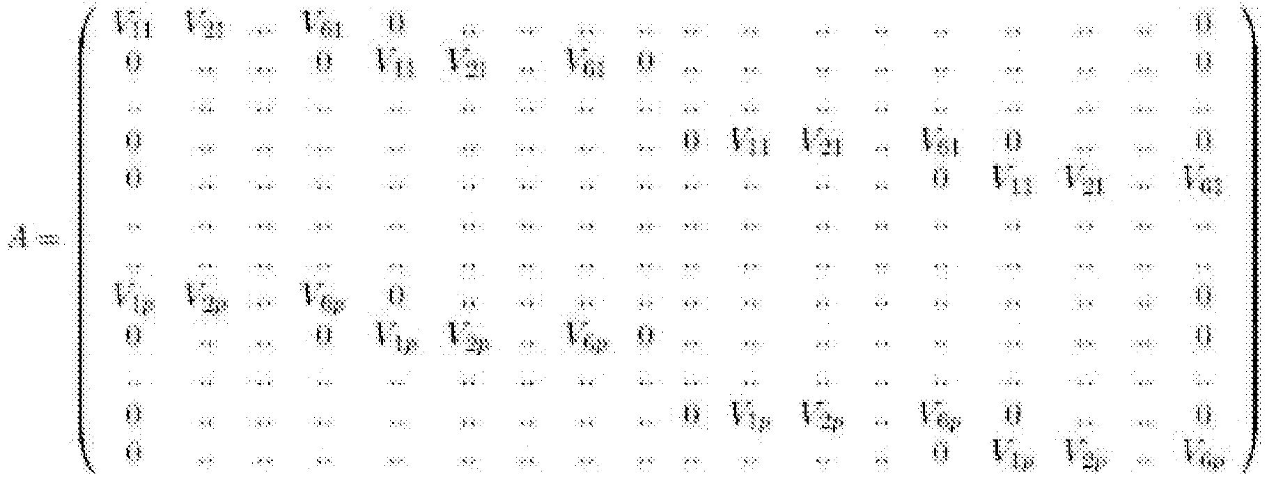
Avec Vip la mesure pour la liaison d'indice i lorsque une force p est appliquée.With Vip the measurement for the bond of index i when a force p is applied.
La matrice Y est alors exprimée à partir du torseur appliqué à la structure : 
On peut bien entendu appliquer plus de 6 efforts à la structure, ce qui conduit à la résolution d'un système surdéterminé, dont la solution peut être approximée par une méthode des moindres carrés.It is of course possible to apply more than 6 forces to the structure, which leads to the resolution of an overdetermined system, the solution of which can be approximated by a method of least squares.
Des simulations ont permis de déterminer une résolution de 10µN et 0,1N.mm à 50KHz respectivement pour les efforts suivant l'axe Z et les moments autour de l'axe Z. L'axe Z ayant été privilégié, la résolution des efforts selon les axes X ou Y est de 100µN et la résolution des moments autour des axes X ou Y est de 1 N.mm à 50kHz.Simulations made it possible to determine a resolution of 10 μN and 0.1 N. mm at 50 kHz respectively for the forces along the Z axis and the moments around the Z axis. The Z axis having been favored, the resolution of the forces according to the X or Y axes is 100µN and the resolution of the moments around the X or Y axes is 1 N.mm at 50kHz.
Pour une application particulière à des mesures de coefficients de frottement, on peut obtenir une incertitude de mesure de coefficient de l'ordre de 10-4 ou moins.For a particular application to measurements of friction coefficients, one can obtain a coefficient measurement uncertainty of the order of 10 -4 or less.
Les valeurs de réactions croisées mesurées entre les axes sont inférieures à 1% en efforts et en moment.The cross-reaction values measured between the axes are less than 1% in effort and in moment.
Le défaut de linéarité des mesures sur tous les axes est resté inférieur à 1% pour une gamme allant de 0,01N à 10 N.The linearity error of the measurements on all axes remained less than 1% for a range from 0.01N to 10 N.
La
La
Les
Des orifices 417 sont ménagés dans les parois de la partie tubulaire et mettent en communication l'alésage 415 avec l'extérieur. Les orifices 417 peuvent à la fois faciliter la mise sous vide de l'alésage 415, ou permettre la fixation de tiges 63 telles qu'illustrées dans la variante de la
Des rainures 418 sont ménagées dans des faces externes de la partie tubulaire. Ces rainures 418 sont orientées à 45° par rapport à la verticale. Les rainures 418 sont destinées à recevoir des capteurs sans contact 51. Les capteurs 51 positionnés dans les rainures 458 présentent des directions de mesure de déplacement non colinéaires dans la configuration illustrée. Des alésages filetés sont ménagés de part et d'autre de chaque rainure 418, de façon à permettre la fixation des brides 54 par l'intermédiaire de vis 53. Des encoches 419 sont ménagées au niveau de l'extrémité supérieure de la partie tubulaire. Ces encoches 419 sont positionnées à l'intersection entre deux rainures 418. Les encoches 419 permettent de positionner un support 44 pour miroirs, commun à deux capteurs sans contact 51. Les capteurs 51 peuvent ainsi être répartis par paires autour de l'axe Z.
Un épaulement est ménagé dans la partie supérieure de l'alésage 415 afin de pouvoir maintenir l'entretoise 411. La partie inférieure de l'alésage 415 est filetée, afin de permettre le vissage de la bague 414.A shoulder is provided in the upper part of the
La
La
La
La longueur de chacune des tiges 612 est ici relativement élevée par rapport à sa section. La relation suivante peut par exemple être respectée : L > 10 * √(S) avec L la longueur d'une tige 612 et S sa section transversale. Ainsi, un effort exercé selon la direction Z sur l'anneau interne 613 permet de faire fléchir une poutre 612, ce qui permet d'induire une translation du corps mobile 42 par rapport au corps fixe 41. Par ailleurs, un couple exercé sur l'anneau interne 613 autour de la direction Z permet d'induire un déplacement en rotation du corps mobile 42 par rapport au corps fixe 41. Le corps mobile 42 peut également être guidé en rotation par rapport audit corps 41 par d'autres moyens que par les tiges 612.The length of each of the
A contrario, chacune des tiges 612 s'avère rigide face à des sollicitations en contraction/compression selon sa longueur. Ainsi, les déplacements du corps mobile 42 par rapport au corps fixe 41 dans le plan X, Y présentent une amplitude extrêmement réduite.Conversely, each of the
Une telle pièce de liaison 61 est avantageusement démontable pour être séparée du corps fixe 41 et du corps mobile 42. Ainsi, par remplacement des pièces de liaison 61 par d'autres pièces de liaison ayant des tiges de sections différentes, on peut adapter différentes rigidités de la liaison entre le corps fixe 41 et le corps mobile 42 en conservant les autres pièces du support 4. On peut ainsi adapter l'amplitude des déplacements entre le corps fixe 41 et le corps mobiles 42 aux efforts à appliquer, afin de rester dans une gamme de déformation élastique de la pièce de liaison 61.Such a connecting
Dans l'exemple illustré, six tiges 612 assurent la liaison entre le corps fixe 41 et le corps mobiles intermédiaires 42. Ces tiges 612 présentent une section transversale carrée de 1 mm de côté en acier inoxydable. De telles tiges 612 s'avèrent par exemple appropriées pour appliquer une force selon l'axe Z de 50N sur le corps mobile 42, ou pour appliquer un couple autour de l'axe Z de 100 µN sur le corps mobile 42.In the example illustrated, six
De façon générale, les pièces de liaison 61 et les pièces de liaison 62 permettent avantageusement d'obtenir une course de déplacement du corps de support 43 par rapport au corps fixe 41 d'une amplitude au moins 50 fois inférieure à la distance entre deux quelconques des capteurs 51. On peut ainsi caractériser un déplacement relatif entre le corps de support 43 et le corps fixe 41 de faible amplitude, pour lequel la relation entre les efforts appliqués et les déplacements obtenus présente une grande linéarité.In general, the connecting
L'indépendance entre les pièces de liaison 61 et 62 permet aisément de dissocier la résolution de mesure suivant différents axes d'efforts, en fonction des besoins.The independence between the connecting
La
L'alésage traversant 425 fournit un accès permettant d'atteindre le corps mobile de support 43 par le dessous. Ainsi, une instrumentation de mesure, une caméra ou une résistance de chauffage peuvent être positionnées à proximité du corps mobile 43 et de l'échantillon qu'il peut être amené à supporter.The through
La partie inférieure du corps mobile 42 est avantageusement ajourée, afin de faciliter la mise sous vide dans l'alésage traversant 425. Le corps mobile 42 comporte un épaulement 429 dans sa partie inférieure afin de permettre un maintien d'une entretoise 423. Par ailleurs, le corps mobile 42 présente des ergots au niveau de son extrémité inférieure, afin de permettre son entraînement en rotation.The lower part of the
La
Les
La
Les
La
Les
La
Le support 44 comporte une extrémité placée en saillie par rapport à la platine 437. Cette extrémité présente ici des surfaces inclinées et réfléchissantes 442. Les surfaces 442 sont ici obtenues par polissage d'un support 44 en acier. Les surfaces 442 sont ici inclinées à 45° par rapport à la face supérieure plane du support. Chaque surface 442 est donc ici parallèle à l'extrémité d'un capteur capacitif 51 respectif et positionné en vis-à-vis.The
La fixation des capteurs avec une inclinaison (par rapport aux degrés de liberté définis entre le corps 41, le corps 42 et le corps 43) permet d'améliorer la précision de la mesure en induisant une redondance de mesure pour un même degré de liberté.Fixing the sensors with an inclination (relative to the degrees of freedom defined between the
Le dispositif de traitement 2 inclut avantageusement un réseau de portes programmables in situ (usuellement désigné par le terme FPGA) connecté au capteur sans contact 51 est configuré pour extrapoler les efforts appliqués sur le corps 43 en fonction des déplacements mesurés par les capteurs 51. Un tel dispositif de traitement 2 permet par exemple de disposer d'un calcul des efforts quasiment en temps réel, ce qui permet par exemple de réaliser un asservissement avec une consigne de valeur d'effort. Un tel dispositif de traitement 2 permet également de choisir entre des valeurs d'effort moyennes ou des valeurs d'effort instantanées. Un tel réseau de portes programmables peut par exemple être mis en œuvre sous la forme d'un contrôleur commercialisé sous la référence 9224 associé à des modules d'acquisition analogique commercialisés sous la référence CompactRIO 9239 par la société National Instruments.The
La plupart des composants du support seront avantageusement réalisés en acier inoxydable. Un tel matériau s'avère particulièrement avantageux dans le cadre de mesures effectuées dans le vide, du fait de la très faible quantité de composés volatils qu'il est à même d'émettre.Most of the support components will advantageously be made of stainless steel. Such a material proves to be particularly advantageous in the context of measurements carried out in a vacuum, due to the very small quantity of volatile compounds which it is able to emit.
Dans l'exemple illustré, on utilise des capteurs 51 sans contact de type capacitif. De tels capteurs s'avèrent en particulier avantageux pour de faibles courses de déplacement entre le corps fixe 41 et le corps mobiles 43. Des mesures ont été réalisées en associant des capteurs commercialisés sous la référence MCC10 par la société Fogale avec des électroniques associées commercialisées sous la référence MC900. Les signaux ont été acquis via des convertisseurs delta sigma 24 bits anti repliés de référence NI-9239. Les signaux de déplacements ont été acquis à 50kHz, puis filtrés numériquement au moyen d'un filtre passe bas de Tchebitchev d'ordre 2 réglés sur 10Hz. Les résolutions obtenues sont de quelques µN en forces, et de quelques 1.10-4 N.m sur les moments. D'autres types de capteurs sans contact peuvent également être utilisés, en fonction des applications visées.In the example illustrated, non-contact
On peut par exemple également envisager de remplacer les capteurs capacitifs 51 par des capteurs interférométriques de déplacement, tels que le capteur commercialisé sous la référence ECS3040 par la société AttoCube. Les miroirs sont alors par exemple placés en vis-à-vis de tels capteurs. De tels capteurs s'avèrent par exemple particulièrement avantageux dans un environnement à haute température et lorsque de tels capteurs sont distants de leur circuit de traitement.One can for example also consider replacing the
On peut également envisager de remplacer les capteurs capacitifs 51 par des capteurs optiques de déplacement. De tels capteurs optiques sont par exemple basés sur la réceptivité d'un signal lumineux vers une fibre optique.It is also conceivable to replace the
On peut encore envisager de remplacer les capteurs capacitifs 51 par des capteurs de déplacement du type à courant de Foucault.It is also conceivable to replace the
Dans l'exemple illustré, le corps 41 et le corps 42 sont reliés par l'intermédiaire de tiges 612. On peut cependant envisager d'autres types de liaison, par exemple une liaison par une (ou plus) membrane annulaire flexibles et s'étendant au repos dans un plan comprenant les axes X et Y.In the example illustrated, the
Ces membranes peuvent être ajourées de manière à créer des sensibilités différentes en fonction de l'utilisation du capteur.These membranes can be perforated so as to create different sensitivities depending on the use of the sensor.
Pour éviter la formation de poches de gaz néfastes à une application dans le vide, tous les alésages des composants du support 4 sont avantageusement débouchants.To avoid the formation of pockets of gases harmful to an application in a vacuum, all the bores of the components of the
Claims (11)
- Device for measuring forces, comprising:- a first body (41) that is intended to be immobilized;- a second body (42) that is guided in translation in at least a first direction with respect to the first body via at least one first elastically deformable connection (61);- a third body (43) that is intended to be subjected to a force and guided in at least three degrees of freedom with respect to the second body via at least one second elastically deformable connection in a second direction perpendicular to the first, said second connection being rigid (62) in said first direction;- at least first to fourth contactless sensors (51) for sensing the movement of the third body with respect to the first body, said first to fourth sensors measuring said movement in four respective directions;- a processing circuit (2) that calculates the forces applied to said third body depending on the movements measured by said first to fourth sensors; characterized in that:- said first to fourth contactless sensors for sensing the movement of the third body with respect to the first body measure said movement in four respective non-collinear directions.
- Device for measuring forces according to Claim 1, wherein said second body (42) is also guided in rotation about said first direction with respect to said first body (41) via said first connection.
- Device for measuring forces according to Claim 2, wherein said first connection comprises at least three rods (612) that are perpendicular to said first direction and distributed angularly about this first direction.
- Device for measuring forces according to Claim 3, wherein said first connection comprises two concentric rings (611, 613), said three rods (612) being formed integrally with said two concentric rings, the first concentric ring (611) being fixed to the first body, the second concentric ring (613) being fixed to the second body.
- Device for measuring forces according to Claim 3 or 4, wherein each of said rods (612) is rigid in a respective direction perpendicular to said first direction.
- Device for measuring forces according to any one of the preceding claims, wherein said second connection (62) comprises at least three rods that are parallel to said first direction and distributed angularly about said first direction.
- Device for measuring forces according to any one of the preceding claims, wherein said contactless sensors (51) are capacitive sensors, and wherein first to fourth mirrors (442) are fixed to said body (43) facing the first to fourth sensors, respectively.
- Device for measuring forces according to Claim 7, comprising fifth and sixth contactless sensors for sensing the movement of the third body with respect to the first body in two respective directions that are non-collinear with the movement measuring directions of said first to fourth contactless sensors.
- Device for measuring forces according to Claim 8, wherein said sensors are distributed in pairs about said first direction.
- Device for measuring forces according to any one of the preceding claims, wherein the movement path of the third body with respect to the first body in any direction is at least 50 times smaller than the distance between any two of said sensors.
- Device for measuring forces according to any one of the preceding claims, wherein said sensors are connected to at least one in situ programmable gate array that is included in said processing circuit and extrapolates forces applied to said third body depending on the movements measured by said first to fourth sensors.
Priority Applications (1)
| Application Number | Priority Date | Filing Date | Title |
|---|---|---|---|
| PL16733654T PL3308120T3 (en) | 2015-06-12 | 2016-06-02 | High-precision device for measuring forces |
Applications Claiming Priority (2)
| Application Number | Priority Date | Filing Date | Title |
|---|---|---|---|
| FR1555388A FR3037396B1 (en) | 2015-06-12 | 2015-06-12 | HIGH PRECISION EFFORTS MEASURING DEVICE |
| PCT/FR2016/051316 WO2016198766A1 (en) | 2015-06-12 | 2016-06-02 | High-precision device for measuring forces |
Publications (2)
| Publication Number | Publication Date |
|---|---|
| EP3308120A1 EP3308120A1 (en) | 2018-04-18 |
| EP3308120B1 true EP3308120B1 (en) | 2020-05-06 |
Family
ID=53801062
Family Applications (1)
| Application Number | Title | Priority Date | Filing Date |
|---|---|---|---|
| EP16733654.4A Active EP3308120B1 (en) | 2015-06-12 | 2016-06-02 | High-precision device for measuring forces |
Country Status (4)
| Country | Link |
|---|---|
| EP (1) | EP3308120B1 (en) |
| FR (1) | FR3037396B1 (en) |
| PL (1) | PL3308120T3 (en) |
| WO (1) | WO2016198766A1 (en) |
Families Citing this family (1)
| Publication number | Priority date | Publication date | Assignee | Title |
|---|---|---|---|---|
| FR3097049B1 (en) * | 2019-06-07 | 2021-05-07 | Safran Aircraft Engines | Method and system for determining the coefficient of friction in a bolted connection |
Family Cites Families (4)
| Publication number | Priority date | Publication date | Assignee | Title |
|---|---|---|---|---|
| US6363798B1 (en) * | 2000-07-24 | 2002-04-02 | Norm Gitis | Method and device for measuring forces |
| US8276466B2 (en) * | 2010-03-31 | 2012-10-02 | Kulite Semiconductor Products, Inc. | Two or three-axis shear load cell |
| JP5836633B2 (en) * | 2011-05-10 | 2015-12-24 | キヤノン株式会社 | Force sensor and assembly robot |
| EP2549253B1 (en) | 2011-07-19 | 2017-08-09 | Magna Steyr Fahrzeugtechnik AG & Co KG | Measuring body, force sensor and measuring assembly for measuring forces |
-
2015
- 2015-06-12 FR FR1555388A patent/FR3037396B1/en active Active
-
2016
- 2016-06-02 PL PL16733654T patent/PL3308120T3/en unknown
- 2016-06-02 WO PCT/FR2016/051316 patent/WO2016198766A1/en active Application Filing
- 2016-06-02 EP EP16733654.4A patent/EP3308120B1/en active Active
Non-Patent Citations (1)
| Title |
|---|
| None * |
Also Published As
| Publication number | Publication date |
|---|---|
| PL3308120T3 (en) | 2021-01-11 |
| FR3037396B1 (en) | 2017-06-23 |
| WO2016198766A1 (en) | 2016-12-15 |
| EP3308120A1 (en) | 2018-04-18 |
| FR3037396A1 (en) | 2016-12-16 |
Similar Documents
| Publication | Publication Date | Title |
|---|---|---|
| EP0325521B1 (en) | Automatic balancing device for a centrifuge in operation | |
| EP2251634B1 (en) | Dimension measuring instrument consisting in a vertical measurement column | |
| FR2596861A1 (en) | ROTATION TORQUE AND FORCE DETECTOR, EQUIPPED WITH EXTENSOMETRIC GAUGES | |
| JP6212148B2 (en) | Measuring probe | |
| EP2347217B1 (en) | Method for calibrating a device for optical curvature monitoring | |
| CA2912163C (en) | Oligocyclic fatigue or oligocyclic and polycyclic fatigue test rig | |
| EP3308120B1 (en) | High-precision device for measuring forces | |
| WO2017099602A1 (en) | Pressure sensor and sensor system comprising one or more pressure sensors. | |
| EP3071976B1 (en) | Sensor with moving sensitive element having mixed vibrating and pendular operation, and methods for controlling such a sensor | |
| CA2885523A1 (en) | Pressure sensor made from nanogauges coupled to a resonator | |
| WO2014092523A1 (en) | Device for controlling the alignment of transmission shafts | |
| EP0395649A1 (en) | Device for checking linear dimensions of parts | |
| FR2459462A1 (en) | Diaphragm dynamometer for measurement of applied force - has axial guide assembly with capacitive sensor on load shaft | |
| LU84283A1 (en) | DIFFERENTIAL PRESSURE SENSOR | |
| FR2930936A1 (en) | SYSTEM FOR CONTROLLING A DOUBLE-MEDIUM DRIVING GANTRY | |
| CA2983187A1 (en) | Deformation measuring torque meter | |
| FR3093175A1 (en) | SYSTEM FOR MEASURING BENDING SURFACE DEFORMATION OF A MATERIAL | |
| FR2761486A1 (en) | DEVICE FOR MICROMETRIC POSITIONING OF A SPACE OPTICAL ELEMENT SUPPORT ACCORDING TO SIX DEGREES OF FREEDOM | |
| EP3529582B1 (en) | Apparatus for testing a shaft and/or a mechanical part mounted on the shaft and use of such an apparatus | |
| WO2012120100A1 (en) | Device for measuring the surface state of a surface | |
| WO2014096655A1 (en) | Microelectromechanical device possessing at least two deformable elements of different dimensions | |
| EP2492049B1 (en) | Calibration device and method for a machine-tool | |
| FR2735235A1 (en) | Mechanical flexion testing appts for polymer and metal samples | |
| FR2616901A1 (en) | Multiaxial extensometer, in particular triaxial extensometer | |
| EP3803328B1 (en) | Traction test machine |
Legal Events
| Date | Code | Title | Description |
|---|---|---|---|
| STAA | Information on the status of an ep patent application or granted ep patent |
Free format text: STATUS: THE INTERNATIONAL PUBLICATION HAS BEEN MADE |
|
| PUAI | Public reference made under article 153(3) epc to a published international application that has entered the european phase |
Free format text: ORIGINAL CODE: 0009012 |
|
| STAA | Information on the status of an ep patent application or granted ep patent |
Free format text: STATUS: REQUEST FOR EXAMINATION WAS MADE |
|
| 17P | Request for examination filed |
Effective date: 20180110 |
|
| AK | Designated contracting states |
Kind code of ref document: A1 Designated state(s): AL AT BE BG CH CY CZ DE DK EE ES FI FR GB GR HR HU IE IS IT LI LT LU LV MC MK MT NL NO PL PT RO RS SE SI SK SM TR |
|
| AX | Request for extension of the european patent |
Extension state: BA ME |
|
| DAV | Request for validation of the european patent (deleted) | ||
| DAX | Request for extension of the european patent (deleted) | ||
| GRAP | Despatch of communication of intention to grant a patent |
Free format text: ORIGINAL CODE: EPIDOSNIGR1 |
|
| STAA | Information on the status of an ep patent application or granted ep patent |
Free format text: STATUS: GRANT OF PATENT IS INTENDED |
|
| INTG | Intention to grant announced |
Effective date: 20191203 |
|
| GRAS | Grant fee paid |
Free format text: ORIGINAL CODE: EPIDOSNIGR3 |
|
| GRAA | (expected) grant |
Free format text: ORIGINAL CODE: 0009210 |
|
| STAA | Information on the status of an ep patent application or granted ep patent |
Free format text: STATUS: THE PATENT HAS BEEN GRANTED |
|
| AK | Designated contracting states |
Kind code of ref document: B1 Designated state(s): AL AT BE BG CH CY CZ DE DK EE ES FI FR GB GR HR HU IE IS IT LI LT LU LV MC MK MT NL NO PL PT RO RS SE SI SK SM TR |
|
| REG | Reference to a national code |
Ref country code: GB Ref legal event code: FG4D Free format text: NOT ENGLISH |
|
| REG | Reference to a national code |
Ref country code: CH Ref legal event code: EP Ref country code: AT Ref legal event code: REF Ref document number: 1267540 Country of ref document: AT Kind code of ref document: T Effective date: 20200515 |
|
| REG | Reference to a national code |
Ref country code: IE Ref legal event code: FG4D Free format text: LANGUAGE OF EP DOCUMENT: FRENCH |
|
| REG | Reference to a national code |
Ref country code: DE Ref legal event code: R096 Ref document number: 602016035788 Country of ref document: DE |
|
| REG | Reference to a national code |
Ref country code: LT Ref legal event code: MG4D |
|
| REG | Reference to a national code |
Ref country code: NL Ref legal event code: MP Effective date: 20200506 |
|
| PG25 | Lapsed in a contracting state [announced via postgrant information from national office to epo] |
Ref country code: IS Free format text: LAPSE BECAUSE OF FAILURE TO SUBMIT A TRANSLATION OF THE DESCRIPTION OR TO PAY THE FEE WITHIN THE PRESCRIBED TIME-LIMIT Effective date: 20200906 Ref country code: PT Free format text: LAPSE BECAUSE OF FAILURE TO SUBMIT A TRANSLATION OF THE DESCRIPTION OR TO PAY THE FEE WITHIN THE PRESCRIBED TIME-LIMIT Effective date: 20200907 Ref country code: SE Free format text: LAPSE BECAUSE OF FAILURE TO SUBMIT A TRANSLATION OF THE DESCRIPTION OR TO PAY THE FEE WITHIN THE PRESCRIBED TIME-LIMIT Effective date: 20200506 Ref country code: FI Free format text: LAPSE BECAUSE OF FAILURE TO SUBMIT A TRANSLATION OF THE DESCRIPTION OR TO PAY THE FEE WITHIN THE PRESCRIBED TIME-LIMIT Effective date: 20200506 Ref country code: NO Free format text: LAPSE BECAUSE OF FAILURE TO SUBMIT A TRANSLATION OF THE DESCRIPTION OR TO PAY THE FEE WITHIN THE PRESCRIBED TIME-LIMIT Effective date: 20200806 Ref country code: GR Free format text: LAPSE BECAUSE OF FAILURE TO SUBMIT A TRANSLATION OF THE DESCRIPTION OR TO PAY THE FEE WITHIN THE PRESCRIBED TIME-LIMIT Effective date: 20200807 Ref country code: LT Free format text: LAPSE BECAUSE OF FAILURE TO SUBMIT A TRANSLATION OF THE DESCRIPTION OR TO PAY THE FEE WITHIN THE PRESCRIBED TIME-LIMIT Effective date: 20200506 |
|
| PG25 | Lapsed in a contracting state [announced via postgrant information from national office to epo] |
Ref country code: BG Free format text: LAPSE BECAUSE OF FAILURE TO SUBMIT A TRANSLATION OF THE DESCRIPTION OR TO PAY THE FEE WITHIN THE PRESCRIBED TIME-LIMIT Effective date: 20200806 Ref country code: LV Free format text: LAPSE BECAUSE OF FAILURE TO SUBMIT A TRANSLATION OF THE DESCRIPTION OR TO PAY THE FEE WITHIN THE PRESCRIBED TIME-LIMIT Effective date: 20200506 Ref country code: HR Free format text: LAPSE BECAUSE OF FAILURE TO SUBMIT A TRANSLATION OF THE DESCRIPTION OR TO PAY THE FEE WITHIN THE PRESCRIBED TIME-LIMIT Effective date: 20200506 Ref country code: RS Free format text: LAPSE BECAUSE OF FAILURE TO SUBMIT A TRANSLATION OF THE DESCRIPTION OR TO PAY THE FEE WITHIN THE PRESCRIBED TIME-LIMIT Effective date: 20200506 |
|
| REG | Reference to a national code |
Ref country code: AT Ref legal event code: MK05 Ref document number: 1267540 Country of ref document: AT Kind code of ref document: T Effective date: 20200506 |
|
| PG25 | Lapsed in a contracting state [announced via postgrant information from national office to epo] |
Ref country code: NL Free format text: LAPSE BECAUSE OF FAILURE TO SUBMIT A TRANSLATION OF THE DESCRIPTION OR TO PAY THE FEE WITHIN THE PRESCRIBED TIME-LIMIT Effective date: 20200506 Ref country code: AL Free format text: LAPSE BECAUSE OF FAILURE TO SUBMIT A TRANSLATION OF THE DESCRIPTION OR TO PAY THE FEE WITHIN THE PRESCRIBED TIME-LIMIT Effective date: 20200506 |
|
| PG25 | Lapsed in a contracting state [announced via postgrant information from national office to epo] |
Ref country code: SM Free format text: LAPSE BECAUSE OF FAILURE TO SUBMIT A TRANSLATION OF THE DESCRIPTION OR TO PAY THE FEE WITHIN THE PRESCRIBED TIME-LIMIT Effective date: 20200506 Ref country code: EE Free format text: LAPSE BECAUSE OF FAILURE TO SUBMIT A TRANSLATION OF THE DESCRIPTION OR TO PAY THE FEE WITHIN THE PRESCRIBED TIME-LIMIT Effective date: 20200506 Ref country code: IT Free format text: LAPSE BECAUSE OF FAILURE TO SUBMIT A TRANSLATION OF THE DESCRIPTION OR TO PAY THE FEE WITHIN THE PRESCRIBED TIME-LIMIT Effective date: 20200506 Ref country code: AT Free format text: LAPSE BECAUSE OF FAILURE TO SUBMIT A TRANSLATION OF THE DESCRIPTION OR TO PAY THE FEE WITHIN THE PRESCRIBED TIME-LIMIT Effective date: 20200506 Ref country code: DK Free format text: LAPSE BECAUSE OF FAILURE TO SUBMIT A TRANSLATION OF THE DESCRIPTION OR TO PAY THE FEE WITHIN THE PRESCRIBED TIME-LIMIT Effective date: 20200506 Ref country code: RO Free format text: LAPSE BECAUSE OF FAILURE TO SUBMIT A TRANSLATION OF THE DESCRIPTION OR TO PAY THE FEE WITHIN THE PRESCRIBED TIME-LIMIT Effective date: 20200506 Ref country code: CZ Free format text: LAPSE BECAUSE OF FAILURE TO SUBMIT A TRANSLATION OF THE DESCRIPTION OR TO PAY THE FEE WITHIN THE PRESCRIBED TIME-LIMIT Effective date: 20200506 Ref country code: ES Free format text: LAPSE BECAUSE OF FAILURE TO SUBMIT A TRANSLATION OF THE DESCRIPTION OR TO PAY THE FEE WITHIN THE PRESCRIBED TIME-LIMIT Effective date: 20200506 |
|
| REG | Reference to a national code |
Ref country code: CH Ref legal event code: PL |
|
| REG | Reference to a national code |
Ref country code: DE Ref legal event code: R097 Ref document number: 602016035788 Country of ref document: DE |
|
| PG25 | Lapsed in a contracting state [announced via postgrant information from national office to epo] |
Ref country code: SK Free format text: LAPSE BECAUSE OF FAILURE TO SUBMIT A TRANSLATION OF THE DESCRIPTION OR TO PAY THE FEE WITHIN THE PRESCRIBED TIME-LIMIT Effective date: 20200506 Ref country code: MC Free format text: LAPSE BECAUSE OF FAILURE TO SUBMIT A TRANSLATION OF THE DESCRIPTION OR TO PAY THE FEE WITHIN THE PRESCRIBED TIME-LIMIT Effective date: 20200506 |
|
| PLBE | No opposition filed within time limit |
Free format text: ORIGINAL CODE: 0009261 |
|
| STAA | Information on the status of an ep patent application or granted ep patent |
Free format text: STATUS: NO OPPOSITION FILED WITHIN TIME LIMIT |
|
| PG25 | Lapsed in a contracting state [announced via postgrant information from national office to epo] |
Ref country code: LU Free format text: LAPSE BECAUSE OF NON-PAYMENT OF DUE FEES Effective date: 20200602 |
|
| 26N | No opposition filed |
Effective date: 20210209 |
|
| REG | Reference to a national code |
Ref country code: BE Ref legal event code: MM Effective date: 20200630 |
|
| PG25 | Lapsed in a contracting state [announced via postgrant information from national office to epo] |
Ref country code: IE Free format text: LAPSE BECAUSE OF NON-PAYMENT OF DUE FEES Effective date: 20200602 Ref country code: LI Free format text: LAPSE BECAUSE OF NON-PAYMENT OF DUE FEES Effective date: 20200630 Ref country code: CH Free format text: LAPSE BECAUSE OF NON-PAYMENT OF DUE FEES Effective date: 20200630 |
|
| PG25 | Lapsed in a contracting state [announced via postgrant information from national office to epo] |
Ref country code: BE Free format text: LAPSE BECAUSE OF NON-PAYMENT OF DUE FEES Effective date: 20200630 Ref country code: SI Free format text: LAPSE BECAUSE OF FAILURE TO SUBMIT A TRANSLATION OF THE DESCRIPTION OR TO PAY THE FEE WITHIN THE PRESCRIBED TIME-LIMIT Effective date: 20200506 |
|
| PG25 | Lapsed in a contracting state [announced via postgrant information from national office to epo] |
Ref country code: TR Free format text: LAPSE BECAUSE OF FAILURE TO SUBMIT A TRANSLATION OF THE DESCRIPTION OR TO PAY THE FEE WITHIN THE PRESCRIBED TIME-LIMIT Effective date: 20200506 Ref country code: MT Free format text: LAPSE BECAUSE OF FAILURE TO SUBMIT A TRANSLATION OF THE DESCRIPTION OR TO PAY THE FEE WITHIN THE PRESCRIBED TIME-LIMIT Effective date: 20200506 Ref country code: CY Free format text: LAPSE BECAUSE OF FAILURE TO SUBMIT A TRANSLATION OF THE DESCRIPTION OR TO PAY THE FEE WITHIN THE PRESCRIBED TIME-LIMIT Effective date: 20200506 |
|
| PG25 | Lapsed in a contracting state [announced via postgrant information from national office to epo] |
Ref country code: MK Free format text: LAPSE BECAUSE OF FAILURE TO SUBMIT A TRANSLATION OF THE DESCRIPTION OR TO PAY THE FEE WITHIN THE PRESCRIBED TIME-LIMIT Effective date: 20200506 |
|
| PGFP | Annual fee paid to national office [announced via postgrant information from national office to epo] |
Ref country code: FR Payment date: 20230628 Year of fee payment: 8 Ref country code: DE Payment date: 20230620 Year of fee payment: 8 |
|
| PGFP | Annual fee paid to national office [announced via postgrant information from national office to epo] |
Ref country code: PL Payment date: 20230526 Year of fee payment: 8 |
|
| PGFP | Annual fee paid to national office [announced via postgrant information from national office to epo] |
Ref country code: GB Payment date: 20230622 Year of fee payment: 8 |