EP3307986B1 - Détection de frontières réflectrices à l'aide d'ondes de cisaillement en champ proche - Google Patents
Détection de frontières réflectrices à l'aide d'ondes de cisaillement en champ proche Download PDFInfo
- Publication number
- EP3307986B1 EP3307986B1 EP16808351.7A EP16808351A EP3307986B1 EP 3307986 B1 EP3307986 B1 EP 3307986B1 EP 16808351 A EP16808351 A EP 16808351A EP 3307986 B1 EP3307986 B1 EP 3307986B1
- Authority
- EP
- European Patent Office
- Prior art keywords
- borehole
- formation
- boundary
- acoustic
- shear
- Prior art date
- Legal status (The legal status is an assumption and is not a legal conclusion. Google has not performed a legal analysis and makes no representation as to the accuracy of the status listed.)
- Active
Links
- 238000001514 detection method Methods 0.000 title description 18
- 230000015572 biosynthetic process Effects 0.000 claims description 92
- 238000000034 method Methods 0.000 claims description 49
- 238000005553 drilling Methods 0.000 claims description 18
- 230000005405 multipole Effects 0.000 claims description 15
- 238000005755 formation reaction Methods 0.000 description 82
- 230000000638 stimulation Effects 0.000 description 24
- 239000012530 fluid Substances 0.000 description 22
- 238000003384 imaging method Methods 0.000 description 22
- 238000003860 storage Methods 0.000 description 14
- 238000011156 evaluation Methods 0.000 description 11
- 238000005259 measurement Methods 0.000 description 11
- 238000012545 processing Methods 0.000 description 10
- 229930195733 hydrocarbon Natural products 0.000 description 8
- 150000002430 hydrocarbons Chemical class 0.000 description 8
- 238000004891 communication Methods 0.000 description 6
- 238000004519 manufacturing process Methods 0.000 description 6
- 230000015654 memory Effects 0.000 description 6
- 239000004215 Carbon black (E152) Substances 0.000 description 5
- 238000002347 injection Methods 0.000 description 5
- 239000007924 injection Substances 0.000 description 5
- 230000007423 decrease Effects 0.000 description 4
- 230000006870 function Effects 0.000 description 4
- 230000002093 peripheral effect Effects 0.000 description 4
- 230000008569 process Effects 0.000 description 4
- 230000010365 information processing Effects 0.000 description 3
- 238000012544 monitoring process Methods 0.000 description 3
- 230000004044 response Effects 0.000 description 3
- CURLTUGMZLYLDI-UHFFFAOYSA-N Carbon dioxide Chemical compound O=C=O CURLTUGMZLYLDI-UHFFFAOYSA-N 0.000 description 2
- 230000009969 flowable effect Effects 0.000 description 2
- 230000000977 initiatory effect Effects 0.000 description 2
- 239000007788 liquid Substances 0.000 description 2
- 230000005055 memory storage Effects 0.000 description 2
- 230000035699 permeability Effects 0.000 description 2
- 230000035945 sensitivity Effects 0.000 description 2
- 230000004936 stimulating effect Effects 0.000 description 2
- XLYOFNOQVPJJNP-UHFFFAOYSA-N water Substances O XLYOFNOQVPJJNP-UHFFFAOYSA-N 0.000 description 2
- 238000005481 NMR spectroscopy Methods 0.000 description 1
- 230000001133 acceleration Effects 0.000 description 1
- 238000004458 analytical method Methods 0.000 description 1
- 238000013459 approach Methods 0.000 description 1
- 238000003491 array Methods 0.000 description 1
- 230000004888 barrier function Effects 0.000 description 1
- 238000005452 bending Methods 0.000 description 1
- 239000012267 brine Substances 0.000 description 1
- 229910002092 carbon dioxide Inorganic materials 0.000 description 1
- 239000001569 carbon dioxide Substances 0.000 description 1
- 230000008859 change Effects 0.000 description 1
- 230000006835 compression Effects 0.000 description 1
- 238000007906 compression Methods 0.000 description 1
- 238000004590 computer program Methods 0.000 description 1
- 239000004020 conductor Substances 0.000 description 1
- 238000005520 cutting process Methods 0.000 description 1
- 238000007405 data analysis Methods 0.000 description 1
- 238000013480 data collection Methods 0.000 description 1
- 230000003247 decreasing effect Effects 0.000 description 1
- 230000007812 deficiency Effects 0.000 description 1
- 230000001419 dependent effect Effects 0.000 description 1
- 238000013461 design Methods 0.000 description 1
- 230000000694 effects Effects 0.000 description 1
- 238000005516 engineering process Methods 0.000 description 1
- 238000007429 general method Methods 0.000 description 1
- 230000003993 interaction Effects 0.000 description 1
- 238000002955 isolation Methods 0.000 description 1
- 239000000463 material Substances 0.000 description 1
- 238000013178 mathematical model Methods 0.000 description 1
- 239000000203 mixture Substances 0.000 description 1
- 238000012986 modification Methods 0.000 description 1
- 230000004048 modification Effects 0.000 description 1
- 230000005404 monopole Effects 0.000 description 1
- 239000003921 oil Substances 0.000 description 1
- 230000003287 optical effect Effects 0.000 description 1
- 238000005457 optimization Methods 0.000 description 1
- 230000010355 oscillation Effects 0.000 description 1
- 230000000149 penetrating effect Effects 0.000 description 1
- 230000035515 penetration Effects 0.000 description 1
- 239000003208 petroleum Substances 0.000 description 1
- 238000002360 preparation method Methods 0.000 description 1
- 238000005086 pumping Methods 0.000 description 1
- 230000005855 radiation Effects 0.000 description 1
- 238000011084 recovery Methods 0.000 description 1
- 239000011435 rock Substances 0.000 description 1
- 230000009919 sequestration Effects 0.000 description 1
- HPALAKNZSZLMCH-UHFFFAOYSA-M sodium;chloride;hydrate Chemical compound O.[Na+].[Cl-] HPALAKNZSZLMCH-UHFFFAOYSA-M 0.000 description 1
- 239000007787 solid Substances 0.000 description 1
- 239000000243 solution Substances 0.000 description 1
- 239000002904 solvent Substances 0.000 description 1
- 239000000126 substance Substances 0.000 description 1
- 239000000758 substrate Substances 0.000 description 1
Images


Classifications
-
- G—PHYSICS
- G01—MEASURING; TESTING
- G01V—GEOPHYSICS; GRAVITATIONAL MEASUREMENTS; DETECTING MASSES OR OBJECTS; TAGS
- G01V1/00—Seismology; Seismic or acoustic prospecting or detecting
- G01V1/40—Seismology; Seismic or acoustic prospecting or detecting specially adapted for well-logging
- G01V1/44—Seismology; Seismic or acoustic prospecting or detecting specially adapted for well-logging using generators and receivers in the same well
- G01V1/48—Processing data
- G01V1/50—Analysing data
-
- E—FIXED CONSTRUCTIONS
- E21—EARTH OR ROCK DRILLING; MINING
- E21B—EARTH OR ROCK DRILLING; OBTAINING OIL, GAS, WATER, SOLUBLE OR MELTABLE MATERIALS OR A SLURRY OF MINERALS FROM WELLS
- E21B47/00—Survey of boreholes or wells
- E21B47/02—Determining slope or direction
- E21B47/022—Determining slope or direction of the borehole, e.g. using geomagnetism
- E21B47/0224—Determining slope or direction of the borehole, e.g. using geomagnetism using seismic or acoustic means
-
- E—FIXED CONSTRUCTIONS
- E21—EARTH OR ROCK DRILLING; MINING
- E21B—EARTH OR ROCK DRILLING; OBTAINING OIL, GAS, WATER, SOLUBLE OR MELTABLE MATERIALS OR A SLURRY OF MINERALS FROM WELLS
- E21B47/00—Survey of boreholes or wells
- E21B47/04—Measuring depth or liquid level
-
- G—PHYSICS
- G01—MEASURING; TESTING
- G01V—GEOPHYSICS; GRAVITATIONAL MEASUREMENTS; DETECTING MASSES OR OBJECTS; TAGS
- G01V1/00—Seismology; Seismic or acoustic prospecting or detecting
- G01V1/28—Processing seismic data, e.g. for interpretation or for event detection
- G01V1/284—Application of the shear wave component and/or several components of the seismic signal
-
- G—PHYSICS
- G01—MEASURING; TESTING
- G01V—GEOPHYSICS; GRAVITATIONAL MEASUREMENTS; DETECTING MASSES OR OBJECTS; TAGS
- G01V1/00—Seismology; Seismic or acoustic prospecting or detecting
- G01V1/40—Seismology; Seismic or acoustic prospecting or detecting specially adapted for well-logging
- G01V1/44—Seismology; Seismic or acoustic prospecting or detecting specially adapted for well-logging using generators and receivers in the same well
- G01V1/46—Data acquisition
-
- G—PHYSICS
- G01—MEASURING; TESTING
- G01V—GEOPHYSICS; GRAVITATIONAL MEASUREMENTS; DETECTING MASSES OR OBJECTS; TAGS
- G01V2210/00—Details of seismic processing or analysis
- G01V2210/60—Analysis
- G01V2210/64—Geostructures, e.g. in 3D data cubes
- G01V2210/642—Faults
Definitions
- this disclosure relates generally to the field of acoustic well logging. More specifically, the present disclosure is related to methods of processing receiver signals from an acoustic well logging instrument to detect high incident reflective boundaries such as fractures.
- Geologic formations are used for many purposes such as hydrocarbon production, geothermal production and carbon dioxide sequestration. Boreholes are typically drilled into the earth in order to intersect and access the formations. Hydraulic fracturing and other stimulation techniques may be applied to the formation to facilitate removal of hydrocarbons by fracturing the formation and/or extending existing fractures in the formation. Evaluation of the extent, complexity, and orientation of fractures is relevant to evaluating hydraulic fracturing operations, monitoring the fracture system, and managing operations in the formation.
- US 2015/109886 refers to a system and a method for estimating characteristics of an earth formation. According to the method, an acoustic tool is disposed in a borehole in the earth formation.
- the acoustic tool comprises an acoustic multipole transmitter and at least one multipole acoustic receiver.
- the acoustic tool transmits acoustic signals into the borehole, wherein the acoustic signals generate at least one acoustic body wave that radiates away from the borehole into a far-field formation region. Reflected signals are measured wherein the reflected signals include body waves reflected from reflective boundaries in the far-field formation region. The reflected waves are used to identify a reflective boundary in the formation and reflection attributes associated with the reflective boundary. The identification of the reflective boundary allows to estimate at least one of a thickness, distance and a lateral extent of a hydrocarbon formation feature based on the reflected signals and the reflection attributes.
- a method and an apparatus for acoustic velocity well logging are known.
- the measurements are carried out using a limited aperture source indicative of a principal horizontal stress in a borehole penetrating an earth formation.
- the method includes obtaining a far field stress orientation and making a measurement of near borehole stress orientation.
- Non-patent document D. Patterson et al., «Unconventional Reservoir Fracture Evaluation Utilizing Deep Shear Wave Imaging » International Petroleum Technology Conference, 2013, pages 26-28 describes a method of deep shear-wave imaging. The method uses body waves that are radiated away from a borehole into a formation by a borehole acoustic source.
- the range that can be evaluated with the deep shear-wave imaging is a function of the recording length and the shear velocity of the formation, wherein typical ranges for the evaluation are 15.2 to 18.3 m (50 to 60 feet).
- the present invention relates to a method of evaluating an earth formation intersected by a borehole according to independent claim 1 as well as to an apparatus for evaluating an earth formation intersected by a borehole according to independent claim 8.
- aspects of the present disclosure relate to evaluating an earth formation intersected by a borehole by detecting a reflective boundary in the formation.
- Example boundaries may include fractures, faults, and other features of the formation.
- aspects of the present disclosure are applicable in the detection and imaging of boundaries at high incident angles with respect to the wellbore (also referred to herein as a 'borehole'). This may occur in deviated wellbores, particularly highly deviated wellbores (including horizontal wellbores). In a highly deviated wellbore, changes in lithology tend to be gradual, so any rapid changes of shear impedance are most probably due to fractures (or, in the case of a fault, with an abrupt lithology change). In horizontal well drilling, it may be advantageous to drill the borehole in an azimuth normal to the natural fracture network in order to intersect as many fractures as possible to help optimize production. Detection of fractures facilitates formation modeling and enables better optimization of stimulation operations. Detection of boundaries may be useful in geosteering, formation evaluation, production planning, and the like.
- the measured signal from a reflected far-field body wave is severely affected by the angle of incidence.
- Highly deviated boreholes result in imaging points which collapse around the borehole, limiting resolution.
- the angle of incidence between the borehole and the feature is required to be in the range between 0 to 60 degrees to achieve resolution sufficient to conduct imaging as described above.
- General embodiments of the present disclosure include methods, devices, and systems for detecting a reflective boundary, such as, for example, a fracture, using near-field shear waves.
- General method embodiments include detecting a reflective boundary by generating a multipole acoustic signal with a logging tool in the borehole; identifying a shear wave signal resulting from shear body waves reflected in the formation in a near-field region of the formation around the borehole responsive to the generated multipole acoustic signal; and estimating the location of a boundary (e.g., a depth along the borehole) based on the shear wave signal.
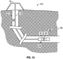
- FIG. 1A illustrates an example logging system for detecting an acoustically reflective boundary in an earth formation in accordance with embodiments of the disclosure.
- the reflective boundaries may be, for example, faults or fractures.
- the fractures may be natural fractures, fractures stimulated by stimulation activities (e.g., hydraulic fracturing), or a combination. Figures are not drawn to scale.
- FIG. 1A illustrates a tool 10 conveyed in a borehole intersecting a formation 80 on tool string 100.
- the borehole 40 may be filled with a downhole fluid 60.
- the borehole 40 may be cased or open.
- the tool 10 may contain a sensor assembly 90, including one or more sensors for detecting the reflective boundary such as, for example, one or more acoustic transmitters and receivers. These sensors may include at least one multipole acoustic transmitter and at least one acoustic receiver.
- the tool 10 may be configured to transmit an acoustic signal into the borehole using the acoustic transmitter, and receive acoustic signals including shear wave signals generated from shear body waves reflected in the formation in a near-field region of the formation around the borehole using the receiver.
- the shear body waves are reflected from the high-incidence reflective boundary (e.g., fault) 50.
- One or more of the sensors may be configured for evaluation of the borehole or the formation according to known techniques, for taking measurements indicative of drilling parameters, borehole properties, formation properties, telemetry or for other parameters of interest.
- Sensor assembly 90 may be contained in a single tool or distributed about the tool string, the surface, or at other locations in the borehole or the formation.
- the system 101 may include a conventional derrick 70.
- a conveyance device (“carrier”) 15, which may be rigid or non-rigid, may be configured to convey the downhole tool 10 into wellbore 40 in proximity to formation 80.
- the conveyance device 15 may be a drill string, coiled tubing, a slickline, an e-line, a wireline, etc.
- the conveyance device 15 may be a stimulation string.
- Downhole tool 10 may be coupled or combined with additional tools.
- the tool 10 may be used during drilling and / or after the wellbore (borehole) 40 has been formed, and may be used in a cased borehole before and / or after fracturing operations (e.g., fracking, refracking) in an interval of the borehole.
- fracturing operations e.g., fracking, refracking
- the conveyance device 15 may include embedded conductors for power and / or data for providing signal and / or power communication between the surface and downhole equipment.
- the conveyance device 15 may include a bottom hole assembly, which may include a drilling motor for rotating a drill bit to extend (drill) the borehole, and a system for circulating a suitable drilling fluid (also referred to as the "mud") under pressure.
- a drilling motor for rotating a drill bit to extend (drill) the borehole
- a system for circulating a suitable drilling fluid also referred to as the "mud" under pressure.
- mud also referred to as the "mud”
- Delay may limit the value of information gained from the sensors, because, among other things, modification of drilling operations or the mud program is not timely with respect to the information extracted. Control of these devices, and of the various processes of the drilling system generally, may be carried out in a completely automated fashion or through interaction with personnel via notifications, graphical representations, user interfaces and the like. Reference information accessible to the processor may also be used.
- the system 101 may be configured as a hydraulic stimulation system.
- stimulation may include any injection of a fluid into a formation.
- An exemplary stimulation system may be configured as a cased or open-hole system for initiating fractures and/or stimulating existing fractures in the formation.
- the tool 10 is conveyed in the formation 80 via a cased borehole both prior to and after a fracturing operation to evaluate the fracturing operation.
- FIG. 1B illustrates a stimulation system in accordance with embodiments of the present disclosure.
- the system 103 includes a downhole tool string 110, such as a stimulation string, wireline, or other carrier conveyed in a borehole 140 surrounded by casing 118.
- the system 103 is configured as a hydraulic stimulation system, but may also configured for additional functions such as hydrocarbon production, evaluation of the formation, evaluation of the borehole, and so on.
- stimulation may include any injection of a fluid into a formation.
- An exemplary stimulation system may be configured as a cased or open hole system for initiating fractures and/or stimulating existing fractures in the formation.
- a fluid may be any flowable substance.
- the tool string 110 may include one or more tools or components to facilitate stimulation of the formation 180.
- the tool string 110 may include a fracturing assembly 120 including, e.g., injection nozzles and mechanical valve devices (e.g., fracturing sleeves, drop-ball devices, and so on).
- the tool string 110 may include a perforation assembly 122.
- the tool string 110 may include additional components, such as one or more isolation components 124 (e.g., packer subs, frangible barriers, etc.).
- Subs may include one or more processors or associated electronics configured to communicate with a surface processing unit and/or control the respective component or assembly.
- the system 103 may be a hydraulic fracturing system that includes an injection device 130 (e.g., a high pressure pump 130) in fluid communication with a fluid source 150.
- the injection device 130 injects fluid into the string 110 to introduce fluid into the formation 180.
- Measurement and control devices including one or more sensors responsive to pumping parameters, may be included for monitoring and control of the respective operation (e.g., hydraulic fracturing or other stimulation).
- Systems 101 and 103 as described in FIGS. 1A & 1B may include a hardware environment operationally coupled (via wired or wireless communication) with the downhole tool 10, other components of the tool string 10, 110, and / or distributed sensors.
- This hardware environment may enable controlling and acquiring information from system components.
- information as used herein includes any form of information (acoustic, analog, digital, EM, printed, etc.), and may include one or more of: raw data, processed data, and signals.
- some embodiments of the present disclosure may be implemented with a hardware environment that includes an information processor 11, an information storage medium 13, an input device 17, processor memory 19, and may include peripheral information storage medium 9.
- the hardware environment may be in the well (e.g., a downhole controller), at the rig (e.g., a surface controller), or at a remote location. Moreover, the several components of the hardware environment may be distributed among those locations.
- the input device 17 may be any data reader or user input device, such as data card reader, keyboard, USB port, etc.
- the information storage medium 13 stores information provided by the detectors.
- Information storage medium 13 may include any non-transitory computer-readable medium for standard computer information storage, such as a USB drive, memory stick, hard disk, removable RAM, EPROMs, EAROMs, flash memories and optical disks or other commonly used memory storage system known to one of ordinary skill in the art including Internet based storage.
- Information storage medium 13 stores a program including machine- readable computer program instructions that when executed cause information processor 11 to execute the disclosed method.
- Information storage medium 13 may also store the formation information provided by the user, or the formation information may be stored in a peripheral information storage medium 9, which may be any standard computer information storage device, such as a USB drive, memory stick, hard disk, removable RAM, or other commonly used memory storage system known to one of ordinary skill in the art including Internet based storage.
- Information processor 11 may be any form of computer or mathematical processing hardware, including Internet based hardware.
- processor memory 19 e.g. computer RAM
- the program when executed, causes information processor 11 to retrieve sensor information from either information storage medium 13 or peripheral information storage medium 9 and process the information to estimate a parameter of interest.
- Information processor 11 may be located on the surface or downhole.
- a surface control unit or processor(s), as described with respect to FIG. 2 may receive signals from downhole sensors and devices and signals from sensors used in the system and process such signals according to programmed instructions provided to the surface control unit.
- the environment may include a control unit in operable communication with pump 130 and various sensors.
- the control unit may be configured to receive, store and/or transmit information generated from the sensors and/or the pump, and control operational parameters responsive to the information.
- the sensors of sensor array 90 may be configured to acquire information relating boundary detection and to the downhole feature(s) of interest.
- the sensors may be in signal communication with a processor via a suitable communication line. It should be understood that the type of sensors used on tool may depend in part on the downhole features to be investigated.
- General embodiments of the present disclosure include methods, devices, and systems for acquiring information relating to the boundary 50.
- One or more of the processors of the system 101 may be configured to estimate properties of the formation 80, such as, for example, location and other characteristics of the boundaries (e.g., fracture 50) such as, for example, fracture orientation, fracture size, fracture intensity, fracture transmissivity, or fracture aperture, using information acquired through sensor array 90.
- the sensors of sensor array 90 may include acoustic, pulsed-neutron, resistivity, radiation, survey, seismic, and imaging sensors. Methods disclosed herein may also include using estimated characteristics of the detected boundaries in performing further operations in the borehole (e.g., drilling, reaming, etc.).
- System 101 may contain formation evaluation sensors or devices (also referred to as measurement-while-drilling ("MWD”) or logging-while-drilling (“LWD”) sensors) determining resistivity, density, porosity, permeability, acoustic properties, nuclear-magnetic resonance properties, formation pressures, properties or characteristics of the fluids downhole and other desired properties of the formation 80.
- MWD measurement-while-drilling
- LWD logging-while-drilling
- system 101 may further include a variety of other sensors, circuitry and processing software and algorithms for providing information about the BHA, drill string, the drill bit and downhole equipment and for determining one or more properties of a bottom hole assembly ("BHA") (such as vibration, bending moment, acceleration, oscillations, whirl, stick-slip, etc.) and drilling operating parameters (such as weight-on-bit, fluid flow rate, pressure, temperature, rate of penetration, azimuth, tool face, drill bit rotation, etc.).
- BHA bottom hole assembly
- drilling operating parameters such as weight-on-bit, fluid flow rate, pressure, temperature, rate of penetration, azimuth, tool face, drill bit rotation, etc.
- the BHA may also include a steering apparatus or tool for steering the drill bit along a desired drilling path, such as force application members activated using electro-mechanical, electro-hydraulic or mud-hydraulic actuators, a bent sub, and the like.
- a steering apparatus or tool for steering the drill bit along a desired drilling path such as force application members activated using electro-mechanical, electro-hydraulic or mud-hydraulic actuators, a bent sub, and the like.
- a point of novelty of the systems illustrated in FIGS. 1A-2 is that at least one processor associated with the systems is configured to perform certain methods (discussed below) that are not in the prior art.
- One or more of the processors of system 101 and 103 may be configured to control sensors as described above and carry out the method of evaluating the earth formation as described in further detail below. Evaluating the formation may include processing the information using at least one processor to detect the boundary 50, including, for example, estimating a location of the boundary 50 (e.g., borehole depth, actual coordinates, orientation, and so on).
- a location of the boundary 50 e.g., borehole depth, actual coordinates, orientation, and so on.
- At least one processor of the system may be configured to use an acoustic monopole and/or multipole (e.g., dipole) transmitters to emit acoustic energy pulses that typically travel radially outwardly from the transmitters and to use at least one acoustic receiver to produce a corresponding signal, responsive to a reflection of an emitted wave.
- One of the processors may also be configured to evaluate the formation from the information corresponding to this signal. In operation, a portion of waves generated by the transmitter reflects from features in the formation causing a response at the receiver. Thus, each receiver produces a response indicative of the formation.
- a processor of the tool directs one or more dipole sources to transmit energy into the borehole and the formation.
- the dipole source may transmit in a direction "x" extending away from the borehole, which is typically perpendicular or substantially perpendicular to the longitudinal axis of the borehole and the tool (the "z" direction).
- Flexural waves are generated that typically can reflect and provide readings out to around 2-4 feet radially into the formation.
- Body waves, which can be reflected back to the borehole, may be detected as signals that are late-arriving and faint relative to reflected flexural wave signals.
- the region around the borehole can be divided into a near-field region that extends laterally (e.g., perpendicular to the borehole axis) to a first distance from the borehole, and a far-field region that extends laterally from the first distance to a second distance.
- the near-field region as defined herein, may mean from the borehole to the furthest distance that flexural waves can extend and return detectable reflected signals.
- Sensor array 90 may include a dipole source that generates two different types of shear body waves in the formation: a vertical shear wave (SV) aligned with the dipole source and polarized in the "x" direction, and a horizontal shear wave (SH) polarized in the "y” direction.
- the dipole source may operate at a frequency of 2-3 kHz. Energy reflected back from these waves can provide information for fractures that, in one embodiment, are oriented such that the angle between the reflecting fracture and the borehole axis (e.g., the z-axis) is greater than 70 degrees.
- the high-incidence processing technique of the present disclosure may use information generated from cross-dipole source.
- the source generates shear body waves that radiate into the formation and are reflected by fractures in the formation.
- the processing technique has a direct wave mode that must be suppressed.
- imaging shear body waves using Deep Shear Wave Imaging is technically infeasible at high-incidence angles. Sufficient resolution for deep imaging is not possible outside the 0 to 60 degree angle range, because imaging points collapse around the borehole as the incidence angle approaches the upper limit. As shown below, however, shear waves may be used to detect boundaries at a region closer to the borehole (e.g., in the near-field).
- FIG. 3 shows the results of simulated near-field shear wave logging measurements at various angles of incidence.
- FIG. 3 illustrates that even at 90 degrees, shear waves reflecting from boundaries in the near field are readily detected at a significant distance along the borehole, although the range away from the borehole where they can be imaged decreases with increase in incidence angle, and in some instances provide sufficient clarity to image the near-borehole segment of the boundary.
- FIG. 3 demonstrates decreasing far-field sensitivity as the angle of incidence increases (e.g., the cone of sensitivity).
- Energy reflected back from these waves can provide sufficient information for fracture high-incidence fracture detection, either alone or in conjunction with traditional far-field waves.
- the information contained in the received near-field signal e.g., in terms of resolution
- the information contained in the received far-field waves corresponding with traditional DSWI increased with decrease in angle incidence, such that any deficiencies in the near-field attributable signal may be compensated by using far-field information.
- Multiple images can be used in combination to determine the presence of natural and hydraulically induced fractures. Monitoring of these fractures can advantageously be used to monitor a reservoir associated with the formation, as well as fracturing effectiveness.
- Measurements may be used to estimate anisotropy and azimuth, which can be used to estimate the location, intensity and strike (azimuth) of natural and/or stimulated fractures. Such information is useful in determining fracture height, length and extent in a formation. For example, in evaluating the results of stimulation operations, shear wave processing can be used to estimate hydraulic fracture height (HFH) and length (HFL), and/or the lateral extent of fractures into the far-field or Stimulated Reservoir Area (SRA).
- HSH hydraulic fracture height
- HFL long-field or Stimulated Reservoir Area
- the processing techniques above can be used in conjunction with other techniques for fracture evaluation, such as ultrasonic imaging, Stoneley permeability analysis, and azimuthal shear-wave anisotropy evaluation from cross-dipole, that typically investigate a limited area around a well, e.g., 2-4 ft.
- FIG. 4 illustrates a method for evaluating an earth formation.
- the method 400 is described in conjunction with a processor that receives information (e.g., signal data) relating to an earth formation with fractures or other reflective boundaries.
- Optional step 405 of the method 500 may include performing a drilling operation in a borehole.
- a drill string may be used to form (e.g., drill) the borehole.
- Optional step 410 may include conveying at least one acoustic sensor in the borehole on a conveyance device.
- Optional step 420 of the method 400 may include emitting a wave.
- step 420 may include emitting a multipole acoustic wave.
- Step 430 is identifying a shear wave signal. Acoustic signals may be measured via hydrophone (i.e., as a pressure pulse).
- Step 430 of the method 400 may include using at least one sensor to produce information responsive to a shear body waves reflected in the formation in a near-field region of the formation around the borehole, wherein the information is indicative of a reflective boundary along the borehole.
- Step 430 may be carried out using processing techniques common in the art such as identifying signal characteristics indicative of the shear body wave, using moveout velocity, and the like.
- Step 440 may include processing the information using at least one processor to estimate a location of the reflective boundary.
- Step 440 may include estimating a depth along the borehole of the boundary based on the shear wave signal.
- Optional step 450 may include evaluating the boundary using at least one attribute of the shear wave signal and the estimated depth.
- Optional step 460 may include controlling the direction of drilling based on the estimated depth of the boundary.
- Optional step 470 may include performing further operations in the formation based on the estimated depth of the boundary. For example, further operations may include producing hydrocarbons, performing well stimulation, casing the borehole, and so on.
- Optional step 480 may include generating a formation fracture model based on the estimated depth of the boundary.
- Optional step 490 may include estimating at least one property of the boundary using an attribute of an identified wave received by the receiver.
- the wave attribute may be an attribute of the shear wave signal.
- attributes of wave signals resulting from at least one of i) a compressional wave; ii) a Stoneley wave; and iii) a guided wave.
- the attribute may include one of amplitude, frequency, duration, decay, and so on.
- attributes of the shear wave signal may be compared against the same attributes of one of the other identified signals.
- FIG. 5 illustrates a method for evaluating fractures in an earth formation.
- the method 500 is described in conjunction with a processor that receives information (e.g., signal data) relating a fracturing operation.
- Optional step 510 may include preparation for stimulation.
- Step 510 may be carried out by selecting one or more zones of the borehole for stimulation, e.g., using various open hole logging operations. This may include, after identifying zones of interest, running casing into the borehole and cementing.
- Optional step 520 of method 500 may include detecting natural fractures in the formation at high incidence to the borehole prior to stimulation by generating acoustic signals from a multipole source, e.g., a dipole source.
- detection of the natural fractures is performed through a cased hole. In another embodiment, detection is performed through an open hole, which may then be cased prior to the stimulation operation.
- detection of high incidence fractures is performed as a logging tool is run through the cased hole.
- Detection of the high-incidence reflector may be performed in the near-field in conjunction with another imaging technique, such as, for example, DSWI used for the far-field.
- DSW information may be used to estimate the azimuth of the strike orientation of natural and hydraulic fractures in the far-field from the wellbore. The amount of anisotropy (variation in a given direction) detected by the DSW imaging gives a measure of fracture intensity, and the azimuth gives the fracture strike direction.
- Step 530 of method 500 may include conducting a stimulation operation in the formation. This may be carried out, for example, by using the system 103 to perforate the borehole and pump fluid into the borehole to hydraulically fracture the formation.
- Step 540 of method 500 repeats detection of high-incidence boundaries after the hydraulic fracturing operation is complete.
- Optional step 550 may include evaluating the effectiveness of the fracturing operation and/or evaluate the formation, e.g., by modeling the formation or improving existing models.
- Post-fracture detection results may be compared with the pre-fracture detection results, for example.
- post-fracture imaging results may be compared with the pre-fracture imaging results. At least one of the post-fracture detection and post-fracture imaging is used to calculate the hydraulic fracture height (HFH) and length (HFL) and Stimulated Rock Area (SRA).
- the location, orientation and magnitude of fractures in the formation can be evaluated in both the far-field and near-field around the borehole. Additional measurements of reflected guided waves, compression waves, and Stoneley waves may also be used in combination with these measurements to provide a more complete picture of the fracture intensity and complexity before and after fracturing, and thus provides a more complete evaluation of the effectiveness of the fracturing operation.
- the measurements may be used to generate or improve a model of the formation and/or fractures, such as a discrete fracture network (DFN) model, geological model or other mathematical model of the formation. For example, images taken before and after the fracturing operation are used to re-evaluate geomechanical properties of the formation and/or create new models.
- DFN discrete fracture network
- the strike orientation and azimuth estimated from the pre-fracturing and/or post-fracturing measurements are evaluated to estimate the number and extent of natural fractures and/or stimulated fractures. This information may be used to evaluate the effectiveness of the fracturing operation and/or make adjustments to subsequent fracturing operations.
- Shear wave boundary detection pre-and-post fracture results may be used in Fracture Stimulation Modeling and Design as part of the planning phase for wellbore completions.
- Such planning includes predicting hydraulic fracture height as well as fracture length and/or stimulated reservoir area away from the borehole.
- aspects of the present disclosure may be implemented using techniques known in the art an adapted to use with near-field shear wave signals or with mixed near- and far-field signals, described in patent applications US 2015/0013974 to Mekic et al , US 2015/00109886 to Mekic et al , and US 2008/0151690 to Tang et al.
- conveyance device means any device, device component, combination of devices, media and/or member that may be used to convey, house, support or otherwise facilitate the use of another device, device component, combination of devices, media and/or member.
- exemplary non-limiting conveyance devices include drill strings of the coiled tube type, of the jointed pipe type and any combination or portion thereof.
- Other conveyance device examples include casing pipes, wirelines, wire line sondes, slickline sondes, drop shots, downhole subs, BHA's, drill string inserts, modules, tractors, internal housings and substrate portions thereof, and self-propelled tractors.
- a processor is any information processing device that transmits, receives, manipulates, converts, calculates, modulates, transposes, carries, stores, or otherwise utilizes information.
- an information processing device includes a computer that executes programmed instructions for performing various methods. These instructions may provide for equipment operation, control, data collection and analysis and other functions in addition to the functions described in this disclosure.
- the processor may execute instructions stored in computer memory accessible to the processor, or may employ logic implemented as field-programmable gate arrays ('FPGAs'), application-specific integrated circuits ('ASICs'), other combinatorial or sequential logic hardware, and so on.
- An information processing device may include a processor, resident memory, and peripherals for executing programmed instructions.
- estimation of the parameter of interest may involve applying a model.
- the model may include, but is not limited to, (i) a mathematical equation, (ii) an algorithm, (iii) a database of associated parameters, (iv) an array, or a combination thereof which describes physical characteristics of the downhole cuttings in relation to information received by the sensors described herein.
- fluid refers to one or more gasses, one or more liquids, and mixtures thereof.
- High-incidence as used herein may mean relating to an orientation of formation elements such that the angle between the reflecting fracture and the borehole axis is greater than 60 degrees.
- a "downhole fluid” as used herein includes any gas, liquid, flowable solid and other materials having a fluid property, and relating to hydrocarbon recovery.
- a downhole fluid may be natural or man-made and may be transported downhole or may be recovered from a downhole location.
- Non-limiting examples of downhole fluids include drilling fluids, return fluids, formation fluids, production fluids containing one or more hydrocarbons, oils and solvents used in conjunction with downhole tools, water, brine, and combinations thereof.
Landscapes
- Physics & Mathematics (AREA)
- Life Sciences & Earth Sciences (AREA)
- Engineering & Computer Science (AREA)
- Geology (AREA)
- Remote Sensing (AREA)
- Environmental & Geological Engineering (AREA)
- General Life Sciences & Earth Sciences (AREA)
- Geophysics (AREA)
- Acoustics & Sound (AREA)
- General Physics & Mathematics (AREA)
- Mining & Mineral Resources (AREA)
- Fluid Mechanics (AREA)
- Geochemistry & Mineralogy (AREA)
- Geophysics And Detection Of Objects (AREA)
- Investigating Or Analyzing Materials By The Use Of Ultrasonic Waves (AREA)
Claims (9)
- Procédé pour évaluer une formation terrestre (80) croisée par un trou de forage (40), comprenant :la détection d'une limite réfléchissante (50) dans la formation terrestre (80) à l'aide d'au moins un processeur (11) pour :générer un signal acoustique multipolaire avec un outil acoustique (10) dans le trou de forage (40) ;identifier un signal d'onde de cisaillement résultant d'ondes de volume de cisaillement réfléchies depuis la limite réfléchissante (50) dans la formation (80) dans une région de champ proche de la formation (80) autour du trou de forage (40) en réponse au signal acoustique multipolaire généré ; etestimer au moins une profondeur le long du trou de forage (40) de la limite (50) en fonction du signal d'onde de cisaillement.
- Procédé selon la revendication 1, dans lequel la limite (50) comprend au moins l'un de i) une fracture ; ii) un défaut ; et iii) a un angle d'incidence par rapport à un axe longitudinal du trou de forage (40) supérieur à 70 degrés.
- Procédé selon la revendication 1, comprenant la génération d'ondes de cisaillement dans la région de champ proche à l'aide d'un émetteur à dipôles croisés.
- Procédé selon la revendication 1, dans lequel l'outil acoustique (10) est transporté sur un train de tiges de forage, le procédé comprenant la détection de la limite réfléchissante (50) pendant des opérations de forage.
- Procédé selon la revendication 1, comprenant la réalisation de l'un de ce qui suit en fonction de la profondeur estimée de la limite (50) : i) l'exécution d'autres opérations dans la formation (80) ; ii) la génération d'un modèle de fracture de formation.
- Procédé selon la revendication 1, comprenant en outre l'estimation d'au moins une propriété de la limite (50) à l'aide d'un autre signal résultant d'au moins l'une de i) une onde de compression ; ii) une onde de Stoneley ; et iii) une onde guidée.
- Procédé selon la revendication 1, comprenant l'utilisation de données supplémentaires et de la profondeur pour estimer au moins l'un de : i) un emplacement et une orientation de la limite (50) ; et ii) un azimut de rencontre de la limite (50).
- Appareil pour évaluer une formation terrestre (80) croisée par un trou de forage (40), comprenant :un outil acoustique (10) configuré pour être transporté dans le trou de forage (40) sur un support (15), l'outil acoustique (10) incluant au moins un émetteur acoustique multipolaire et au moins un récepteur acoustique multipolaire ; etau moins un processeur (11) configuré pour détecter une limite réfléchissante (50) dans la formation terrestre (80) au moyen de :la génération d'un signal acoustique multipolaire avec l'outil acoustique (10) dans le trou de forage (40) ;l'identification d'un signal d'onde de cisaillement reçu par le récepteur acoustique résultant d'ondes de volume de cisaillement réfléchies depuis la limite réfléchissante (50) dans la formation (80) dans une région de champ proche de la formation (80) autour du trou de forage (40) en réponse au signal acoustique multipolaire généré ; etl'estimation d'au moins une profondeur le long du trou de forage (40) de la limite (50) en fonction du signal d'onde de cisaillement.
- Appareil selon la revendication 8, dans lequel l'au moins un processeur (11) est configuré pour détecter la limite réfléchissante (50) lorsque la limite (50) a un angle d'incidence par rapport à un axe longitudinal du trou de forage (40) supérieur à 70 degrés.
Applications Claiming Priority (3)
| Application Number | Priority Date | Filing Date | Title |
|---|---|---|---|
| US201562173873P | 2015-06-10 | 2015-06-10 | |
| US15/178,290 US10302792B2 (en) | 2015-06-10 | 2016-06-09 | Detection of high incident reflective boundaries using near-field shear waves |
| PCT/US2016/036842 WO2016201192A1 (fr) | 2015-06-10 | 2016-06-10 | Détection de limites réfléchissantes d'incidence élevée à l'aide d'ondes de cisaillement en champ proche |
Publications (3)
| Publication Number | Publication Date |
|---|---|
| EP3307986A1 EP3307986A1 (fr) | 2018-04-18 |
| EP3307986A4 EP3307986A4 (fr) | 2019-03-13 |
| EP3307986B1 true EP3307986B1 (fr) | 2021-08-11 |
Family
ID=57504078
Family Applications (1)
| Application Number | Title | Priority Date | Filing Date |
|---|---|---|---|
| EP16808351.7A Active EP3307986B1 (fr) | 2015-06-10 | 2016-06-10 | Détection de frontières réflectrices à l'aide d'ondes de cisaillement en champ proche |
Country Status (5)
| Country | Link |
|---|---|
| US (1) | US10302792B2 (fr) |
| EP (1) | EP3307986B1 (fr) |
| BR (1) | BR112017025871B1 (fr) |
| SA (1) | SA517390470B1 (fr) |
| WO (1) | WO2016201192A1 (fr) |
Families Citing this family (4)
| Publication number | Priority date | Publication date | Assignee | Title |
|---|---|---|---|---|
| US10648329B2 (en) | 2017-04-10 | 2020-05-12 | Baker Hughes, A Ge Company, Llc | Estimation of fracture properties based on borehole fluid data and acoustic imaging |
| EP3660543B1 (fr) * | 2018-11-27 | 2024-03-13 | Baker Hughes Holdings LLC | Modèle de rayon de fracture tridimensionnel |
| US11513254B2 (en) * | 2019-01-10 | 2022-11-29 | Baker Hughes Oilfield Operations Llc | Estimation of fracture properties based on borehole fluid data, acoustic shear wave imaging and well bore imaging |
| US11460446B2 (en) | 2020-04-21 | 2022-10-04 | Baker Hughes Oilfield Operations Llc | Estimation of formation and/or downhole component properties using electromagnetic acoustic sensing |
Family Cites Families (17)
| Publication number | Priority date | Publication date | Assignee | Title |
|---|---|---|---|---|
| US3764968A (en) | 1972-06-15 | 1973-10-09 | Schlumberger Technology Corp | Well bore data transmission apparatus with debris clearing apparatus |
| US3958217A (en) | 1974-05-10 | 1976-05-18 | Teleco Inc. | Pilot operated mud-pulse valve |
| US4351037A (en) | 1977-12-05 | 1982-09-21 | Scherbatskoy Serge Alexander | Systems, apparatus and methods for measuring while drilling |
| US4953595A (en) | 1987-07-29 | 1990-09-04 | Eastman Christensen Company | Mud pulse valve and method of valving in a mud flow for sharper rise and fall times, faster data pulse rates, and longer lifetime of the mud pulse valve |
| US5402392A (en) * | 1993-08-10 | 1995-03-28 | Exxon Production Research Company | Determining orientation of vertical fractures with well logging tools |
| US6614360B1 (en) * | 1995-01-12 | 2003-09-02 | Baker Hughes Incorporated | Measurement-while-drilling acoustic system employing multiple, segmented transmitters and receivers |
| US7417920B2 (en) | 2001-03-13 | 2008-08-26 | Baker Hughes Incorporated | Reciprocating pulser for mud pulse telemetry |
| US6898150B2 (en) | 2001-03-13 | 2005-05-24 | Baker Hughes Incorporated | Hydraulically balanced reciprocating pulser valve for mud pulse telemetry |
| US7035165B2 (en) | 2003-01-29 | 2006-04-25 | Baker Hughes Incorporated | Imaging near-borehole structure using directional acoustic-wave measurement |
| CA2676123A1 (fr) | 2006-12-26 | 2008-07-10 | Baker Hughes Incorporated | Imagerie de reflecteurs proches du trou de forage au moyen de reflexions d'onde de cisaillement d'un outil acoustique a composants multiples |
| WO2008157366A2 (fr) | 2007-06-15 | 2008-12-24 | Baker Hughes Incorporated | Imagerie d'une structure de formation devant le trépan |
| US20110122727A1 (en) * | 2007-07-06 | 2011-05-26 | Gleitman Daniel D | Detecting acoustic signals from a well system |
| US20090205899A1 (en) | 2008-02-19 | 2009-08-20 | Baker Hughes Incorporated | Acoustic Imaging Away From the Borehole Using a Low-Frequency Quadrupole Excitation |
| US9063251B2 (en) * | 2010-12-27 | 2015-06-23 | Baker Hughes Incorporated | Stress in formations from azimuthal variation in acoustic and other properties |
| AU2012271016B2 (en) * | 2011-06-13 | 2014-12-04 | Shell Internationale Research Maatschappij B.V. | Hydraulic fracture monitoring using active seismic sources with receivers in the treatment well |
| US9670770B2 (en) * | 2013-06-24 | 2017-06-06 | Baker Hughes Incorporated | Fracture evaluation through cased boreholes |
| WO2015061305A1 (fr) | 2013-10-21 | 2015-04-30 | Baker Hughes Incorporated | Imagerie par onde acoustique de formations |
-
2016
- 2016-06-09 US US15/178,290 patent/US10302792B2/en active Active
- 2016-06-10 BR BR112017025871-4A patent/BR112017025871B1/pt active IP Right Grant
- 2016-06-10 WO PCT/US2016/036842 patent/WO2016201192A1/fr active Application Filing
- 2016-06-10 EP EP16808351.7A patent/EP3307986B1/fr active Active
-
2017
- 2017-12-03 SA SA517390470A patent/SA517390470B1/ar unknown
Also Published As
| Publication number | Publication date |
|---|---|
| EP3307986A1 (fr) | 2018-04-18 |
| BR112017025871A2 (pt) | 2018-08-14 |
| US20160363684A1 (en) | 2016-12-15 |
| BR112017025871B1 (pt) | 2022-10-04 |
| WO2016201192A1 (fr) | 2016-12-15 |
| SA517390470B1 (ar) | 2022-12-05 |
| EP3307986A4 (fr) | 2019-03-13 |
| US10302792B2 (en) | 2019-05-28 |
Similar Documents
| Publication | Publication Date | Title |
|---|---|---|
| US9670770B2 (en) | Fracture evaluation through cased boreholes | |
| US10465509B2 (en) | Collocated multitone acoustic beam and electromagnetic flux leakage evaluation downhole | |
| US11513254B2 (en) | Estimation of fracture properties based on borehole fluid data, acoustic shear wave imaging and well bore imaging | |
| US10444389B2 (en) | Determining change in permeability caused by a hydraulic fracture in reservoirs | |
| US9238942B2 (en) | System and method for stress field based wellbore steering | |
| US10823868B2 (en) | Estimating depth-dependent lateral tectonic strain profiles | |
| US7301852B2 (en) | Methods of generating directional low frequency acoustic signals and reflected signal detection enhancements for seismic while drilling applications | |
| US9885795B2 (en) | Acoustic wave imaging of formations | |
| US11119239B2 (en) | Measuring petrophysical properties of an earth formation by regularized direct inversion of electromagnetic signals | |
| US10782433B2 (en) | Method for an automatic detection of acoustic reflectors and their parameters from borehole acoustic array data | |
| EP3063367B1 (fr) | Analyse in situ de déblais de fond de trou | |
| US10605944B2 (en) | Formation acoustic property measurement with beam-angled transducer array | |
| EP3307986B1 (fr) | Détection de frontières réflectrices à l'aide d'ondes de cisaillement en champ proche | |
| US11774631B2 (en) | Geologic formation neutron porosity system | |
| WO2016209822A1 (fr) | Prédiction d'une propagation d'une fracture hydraulique | |
| US20240069239A1 (en) | Methods using dual arrival compressional and shear arrival events in layered formations for formation evaluation, geomechanics, well placement, and completion design | |
| WO2024036334A1 (fr) | Caractérisation de fractures pendant le forage |
Legal Events
| Date | Code | Title | Description |
|---|---|---|---|
| STAA | Information on the status of an ep patent application or granted ep patent |
Free format text: STATUS: THE INTERNATIONAL PUBLICATION HAS BEEN MADE |
|
| PUAI | Public reference made under article 153(3) epc to a published international application that has entered the european phase |
Free format text: ORIGINAL CODE: 0009012 |
|
| STAA | Information on the status of an ep patent application or granted ep patent |
Free format text: STATUS: REQUEST FOR EXAMINATION WAS MADE |
|
| 17P | Request for examination filed |
Effective date: 20180105 |
|
| AK | Designated contracting states |
Kind code of ref document: A1 Designated state(s): AL AT BE BG CH CY CZ DE DK EE ES FI FR GB GR HR HU IE IS IT LI LT LU LV MC MK MT NL NO PL PT RO RS SE SI SK SM TR |
|
| AX | Request for extension of the european patent |
Extension state: BA ME |
|
| DAV | Request for validation of the european patent (deleted) | ||
| DAX | Request for extension of the european patent (deleted) | ||
| REG | Reference to a national code |
Ref country code: DE Ref legal event code: R079 Ref document number: 602016062098 Country of ref document: DE Free format text: PREVIOUS MAIN CLASS: E21B0047000000 Ipc: G01V0001460000 |
|
| A4 | Supplementary search report drawn up and despatched |
Effective date: 20190213 |
|
| RIC1 | Information provided on ipc code assigned before grant |
Ipc: G01V 1/46 20060101AFI20190207BHEP Ipc: G01V 1/50 20060101ALI20190207BHEP Ipc: G01V 1/28 20060101ALI20190207BHEP |
|
| GRAP | Despatch of communication of intention to grant a patent |
Free format text: ORIGINAL CODE: EPIDOSNIGR1 |
|
| STAA | Information on the status of an ep patent application or granted ep patent |
Free format text: STATUS: GRANT OF PATENT IS INTENDED |
|
| INTG | Intention to grant announced |
Effective date: 20210304 |
|
| RAP3 | Party data changed (applicant data changed or rights of an application transferred) |
Owner name: BAKER HUGHES HOLDINGS LLC |
|
| GRAS | Grant fee paid |
Free format text: ORIGINAL CODE: EPIDOSNIGR3 |
|
| GRAA | (expected) grant |
Free format text: ORIGINAL CODE: 0009210 |
|
| STAA | Information on the status of an ep patent application or granted ep patent |
Free format text: STATUS: THE PATENT HAS BEEN GRANTED |
|
| AK | Designated contracting states |
Kind code of ref document: B1 Designated state(s): AL AT BE BG CH CY CZ DE DK EE ES FI FR GB GR HR HU IE IS IT LI LT LU LV MC MK MT NL NO PL PT RO RS SE SI SK SM TR |
|
| REG | Reference to a national code |
Ref country code: CH Ref legal event code: EP |
|
| REG | Reference to a national code |
Ref country code: DE Ref legal event code: R096 Ref document number: 602016062098 Country of ref document: DE |
|
| REG | Reference to a national code |
Ref country code: IE Ref legal event code: FG4D Ref country code: AT Ref legal event code: REF Ref document number: 1419953 Country of ref document: AT Kind code of ref document: T Effective date: 20210915 |
|
| REG | Reference to a national code |
Ref country code: LT Ref legal event code: MG9D |
|
| REG | Reference to a national code |
Ref country code: NL Ref legal event code: MP Effective date: 20210811 |
|
| REG | Reference to a national code |
Ref country code: AT Ref legal event code: MK05 Ref document number: 1419953 Country of ref document: AT Kind code of ref document: T Effective date: 20210811 |
|
| REG | Reference to a national code |
Ref country code: NO Ref legal event code: T2 Effective date: 20210811 |
|
| PG25 | Lapsed in a contracting state [announced via postgrant information from national office to epo] |
Ref country code: RS Free format text: LAPSE BECAUSE OF FAILURE TO SUBMIT A TRANSLATION OF THE DESCRIPTION OR TO PAY THE FEE WITHIN THE PRESCRIBED TIME-LIMIT Effective date: 20210811 Ref country code: SE Free format text: LAPSE BECAUSE OF FAILURE TO SUBMIT A TRANSLATION OF THE DESCRIPTION OR TO PAY THE FEE WITHIN THE PRESCRIBED TIME-LIMIT Effective date: 20210811 Ref country code: PT Free format text: LAPSE BECAUSE OF FAILURE TO SUBMIT A TRANSLATION OF THE DESCRIPTION OR TO PAY THE FEE WITHIN THE PRESCRIBED TIME-LIMIT Effective date: 20211213 Ref country code: HR Free format text: LAPSE BECAUSE OF FAILURE TO SUBMIT A TRANSLATION OF THE DESCRIPTION OR TO PAY THE FEE WITHIN THE PRESCRIBED TIME-LIMIT Effective date: 20210811 Ref country code: ES Free format text: LAPSE BECAUSE OF FAILURE TO SUBMIT A TRANSLATION OF THE DESCRIPTION OR TO PAY THE FEE WITHIN THE PRESCRIBED TIME-LIMIT Effective date: 20210811 Ref country code: FI Free format text: LAPSE BECAUSE OF FAILURE TO SUBMIT A TRANSLATION OF THE DESCRIPTION OR TO PAY THE FEE WITHIN THE PRESCRIBED TIME-LIMIT Effective date: 20210811 Ref country code: AT Free format text: LAPSE BECAUSE OF FAILURE TO SUBMIT A TRANSLATION OF THE DESCRIPTION OR TO PAY THE FEE WITHIN THE PRESCRIBED TIME-LIMIT Effective date: 20210811 Ref country code: BG Free format text: LAPSE BECAUSE OF FAILURE TO SUBMIT A TRANSLATION OF THE DESCRIPTION OR TO PAY THE FEE WITHIN THE PRESCRIBED TIME-LIMIT Effective date: 20211111 Ref country code: LT Free format text: LAPSE BECAUSE OF FAILURE TO SUBMIT A TRANSLATION OF THE DESCRIPTION OR TO PAY THE FEE WITHIN THE PRESCRIBED TIME-LIMIT Effective date: 20210811 |
|
| PG25 | Lapsed in a contracting state [announced via postgrant information from national office to epo] |
Ref country code: PL Free format text: LAPSE BECAUSE OF FAILURE TO SUBMIT A TRANSLATION OF THE DESCRIPTION OR TO PAY THE FEE WITHIN THE PRESCRIBED TIME-LIMIT Effective date: 20210811 Ref country code: LV Free format text: LAPSE BECAUSE OF FAILURE TO SUBMIT A TRANSLATION OF THE DESCRIPTION OR TO PAY THE FEE WITHIN THE PRESCRIBED TIME-LIMIT Effective date: 20210811 Ref country code: GR Free format text: LAPSE BECAUSE OF FAILURE TO SUBMIT A TRANSLATION OF THE DESCRIPTION OR TO PAY THE FEE WITHIN THE PRESCRIBED TIME-LIMIT Effective date: 20211112 |
|
| PG25 | Lapsed in a contracting state [announced via postgrant information from national office to epo] |
Ref country code: NL Free format text: LAPSE BECAUSE OF FAILURE TO SUBMIT A TRANSLATION OF THE DESCRIPTION OR TO PAY THE FEE WITHIN THE PRESCRIBED TIME-LIMIT Effective date: 20210811 |
|
| PG25 | Lapsed in a contracting state [announced via postgrant information from national office to epo] |
Ref country code: DK Free format text: LAPSE BECAUSE OF FAILURE TO SUBMIT A TRANSLATION OF THE DESCRIPTION OR TO PAY THE FEE WITHIN THE PRESCRIBED TIME-LIMIT Effective date: 20210811 |
|
| REG | Reference to a national code |
Ref country code: DE Ref legal event code: R097 Ref document number: 602016062098 Country of ref document: DE |
|
| PG25 | Lapsed in a contracting state [announced via postgrant information from national office to epo] |
Ref country code: SM Free format text: LAPSE BECAUSE OF FAILURE TO SUBMIT A TRANSLATION OF THE DESCRIPTION OR TO PAY THE FEE WITHIN THE PRESCRIBED TIME-LIMIT Effective date: 20210811 Ref country code: SK Free format text: LAPSE BECAUSE OF FAILURE TO SUBMIT A TRANSLATION OF THE DESCRIPTION OR TO PAY THE FEE WITHIN THE PRESCRIBED TIME-LIMIT Effective date: 20210811 Ref country code: RO Free format text: LAPSE BECAUSE OF FAILURE TO SUBMIT A TRANSLATION OF THE DESCRIPTION OR TO PAY THE FEE WITHIN THE PRESCRIBED TIME-LIMIT Effective date: 20210811 Ref country code: EE Free format text: LAPSE BECAUSE OF FAILURE TO SUBMIT A TRANSLATION OF THE DESCRIPTION OR TO PAY THE FEE WITHIN THE PRESCRIBED TIME-LIMIT Effective date: 20210811 Ref country code: CZ Free format text: LAPSE BECAUSE OF FAILURE TO SUBMIT A TRANSLATION OF THE DESCRIPTION OR TO PAY THE FEE WITHIN THE PRESCRIBED TIME-LIMIT Effective date: 20210811 Ref country code: AL Free format text: LAPSE BECAUSE OF FAILURE TO SUBMIT A TRANSLATION OF THE DESCRIPTION OR TO PAY THE FEE WITHIN THE PRESCRIBED TIME-LIMIT Effective date: 20210811 |
|
| PLBE | No opposition filed within time limit |
Free format text: ORIGINAL CODE: 0009261 |
|
| STAA | Information on the status of an ep patent application or granted ep patent |
Free format text: STATUS: NO OPPOSITION FILED WITHIN TIME LIMIT |
|
| 26N | No opposition filed |
Effective date: 20220512 |
|
| PG25 | Lapsed in a contracting state [announced via postgrant information from national office to epo] |
Ref country code: IT Free format text: LAPSE BECAUSE OF FAILURE TO SUBMIT A TRANSLATION OF THE DESCRIPTION OR TO PAY THE FEE WITHIN THE PRESCRIBED TIME-LIMIT Effective date: 20210811 |
|
| PG25 | Lapsed in a contracting state [announced via postgrant information from national office to epo] |
Ref country code: SI Free format text: LAPSE BECAUSE OF FAILURE TO SUBMIT A TRANSLATION OF THE DESCRIPTION OR TO PAY THE FEE WITHIN THE PRESCRIBED TIME-LIMIT Effective date: 20210811 |
|
| REG | Reference to a national code |
Ref country code: DE Ref legal event code: R119 Ref document number: 602016062098 Country of ref document: DE |
|
| PG25 | Lapsed in a contracting state [announced via postgrant information from national office to epo] |
Ref country code: MC Free format text: LAPSE BECAUSE OF FAILURE TO SUBMIT A TRANSLATION OF THE DESCRIPTION OR TO PAY THE FEE WITHIN THE PRESCRIBED TIME-LIMIT Effective date: 20210811 |
|
| REG | Reference to a national code |
Ref country code: CH Ref legal event code: PL |
|
| REG | Reference to a national code |
Ref country code: BE Ref legal event code: MM Effective date: 20220630 |
|
| PG25 | Lapsed in a contracting state [announced via postgrant information from national office to epo] |
Ref country code: LU Free format text: LAPSE BECAUSE OF NON-PAYMENT OF DUE FEES Effective date: 20220610 Ref country code: LI Free format text: LAPSE BECAUSE OF NON-PAYMENT OF DUE FEES Effective date: 20220630 Ref country code: IE Free format text: LAPSE BECAUSE OF NON-PAYMENT OF DUE FEES Effective date: 20220610 Ref country code: FR Free format text: LAPSE BECAUSE OF NON-PAYMENT OF DUE FEES Effective date: 20220630 Ref country code: CH Free format text: LAPSE BECAUSE OF NON-PAYMENT OF DUE FEES Effective date: 20220630 |
|
| PG25 | Lapsed in a contracting state [announced via postgrant information from national office to epo] |
Ref country code: DE Free format text: LAPSE BECAUSE OF NON-PAYMENT OF DUE FEES Effective date: 20230103 Ref country code: BE Free format text: LAPSE BECAUSE OF NON-PAYMENT OF DUE FEES Effective date: 20220630 |
|
| P01 | Opt-out of the competence of the unified patent court (upc) registered |
Effective date: 20230526 |
|
| PGFP | Annual fee paid to national office [announced via postgrant information from national office to epo] |
Ref country code: NO Payment date: 20230525 Year of fee payment: 8 |
|
| PGFP | Annual fee paid to national office [announced via postgrant information from national office to epo] |
Ref country code: GB Payment date: 20230523 Year of fee payment: 8 |
|
| PG25 | Lapsed in a contracting state [announced via postgrant information from national office to epo] |
Ref country code: HU Free format text: LAPSE BECAUSE OF FAILURE TO SUBMIT A TRANSLATION OF THE DESCRIPTION OR TO PAY THE FEE WITHIN THE PRESCRIBED TIME-LIMIT; INVALID AB INITIO Effective date: 20160610 |
|
| PG25 | Lapsed in a contracting state [announced via postgrant information from national office to epo] |
Ref country code: MK Free format text: LAPSE BECAUSE OF FAILURE TO SUBMIT A TRANSLATION OF THE DESCRIPTION OR TO PAY THE FEE WITHIN THE PRESCRIBED TIME-LIMIT Effective date: 20210811 Ref country code: CY Free format text: LAPSE BECAUSE OF FAILURE TO SUBMIT A TRANSLATION OF THE DESCRIPTION OR TO PAY THE FEE WITHIN THE PRESCRIBED TIME-LIMIT Effective date: 20210811 |