EP3307695B1 - Refractories for applications in combustion chambers intended for producing energy and/or waste disposal - Google Patents
Refractories for applications in combustion chambers intended for producing energy and/or waste disposal Download PDFInfo
- Publication number
- EP3307695B1 EP3307695B1 EP15744663.4A EP15744663A EP3307695B1 EP 3307695 B1 EP3307695 B1 EP 3307695B1 EP 15744663 A EP15744663 A EP 15744663A EP 3307695 B1 EP3307695 B1 EP 3307695B1
- Authority
- EP
- European Patent Office
- Prior art keywords
- layer
- refractory
- refractory material
- weight
- homogeneous
- Prior art date
- Legal status (The legal status is an assumption and is not a legal conclusion. Google has not performed a legal analysis and makes no representation as to the accuracy of the status listed.)
- Active
Links
Images

Classifications
-
- C—CHEMISTRY; METALLURGY
- C04—CEMENTS; CONCRETE; ARTIFICIAL STONE; CERAMICS; REFRACTORIES
- C04B—LIME, MAGNESIA; SLAG; CEMENTS; COMPOSITIONS THEREOF, e.g. MORTARS, CONCRETE OR LIKE BUILDING MATERIALS; ARTIFICIAL STONE; CERAMICS; REFRACTORIES; TREATMENT OF NATURAL STONE
- C04B35/00—Shaped ceramic products characterised by their composition; Ceramics compositions; Processing powders of inorganic compounds preparatory to the manufacturing of ceramic products
- C04B35/01—Shaped ceramic products characterised by their composition; Ceramics compositions; Processing powders of inorganic compounds preparatory to the manufacturing of ceramic products based on oxide ceramics
- C04B35/10—Shaped ceramic products characterised by their composition; Ceramics compositions; Processing powders of inorganic compounds preparatory to the manufacturing of ceramic products based on oxide ceramics based on aluminium oxide
- C04B35/101—Refractories from grain sized mixtures
-
- B—PERFORMING OPERATIONS; TRANSPORTING
- B32—LAYERED PRODUCTS
- B32B—LAYERED PRODUCTS, i.e. PRODUCTS BUILT-UP OF STRATA OF FLAT OR NON-FLAT, e.g. CELLULAR OR HONEYCOMB, FORM
- B32B18/00—Layered products essentially comprising ceramics, e.g. refractory products
-
- C—CHEMISTRY; METALLURGY
- C04—CEMENTS; CONCRETE; ARTIFICIAL STONE; CERAMICS; REFRACTORIES
- C04B—LIME, MAGNESIA; SLAG; CEMENTS; COMPOSITIONS THEREOF, e.g. MORTARS, CONCRETE OR LIKE BUILDING MATERIALS; ARTIFICIAL STONE; CERAMICS; REFRACTORIES; TREATMENT OF NATURAL STONE
- C04B35/00—Shaped ceramic products characterised by their composition; Ceramics compositions; Processing powders of inorganic compounds preparatory to the manufacturing of ceramic products
- C04B35/01—Shaped ceramic products characterised by their composition; Ceramics compositions; Processing powders of inorganic compounds preparatory to the manufacturing of ceramic products based on oxide ceramics
- C04B35/10—Shaped ceramic products characterised by their composition; Ceramics compositions; Processing powders of inorganic compounds preparatory to the manufacturing of ceramic products based on oxide ceramics based on aluminium oxide
- C04B35/101—Refractories from grain sized mixtures
- C04B35/1015—Refractories from grain sized mixtures containing refractory metal compounds other than those covered by C04B35/103 - C04B35/106
-
- C—CHEMISTRY; METALLURGY
- C04—CEMENTS; CONCRETE; ARTIFICIAL STONE; CERAMICS; REFRACTORIES
- C04B—LIME, MAGNESIA; SLAG; CEMENTS; COMPOSITIONS THEREOF, e.g. MORTARS, CONCRETE OR LIKE BUILDING MATERIALS; ARTIFICIAL STONE; CERAMICS; REFRACTORIES; TREATMENT OF NATURAL STONE
- C04B35/00—Shaped ceramic products characterised by their composition; Ceramics compositions; Processing powders of inorganic compounds preparatory to the manufacturing of ceramic products
- C04B35/01—Shaped ceramic products characterised by their composition; Ceramics compositions; Processing powders of inorganic compounds preparatory to the manufacturing of ceramic products based on oxide ceramics
- C04B35/44—Shaped ceramic products characterised by their composition; Ceramics compositions; Processing powders of inorganic compounds preparatory to the manufacturing of ceramic products based on oxide ceramics based on aluminates
- C04B35/443—Magnesium aluminate spinel
-
- C—CHEMISTRY; METALLURGY
- C04—CEMENTS; CONCRETE; ARTIFICIAL STONE; CERAMICS; REFRACTORIES
- C04B—LIME, MAGNESIA; SLAG; CEMENTS; COMPOSITIONS THEREOF, e.g. MORTARS, CONCRETE OR LIKE BUILDING MATERIALS; ARTIFICIAL STONE; CERAMICS; REFRACTORIES; TREATMENT OF NATURAL STONE
- C04B35/00—Shaped ceramic products characterised by their composition; Ceramics compositions; Processing powders of inorganic compounds preparatory to the manufacturing of ceramic products
- C04B35/622—Forming processes; Processing powders of inorganic compounds preparatory to the manufacturing of ceramic products
- C04B35/626—Preparing or treating the powders individually or as batches ; preparing or treating macroscopic reinforcing agents for ceramic products, e.g. fibres; mechanical aspects section B
- C04B35/62605—Treating the starting powders individually or as mixtures
- C04B35/62625—Wet mixtures
- C04B35/6264—Mixing media, e.g. organic solvents
-
- C—CHEMISTRY; METALLURGY
- C04—CEMENTS; CONCRETE; ARTIFICIAL STONE; CERAMICS; REFRACTORIES
- C04B—LIME, MAGNESIA; SLAG; CEMENTS; COMPOSITIONS THEREOF, e.g. MORTARS, CONCRETE OR LIKE BUILDING MATERIALS; ARTIFICIAL STONE; CERAMICS; REFRACTORIES; TREATMENT OF NATURAL STONE
- C04B35/00—Shaped ceramic products characterised by their composition; Ceramics compositions; Processing powders of inorganic compounds preparatory to the manufacturing of ceramic products
- C04B35/622—Forming processes; Processing powders of inorganic compounds preparatory to the manufacturing of ceramic products
- C04B35/626—Preparing or treating the powders individually or as batches ; preparing or treating macroscopic reinforcing agents for ceramic products, e.g. fibres; mechanical aspects section B
- C04B35/63—Preparing or treating the powders individually or as batches ; preparing or treating macroscopic reinforcing agents for ceramic products, e.g. fibres; mechanical aspects section B using additives specially adapted for forming the products, e.g.. binder binders
- C04B35/6303—Inorganic additives
-
- C—CHEMISTRY; METALLURGY
- C04—CEMENTS; CONCRETE; ARTIFICIAL STONE; CERAMICS; REFRACTORIES
- C04B—LIME, MAGNESIA; SLAG; CEMENTS; COMPOSITIONS THEREOF, e.g. MORTARS, CONCRETE OR LIKE BUILDING MATERIALS; ARTIFICIAL STONE; CERAMICS; REFRACTORIES; TREATMENT OF NATURAL STONE
- C04B35/00—Shaped ceramic products characterised by their composition; Ceramics compositions; Processing powders of inorganic compounds preparatory to the manufacturing of ceramic products
- C04B35/622—Forming processes; Processing powders of inorganic compounds preparatory to the manufacturing of ceramic products
- C04B35/626—Preparing or treating the powders individually or as batches ; preparing or treating macroscopic reinforcing agents for ceramic products, e.g. fibres; mechanical aspects section B
- C04B35/63—Preparing or treating the powders individually or as batches ; preparing or treating macroscopic reinforcing agents for ceramic products, e.g. fibres; mechanical aspects section B using additives specially adapted for forming the products, e.g.. binder binders
- C04B35/632—Organic additives
- C04B35/634—Polymers
-
- C—CHEMISTRY; METALLURGY
- C04—CEMENTS; CONCRETE; ARTIFICIAL STONE; CERAMICS; REFRACTORIES
- C04B—LIME, MAGNESIA; SLAG; CEMENTS; COMPOSITIONS THEREOF, e.g. MORTARS, CONCRETE OR LIKE BUILDING MATERIALS; ARTIFICIAL STONE; CERAMICS; REFRACTORIES; TREATMENT OF NATURAL STONE
- C04B35/00—Shaped ceramic products characterised by their composition; Ceramics compositions; Processing powders of inorganic compounds preparatory to the manufacturing of ceramic products
- C04B35/622—Forming processes; Processing powders of inorganic compounds preparatory to the manufacturing of ceramic products
- C04B35/64—Burning or sintering processes
-
- C—CHEMISTRY; METALLURGY
- C04—CEMENTS; CONCRETE; ARTIFICIAL STONE; CERAMICS; REFRACTORIES
- C04B—LIME, MAGNESIA; SLAG; CEMENTS; COMPOSITIONS THEREOF, e.g. MORTARS, CONCRETE OR LIKE BUILDING MATERIALS; ARTIFICIAL STONE; CERAMICS; REFRACTORIES; TREATMENT OF NATURAL STONE
- C04B35/00—Shaped ceramic products characterised by their composition; Ceramics compositions; Processing powders of inorganic compounds preparatory to the manufacturing of ceramic products
- C04B35/66—Monolithic refractories or refractory mortars, including those whether or not containing clay
-
- C—CHEMISTRY; METALLURGY
- C04—CEMENTS; CONCRETE; ARTIFICIAL STONE; CERAMICS; REFRACTORIES
- C04B—LIME, MAGNESIA; SLAG; CEMENTS; COMPOSITIONS THEREOF, e.g. MORTARS, CONCRETE OR LIKE BUILDING MATERIALS; ARTIFICIAL STONE; CERAMICS; REFRACTORIES; TREATMENT OF NATURAL STONE
- C04B41/00—After-treatment of mortars, concrete, artificial stone or ceramics; Treatment of natural stone
- C04B41/009—After-treatment of mortars, concrete, artificial stone or ceramics; Treatment of natural stone characterised by the material treated
-
- C—CHEMISTRY; METALLURGY
- C04—CEMENTS; CONCRETE; ARTIFICIAL STONE; CERAMICS; REFRACTORIES
- C04B—LIME, MAGNESIA; SLAG; CEMENTS; COMPOSITIONS THEREOF, e.g. MORTARS, CONCRETE OR LIKE BUILDING MATERIALS; ARTIFICIAL STONE; CERAMICS; REFRACTORIES; TREATMENT OF NATURAL STONE
- C04B41/00—After-treatment of mortars, concrete, artificial stone or ceramics; Treatment of natural stone
- C04B41/45—Coating or impregnating, e.g. injection in masonry, partial coating of green or fired ceramics, organic coating compositions for adhering together two concrete elements
- C04B41/50—Coating or impregnating, e.g. injection in masonry, partial coating of green or fired ceramics, organic coating compositions for adhering together two concrete elements with inorganic materials
- C04B41/5025—Coating or impregnating, e.g. injection in masonry, partial coating of green or fired ceramics, organic coating compositions for adhering together two concrete elements with inorganic materials with ceramic materials
- C04B41/5031—Alumina
-
- C—CHEMISTRY; METALLURGY
- C04—CEMENTS; CONCRETE; ARTIFICIAL STONE; CERAMICS; REFRACTORIES
- C04B—LIME, MAGNESIA; SLAG; CEMENTS; COMPOSITIONS THEREOF, e.g. MORTARS, CONCRETE OR LIKE BUILDING MATERIALS; ARTIFICIAL STONE; CERAMICS; REFRACTORIES; TREATMENT OF NATURAL STONE
- C04B41/00—After-treatment of mortars, concrete, artificial stone or ceramics; Treatment of natural stone
- C04B41/80—After-treatment of mortars, concrete, artificial stone or ceramics; Treatment of natural stone of only ceramics
- C04B41/81—Coating or impregnation
- C04B41/85—Coating or impregnation with inorganic materials
- C04B41/87—Ceramics
-
- F—MECHANICAL ENGINEERING; LIGHTING; HEATING; WEAPONS; BLASTING
- F27—FURNACES; KILNS; OVENS; RETORTS
- F27D—DETAILS OR ACCESSORIES OF FURNACES, KILNS, OVENS OR RETORTS, IN SO FAR AS THEY ARE OF KINDS OCCURRING IN MORE THAN ONE KIND OF FURNACE
- F27D1/00—Casings; Linings; Walls; Roofs
- F27D1/0003—Linings or walls
- F27D1/0006—Linings or walls formed from bricks or layers with a particular composition or specific characteristics
-
- C—CHEMISTRY; METALLURGY
- C04—CEMENTS; CONCRETE; ARTIFICIAL STONE; CERAMICS; REFRACTORIES
- C04B—LIME, MAGNESIA; SLAG; CEMENTS; COMPOSITIONS THEREOF, e.g. MORTARS, CONCRETE OR LIKE BUILDING MATERIALS; ARTIFICIAL STONE; CERAMICS; REFRACTORIES; TREATMENT OF NATURAL STONE
- C04B2235/00—Aspects relating to ceramic starting mixtures or sintered ceramic products
- C04B2235/02—Composition of constituents of the starting material or of secondary phases of the final product
- C04B2235/30—Constituents and secondary phases not being of a fibrous nature
- C04B2235/32—Metal oxides, mixed metal oxides, or oxide-forming salts thereof, e.g. carbonates, nitrates, (oxy)hydroxides, chlorides
- C04B2235/3205—Alkaline earth oxides or oxide forming salts thereof, e.g. beryllium oxide
- C04B2235/3206—Magnesium oxides or oxide-forming salts thereof
-
- C—CHEMISTRY; METALLURGY
- C04—CEMENTS; CONCRETE; ARTIFICIAL STONE; CERAMICS; REFRACTORIES
- C04B—LIME, MAGNESIA; SLAG; CEMENTS; COMPOSITIONS THEREOF, e.g. MORTARS, CONCRETE OR LIKE BUILDING MATERIALS; ARTIFICIAL STONE; CERAMICS; REFRACTORIES; TREATMENT OF NATURAL STONE
- C04B2235/00—Aspects relating to ceramic starting mixtures or sintered ceramic products
- C04B2235/02—Composition of constituents of the starting material or of secondary phases of the final product
- C04B2235/30—Constituents and secondary phases not being of a fibrous nature
- C04B2235/32—Metal oxides, mixed metal oxides, or oxide-forming salts thereof, e.g. carbonates, nitrates, (oxy)hydroxides, chlorides
- C04B2235/3205—Alkaline earth oxides or oxide forming salts thereof, e.g. beryllium oxide
- C04B2235/3208—Calcium oxide or oxide-forming salts thereof, e.g. lime
-
- C—CHEMISTRY; METALLURGY
- C04—CEMENTS; CONCRETE; ARTIFICIAL STONE; CERAMICS; REFRACTORIES
- C04B—LIME, MAGNESIA; SLAG; CEMENTS; COMPOSITIONS THEREOF, e.g. MORTARS, CONCRETE OR LIKE BUILDING MATERIALS; ARTIFICIAL STONE; CERAMICS; REFRACTORIES; TREATMENT OF NATURAL STONE
- C04B2235/00—Aspects relating to ceramic starting mixtures or sintered ceramic products
- C04B2235/02—Composition of constituents of the starting material or of secondary phases of the final product
- C04B2235/30—Constituents and secondary phases not being of a fibrous nature
- C04B2235/32—Metal oxides, mixed metal oxides, or oxide-forming salts thereof, e.g. carbonates, nitrates, (oxy)hydroxides, chlorides
- C04B2235/3217—Aluminum oxide or oxide forming salts thereof, e.g. bauxite, alpha-alumina
-
- C—CHEMISTRY; METALLURGY
- C04—CEMENTS; CONCRETE; ARTIFICIAL STONE; CERAMICS; REFRACTORIES
- C04B—LIME, MAGNESIA; SLAG; CEMENTS; COMPOSITIONS THEREOF, e.g. MORTARS, CONCRETE OR LIKE BUILDING MATERIALS; ARTIFICIAL STONE; CERAMICS; REFRACTORIES; TREATMENT OF NATURAL STONE
- C04B2235/00—Aspects relating to ceramic starting mixtures or sintered ceramic products
- C04B2235/02—Composition of constituents of the starting material or of secondary phases of the final product
- C04B2235/30—Constituents and secondary phases not being of a fibrous nature
- C04B2235/32—Metal oxides, mixed metal oxides, or oxide-forming salts thereof, e.g. carbonates, nitrates, (oxy)hydroxides, chlorides
- C04B2235/3217—Aluminum oxide or oxide forming salts thereof, e.g. bauxite, alpha-alumina
- C04B2235/3222—Aluminates other than alumino-silicates, e.g. spinel (MgAl2O4)
-
- C—CHEMISTRY; METALLURGY
- C04—CEMENTS; CONCRETE; ARTIFICIAL STONE; CERAMICS; REFRACTORIES
- C04B—LIME, MAGNESIA; SLAG; CEMENTS; COMPOSITIONS THEREOF, e.g. MORTARS, CONCRETE OR LIKE BUILDING MATERIALS; ARTIFICIAL STONE; CERAMICS; REFRACTORIES; TREATMENT OF NATURAL STONE
- C04B2235/00—Aspects relating to ceramic starting mixtures or sintered ceramic products
- C04B2235/02—Composition of constituents of the starting material or of secondary phases of the final product
- C04B2235/30—Constituents and secondary phases not being of a fibrous nature
- C04B2235/34—Non-metal oxides, non-metal mixed oxides, or salts thereof that form the non-metal oxides upon heating, e.g. carbonates, nitrates, (oxy)hydroxides, chlorides
- C04B2235/3418—Silicon oxide, silicic acids or oxide forming salts thereof, e.g. silica sol, fused silica, silica fume, cristobalite, quartz or flint
-
- C—CHEMISTRY; METALLURGY
- C04—CEMENTS; CONCRETE; ARTIFICIAL STONE; CERAMICS; REFRACTORIES
- C04B—LIME, MAGNESIA; SLAG; CEMENTS; COMPOSITIONS THEREOF, e.g. MORTARS, CONCRETE OR LIKE BUILDING MATERIALS; ARTIFICIAL STONE; CERAMICS; REFRACTORIES; TREATMENT OF NATURAL STONE
- C04B2235/00—Aspects relating to ceramic starting mixtures or sintered ceramic products
- C04B2235/02—Composition of constituents of the starting material or of secondary phases of the final product
- C04B2235/30—Constituents and secondary phases not being of a fibrous nature
- C04B2235/34—Non-metal oxides, non-metal mixed oxides, or salts thereof that form the non-metal oxides upon heating, e.g. carbonates, nitrates, (oxy)hydroxides, chlorides
- C04B2235/3427—Silicates other than clay, e.g. water glass
- C04B2235/3463—Alumino-silicates other than clay, e.g. mullite
-
- C—CHEMISTRY; METALLURGY
- C04—CEMENTS; CONCRETE; ARTIFICIAL STONE; CERAMICS; REFRACTORIES
- C04B—LIME, MAGNESIA; SLAG; CEMENTS; COMPOSITIONS THEREOF, e.g. MORTARS, CONCRETE OR LIKE BUILDING MATERIALS; ARTIFICIAL STONE; CERAMICS; REFRACTORIES; TREATMENT OF NATURAL STONE
- C04B2235/00—Aspects relating to ceramic starting mixtures or sintered ceramic products
- C04B2235/02—Composition of constituents of the starting material or of secondary phases of the final product
- C04B2235/50—Constituents or additives of the starting mixture chosen for their shape or used because of their shape or their physical appearance
- C04B2235/54—Particle size related information
- C04B2235/5418—Particle size related information expressed by the size of the particles or aggregates thereof
- C04B2235/5427—Particle size related information expressed by the size of the particles or aggregates thereof millimeter or submillimeter sized, i.e. larger than 0,1 mm
-
- C—CHEMISTRY; METALLURGY
- C04—CEMENTS; CONCRETE; ARTIFICIAL STONE; CERAMICS; REFRACTORIES
- C04B—LIME, MAGNESIA; SLAG; CEMENTS; COMPOSITIONS THEREOF, e.g. MORTARS, CONCRETE OR LIKE BUILDING MATERIALS; ARTIFICIAL STONE; CERAMICS; REFRACTORIES; TREATMENT OF NATURAL STONE
- C04B2235/00—Aspects relating to ceramic starting mixtures or sintered ceramic products
- C04B2235/60—Aspects relating to the preparation, properties or mechanical treatment of green bodies or pre-forms
- C04B2235/602—Making the green bodies or pre-forms by moulding
-
- C—CHEMISTRY; METALLURGY
- C04—CEMENTS; CONCRETE; ARTIFICIAL STONE; CERAMICS; REFRACTORIES
- C04B—LIME, MAGNESIA; SLAG; CEMENTS; COMPOSITIONS THEREOF, e.g. MORTARS, CONCRETE OR LIKE BUILDING MATERIALS; ARTIFICIAL STONE; CERAMICS; REFRACTORIES; TREATMENT OF NATURAL STONE
- C04B2235/00—Aspects relating to ceramic starting mixtures or sintered ceramic products
- C04B2235/60—Aspects relating to the preparation, properties or mechanical treatment of green bodies or pre-forms
- C04B2235/602—Making the green bodies or pre-forms by moulding
- C04B2235/6022—Injection moulding
-
- C—CHEMISTRY; METALLURGY
- C04—CEMENTS; CONCRETE; ARTIFICIAL STONE; CERAMICS; REFRACTORIES
- C04B—LIME, MAGNESIA; SLAG; CEMENTS; COMPOSITIONS THEREOF, e.g. MORTARS, CONCRETE OR LIKE BUILDING MATERIALS; ARTIFICIAL STONE; CERAMICS; REFRACTORIES; TREATMENT OF NATURAL STONE
- C04B2235/00—Aspects relating to ceramic starting mixtures or sintered ceramic products
- C04B2235/60—Aspects relating to the preparation, properties or mechanical treatment of green bodies or pre-forms
- C04B2235/602—Making the green bodies or pre-forms by moulding
- C04B2235/6027—Slip casting
-
- C—CHEMISTRY; METALLURGY
- C04—CEMENTS; CONCRETE; ARTIFICIAL STONE; CERAMICS; REFRACTORIES
- C04B—LIME, MAGNESIA; SLAG; CEMENTS; COMPOSITIONS THEREOF, e.g. MORTARS, CONCRETE OR LIKE BUILDING MATERIALS; ARTIFICIAL STONE; CERAMICS; REFRACTORIES; TREATMENT OF NATURAL STONE
- C04B2235/00—Aspects relating to ceramic starting mixtures or sintered ceramic products
- C04B2235/60—Aspects relating to the preparation, properties or mechanical treatment of green bodies or pre-forms
- C04B2235/608—Green bodies or pre-forms with well-defined density
-
- C—CHEMISTRY; METALLURGY
- C04—CEMENTS; CONCRETE; ARTIFICIAL STONE; CERAMICS; REFRACTORIES
- C04B—LIME, MAGNESIA; SLAG; CEMENTS; COMPOSITIONS THEREOF, e.g. MORTARS, CONCRETE OR LIKE BUILDING MATERIALS; ARTIFICIAL STONE; CERAMICS; REFRACTORIES; TREATMENT OF NATURAL STONE
- C04B2235/00—Aspects relating to ceramic starting mixtures or sintered ceramic products
- C04B2235/60—Aspects relating to the preparation, properties or mechanical treatment of green bodies or pre-forms
- C04B2235/612—Machining
-
- C—CHEMISTRY; METALLURGY
- C04—CEMENTS; CONCRETE; ARTIFICIAL STONE; CERAMICS; REFRACTORIES
- C04B—LIME, MAGNESIA; SLAG; CEMENTS; COMPOSITIONS THEREOF, e.g. MORTARS, CONCRETE OR LIKE BUILDING MATERIALS; ARTIFICIAL STONE; CERAMICS; REFRACTORIES; TREATMENT OF NATURAL STONE
- C04B2235/00—Aspects relating to ceramic starting mixtures or sintered ceramic products
- C04B2235/70—Aspects relating to sintered or melt-casted ceramic products
- C04B2235/74—Physical characteristics
- C04B2235/75—Products with a concentration gradient
-
- C—CHEMISTRY; METALLURGY
- C04—CEMENTS; CONCRETE; ARTIFICIAL STONE; CERAMICS; REFRACTORIES
- C04B—LIME, MAGNESIA; SLAG; CEMENTS; COMPOSITIONS THEREOF, e.g. MORTARS, CONCRETE OR LIKE BUILDING MATERIALS; ARTIFICIAL STONE; CERAMICS; REFRACTORIES; TREATMENT OF NATURAL STONE
- C04B2235/00—Aspects relating to ceramic starting mixtures or sintered ceramic products
- C04B2235/70—Aspects relating to sintered or melt-casted ceramic products
- C04B2235/96—Properties of ceramic products, e.g. mechanical properties such as strength, toughness, wear resistance
- C04B2235/9607—Thermal properties, e.g. thermal expansion coefficient
-
- C—CHEMISTRY; METALLURGY
- C04—CEMENTS; CONCRETE; ARTIFICIAL STONE; CERAMICS; REFRACTORIES
- C04B—LIME, MAGNESIA; SLAG; CEMENTS; COMPOSITIONS THEREOF, e.g. MORTARS, CONCRETE OR LIKE BUILDING MATERIALS; ARTIFICIAL STONE; CERAMICS; REFRACTORIES; TREATMENT OF NATURAL STONE
- C04B2235/00—Aspects relating to ceramic starting mixtures or sintered ceramic products
- C04B2235/70—Aspects relating to sintered or melt-casted ceramic products
- C04B2235/96—Properties of ceramic products, e.g. mechanical properties such as strength, toughness, wear resistance
- C04B2235/9607—Thermal properties, e.g. thermal expansion coefficient
- C04B2235/9615—Linear firing shrinkage
-
- C—CHEMISTRY; METALLURGY
- C04—CEMENTS; CONCRETE; ARTIFICIAL STONE; CERAMICS; REFRACTORIES
- C04B—LIME, MAGNESIA; SLAG; CEMENTS; COMPOSITIONS THEREOF, e.g. MORTARS, CONCRETE OR LIKE BUILDING MATERIALS; ARTIFICIAL STONE; CERAMICS; REFRACTORIES; TREATMENT OF NATURAL STONE
- C04B2235/00—Aspects relating to ceramic starting mixtures or sintered ceramic products
- C04B2235/70—Aspects relating to sintered or melt-casted ceramic products
- C04B2235/96—Properties of ceramic products, e.g. mechanical properties such as strength, toughness, wear resistance
- C04B2235/9669—Resistance against chemicals, e.g. against molten glass or molten salts
-
- C—CHEMISTRY; METALLURGY
- C04—CEMENTS; CONCRETE; ARTIFICIAL STONE; CERAMICS; REFRACTORIES
- C04B—LIME, MAGNESIA; SLAG; CEMENTS; COMPOSITIONS THEREOF, e.g. MORTARS, CONCRETE OR LIKE BUILDING MATERIALS; ARTIFICIAL STONE; CERAMICS; REFRACTORIES; TREATMENT OF NATURAL STONE
- C04B2235/00—Aspects relating to ceramic starting mixtures or sintered ceramic products
- C04B2235/70—Aspects relating to sintered or melt-casted ceramic products
- C04B2235/96—Properties of ceramic products, e.g. mechanical properties such as strength, toughness, wear resistance
- C04B2235/9669—Resistance against chemicals, e.g. against molten glass or molten salts
- C04B2235/9684—Oxidation resistance
-
- C—CHEMISTRY; METALLURGY
- C04—CEMENTS; CONCRETE; ARTIFICIAL STONE; CERAMICS; REFRACTORIES
- C04B—LIME, MAGNESIA; SLAG; CEMENTS; COMPOSITIONS THEREOF, e.g. MORTARS, CONCRETE OR LIKE BUILDING MATERIALS; ARTIFICIAL STONE; CERAMICS; REFRACTORIES; TREATMENT OF NATURAL STONE
- C04B2237/00—Aspects relating to ceramic laminates or to joining of ceramic articles with other articles by heating
- C04B2237/30—Composition of layers of ceramic laminates or of ceramic or metallic articles to be joined by heating, e.g. Si substrates
- C04B2237/32—Ceramic
- C04B2237/34—Oxidic
- C04B2237/341—Silica or silicates
-
- C—CHEMISTRY; METALLURGY
- C04—CEMENTS; CONCRETE; ARTIFICIAL STONE; CERAMICS; REFRACTORIES
- C04B—LIME, MAGNESIA; SLAG; CEMENTS; COMPOSITIONS THEREOF, e.g. MORTARS, CONCRETE OR LIKE BUILDING MATERIALS; ARTIFICIAL STONE; CERAMICS; REFRACTORIES; TREATMENT OF NATURAL STONE
- C04B2237/00—Aspects relating to ceramic laminates or to joining of ceramic articles with other articles by heating
- C04B2237/30—Composition of layers of ceramic laminates or of ceramic or metallic articles to be joined by heating, e.g. Si substrates
- C04B2237/32—Ceramic
- C04B2237/34—Oxidic
- C04B2237/343—Alumina or aluminates
-
- C—CHEMISTRY; METALLURGY
- C04—CEMENTS; CONCRETE; ARTIFICIAL STONE; CERAMICS; REFRACTORIES
- C04B—LIME, MAGNESIA; SLAG; CEMENTS; COMPOSITIONS THEREOF, e.g. MORTARS, CONCRETE OR LIKE BUILDING MATERIALS; ARTIFICIAL STONE; CERAMICS; REFRACTORIES; TREATMENT OF NATURAL STONE
- C04B2237/00—Aspects relating to ceramic laminates or to joining of ceramic articles with other articles by heating
- C04B2237/50—Processing aspects relating to ceramic laminates or to the joining of ceramic articles with other articles by heating
- C04B2237/58—Forming a gradient in composition or in properties across the laminate or the joined articles
-
- C—CHEMISTRY; METALLURGY
- C04—CEMENTS; CONCRETE; ARTIFICIAL STONE; CERAMICS; REFRACTORIES
- C04B—LIME, MAGNESIA; SLAG; CEMENTS; COMPOSITIONS THEREOF, e.g. MORTARS, CONCRETE OR LIKE BUILDING MATERIALS; ARTIFICIAL STONE; CERAMICS; REFRACTORIES; TREATMENT OF NATURAL STONE
- C04B2237/00—Aspects relating to ceramic laminates or to joining of ceramic articles with other articles by heating
- C04B2237/50—Processing aspects relating to ceramic laminates or to the joining of ceramic articles with other articles by heating
- C04B2237/58—Forming a gradient in composition or in properties across the laminate or the joined articles
- C04B2237/588—Forming a gradient in composition or in properties across the laminate or the joined articles by joining layers or articles of the same composition but having different particle or grain sizes
-
- C—CHEMISTRY; METALLURGY
- C04—CEMENTS; CONCRETE; ARTIFICIAL STONE; CERAMICS; REFRACTORIES
- C04B—LIME, MAGNESIA; SLAG; CEMENTS; COMPOSITIONS THEREOF, e.g. MORTARS, CONCRETE OR LIKE BUILDING MATERIALS; ARTIFICIAL STONE; CERAMICS; REFRACTORIES; TREATMENT OF NATURAL STONE
- C04B2237/00—Aspects relating to ceramic laminates or to joining of ceramic articles with other articles by heating
- C04B2237/50—Processing aspects relating to ceramic laminates or to the joining of ceramic articles with other articles by heating
- C04B2237/70—Forming laminates or joined articles comprising layers of a specific, unusual thickness
- C04B2237/704—Forming laminates or joined articles comprising layers of a specific, unusual thickness of one or more of the ceramic layers or articles
-
- Y—GENERAL TAGGING OF NEW TECHNOLOGICAL DEVELOPMENTS; GENERAL TAGGING OF CROSS-SECTIONAL TECHNOLOGIES SPANNING OVER SEVERAL SECTIONS OF THE IPC; TECHNICAL SUBJECTS COVERED BY FORMER USPC CROSS-REFERENCE ART COLLECTIONS [XRACs] AND DIGESTS
- Y02—TECHNOLOGIES OR APPLICATIONS FOR MITIGATION OR ADAPTATION AGAINST CLIMATE CHANGE
- Y02P—CLIMATE CHANGE MITIGATION TECHNOLOGIES IN THE PRODUCTION OR PROCESSING OF GOODS
- Y02P40/00—Technologies relating to the processing of minerals
- Y02P40/60—Production of ceramic materials or ceramic elements, e.g. substitution of clay or shale by alternative raw materials, e.g. ashes
Definitions
- the matter of the present invention refers to refractory materials and the use thereof to line the interior surface of combustion chambers.
- the field of application ranges from conventional coal-fired combustion units for producing energy to incinerators for waste disposal, preferably municipal solid waste.
- incinerators for waste disposal, preferably municipal solid waste.
- the current tendency is to replace, in part, the fossil fuel with biomass in a process that takes the name of co-combustion. Both in incinerators and during co-combustion processes, given the high variability of the chemical species involved, phenomena are triggered which damage the interior linings of the plant, reducing the average life thereof.
- the invention has application with the use of refractory materials characterized by the presence of several layers with a different chemical composition such as to form a gradient along the cross section of the material.
- the presence of a composition gradient serves to combine the corrosion resistance of the surface layer, facing towards the inside of the combustion chamber, with the thermal shock resistance of the bulk of the material. It follows that a refractory with a composition gradient is better suited to resist in critical environments than conventional refractories.
- the refractories currently used as interior linings of combustion chambers are prevalently mullite based. They are aluminosilicate refractories characterized by a good shock resistance.
- alkaline species such as potassium (K) and sodium (Na), which act upon refractories according to two prevalent pathways:
- compositionally graded refractory which optimizes the property of shock resistance together with corrosion resistance.
- patent CN203728861 proposes a distribution of refractory carbon bricks with a thermal conductivity gradient in order to reduce breakage caused by thermal shocks; however, it provides no indications as to how also to solve the problem of corrosion resistance.
- the present invention proposes a particular combination of chemical species making up the refractory material utilizable in plants for co-combustion with biomass or in incinerators, as per the claims.
- the terms refractory and refractory material are interchangeable.
- the proposed solution consists in the use of refractory materials, wherein the compositional variation is achieved starting from two types of refractory material:
- the invention further proposes interposing at least a third layer with an intermediate composition (intermediate layer) so as to decrease/eliminate possible stresses generated by the different thermal expansions and facilitate adhesion between the two outer layers.
- Figure 1 shows a perspective view of the cross section of a typical refractory composite made according to the criteria of the proposed invention.
- the three layers with a different chemical composition are indicated in the figure: Fire side (A), Intermediate layer (B), and Bulk side (C).
- This is the basic configuration of the refractory composite.
- the refractory composite can be made with flared lateral walls so as to be better adapted for lining the interior of a combustion chamber, the shape of which is commonly cylindrical.
- Layer A or the "fire side" consists of a refractory with a particle size smaller than or equal to 6 mm, the aim being to create a surface with low porosity and thus less subject to the physical penetration of corrosive agents.
- the chemical composition of the fire side of the refractory may vary within the intervals indicated in the table below. Table 2: minimum and maximum contents of the compounds making up the chemical composition of layer A, or the "fire side", expressed as a percentage (%) by weight of the final material.
- distilled water is added in an amount ranging from 3 to 15% of the total weight of the refractory, an amount that is lost during the heat treatment.
- the thickness of the fire side layer in the refractory composite preferably varies from 2 to 10 mm.
- magnesia is present as magnesium aluminate (MgAl 2 O) in the crystallographic form of spinel.
- part of the calcium oxide and alumina is present in the crystallographic form of calcium hexa-aluminate (Ca(Al 2 O 3 ) 6 ).
- the mixture of the intermediate layer, or layer B consists of particles having a size smaller than or equal to 10 mm.
- the chemical composition of layer B is a mixture with 50% by volume of the refractory material used for the fire side and the remaining 50% consisting of the refractory material of the bulk layer.
- the chemical composition of the intermediate layer may vary within the following intervals: Table 3: minimum and maximum contents of the compounds making up the chemical composition of the intermediate layer or layer B, expressed as a percentage (%) by weight of the final material.
- a dispersing agent is an organic additive and, like all organic additives, it does not appear in the percentage calculation of the chemical compounds of the refractory. It is added to the refractory mix in an amount ranging from 0 to 3% relative to the total weight of the refractory component.
- the preferred dispersing agents are synthetic polyelectrolytes such as ammonium polyacrylate or else alumina-based dispersants (such as the ADS and ADW types).
- distilled water is added in an amount ranging from 3 to 15% of the total refractory content and which is lost during the heat treatment.
- the intermediate layer B of the refractory composite preferably has a thickness varying from 2 to 10 mm.
- more than one intermediate layer B can be made (B1, B2, B3 etc.), with percentages by volume of the fire side and bulk side materials which may be varied so as to form the composition gradient along the cross section of the refractory.
- the refractory material making up the bulk layer, or layer C, of the refractory consists of a refractory cement with a particle size smaller than or equal to 10 mm and has a chemical composition which may vary within the following intervals: Table 4: minimum and maximum contents of the compounds making up the chemical composition of the bulk layer or layer C, expressed as a percentage (%) by weight of the final material.
- Table 4 minimum and maximum contents of the compounds making up the chemical composition of the bulk layer or layer C, expressed as a percentage (%) by weight of the final material.
- distilled water is added in an amount ranging from 3 to 15% of the total refractory content and which is lost during the heat treatment.
- Layer C of the refractory composite preferably has a thickness of 10 to 80 mm.
- the various mixes can be cast sequentially in to a mould to form the different layers and the material processed according to standard UNI EN ISO 1927-5:2013.
- the refractory composite can be applied in the combustion chamber of an industrial plant in two different ways:
- Example 1 Refractory composite (MR1) suitable for use in combustion chambers for the production of energy
- the refractory composite of example 1 was produced by casting in sequence three refractory cements having a different chemical composition, according to the basic configuration (layers A, B and C). For this purpose, use was made of a wood mould having dimensions of 170x100x65mm.
- the refractory powder was mixed by means of a mixer and 112g of distilled water was added slowly in order to obtain a mixture with sufficient fluidity for casting.
- the mixture was poured into the mould so as to form the so-called bulk layer or layer C.
- the system was made to vibrate for 60 seconds on a special platform, with the vibration amplitude being set at 0.50mm and the frequency at 50Hz. Then the upper surface of the cast refractory was scratched to facilitate adhesion of the next refractory layer.
- the bulk layer thus formed will hereinafter be identified with the label SAC.
- an amount of 50% by volume of the fire side refractory cement was mixed with an equivalent amount (50% by volume) of the bulk side refractory cement so as to obtain a mixture with the following chemical composition: Table 6 chemical composition of the intermediate layer or layer B Intermediate layer (B) 50:50 (% by volume of the material of layer A: % by volume of the material of layer C) Content Percentage by weight Chemical compound [g] [%] Al 2 O 3 195.2 77.2 MgO 14.2 5.6 CaO 4.4 1.7 SiO 2 39.1 15.5 Total 252.9 100.0
- the maximum particle size of the powders used is 6 mm.
- An alumina-based dispersing agent was added to the above-described refractory mixture (Table 6) in an amount of 1% by weight, relative to the total weight of the refractory component.
- the powders were mixed with a mixer while an amount of distilled water equal to 11.6g was added dropwise.
- a homogeneous mixture was obtained, with a fluidity suitable for casting in the mould above layer C.
- the mixture was then distributed inside the mould so as to form a layer of homogeneous thickness.
- the upper surface of layer B was scratched to favour adhesion with the last layer, or layer A, of refractory cement.
- Magnesia is present in this mix only as magnesium aluminate (MgAl 2 O) in the crystallographic form of spinel, whose dilatometric behaviour makes it much more similar to alumina, the main constituent of the fire side, than magnesia.
- MgAl 2 O magnesium aluminate
- the latter is subject to considerable thermal expansion, which, within a refractory component, can be a cause of breakage during cycling. It follows that the refractory composite containing magnesium aluminate in spinel form is less subject to breakage due to thermal shock than is the case with magnesia.
- an alumina-based dispersing agent was added to the above-described mixture in an amount of 1% by weight, relative to the total weight of the refractory component (Table 7).
- the maximum particle size of the mixture was 2 mm.
- the green composite thus produced was prepared, dried and sintered according to the procedure of standard UNI EN ISO 1927-5:2013.
- a perspective view of the refractory composite thus produced is shown in Figure 2 .
- Example 2 Refractory composite (BON) suitable for use in plants for waste disposal
- the refractory composite of example 2 was produced by casting 4 layers of refractory cement in sequence in a mould, the layers having a different chemical composition according to an improved configuration: 2 of the 4 layers (B1 and B2) consisted of an intermediate composition relative to the outer layers (bulk side C and fire side A) in order to improve adhesion and decrease the stresses within the refractory composite.
- the dimensions of the wood mould used were 170x100x65 mm.
- the material has a particle-size class of 6 mm.
- Table 8 The above-described mixture (Table 8) was mixed by means of a mixer and 99g of distilled water was added slowly in order to obtain a mixture with sufficient fluidity for casting. The mixture was poured into the mould so as to form the so-called bulk layer, which we will identify hereinafter with the label SAC.
- the system was made to vibrate for 30 seconds on a special platform, with the vibration amplitude being set at 0.50mm and the frequency at 50Hz. Then the upper surface of the cast refractory was scratched to facilitate adhesion of the next layer.
- the first intermediate layer (B1) about 5mm thick
- an amount of 50% by volume of the fire side refractory cement was mixed with an equivalent amount (50% by volume) of the bulk side refractory cement so as to obtain a mixture with the following chemical composition: Table 9 chemical composition of the intermediate layer with the percentage by volume of the bulk composition and the corrosion resistant composition equal to 50:50
- Intermediate layer (B1) 50:50 (% by volume of the material of layer A: % by volume of the material of layer C) Content Percentage by weight
- the maximum particle size of the powders used was 6 mm.
- an alumina-based dispersing agent was added to the above-described refractory mixture (Table 9) in an amount of 1% by weight, relative to the total weight of the refractory component.
- the mixture was mixed by means of a mixer while an amount of distilled water equal to 11.7g was added slowly. A homogeneous mixture was obtained, with a fluidity suitable for casting in the mould above the bulk layer. The mix was distributed in such a way as to form a layer of constant thickness. The upper surface of the layer was scratched to favour adhesion of the third layer of refractory cement.
- the maximum particle size of the powders used was 6 mm.
- An alumina-based dispersing agent was also added to the above-described refractory mixture (Table 10) in an amount of 1% by weight, relative to the total weight of the refractory component.
- an alumina-based dispersing agent was added to the above-described mixture (Table 11) in an amount of 1.5% relative to the total weight of the refractory component.
- the maximum particle size of the powders used was 2 mm.
- the green composite thus produced was prepared, dried and sintered according to the procedure of standard UNI EN ISO 1927-5:2013.
- the sample subjected to testing consisted solely of the fire side layer of the refractory composite, which, during the process is directly exposed to the aggressive atmosphere of the combustion chamber.
- a representative fraction of the fire side layer was immersed in a corrosive mixture (slag) consisting of SiO 2 /K 2 O with a ratio of 2.5 by weight.
- the slag composition was chosen because it is representative of the species which enter into contact with the refractory during co-combustion processes. It will be noted that the agents that are corrosive for the refractory under these conditions are essentially alkaline species. In this specific test, potassium tends to penetrate into the refractory, forming low melting point phases with the silica or, alternatively, in the presence of alumina, crystalline phases with an expansion in volume. Both situations damage the refractory.
- the objective of the test is to verify the concentration of potassium at a different distance from the surface of the refractory after the test.
- the test is conducted by maintaining the slag/refractory system at a temperature of 950°C, representative of the co-combustion process, for 72 hours.
- the samples subjected to testing were obtained both from the refractory composite of example 1, MAS (fire side or layer A of the refractory material MR1 of example 1), and from the refractory composite of example 2, CA6 (fire side or layer A of the refractory material BON of example 2).
- the aluminosilicate-based material making up the bulk layer of the two examples was also tested because it is representative of the materials conventionally used in combustion chambers ( Figure 4 ).
- the determination of the thermal conductivity of the layers of the refractory is necessary to enable a correct dimensioning of the refractory based on the degree of thermal insulation that must be reached in the combustion chamber.
- thermal diffusivity ( ⁇ ) and the specific heat (C p ) of the outer layers of the refractory were measured according to standard ASTM E-1461. The results are shown in Table 12 and Table 13.
- Table 12 specific heat of the materials making up the outer layers of the refractory in the two examples (MAS and CA6); the data for the material conventionally used in combustion chambers (SAC) are included as a reference Specific heat C p Fire side (A) of example 1: MAS Fire side (A) of example 2: CA6 Bulk layer (C) of examples 1 and 2: SAC Temperature [°C] [J/(g ⁇ K)] [J/(g ⁇ K)] [J/(g ⁇ K)] 500 0.96 ⁇ 0.08 1.09 ⁇ 0.05 1.03 ⁇ 0.02 1000 1.72 ⁇ 0.19 1.74 ⁇ 0.20 1.65 ⁇ 0.17
- Table 13 thermal diffusivity of the materials making up the outer layers of the refractory in the two examples (MAS and CA6); the data for the material conventionally used in combustion chambers (SAC) are
- Table 14 Thermal conductivity of the materials making up the outer layers of the refractory in the two examples (MAS and CA6); the data for the material conventionally used in combustion chambers (SAC) are included as a reference Thermal conductivity K Fire side (A) of example 1: MAS Fire side (A) of example 2: CA6 Bulk layer (C) of examples 1 and 2: SAC Temperature [°C] [W/(m ⁇ K)] [W/(m ⁇ K)] [W/(m ⁇ K)] 500 2.24 ⁇ 0.05 1.60 ⁇ 0.08 1.43 ⁇ 0.05 1000 3.72 ⁇ 0.38 2.58 ⁇ 0.28 2.33 ⁇ 0.35
- the thicknesses of the layers A, B and C of the refractory must be varied on the basis of these experimental results.
- Cylindrical test specimens with a diameter of 35 mm and height of 50 mm were obtained from the refractory in order to assess the thermal shock resistance thereof according to standard DIN51068. According to this standard, the test specimens are subjected to thermal cycling comprising the following steps:
- the test is considered to have been passed if the specimen withstands 30 thermal cycles.
- the refractoriness under load of the refractory composites of the two examples was measured according to standard EN 993-8. It is a specific measurement of the behaviour of a refractory material subjected to the combined effects of a constant load (0.2MPa) and a constant increase in temperature over time (5K/min). A measurement is made of the curve of deformation of the test specimen in height as a function of temperature.
- Table 16 Results of the test of refractoriness under load conducted on the refractory composites of example 1 (MR1) and example 2 (BON) Refractoriness under load Example 1 (MR1)
- Example 2 (BON) dLmax 0.842% 0.798% T(dLmax) 1,243.8°C 1,261.1°C T (0.5%) 1,405.9°C 1,412.8°C T(1.0%) 1,454.3°C 1,474.0°C T(2.0%) 1,505.5°C 1,527.9°C T(5,0%) 1,615.6°C -
- the proposed solution displays a higher resistance to the corrosion due to the action of alkalis compared to the materials conventionally used (aluminosilicates).
- the proposed solution When used as an alternative to the conventional refractory, the proposed solution moreover displays a better performance in thermal cycling than high density materials (alumina and SiC).
- the proposed solution makes any higher costs of installing the multilayer refractory acceptable given the better performance of the material in terms of corrosion and thermal shock resistance, which makes it possible to reduce maintenance costs, with a net gain resulting from the reduction of downtimes between plant shutdowns and restarts.
Landscapes
- Chemical & Material Sciences (AREA)
- Engineering & Computer Science (AREA)
- Ceramic Engineering (AREA)
- Manufacturing & Machinery (AREA)
- Materials Engineering (AREA)
- Structural Engineering (AREA)
- Organic Chemistry (AREA)
- Inorganic Chemistry (AREA)
- Mechanical Engineering (AREA)
- General Engineering & Computer Science (AREA)
- Ceramic Products (AREA)
- Furnace Housings, Linings, Walls, And Ceilings (AREA)
Description
- The matter of the present invention refers to refractory materials and the use thereof to line the interior surface of combustion chambers. The field of application ranges from conventional coal-fired combustion units for producing energy to incinerators for waste disposal, preferably municipal solid waste. For coal-fired combustion units in particular, the current tendency is to replace, in part, the fossil fuel with biomass in a process that takes the name of co-combustion. Both in incinerators and during co-combustion processes, given the high variability of the chemical species involved, phenomena are triggered which damage the interior linings of the plant, reducing the average life thereof.
- The invention has application with the use of refractory materials characterized by the presence of several layers with a different chemical composition such as to form a gradient along the cross section of the material. The presence of a composition gradient serves to combine the corrosion resistance of the surface layer, facing towards the inside of the combustion chamber, with the thermal shock resistance of the bulk of the material. It follows that a refractory with a composition gradient is better suited to resist in critical environments than conventional refractories.
- The refractories currently used as interior linings of combustion chambers are prevalently mullite based. They are aluminosilicate refractories characterized by a good shock resistance.
- However, in the presence of biomass, the combustion releases alkaline species, such as potassium (K) and sodium (Na), which act upon refractories according to two prevalent pathways:
- 1. they react with the silica (SiO2), lowering its melting point and thus facilitating phenomena of corrosion/erosion;
- 2. in the absence of silica, they react with the alumina (Al2O3), producing crystalline phases with an expansion in volume and possible chipping of the refractory.
- In the particular case of plants that use fluidized bed combustion, the phenomenon of corrosion is accompanied by that of erosion, caused by the circulation of the bed. Refractories containing silica are particularly damaged in the presence of alkali corrosion and erosion caused by the fluidized bed.
- To obviate such phenomena of damage, two types of refractories are used:
- 1. Dense materials with a high content of alumina;
- 2. Dense materials based on silicon carbide (SiC).
- An alternative proposal is a refractory with a composition gradient (compositionally graded refractory) which optimizes the property of shock resistance together with corrosion resistance.
- For the design of blast furnace hearths, patent
CN203728861 proposes a distribution of refractory carbon bricks with a thermal conductivity gradient in order to reduce breakage caused by thermal shocks; however, it provides no indications as to how also to solve the problem of corrosion resistance. - The present invention proposes a particular combination of chemical species making up the refractory material utilizable in plants for co-combustion with biomass or in incinerators, as per the claims. The terms refractory and refractory material are interchangeable.
-
-
Figure 1 : perspective view of the cross section of a refractory with a composition gradient. The layers with a different chemical composition are identified along the cross section of the composite. -
Figure 2 : refractory with a composition gradient for applications in combustion plants in the presence of biomass. -
Figure 3 : diagram of a corrosion test with a corrosive mixture (slag) consisting of SiO2/ K2O. -
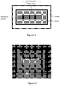
Figure 4 : Typical cross section of a refractory after a corrosion test. The sample (white rectangle in the centre) is surrounded by solidified corrosive slag (vitreous layer) and the hearth (outer portion). -
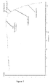
Figure 5 : Penetration of potassium, a corrosive agent, in a refractory with a different chemical composition. -
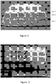
Figure 6 :3 refractory test specimens with a composition gradient as in example 1 (MR1) after a thermal shock test. -
Figure 7 : Trend in refractoriness under load of the composite with a composition gradient MR1. L0 indicates the length of the refractory material in the cylinder at the temperature of 0°C; dL indicates the variation in the length of the refractory material in the cylinder; dLmax indicates the maximum variation in the length of the refractory material in the cylinder; T= temperature. - The proposed solution consists in the use of refractory materials, wherein the compositional variation is achieved starting from two types of refractory material:
- A higher quality material (free of silica, rich in alumina and with a variable percentage of calcium oxide (CaO) and/or magnesia (MgO)), used for the layer facing towards the combustion environment (fire side), so as to lend properties of corrosion resistance to the surface;
- A more economical and conventional material (e.g.: mullite, andalusite) resistant to thermal shock, used in the thick part of the refractory at the back (bulk side) and whose function is to thermally insulate and withstand thermal shocks;
- The invention further proposes interposing at least a third layer with an intermediate composition (intermediate layer) so as to decrease/eliminate possible stresses generated by the different thermal expansions and facilitate adhesion between the two outer layers.
-
Figure 1 shows a perspective view of the cross section of a typical refractory composite made according to the criteria of the proposed invention. The three layers with a different chemical composition are indicated in the figure: Fire side (A), Intermediate layer (B), and Bulk side (C). This is the basic configuration of the refractory composite. In order to improve adhesion and minimize stresses due to the different thermal behaviour of the outer layers (fire side and bulk side), it is possible to make a refractory composite with a composition gradient having an improved configuration characterized by the interposition of a number of transition layers with a different intermediate composition: B1, B2, B3 etc. - In the figure it may further be noted that the refractory composite can be made with flared lateral walls so as to be better adapted for lining the interior of a combustion chamber, the shape of which is commonly cylindrical.
- Chemical compositions proposed for the three layers of the refractory composite are indicated in Table 1.
Table 1 chemical composition of the three layers of the refractory composite Layer Position Function Chemical composition A Fire side Corrosion resistance Al2O3+MgO+CaO B Intermediate layer Adhesion + minimizing stresses Al2O3+MgO+SiO2+CaO C Bulk side Thermal shock resistance Al2O3+ SiO2+CaO - Layer A, or the "fire side", consists of a refractory with a particle size smaller than or equal to 6 mm, the aim being to create a surface with low porosity and thus less subject to the physical penetration of corrosive agents. The chemical composition of the fire side of the refractory may vary within the intervals indicated in the table below.
Table 2: minimum and maximum contents of the compounds making up the chemical composition of layer A, or the "fire side", expressed as a percentage (%) by weight of the final material. Fire side (A) Minimum Content Maximum Content Chemical compound % by weight % by weight Al2O3 80 99 MgO 0 10 CaO 1 10 - For the purpose of preparing the cementitious mixture, distilled water is added in an amount ranging from 3 to 15% of the total weight of the refractory, an amount that is lost during the heat treatment.
- The thickness of the fire side layer in the refractory composite preferably varies from 2 to 10 mm.
- In a preferred embodiment, magnesia is present as magnesium aluminate (MgAl2O) in the crystallographic form of spinel.
- In a further embodiment, in order to obtain a fire side layer particularly resistant to alkali corrosion, part of the calcium oxide and alumina is present in the crystallographic form of calcium hexa-aluminate (Ca(Al2O3)6).
- The mixture of the intermediate layer, or layer B, consists of particles having a size smaller than or equal to 10 mm. In the basic configuration, the chemical composition of layer B is a mixture with 50% by volume of the refractory material used for the fire side and the remaining 50% consisting of the refractory material of the bulk layer.
The chemical composition of the intermediate layer may vary within the following intervals:Table 3: minimum and maximum contents of the compounds making up the chemical composition of the intermediate layer or layer B, expressed as a percentage (%) by weight of the final material. Intermediate layer (B) 50:50 (% by volume of the material of layer A: % by volume of the material of layer C) Minimum Content Maximum Content Chemical compound % by weight % by weight Al2O3 68 95.4 SiO2 3.8 18 MgO 0 6 CaO 0.8 8 - In order to facilitate the homogenization of the various constituents, it is proposed to add a dispersing agent to the mix B. A dispersing agent is an organic additive and, like all organic additives, it does not appear in the percentage calculation of the chemical compounds of the refractory. It is added to the refractory mix in an amount ranging from 0 to 3% relative to the total weight of the refractory component. The preferred dispersing agents are synthetic polyelectrolytes such as ammonium polyacrylate or else alumina-based dispersants (such as the ADS and ADW types).
- For the purpose of preparing the cementitious mixture, distilled water is added in an amount ranging from 3 to 15% of the total refractory content and which is lost during the heat treatment.
- The intermediate layer B of the refractory composite preferably has a thickness varying from 2 to 10 mm.
- In the improved configuration, more than one intermediate layer B can be made (B1, B2, B3 etc.), with percentages by volume of the fire side and bulk side materials which may be varied so as to form the composition gradient along the cross section of the refractory.
- The refractory material making up the bulk layer, or layer C, of the refractory consists of a refractory cement with a particle size smaller than or equal to 10 mm and has a chemical composition which may vary within the following intervals:
Table 4: minimum and maximum contents of the compounds making up the chemical composition of the bulk layer or layer C, expressed as a percentage (%) by weight of the final material. Bulk layer (C) Minimum Content Maximum Content Chemical compound % by weight % by weight Al2O3 50 90 SiO2 9.5 45 CaO 0.5 5.0 - For the purpose of preparing the cementitious mixture, distilled water is added in an amount ranging from 3 to 15% of the total refractory content and which is lost during the heat treatment.
- Layer C of the refractory composite preferably has a thickness of 10 to 80 mm.
- In order to produce a refractory composite with a composition gradient intended for characterization, the various mixes can be cast sequentially in to a mould to form the different layers and the material processed according to standard UNI EN ISO 1927-5:2013.
- The refractory composite can be applied in the combustion chamber of an industrial plant in two different ways:
- 1. by spraying, with a spray gun, the three or more successive layers of the refractory mixes with a different chemical composition;
- 2. by installing a lining made up of refractory composites with a composition gradient previously pre-made by forming in moulds.
- With the aid of the accompanying figures and examples, a description of particular embodiments will now be provided with the aim of offering a better understanding of the objects, features, advantages and modes of application of the invention. It will be noted that the present invention is not limited only to the examples set forth below.
- The refractory composite of example 1 was produced by casting in sequence three refractory cements having a different chemical composition, according to the basic configuration (layers A, B and C). For this purpose, use was made of a wood mould having dimensions of 170x100x65mm.
- In order to obtain a bulk layer, or layer C, about 50 mm thick, an amount of 2004g of refractory cement was weighed out; the cement had a particle-size class of 6 mm and the following chemical composition:
Table 5 chemical composition of the bulk layer, or layer C, of the refractory Bulk layer (C) Content Percentage by weight Chemical compound [g] [%] Al2O3 1173.9 58.6 CaO 47.4 2.4 SiO2 782.6 39.0 Total 2003.9 100.0 - This is a typical alumino silicate-based refractory conventionally used to line combustion chambers. The refractory powder was mixed by means of a mixer and 112g of distilled water was added slowly in order to obtain a mixture with sufficient fluidity for casting. The mixture was poured into the mould so as to form the so-called bulk layer or layer C. In order to distribute the refractory material evenly in the mould, the system was made to vibrate for 60 seconds on a special platform, with the vibration amplitude being set at 0.50mm and the frequency at 50Hz. Then the upper surface of the cast refractory was scratched to facilitate adhesion of the next refractory layer. The bulk layer thus formed will hereinafter be identified with the label SAC.
- In order to make an intermediate layer, or layer B, about 5mm thick, an amount of 50% by volume of the fire side refractory cement was mixed with an equivalent amount (50% by volume) of the bulk side refractory cement so as to obtain a mixture with the following chemical composition:
Table 6 chemical composition of the intermediate layer or layer B Intermediate layer (B) 50:50 (% by volume of the material of layer A: % by volume of the material of layer C) Content Percentage by weight Chemical compound [g] [%] Al2O3 195.2 77.2 MgO 14.2 5.6 CaO 4.4 1.7 SiO2 39.1 15.5 Total 252.9 100.0 - The maximum particle size of the powders used is 6 mm. An alumina-based dispersing agent was added to the above-described refractory mixture (Table 6) in an amount of 1% by weight, relative to the total weight of the refractory component. The powders were mixed with a mixer while an amount of distilled water equal to 11.6g was added dropwise. A homogeneous mixture was obtained, with a fluidity suitable for casting in the mould above layer C. The mixture was then distributed inside the mould so as to form a layer of homogeneous thickness. The upper surface of layer B was scratched to favour adhesion with the last layer, or layer A, of refractory cement.
- In order to form a corrosion resistant layer (fire side) about 10 mm thick, an amount of 610.9 g of refractory cement with the following chemical composition was weighed out and mixed:
Table 7 chemical composition of the corrosion resistant layer or fire side Fire side (A) Content Percentage by weight Chemical compound [g] [%] Al2O3 545.9 89.4 MgO 56.7 9.3 CaO 8.3 1.3 Total 610.9 100.0 - Magnesia is present in this mix only as magnesium aluminate (MgAl2O) in the crystallographic form of spinel, whose dilatometric behaviour makes it much more similar to alumina, the main constituent of the fire side, than magnesia. The latter is subject to considerable thermal expansion, which, within a refractory component, can be a cause of breakage during cycling. It follows that the refractory composite containing magnesium aluminate in spinel form is less subject to breakage due to thermal shock than is the case with magnesia.
- To facilitate mixing, an alumina-based dispersing agent was added to the above-described mixture in an amount of 1% by weight, relative to the total weight of the refractory component (Table 7).
- The maximum particle size of the mixture was 2 mm.
- During mixing, 28.1g of distilled water was added slowly in order to obtain a homogeneous mixture with sufficient fluidity for casting in the mould. The mixture thus obtained was poured over layer B and distributed so as to form a layer of homogeneous thickness (fire side) which we will identify hereinafter with the label MAS.
- The green composite thus produced was prepared, dried and sintered according to the procedure of standard UNI EN ISO 1927-5:2013. A perspective view of the refractory composite thus produced is shown in
Figure 2 . - The refractory composite of example 2 was produced by casting 4 layers of refractory cement in sequence in a mould, the layers having a different chemical composition according to an improved configuration: 2 of the 4 layers (B1 and B2) consisted of an intermediate composition relative to the outer layers (bulk side C and fire side A) in order to improve adhesion and decrease the stresses within the refractory composite. The dimensions of the wood mould used were 170x100x65 mm.
- In order to obtain a bulk layer about 45 mm thick, an amount of 1803g of aluminosilicate-based refractory cement with the following chemical composition was weighed out:
Table 8 chemical composition of the bulk layer of the refractory Bulk layer (C) Content Percentage by weight Chemical compound [g] [%] Al2O3 1056,5 58,6 CaO 42,6 2,4 SiO2 704,3 39,0 Total 1803,4 100,0 - This is an aluminosilicate-based refractory cement conventionally used to line combustion chambers. The material has a particle-size class of 6 mm. The above-described mixture (Table 8) was mixed by means of a mixer and 99g of distilled water was added slowly in order to obtain a mixture with sufficient fluidity for casting. The mixture was poured into the mould so as to form the so-called bulk layer, which we will identify hereinafter with the label SAC. In order to distribute the refractory material evenly in the mould, the system was made to vibrate for 30 seconds on a special platform, with the vibration amplitude being set at 0.50mm and the frequency at 50Hz. Then the upper surface of the cast refractory was scratched to facilitate adhesion of the next layer.
- Two layers (B1 and B2) with an intermediate chemical composition relative to those of the bulk layer and corrosion resistant layer were cast in sequence over the bulk layer.
- In order to obtain the first intermediate layer (B1), about 5mm thick, an amount of 50% by volume of the fire side refractory cement was mixed with an equivalent amount (50% by volume) of the bulk side refractory cement so as to obtain a mixture with the following chemical composition:
Table 9 chemical composition of the intermediate layer with the percentage by volume of the bulk composition and the corrosion resistant composition equal to 50:50 Intermediate layer (B1) 50:50 (% by volume of the material of layer A: % by volume of the material of layer C) Content Percentage by weight Chemical compound [g] [%] Al2O3 202.1 81.3 CaO 7.5 3.0 SiO2 39.1 15.7 Total 248.7 100.0 - The maximum particle size of the powders used was 6 mm.
- In order to facilitate the homogenization of the mix, an alumina-based dispersing agent was added to the above-described refractory mixture (Table 9) in an amount of 1% by weight, relative to the total weight of the refractory component.
- The mixture was mixed by means of a mixer while an amount of distilled water equal to 11.7g was added slowly. A homogeneous mixture was obtained, with a fluidity suitable for casting in the mould above the bulk layer. The mix was distributed in such a way as to form a layer of constant thickness. The upper surface of the layer was scratched to favour adhesion of the third layer of refractory cement.
- In order to obtain a further intermediate layer (B2), about 5mm thick, an amount of 75% by volume of the fire side refractory cement was mixed with an amount of 25% by volume of the bulk side refractory cement so as to obtain a mixture with the following chemical composition:
Table 10 Chemical composition of the intermediate layer with a percentage by volume of the corrosion resistant layer relative to the bulk layer equal to 75:25 Intermediate layer (B2) 75:25 (% by volume of the material of layer A: % by volume of the material of layer C) Content Percentage by weight Chemical compound [g] [%] Al2O3 244 89.6 CaO 8.8 3.2 SiO2 20 7.2 Total 272.8 100.0 - The maximum particle size of the powders used was 6 mm.
- An alumina-based dispersing agent was also added to the above-described refractory mixture (Table 10) in an amount of 1% by weight, relative to the total weight of the refractory component.
- All the ingredients were then mixed with a mixer, with an amount of water equal to 13.1g being added dropwise in order to fluidize the mixture and make it castable. The mixture was then poured into the mould and distributed so as to form a layer of homogeneous thickness.
- In order to obtain a corrosion resistant layer (fire side) about 10 mm thick, an amount of 594g of refractory cement with the following chemical composition was weighed out:
Table 11: chemical composition of the corrosion resistant layer or fire side layer Fire side (A) Content Percentage by weight Chemical compound [g] [%] Al2O3 573,5 96,6 CaO 20,5 3,4 Total 594,0 100,0 - It will be noted that in order to obtain a fire side layer particularly resistant to alkali corrosion, use was made of part of a refractory mixture in which part of the calcium oxide and alumina is present in the crystallographic form of calcium hexa-aluminate (Ca(Al2O3)6), whose properties of resistance to alkali corrosion are well known.
- With the aim of facilitating the homogenization of the compounds, an alumina-based dispersing agent was added to the above-described mixture (Table 11) in an amount of 1.5% relative to the total weight of the refractory component.
- The maximum particle size of the powders used was 2 mm.
- During mixing, 27.9g of distilled water was added slowly in order to obtain a homogeneous mixture with sufficient fluidity for being cast in the mould to form the corrosion resistant layer. The mixture was then levelled so as to obtain a layer of homogeneous thickness, which we will identify hereinafter with the label CA6 (fire side A).
- The green composite thus produced was prepared, dried and sintered according to the procedure of standard UNI EN ISO 1927-5:2013.
- In order to verify the corrosion resistance of the refractory composites thus produced, tests were carried out according to the static scheme shown in
Figure 3 . These are tests for which no specific standards are available. - The sample subjected to testing consisted solely of the fire side layer of the refractory composite, which, during the process is directly exposed to the aggressive atmosphere of the combustion chamber.
- During the test, a representative fraction of the fire side layer was immersed in a corrosive mixture (slag) consisting of SiO2/K2O with a ratio of 2.5 by weight. The slag composition was chosen because it is representative of the species which enter into contact with the refractory during co-combustion processes. It will be noted that the agents that are corrosive for the refractory under these conditions are essentially alkaline species. In this specific test, potassium tends to penetrate into the refractory, forming low melting point phases with the silica or, alternatively, in the presence of alumina, crystalline phases with an expansion in volume. Both situations damage the refractory. For this reason, the objective of the test is to verify the concentration of potassium at a different distance from the surface of the refractory after the test. The test is conducted by maintaining the slag/refractory system at a temperature of 950°C, representative of the co-combustion process, for 72 hours.
- The samples subjected to testing were obtained both from the refractory composite of example 1, MAS (fire side or layer A of the refractory material MR1 of example 1), and from the refractory composite of example 2, CA6 (fire side or layer A of the refractory material BON of example 2). For the sake of comparison, the aluminosilicate-based material making up the bulk layer of the two examples (SAC) was also tested because it is representative of the materials conventionally used in combustion chambers (
Figure 4 ). - At the end of each test the tested samples were investigated by scanning electron microscopy (SEM). The concentration of potassium (corrosive agent) at a different distance from the edge was measured by energy dispersive spectroscopy (EDX) in order to verify the penetration. The results of the analysis have been compared in the graph in
Figure 5 . - From the graph one notes that the penetration of the corrosive agent is distinctly lower ([K2O] ≤1.5%) in the case of the new materials (CA6 and MAS), which make up the fire side of the refractory, than in the material (SAC) (7%>[K2O] >1%), conventionally used in combustion chambers. Based on these results, it may be concluded that the presence of the facing layer, or fire side, both in the composition based on magnesium aluminate in the spinel form (MAS) and in the composition based on calcium hexa-aluminate (CA6), assures excellent properties of corrosion resistance in the refractory compared to conventional refractories.
- The determination of the thermal conductivity of the layers of the refractory is necessary to enable a correct dimensioning of the refractory based on the degree of thermal insulation that must be reached in the combustion chamber.
- The thermal diffusivity (α) and the specific heat (Cp) of the outer layers of the refractory were measured according to standard ASTM E-1461. The results are shown in Table 12 and Table 13.
Table 12: specific heat of the materials making up the outer layers of the refractory in the two examples (MAS and CA6); the data for the material conventionally used in combustion chambers (SAC) are included as a reference Specific heat Cp Fire side (A) of example 1: MAS Fire side (A) of example 2: CA6 Bulk layer (C) of examples 1 and 2: SAC Temperature [°C] [J/(g·K)] [J/(g·K)] [J/(g·K)] 500 0.96±0.08 1.09±0.05 1.03±0.02 1000 1.72±0.19 1.74±0.20 1.65±0.17 Table 13: thermal diffusivity of the materials making up the outer layers of the refractory in the two examples (MAS and CA6); the data for the material conventionally used in combustion chambers (SAC) are included as a reference Thermal diffusivity α Fire side (A) of example 1: MAS Fire side (A) of example 2: CA6 Bulk layer (C) of examples 1 and 2: SAC Temperature [°C] [mm2/s] [mm2/s] [mm2/s] 500 0.92±0.02 0.72±0.01 0.59±0.01 1000 0.86±0.04 0.74±0.03 0.61±0.01 - The thermal conductivity (K) was derived by applying the following formula:

Table 14: Thermal conductivity of the materials making up the outer layers of the refractory in the two examples (MAS and CA6); the data for the material conventionally used in combustion chambers (SAC) are included as a reference Thermal conductivity K Fire side (A) of example 1: MAS Fire side (A) of example 2: CA6 Bulk layer (C) of examples 1 and 2: SAC Temperature [°C] [W/(m·K)] [W/(m·K)] [W/(m·K)] 500 2.24±0.05 1.60±0.08 1.43±0.05 1000 3.72±0.38 2.58±0.28 2.33±0.35 - Depending on the thermal insulation requirements for the specific applications, the thicknesses of the layers A, B and C of the refractory must be varied on the basis of these experimental results.
- Cylindrical test specimens with a diameter of 35 mm and height of 50 mm were obtained from the refractory in order to assess the thermal shock resistance thereof according to standard DIN51068. According to this standard, the test specimens are subjected to thermal cycling comprising the following steps:
- 1. drying at 110±5 °C for 30 minutes;
- 2. introduction into a furnace set at a temperature of 950°C with at least a 15-minute dwell after the set temperature has been reached;
- 3. extraction from the furnace and rapid cooling by immersion in cold water.
- The test is considered to have been passed if the specimen withstands 30 thermal cycles.
- Three test specimens were obtained from each of the refractory composites of the two examples to verify the repeatability of the thermal shock test on a minimum statistical basis. Test results are shown in Table 15.
Table 15: Result of thermal shock resistance test on the composites Specimen no. Example 1 (MR1) Example 2 (BON) 1 Positive Positive 2 Positive Positive 3 Negative (breakage at 10th cycle) Negative (breakage at 13th cycle) - For both examples (MR1 and BON) it may be noted that (
Figure 6 ): - two out of three specimens passed the thermal shock test;
- the third test specimen broke, with a fracture at the interface between layers, ascribable to the different thermal behaviour of the layers with a different chemical composition;
- in all cases the refractory material making up the bulk layer of the refractory (SAC) was not damaged by the test.
- These results demonstrate that
- 1. the material conventionally used to line combustion chambers (SAC) possesses excellent properties of thermal shock resistance;
- 2. the refractories are more subject to thermal shock than the conventional refractories (SAC) because of the joining together of layers with a different dilatometric behaviour.
- However, it is well known that dense comprising alumina or silicon carbide materials, considered an alternative that improves the property of corrosion resistance compared to conventional refractories, are easily subject to breakage due to thermal shocks. Therefore, the refractories of the present invention represent an improved alternative in terms of resistance to thermal cycling.
- This is a measurement serving to establish the maximum temperature at which refractories can be used.
- The refractoriness under load of the refractory composites of the two examples was measured according to standard EN 993-8. It is a specific measurement of the behaviour of a refractory material subjected to the combined effects of a constant load (0.2MPa) and a constant increase in temperature over time (5K/min). A measurement is made of the curve of deformation of the test specimen in height as a function of temperature.
- For the purpose of carrying out the test, standard cylindrical test specimens were obtained (d=50mm and h=50mm), with the axis of the cylinder oriented in a direction parallel to the composition gradient.
- An example of a deformation measured on sample MR1 is shown in the graph in
Figure 7 . - The results of the two tests are shown in Table 16.
Table 16 Results of the test of refractoriness under load conducted on the refractory composites of example 1 (MR1) and example 2 (BON) Refractoriness under load Example 1 (MR1) Example 2 (BON) dLmax 0.842% 0.798% T(dLmax) 1,243.8°C 1,261.1°C T (0.5%) 1,405.9°C 1,412.8°C T(1.0%) 1,454.3°C 1,474.0°C T(2.0%) 1,505.5°C 1,527.9°C T(5,0%) 1,615.6°C - - The results demonstrate that the refractories with a of example 1 (MR1) and example 2 (BON) expand notwithstanding the applied load up to a temperature (TdLmax) of 1,243.8°C and 1,261.1°C, respectively. Above these temperatures, phenomena of shrinkage begin to occur, which could limit their use.
- Since the temperature of the combustion process (950°C) for producing energy or for waste disposal is lower than the T(dLmax) of both examples, it can be affirmed with absolute confidence that the two refractories (MR1 and BON) can be used to line the interior of combustion chambers.
- The proposed solution displays a higher resistance to the corrosion due to the action of alkalis compared to the materials conventionally used (aluminosilicates).
- When used as an alternative to the conventional refractory, the proposed solution moreover displays a better performance in thermal cycling than high density materials (alumina and SiC).
- Finally, the proposed solution makes any higher costs of installing the multilayer refractory acceptable given the better performance of the material in terms of corrosion and thermal shock resistance, which makes it possible to reduce maintenance costs, with a net gain resulting from the reduction of downtimes between plant shutdowns and restarts.
Claims (10)
- A refractory material characterized by more than one layer with different chemical compositions, comprising at least:a) a layer A (fire side) of refractory material free of silica (SiO2) comprising by weight:80 to 99% alumina (Al2O3),1 to 10% calcium oxide (CaO),0 to 10% magnesia (MgO),b) a layer C (bulk side) of refractory material comprising by weight:9.5 to 45% silica (Si02),50 to 90 % alumina (Al2O3),0.5 to 5% calcium oxide (CaO),c) at least one layer B (intermediate layer) of refractory material, interposed between layer A and layer C, comprising a mixture of the material of layer A and the material of layer C, comprising:68 to 95.4 % by weight of alumina (Al2O3),3.8 to 18% by weight of silica (Si02),0.8 to 8% by weight of calcium oxide (CaO),0 to 6% by weight of magnesia (MgO).
- The refractory material according to claim 1, wherein the refractory material of layer A has a particle size smaller than or equal to 6mm, and the refractory material of layers B and C has a particle size smaller than or equal to 10mm.
- The refractory material according to any one of the preceding claims, wherein layers A and B have a thickness of 2 to 10mm and layer C has a thickness of 10 to 80mm.
- The refractory material according to any one of the preceding claims, wherein the refractory material of layer B consists in a % by volume of the material of layer A varying from 50% to 75% and a % by volume of the material of layer C varying from 25% to 50%.
- The refractory material according to the preceding claims, comprising a number of layers B, each consisting of a refractory material as defined in claim 4, said material having a percentage by volume of the material of layer A which increases as a function of the distance of said layer B from layer C.
- A product consisting of the refractory material according to any one of the preceding claims, made by forming in moulds.
- Use of the refractory material as defined in any one of claims 1 to 5 or of the product according to claim 6, as a lining of a combustion chamber, preferably with fuel consisting of biomass, wherein layer A of said material is facing towards the combustion room (fire side) and layer C is in the part at the back (bulk side).
- Process for preparing the refractory material as defined in any one of the claims 1 to 5, comprising the steps of:a) mixing the components of the material of layer C, adding distilled water dropwise until obtaining a homogeneous and fluid mixture;b) casting the mixture obtained in step a) in a mould so as to form a layer of homogeneous thickness;c) scratching the surface of layer C;d) mixing the components of the material of a first layer B1, adding distilled water dropwise until obtaining a homogeneous and fluid mixture;e) casting the mixture obtained in step d) over layer C and distributing it so as to form a layer of homogeneous thickness;f) scratching the surface of layer B1;g) optionally mixing the components of the material of a second layer B2, adding distilled water dropwise until obtaining a homogeneous and fluid mixture;h) casting the mixture obtained in step g) over the preceding layer B and distributing it so as to form a layer of homogeneous thickness;i) scratching the surface of layer B2;l) optionally repeating steps g)-i) one or more times using the components of the material of a third layer B3, of a fourth layer B4 etc.;m) mixing the components of the material of layer A, adding distilled water dropwise until obtaining a homogeneous and fluid mixture;n) casting the mixture obtained in step m) over the last layer B and distributing it so as to form a layer of homogeneous thickness;o) drying.
- Process of applying the refractory material as defined in any one of the claims 1 to 5 to the walls of a combustion chamber, comprising a step of spraying, with a spray gun, refractory mixes/mixtures with a different composition as defined in claim 1, according to the following sequence: spraying of the mixtures: layer C, at least one layer B, optionally one or more further layers B, and layer A.
- Process of applying the refractory material as defined in any one of the claims 1 to 5 to the walls of a combustion chamber, comprising a step of laying a lining consisting of the product as defined in claim 6.
Applications Claiming Priority (1)
| Application Number | Priority Date | Filing Date | Title |
|---|---|---|---|
| PCT/IB2015/054421 WO2016198917A1 (en) | 2015-06-11 | 2015-06-11 | Refractories for applications in combustion chambers intended for producing energy and/or waste disposal |
Publications (2)
| Publication Number | Publication Date |
|---|---|
| EP3307695A1 EP3307695A1 (en) | 2018-04-18 |
| EP3307695B1 true EP3307695B1 (en) | 2019-03-13 |
Family
ID=53762226
Family Applications (1)
| Application Number | Title | Priority Date | Filing Date |
|---|---|---|---|
| EP15744663.4A Active EP3307695B1 (en) | 2015-06-11 | 2015-06-11 | Refractories for applications in combustion chambers intended for producing energy and/or waste disposal |
Country Status (4)
| Country | Link |
|---|---|
| US (1) | US10611691B2 (en) |
| EP (1) | EP3307695B1 (en) |
| ES (1) | ES2730400T3 (en) |
| WO (1) | WO2016198917A1 (en) |
Families Citing this family (3)
| Publication number | Priority date | Publication date | Assignee | Title |
|---|---|---|---|---|
| CN107726856A (en) * | 2017-11-23 | 2018-02-23 | 苏州哈雅西节能科技有限公司 | A kind of high temperature resistant furnace wall compound lining with high-heating radiation with strong disconnected hot property |
| CN110282991B (en) * | 2019-08-13 | 2022-05-17 | 瑞泰马钢新材料科技有限公司 | Tundish magnesium coating prepared by using waste magnesium aluminate spinel as raw material and method |
| CN117682877B (en) * | 2023-11-27 | 2024-10-18 | 江苏诺明高温材料股份有限公司 | Preparation method of chromium-free corrosion-resistant refractory composite material for RH refining furnace |
Family Cites Families (6)
| Publication number | Priority date | Publication date | Assignee | Title |
|---|---|---|---|---|
| US2838882A (en) * | 1952-01-29 | 1958-06-17 | Silverman Alexander | Method of producing glass |
| CS199377B1 (en) * | 1977-05-13 | 1980-07-31 | Valter Boehm | Connecting method of at least two ceramic materials |
| DE10302519B3 (en) | 2003-01-23 | 2004-07-08 | Robert Bosch Gmbh | Ceramic layer system for gas sensor elements, has two oxide ceramic layers separated by electrically insulating intermediate layer |
| US20090293786A1 (en) * | 2008-05-27 | 2009-12-03 | Olver John W | Biomass Combustion Chamber and Refractory Components |
| CN203728861U (en) | 2013-10-29 | 2014-07-23 | 宝山钢铁股份有限公司 | Brick distribution structure with thermal conductivity gradient of hearth refractory |
| CN203928734U (en) | 2014-03-03 | 2014-11-05 | 峨眉山市峨冶耐火材料厂 | A kind of recuperative heater furnace top insulation structure |
-
2015
- 2015-06-11 ES ES15744663T patent/ES2730400T3/en active Active
- 2015-06-11 WO PCT/IB2015/054421 patent/WO2016198917A1/en not_active Ceased
- 2015-06-11 US US15/580,943 patent/US10611691B2/en active Active
- 2015-06-11 EP EP15744663.4A patent/EP3307695B1/en active Active
Non-Patent Citations (1)
| Title |
|---|
| None * |
Also Published As
| Publication number | Publication date |
|---|---|
| ES2730400T3 (en) | 2019-11-11 |
| EP3307695A1 (en) | 2018-04-18 |
| WO2016198917A1 (en) | 2016-12-15 |
| US20180162778A1 (en) | 2018-06-14 |
| US10611691B2 (en) | 2020-04-07 |
Similar Documents
| Publication | Publication Date | Title |
|---|---|---|
| JP4376579B2 (en) | Silicon nitride bonded SiC refractory and method for producing the same | |
| EP2250141B2 (en) | Use of a sintered refractory material based on silicon carbide with a silicon nitride binder | |
| US8901022B2 (en) | Powder for dry refractory material | |
| EP3397411B1 (en) | Castable refractory compositions comprising zeolithic microstructures and uses thereof | |
| RU2417966C2 (en) | Burnt refractory ceramic product | |
| Xu et al. | Comparison of microstructure, thermo-mechanical property and corrosion resistance of bauxite-corundum refractory castables reinforced by two approaches | |
| KR20150067225A (en) | Chromium oxide product | |
| Gu et al. | Interfacial spinellisation of MgO–C/Al2O3–C composite functional refractory component at high temperatures | |
| US10611691B2 (en) | Refractories for applications in combustion chambers intended for producing energy and/or waste disposal | |
| BRPI0821583B1 (en) | SINTERED REFRACTORY PRODUCT, REFRACTORY BLOCK, DEVICE CHOSEN BETWEEN AN OVEN AND A HEAT EXCHANGER, AND, PROCESS OF MANUFACTURE OF A REFRACTORY BLOCK | |
| Kumar et al. | Use of alumina dispersant in alumina‐spinel castable: Comparison between in situ and preformed spinels | |
| Silva et al. | Effect of alumina and silica on the hydration behavior of magnesia‐based refractory castables | |
| CN101500964B (en) | Baked refractory product | |
| US20140030163A1 (en) | Product of chromium oxide, zirconium oxide and hafnium oxide | |
| Ewais et al. | Effect of hercynite spinel on the technological properties of MCZ products used for lining cement rotary kilns | |
| Mgbemere et al. | The Effects of Sintering Temperature and Agro Wastes on the Properties of Insulation Bricks | |
| Ibitoye et al. | Adaptation of Odolewu clay for use as refractory material | |
| JP7119870B2 (en) | Evaluating Method of Delamination Resistance of Alumina-Magnesia Castable Refractories | |
| RU2443657C1 (en) | Charge to manufacture periclase-spinel products | |
| Al Hwaidy et al. | Study the effect of using local materials as refractory bonding mortar in iraqi | |
| JP2013067548A (en) | Monolithic refractory | |
| JP4751277B2 (en) | Non-adhesive continuous casting nozzle | |
| Qin et al. | Binder Effect on Corrosion Mechanism of Al2 O3‒Cr2 O3 Castables for Copper Anode Fire Refining | |
| JP4704263B2 (en) | Amorphous refractory molding material and Amorphous refractory molding | |
| Wenzel et al. | Development of Porous Ceramic Preforms Based on Magnesia Partially Stabilised Zirconia with Additions of MgAl2O4, MgO, Al2O3 and Ti |
Legal Events
| Date | Code | Title | Description |
|---|---|---|---|
| STAA | Information on the status of an ep patent application or granted ep patent |
Free format text: STATUS: THE INTERNATIONAL PUBLICATION HAS BEEN MADE |
|
| PUAI | Public reference made under article 153(3) epc to a published international application that has entered the european phase |
Free format text: ORIGINAL CODE: 0009012 |
|
| STAA | Information on the status of an ep patent application or granted ep patent |
Free format text: STATUS: REQUEST FOR EXAMINATION WAS MADE |
|
| 17P | Request for examination filed |
Effective date: 20180108 |
|
| AK | Designated contracting states |
Kind code of ref document: A1 Designated state(s): AL AT BE BG CH CY CZ DE DK EE ES FI FR GB GR HR HU IE IS IT LI LT LU LV MC MK MT NL NO PL PT RO RS SE SI SK SM TR |
|
| AX | Request for extension of the european patent |
Extension state: BA ME |
|
| REG | Reference to a national code |
Ref country code: DE Ref legal event code: R079 Ref document number: 602015026383 Country of ref document: DE Free format text: PREVIOUS MAIN CLASS: C04B0035101000 Ipc: C04B0041000000 |
|
| DAV | Request for validation of the european patent (deleted) | ||
| DAX | Request for extension of the european patent (deleted) | ||
| GRAP | Despatch of communication of intention to grant a patent |
Free format text: ORIGINAL CODE: EPIDOSNIGR1 |
|
| STAA | Information on the status of an ep patent application or granted ep patent |
Free format text: STATUS: GRANT OF PATENT IS INTENDED |
|
| RIC1 | Information provided on ipc code assigned before grant |
Ipc: C04B 35/634 20060101ALI20180914BHEP Ipc: C04B 35/66 20060101ALI20180914BHEP Ipc: C04B 35/101 20060101ALI20180914BHEP Ipc: C04B 41/00 20060101AFI20180914BHEP Ipc: C04B 41/50 20060101ALI20180914BHEP Ipc: C04B 35/626 20060101ALI20180914BHEP Ipc: C04B 35/63 20060101ALI20180914BHEP Ipc: C04B 35/443 20060101ALI20180914BHEP Ipc: F27D 1/00 20060101ALI20180914BHEP Ipc: C04B 41/87 20060101ALI20180914BHEP Ipc: B32B 18/00 20060101ALI20180914BHEP Ipc: C04B 35/64 20060101ALI20180914BHEP |
|
| INTG | Intention to grant announced |
Effective date: 20181002 |
|
| GRAS | Grant fee paid |
Free format text: ORIGINAL CODE: EPIDOSNIGR3 |
|
| GRAA | (expected) grant |
Free format text: ORIGINAL CODE: 0009210 |
|
| STAA | Information on the status of an ep patent application or granted ep patent |
Free format text: STATUS: THE PATENT HAS BEEN GRANTED |
|
| AK | Designated contracting states |
Kind code of ref document: B1 Designated state(s): AL AT BE BG CH CY CZ DE DK EE ES FI FR GB GR HR HU IE IS IT LI LT LU LV MC MK MT NL NO PL PT RO RS SE SI SK SM TR |
|
| REG | Reference to a national code |
Ref country code: GB Ref legal event code: FG4D |
|
| REG | Reference to a national code |
Ref country code: CH Ref legal event code: EP Ref country code: AT Ref legal event code: REF Ref document number: 1107471 Country of ref document: AT Kind code of ref document: T Effective date: 20190315 |
|
| REG | Reference to a national code |
Ref country code: DE Ref legal event code: R096 Ref document number: 602015026383 Country of ref document: DE |
|
| REG | Reference to a national code |
Ref country code: IE Ref legal event code: FG4D |
|
| REG | Reference to a national code |
Ref country code: NL Ref legal event code: MP Effective date: 20190313 |
|
| REG | Reference to a national code |
Ref country code: LT Ref legal event code: MG4D |
|
| PG25 | Lapsed in a contracting state [announced via postgrant information from national office to epo] |
Ref country code: SE Free format text: LAPSE BECAUSE OF FAILURE TO SUBMIT A TRANSLATION OF THE DESCRIPTION OR TO PAY THE FEE WITHIN THE PRESCRIBED TIME-LIMIT Effective date: 20190313 Ref country code: NO Free format text: LAPSE BECAUSE OF FAILURE TO SUBMIT A TRANSLATION OF THE DESCRIPTION OR TO PAY THE FEE WITHIN THE PRESCRIBED TIME-LIMIT Effective date: 20190613 Ref country code: LT Free format text: LAPSE BECAUSE OF FAILURE TO SUBMIT A TRANSLATION OF THE DESCRIPTION OR TO PAY THE FEE WITHIN THE PRESCRIBED TIME-LIMIT Effective date: 20190313 Ref country code: FI Free format text: LAPSE BECAUSE OF FAILURE TO SUBMIT A TRANSLATION OF THE DESCRIPTION OR TO PAY THE FEE WITHIN THE PRESCRIBED TIME-LIMIT Effective date: 20190313 |
|
| PG25 | Lapsed in a contracting state [announced via postgrant information from national office to epo] |
Ref country code: BG Free format text: LAPSE BECAUSE OF FAILURE TO SUBMIT A TRANSLATION OF THE DESCRIPTION OR TO PAY THE FEE WITHIN THE PRESCRIBED TIME-LIMIT Effective date: 20190613 Ref country code: LV Free format text: LAPSE BECAUSE OF FAILURE TO SUBMIT A TRANSLATION OF THE DESCRIPTION OR TO PAY THE FEE WITHIN THE PRESCRIBED TIME-LIMIT Effective date: 20190313 Ref country code: NL Free format text: LAPSE BECAUSE OF FAILURE TO SUBMIT A TRANSLATION OF THE DESCRIPTION OR TO PAY THE FEE WITHIN THE PRESCRIBED TIME-LIMIT Effective date: 20190313 Ref country code: RS Free format text: LAPSE BECAUSE OF FAILURE TO SUBMIT A TRANSLATION OF THE DESCRIPTION OR TO PAY THE FEE WITHIN THE PRESCRIBED TIME-LIMIT Effective date: 20190313 Ref country code: GR Free format text: LAPSE BECAUSE OF FAILURE TO SUBMIT A TRANSLATION OF THE DESCRIPTION OR TO PAY THE FEE WITHIN THE PRESCRIBED TIME-LIMIT Effective date: 20190614 Ref country code: HR Free format text: LAPSE BECAUSE OF FAILURE TO SUBMIT A TRANSLATION OF THE DESCRIPTION OR TO PAY THE FEE WITHIN THE PRESCRIBED TIME-LIMIT Effective date: 20190313 |
|
| REG | Reference to a national code |
Ref country code: AT Ref legal event code: MK05 Ref document number: 1107471 Country of ref document: AT Kind code of ref document: T Effective date: 20190313 |
|
| PG25 | Lapsed in a contracting state [announced via postgrant information from national office to epo] |
Ref country code: CZ Free format text: LAPSE BECAUSE OF FAILURE TO SUBMIT A TRANSLATION OF THE DESCRIPTION OR TO PAY THE FEE WITHIN THE PRESCRIBED TIME-LIMIT Effective date: 20190313 Ref country code: RO Free format text: LAPSE BECAUSE OF FAILURE TO SUBMIT A TRANSLATION OF THE DESCRIPTION OR TO PAY THE FEE WITHIN THE PRESCRIBED TIME-LIMIT Effective date: 20190313 Ref country code: SK Free format text: LAPSE BECAUSE OF FAILURE TO SUBMIT A TRANSLATION OF THE DESCRIPTION OR TO PAY THE FEE WITHIN THE PRESCRIBED TIME-LIMIT Effective date: 20190313 Ref country code: AL Free format text: LAPSE BECAUSE OF FAILURE TO SUBMIT A TRANSLATION OF THE DESCRIPTION OR TO PAY THE FEE WITHIN THE PRESCRIBED TIME-LIMIT Effective date: 20190313 Ref country code: PT Free format text: LAPSE BECAUSE OF FAILURE TO SUBMIT A TRANSLATION OF THE DESCRIPTION OR TO PAY THE FEE WITHIN THE PRESCRIBED TIME-LIMIT Effective date: 20190713 Ref country code: EE Free format text: LAPSE BECAUSE OF FAILURE TO SUBMIT A TRANSLATION OF THE DESCRIPTION OR TO PAY THE FEE WITHIN THE PRESCRIBED TIME-LIMIT Effective date: 20190313 |
|
| REG | Reference to a national code |
Ref country code: ES Ref legal event code: FG2A Ref document number: 2730400 Country of ref document: ES Kind code of ref document: T3 Effective date: 20191111 |
|
| PG25 | Lapsed in a contracting state [announced via postgrant information from national office to epo] |
Ref country code: SM Free format text: LAPSE BECAUSE OF FAILURE TO SUBMIT A TRANSLATION OF THE DESCRIPTION OR TO PAY THE FEE WITHIN THE PRESCRIBED TIME-LIMIT Effective date: 20190313 Ref country code: PL Free format text: LAPSE BECAUSE OF FAILURE TO SUBMIT A TRANSLATION OF THE DESCRIPTION OR TO PAY THE FEE WITHIN THE PRESCRIBED TIME-LIMIT Effective date: 20190313 |
|
| PGFP | Annual fee paid to national office [announced via postgrant information from national office to epo] |
Ref country code: BE Payment date: 20190628 Year of fee payment: 5 |
|
| REG | Reference to a national code |
Ref country code: DE Ref legal event code: R097 Ref document number: 602015026383 Country of ref document: DE |
|
| PG25 | Lapsed in a contracting state [announced via postgrant information from national office to epo] |
Ref country code: IS Free format text: LAPSE BECAUSE OF FAILURE TO SUBMIT A TRANSLATION OF THE DESCRIPTION OR TO PAY THE FEE WITHIN THE PRESCRIBED TIME-LIMIT Effective date: 20190713 Ref country code: AT Free format text: LAPSE BECAUSE OF FAILURE TO SUBMIT A TRANSLATION OF THE DESCRIPTION OR TO PAY THE FEE WITHIN THE PRESCRIBED TIME-LIMIT Effective date: 20190313 |
|
| PLBE | No opposition filed within time limit |
Free format text: ORIGINAL CODE: 0009261 |
|
| STAA | Information on the status of an ep patent application or granted ep patent |
Free format text: STATUS: NO OPPOSITION FILED WITHIN TIME LIMIT |
|
| PG25 | Lapsed in a contracting state [announced via postgrant information from national office to epo] |
Ref country code: DK Free format text: LAPSE BECAUSE OF FAILURE TO SUBMIT A TRANSLATION OF THE DESCRIPTION OR TO PAY THE FEE WITHIN THE PRESCRIBED TIME-LIMIT Effective date: 20190313 Ref country code: MC Free format text: LAPSE BECAUSE OF FAILURE TO SUBMIT A TRANSLATION OF THE DESCRIPTION OR TO PAY THE FEE WITHIN THE PRESCRIBED TIME-LIMIT Effective date: 20190313 |
|
| REG | Reference to a national code |
Ref country code: CH Ref legal event code: PL |
|
| 26N | No opposition filed |
Effective date: 20191216 |
|
| GBPC | Gb: european patent ceased through non-payment of renewal fee |
Effective date: 20190613 |
|
| PG25 | Lapsed in a contracting state [announced via postgrant information from national office to epo] |
Ref country code: SI Free format text: LAPSE BECAUSE OF FAILURE TO SUBMIT A TRANSLATION OF THE DESCRIPTION OR TO PAY THE FEE WITHIN THE PRESCRIBED TIME-LIMIT Effective date: 20190313 |
|
| PG25 | Lapsed in a contracting state [announced via postgrant information from national office to epo] |
Ref country code: GB Free format text: LAPSE BECAUSE OF NON-PAYMENT OF DUE FEES Effective date: 20190613 Ref country code: IE Free format text: LAPSE BECAUSE OF NON-PAYMENT OF DUE FEES Effective date: 20190611 |
|
| PG25 | Lapsed in a contracting state [announced via postgrant information from national office to epo] |
Ref country code: LU Free format text: LAPSE BECAUSE OF NON-PAYMENT OF DUE FEES Effective date: 20190611 Ref country code: LI Free format text: LAPSE BECAUSE OF NON-PAYMENT OF DUE FEES Effective date: 20190630 Ref country code: CH Free format text: LAPSE BECAUSE OF NON-PAYMENT OF DUE FEES Effective date: 20190630 |
|
| REG | Reference to a national code |
Ref country code: BE Ref legal event code: MM Effective date: 20200630 |
|
| PG25 | Lapsed in a contracting state [announced via postgrant information from national office to epo] |
Ref country code: CY Free format text: LAPSE BECAUSE OF FAILURE TO SUBMIT A TRANSLATION OF THE DESCRIPTION OR TO PAY THE FEE WITHIN THE PRESCRIBED TIME-LIMIT Effective date: 20190313 Ref country code: BE Free format text: LAPSE BECAUSE OF NON-PAYMENT OF DUE FEES Effective date: 20200630 |
|
| PG25 | Lapsed in a contracting state [announced via postgrant information from national office to epo] |
Ref country code: MT Free format text: LAPSE BECAUSE OF FAILURE TO SUBMIT A TRANSLATION OF THE DESCRIPTION OR TO PAY THE FEE WITHIN THE PRESCRIBED TIME-LIMIT Effective date: 20190313 Ref country code: HU Free format text: LAPSE BECAUSE OF FAILURE TO SUBMIT A TRANSLATION OF THE DESCRIPTION OR TO PAY THE FEE WITHIN THE PRESCRIBED TIME-LIMIT; INVALID AB INITIO Effective date: 20150611 |
|
| REG | Reference to a national code |
Ref country code: ES Ref legal event code: FD2A Effective date: 20211027 |
|
| PG25 | Lapsed in a contracting state [announced via postgrant information from national office to epo] |
Ref country code: ES Free format text: LAPSE BECAUSE OF NON-PAYMENT OF DUE FEES Effective date: 20200612 |
|
| PG25 | Lapsed in a contracting state [announced via postgrant information from national office to epo] |
Ref country code: MK Free format text: LAPSE BECAUSE OF FAILURE TO SUBMIT A TRANSLATION OF THE DESCRIPTION OR TO PAY THE FEE WITHIN THE PRESCRIBED TIME-LIMIT Effective date: 20190313 |
|
| PGFP | Annual fee paid to national office [announced via postgrant information from national office to epo] |
Ref country code: TR Payment date: 20230706 Year of fee payment: 9 |
|
| REG | Reference to a national code |
Ref country code: DE Ref legal event code: R082 Ref document number: 602015026383 Country of ref document: DE Representative=s name: KRAUS & LEDERER PARTGMBB, DE |
|
| PGFP | Annual fee paid to national office [announced via postgrant information from national office to epo] |
Ref country code: DE Payment date: 20250618 Year of fee payment: 11 |
|
| PGFP | Annual fee paid to national office [announced via postgrant information from national office to epo] |
Ref country code: IT Payment date: 20250521 Year of fee payment: 11 |
|
| PGFP | Annual fee paid to national office [announced via postgrant information from national office to epo] |
Ref country code: FR Payment date: 20250625 Year of fee payment: 11 |