EP3307512B1 - Method and apparatus for controlling the extrusion of a semifinished product in a tyre building process - Google Patents
Method and apparatus for controlling the extrusion of a semifinished product in a tyre building process Download PDFInfo
- Publication number
- EP3307512B1 EP3307512B1 EP16739560.7A EP16739560A EP3307512B1 EP 3307512 B1 EP3307512 B1 EP 3307512B1 EP 16739560 A EP16739560 A EP 16739560A EP 3307512 B1 EP3307512 B1 EP 3307512B1
- Authority
- EP
- European Patent Office
- Prior art keywords
- component
- semifinished product
- radiations
- verification
- extrusion
- Prior art date
- Legal status (The legal status is an assumption and is not a legal conclusion. Google has not performed a legal analysis and makes no representation as to the accuracy of the status listed.)
- Active
Links
Images


Classifications
-
- B—PERFORMING OPERATIONS; TRANSPORTING
- B29—WORKING OF PLASTICS; WORKING OF SUBSTANCES IN A PLASTIC STATE IN GENERAL
- B29D—PRODUCING PARTICULAR ARTICLES FROM PLASTICS OR FROM SUBSTANCES IN A PLASTIC STATE
- B29D30/00—Producing pneumatic or solid tyres or parts thereof
- B29D30/06—Pneumatic tyres or parts thereof (e.g. produced by casting, moulding, compression moulding, injection moulding, centrifugal casting)
- B29D30/52—Unvulcanised treads, e.g. on used tyres; Retreading
-
- B—PERFORMING OPERATIONS; TRANSPORTING
- B29—WORKING OF PLASTICS; WORKING OF SUBSTANCES IN A PLASTIC STATE IN GENERAL
- B29C—SHAPING OR JOINING OF PLASTICS; SHAPING OF MATERIAL IN A PLASTIC STATE, NOT OTHERWISE PROVIDED FOR; AFTER-TREATMENT OF THE SHAPED PRODUCTS, e.g. REPAIRING
- B29C31/00—Handling, e.g. feeding of the material to be shaped, storage of plastics material before moulding; Automation, i.e. automated handling lines in plastics processing plants, e.g. using manipulators or robots
- B29C31/04—Feeding of the material to be moulded, e.g. into a mould cavity
- B29C31/10—Feeding of the material to be moulded, e.g. into a mould cavity of several materials
-
- B—PERFORMING OPERATIONS; TRANSPORTING
- B29—WORKING OF PLASTICS; WORKING OF SUBSTANCES IN A PLASTIC STATE IN GENERAL
- B29C—SHAPING OR JOINING OF PLASTICS; SHAPING OF MATERIAL IN A PLASTIC STATE, NOT OTHERWISE PROVIDED FOR; AFTER-TREATMENT OF THE SHAPED PRODUCTS, e.g. REPAIRING
- B29C48/00—Extrusion moulding, i.e. expressing the moulding material through a die or nozzle which imparts the desired form; Apparatus therefor
- B29C48/03—Extrusion moulding, i.e. expressing the moulding material through a die or nozzle which imparts the desired form; Apparatus therefor characterised by the shape of the extruded material at extrusion
- B29C48/07—Flat, e.g. panels
-
- B—PERFORMING OPERATIONS; TRANSPORTING
- B29—WORKING OF PLASTICS; WORKING OF SUBSTANCES IN A PLASTIC STATE IN GENERAL
- B29C—SHAPING OR JOINING OF PLASTICS; SHAPING OF MATERIAL IN A PLASTIC STATE, NOT OTHERWISE PROVIDED FOR; AFTER-TREATMENT OF THE SHAPED PRODUCTS, e.g. REPAIRING
- B29C48/00—Extrusion moulding, i.e. expressing the moulding material through a die or nozzle which imparts the desired form; Apparatus therefor
- B29C48/03—Extrusion moulding, i.e. expressing the moulding material through a die or nozzle which imparts the desired form; Apparatus therefor characterised by the shape of the extruded material at extrusion
- B29C48/07—Flat, e.g. panels
- B29C48/08—Flat, e.g. panels flexible, e.g. films
-
- B—PERFORMING OPERATIONS; TRANSPORTING
- B29—WORKING OF PLASTICS; WORKING OF SUBSTANCES IN A PLASTIC STATE IN GENERAL
- B29C—SHAPING OR JOINING OF PLASTICS; SHAPING OF MATERIAL IN A PLASTIC STATE, NOT OTHERWISE PROVIDED FOR; AFTER-TREATMENT OF THE SHAPED PRODUCTS, e.g. REPAIRING
- B29C48/00—Extrusion moulding, i.e. expressing the moulding material through a die or nozzle which imparts the desired form; Apparatus therefor
- B29C48/16—Articles comprising two or more components, e.g. co-extruded layers
-
- B—PERFORMING OPERATIONS; TRANSPORTING
- B29—WORKING OF PLASTICS; WORKING OF SUBSTANCES IN A PLASTIC STATE IN GENERAL
- B29C—SHAPING OR JOINING OF PLASTICS; SHAPING OF MATERIAL IN A PLASTIC STATE, NOT OTHERWISE PROVIDED FOR; AFTER-TREATMENT OF THE SHAPED PRODUCTS, e.g. REPAIRING
- B29C48/00—Extrusion moulding, i.e. expressing the moulding material through a die or nozzle which imparts the desired form; Apparatus therefor
- B29C48/16—Articles comprising two or more components, e.g. co-extruded layers
- B29C48/18—Articles comprising two or more components, e.g. co-extruded layers the components being layers
-
- B—PERFORMING OPERATIONS; TRANSPORTING
- B29—WORKING OF PLASTICS; WORKING OF SUBSTANCES IN A PLASTIC STATE IN GENERAL
- B29C—SHAPING OR JOINING OF PLASTICS; SHAPING OF MATERIAL IN A PLASTIC STATE, NOT OTHERWISE PROVIDED FOR; AFTER-TREATMENT OF THE SHAPED PRODUCTS, e.g. REPAIRING
- B29C48/00—Extrusion moulding, i.e. expressing the moulding material through a die or nozzle which imparts the desired form; Apparatus therefor
- B29C48/16—Articles comprising two or more components, e.g. co-extruded layers
- B29C48/18—Articles comprising two or more components, e.g. co-extruded layers the components being layers
- B29C48/185—Articles comprising two or more components, e.g. co-extruded layers the components being layers comprising six or more components, i.e. each component being counted once for each time it is present, e.g. in a layer
-
- B—PERFORMING OPERATIONS; TRANSPORTING
- B29—WORKING OF PLASTICS; WORKING OF SUBSTANCES IN A PLASTIC STATE IN GENERAL
- B29C—SHAPING OR JOINING OF PLASTICS; SHAPING OF MATERIAL IN A PLASTIC STATE, NOT OTHERWISE PROVIDED FOR; AFTER-TREATMENT OF THE SHAPED PRODUCTS, e.g. REPAIRING
- B29C48/00—Extrusion moulding, i.e. expressing the moulding material through a die or nozzle which imparts the desired form; Apparatus therefor
- B29C48/16—Articles comprising two or more components, e.g. co-extruded layers
- B29C48/18—Articles comprising two or more components, e.g. co-extruded layers the components being layers
- B29C48/21—Articles comprising two or more components, e.g. co-extruded layers the components being layers the layers being joined at their surfaces
-
- B—PERFORMING OPERATIONS; TRANSPORTING
- B29—WORKING OF PLASTICS; WORKING OF SUBSTANCES IN A PLASTIC STATE IN GENERAL
- B29C—SHAPING OR JOINING OF PLASTICS; SHAPING OF MATERIAL IN A PLASTIC STATE, NOT OTHERWISE PROVIDED FOR; AFTER-TREATMENT OF THE SHAPED PRODUCTS, e.g. REPAIRING
- B29C48/00—Extrusion moulding, i.e. expressing the moulding material through a die or nozzle which imparts the desired form; Apparatus therefor
- B29C48/25—Component parts, details or accessories; Auxiliary operations
- B29C48/92—Measuring, controlling or regulating
-
- B—PERFORMING OPERATIONS; TRANSPORTING
- B29—WORKING OF PLASTICS; WORKING OF SUBSTANCES IN A PLASTIC STATE IN GENERAL
- B29D—PRODUCING PARTICULAR ARTICLES FROM PLASTICS OR FROM SUBSTANCES IN A PLASTIC STATE
- B29D30/00—Producing pneumatic or solid tyres or parts thereof
- B29D30/06—Pneumatic tyres or parts thereof (e.g. produced by casting, moulding, compression moulding, injection moulding, centrifugal casting)
-
- G—PHYSICS
- G01—MEASURING; TESTING
- G01N—INVESTIGATING OR ANALYSING MATERIALS BY DETERMINING THEIR CHEMICAL OR PHYSICAL PROPERTIES
- G01N25/00—Investigating or analyzing materials by the use of thermal means
- G01N25/72—Investigating presence of flaws
-
- B—PERFORMING OPERATIONS; TRANSPORTING
- B29—WORKING OF PLASTICS; WORKING OF SUBSTANCES IN A PLASTIC STATE IN GENERAL
- B29C—SHAPING OR JOINING OF PLASTICS; SHAPING OF MATERIAL IN A PLASTIC STATE, NOT OTHERWISE PROVIDED FOR; AFTER-TREATMENT OF THE SHAPED PRODUCTS, e.g. REPAIRING
- B29C2948/00—Indexing scheme relating to extrusion moulding
- B29C2948/92—Measuring, controlling or regulating
- B29C2948/92009—Measured parameter
- B29C2948/92209—Temperature
-
- B—PERFORMING OPERATIONS; TRANSPORTING
- B29—WORKING OF PLASTICS; WORKING OF SUBSTANCES IN A PLASTIC STATE IN GENERAL
- B29C—SHAPING OR JOINING OF PLASTICS; SHAPING OF MATERIAL IN A PLASTIC STATE, NOT OTHERWISE PROVIDED FOR; AFTER-TREATMENT OF THE SHAPED PRODUCTS, e.g. REPAIRING
- B29C2948/00—Indexing scheme relating to extrusion moulding
- B29C2948/92—Measuring, controlling or regulating
- B29C2948/92009—Measured parameter
- B29C2948/92304—Presence or absence; Sequence; Counting
-
- B—PERFORMING OPERATIONS; TRANSPORTING
- B29—WORKING OF PLASTICS; WORKING OF SUBSTANCES IN A PLASTIC STATE IN GENERAL
- B29C—SHAPING OR JOINING OF PLASTICS; SHAPING OF MATERIAL IN A PLASTIC STATE, NOT OTHERWISE PROVIDED FOR; AFTER-TREATMENT OF THE SHAPED PRODUCTS, e.g. REPAIRING
- B29C2948/00—Indexing scheme relating to extrusion moulding
- B29C2948/92—Measuring, controlling or regulating
- B29C2948/92323—Location or phase of measurement
- B29C2948/92447—Moulded article
-
- B—PERFORMING OPERATIONS; TRANSPORTING
- B29—WORKING OF PLASTICS; WORKING OF SUBSTANCES IN A PLASTIC STATE IN GENERAL
- B29C—SHAPING OR JOINING OF PLASTICS; SHAPING OF MATERIAL IN A PLASTIC STATE, NOT OTHERWISE PROVIDED FOR; AFTER-TREATMENT OF THE SHAPED PRODUCTS, e.g. REPAIRING
- B29C2948/00—Indexing scheme relating to extrusion moulding
- B29C2948/92—Measuring, controlling or regulating
- B29C2948/92504—Controlled parameter
- B29C2948/92704—Temperature
-
- B—PERFORMING OPERATIONS; TRANSPORTING
- B29—WORKING OF PLASTICS; WORKING OF SUBSTANCES IN A PLASTIC STATE IN GENERAL
- B29C—SHAPING OR JOINING OF PLASTICS; SHAPING OF MATERIAL IN A PLASTIC STATE, NOT OTHERWISE PROVIDED FOR; AFTER-TREATMENT OF THE SHAPED PRODUCTS, e.g. REPAIRING
- B29C2948/00—Indexing scheme relating to extrusion moulding
- B29C2948/92—Measuring, controlling or regulating
- B29C2948/92504—Controlled parameter
- B29C2948/928—Presence or absence; Sequence; Counting
-
- B—PERFORMING OPERATIONS; TRANSPORTING
- B29—WORKING OF PLASTICS; WORKING OF SUBSTANCES IN A PLASTIC STATE IN GENERAL
- B29C—SHAPING OR JOINING OF PLASTICS; SHAPING OF MATERIAL IN A PLASTIC STATE, NOT OTHERWISE PROVIDED FOR; AFTER-TREATMENT OF THE SHAPED PRODUCTS, e.g. REPAIRING
- B29C2948/00—Indexing scheme relating to extrusion moulding
- B29C2948/92—Measuring, controlling or regulating
- B29C2948/92819—Location or phase of control
- B29C2948/92942—Moulded article
-
- B—PERFORMING OPERATIONS; TRANSPORTING
- B29—WORKING OF PLASTICS; WORKING OF SUBSTANCES IN A PLASTIC STATE IN GENERAL
- B29D—PRODUCING PARTICULAR ARTICLES FROM PLASTICS OR FROM SUBSTANCES IN A PLASTIC STATE
- B29D30/00—Producing pneumatic or solid tyres or parts thereof
- B29D30/06—Pneumatic tyres or parts thereof (e.g. produced by casting, moulding, compression moulding, injection moulding, centrifugal casting)
- B29D30/52—Unvulcanised treads, e.g. on used tyres; Retreading
- B29D2030/526—Unvulcanised treads, e.g. on used tyres; Retreading the tread comprising means for discharging the electrostatic charge, e.g. conductive elements or portions having conductivity higher than the tread rubber
Definitions
- the present invention further relates to an apparatus for controlling the extrusion of a semifinished product in a tyre building process.
- a first notification signal is generated as a function of said first detection parameters.
- determining said first detection parameters comprises verifying, based on said first radiation detected, if said semifinished product has at least one second portion corresponding to said second component and having a second temperature.
- said first detection parameters comprise said second verification parameter.
- said first verification comprises at least one first sub-step which is carried out during said extrusion.
- determining said second detection parameters comprises verifying, based on said second radiations detected, if said semifinished product has at least one fourth portion corresponding to said second component and having a fourth temperature.
- the semifinished product 1 can be used for making tread bands for tyres. More in detail, the semifinished product 1, when cut to size, can form a plurality of tread bands.
- the semifinished product 1 accumulates heat.
- the first radiations R1 can be detected by a thermal camera (first detection device 110).
- Each first image G1, G2, ..., Gn is generated by detecting radiations that allow the generation of a thermographic image.
- Said second identification code ID2 is conveniently used for associating the thermographic image with the portion of semifinished product 1 represented therein.
Landscapes
- Engineering & Computer Science (AREA)
- Mechanical Engineering (AREA)
- General Health & Medical Sciences (AREA)
- Pathology (AREA)
- Life Sciences & Earth Sciences (AREA)
- Chemical & Material Sciences (AREA)
- Analytical Chemistry (AREA)
- Biochemistry (AREA)
- Physics & Mathematics (AREA)
- General Physics & Mathematics (AREA)
- Immunology (AREA)
- Health & Medical Sciences (AREA)
- Robotics (AREA)
- Investigating Or Analyzing Materials Using Thermal Means (AREA)
- Extrusion Moulding Of Plastics Or The Like (AREA)
- Radiation Pyrometers (AREA)
- Heating, Cooling, Or Curing Plastics Or The Like In General (AREA)
- Extrusion Of Metal (AREA)
- Tyre Moulding (AREA)
Description
- The present invention relates to a method for controlling the extrusion of a semifinished product in a tyre building process.
- The present invention further relates to an apparatus for controlling the extrusion of a semifinished product in a tyre building process.
- A tyre for vehicle wheels generally comprises a carcass structure including at least one carcass ply having respectively opposite ends flaps in engagement with respective annular anchoring structures, generally referred to as "bead cores", integrated into the regions usually identified as "beads", the inside diameter of which substantially matches a so-called "fitting diameter" of the tyre for fitting it onto a respective rim. The tyre also comprises a crown structure including a belt structure having at least one belt strip located in a radially external position relative to the carcass ply(ies), and a tread band which is radially external to the belt strip(s). Between the tread band and the belt strip(s) a so-called "underlayer" of elastomeric material may be interposed, the properties of which are suitable for ensuring a stable union between the belt strip(s) and the tread band. In addition, respective sidewalls of elastomeric material are applied to the side surfaces of the carcass structure, each extending from one of the side edges of the tread band almost up to the respective annular bead anchoring structure. In tyres of the "tubeless" type, the carcass ply is internally coated with a layer of elastomeric material, preferably a butyl-based one, commonly referred to as "liner", which has optimal air tightness properties and extends from one bead to the other.
- The term "flat shape" refers to a shape that, in a cross-sectional view, has a height that is shorter than 1/3 of its width.
- The "top" and "bottom" surfaces of a semifinished product are the surfaces substantially parallel to the ground, respectively those farthest and closest to the ground, on which the extruder works while extruding the semifinished product.
- The tread band is made by extrusion of a semifinished product in the form of a continuous strip, which is then cut into sections having a predetermined length, each one of which can subsequently be associated with the other components of the tyre in the course of a building step of the production process, during which all semifinished products making up the tyre are assembled together at ambient temperature.
- For example, the tread band section is applied onto the belt structure previously built on an auxiliary drum, so that, during the step of assembling the tread band with the carcass structure waiting on a different forming drum, the opposite side edges of the tread band will join the radially external and axially internal end flaps of the sidewalls of the tyre. According to design choices, such end flaps are applied onto the carcass plies in such a way as to be enclosed between the latter and the opposite side edges of the tread band, or they may be directly superimposed on the opposite side edges of the tread band.
- Typically, the tread band is associated with a conductive insert, the task of which is to discharge to earth the static electricity accumulated by the vehicle on which the tyre has been installed; the conductive insert is particularly necessary in tyres with a compound having a high silica content and a low "carbon black" content.
-
EP0868911A1 describes an extrusion method and apparatus for making tread bands for tyres of vehicles, wherein the conductive insert can be generated while co-extruding one of the tread band layers. -
GB2296335A -
WO2011/159280A2 describes a tyre surface anomaly detection system and method. The technique described inWO2011/159280A2 applies thermal energy to the surface of a tyre and monitors the infrared energy at the surface of the tyre to generate one or more infrared images representative of the surface of the tyre. The infrared images are processed by an image processing system to determine and locate thermal gradients on the surface of the tyre. According toWO2011/159280A2 , the presence of a thermal gradient in the infrared image generally indicates the presence of an anomaly in the surface of the tyre. - Document
US 4,097,566 discloses: an extrusion line for producing rubber tire tread; method and apparatus for continuously controlling extrusion line operation to maintain a predetermined length and weight for the finished product; sensors for unit weight, extruder speed and swell, extruder load, extrudate temperature at the extruder and at the skiver, and conveyor speeds, signal conditioning circuits, and controls for take away conveyor speed, extruder speed, unit weight and skiver length. - Document
KR20100056776 - Document
US5128077 discloses a method of producing a multicomponent extrudate in which the operating line automatically and accurately extrudes the extrudate materials necessary to obtain the desired contribution of materials and specified dimensions of the multicomponent extrudate profile. The screw speed of each extruder can be adjusted to the desired speed by determining the actual thickness and width dimensions of the multicomponent extrudate. The actual measurements are then fed to a computer which calculates the corresponding values of the ratios of the extruder screw speeds to line speed. Using the specified dimensions desired in the extrudate, the corresponding values for the screw and line speeds are also calculated. A comparison of the speeds based on measured dimensions, with the speeds based on specified dimensions, provides a measurement by which the screw speeds may then be adjusted such that the measurements of the extrudate profile are brought closer to the specified dimensions of the multicomponent extrudate profile. - Document
US2013099123 discloses a tire surface anomaly detection system and method. The system and method are generally based on the principle that a tire surface anomaly will have a different heat transfer rate than that of the uniform mass surrounding the tire surface anomaly. Embodiments of the present disclosure apply thermal energy to the surface of a tire and monitor the infrared energy at the surface of the tire to generate one or more infrared images of the surface of the tire. The infrared images are analyzed by an image processing system to determine and locate thermal gradients on the surface of the tire. The presence of a thermal gradient in the infrared images generally indicates the presence of an anomaly in the surface of the tire. - Document
DE3315184 discloses a method of monitoring the production of extruded composite profiles by an extrusion head fed by a plurality of worm extruders in which, immediately after the profile has been extruded, it is monitored by pneumatic or ultrasonic spacing measurement devices which determine the spacing between the devices and the profile. The measured spacing is then transmitted to a regulator or governor and compared with a pre-selected value. The governor or regulator controls the worm speed of the individual extruders and, if the measured value differs from the pre-selected value, alters the worm speed of one or more of the individual extruders until the measured value is the same as the pre-selected value. - The Applicant has noticed that the process described in
EP0868911A1 includes no checks for the integrity of the tyre or its components. - The Applicant has also observed that the checks described in
GB2296335A WO2011/159280A2 are carried out on the tyre essentially at the end of the production process, i.e. when the tyre has already been fully assembled. - The Applicant has verified that, while making the conductive insert, problems may arise in the semifinished product due to the conductive insert not emerging at the top surface, e.g. caused by interference between co-extrusion flows. In such cases, the insert will remain buried in the other compounds without reaching the top surface, thus not giving the finished product the required conductivity properties. The checks described in
GB2296335A WO2011/159280A2 cannot detect such defects during the production of the semifinished product, since they will only signal the presence of problems in a finished tyre. - The Applicant has further verified that, also in the case wherein the conductive insert is extruded by means of a dedicated extrusion screw and is then arranged in a central position of the tread band so as to cross the latter from the bottom surface to the top surface, the checks described in
GB2296335A WO2011/159280A2 will show the same limitations. - In fact, the Applicant has observed that, with reference to this second technique for making the conductive insert, the emersion problems and the resulting low conductivity performance may arise both at the bottom or radially internal surface of the tread band and at the top or radially external surface of the same. The control techniques described in
GB2296335A WO2011/159280A2 will allow any action to be taken only at the end of the complete tyre production process. - In this context, the Applicant has noticed that the conductive insert is made of a different material than the other components of the tread band. The Applicant has also noticed that this difference may have significant consequences on the thermal behaviour of the conductive insert and of the remaining structure of the semifinished product.
- More in general, the Applicant has noticed that, at the exit of an apparatus that provides a semifinished product, the materials used in the semifinished product have a higher temperature than ambient temperature, and that the differences in the thermal behaviours of the different materials are, to a certain extent, more apparent.
- The Applicant has thus perceived that such differences can be advantageously used in order to verify the presence of specific components and/or the correct arrangement of some components relative to other ones.
- The Applicant has then found that, by appropriately detecting radiations representative of the heat released by the semifinished product, it is possible to determine if a given component (e.g. the conductive insert) is present and has been arranged as required.
- In accordance with a first aspect, the invention relates to a method for controlling the extrusion of a semifinished product in a tyre building process in accordance with
claim 1. - The Applicant believes that it is thus possible to detect, essentially in real time, any errors and/or inaccuracies as concerns the presence and/or the arrangement of the conductive insert. By interrupting the production of the semifinished product as soon as the anomaly is detected, large quantities of material can be saved, which would otherwise be used, in the absence of a control process based on the present invention, for manufacturing a semifinished product or even a whole tyre that will then have to be discarded.
- In accordance with a second aspect, the invention relates to an apparatus adapted for controlling the extrusion of a semifinished product in a tyre building process in accordance with
claim 12. - The Applicant believes that this makes it possible to quickly and effectively detect any defects in the manufacturing of the semifinished product, thus avoiding the production of semifinished products and finished tyres that will then have to be discarded.
- In at least one of the above aspects, the present invention may have one or more of the following preferred features.
- Preferably, a first notification signal is generated as a function of said first detection parameters.
- Preferably, determining said first detection parameters comprises verifying, based on said first radiations detected, if said semifinished product has at least one first portion corresponding to said first component and having a first temperature.
- Preferably, determining said first detection parameters comprises verifying, based on said first radiation detected, if said semifinished product has at least one second portion corresponding to said second component and having a second temperature.
- Preferably, determining said first detection parameters comprises verifying if a difference between said first temperature and said second temperature is greater than a first threshold. Preferably, determining said first detection parameters comprises generating a first operating parameter representative of the verification carried out in the previous step.
- Preferably, said first detection parameters comprise said first operating parameter.
- The Applicant believes that it will thus be possible to quickly and effectively verify at least the presence of the second component of said semifinished product.
- Preferably, determining said first detection parameters comprises verifying if said second portion is in a predefined position relative to said first portion.
- Preferably, determining said first detection parameters comprises generating a corresponding first verification parameter.
- Preferably, said first detection parameters comprise said first verification parameter. Preferably, determining said first detection parameters comprises verifying if at least one of said first portion and said second portion has predefined dimensions.
- Preferably, determining said first detection parameters comprises generating a corresponding second verification parameter.
- Preferably, said first detection parameters comprise said second verification parameter. Preferably, said first verification comprises at least one first sub-step which is carried out during said extrusion.
- The Applicant believes that this will allow conducting an analysis substantially in real time, so as to obtain a substantially immediate assessment of the quality of the semifinished product just made.
- Preferably, said first verification comprises a second sub-step which is carried out after said extrusion has been completed.
- Preferably, said second sub-step is carried out substantially on the basis of all the first radiations detected during said extrusion.
- The Applicant believes that more articulated analyses can thus be made, e.g. based on all the data collected during the production of the semifinished product.
- Preferably, first images are generated by detecting said first electromagnetic radiations. Preferably, each one of said first images is generated by detecting electromagnetic radiations substantially within the same time interval.
- Preferably said first verification comprises associating a respective first identification code with each first image.
- Preferably, said first notification signal is generated for each first image.
- Preferably, for each first image the first identification code associated with said first image and a first datum representative of the respective first notification signal are stored.
- The Applicant believes that this will allow tracking the quality of each portion of the semifinished product in a more accurate and efficient manner.
- Preferably, said semifinished product has a flat shape, which is delimited by a top surface, a bottom surface, and at least two side surfaces.
- Preferably said first electromagnetic radiations are substantially emitted from said top surface.
- Preferably, second electromagnetic radiations, representative of a heat emission from said semifinished product while said semifinished product is releasing said accumulated heat, are substantially emitted from said bottom surface.
- Preferably, a second verification is carried out.
- Preferably, said second verification is carried out in order to verify the presence of said second component.
- Preferably, said second verification is carried out in order to verify the arrangement of said second component relative to said first component.
- Preferably, said second verification comprises detecting said second electromagnetic radiations.
- Preferably, said second verification comprises determining, based on said second radiations detected, second detection parameters.
- Preferably, said second detection parameters are representative of the presence of said second component.
- Preferably, said second detection parameters are representative of the arrangement of said second component relative to said first component.
- Preferably, said second verification comprises generating a second notification signal as a function of said second detection parameters.
- Preferably, determining said second detection parameters comprises verifying, based on said second radiations detected, if said semifinished product has at least one third portion corresponding to said first component and having a third temperature.
- Preferably, determining said second detection parameters comprises verifying, based on said second radiations detected, if said semifinished product has at least one fourth portion corresponding to said second component and having a fourth temperature.
- Preferably, determining said second detection parameters comprises verifying if a difference between said third temperature and said fourth temperature is greater than a second threshold. Preferably, determining said second detection parameters comprises generating a second operating parameter representative of the verification carried out in the previous step. Preferably, said second detection parameters comprise said second operating parameter.
- The Applicant believes that this will allow conducting a complete analysis of the semifinished product, particularly as concerns the presence of the second component. The Applicant believes that this analysis can be particularly advantageous in processes wherein the second component is extruded by means of a dedicated extrusion screw, so that emersion problems may occur at both surfaces of the semifinished product.
- Preferably, determining said second detection parameters comprises verifying if said fourth portion is in a predefined position relative to said third portion.
- Preferably, determining said second detection parameters comprises generating a corresponding third verification parameter.
- Preferably, said second detection parameters comprise said third verification parameter. Preferably, determining said second detection parameters comprises verifying if at least one of said third portion and said fourth portion has predefined dimensions.
- Preferably, determining said second detection parameters comprises generating a corresponding fourth verification parameter.
- Preferably, said second detection parameters comprise said fourth verification parameter. Preferably, said second verification comprises at least one first sub-step which is carried out during said extrusion.
- Preferably, said second verification comprises a second sub-step which is carried out after said extrusion has been completed.
- Preferably, said second sub-step is carried out substantially on the basis of all the second radiations received during said extrusion.
- Preferably, second images are generated by detecting said second electromagnetic radiations. Preferably, each one of said second images is generated by detecting electromagnetic radiations substantially within the same time interval.
- Preferably said second verification comprises associating a respective second identification code with each second image.
- Preferably, said second notification signal is generated for each second image.
- Preferably, for each second image, the second identification code associated with said second image and a second datum representative of the respective second notification signal are stored.
- Preferably, said semifinished product, when cut to size, forms a plurality of tread bands. Preferably, said second component is a conductive insert associated with a tread band. Preferably, said processing unit is configured for generating a first notification signal as a function of said first detection parameters.
- Preferably, an encoder is used for associating a respective first identification code with each one of said first groups.
- Preferably, said first detection device is configured for substantially detecting the first electromagnetic radiations emitted from said top surface.
- Preferably, said first detection device substantially faces towards said top surface.
- Preferably, said apparatus comprises a second detection device configured for detecting second electromagnetic radiations representative of a heat emission from said semifinished product while said semifinished product is releasing said accumulated heat, substantially emitted from said bottom surface.
- Preferably, said second detection device substantially faces towards said bottom surface. Preferably, said apparatus is configured for carrying out a second verification.
- Preferably, said second verification is carried out in order to verify the presence of said second component.
- Preferably, said second verification is carried out in order to verify the arrangement of said second component relative to said first component.
- Preferably, said processing unit is associated with said second detection device.
- Preferably, said processing unit is configured for determining, based on said second radiations detected, second detection parameters.
- Preferably, said second detection parameters are representative of the presence of said second component.
- Preferably, said second detection parameters are representative of the arrangement of said second component relative to said first component.
- Preferably, said processing unit is configured for generating a second notification signal as a function of said second detection parameters.
- Preferably, said encoder is configured for associating a respective second identification code with each one of second groups.
- Preferably, said second detection device substantially faces towards said bottom surface.
- Further features and advantages will become more apparent in the light of the following detailed description of a preferred but non-limiting embodiment of the invention. Reference will be made in the following description to the annexed drawings, which are also provided by way of illustrative and non-limiting example, wherein:
-
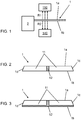
Figure 1 schematically shows a part of an apparatus in accordance with the present invention; -
Figure 2 shows a schematic cross-sectional view of a first embodiment of a semifinished product whereon the method according to the present invention can be carried out; -
Figure 3 shows a schematic cross-sectional view of a second embodiment of a semifinished product whereon the method according to the present invention can be carried out; -
Figure 4 shows a block diagram representing an apparatus in accordance with the present invention; -
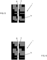
Figures 5-6 schematically show images used in the method and apparatus according to the present invention; -
Figures 5a-6a schematically show further images used in the method and apparatus according to the present invention. - With reference to the annexed drawings,
reference numeral 1 designates as a whole a semifinished product suitable for use in a tyre building process. - The
semifinished product 1 comprises at least afirst component 11 and asecond component 12. Thefirst component 11 is made of a first material, whereas thesecond component 12 is made of a second material, different from said first material. - Preferably, the
semifinished product 1 has a flat shape, which is delimited by atop surface 1a, abottom surface 1b and at least twoside surfaces Figures 2, 3 ). - By way of example, the
semifinished product 1 can be used for making tread bands for tyres. More in detail, thesemifinished product 1, when cut to size, can form a plurality of tread bands. - By way of example, the
second component 12 is a conductive insert associated with a tread band. Thefirst component 11 may thus form the remaining part of the tread band structure, made of elastomeric material. - The following description of the
semifinished product 1 is of course applicable to any semifinished product (comprising at least a first component and a second component) to be used for building any structural component of a tyre, without being limited to tread bands. Thesemifinished product 1 is provided at the exit of anextrusion assembly 2. - In one embodiment, the
first component 11 and thesecond component 12 are extruded by means of separate extrusion screws, and are then associated with each other as schematically shown inFigure 2 . In this case, thesecond component 12 extends essentially only through thefirst component 11, emerging through thetop surface 1a and thebottom surface 1b. - In another embodiment, the
first component 11 and thesecond component 12 are coextruded, thus forming the semifinished product schematically shown inFigure 3 . In this case, thesecond component 12 extends along thebottom surface 1b of the semifinished product and through thefirst component 11 in a substantially central position, emerging through thetop surface 1a of the same semifinished product. - Note that the
extrusion assembly 2 comprises the whole per se known structure necessary for producing thesemifinished product 1. - During the extrusion process carried out in the
extrusion assembly 2, thesemifinished product 1 accumulates heat. - As will become more apparent in the following, at the end of the extrusion process it is possible, thanks to the radiations detected as said heat is released, to analyze the integrity of the
semifinished product 1. - In particular, at least a first verification is carried out.
- The purpose of the first verification is to verify the presence of the
second component 12. - In other words, it is verified if the
second component 12 is present and emerges correctly through the surface of thesemifinished product 1. - In addition or as an alternative, the first verification aims at verifying the arrangement of the
second component 12 relative to thefirst component 11. - It is thus verified, for example, if the
second component 12 has been correctly arranged along a median longitudinal axis of thesemifinished product 1. - More in detail, the first verification comprises detecting first electromagnetic radiations R1. The first radiations R1 are essentially due to the emission, from the
semifinished product 1, of the heat accumulated during the extrusion process. - Preferably, the first radiations R1 are radiations emitted essentially from the
top surface 1a of thesemifinished product 1. - Preferably, the first radiations R1 are infrared radiations.
- Preferably, the detection of said first radiations R1 will subsequently generate first images G1, G2, ..., Gn.
- Preferably, each one of said first images G1, G2, ..., is generated by detecting radiations substantially within the same time interval.
- More specifically, each one of said first images G1, G2, ..., Gn represents a thermographic image taken at a given time instant.
- In other words, as will be further described below, the first radiations R1 can be detected by a thermal camera (first detection device 110). Each first image G1, G2, ..., Gn is generated by detecting radiations that allow the generation of a thermographic image.
- Preferably, the first radiations R1 are acquired at a frequency comprised between 10 Hz and 150 Hz.
- By way of example,
Figures 5 and5a schematically show a thermographic image corresponding to one of the first images G1, G2, ..., Gn. - In accordance with the invention, first detection parameters DP1 are determined on the basis of the first radiations R1.
- Preferably, the first detection parameters DP1 are representative of the presence of the
second component 12. - In addition or as an alternative, the first detection parameters DP1 are representative of the arrangement of the
second component 12 relative to thefirst component 11. - More in detail, it is verified, based on the first radiations R1, if the
semifinished product 1 comprises at least one first portion A, having a first temperature T1, and one second portion B, having a second temperature T2. It is then verified if a difference between the first temperature T1 and the second temperature T2 exceeds a predefined first threshold TH1; depending on this latter verification, a first operating parameter OP1 is then generated. - In practice, the first portion A may correspond to the
first component 11, and the second portion B may correspond to the second component 12: if a certain temperature difference is verified, it means that there are two different materials that are cooling down according to different dynamics. Such different materials may thus correspond to the materials used for making the first andsecond components - The first operating parameter OP1 may thus be representative of the outcome of this analysis: if the presence of the second portion B, i.e. the
second component 12, is ascertained, then the first operating parameter OP1 will have a certain value; if, on the contrary, the second portion B, i.e. thesecond component 12, is not detected, then the first operating parameter OP1 will have a value that will be different from said predefined value. - Note that the analysis represented by the first operating parameter OP1 aims at verifying if the
second component 12 emerges correctly from the surface of the semifinished product 1: the "presence" of the second portion B should therefore be understood as "presence on the outer surface of thesemifinished product 1". As a matter of fact, thesecond component 12 might actually be present within thesemifinished product 1 without however emerging through the surface thereof, in which case it will not be detected correctly. -
Figure 5 schematically shows the first portion A and the second portion B, identified in a thermographic image G1, G2, ...Gn obtained on the basis of the detection of the first radiations R1, wherein thesecond component 12 has been detected correctly. - On the contrary,
Figure 5a shows, in a similar fashion, the first portion A and the second portion B, identified in a thermographic image G1, G2, ...Gn obtained on the basis of the detection of the first radiations R1, wherein thesecond component 12 has not been detected correctly, since it does not properly emerge on the outer surface of the semifinished product 1 (e.g. thetop surface 1a). - The Applicant wishes to point out that the difference between the first and second temperatures T1, T2, when the
second component 12 is a conductive insert, may be comprised between about 4°C and 6 °C; the Applicant also wishes to remark that such values are much greater than the tolerance thresholds of commercially available thermal cameras, and therefore such temperature difference can be sensed with a high degree of reliability. - The applicant also wishes to point out that the position of the thermal camera can be selected essentially at will, due to the features of the commercial thermal cameras currently available on the market. More specifically, the thermal camera can be positioned at a variable height from the top/bottom surface of the
semifinished product 1 of, for example, approximately 30 cm to 2.5 m (this range being the one most commonly used, essentially depending on the technical specifications of the thermal cameras and optics currently available), either near theextrusion assembly 2 or a few metres away from it, provided that thesemifinished product 1 has not yet begun undergoing the liquid cooling process (generally using water). For example, during the air cooling that starts at the extrusion outlet, thefirst component 11 and thesecond component 12 will cool down according to sufficiently different dynamics so as to be still detectable, as previously illustrated, without much difficulty by modern thermal cameras. - Based on the first radiations R1, it is also possible to verify if the second portion B is in a predefined position relative to the first portion A. In particular, after the first and second portions A, B have been identified, it is determined if the mutual positions of the same correspond to a predetermined arrangement. For example, it is verified if the second portion B is arranged along a median longitudinal axis of the
semifinished product 1. As a function of this verification, a first verification parameter VP1 is then generated, the values of which will depend on whether the second portion B is correctly arranged relative to the first portion A or not. - A further verification that can be carried out on the basis of the first radiations R1 concerns the dimensions of the first portion A and/or the dimensions of the second portion B: preferably, once the first and second portions A, B have been identified, their dimensions are determined; such dimensions are then compared with pre-stored data, and a second verification parameter VP2 is generated as a function of such comparison.
- In practice, the second verification parameter VP2 will take preset values representative of the fact that the first portion and/or the second portion A, B have the desired dimensions. Based on said first radiations R1, first detection parameters DP1 are generated.
- The first detection parameters DP1 comprise one or more of the above-mentioned first operating parameter OP1, first verification parameter VP1, second verification parameter VP2.
- Preferably, the first detection parameters DP1 comprise the first operating parameter OP1, the first verification parameter VP1, and also the second verification parameter VP2.
- A first notification signal NS1 is generated as a function of the first detection parameters DP1.
- Advantageously, the first notification signal NS1 is representative of the admissibility or inadmissibility of the
semifinished product 1, or at least a part thereof, as concerns the presence, dimensions and/or arrangement of the first andsecond components - The first notification signal NS1 may comprise, for example, a visual and/or audible signal aimed at drawing the attention of an operator in the event that the production of a semifinished product should be interrupted because of errors/defects.
- In addition or as an alternative, the first notification signal NS1 may be configured for automatically stopping the extrusion of the
semifinished product 1. - In addition or as an alternative, the first notification signal NS1 may simply contain the information about the quality of the
semifinished product 1 in terms of presence/arrangement of its components. Such information may be stored for further processing. - As said above, the detection of the first radiations R1 originates a plurality of thermographic images G1, G2, ..., Gn.
- Advantageously, a respective first identification code ID1 is associated with each first image G1, G2, ..., Gn.
- Said first identification code ID1 is conveniently used for associating the thermographic image with the portion of semifinished product represented therein.
- By way of example, the first identification code ID1 may be obtained through an
encoder 130, the rotation of which is associated with the advance of thesemifinished product 1 as it exits theextrusion assembly 2. The first identification code ID1 is thus determined in a progressive manner, so that thermographic images taken sequentially over time will be associated with portions ofsemifinished product 1 extruded in the same succession. Preferably, a first notification signal NS1 is generated for each first image G1, G2, ..., Gn. In this manner, the outcome of the analysis carried out on each thermographic image will be made available. - Advantageously, a storing step is carried out, during which the following is stored for each first image G1, G2, ..., Gn:
- the first identification code ID1, and
- a first datum D1, representative of the respective first notification signal NS1.
- It will thus be possible to go back to errors or defects even after the end of the extrusion process, e.g. when the
semifinished product 1 has been wound into coils or cut to size for storage. - Preferably, the analysis of the
semifinished product 1 comprises a first sub-step, wherein the first notification signal NS1 is generated during the extrusion process. It will thus be possible to detect substantially in real time any problems related to the presence and/or arrangement of the components of the semifinished product, so that the extrusion process can be interrupted, if necessary, to avoid producing other semifinished products that will then have to be discarded. - Preferably, the analysis of the
semifinished product 1 comprises a second sub-step, carried out after the extrusion is complete: this second analysis (also called "batch" or "offline" analysis) can advantageously take into consideration all of the thermographic images taken during the extrusion process, so that more in-depth and complex (statistic) verifications can be made, compared to those carried out in real time while thesemifinished product 1 is being extruded. - By way of example, in the second sub-step the images acquired during the extrusion process are used for reconstructing via software a total image of the semifinished product manufactured. More specifically, an image of every single production batch is reconstructed from start to end, without any time and/or size limitations. In this reconstructed image, the
second component 12 is checked from production start to production end. In particular, continuity and temperature variations are analyzed throughout the production process. The image thus analyzed allows validating the whole production batch, and can be saved into the production data collection system along with the analysis just made. - As aforementioned, the first radiations R1 are preferably radiations emitted essentially from the
top surface 1a of thesemifinished product 1. - In one embodiment of the invention, e.g. applicable to the case wherein the
semifinished product 1 has the structure schematically shown inFigure 3 , the analysis based only on the first radiations R1 may be sufficient to evaluate the structural correctness of thesemifinished product 1. - In a different embodiment, e.g. applicable to the case wherein the
semifinished product 1 has the structure schematically shown inFigure 2 , a second verification may be carried out, which is based on radiations emitted from thebottom surface 1b of thesemifinished product 1, in a manner wholly similar to the above-described first verification. - The second verification aims at verifying at least one of:
- presence of the
second component 12; and - arrangement of the
second component 12 relative to thefirst component 11. - The second verification preferably comprises detecting second radiations R2, substantially emitted from the
bottom surface 1b of thesemifinished product 1. - Such second radiations R2 are emitted while the
semifinished product 1 is releasing the heat accumulated during the extrusion carried out in theextrusion assembly 2. - Preferably, the second radiations R2 are infrared radiations.
- Preferably, the detection of said second radiations R2 will subsequently generate second images HI, H2, ..., Hn.
- Preferably, each one of said second images HI, H2, ..., Hn is generated by detecting radiations substantially within the same time interval.
- Preferably, the second radiations R2 are acquired at a frequency comprised between 10 Hz and 150 Hz.
- By way of example,
Figures 6 and6a schematically show a thermographic image corresponding to one of the second images HI, H2, ..., Hn. - In other words, as will be further described below, the second radiations R2 can be detected by a thermal camera (second detection device 140). Each second image HI, H2, ..., Hn is generated by detecting radiations that allow the generation of a thermographic image.
- Based on the second radiations R2, second detection parameters DP2 are generated, which are representative of the presence of the
second component 12 and/or of the arrangement of thesecond component 12 relative to thefirst component 11. - More in detail, on the basis of the second radiations R2 it is verified if the
semifinished product 1 includes at least one third portion C having a third temperature T3 and one fourth portion D having a fourth temperature T4. It is then verified if a difference between the third temperature T3 and the fourth temperature T4 is greater than a second threshold TH2, and a corresponding second operating parameter OP2 is generated. - In practice, the third portion C may correspond to the
first component 11, and the fourth portion D may correspond to thesecond component 12. - If the third and fourth portions C, D, having the above-defined thermal characteristics, are identified, then the second operating parameter OP2 will have a value representative of the fact that the
second component 12 is present. - For example,
Figure 6 schematically shows the third portion C and the fourth portion D, identified in a thermographic image HI, H2, ...Hn obtained on the basis of the detection of the second radiations R2, wherein thesecond component 12 has been detected correctly. - On the contrary,
Figure 6a shows, in a similar fashion, the third portion C and the fourth portion D, identified in a thermographic image HI, H2, ...Hn obtained on the basis of the detection of the second radiations R2, wherein thesecond component 12 has not been detected correctly, since it does not fully emerge on the outer surface of the semifinished product 1 (e.g. thebottom surface 1b). - In addition or as an alternative, it is possible to verify, on the basis of the second radiations R2 detected, if the fourth portion D is in a predefined position relative to the third portion C. A corresponding third verification parameter VP3 is then generated, which is representative of the outcome of this part of the analysis.
- It can also be verified, on the basis of the second radiations R2 detected, if the third portion C and/or the fourth portion D have predefined dimensions. Following this part of the analysis, a corresponding fourth verification parameter VP4 is generated.
- Advantageously, the above-mentioned second detection parameters DP2 comprise one or more of the second operating parameter OP2, the third verification parameter VP3, and the fourth verification parameter VP4.
- Preferably, the second detection parameters DP2 comprise the second operating parameter OP2, the third verification parameter VP3, and also the fourth verification parameter VP4.
- As a function of the second detection parameters DP2, a second notification signal NS2 is generated, the meaning of which is wholly similar to that of the above-mentioned first notification signal NS1, though it refers to the
bottom surface 1b of thesemifinished product 1. - As aforementioned, the detection of the second radiations R2 originates a plurality of thermographic images HI, H2, ..., Hn.
- Advantageously, a respective second identification code ID2 is associated with each second image HI, H2, ..., Hn.
- Said second identification code ID2 is conveniently used for associating the thermographic image with the portion of
semifinished product 1 represented therein. - By way of example, the second identification code ID2 can be obtained through the above-mentioned
encoder 130, just like the first identification code ID1. - Preferably, a second notification signal NS2 is generated for each second image HI, H2, ..., Hn. In this manner, the outcome of the analysis carried out on each thermographic image will be made available.
- Advantageously, a storing step is carried out, during which the following is stored for each second image HI, H2, ..., Hn:
- the second identification code ID2, and
- a second datum D2, representative of the respective second notification signal NS2. Preferably, the second verification comprises a first sub-step, wherein the second notification signal NS2 is generated during the extrusion process.
- Preferably, the second verification comprises a second sub-step, carried out after the extrusion is complete: this second analysis (also called "batch" or "offline" analysis) can advantageously take into consideration all of the thermographic images taken during the extrusion process, so that more in-depth and complex (statistic) verifications can be made, compared to those carried out in real time while the
semifinished product 1 is being extruded. The method according to the invention can advantageously be implemented by anapparatus 100, schematically shown inFigure 4 . - The
apparatus 100 comprises, first of all, at least the above-mentionedfirst detection device 110 for detecting the first electromagnetic radiations R1. - Preferably, the
first detection device 110 substantially faces towards thetop surface 1a of thesemifinished product 1, and detects the first electromagnetic radiations R1 emitted from saidtop surface 1a. - Preferably, the
apparatus 100 further comprises thesecond detection device 140. - Preferably, the
second detection device 140 substantially faces towards thebottom surface 1b of thesemifinished product 1, and detects the second radiations R2 emitted from saidbottom surface 1b. - The
apparatus 100 further comprises aprocessing unit 120 associated with thefirst detection device 110 and, preferably, with thesecond detection device 140. - The
processing unit 120 is configured for determining the first detection parameters DP1 on the basis of the first radiations R1, and, preferably, the second detection parameters DP2 on the basis of the second radiations R2. - In particular, the
processing unit 120 is configured for determining one or more of the following: - the first
operating parameter OP 1; - the first verification parameter VP1;
- the second verification parameter VP2.
- Preferably, the
processing unit 120 is configured for determining the first operating parameter OP1, the first verification parameter VP1, and also the second verification parameter VP2. - In particular, the
processing unit 120 is configured for determining one or more of the following: - the second operating parameter OP2;
- the third verification parameter VP3;
- the fourth verification parameter VP4.
- Preferably, the
processing unit 120 is configured for determining the second operating parameter OP2, the third verification parameter VP3, and also the fourth verification parameter VP4. - The
processing unit 120 is preferably configured for generating said first notification signal NS1 on the basis of the first detection parameters DP1. - The
processing unit 120 is preferably configured for generating said second notification signal NS2 on the basis of the second detection parameters DP2. - Preferably, the
apparatus 100 comprises also theencoder 130. - The
encoder 130 is associated with theextrusion assembly 2, so that the rotation of theencoder 130 will be associated with the advance of thesemifinished product 1 exiting theextrusion assembly 2. - Thanks to the
encoder 130, it is possible to associate the respective first identification code ID1 with each first image G1, G2, ..., Gn, and, preferably, the respective second identification code ID2 with each second image HI, H2, ..., Hn. - Preferably, the
apparatus 100 is associated with astorage medium 150, which may be either integrated into or connected to theapparatus 100. - The
storage medium 150 can advantageously store the first identification code ID1 and the respective first datum D1 for each first image G1, G2, ..., Gn. - The
storage medium 150 can advantageously store the second identification code ID2 and the respective second datum D2 for each second image HI, H2, ..., Hn.
Claims (15)
- Method for controlling the extrusion of a semifinished product in a tyre building process, said method comprising:➢ providing a semifinished product (1) at the exit of an extrusion assembly (2), said semifinished product (1) comprising at least:a first component (11) made of at least one first material;a second component (12) made of at least one second material, different from said first material;said semifinished product (1) having accumulated heat during an extrusion carried out in said extrusion assembly (2);➢ making a first verification for verifying at least one of:presence of said second component (12);arrangement of said second component (12) relative to said first component (11),wherein said first verification comprises:detecting first electromagnetic radiations (R1) representative of a heat emission from said semifinished product (1) while said semifinished product (1) is releasing said accumulated heat;
based on said first radiations (R1) detected, determining first detection parameters (DP1) representative of at least one of the presence of said second component (12) and the arrangement of said second component (12) relative to said first component (11). - Method according to claim 1, wherein a first notification signal (NS1) is generated as a function of said first detection parameters (DP1).
- Method according to claim 1, wherein determining said first detection parameters (DP1)comprises:➢ based on said first radiations (R1) detected:verifying if said semifinished product (1) has at least one first portion (A) corresponding to said first component (11) and having a first temperature (T1);verifying if said semifinished product (1) has at least one second portion (B) corresponding to said second component (12) and having a second temperature (T2);➢ verifying if a difference between said first temperature (T1) and said second temperature (T2) is greater than a first threshold (TH1);➢ generating a first operating parameter (OP1) representative of the verification carried out in the previous step;said first detection parameters (DP1)comprising said first operating parameter (OP1).
- Method according to claim 3, wherein determining said first detection parameters (DP1)comprises: verifying if said second portion (B) is in a predefined position relative to said first portion (A), and generating a corresponding first verification parameter (VP1), said first detection parameters (DP1)comprising said first verification parameter (VP1).
- Method according to claim 3 or 4, wherein determining said first detection parameters (DP1)comprises:verifying if at least one of said first portion (A) and said second portion (B) has predefined dimensions, and generating a corresponding second verification parameter (VP2),said first detection parameters (DP1)comprising said second verification parameter (VP2).
- Method according to any one of the preceding claims, wherein said first verification comprises at least one sub-step which is carried out during said extrusion and a second sub-step which is carried out after said extrusion has been completed.
- Method according to any one of the preceding claims, wherein, through said detection of said first electromagnetic radiations (R1), first images (G1, G2, ..., Gn) are generated, each one of said first images (G1, G2, ..., Gn) being generated by detecting electromagnetic radiations substantially within the same time interval.
- Method according to claim 7 when dependent on claim 2, wherein said first verification comprises associating a respective first identification code (ID1) with each first image (G1, G2, ..., Gn), wherein said first notification signal (NS1) is generated for each first image (G1, G2, ..., Gn), said method comprising storing, for each first image (G1, G2, ..., Gn), the first identification code (ID1) associated with said first image and a first datum (D1) representative of the respective first notification signal (NS1).
- Method according to any one of the preceding claims, wherein said semifinished product (1) has a flat shape, which is delimited by a top surface (1a), a bottom surface (1b) and at least two side surfaces (1c, Id), wherein said first electromagnetic radiations (R1) are substantially emitted from said top surface (1a), wherein second electromagnetic radiations (R2), representative of a heat emission from said semifinished product (1) while said semifinished product (1) is releasing said accumulated heat, are substantially emitted from said bottom surface (1b), wherein a second verification is carried out for verifying at least one of:presence of said second component (12);arrangement of said second component (12) relative to said first component (11), wherein said second verification comprises:detecting said second electromagnetic radiations (R2); based on said second radiations (R2) detected, determining second detection parameters (DP2) representative of at least one of the presence of said second component (12) and the arrangement of said second component (12) relative to said first component (11).
- Method according to any one of the preceding claims, wherein said semifinished product (1), when cut to size, forms a plurality of tread bands.
- Method according to claim 10, wherein said second component (12) is a conductive insert associated with a tread band.
- Apparatus adapted for controlling the extrusion of a semifinished product in a tyre building process, wherein a semifinished product (1) at the exit of an extrusion assembly (2) comprises at least:➢ a first component (11) made of at least one first material;➢ a second component (12) made of at least one second material, different from said first material;said semifinished product (1) having accumulated heat during an extrusion carried out in said extrusion assembly (2);said apparatus (100) being adapted to carry out a first verification for verifying at least one of:presence of said second component (12);arrangement of said second component (12) relative to said first component (11),said apparatus (100) comprising:➢ at least one first detection device (110) adapted to detect first electromagnetic radiations (R1) representative of a heat emission from said semifinished product (1) while said semifinished product (1) is releasing said accumulated heat;➢ a processing unit (120) associated with said at least one first detection device (110) and configured for:
determining, based on said first radiations (R1) detected, first detection parameters (DP1) representative of at least one of the presence of said second component (12) and the arrangement of said second component (12) relative to said first component (11). - Apparatus according to claim 12, wherein said processing unit (120) is configured for generating a first notification signal (NS1) as a function of said first detection parameters (DP1).
- Apparatus according to claim 12, wherein said first electromagnetic radiations (R1) detected generate first images (G1, G2, ..., Gn), each one of said first images (G1, G2, ..., Gn) being generated by radiations which are detected substantially within the same time interval.
- Apparatus according to any one of claims 12-14, wherein said semifinished product (1) has a flat shape, which is delimited by a top surface (1a), a bottom surface (1b)and at least two side surfaces (1c, Id), wherein said first detection device (110) is configured for detecting the first electromagnetic radiations (R1) emitted from said top surface (1a), said first detection device (110) substantially facing said top surface (1a), wherein a second detection device (140) is included, which is configured for detecting second electromagnetic radiations (R2) representative of a heat emission from said semifinished product (1) while said semifinished product (1) is releasing said accumulated heat, emitted from said bottom surface (1b), said second detection device (140) substantially facing said bottom surface (1b), wherein said apparatus (1) is configured for carrying out a second verification for verifying at least one of:presence of said second component (12);arrangement of said second component (12) relative to said first component (11),
wherein said processing unit (120) is associated with said second detection element (140) and is configured for:
determining, based on said second radiations (R2) detected, second detection parameters (DP2) representative of at least one of the presence of said second component (12) and the arrangement of said second component (12) relative to said first component (11).
Applications Claiming Priority (2)
| Application Number | Priority Date | Filing Date | Title |
|---|---|---|---|
| ITUB20151231 | 2015-06-12 | ||
| PCT/IB2016/053366 WO2016199037A1 (en) | 2015-06-12 | 2016-06-08 | Method and apparatus for controlling the extrusion of a semifinished product in a tyre building process |
Publications (2)
| Publication Number | Publication Date |
|---|---|
| EP3307512A1 EP3307512A1 (en) | 2018-04-18 |
| EP3307512B1 true EP3307512B1 (en) | 2021-11-24 |
Family
ID=54199934
Family Applications (1)
| Application Number | Title | Priority Date | Filing Date |
|---|---|---|---|
| EP16739560.7A Active EP3307512B1 (en) | 2015-06-12 | 2016-06-08 | Method and apparatus for controlling the extrusion of a semifinished product in a tyre building process |
Country Status (6)
| Country | Link |
|---|---|
| EP (1) | EP3307512B1 (en) |
| CN (1) | CN107912028B (en) |
| BR (1) | BR112017025951B1 (en) |
| MX (1) | MX2017015611A (en) |
| RU (1) | RU2711440C2 (en) |
| WO (1) | WO2016199037A1 (en) |
Cited By (1)
| Publication number | Priority date | Publication date | Assignee | Title |
|---|---|---|---|---|
| US20240019388A1 (en) * | 2022-07-12 | 2024-01-18 | The Steelastic Company, Llc | Defect detection of extruded strip |
Families Citing this family (4)
| Publication number | Priority date | Publication date | Assignee | Title |
|---|---|---|---|---|
| US20200198414A1 (en) * | 2018-12-19 | 2020-06-25 | The Goodyear Tire & Rubber Company | Method and apparatus for forming a composite tread with microchimneys |
| US11541691B2 (en) | 2018-12-19 | 2023-01-03 | The Goodyear Tire & Rubber Company | Composite tread with targeted stiffness gradient and method of making |
| US11993110B2 (en) | 2018-12-19 | 2024-05-28 | The Goodyear Tire & Rubber Company | Reinforced tread and method of forming |
| JP7406134B2 (en) * | 2022-03-31 | 2023-12-27 | 横浜ゴム株式会社 | Tire component manufacturing method and system |
Citations (2)
| Publication number | Priority date | Publication date | Assignee | Title |
|---|---|---|---|---|
| GB2296335A (en) * | 1994-12-22 | 1996-06-26 | Sumitomo Rubber Ind | A method of checking the structural integrity of tyres |
| WO2011159280A2 (en) * | 2010-06-15 | 2011-12-22 | Michelin Recherche Et Technique, S.A. | Tire surface anomaly detection |
Family Cites Families (6)
| Publication number | Priority date | Publication date | Assignee | Title |
|---|---|---|---|---|
| US4097566A (en) * | 1977-06-01 | 1978-06-27 | Nucleonics Data Systems | Extrusion line control system |
| DE3315184C1 (en) * | 1983-04-27 | 1984-06-28 | Hermann Berstorff Maschinenbau Gmbh, 3000 Hannover | Method and extrusion device for monitoring the production of profiles from one or more rubber or plastic mixtures |
| SU1657955A2 (en) * | 1989-03-01 | 1991-06-23 | Предприятие П/Я Р-6594 | Device for regulating wall thickness of pipes |
| US5128077A (en) * | 1991-02-12 | 1992-07-07 | General Tire, Inc. | Method for producing multicomponent extrusions having controlled component contributions |
| KR100991443B1 (en) * | 2008-11-20 | 2010-11-03 | 한국타이어 주식회사 | Heating device for extrudate, semi-finished tire |
| ITMI20121613A1 (en) * | 2012-09-27 | 2014-03-28 | Pirelli | METHOD FOR THE CONTROL OF THE PRODUCTION OF TIRES FOR VEHICLE WHEELS |
-
2016
- 2016-06-08 CN CN201680032713.3A patent/CN107912028B/en active Active
- 2016-06-08 EP EP16739560.7A patent/EP3307512B1/en active Active
- 2016-06-08 BR BR112017025951-6A patent/BR112017025951B1/en active IP Right Grant
- 2016-06-08 WO PCT/IB2016/053366 patent/WO2016199037A1/en not_active Ceased
- 2016-06-08 MX MX2017015611A patent/MX2017015611A/en unknown
- 2016-06-08 RU RU2017142972A patent/RU2711440C2/en active
Patent Citations (2)
| Publication number | Priority date | Publication date | Assignee | Title |
|---|---|---|---|---|
| GB2296335A (en) * | 1994-12-22 | 1996-06-26 | Sumitomo Rubber Ind | A method of checking the structural integrity of tyres |
| WO2011159280A2 (en) * | 2010-06-15 | 2011-12-22 | Michelin Recherche Et Technique, S.A. | Tire surface anomaly detection |
Cited By (1)
| Publication number | Priority date | Publication date | Assignee | Title |
|---|---|---|---|---|
| US20240019388A1 (en) * | 2022-07-12 | 2024-01-18 | The Steelastic Company, Llc | Defect detection of extruded strip |
Also Published As
| Publication number | Publication date |
|---|---|
| EP3307512A1 (en) | 2018-04-18 |
| RU2017142972A (en) | 2019-07-15 |
| WO2016199037A1 (en) | 2016-12-15 |
| RU2711440C2 (en) | 2020-01-17 |
| BR112017025951B1 (en) | 2022-01-18 |
| BR112017025951A2 (en) | 2018-08-14 |
| MX2017015611A (en) | 2018-04-24 |
| CN107912028B (en) | 2020-03-31 |
| RU2017142972A3 (en) | 2019-11-06 |
| CN107912028A (en) | 2018-04-13 |
Similar Documents
| Publication | Publication Date | Title |
|---|---|---|
| WO2016199037A1 (en) | Method and apparatus for controlling the extrusion of a semifinished product in a tyre building process | |
| SE435819B (en) | SET TO CONTROL THE FOIL JACKET IN A BLASPHOLY STRING SPRAYING DEVICE | |
| US10042349B2 (en) | Method and equipment for controlling a manufacturing process of a component of a tyre for vehicle wheels | |
| US9862159B2 (en) | Method for controlling the manufacturing of tyres for wheels of vehicles | |
| CN106457710B (en) | Method for controlling the quality of production of tires and apparatus for producing tires | |
| US20200156337A1 (en) | Temperature sensor, and method for producing pneumatic tire | |
| IT9021250A1 (en) | PROCEDURE AND EQUIPMENT FOR REGENERATING TIRES | |
| EP3083219B1 (en) | Method and apparatus to control manufacturing and feeding of semi-finished products in a tyre building process | |
| US20210308972A1 (en) | Apparatus for building and for checking a continuous elongated element of a tyre for vehicle wheels | |
| WO2014175175A1 (en) | Excess piece protrusion amount measurement method and excess piece protrusion amount measurement device | |
| CN109153204B (en) | Circumferential measurement in tire building processes and equipment | |
| JP4418757B2 (en) | Method and apparatus for balancing tire tread regeneration operation | |
| JP7099939B2 (en) | Tire member molding device, tire member inspection method and tire member manufacturing method | |
| BR102016014795B1 (en) | APPLIANCE FOR APPLYING A STRIP OF ELASTOMERIC MATERIAL TO A SURFACE | |
| CN119677628A (en) | Defect detection in extruded strips | |
| IT202000029222A1 (en) | Extrusion method of a semi-finished product in elastomeric material | |
| US20180104883A1 (en) | Method and system for making a plastic film | |
| KR101895287B1 (en) | Apparatus for retreading a remanufactured tires and method thereof | |
| KR20150116064A (en) | Tire cure time setting method | |
| US20240019388A1 (en) | Defect detection of extruded strip | |
| US20200070395A1 (en) | Method of forming an elastomeric strip | |
| JPH0341336A (en) | Method and device for analyzing defect of tire through nonuniformity along circumferential direction | |
| BR102016015396B1 (en) | nozzle and roller apparatus and method for forming an elastomeric strip | |
| JP2025129730A (en) | Tire manufacturing method and manufacturing system | |
| JP6891609B2 (en) | Tire manufacturing method and tire manufacturing system |
Legal Events
| Date | Code | Title | Description |
|---|---|---|---|
| STAA | Information on the status of an ep patent application or granted ep patent |
Free format text: STATUS: THE INTERNATIONAL PUBLICATION HAS BEEN MADE |
|
| PUAI | Public reference made under article 153(3) epc to a published international application that has entered the european phase |
Free format text: ORIGINAL CODE: 0009012 |
|
| STAA | Information on the status of an ep patent application or granted ep patent |
Free format text: STATUS: REQUEST FOR EXAMINATION WAS MADE |
|
| 17P | Request for examination filed |
Effective date: 20171114 |
|
| AK | Designated contracting states |
Kind code of ref document: A1 Designated state(s): AL AT BE BG CH CY CZ DE DK EE ES FI FR GB GR HR HU IE IS IT LI LT LU LV MC MK MT NL NO PL PT RO RS SE SI SK SM TR |
|
| AX | Request for extension of the european patent |
Extension state: BA ME |
|
| DAV | Request for validation of the european patent (deleted) | ||
| DAX | Request for extension of the european patent (deleted) | ||
| GRAP | Despatch of communication of intention to grant a patent |
Free format text: ORIGINAL CODE: EPIDOSNIGR1 |
|
| STAA | Information on the status of an ep patent application or granted ep patent |
Free format text: STATUS: GRANT OF PATENT IS INTENDED |
|
| RIC1 | Information provided on ipc code assigned before grant |
Ipc: B29C 48/92 20190101AFI20210422BHEP Ipc: B29C 48/07 20190101ALI20210422BHEP Ipc: B29C 48/16 20190101ALI20210422BHEP Ipc: B29C 48/18 20190101ALI20210422BHEP Ipc: B29D 30/52 20060101ALI20210422BHEP Ipc: G01N 25/72 20060101ALN20210422BHEP |
|
| INTG | Intention to grant announced |
Effective date: 20210510 |
|
| REG | Reference to a national code |
Ref country code: DE Ref legal event code: R079 Ref document number: 602016066567 Country of ref document: DE Free format text: PREVIOUS MAIN CLASS: B29C0047060000 Ipc: B29C0048920000 |
|
| GRAJ | Information related to disapproval of communication of intention to grant by the applicant or resumption of examination proceedings by the epo deleted |
Free format text: ORIGINAL CODE: EPIDOSDIGR1 |
|
| STAA | Information on the status of an ep patent application or granted ep patent |
Free format text: STATUS: REQUEST FOR EXAMINATION WAS MADE |
|
| GRAP | Despatch of communication of intention to grant a patent |
Free format text: ORIGINAL CODE: EPIDOSNIGR1 |
|
| STAA | Information on the status of an ep patent application or granted ep patent |
Free format text: STATUS: GRANT OF PATENT IS INTENDED |
|
| INTG | Intention to grant announced |
Effective date: 20210709 |
|
| RIC1 | Information provided on ipc code assigned before grant |
Ipc: B29C 48/92 20190101AFI20210628BHEP Ipc: B29C 48/07 20190101ALI20210628BHEP Ipc: B29C 48/16 20190101ALI20210628BHEP Ipc: B29C 48/18 20190101ALI20210628BHEP Ipc: B29D 30/52 20060101ALI20210628BHEP Ipc: G01N 25/72 20060101ALN20210628BHEP |
|
| GRAS | Grant fee paid |
Free format text: ORIGINAL CODE: EPIDOSNIGR3 |
|
| GRAA | (expected) grant |
Free format text: ORIGINAL CODE: 0009210 |
|
| STAA | Information on the status of an ep patent application or granted ep patent |
Free format text: STATUS: THE PATENT HAS BEEN GRANTED |
|
| AK | Designated contracting states |
Kind code of ref document: B1 Designated state(s): AL AT BE BG CH CY CZ DE DK EE ES FI FR GB GR HR HU IE IS IT LI LT LU LV MC MK MT NL NO PL PT RO RS SE SI SK SM TR |
|
| REG | Reference to a national code |
Ref country code: GB Ref legal event code: FG4D |
|
| REG | Reference to a national code |
Ref country code: AT Ref legal event code: REF Ref document number: 1449526 Country of ref document: AT Kind code of ref document: T Effective date: 20211215 |
|
| REG | Reference to a national code |
Ref country code: DE Ref legal event code: R096 Ref document number: 602016066567 Country of ref document: DE |
|
| REG | Reference to a national code |
Ref country code: IE Ref legal event code: FG4D |
|
| REG | Reference to a national code |
Ref country code: LT Ref legal event code: MG9D |
|
| REG | Reference to a national code |
Ref country code: NL Ref legal event code: MP Effective date: 20211124 |
|
| REG | Reference to a national code |
Ref country code: AT Ref legal event code: MK05 Ref document number: 1449526 Country of ref document: AT Kind code of ref document: T Effective date: 20211124 |
|
| PG25 | Lapsed in a contracting state [announced via postgrant information from national office to epo] |
Ref country code: RS Free format text: LAPSE BECAUSE OF FAILURE TO SUBMIT A TRANSLATION OF THE DESCRIPTION OR TO PAY THE FEE WITHIN THE PRESCRIBED TIME-LIMIT Effective date: 20211124 Ref country code: LT Free format text: LAPSE BECAUSE OF FAILURE TO SUBMIT A TRANSLATION OF THE DESCRIPTION OR TO PAY THE FEE WITHIN THE PRESCRIBED TIME-LIMIT Effective date: 20211124 Ref country code: FI Free format text: LAPSE BECAUSE OF FAILURE TO SUBMIT A TRANSLATION OF THE DESCRIPTION OR TO PAY THE FEE WITHIN THE PRESCRIBED TIME-LIMIT Effective date: 20211124 Ref country code: BG Free format text: LAPSE BECAUSE OF FAILURE TO SUBMIT A TRANSLATION OF THE DESCRIPTION OR TO PAY THE FEE WITHIN THE PRESCRIBED TIME-LIMIT Effective date: 20220224 Ref country code: AT Free format text: LAPSE BECAUSE OF FAILURE TO SUBMIT A TRANSLATION OF THE DESCRIPTION OR TO PAY THE FEE WITHIN THE PRESCRIBED TIME-LIMIT Effective date: 20211124 |
|
| PG25 | Lapsed in a contracting state [announced via postgrant information from national office to epo] |
Ref country code: IS Free format text: LAPSE BECAUSE OF FAILURE TO SUBMIT A TRANSLATION OF THE DESCRIPTION OR TO PAY THE FEE WITHIN THE PRESCRIBED TIME-LIMIT Effective date: 20220324 Ref country code: SE Free format text: LAPSE BECAUSE OF FAILURE TO SUBMIT A TRANSLATION OF THE DESCRIPTION OR TO PAY THE FEE WITHIN THE PRESCRIBED TIME-LIMIT Effective date: 20211124 Ref country code: PT Free format text: LAPSE BECAUSE OF FAILURE TO SUBMIT A TRANSLATION OF THE DESCRIPTION OR TO PAY THE FEE WITHIN THE PRESCRIBED TIME-LIMIT Effective date: 20220324 Ref country code: PL Free format text: LAPSE BECAUSE OF FAILURE TO SUBMIT A TRANSLATION OF THE DESCRIPTION OR TO PAY THE FEE WITHIN THE PRESCRIBED TIME-LIMIT Effective date: 20211124 Ref country code: NO Free format text: LAPSE BECAUSE OF FAILURE TO SUBMIT A TRANSLATION OF THE DESCRIPTION OR TO PAY THE FEE WITHIN THE PRESCRIBED TIME-LIMIT Effective date: 20220224 Ref country code: NL Free format text: LAPSE BECAUSE OF FAILURE TO SUBMIT A TRANSLATION OF THE DESCRIPTION OR TO PAY THE FEE WITHIN THE PRESCRIBED TIME-LIMIT Effective date: 20211124 Ref country code: LV Free format text: LAPSE BECAUSE OF FAILURE TO SUBMIT A TRANSLATION OF THE DESCRIPTION OR TO PAY THE FEE WITHIN THE PRESCRIBED TIME-LIMIT Effective date: 20211124 Ref country code: HR Free format text: LAPSE BECAUSE OF FAILURE TO SUBMIT A TRANSLATION OF THE DESCRIPTION OR TO PAY THE FEE WITHIN THE PRESCRIBED TIME-LIMIT Effective date: 20211124 Ref country code: GR Free format text: LAPSE BECAUSE OF FAILURE TO SUBMIT A TRANSLATION OF THE DESCRIPTION OR TO PAY THE FEE WITHIN THE PRESCRIBED TIME-LIMIT Effective date: 20220225 Ref country code: ES Free format text: LAPSE BECAUSE OF FAILURE TO SUBMIT A TRANSLATION OF THE DESCRIPTION OR TO PAY THE FEE WITHIN THE PRESCRIBED TIME-LIMIT Effective date: 20211124 |
|
| PG25 | Lapsed in a contracting state [announced via postgrant information from national office to epo] |
Ref country code: SM Free format text: LAPSE BECAUSE OF FAILURE TO SUBMIT A TRANSLATION OF THE DESCRIPTION OR TO PAY THE FEE WITHIN THE PRESCRIBED TIME-LIMIT Effective date: 20211124 Ref country code: SK Free format text: LAPSE BECAUSE OF FAILURE TO SUBMIT A TRANSLATION OF THE DESCRIPTION OR TO PAY THE FEE WITHIN THE PRESCRIBED TIME-LIMIT Effective date: 20211124 Ref country code: RO Free format text: LAPSE BECAUSE OF FAILURE TO SUBMIT A TRANSLATION OF THE DESCRIPTION OR TO PAY THE FEE WITHIN THE PRESCRIBED TIME-LIMIT Effective date: 20211124 Ref country code: EE Free format text: LAPSE BECAUSE OF FAILURE TO SUBMIT A TRANSLATION OF THE DESCRIPTION OR TO PAY THE FEE WITHIN THE PRESCRIBED TIME-LIMIT Effective date: 20211124 Ref country code: DK Free format text: LAPSE BECAUSE OF FAILURE TO SUBMIT A TRANSLATION OF THE DESCRIPTION OR TO PAY THE FEE WITHIN THE PRESCRIBED TIME-LIMIT Effective date: 20211124 Ref country code: CZ Free format text: LAPSE BECAUSE OF FAILURE TO SUBMIT A TRANSLATION OF THE DESCRIPTION OR TO PAY THE FEE WITHIN THE PRESCRIBED TIME-LIMIT Effective date: 20211124 |
|
| REG | Reference to a national code |
Ref country code: DE Ref legal event code: R097 Ref document number: 602016066567 Country of ref document: DE |
|
| PLBE | No opposition filed within time limit |
Free format text: ORIGINAL CODE: 0009261 |
|
| STAA | Information on the status of an ep patent application or granted ep patent |
Free format text: STATUS: NO OPPOSITION FILED WITHIN TIME LIMIT |
|
| PG25 | Lapsed in a contracting state [announced via postgrant information from national office to epo] |
Ref country code: AL Free format text: LAPSE BECAUSE OF FAILURE TO SUBMIT A TRANSLATION OF THE DESCRIPTION OR TO PAY THE FEE WITHIN THE PRESCRIBED TIME-LIMIT Effective date: 20211124 |
|
| 26N | No opposition filed |
Effective date: 20220825 |
|
| PG25 | Lapsed in a contracting state [announced via postgrant information from national office to epo] |
Ref country code: SI Free format text: LAPSE BECAUSE OF FAILURE TO SUBMIT A TRANSLATION OF THE DESCRIPTION OR TO PAY THE FEE WITHIN THE PRESCRIBED TIME-LIMIT Effective date: 20211124 |
|
| PG25 | Lapsed in a contracting state [announced via postgrant information from national office to epo] |
Ref country code: MC Free format text: LAPSE BECAUSE OF FAILURE TO SUBMIT A TRANSLATION OF THE DESCRIPTION OR TO PAY THE FEE WITHIN THE PRESCRIBED TIME-LIMIT Effective date: 20211124 |
|
| REG | Reference to a national code |
Ref country code: CH Ref legal event code: PL |
|
| REG | Reference to a national code |
Ref country code: BE Ref legal event code: MM Effective date: 20220630 |
|
| PG25 | Lapsed in a contracting state [announced via postgrant information from national office to epo] |
Ref country code: LU Free format text: LAPSE BECAUSE OF NON-PAYMENT OF DUE FEES Effective date: 20220608 Ref country code: LI Free format text: LAPSE BECAUSE OF NON-PAYMENT OF DUE FEES Effective date: 20220630 Ref country code: IE Free format text: LAPSE BECAUSE OF NON-PAYMENT OF DUE FEES Effective date: 20220608 Ref country code: CH Free format text: LAPSE BECAUSE OF NON-PAYMENT OF DUE FEES Effective date: 20220630 |
|
| PG25 | Lapsed in a contracting state [announced via postgrant information from national office to epo] |
Ref country code: BE Free format text: LAPSE BECAUSE OF NON-PAYMENT OF DUE FEES Effective date: 20220630 |
|
| PG25 | Lapsed in a contracting state [announced via postgrant information from national office to epo] |
Ref country code: HU Free format text: LAPSE BECAUSE OF FAILURE TO SUBMIT A TRANSLATION OF THE DESCRIPTION OR TO PAY THE FEE WITHIN THE PRESCRIBED TIME-LIMIT; INVALID AB INITIO Effective date: 20160608 |
|
| PG25 | Lapsed in a contracting state [announced via postgrant information from national office to epo] |
Ref country code: MK Free format text: LAPSE BECAUSE OF FAILURE TO SUBMIT A TRANSLATION OF THE DESCRIPTION OR TO PAY THE FEE WITHIN THE PRESCRIBED TIME-LIMIT Effective date: 20211124 Ref country code: CY Free format text: LAPSE BECAUSE OF FAILURE TO SUBMIT A TRANSLATION OF THE DESCRIPTION OR TO PAY THE FEE WITHIN THE PRESCRIBED TIME-LIMIT Effective date: 20211124 |
|
| PG25 | Lapsed in a contracting state [announced via postgrant information from national office to epo] |
Ref country code: TR Free format text: LAPSE BECAUSE OF FAILURE TO SUBMIT A TRANSLATION OF THE DESCRIPTION OR TO PAY THE FEE WITHIN THE PRESCRIBED TIME-LIMIT Effective date: 20211124 |
|
| PG25 | Lapsed in a contracting state [announced via postgrant information from national office to epo] |
Ref country code: MT Free format text: LAPSE BECAUSE OF FAILURE TO SUBMIT A TRANSLATION OF THE DESCRIPTION OR TO PAY THE FEE WITHIN THE PRESCRIBED TIME-LIMIT Effective date: 20211124 |
|
| PGFP | Annual fee paid to national office [announced via postgrant information from national office to epo] |
Ref country code: DE Payment date: 20250627 Year of fee payment: 10 |
|
| PGFP | Annual fee paid to national office [announced via postgrant information from national office to epo] |
Ref country code: GB Payment date: 20250627 Year of fee payment: 10 |
|
| PGFP | Annual fee paid to national office [announced via postgrant information from national office to epo] |
Ref country code: FR Payment date: 20250625 Year of fee payment: 10 |
|
| PGFP | Annual fee paid to national office [announced via postgrant information from national office to epo] |
Ref country code: IT Payment date: 20250619 Year of fee payment: 10 |