EP3307499B1 - Machines et procédés pour couper des produits - Google Patents
Machines et procédés pour couper des produits Download PDFInfo
- Publication number
- EP3307499B1 EP3307499B1 EP16808496.0A EP16808496A EP3307499B1 EP 3307499 B1 EP3307499 B1 EP 3307499B1 EP 16808496 A EP16808496 A EP 16808496A EP 3307499 B1 EP3307499 B1 EP 3307499B1
- Authority
- EP
- European Patent Office
- Prior art keywords
- impeller
- cutting head
- products
- machine
- interior
- Prior art date
- Legal status (The legal status is an assumption and is not a legal conclusion. Google has not performed a legal analysis and makes no representation as to the accuracy of the status listed.)
- Active
Links
- 238000005520 cutting process Methods 0.000 title claims description 101
- 238000000034 method Methods 0.000 title claims description 10
- 235000013305 food Nutrition 0.000 claims description 18
- 235000002595 Solanum tuberosum Nutrition 0.000 description 3
- 244000061456 Solanum tuberosum Species 0.000 description 3
- 230000000712 assembly Effects 0.000 description 3
- 238000000429 assembly Methods 0.000 description 3
- 238000010276 construction Methods 0.000 description 3
- 230000000737 periodic effect Effects 0.000 description 3
- 238000005469 granulation Methods 0.000 description 2
- 230000003179 granulation Effects 0.000 description 2
- 238000004519 manufacturing process Methods 0.000 description 2
- 239000000463 material Substances 0.000 description 2
- 235000013606 potato chips Nutrition 0.000 description 2
- 235000012015 potatoes Nutrition 0.000 description 2
- 235000013311 vegetables Nutrition 0.000 description 2
- 235000012773 waffles Nutrition 0.000 description 2
- 229920002472 Starch Polymers 0.000 description 1
- 238000005452 bending Methods 0.000 description 1
- 238000005422 blasting Methods 0.000 description 1
- 235000013351 cheese Nutrition 0.000 description 1
- 238000005336 cracking Methods 0.000 description 1
- 208000018999 crinkle Diseases 0.000 description 1
- 235000013365 dairy product Nutrition 0.000 description 1
- 235000013569 fruit product Nutrition 0.000 description 1
- 235000011389 fruit/vegetable juice Nutrition 0.000 description 1
- 239000007788 liquid Substances 0.000 description 1
- 235000013622 meat product Nutrition 0.000 description 1
- 230000007935 neutral effect Effects 0.000 description 1
- 235000014571 nuts Nutrition 0.000 description 1
- 230000001737 promoting effect Effects 0.000 description 1
- 235000019698 starch Nutrition 0.000 description 1
- 239000008107 starch Substances 0.000 description 1
- 238000011144 upstream manufacturing Methods 0.000 description 1
Images


Classifications
-
- B—PERFORMING OPERATIONS; TRANSPORTING
- B26—HAND CUTTING TOOLS; CUTTING; SEVERING
- B26D—CUTTING; DETAILS COMMON TO MACHINES FOR PERFORATING, PUNCHING, CUTTING-OUT, STAMPING-OUT OR SEVERING
- B26D7/00—Details of apparatus for cutting, cutting-out, stamping-out, punching, perforating, or severing by means other than cutting
- B26D7/06—Arrangements for feeding or delivering work of other than sheet, web, or filamentary form
- B26D7/0691—Arrangements for feeding or delivering work of other than sheet, web, or filamentary form by centrifugal force
-
- B—PERFORMING OPERATIONS; TRANSPORTING
- B26—HAND CUTTING TOOLS; CUTTING; SEVERING
- B26D—CUTTING; DETAILS COMMON TO MACHINES FOR PERFORATING, PUNCHING, CUTTING-OUT, STAMPING-OUT OR SEVERING
- B26D1/00—Cutting through work characterised by the nature or movement of the cutting member or particular materials not otherwise provided for; Apparatus or machines therefor; Cutting members therefor
- B26D1/01—Cutting through work characterised by the nature or movement of the cutting member or particular materials not otherwise provided for; Apparatus or machines therefor; Cutting members therefor involving a cutting member which does not travel with the work
- B26D1/02—Cutting through work characterised by the nature or movement of the cutting member or particular materials not otherwise provided for; Apparatus or machines therefor; Cutting members therefor involving a cutting member which does not travel with the work having a stationary cutting member
- B26D1/03—Cutting through work characterised by the nature or movement of the cutting member or particular materials not otherwise provided for; Apparatus or machines therefor; Cutting members therefor involving a cutting member which does not travel with the work having a stationary cutting member with a plurality of cutting members
-
- B—PERFORMING OPERATIONS; TRANSPORTING
- B26—HAND CUTTING TOOLS; CUTTING; SEVERING
- B26D—CUTTING; DETAILS COMMON TO MACHINES FOR PERFORATING, PUNCHING, CUTTING-OUT, STAMPING-OUT OR SEVERING
- B26D3/00—Cutting work characterised by the nature of the cut made; Apparatus therefor
- B26D3/28—Splitting layers from work; Mutually separating layers by cutting
-
- B—PERFORMING OPERATIONS; TRANSPORTING
- B26—HAND CUTTING TOOLS; CUTTING; SEVERING
- B26D—CUTTING; DETAILS COMMON TO MACHINES FOR PERFORATING, PUNCHING, CUTTING-OUT, STAMPING-OUT OR SEVERING
- B26D7/00—Details of apparatus for cutting, cutting-out, stamping-out, punching, perforating, or severing by means other than cutting
- B26D7/26—Means for mounting or adjusting the cutting member; Means for adjusting the stroke of the cutting member
- B26D7/2614—Means for mounting the cutting member
-
- B—PERFORMING OPERATIONS; TRANSPORTING
- B26—HAND CUTTING TOOLS; CUTTING; SEVERING
- B26D—CUTTING; DETAILS COMMON TO MACHINES FOR PERFORATING, PUNCHING, CUTTING-OUT, STAMPING-OUT OR SEVERING
- B26D1/00—Cutting through work characterised by the nature or movement of the cutting member or particular materials not otherwise provided for; Apparatus or machines therefor; Cutting members therefor
- B26D1/0006—Cutting members therefor
- B26D2001/006—Cutting members therefor the cutting blade having a special shape, e.g. a special outline, serrations
-
- B—PERFORMING OPERATIONS; TRANSPORTING
- B26—HAND CUTTING TOOLS; CUTTING; SEVERING
- B26D—CUTTING; DETAILS COMMON TO MACHINES FOR PERFORATING, PUNCHING, CUTTING-OUT, STAMPING-OUT OR SEVERING
- B26D2210/00—Machines or methods used for cutting special materials
- B26D2210/02—Machines or methods used for cutting special materials for cutting food products, e.g. food slicers
Definitions
- the present invention generally relates to methods and machines for cutting products.
- the invention particularly relates to machines equipped with a cutting head and an impeller adapted to rotate within the cutting head for transporting products to one or more knives mounted on the cutting head for cutting the products.
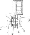
- FIG. 1 A widely used line of machines for this purpose is commercially available from Urschel Laboratories, Inc., under the name Urschel Model CC ® , an embodiment of which is schematically represented in FIG. 1 .
- the Model CC ® machine line provides versions of centrifugal-type slicers capable of producing uniform slices, strip cuts, shreds, and granulations of a wide variety of products at high production capacities.
- the Model CC ® line of machines can make use of substantially round potatoes to produce a desirable circular chip shape with a minimum amount of scrap.
- the Model CC ® machine 10 represented in FIG. 1 includes a cutting head 12 mounted on a support ring 15 above a gear box 16.
- the cutting head 12 is generally annular-shaped with cutting knives (not shown) mounted at its inner circumference.
- An impeller 14 is coaxially mounted within the cutting head 12 and has an axis 17 of rotation that coincides with an axis of the cutting head 12.
- the impeller 14 rotates about its axis 17 within the cutting head 12, while the latter remains stationary.
- the impeller 14 is rotationally driven by a shaft that is enclosed within a housing 18 and coupled to the gear box 16. Products are delivered to the cutting head 12 and impeller 14 through a feed hopper 11 located above the cutting head 12.
- the impeller 14 comprises generally radially-oriented paddles 13, each having a face that engages and directs the products radially outward toward and against the knives of the cutting head 12 as the impeller 14 rotates.
- Model CC ® machines have cutting heads with diameters of under fourteen inches (under 35 cm).
- Other aspects pertaining to the construction and operation of Model CC ® machines, including improved embodiments thereof, are described in U.S. Patent Nos. 5,694,824 and 6,968,765 .
- the present invention provides methods and equipment suitable for cutting products.
- a machine as defined in claim 1 is provided. According to an other aspect of the invention a method of using this machine is provided.
- FIG. 2 represents a nonlimiting example of a portion of a centrifugal-type cutting machine 50 similar to the Model CC ® machine 10 of FIG. 1 , though modified for reasons that will become apparent from the following discussion.
- FIGS. 3 and 4 represent, respectively, a cutting head 20 and an impeller 40 that, in accordance with nonlimiting embodiments of the present invention, are of types that can be used in the machine 50 of FIG. 2 , which schematically represents the cutting head 20 and impeller 40 enclosed within a housing 54. Though the cutting head 20, impeller 40, and machine 50 will be discussed in reference to cutting food products, it should be understood that the scope of the invention encompasses the ability to cut other types of products.
- the cutting head 20 is generally annular-shaped with cutting knives 22 ( FIG. 3 ) mounted and spaced about its perimeter.
- the impeller 40 is adapted to be rotated within the cutting head 20 about an axis 52 of rotation, while the cutting head 20 remains stationary.
- the impeller 40 is represented in FIG. 2 as coaxially mounted within the cutting head 20 such that its axis 52 approximately coincides with an axis of the cutting head 20 and an outer circumference of the impeller 40 is adjacent an inner circumference of the cutting head 20. Based on the configurations of the machine 50, cutting head 20 and impeller 40 shown in FIGS. 2 through 4 , the impeller 40 rotates clockwise within the cutting head 20 when viewed from above.
- Each knife 22 of the cutting head 20 projects radially inward toward the interior of the cutting head 20, generally in a direction opposite the rotation of the impeller 40, and defines a cutting edge at its radially innermost extremity.
- the cutting head 20 of FIG. 3 comprises a lower support ring 24, an upper support ring 26, and circumferentially-spaced support segments (shoes) 28 (one of which is omitted in FIG. 3 ).
- the knives 22 of the cutting head 20 are individually secured to the shoes 28 with clamping assemblies 30.
- Each clamping assembly 30 includes a knife holder 30A mounted to the radially inward-facing side of a shoe 28, and a clamp 30B mounted on the radially outward-facing side of the shoe 28 to secure the knife 22 to the knife holder 30A (some clamp assemblies 30 are shown in FIG. 3 without their clamps 30B in order to expose their knives 22 and holders 30A).
- the clamping assemblies 30 enable the knives 22 to be replaced without removing the head 20 from its housing 54.
- the shoes 28 are secured with bolts (not shown) or other suitable means to the support rings 24 and 26.
- the shoes 28 are equipped with coaxial pivot pins (not shown) that engage holes 32 (a pair of which is visible in FIG. 3 ) in the support rings 24 and 26.
- pivoting on its pins the orientation of a shoe 28 can be adjusted to alter the radial location of the cutting edge of its knife 22 with respect to the axis of the cutting head 20, thereby controlling the thickness of the sliced food product.
- adjustment can be achieved with an adjusting screw and/or pin 34 (one of which is shown in FIG. 3 ) located circumferentially behind the pivot pins.
- each gate insert strip 36 and its corresponding trailing knife 22 define a gate opening whose width can be adjusted by pivoting the shoe 28 toward and away from the cutting edge of the knife 22.
- the thickness of each slice produced by a knife 22 is determined by the gate opening, and specifically the radial distance between the cutting edge of a knife 22 and the adjacent trailing edge of a gate insert strip 36 preceding the knife 22.
- trailing refers to a position on a cutting head that follows or succeeds another in the direction of rotation of an impeller assembled with the cutting head
- leading refers to a position on a cutting head that is ahead of or precedes another in the direction opposite the impeller's rotation.
- the impeller 40 comprises generally radially-oriented paddles 42 disposed between a base 44 and an upper ring 46.
- the base 44 and ring 46 are represented in the embodiment of FIG. 4 as being parallel to each other and perpendicular to the rotational axis 52 of the impeller 40.
- the ring 46 defines an upper central opening 47 that provides an entrance through which food products enter an interior space of the impeller 40 defined by and between its base 44, ring 46, and outer circumference.
- the base 44 is entirely closed to receive and support food products introduced into the impeller 40.
- the paddles 42 have clockwise-facing faces 48 that engage and direct the food products radially outward toward and against the knives 22 of the cutting head 20 as the impeller 40 rotates within the cutting head 20.
- each paddle face 48 is preferably positive, meaning that the radially innermost extent of each paddle face 48 is angled toward the direction of rotation of the impeller 40 relative to a radial of the impeller 40.
- the pitch of the paddle faces 48 could be negative or neutral, the latter meaning that the face 48 of each paddle 42 entirely lies on a radial of the impeller 40.
- the knives 22 shown in FIG. 3 are depicted as having straight cutting edges for producing flat slices, though other shapes could be used to produce sliced, strip-cut, shredded, or granulated products.
- the knives 22 can have cutting edges that define a periodic pattern of peaks and valleys when viewed edgewise.
- the periodic pattern can be characterized by sharp peaks and valleys, or a more corrugated or sinusoidal shape characterized by more rounded peaks and valleys when viewed edgewise.
- each knife 22 If the peaks and valleys of each knife 22 are aligned with those of its leading knife 22, slices are produced in which each peak on one surface of a slice corresponds to a valley on the opposite surface of the slice, such that the slices are substantially uniform in thickness but have a cross-sectional shape that is characterized by sharp peaks and valleys ("V-slices”) or a more corrugated or sinusoidal shape (crinkle slices), collectively referred to herein as periodic shapes.
- V-slices sharp peaks and valleys
- crinkle slices a more corrugated or sinusoidal shape
- shredded food product can be produced if each peak of each knife 22 is aligned with a valley of its leading knife 22, and waffle/lattice-cut food product can be produced by intentionally making off-axis alignment cuts with a periodic-shaped knife, for example, by crosscutting a food product at two different angles, typically ninety degrees apart.
- strip-cut and granulated products can be produced with the use of additional knives and/or cutting wheels located downstream of the knives 22. Whether a sliced, strip-cut, shredded, granulated, or waffle/lattice-cut product is desired will depend on the desired shape or intended use of the product.
- the embodiment represented in FIGS. 2 through 4 differs in part from current commercial embodiments of Model CC ® machines in terms of the interior diameter of the cutting head 20 (defined by the inner circumference thereof) and the corresponding outer diameter of the impeller 40 (defined by the outer circumference thereof).
- the respective diameters of the cutting head 20 and impeller 40 exceed fourteen inches (about 35 cm), and preferably exceed twenty inches (about 50 cm).
- the respective diameters of the cutting head 20 and impeller 40 are about twenty-one inches (about 53 cm), allowing for a suitable diametric clearance therebetween.
- the diameters of the cutting head 20 and impeller 40 will typically be capable of promoting greater throughput (higher capacity) in comparison to smaller commercial embodiments of Model CC ® machines.
- the diameters of the cutting head 20 and impeller 40 also allow for the use of various alternative feeding methods that are not practical and may not be possible with smaller diameter cutting heads. For example, due to the larger diameters of the cutting head 20 and impeller 40, FIG.
- the machine 50 represents the machine 50 as equipped with a feed hopper 56 configured with a feeding apparatus 58 that directs products downward and then radially outward toward the outer circumference of the impeller 40, rather than simply dropping the products in the center of the impeller 40 and entirely relying on centrifugal force to cause the products to move outward into engagement with the paddles 42 of the impeller 40 and, thereafter, the knives 22 of the cutting head 20.
- the feeding apparatus 58 comprises an arcuately-tapering chute that extends downward into the impeller 40 and redirects the products radially outward toward the outer circumference of the impeller 40 as the products enter the interior of the impeller 40.
- the paddles 42 of the impeller 40 could be replaced with tubes or a chute associated with a feeding apparatus that extends downward into the impeller 40 and is capable of orienting the products as they are delivered to the outer circumference of the impeller 40.
- the hopper 56, feeding apparatus 58, and paddles 42 can be considered to be members of a delivery means or unit of the machine 50.
- FIG. 4 represents the face 48 of each paddle 42 as substantially planar with axially-oriented ribs or grooves that promote engagement and stability of the products during the cutting operation.
- the ribs/grooves are represented as being equi-spaced from each other, substantially parallel to each other, orientated substantially parallel to the axis 52 of the impeller 40, and continuous to an outward radial end of each paddle 42 at the outer circumference of the impeller 40.
- FIG. 4 further shows the ribs/grooves as occupying the entirety of each paddle face 48. It is within the scope that the ribs/grooves could be omitted or replaced with other surface features, including surface textures resulting from grit blasting the paddle faces 48.
- each paddle 42 has a length between its radially innermost and outermost extents of less than twenty percent, roughly about fifteen percent, of the radius of the impeller 40, which is attributable at least in part to the relatively large diameter of the impeller 40.
- the number of paddles 42 within the impeller 40 can also be varied, i.e., more or less than the eight paddles 42 shown for the embodiment in FIG. 4 .
- shoe height i.e., in the axial direction of the cutting head 20
- shoe height will typically be sized to accommodate the size of the product being cut but limited so as not to unnecessarily add unnecessary weight to the cutting head 20.
- the circumferential lengths and spacing of the shoes 28 preferably enable the food product to settle when being cut and between cutting operations performed by a pair of circumferentially successive shoes 28, and to ensure that the food product isn't being cut by two knives 22 at the same time.
- the cutting head 20 is shown in FIG. 3 as comprising twelve shoes 28 to which are mounted a corresponding number of knives 22.
- paddles 42 are preferably sized so that the axial height of the impeller 40 is less than the axial height of the cutting head 20, corresponding to the representation of the machine 50 in FIG. 2 .
- the head 20 will have a correspondingly low rake-off angle, such that slices leaving the knives 22 will tend to be relatively flat with reduced likelihood of cracking attributable to bending as the slices are coming off the knives 22.
- rake-off angle is measured as the angle that a slice must deviate relative to a tangent line that begins at an intersection defined by the knife edge and a path of a product sliding surface defined by the interior surface of a leading shoe 28, i.e., the shoe 28 immediately upstream of a particular knife 22. The line is then tangent to the radial product sliding surface of the leading shoe 28.
- the rake-off angle is a function of both the hardware and the gap setting at which the entire knife holder 30A, knife 22, and shoe 28 is positioned.
- a typical rake-off angle is about 29 to 30 degrees
- the larger diameter cutting head 20 of FIG. 3 may have a typical rake-off angle that is lower by 2 to 4 degrees or more, for example, a rake-off angle of 26 to 27 degrees, with lower angles also being foreseeable.
- potential benefits include further increases in slice quality, reduced liquid (juice) losses, reduced starch release, fewer fines, etc.
- the higher rotational speeds for the impeller 40 may be attained and adjusted to obtain an appropriate tip speed (velocity at the outer extremities of the paddles 42) to maintain or further promote slice quality.
- the cutting head 20 and impeller 40 are well suited for producing slices of a wide variety of products, including food products such as vegetables, cheese, nuts, etc.
- the cutting head 20 and impeller 40 are capable of offering improvements and versatility for producing slices, strip cuts, shreds and granulations from a wider variety of products at high production capacities.
- the cutting head 20 and impeller 40 are also well suited for processing food products that are relatively large, for example, larger than potatoes of sizes commonly used to produce potato chips (e.g., larger than diameters of about two to three inches).
- the impeller 40, cutting head 20, and machine 50 in which they are installed could differ in appearance and construction from the embodiments shown in the drawings, the functions of each component of the impeller 40, cutting head 20, and machine 50 could be performed by components of different construction but capable of a similar (though not necessarily equivalent) function, and various materials and processes could be used to fabricate the impeller 40, cutting head 20, machine 50, and their components.
- the nonlimiting embodiment of the cutting head 20 shown in FIG. 3 is particularly adapted to cut food products into slices, though it is foreseeable that the impeller 40 could be used in combination with a cutting head adapted for cutting other materials. Therefore, the scope of the invention is to be limited only by the following claims.
Landscapes
- Life Sciences & Earth Sciences (AREA)
- Forests & Forestry (AREA)
- Engineering & Computer Science (AREA)
- Mechanical Engineering (AREA)
- Crushing And Pulverization Processes (AREA)
- Perforating, Stamping-Out Or Severing By Means Other Than Cutting (AREA)
- Food-Manufacturing Devices (AREA)
Claims (11)
- Machine (50) destinée à couper des produits, la machine (50) comprenant : une tête de coupe (20) possédant une forme annulaire qui définit un axe de la tête de coupe (20), et au moins un couteau (22) orienté axialement au niveau d'une circonférence interne de la tête de coupe (20), le couteau (22) s'étendant radialement dans un intérieur de la tête de coupe (20) ; etune roue hélice (40) montée coaxialement dans l'intérieur de la tête de coupe (20) afin qu'une circonférence externe de celle-ci soit adjacente à la circonférence interne de la tête de coupe (20), la roue hélice (40) étant montée pour tourner dans la tête de coupe (20) autour de l'axe de la tête de coupe (20) dans un sens de rotation par rapport à la tête de coupe (20), la roue hélice (40) comprenant une base (44), un anneau (46) espacé axialement de la base (44), une entrée (47) à un intérieur de la roue hélice (40) définie par l'anneau (46), et un moyen pour distribuer des produits dans l'intérieur de la roue hélice (40) vers la circonférence interne de la tête de coupe (20) tandis que la roue hélice (40) tourne dans la tête de coupe (20), la roue hélice (40) possédant des directions radiales vers l'extérieur qui coïncident avec les radiales de la roue hélice (40) qui passent par l'axe de la tête de coupe (20), les moyens de distribution comprenant des pales (42) qui sont circonférentiellement espacées dans l'intérieur de la roue hélice (40) entre la base (44) et l'anneau (46) et sont dimensionnées et conçues pour distribuer et forcer les produits alimentaires dans les directions radiales vers l'extérieur vers le au moins un couteau (22) tandis que la roue hélice (40) tourne dans la tête de coupe (20), la circonférence externe de la roue hélice (40) possédant un diamètre supérieur à 35 centimètres,lesdits moyens de distribution comprenant en outre une trémie d'alimentation stationnaire (56) avec une goulotte effilée (59) qui s'étend vers le bas dans la roue hélice (40) et qui dirige des produits vers le bas dans l'intérieur de la roue hélice (40) et ensuite redirige les produits radialement vers l'extérieur vers la circonférence interne de la tête de coupe (20).
- Machine (50) selon la revendication 1, ladite roue hélice (40) possédant un diamètre supérieur à cinquante centimètres.
- Machine (50) selon la revendication 1, ladite tête de coupe (20) possédant au moins douze couteaux (22) orientés axialement au niveau de la circonférence interne de la tête de coupe (20).
- Machine (50) selon la revendication 1, ladite roue hélice (40) possédant au moins huit pales (42).
- Machine (50) selon la revendication 1, chacune des pales (42) s'étendant jusqu'à la circonférence externe de la roue hélice (40) selon un angle par rapport à l'une correspondante des radiales de la roue hélice (40) croisant la pale (42).
- Machine (50) selon la revendication 1, chacune des pales (42) a une longueur entre ses étendues radialement la plus interne et radialement la plus externe inférieure à 20 pour cent d'un rayon de la roue hélice (40).
- Machine (50) selon la revendication 1, lesdits moyens de distribution comprenant des rainures définies sur les faces (48) des pales (42) qui font face à la direction de rotation de la roue hélice (40).
- Machine (50) selon la revendication 7, lesdites rainures sur chaque pale (42) étant équidistantes, sensiblement parallèles les unes aux autres, orientées sensiblement parallèles à l'axe de la roue hélice (40) et continues jusqu'à une extrémité radiale vers l'extérieure de la pale (42) au niveau de la circonférence externe de la roue hélice (40).
- Procédé d'utilisation de la machine (50) selon la revendication 1, le procédé comprenant :la rotation de la roue hélice (40) ;la fourniture des produits à la roue hélice (40) avec la trémie d'alimentation (56) et la goulotte (59) à travers l'entrée (47) définie par l'anneau (46) ;la goulotte redirigeant les produits se déplaçant vers le bas dans l'intérieur de la roue hélice radialement vers l'extérieur vers la circonférence externe de la roue hélice tandis que les produits entrent à l'intérieur de la roue héliceamenant les produits à être distribuées vers la circonférence interne de la tête de coupe (20) par l'action de rotation de la roue hélice (40) ; etle tranchage des produits avec le couteau (22).
- Procédé selon la revendication 9, lesdits produits étant des produits alimentaires.
- Procédé selon la revendication 9, lesdits produits possédant des diamètres supérieurs à 76,2 mm (trois pouces).
Applications Claiming Priority (2)
| Application Number | Priority Date | Filing Date | Title |
|---|---|---|---|
| US201562174985P | 2015-06-12 | 2015-06-12 | |
| PCT/US2016/037143 WO2016201400A1 (fr) | 2015-06-12 | 2016-06-13 | Machines et procédés pour couper des produits |
Publications (3)
| Publication Number | Publication Date |
|---|---|
| EP3307499A1 EP3307499A1 (fr) | 2018-04-18 |
| EP3307499A4 EP3307499A4 (fr) | 2019-02-20 |
| EP3307499B1 true EP3307499B1 (fr) | 2022-10-05 |
Family
ID=57504030
Family Applications (1)
| Application Number | Title | Priority Date | Filing Date |
|---|---|---|---|
| EP16808496.0A Active EP3307499B1 (fr) | 2015-06-12 | 2016-06-13 | Machines et procédés pour couper des produits |
Country Status (4)
| Country | Link |
|---|---|
| US (1) | US10632639B2 (fr) |
| EP (1) | EP3307499B1 (fr) |
| ES (1) | ES2930454T3 (fr) |
| WO (1) | WO2016201400A1 (fr) |
Families Citing this family (16)
| Publication number | Priority date | Publication date | Assignee | Title |
|---|---|---|---|---|
| US11273571B2 (en) * | 2011-09-28 | 2022-03-15 | Fam | Cutting head assembly for centrifugal cutting apparatus and centrifugal apparatus equipped |
| CN105722653B (zh) * | 2013-11-21 | 2018-01-12 | Fam公司 | 用于平面刀片的刀组件以及配备有所述刀组件的切割系统 |
| MX2019009503A (es) * | 2017-02-10 | 2019-10-02 | Urschel Laboratories Inc | Unidades modulares, ensambles de sujecion y maquinas rebanadoras equipadas con las mismas. |
| PL3625010T3 (pl) | 2017-05-16 | 2024-05-06 | Urschel Laboratories, Inc. | Jednostki modułowe, zespoły zaciskowe i wyposażone w nie maszyny do krojenia |
| EP4223467A3 (fr) * | 2017-10-02 | 2023-08-16 | Fam | Tête de coupe pour un appareil de coupe centrifuge et appareil de coupe centrifuge équipé de celle-ci |
| EP3634700A4 (fr) | 2018-01-05 | 2021-03-31 | Urschel Laboratories, Inc. | Ensembles couteaux destinés à des machines à trancher et machines dotées de ces derniers |
| US10780602B2 (en) * | 2018-04-25 | 2020-09-22 | Urschel Laboratories, Inc. | Clamping assemblies and slicing machines equipped therewith |
| JP7142110B2 (ja) | 2018-06-08 | 2022-09-26 | アーシェル ラボラトリーズ,インク. | スライス装置用ナイフおよびナイフアセンブリ、およびこれを備えたスライス装置 |
| MX2021003775A (es) * | 2018-10-03 | 2021-09-08 | Urschel Laboratories Inc | Máquinas rebanadoras y métodos para rebanar productos. |
| WO2020142582A1 (fr) | 2019-01-02 | 2020-07-09 | Urschel Laboratories, Inc. | Têtes de coupe, machines de coupe équipées de celles-ci, et procédés de fonctionnement |
| MX2021008384A (es) | 2019-01-09 | 2021-08-11 | Frito Lay North America Inc | Aparato y metodo para ajustar el grosor de corte de un aparato cortador de alimentos. |
| WO2020146304A1 (fr) | 2019-01-10 | 2020-07-16 | Urschel Laboratories, Inc. | Appareils de découpe de produits alimentaires et leurs procédés d'utilisation |
| CA3129204C (fr) | 2019-02-20 | 2023-05-23 | Urschel Laboratories, Inc. | Outils de remplacement de couteau et procedes d'utilisation de tels outils permettant de retirer des couteaux de machines |
| CN110421628A (zh) * | 2019-06-25 | 2019-11-08 | 泉州丰泽同富工业科技有限公司 | 一种电线电缆类绝缘保护套的制造设备 |
| US20220332005A1 (en) | 2021-04-20 | 2022-10-20 | Urschel Laboratories, Inc. | Knife assemblies of slicing machines, methods of clamping and releasing knives therefrom, and slicing machines equipped therewith |
| US11858162B2 (en) | 2021-07-08 | 2024-01-02 | Frito-Lay North America, Inc. | Impellers for cutting machines and cutting machines equipped with impellers |
Family Cites Families (32)
| Publication number | Priority date | Publication date | Assignee | Title |
|---|---|---|---|---|
| US1483803A (en) * | 1922-03-17 | 1924-02-12 | Hartburg Herman Louis | Beet cutter |
| US2195879A (en) * | 1937-12-22 | 1940-04-02 | William E Urschel | Slicing machine |
| US2832387A (en) * | 1955-09-02 | 1958-04-29 | F B Pease Company | Potato slicing machine |
| US3191650A (en) * | 1961-04-18 | 1965-06-29 | Ki Mashinostroitelny Zd Bolshe | Centrifugal beet cutter |
| US3857310A (en) * | 1972-12-18 | 1974-12-31 | Hobart Mfg Co | Food cutting and dicing apparatus |
| US4106707A (en) * | 1977-06-17 | 1978-08-15 | Allis-Chalmers Corporation | Feed distributor for gyratory crusher |
| US4326676A (en) * | 1980-05-12 | 1982-04-27 | Canica Crushers, Ltd. | Reciprocating infeed tube for centrifugal impact rock crusher |
| US4391172A (en) * | 1981-03-24 | 1983-07-05 | J. R. Simplot Company | Rotary cutting machine |
| US4396158A (en) * | 1981-05-28 | 1983-08-02 | Olsen Jerome A | Device and method for processing hatchery offal |
| US4511586A (en) | 1983-08-03 | 1985-04-16 | Frito-Lay, Inc. | Potato product with opposite phase-shifted corrugations of the same frequency and amplitude |
| US4648296A (en) * | 1984-11-26 | 1987-03-10 | Frito-Lay Inc. | Method and apparatus for feeding slicers |
| US4813317A (en) * | 1987-04-23 | 1989-03-21 | Urschel Laboratories, Inc. | Rotary slicing machine |
| US4945794A (en) * | 1988-08-08 | 1990-08-07 | Frito-Lay, Inc. | Method and apparatus for feeding produce items to centrifugal slicers |
| US4972888A (en) * | 1989-11-14 | 1990-11-27 | Acrowood Corporation | Blade-carrying drum assembly for chip slicing machines |
| US5694824A (en) * | 1994-04-18 | 1997-12-09 | Urschel Laboratories Incorporated | Cutting head for slicing a food product |
| US5921484A (en) * | 1997-06-04 | 1999-07-13 | Smith And Stout Research And Development, Inc. | Wear resistant rock crusher impeller and method |
| US6536691B2 (en) * | 2001-02-23 | 2003-03-25 | Leprino Foods Company | Apparatus for and method of shredding a product |
| US6895846B2 (en) * | 2002-10-29 | 2005-05-24 | J.R. Simplot Company | Slicing machine with tapered slicing gate |
| US6928915B2 (en) * | 2002-10-29 | 2005-08-16 | J. R. Simplot Company | Slicing machine with plug prevention device |
| PT1617977E (pt) * | 2003-04-30 | 2013-08-23 | Urschel Lab Inc | Sistema de anel de suporte e anel de montagem de uma cabeça de corte |
| US8161856B2 (en) * | 2006-04-18 | 2012-04-24 | Urschel Laboratories, Inc. | Apparatus for cutting food product |
| US7658133B2 (en) * | 2006-04-18 | 2010-02-09 | Urschel Laboratories, Inc. | Apparatus for cutting food product |
| US8109188B2 (en) * | 2008-07-18 | 2012-02-07 | Frito-Lay Trading Company Gmbh | Modified slicing shoes and method for making food product shavings |
| US9675089B2 (en) * | 2008-11-07 | 2017-06-13 | Kraft Foods Group Brands Llc | Method and apparatus to mechanically reduce food products into irregular shapes and sizes |
| US9855668B2 (en) * | 2011-04-11 | 2018-01-02 | Fam | System for cutting products, controller therefor, method for cutting products and computer program product implementing same |
| BE1019977A3 (nl) * | 2011-04-11 | 2013-03-05 | Fam | Inrichting en werkwijze voor het snijden van producten. |
| WO2013045685A1 (fr) * | 2011-09-28 | 2013-04-04 | Fam | Rotor pour appareil de découpe d'aliments du type centrifuge et appareil de découpe d'aliments du type centrifuge comportant celui-ci |
| US9517572B2 (en) * | 2011-12-27 | 2016-12-13 | Urschel Laboratories, Inc. | Apparatuses for cutting food products |
| EP2666543B1 (fr) * | 2012-05-23 | 2020-04-08 | Sandvik Intellectual Property AB | Tube d'alimentation de concasseur à impact à arbre vertical |
| GB2506420B (en) * | 2012-09-28 | 2014-08-27 | Frito Lay Trading Co Gmbh | Manufacture of potato chips |
| US9193086B2 (en) * | 2013-04-02 | 2015-11-24 | Urschel Laboratories, Inc. | Apparatus for cutting food products |
| US10442102B2 (en) * | 2015-05-01 | 2019-10-15 | Urschel Laboratories, Inc. | Machines and methods for cutting products to produce reduced-size products therefrom |
-
2016
- 2016-06-13 US US15/180,217 patent/US10632639B2/en active Active
- 2016-06-13 EP EP16808496.0A patent/EP3307499B1/fr active Active
- 2016-06-13 WO PCT/US2016/037143 patent/WO2016201400A1/fr unknown
- 2016-06-13 ES ES16808496T patent/ES2930454T3/es active Active
Also Published As
| Publication number | Publication date |
|---|---|
| US20160361831A1 (en) | 2016-12-15 |
| US10632639B2 (en) | 2020-04-28 |
| ES2930454T3 (es) | 2022-12-13 |
| EP3307499A4 (fr) | 2019-02-20 |
| EP3307499A1 (fr) | 2018-04-18 |
| WO2016201400A1 (fr) | 2016-12-15 |
Similar Documents
| Publication | Publication Date | Title |
|---|---|---|
| EP3307499B1 (fr) | Machines et procédés pour couper des produits | |
| US10456943B2 (en) | Machines and methods for cutting products and impellers therefor | |
| EP2026936B1 (fr) | Dispositif pour découper des pommes de terre ou autres légumes similaires | |
| US4625606A (en) | Rotary cutting apparatus | |
| US7658133B2 (en) | Apparatus for cutting food product | |
| US10065334B2 (en) | Methods for cutting food product | |
| EP3538331B1 (fr) | Ensemble couteau pour machines à trancher et machines équipées de celui-ci | |
| NZ587114A (en) | Apparatus and method for slicing vegetables with impeller tubes rotatable about longitudinal axis | |
| EP1377415B1 (fr) | Rotor pour trancheuse rotative | |
| AU2022307036B2 (en) | Impellers for cutting machines and cutting machines equipped with impellers |
Legal Events
| Date | Code | Title | Description |
|---|---|---|---|
| STAA | Information on the status of an ep patent application or granted ep patent |
Free format text: STATUS: THE INTERNATIONAL PUBLICATION HAS BEEN MADE |
|
| PUAI | Public reference made under article 153(3) epc to a published international application that has entered the european phase |
Free format text: ORIGINAL CODE: 0009012 |
|
| STAA | Information on the status of an ep patent application or granted ep patent |
Free format text: STATUS: REQUEST FOR EXAMINATION WAS MADE |
|
| 17P | Request for examination filed |
Effective date: 20171117 |
|
| AK | Designated contracting states |
Kind code of ref document: A1 Designated state(s): AL AT BE BG CH CY CZ DE DK EE ES FI FR GB GR HR HU IE IS IT LI LT LU LV MC MK MT NL NO PL PT RO RS SE SI SK SM TR |
|
| AX | Request for extension of the european patent |
Extension state: BA ME |
|
| DAV | Request for validation of the european patent (deleted) | ||
| DAX | Request for extension of the european patent (deleted) | ||
| A4 | Supplementary search report drawn up and despatched |
Effective date: 20190123 |
|
| RIC1 | Information provided on ipc code assigned before grant |
Ipc: A22C 17/00 20060101ALI20190117BHEP Ipc: B26D 7/26 20060101ALI20190117BHEP Ipc: B26D 3/26 20060101ALI20190117BHEP Ipc: B26D 1/03 20060101ALI20190117BHEP Ipc: B26D 7/06 20060101ALI20190117BHEP Ipc: A23N 15/00 20060101ALI20190117BHEP Ipc: B26D 3/28 20060101ALI20190117BHEP Ipc: B26D 1/00 20060101ALI20190117BHEP Ipc: B26D 1/36 20060101AFI20190117BHEP |
|
| GRAP | Despatch of communication of intention to grant a patent |
Free format text: ORIGINAL CODE: EPIDOSNIGR1 |
|
| STAA | Information on the status of an ep patent application or granted ep patent |
Free format text: STATUS: GRANT OF PATENT IS INTENDED |
|
| INTG | Intention to grant announced |
Effective date: 20220525 |
|
| GRAJ | Information related to disapproval of communication of intention to grant by the applicant or resumption of examination proceedings by the epo deleted |
Free format text: ORIGINAL CODE: EPIDOSDIGR1 |
|
| STAA | Information on the status of an ep patent application or granted ep patent |
Free format text: STATUS: REQUEST FOR EXAMINATION WAS MADE |
|
| GRAP | Despatch of communication of intention to grant a patent |
Free format text: ORIGINAL CODE: EPIDOSNIGR1 |
|
| STAA | Information on the status of an ep patent application or granted ep patent |
Free format text: STATUS: GRANT OF PATENT IS INTENDED |
|
| INTC | Intention to grant announced (deleted) | ||
| GRAS | Grant fee paid |
Free format text: ORIGINAL CODE: EPIDOSNIGR3 |
|
| INTG | Intention to grant announced |
Effective date: 20220803 |
|
| GRAA | (expected) grant |
Free format text: ORIGINAL CODE: 0009210 |
|
| STAA | Information on the status of an ep patent application or granted ep patent |
Free format text: STATUS: THE PATENT HAS BEEN GRANTED |
|
| AK | Designated contracting states |
Kind code of ref document: B1 Designated state(s): AL AT BE BG CH CY CZ DE DK EE ES FI FR GB GR HR HU IE IS IT LI LT LU LV MC MK MT NL NO PL PT RO RS SE SI SK SM TR |
|
| REG | Reference to a national code |
Ref country code: GB Ref legal event code: FG4D |
|
| REG | Reference to a national code |
Ref country code: CH Ref legal event code: EP |
|
| REG | Reference to a national code |
Ref country code: AT Ref legal event code: REF Ref document number: 1522475 Country of ref document: AT Kind code of ref document: T Effective date: 20221015 |
|
| REG | Reference to a national code |
Ref country code: DE Ref legal event code: R096 Ref document number: 602016075474 Country of ref document: DE |
|
| REG | Reference to a national code |
Ref country code: IE Ref legal event code: FG4D |
|
| REG | Reference to a national code |
Ref country code: NL Ref legal event code: FP |
|
| REG | Reference to a national code |
Ref country code: ES Ref legal event code: FG2A Ref document number: 2930454 Country of ref document: ES Kind code of ref document: T3 Effective date: 20221213 |
|
| REG | Reference to a national code |
Ref country code: LT Ref legal event code: MG9D |
|
| PG25 | Lapsed in a contracting state [announced via postgrant information from national office to epo] |
Ref country code: SE Free format text: LAPSE BECAUSE OF FAILURE TO SUBMIT A TRANSLATION OF THE DESCRIPTION OR TO PAY THE FEE WITHIN THE PRESCRIBED TIME-LIMIT Effective date: 20221005 Ref country code: PT Free format text: LAPSE BECAUSE OF FAILURE TO SUBMIT A TRANSLATION OF THE DESCRIPTION OR TO PAY THE FEE WITHIN THE PRESCRIBED TIME-LIMIT Effective date: 20230206 Ref country code: NO Free format text: LAPSE BECAUSE OF FAILURE TO SUBMIT A TRANSLATION OF THE DESCRIPTION OR TO PAY THE FEE WITHIN THE PRESCRIBED TIME-LIMIT Effective date: 20230105 Ref country code: LT Free format text: LAPSE BECAUSE OF FAILURE TO SUBMIT A TRANSLATION OF THE DESCRIPTION OR TO PAY THE FEE WITHIN THE PRESCRIBED TIME-LIMIT Effective date: 20221005 Ref country code: FI Free format text: LAPSE BECAUSE OF FAILURE TO SUBMIT A TRANSLATION OF THE DESCRIPTION OR TO PAY THE FEE WITHIN THE PRESCRIBED TIME-LIMIT Effective date: 20221005 |
|
| PG25 | Lapsed in a contracting state [announced via postgrant information from national office to epo] |
Ref country code: RS Free format text: LAPSE BECAUSE OF FAILURE TO SUBMIT A TRANSLATION OF THE DESCRIPTION OR TO PAY THE FEE WITHIN THE PRESCRIBED TIME-LIMIT Effective date: 20221005 Ref country code: PL Free format text: LAPSE BECAUSE OF FAILURE TO SUBMIT A TRANSLATION OF THE DESCRIPTION OR TO PAY THE FEE WITHIN THE PRESCRIBED TIME-LIMIT Effective date: 20221005 Ref country code: LV Free format text: LAPSE BECAUSE OF FAILURE TO SUBMIT A TRANSLATION OF THE DESCRIPTION OR TO PAY THE FEE WITHIN THE PRESCRIBED TIME-LIMIT Effective date: 20221005 Ref country code: IS Free format text: LAPSE BECAUSE OF FAILURE TO SUBMIT A TRANSLATION OF THE DESCRIPTION OR TO PAY THE FEE WITHIN THE PRESCRIBED TIME-LIMIT Effective date: 20230205 Ref country code: HR Free format text: LAPSE BECAUSE OF FAILURE TO SUBMIT A TRANSLATION OF THE DESCRIPTION OR TO PAY THE FEE WITHIN THE PRESCRIBED TIME-LIMIT Effective date: 20221005 Ref country code: GR Free format text: LAPSE BECAUSE OF FAILURE TO SUBMIT A TRANSLATION OF THE DESCRIPTION OR TO PAY THE FEE WITHIN THE PRESCRIBED TIME-LIMIT Effective date: 20230106 |
|
| REG | Reference to a national code |
Ref country code: DE Ref legal event code: R097 Ref document number: 602016075474 Country of ref document: DE |
|
| PG25 | Lapsed in a contracting state [announced via postgrant information from national office to epo] |
Ref country code: SM Free format text: LAPSE BECAUSE OF FAILURE TO SUBMIT A TRANSLATION OF THE DESCRIPTION OR TO PAY THE FEE WITHIN THE PRESCRIBED TIME-LIMIT Effective date: 20221005 Ref country code: RO Free format text: LAPSE BECAUSE OF FAILURE TO SUBMIT A TRANSLATION OF THE DESCRIPTION OR TO PAY THE FEE WITHIN THE PRESCRIBED TIME-LIMIT Effective date: 20221005 Ref country code: EE Free format text: LAPSE BECAUSE OF FAILURE TO SUBMIT A TRANSLATION OF THE DESCRIPTION OR TO PAY THE FEE WITHIN THE PRESCRIBED TIME-LIMIT Effective date: 20221005 Ref country code: DK Free format text: LAPSE BECAUSE OF FAILURE TO SUBMIT A TRANSLATION OF THE DESCRIPTION OR TO PAY THE FEE WITHIN THE PRESCRIBED TIME-LIMIT Effective date: 20221005 Ref country code: CZ Free format text: LAPSE BECAUSE OF FAILURE TO SUBMIT A TRANSLATION OF THE DESCRIPTION OR TO PAY THE FEE WITHIN THE PRESCRIBED TIME-LIMIT Effective date: 20221005 |
|
| PLBE | No opposition filed within time limit |
Free format text: ORIGINAL CODE: 0009261 |
|
| STAA | Information on the status of an ep patent application or granted ep patent |
Free format text: STATUS: NO OPPOSITION FILED WITHIN TIME LIMIT |
|
| PG25 | Lapsed in a contracting state [announced via postgrant information from national office to epo] |
Ref country code: SK Free format text: LAPSE BECAUSE OF FAILURE TO SUBMIT A TRANSLATION OF THE DESCRIPTION OR TO PAY THE FEE WITHIN THE PRESCRIBED TIME-LIMIT Effective date: 20221005 Ref country code: AL Free format text: LAPSE BECAUSE OF FAILURE TO SUBMIT A TRANSLATION OF THE DESCRIPTION OR TO PAY THE FEE WITHIN THE PRESCRIBED TIME-LIMIT Effective date: 20221005 |
|
| 26N | No opposition filed |
Effective date: 20230706 |
|
| PGFP | Annual fee paid to national office [announced via postgrant information from national office to epo] |
Ref country code: ES Payment date: 20230714 Year of fee payment: 8 |
|
| PG25 | Lapsed in a contracting state [announced via postgrant information from national office to epo] |
Ref country code: SI Free format text: LAPSE BECAUSE OF FAILURE TO SUBMIT A TRANSLATION OF THE DESCRIPTION OR TO PAY THE FEE WITHIN THE PRESCRIBED TIME-LIMIT Effective date: 20221005 |
|
| REG | Reference to a national code |
Ref country code: AT Ref legal event code: UEP Ref document number: 1522475 Country of ref document: AT Kind code of ref document: T Effective date: 20221005 |
|
| PG25 | Lapsed in a contracting state [announced via postgrant information from national office to epo] |
Ref country code: MC Free format text: LAPSE BECAUSE OF FAILURE TO SUBMIT A TRANSLATION OF THE DESCRIPTION OR TO PAY THE FEE WITHIN THE PRESCRIBED TIME-LIMIT Effective date: 20221005 |
|
| PG25 | Lapsed in a contracting state [announced via postgrant information from national office to epo] |
Ref country code: MC Free format text: LAPSE BECAUSE OF FAILURE TO SUBMIT A TRANSLATION OF THE DESCRIPTION OR TO PAY THE FEE WITHIN THE PRESCRIBED TIME-LIMIT Effective date: 20221005 |
|
| REG | Reference to a national code |
Ref country code: CH Ref legal event code: PL |
|
| PG25 | Lapsed in a contracting state [announced via postgrant information from national office to epo] |
Ref country code: LU Free format text: LAPSE BECAUSE OF NON-PAYMENT OF DUE FEES Effective date: 20230613 |
|
| REG | Reference to a national code |
Ref country code: IE Ref legal event code: MM4A |
|
| PG25 | Lapsed in a contracting state [announced via postgrant information from national office to epo] |
Ref country code: LU Free format text: LAPSE BECAUSE OF NON-PAYMENT OF DUE FEES Effective date: 20230613 |
|
| PG25 | Lapsed in a contracting state [announced via postgrant information from national office to epo] |
Ref country code: IE Free format text: LAPSE BECAUSE OF NON-PAYMENT OF DUE FEES Effective date: 20230613 |
|
| PG25 | Lapsed in a contracting state [announced via postgrant information from national office to epo] |
Ref country code: IE Free format text: LAPSE BECAUSE OF NON-PAYMENT OF DUE FEES Effective date: 20230613 Ref country code: CH Free format text: LAPSE BECAUSE OF NON-PAYMENT OF DUE FEES Effective date: 20230630 |
|
| PG25 | Lapsed in a contracting state [announced via postgrant information from national office to epo] |
Ref country code: IT Free format text: LAPSE BECAUSE OF FAILURE TO SUBMIT A TRANSLATION OF THE DESCRIPTION OR TO PAY THE FEE WITHIN THE PRESCRIBED TIME-LIMIT Effective date: 20221005 |
|
| PGFP | Annual fee paid to national office [announced via postgrant information from national office to epo] |
Ref country code: NL Payment date: 20240517 Year of fee payment: 9 |
|
| PGFP | Annual fee paid to national office [announced via postgrant information from national office to epo] |
Ref country code: GB Payment date: 20240515 Year of fee payment: 9 |
|
| PGFP | Annual fee paid to national office [announced via postgrant information from national office to epo] |
Ref country code: DE Payment date: 20240522 Year of fee payment: 9 |
|
| PGFP | Annual fee paid to national office [announced via postgrant information from national office to epo] |
Ref country code: AT Payment date: 20240516 Year of fee payment: 9 |
|
| PGFP | Annual fee paid to national office [announced via postgrant information from national office to epo] |
Ref country code: FR Payment date: 20240521 Year of fee payment: 9 |
|
| PGFP | Annual fee paid to national office [announced via postgrant information from national office to epo] |
Ref country code: BE Payment date: 20240521 Year of fee payment: 9 |