EP3307189B1 - Dynamic reference frame for surgical navigation system - Google Patents
Dynamic reference frame for surgical navigation system Download PDFInfo
- Publication number
- EP3307189B1 EP3307189B1 EP15899531.6A EP15899531A EP3307189B1 EP 3307189 B1 EP3307189 B1 EP 3307189B1 EP 15899531 A EP15899531 A EP 15899531A EP 3307189 B1 EP3307189 B1 EP 3307189B1
- Authority
- EP
- European Patent Office
- Prior art keywords
- mounts
- tracking marker
- frame member
- optionally
- drf
- Prior art date
- Legal status (The legal status is an assumption and is not a legal conclusion. Google has not performed a legal analysis and makes no representation as to the accuracy of the status listed.)
- Not-in-force
Links
Images


Classifications
-
- A—HUMAN NECESSITIES
- A61—MEDICAL OR VETERINARY SCIENCE; HYGIENE
- A61B—DIAGNOSIS; SURGERY; IDENTIFICATION
- A61B90/00—Instruments, implements or accessories specially adapted for surgery or diagnosis and not covered by any of the groups A61B1/00 - A61B50/00, e.g. for luxation treatment or for protecting wound edges
- A61B90/39—Markers, e.g. radio-opaque or breast lesions markers
-
- A—HUMAN NECESSITIES
- A61—MEDICAL OR VETERINARY SCIENCE; HYGIENE
- A61B—DIAGNOSIS; SURGERY; IDENTIFICATION
- A61B90/00—Instruments, implements or accessories specially adapted for surgery or diagnosis and not covered by any of the groups A61B1/00 - A61B50/00, e.g. for luxation treatment or for protecting wound edges
- A61B90/10—Instruments, implements or accessories specially adapted for surgery or diagnosis and not covered by any of the groups A61B1/00 - A61B50/00, e.g. for luxation treatment or for protecting wound edges for stereotaxic surgery, e.g. frame-based stereotaxis
-
- A—HUMAN NECESSITIES
- A61—MEDICAL OR VETERINARY SCIENCE; HYGIENE
- A61B—DIAGNOSIS; SURGERY; IDENTIFICATION
- A61B34/00—Computer-aided surgery; Manipulators or robots specially adapted for use in surgery
- A61B34/20—Surgical navigation systems; Devices for tracking or guiding surgical instruments, e.g. for frameless stereotaxis
-
- A—HUMAN NECESSITIES
- A61—MEDICAL OR VETERINARY SCIENCE; HYGIENE
- A61B—DIAGNOSIS; SURGERY; IDENTIFICATION
- A61B34/00—Computer-aided surgery; Manipulators or robots specially adapted for use in surgery
- A61B34/25—User interfaces for surgical systems
-
- A—HUMAN NECESSITIES
- A61—MEDICAL OR VETERINARY SCIENCE; HYGIENE
- A61B—DIAGNOSIS; SURGERY; IDENTIFICATION
- A61B17/00—Surgical instruments, devices or methods
- A61B2017/00017—Electrical control of surgical instruments
- A61B2017/00199—Electrical control of surgical instruments with a console, e.g. a control panel with a display
-
- A—HUMAN NECESSITIES
- A61—MEDICAL OR VETERINARY SCIENCE; HYGIENE
- A61B—DIAGNOSIS; SURGERY; IDENTIFICATION
- A61B17/00—Surgical instruments, devices or methods
- A61B2017/0023—Surgical instruments, devices or methods disposable
-
- A—HUMAN NECESSITIES
- A61—MEDICAL OR VETERINARY SCIENCE; HYGIENE
- A61B—DIAGNOSIS; SURGERY; IDENTIFICATION
- A61B17/00—Surgical instruments, devices or methods
- A61B2017/00526—Methods of manufacturing
-
- A—HUMAN NECESSITIES
- A61—MEDICAL OR VETERINARY SCIENCE; HYGIENE
- A61B—DIAGNOSIS; SURGERY; IDENTIFICATION
- A61B34/00—Computer-aided surgery; Manipulators or robots specially adapted for use in surgery
- A61B34/20—Surgical navigation systems; Devices for tracking or guiding surgical instruments, e.g. for frameless stereotaxis
- A61B2034/2046—Tracking techniques
- A61B2034/2055—Optical tracking systems
-
- A—HUMAN NECESSITIES
- A61—MEDICAL OR VETERINARY SCIENCE; HYGIENE
- A61B—DIAGNOSIS; SURGERY; IDENTIFICATION
- A61B34/00—Computer-aided surgery; Manipulators or robots specially adapted for use in surgery
- A61B34/20—Surgical navigation systems; Devices for tracking or guiding surgical instruments, e.g. for frameless stereotaxis
- A61B2034/2068—Surgical navigation systems; Devices for tracking or guiding surgical instruments, e.g. for frameless stereotaxis using pointers, e.g. pointers having reference marks for determining coordinates of body points
-
- A—HUMAN NECESSITIES
- A61—MEDICAL OR VETERINARY SCIENCE; HYGIENE
- A61B—DIAGNOSIS; SURGERY; IDENTIFICATION
- A61B34/00—Computer-aided surgery; Manipulators or robots specially adapted for use in surgery
- A61B34/20—Surgical navigation systems; Devices for tracking or guiding surgical instruments, e.g. for frameless stereotaxis
- A61B2034/2068—Surgical navigation systems; Devices for tracking or guiding surgical instruments, e.g. for frameless stereotaxis using pointers, e.g. pointers having reference marks for determining coordinates of body points
- A61B2034/207—Divots for calibration
-
- A—HUMAN NECESSITIES
- A61—MEDICAL OR VETERINARY SCIENCE; HYGIENE
- A61B—DIAGNOSIS; SURGERY; IDENTIFICATION
- A61B34/00—Computer-aided surgery; Manipulators or robots specially adapted for use in surgery
- A61B34/25—User interfaces for surgical systems
- A61B2034/252—User interfaces for surgical systems indicating steps of a surgical procedure
-
- A—HUMAN NECESSITIES
- A61—MEDICAL OR VETERINARY SCIENCE; HYGIENE
- A61B—DIAGNOSIS; SURGERY; IDENTIFICATION
- A61B90/00—Instruments, implements or accessories specially adapted for surgery or diagnosis and not covered by any of the groups A61B1/00 - A61B50/00, e.g. for luxation treatment or for protecting wound edges
- A61B90/39—Markers, e.g. radio-opaque or breast lesions markers
- A61B2090/3937—Visible markers
-
- A—HUMAN NECESSITIES
- A61—MEDICAL OR VETERINARY SCIENCE; HYGIENE
- A61B—DIAGNOSIS; SURGERY; IDENTIFICATION
- A61B90/00—Instruments, implements or accessories specially adapted for surgery or diagnosis and not covered by any of the groups A61B1/00 - A61B50/00, e.g. for luxation treatment or for protecting wound edges
- A61B90/39—Markers, e.g. radio-opaque or breast lesions markers
- A61B2090/3983—Reference marker arrangements for use with image guided surgery
Definitions
- the present invention relates generally to surgical navigation systems. More particularly, the present invention relates to a referencing device for a surgical navigation system.
- Surgical navigation systems are employed in a variety of surgical applications, for example, in neurosurgery, oral, maxillofacial and facial surgery, ear nose and throat (ENT) surgery or also for limb implantation in orthopedic surgery.
- CT computer tomography
- MRT magnetic resonance tomography
- PET positron emission tomography
- tracking it may be necessary to record and monitor the position and orientation of the patient or a specific body part on which a surgical procedure is to be carried out also referred to as "tracking.”
- Conventional referencing devices employed within such surgical navigation systems, for example, have been used usually comprising reference frames to which marking elements such as light-reflecting spherical markers are attached.
- the light-reflecting spherical markers allow a stereo camera system of the navigation system to record the precise position and orientation of the referencing device.
- an object of the present disclosure to overcome the deficiencies of the prior art to provide an improved apparatus capable of providing increased range of motion in at least multiple to an infinite amount of directions while more easily achieving and maintaining a sterile operating environment. It is a further goal of the present disclosure to provide a method and apparatus that achieves and maintains a dependable fixed position of the referencing device during operational procedures that eliminates the need to recalibrate the system.
- a device in some embodiments comprises a rigid frame member having a top portion, a plurality of mounts each having a top surface, wherein the plurality of mounts are disposed at prescribed locations of the top portion.
- the top surface of the plurality of mounts are configured to align on a common horizontal plane that extends in parallel with the top portion of the frame member.
- a method in some embodiments comprises connecting a plurality of mounts on a top surface of a frame member, wherein each plurality of mounts has a top surface.
- the top surface of the plurality of mounts are configured to align on a common horizontal plane that extends in parallel with the top surface of the frame member.
- the method may also include mounting one or more tracking marker elements on each mount and aligning a centerline of each tracking marker element with the top surface.
- the term "asteroid" refers to a geometric design of a hypocycloid with four concave (inwardly-curved) sides which may include a variety of names, including tetracuspid, cubocycloid, and paracycle.
- cusp refers to a point made by the intersection of two curved lines or curved structures. In select disclosed embodiments, the point may be rounded
- the term "disposable” refers intended to be used once, or until no longer useful, and then discarded.
- trapezium refers to a geometric design of trapezoid with no parallel sides.
- indicia refers distinctive marks, characteristic markers or indications.
- patient space refers to the physical space within which a patience exists or is immersed.
- the physical space can include any portion or the entire patient or area surrounding the patient including navigation space of all physical entities such as interventional or surgical instalments or tracking makers that may interact with the patient.
- patient space includes that area which is part of the navigable field in which an instrument or navigated portion can be tracked.
- the term "registering" refers to a process for determining the geometric relationship between an anatomic structure(s) of interest and a 3-dimensional (3D) computer image constructed, for example, from the preoperative CT scan.
- a correct, spatial reference between the 3D image data and the position and orientation of the body part of the patient, observed by means of referencing device can be produced.
- surgical navigation refers to computer assisted surgery (CAS) representing a surgical concept and set of methods that use computer technology for pre-surgical planning and for guiding or performing surgical interventions.
- CAS is also known as computer aided surgery, computer assisted intervention, image guided surgery and surgical navigation.
- the term "surgical navigation system” refers a system that allows visualization of an operative site and surgical instruments simultaneously and relates them to the patient's diagnostic images (e.g., computed tomographic (CT) scans and magnetic resonance imaging (MRI)).
- CT computed tomographic
- MRI magnetic resonance imaging
- a surgical navigation system is used to guide the surgeon's movements during an operation. It may display the real-time position of each instrument and anatomical structure. These systems are used in orthopedics, ENT, neurology and other surgical specialties. Real-time observations occur via MRI, scanner, video camera or another imaging process. Navigation data are incorporated into the image to help the surgeon determine precise position within the organism. Medical imaging is sometimes used to plan an operation before surgery.
- Data integration enables the system to compare the actual position of the target object with the ideal location established during the planning phase.
- Such systems may be mechanical, electromagnetic or optical. The most common are optical devices, either passive or active. In the former, cameras locate specific markers such as reflective targets, particular shapes or colors. Active systems locate LEDs.
- the term “touch” or “touched” refers to action or condition of interacting with a target using any appropriate means to include bodily appendage such as fingers or any other part of the body or any other mechanical or electrical tool or device.
- x -direction refers to the direction aligned with the x-axis of a coordinate system.
- y -direction refers to the direction aligned with the y-axis of a coordinate system.
- z -direction refers to the direction aligned with the z-axis of a coordinate system. 1 inch equals 2.54 centimeters.
- WO 2006/012491 discloses marker elements together with a unit carrying the marker elements - referred to as reference frames - as a single disposable unit which can be produced by injection molding.
- traditional navigation systems do not always allow for the desired positioning and orientation of the referencing device, for example, due to structural limitations in the design of its arranged configuration and/or restrictions in movement such as limited multiple ranges of motion and/or operating degrees of freedom.
- Another concern may include operating and maintaining a sterile environment during surgical procedures.
- Medical devices such as referencing devices must also be sterile.
- marker elements may be removably attached, for example, by means of a standardized clip attachment to pins arranged on the referencing device.
- the referencing device may thus be sterilized without marker elements and new, sterile, disposable marker elements may be utilized for each use.
- Conventional corresponding marker elements are known, for example, from document DE 10 2009 019 986 A1 .
- EP2179703 relates to the integration of surgical instruments and display devices and a computing unit to support image-guided surgery.
- a surgical instrument having a handle or holder portion and a functional portion, and a method for navigating a surgical instrument.
- the surgical instrument can be designed in such a way that a display device or a navigation system is provided as a separate element attachable to the instrument, which has a sterile wrapping, in particular a sterile drape or a sterile tray.
- the handle or holder section and/or the functional section are formed as sterile disposable articles.
- the registration process determines the geometric relationship between the anatomic structures of interest and the 3-dimensional (3D) computer image constructed, for example, from the preoperative CT scan.
- Registration involves two steps. First, the reference sensor is secured to a non-mobile structure. Then, a registration tip, for example, is used sequentially to touch pre-selected registration points (e.g., fiducial markers). Registration points may be any anatomic structures that are recognizable on the preoperative image (e.g. teeth, skin and bone). Each time a registration point is touched with the registration tip, the computer records the location of the position sensor and the reference sensor. Using, for example, at least three registration points, the computer calculates the physical position of the anatomic structure with respect to the reference sensors.
- the computer uses this registration information to measure the position of the pencil relative to the preoperative CT scan.
- the patient's body part can be mobilized freely without the need to re-initialize the registration process, because the reference sensor is rigidly attached to the relevant structure of the patient.
- a correct, spatial reference between the 3D image data and the position and orientation of the body part of the patient can be produced.
- the reference frame is thus usually detached from the fixation unit, sterilized, and provided with new sterile marker elements and reconnected to the fixation unit.
- the fixation unit as well as the interface between the fixation unit and the reference frame must next be draped and/or otherwise covered. To achieve this, holes are typically generated in medical drapes in order to allow the reference frame or its components to protrude therethrough and to subsequently attach to the fixation unit.
- Additional care to secure and maintain medical drapes is also provided in order to achieve a covering considered at least sufficiently secure. From a user perspective, this approach is presented as less than desirable since, on the one hand, the effort is labor intensive and significant staff effort is required in order to provide the necessary draping and covering for operational procedure. And, on the other hand, the draping and covering is often regarding as insufficiently secure for operating procedures. This risks the sterility of the operating environment and loss of time in addressing the same.
- an object of the present disclosure to overcome the deficiencies of the prior art to provide an improved apparatus capable of providing increased range of motion in at least multiple to an infinite amount of directions while more easily achieving and maintaining a sterile operating environment. It is a further goal of the present disclosure to provide a method and apparatus that achieves and maintains a dependable fixed position of the referencing device during operational procedures that eliminates the need to recalibrate the system.
- Embodiments of the present disclosure disclose the design and use of a disposable, single-use medical device.
- a disposable Dynamic Reference Frame (DRF) 101 for use in a surgical navigation system is illustrated.
- the dynamic reference frame comprises a track-able top portion 102 for positioning and mounting one or more tracking marker elements 106 onto one or more mounting posts 107, 108, 109 and 110 disposed, for example, at four endpoints of the asteroid design.
- DRF 101 has substantially an asteroid design.
- One disclosed design includes an external contour having an asymmetrical configuration that has been rotated by approximately 1/8 of a turn about its central normal axis (a rotation angle in the range of 22 degrees to 23 degrees) having, for example, four concave (inwardly-curved) sides 111.
- Select embodiments may include concave (inwardly-curved) sides 111 generally terminating with rounded comers (cusps 113) where two concave (inwardly-curved) sides meet. While four exemplary structural concave (inwardly-curved) sides 111 are shown for illustrative purposes, one skilled in the art will readily appreciate more or fewer concave (inwardly-curved) sides may be employed by disclosed embodiments.
- One or more tracking marker elements 106 are mounted onto one or more mounting posts 107, 108, 109 and 110 disposed, for example, at the intersection points of the concave (inwardly-curved) sides 111.
- one or more tracking marker elements 106 are mounted onto one or more mounting posts 107 disposed at the rounded corners (cusps 113) connecting the four concave (inwardly-curved) sides 111.
- the dynamic reference frame 100 may further comprise one or more localization divots such as, for example, divots 112 disposed at the top portion 102 of the exemplary DRF 101, illustrated in FIG. 1 .
- Localization divots disposed on DRF 101 allow a pointer probe or any appropriate mechanism to determine the location of DRF 101 relative to the patient by engaging one or more divots in a selected manner in patient space. In this way, a navigation system comprising DRF 101 is able to determine the position of the DRF 101 relative to the patient.
- one or more localization divots 112 may be pointed out in the pre-acquired radiological patient image in order to register the image space with the patient space. In this way detected movement of the DRF 101 may be used to determine movement of the patient. It will be understood that the one or more localization divots may be positioned in any appropriate portion of DRF 101 but are generally provided in an easily accessible and viewable area. Moreover, there may be multiple divots 112 or landmarks, as discussed herein. The multiple divots 112 may be used as fiducial markers. DRF 101 may also include a radio-opaque material to be imaged in various imaging techniques.
- parameters X1 and Y1 may represent the two dimensional 0,0 coordinate values, respectively, in patient space.
- two-dimensional coordinate values of mounting post 108 for mounting tracking marker 106 denoted in FIG. 1 as X2 and Y2
- X2 and Y2 may be selected from an applicable range approximately spanning from 4.722 to 4.732 and 0.258 to 0.268 inches, respectively.
- parameters X2 and Y2 may be set to an optimal value of approximately 4.727 and 0.263 inches, respectively.
- Parameters X3 and Y3, denoted in FIG. 1 represent the two-dimensional spatial coordinates of mounting post 109.
- spatial coordinated X3 and Y3 may be selected from an applicable range approximately spanning from 0.042 to 0.052 inches and 4.248 to 4.258 inches, respectively.
- parameters X3 and Y3 may be set to an optimal value of approximately 0.047 and 4.253 inches, respectively.
- Parameters X4 and Y4, denoted in FIG. 1 represent the two-dimensional spatial coordinates of mounting post 110. In the exemplary embodiment of FIG.
- spatial coordinated X4 and Y4 may be selected from an applicable range approximately spanning from 5.041 to 5.1 inches and 4.098 to 4.108 inches, respectively.
- parameters X4 and Y4 may be set to an optimal value of approximately 5.046 and 4.103 inches, respectively.
- Parameters X5 and Y5, denoted in FIG. 1 represent the two-dimensional spatial coordinates of localization divot 112 disposed at the top portion 102 of the DRF 101.
- spatial coordinated X5 and Y5 may be selected from an applicable range approximately spanning from 3.852 to 3.862 inches and 3.730 to 3.740 inches, respectively.
- parameters X5 and Y5 may be set to an optimal value of approximately 3.857 and 3.735 inches, respectively.
- Disclosed embodiments of the DRF 101 may also provide localization divots 114 and 116 disposed at front portion 118 and back portion 120 of the DRF 101, respectively.
- Parameters X6 and Y6, denoted in FIG. 1 represent the two-dimensional spatial coordinates of localization divot 114 disposed at the front portion 118 of DRF 101.
- spatial coordinated X6 and Y6 may be selected from an applicable range approximately spanning from 2.538 to 2.549 inches and 4.052 to 4.062 inches, respectively.
- parameters X6 and Y6 may be set to an optimal value of approximately 2.544 and 4.057 inches, respectively.
- Parameters X7 and Y7 represent the two-dimensional spatial coordinates of localization divot 116 disposed at the back portion 120 of the DRF 101.
- spatial coordinated X7 and Y7 may be selected from an applicable range approximately spanning from 2.501 to 2.511 inches and 0.528 to 0.538 inches, respectively.
- parameters X7 and Y7 may be set to an optimal value of approximately 2.506 and 0.533 inches, respectively.
- Parameter D1 represents the vertical distance between the top surface 122 of DRF 101 and center point of localization divot 114 disposed at the front portion 118 of the DRF 101 and denoted by two-dimensional spatial coordinates X6 and Y6 in FIG. 1 .
- Parameter D2 represents the vertical distance between bottom surface 124 of DRF 101 and center point of localization divot 116 disposed at the back portion 120 of the DRF 101 and denoted by two-dimensional spatial coordinates X7 and Y7 in FIG. 1 .
- DRF 101 may comprise an attachment portal which may be used to attach DRF 101 to a connection or a positioning member that may further be affixed to a patient's body part or to a surgical instrument.
- top surface region 116 and 118, with center coordinates X8, Y8 and X8, Y9 (of exemplary DRF 101) respectively correspond to an attachment portal and a mounting pin (for securing the DRF to an external frame) disposed at similar spatial coordinates on the bottom surface 124 (and illustrated further in FIG. 2 ).
- Attachment portal correspond to structure 126 in the back view and front view illustration of the exemplary DRF 101 in FIG. 1 .
- Basic geometry dictates that at least three coordinate points corresponding to three tracking marker elements are required to define a tracking marker reference plane (two-dimensional frame). However, preferably all four of the above mentioned tracking marker elements 107, 108, 109 and 110 should be inputted into the computer system to better define and correlate patient space with image space corresponding to pre-acquired radiological image.
- Marker elements 106 may be designed as spherical marker elements including retro-reflective marker spheres, also referred to as passive reflective markers, and are widely used in image guidance systems.
- Embodiments of retro-reflective marker spheres may include those used to aid registration and instrument tracking during image guided surgery procedures such as neurological procedures, spine procedures and orthopedic procedures.
- Embodiments may include retro-reflective marker spheres having a high coefficient of retroreflection on the external surface to provide feedback to the system/camera. Such surfaces may consist of micro glass spheres that reflect light.
- different numbers and arrangements of retro-reflective marker spheres may be mounted on various types of surgical tools that may be used including that disclosed herein. Once mounted on a surgical probe, retro-reflective marker spheres provide an accurate reference point for the surgical probe in three-dimensional space.
- FIG. 2 device representation 200 illustrating top view of a bottom portion 202 of the exemplary DRF 101 and longitudinal cross-sectional view of the front portion and back portion localization divots 114 and 116, respectively as viewed from the bottom or top perspective view.
- Localization divots 114 and 116 may comprise a tapered recess portion 115 and 117, respectively for accommodating contact with, for example, a tip of a pointer probe.
- Parameters D3, D4 and D5, denoted in FIG. 1 represent the vertical offset of the front portion localization divot 114, back portion localization divot 116 and mounting pin 204 relative to the attachment portal 126.
- Front portion localization divot 114, attachment portal 126 and mounting pin 204 may have the same X coordinate value and thus lie at different points along a common vertical axis 206 in the plane of DRF 10.
- the back portion localization divot 116 is horizontally offset from the vertical axis 206 by parameter D6.
- parameter D3, D4, D5 and D6 may be selected from an applicable range approximately spanning from 0.766 to 0.776 inches, 2.409 to 2.419 inches, 0.682 to 0.692 inches and 0.033 to 0.043 inches respectively.
- parameters D3, D4, D5 and D6 may be set to an optimal value of approximately 0.771, 2.414, 0.687 and 0.038 inches, respectively.
- the trackable top portion 102 of DRF 101 may comprise a set of one or more indicia 302 corresponding to a plurality of functional icons, for example, on a touch screen or GUI display, wherein each functional icon represents an executable function
- an electronic device such as an imaging controller system
- a user interface e.g., a keyboard, mouse, touch pen, touch screen or other suitable device
- An added advantage of the disclosed DRF 101 having the set of one or more indicia 302 includes the fact that DRF 101 is managed conveniently at the location of the patient and is maintained as a sterile device.
- physical locations associated with elements of DRF 101 may be registered to the image space locations which, in addition to the pre-acquired patient radiological image, may also comprise a plurality of functional icons graphically represented on the imaging display unit e. If the area enclosing a particular indicia 302 (e.g., disposed on the top surface 122 of DRF 101 in the patient space) is mapped onto the image display area associated with the corresponding graphically represented functional icons designated as part of the image space, then the executable function associated with a functional icon may be activated. For example, the executable function may be activated by invoking a software routine to execute the function associated with a functional icon.
- this may occur in accordance with a vector of movement of the touched position on the top surface 122 of DRF 101, i.e., when a respective indicia is touched on the trackable top portion of the dynamic reference frame.
- This obviates the need to directly engage the computerized user interface which is typically disposed at a work station away from the operating table and, furthermore, may not be sterile. Examples of techniques that may be useful in spatially mapping physical objects to digital environments according to various embodiments of the present disclosure are described in U.S Patent Application No.
- FIG. 4 illustrates an exemplary placement of attachment portal 126 and the mounting pin 204 disposed on the back portion 202 of DRF 101 relative to indicia 302 disposed on the front portion 102 of the DRF 101.
- Parameter D7 denoted in FIG. 4 , represents vertical separation between top surface 402 of the front portion localization divot 114 protruding beyond the plane of DRF 101 and an apex point 404 of the tapered recess portion 115 disposed in the front portion localization divot 114.
- Parameter D8 denoted in FIG.
- parameters D7 and D8 may be selected from an applicable range approximately spanning from 0.161 to 0.171 inches and 0.168 to 0.177 inches, respectively. In accordance to one exemplary embodiment, parameters D7 and D8 may be set to an optimal value of approximately 0.166 and 0.172 inches, respectively.
- FIG. 5 illustrates DRF 101 highlighting to top surface indicia, mounting post attachment locations of tracking marker elements and top portion and front portion localization divots.
- a perspective view of the exemplary DRF 101 depicts top portion 102, signifying mounting posts 107, 108, 109 and 110 for stable positioning of one more tracking marker elements, remote activation indicia 302 and localization divots 112 and 114 (back portion localization divot 116 not shown).
- the geometrical shape of the DRF is designed with rigidity and stability of the frame structure to allow precise alignment of tracking marker elements.
- dynamic reference frame may be manufactured from plastic materials.
- the manufacturing process may comprise molded plastic materials which allows reproducibility and accuracy in design.
- the plastic comprises polycarbonate, polyetherimide (PEI) or another glass filled polymer such as polyetheretherketone (PEEK).
- PEEK product description includes a high performance thermoplastic, unreinforced polyetheretherketone, semi crystalline, including granules for injection molding and extrusion, standard flow, FDA food contact compliant, color natural/beige. PEEK is applicable for applications for higher strength and stiffness as well as high ductility. It is chemically resistant to aggressive environments and suitable for sterilization for medical and food contact applications.
- PEEK property data table is provided as follows: Table 1 Physical Nominal Value (English) Nominal Value (SI) Test Method Density ISO 1183 Crystalline 1.30 g/cm 3 1.30 g/cm 3 Amorphous 1.26 g/cm 3 1.26 g/cm 3 Mechanical Nominal Value (English) Nominal Value (SI) Test Method Tensile Modulus (73°F (23°C)) 537000 psi 3700Mpa ISO 527-2 Tensile Stress (Yield, 73°F (23°C)) 14500 psi 100Mpa ISO 527-2 Tensile Strain (Break, 73°F (23°C)) 45% 45% ISO 527-2 Flexural Strength 73°F (23°C) (at yield) 23900psi 165Mpa 3.5% Strain, 73°F (23°C) 18100psi 125Mpa 257°F (125°C) 12300psi 85.0Mpa 3
- a polycarbonate product description includes a glass and carbon fiber reinforced, mineral and process additive filled structural compound material.
- the polycarbonate product may be offered in all infinity base resins.
- the polycarbonate product provides improvements in strength, stiffness, creep resistance, fatigue endurance and impact and dimensional stability. Additional properties include increased thermal heat deflection temperature or heat distortion temperature (HDTUL) and long term heat resistance.
- HDTUL heat deflection temperature or heat distortion temperature
- Polycarbonate property data table is provided as follows: Table 2 Physical Nominal Value (English) Nominal Value (SI) Test Method Specific Gravity 1.34 1.34 g/cm 3 ASTM D792 Specific Volume 20.7 in 3 /lb 0.747 cm 3 /g 1.26 g/cm 3 Mechanical Nominal Value (English) Nominal Value (SI) Test Method Tensile Strength (Yield) 16000psi 110MPa ASTM D638 Tensile Elongation (Yield) 2.0 to 4.0% 2.0 to 4.0%i ASTM D638 Flexural Modulus 1.00E+6psi 6890 MPa ASTM D790 Flexural Strength 25000psi 172Mpa ASTM D790 Thermal Deflection Temperature Under Load ASTM D648 264 psi (1.8 MPa), Unannealed 295°F 146°C CLTE - Flow 0.000015 in/in°/F 0.000027 cm/cm°/C ASTM D696 Electrical Surface Res
- Polyetherimide material (PEI) property data table is provided as follows: Table 3 Performance English SI Metric ASTM TEST Specific Gravity 1.27 1.27 D 792 Melt Flow Rate @337°C,/6.6kg 17.80 g/10 min 17.80 g/10 min D 1238 Molding Shrinkage 1/8 in (3.2 mm) section 0.0050-0.0070 in/in 0.50-0.70% D 955 Mechanical Tensile Strength 16000 psi 110MPa D638 Tensile Elongation >10.0% >10.0% D638 Tensile Modulus 0.52 x 10 6 psi 3585 MPa D638 Flexural Strength 24000psi 165 MPa D 790 Flexural Modulus 0.50 x 10 6 psi 3448 MPa D 790 General Processing for Injection Molding Injection Pressure 12000-18000psi 83-124 MPa Melt Temperature 670-750 °F 354-399 °C Mold Temperature 275-350 °F 135-177 °C Drying 4 his @ 300
- DRF 101 may comprise a rigid metal.
- the metal may comprise aluminum, anodized aluminum and stainless steel.
- a property data table is provided as follows: Table 4 Component Wt.% Component Wt.% Component Wt.% Al 95.8-98.6 Mg 0.8-1.2 Si 0.4-0.8 Cr 0.04-0.35 Mn Max 0.15 Ti Max 0.15 Cu 0.15-0.4 Other, each Max 0.05 Zn Max 0.25 Fe Max 0.7 Other total Max 0.15 Table 5 Physical Properties Metric English Density 2.7g/cc 0.0975 lb/in3 Mechanical Properties Hardness Brinell 95 95 Hardness Knoop 120 120 Hardness Rockwell A 40 40 Hardness Rockwell B 60 60 Hardness Vickers 107 107 Ultimate Tensile Strength 310Mpa 45000psi Tensile Yield Strength 276 MPA 40000psi Modulus of Elasticity 68.9GPa 10000ksi Poisson's Rat
- Tracking marker element 106 may be designed as spherical marker element including a retro-reflective marker sphere, also referred to as passive reflective marker.
- retro-reflective marker spheres may include those used to aid registration and instrument tracking during image guided surgery procedures such as neurological procedures, spine procedures and orthopedic procedures.
- Embodiments may include a retro-reflective marker sphere having a high coefficient of retro-reflection on the external surface to provide feedback to the system/camera. Such surfaces may consist of micro glass spheres that reflect light.
- different numbers and arrangements of retro-reflective marker spheres may be mounted on various types of surgical tools that may be used including that disclosed herein. Once mounted on a surgical probe, retro-reflective marker spheres provide an accuracy reference point for the surgical probe in three-dimensional space.
- Embodiments of marker element 106 may include internal structures for receiving and mating with mounting post 107, 108, 109 and 110.
- internal structure may be designed to not only mount marker element 106 to mounting post 107. 108, 109 and 110, but ensure that marker element 106 is consistently and accurately mounted such that full alignment is maintained after mounting to dynamic frame reference 101.
- embodiments of the disclosure provide an internal stop surface of the tracking marker elements 106 that abut the top surfaces 502, 504, 506 and 508 of mounting post 107, 108, 109 and 110, respectively.
- the rigidity and the structural stability of DRF 101 inhibits planar misalignment of top surfaces 502, 504, 506 and 508 of mounting posts 107, 108, 109 and 110, respectively.
- Top surfaces 502, 504, 506 and 508 of mounting posts 107, 108, 109 and 110 are configured to align on a common horizontal plane that extends in parallel with top surface 122 of top portion 102 of DRF 101.
- the internal stop surface of tracking marker elements 106 may be mounted in abutment with top surfaces 502, 504, 506 and 508 of mounting post 107, 108, 109 and 110, respectively. By doing so, a centerline of tracking marker elements 106 may align on the same common horizontal plane that extends in parallel with the top portion 102 of DRF 101. The resultant coupling achieves precise inter-alignment of the one or more tracking marker elements 106 onto DRF 101.
- embodiments of the disclosure provide that the materials and material characteristics described herein are well suited for DRF 101 to be utilized as a disposable single-use device being manufactured with tracking marker elements 106 pre-attached to the DRF during the manufacturing process.
- a sterile single-use disposable DRF of the disclosure may be packaged to maintain its sterile integrity and be made available and ready for use upon request.
- a preferred design includes a design configuration wherein the setup of the pre-attached tracking marker elements 106 is ready for use such that the tracking marker elements 106 are correctly aligned along DRF 101.
- tracking marker elements 106 may be mounted to mounting post 107, 108, 109 and 110 by a user at the time of operation. Alternatively, tracking marker elements 106 may be pre-attached to mounting post 107, 108, 109 and 110 and ready for use for an operation.
- DRF 101 when a surgeon opens a package containing the disclosed DRF 101, DRF 101 may be configured and employed within a surgical navigation system. Upon assembly, the unique design of the disclosed embodiment automatically and consistently aligns tracking marker elements 106 in alignment with suitable tolerance levels of the surgical navigation system requirements.
- Disclosed embodiments provide a carrier body for tracking marker elements defined by the two-dimensional plane of DRF 101 designed to correctly align and synch with the respective navigation system upon being integrated therein.
- the integration with the rest of the navigation system may occur, for example, via a mounting device coupled/mated with DRF 101 through the attachment portal 126. This facilitates enhancement of the setup efforts of the navigation system in a cost efficient manner and eliminates additional pre-registration and formatting procedures.
- disclosed embodiments may provide certain indicia and/or colors on components of the disclosed disposable DRF device such as, but not limited to, attachment portal 126, mounting pin 204, top portion 102, bottom portion 202, front portion 118, back portion 120, concave (inwardly-curved) sides 111, mounting posts 107, 108, 109 and 110 and/or tracking marker elements 106.
- attachment portal 126 attachment portal 126
- mounting pin 204 top portion 102, bottom portion 202, front portion 118, back portion 120
- concave (inwardly-curved) sides 111 mounting posts 107, 108, 109 and 110 and/or tracking marker elements 106.
- Such specific uses or applications associated with said indicia and/or colors may be employed, for example, in specific prescribed distinct surgical procedures or in certain environments or medical situations, or by specific groups of surgeons or individuals.
- DRF 101 may include, but not limited to, for example, use in neuro and ENT surgery, spinal applications, soft/sensitive tissue applications and/or applying force applications. Additionally, other custom features may be employed and configured into the disclosed disposable DRF 101 such as pre-fashioned and custom made ergonomic grips/handles attachable to DRF 101.
- An example of a coloring scheme is presented as follows: Table 6 Color of Component (e.g., handle/grip) Probe Name Tip Specific Orange Blunt Pointer Pointer used for Neuro and ENT use; tip is slightly rounded (R 0,25mm). Blue Sharp Pointer Pointer used for spinal application; tip is harp, so that anatomical landmarks on bones can be acquired. Green Ball Pin Pointer Pointer for touching soft, sensitive tissue; tip with ball (R 1.5mm). Yellow Extra Strong Pointer Pointer for applying force, pointer tip with big diameter (R 2.5mm).
- Table 6 Color of Component e.g., handle/grip
- Probe Name Tip Specific Orange Blunt Pointer Pointer used for Neuro and ENT use tip is
Landscapes
- Health & Medical Sciences (AREA)
- Surgery (AREA)
- Life Sciences & Earth Sciences (AREA)
- Engineering & Computer Science (AREA)
- General Health & Medical Sciences (AREA)
- Animal Behavior & Ethology (AREA)
- Nuclear Medicine, Radiotherapy & Molecular Imaging (AREA)
- Biomedical Technology (AREA)
- Heart & Thoracic Surgery (AREA)
- Medical Informatics (AREA)
- Molecular Biology (AREA)
- Veterinary Medicine (AREA)
- Public Health (AREA)
- Oral & Maxillofacial Surgery (AREA)
- Pathology (AREA)
- Robotics (AREA)
- Human Computer Interaction (AREA)
- Apparatus For Radiation Diagnosis (AREA)
Description
- The present invention relates generally to surgical navigation systems. More particularly, the present invention relates to a referencing device for a surgical navigation system.
- Surgical navigation systems are employed in a variety of surgical applications, for example, in neurosurgery, oral, maxillofacial and facial surgery, ear nose and throat (ENT) surgery or also for limb implantation in orthopedic surgery. Based on three-dimensional patient image data, which are obtained by means of X-ray images, computer tomography (CT), magnetic resonance tomography (MRT) and/or positron emission tomography (PET), surgical navigation systems of this type enable the position of medical instruments to be visualized in real-time in the patient image data in order to thereby assist the surgeon during operable procedures.
- To this end, it may be necessary to record and monitor the position and orientation of the patient or a specific body part on which a surgical procedure is to be carried out also referred to as "tracking." Conventional referencing devices, employed within such surgical navigation systems, for example, have been used usually comprising reference frames to which marking elements such as light-reflecting spherical markers are attached. The light-reflecting spherical markers allow a stereo camera system of the navigation system to record the precise position and orientation of the referencing device.
- It is, therefore, an object of the present disclosure to overcome the deficiencies of the prior art to provide an improved apparatus capable of providing increased range of motion in at least multiple to an infinite amount of directions while more easily achieving and maintaining a sterile operating environment. It is a further goal of the present disclosure to provide a method and apparatus that achieves and maintains a dependable fixed position of the referencing device during operational procedures that eliminates the need to recalibrate the system.
- The invention is defined in the appended set of claims. The foregoing needs are met, to a great extent, by the present disclosure, wherein in one aspect a device is provided that in some embodiments comprises a rigid frame member having a top portion, a plurality of mounts each having a top surface, wherein the plurality of mounts are disposed at prescribed locations of the top portion. The top surface of the plurality of mounts are configured to align on a common horizontal plane that extends in parallel with the top portion of the frame member.
- In accordance with another embodiment of the present disclosure, a method is provided that in some embodiments comprises connecting a plurality of mounts on a top surface of a frame member, wherein each plurality of mounts has a top surface. The top surface of the plurality of mounts are configured to align on a common horizontal plane that extends in parallel with the top surface of the frame member. The method may also include mounting one or more tracking marker elements on each mount and aligning a centerline of each tracking marker element with the top surface.
- There has thus been outlined, rather broadly, certain embodiments of the disclosure in order that the detailed description of the disclosure herein may be better understood, and in order that the present contribution to the art may be better appreciated. There are, of course, additional embodiments of the disclosure that will be described below.
- In this respect, before explaining at least one embodiment of the disclosure in detail, it is to be understood that the disclosure is not limited in its application to the details of construction and to the arrangements of the components set forth in the following description or illustrated in the drawings. The disclosure is capable of embodiments in addition to those described and of being practiced and carried out in various ways. Also, it is to be understood that the phraseology and terminology employed herein, as well as in the abstract, are for the purpose of description and should not be regarded as limiting.
- As such, those skilled in the art will appreciate that the concept upon which this disclosure is based may readily be utilized as a basis for the designing of other structures, methods and systems for carrying out the several purposes of the present disclosure.
- Still other aspects, features and advantages of the present disclosure are readily apparent from the following detailed description, simply by illustrating a number of exemplary embodiments and implementations, including the best mode contemplated for carrying out the present disclosure. The present disclosure also is capable of other and different embodiments, and its several details can be modified in various respects, all without departing from the scope of the present disclosure. Accordingly, the drawings and descriptions are to be regarded as illustrative in nature, and not as restrictive.
- The accompanying drawings, which are incorporated herein and constitute part of this specification, illustrate exemplary embodiments of the disclosure, and, together with the general description given above and the detailed description given below, serve to explain the features of the disclosure.
-
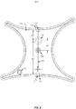
FIG. 1 illustrates a top view, front view and back view of a disposable dynamic reference for surgical navigation system, according to an embodiment of the present disclosure. -
FIG. 2 illustrates a bottom view of the disposable dynamic reference frame ofFIG. 1 utilized for a surgical navigation system, according to an embodiment of the present disclosure. -
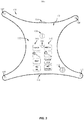
FIG. 3 illustrates a top view of the disposable dynamic reference frame highlighting a set of indicia disposed on the top surface of the device, according to one embodiment of the present disclosure. -
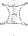
FIG. 4 illustrates a top view of the disposable dynamic reference frame highlighting the relative placement of the attachment portal and the mounting pin structure, according to an embodiment of the present disclosure. -
FIG. 5 is a perspective view of the disposable dynamic reference frame, according to one embodiment of the present disclosure. - Where the definition of terms departs from the commonly used meaning of the term, applicant intends to utilize the definitions provided below, unless specifically indicated.
- For the purposes of the present disclosure, directional terms such as "top", "bottom", "upper", "lower", "above", "below", "left", "right", "horizontal", "vertical", "upward", "downward", etc., are merely used for convenience in describing the various embodiments of the present disclosure.
- For purposes of the present disclosure, the term "asteroid" refers to a geometric design of a hypocycloid with four concave (inwardly-curved) sides which may include a variety of names, including tetracuspid, cubocycloid, and paracycle.
- For purposes of the present disclosure, the term "cusp" refers to a point made by the intersection of two curved lines or curved structures. In select disclosed embodiments, the point may be rounded
- For purposes of the present disclosure, the term "disposable" refers intended to be used once, or until no longer useful, and then discarded.
- For purposes of the present disclosure, the term "trapezium" refers to a geometric design of trapezoid with no parallel sides.
- For purposes of the present disclosure, the term "indicia" refers distinctive marks, characteristic markers or indications.
- For purposes of the present disclosure, the term "patient space" refers to the physical space within which a patience exists or is immersed. The physical space can include any portion or the entire patient or area surrounding the patient including navigation space of all physical entities such as interventional or surgical instalments or tracking makers that may interact with the patient. Generally patient space includes that area which is part of the navigable field in which an instrument or navigated portion can be tracked.
- For purposes of the present disclosure, the term "registering" refers to a process for determining the geometric relationship between an anatomic structure(s) of interest and a 3-dimensional (3D) computer image constructed, for example, from the preoperative CT scan. By way of this registration, a correct, spatial reference between the 3D image data and the position and orientation of the body part of the patient, observed by means of referencing device, can be produced.
- For purposes of the present disclosure, the term "surgical navigation" refers to computer assisted surgery (CAS) representing a surgical concept and set of methods that use computer technology for pre-surgical planning and for guiding or performing surgical interventions. CAS is also known as computer aided surgery, computer assisted intervention, image guided surgery and surgical navigation.
- For purposes of the present disclosure, the term "surgical navigation system" refers a system that allows visualization of an operative site and surgical instruments simultaneously and relates them to the patient's diagnostic images (e.g., computed tomographic (CT) scans and magnetic resonance imaging (MRI)). A surgical navigation system is used to guide the surgeon's movements during an operation. It may display the real-time position of each instrument and anatomical structure. These systems are used in orthopedics, ENT, neurology and other surgical specialties. Real-time observations occur via MRI, scanner, video camera or another imaging process. Navigation data are incorporated into the image to help the surgeon determine precise position within the organism. Medical imaging is sometimes used to plan an operation before surgery. Data integration enables the system to compare the actual position of the target object with the ideal location established during the planning phase. Such systems may be mechanical, electromagnetic or optical. The most common are optical devices, either passive or active. In the former, cameras locate specific markers such as reflective targets, particular shapes or colors. Active systems locate LEDs.
- For purposes of the present disclosure, the term "touch" or "touched" refers to action or condition of interacting with a target using any appropriate means to include bodily appendage such as fingers or any other part of the body or any other mechanical or electrical tool or device.
- For purposes of the present disclosure, the term "x-direction" refers to the direction aligned with the x-axis of a coordinate system.
- For purposes of the present disclosure, the term "y-direction" refers to the direction aligned with the y-axis of a coordinate system.
- For purposes of the present disclosure, the term "z-direction" refers to the direction aligned with the z-axis of a coordinate system. 1 inch equals 2.54 centimeters.
- The disclosure will now be described with reference to the drawing figures, in which like reference numerals refer to like parts throughout. The following detailed description is of example embodiments of the present disclosure with references to the accompanying drawings. Such description is intended to be illustrative and not limiting with respect to the scope of the present disclosure. Such embodiments are described in sufficient detail to enable one of ordinary skill in the art to practice the subject disclosure, and it will be understood that other embodiments may be practiced with some variations without departing from the scope of the subject disclosure.
- Conventional navigation systems and/or referencing devices are known, for example, from documents
DE 10 2011 054 730 A1 ,DE 698 33 881 T2 ,DE 10 2010 060 914 A1 orDE 60 2004 004 158 T2 .WO 2006/012491 discloses marker elements together with a unit carrying the marker elements - referred to as reference frames - as a single disposable unit which can be produced by injection molding. However, traditional navigation systems do not always allow for the desired positioning and orientation of the referencing device, for example, due to structural limitations in the design of its arranged configuration and/or restrictions in movement such as limited multiple ranges of motion and/or operating degrees of freedom. - Another concern may include operating and maintaining a sterile environment during surgical procedures. Medical devices, such as referencing devices must also be sterile. Within such an environment, marker elements may be removably attached, for example, by means of a standardized clip attachment to pins arranged on the referencing device. The referencing device may thus be sterilized without marker elements and new, sterile, disposable marker elements may be utilized for each use. Conventional corresponding marker elements are known, for example, from document
DE 10 2009 019 986 A1 . -
EP2179703 relates to the integration of surgical instruments and display devices and a computing unit to support image-guided surgery. In particular, it relates to a surgical instrument having a handle or holder portion and a functional portion, and a method for navigating a surgical instrument. The surgical instrument can be designed in such a way that a display device or a navigation system is provided as a separate element attachable to the instrument, which has a sterile wrapping, in particular a sterile drape or a sterile tray. Furthermore, it is conceivable that the handle or holder section and/or the functional section are formed as sterile disposable articles. In order to deduce the position and orientation of a patient (or as the case may be, the body part of a patient on which a surgical procedure is to take place), and in order to produce a correct reference to the 3D image data, it is necessary to calibrate the surgical navigation system by executing a registration step. Various reference points are thereby successively localized on the patient using a navigation apparatus and correlated with corresponding points in the 3D image data. - The registration process determines the geometric relationship between the anatomic structures of interest and the 3-dimensional (3D) computer image constructed, for example, from the preoperative CT scan. Registration involves two steps. First, the reference sensor is secured to a non-mobile structure. Then, a registration tip, for example, is used sequentially to touch pre-selected registration points (e.g., fiducial markers). Registration points may be any anatomic structures that are recognizable on the preoperative image (e.g. teeth, skin and bone). Each time a registration point is touched with the registration tip, the computer records the location of the position sensor and the reference sensor. Using, for example, at least three registration points, the computer calculates the physical position of the anatomic structure with respect to the reference sensors. The computer then uses this registration information to measure the position of the pencil relative to the preoperative CT scan. The patient's body part can be mobilized freely without the need to re-initialize the registration process, because the reference sensor is rigidly attached to the relevant structure of the patient. By way of this registration, a correct, spatial reference between the 3D image data and the position and orientation of the body part of the patient can be produced.
- In particular, in the case of surgical procedures involving the brain, it is usually not possible to simply be limited to reference points in the operating area for a necessarily precise registration, but rather it is necessary, in the vast majority of cases, to select a plurality of reference points at different locations on the body of the patient. Since for this purpose unhindered access to these locations on the body of the patient is necessary, registration must thus take place before the patient can be finally prepared for the actual surgical procedure and covered in a sterile manner in the areas outside of the operating area.
- As a practical matter, and as it pertains to the registration device itself, following a successful registration procedure necessarily means he registration device must be considered as being potentially contaminated. Thus, appropriate measures for protecting the patient must be taken before the image-guided surgical procedure using the navigation system can take place. As such, the reference frame is thus usually detached from the fixation unit, sterilized, and provided with new sterile marker elements and reconnected to the fixation unit. The fixation unit as well as the interface between the fixation unit and the reference frame must next be draped and/or otherwise covered. To achieve this, holes are typically generated in medical drapes in order to allow the reference frame or its components to protrude therethrough and to subsequently attach to the fixation unit. Additional care to secure and maintain medical drapes is also provided in order to achieve a covering considered at least sufficiently secure. From a user perspective, this approach is presented as less than desirable since, on the one hand, the effort is labor intensive and significant staff effort is required in order to provide the necessary draping and covering for operational procedure. And, on the other hand, the draping and covering is often regarding as insufficiently secure for operating procedures. This risks the sterility of the operating environment and loss of time in addressing the same.
- Accordingly, it is, therefore, an object of the present disclosure to overcome the deficiencies of the prior art to provide an improved apparatus capable of providing increased range of motion in at least multiple to an infinite amount of directions while more easily achieving and maintaining a sterile operating environment. It is a further goal of the present disclosure to provide a method and apparatus that achieves and maintains a dependable fixed position of the referencing device during operational procedures that eliminates the need to recalibrate the system.
- Embodiments of the present disclosure disclose the design and use of a disposable, single-use medical device. Turning to
device representation 100 inFIG. 1 , a disposable Dynamic Reference Frame (DRF) 101 for use in a surgical navigation system is illustrated. The dynamic reference frame comprises a track-abletop portion 102 for positioning and mounting one or moretracking marker elements 106 onto one or more mountingposts - In the disclosed embodiment,
DRF 101 has substantially an asteroid design. One disclosed design includes an external contour having an asymmetrical configuration that has been rotated by approximately 1/8 of a turn about its central normal axis (a rotation angle in the range of 22 degrees to 23 degrees) having, for example, four concave (inwardly-curved) sides 111. Select embodiments may include concave (inwardly-curved) sides 111 generally terminating with rounded comers (cusps 113) where two concave (inwardly-curved) sides meet. While four exemplary structural concave (inwardly-curved) sides 111 are shown for illustrative purposes, one skilled in the art will readily appreciate more or fewer concave (inwardly-curved) sides may be employed by disclosed embodiments. One or moretracking marker elements 106 are mounted onto one or more mountingposts exemplary structure DRF 101, one or moretracking marker elements 106 are mounted onto one or more mountingposts 107 disposed at the rounded corners (cusps 113) connecting the four concave (inwardly-curved) sides 111. - If the
dynamic reference frame 100 is used as a fiducial marker, thedynamic reference frame 100 may further comprise one or more localization divots such as, for example,divots 112 disposed at thetop portion 102 of theexemplary DRF 101, illustrated inFIG. 1 . Localization divots disposed onDRF 101 allow a pointer probe or any appropriate mechanism to determine the location ofDRF 101 relative to the patient by engaging one or more divots in a selected manner in patient space. In this way, a navigationsystem comprising DRF 101 is able to determine the position of theDRF 101 relative to the patient. Furthermore, one ormore localization divots 112 may be pointed out in the pre-acquired radiological patient image in order to register the image space with the patient space. In this way detected movement of theDRF 101 may be used to determine movement of the patient. It will be understood that the one or more localization divots may be positioned in any appropriate portion ofDRF 101 but are generally provided in an easily accessible and viewable area. Moreover, there may bemultiple divots 112 or landmarks, as discussed herein. Themultiple divots 112 may be used as fiducial markers.DRF 101 may also include a radio-opaque material to be imaged in various imaging techniques. - The location of the localization divots and mounting posts for mounting the one or more tracking marker elements are denoted by their respective x and y coordinates in the patient space. Taking mounting
post 107 as the origin point, parameters X1 and Y1 may represent the two dimensional 0,0 coordinate values, respectively, in patient space. In the exemplary embodiment ofFIG. 1 , two-dimensional coordinate values of mountingpost 108 for mountingtracking marker 106, denoted inFIG. 1 as X2 and Y2, may be selected from an applicable range approximately spanning from 4.722 to 4.732 and 0.258 to 0.268 inches, respectively. In accordance to one exemplary embodiment, parameters X2 and Y2 may be set to an optimal value of approximately 4.727 and 0.263 inches, respectively. Parameters X3 and Y3, denoted inFIG. 1 , represent the two-dimensional spatial coordinates of mountingpost 109. In the exemplary embodiment ofFIG. 1 , spatial coordinated X3 and Y3 may be selected from an applicable range approximately spanning from 0.042 to 0.052 inches and 4.248 to 4.258 inches, respectively. In accordance to one exemplary embodiment, parameters X3 and Y3 may be set to an optimal value of approximately 0.047 and 4.253 inches, respectively. Parameters X4 and Y4, denoted inFIG. 1 , represent the two-dimensional spatial coordinates of mountingpost 110. In the exemplary embodiment ofFIG. 1 , spatial coordinated X4 and Y4 may be selected from an applicable range approximately spanning from 5.041 to 5.1 inches and 4.098 to 4.108 inches, respectively. In accordance to one exemplary embodiment, parameters X4 and Y4 may be set to an optimal value of approximately 5.046 and 4.103 inches, respectively. Parameters X5 and Y5, denoted inFIG. 1 , represent the two-dimensional spatial coordinates oflocalization divot 112 disposed at thetop portion 102 of theDRF 101. In the exemplary embodiment ofFIG. 1 , spatial coordinated X5 and Y5 may be selected from an applicable range approximately spanning from 3.852 to 3.862 inches and 3.730 to 3.740 inches, respectively. In accordance to one exemplary embodiment, parameters X5 and Y5 may be set to an optimal value of approximately 3.857 and 3.735 inches, respectively. - Disclosed embodiments of the
DRF 101 may also providelocalization divots front portion 118 andback portion 120 of theDRF 101, respectively. Parameters X6 and Y6, denoted inFIG. 1 , represent the two-dimensional spatial coordinates oflocalization divot 114 disposed at thefront portion 118 ofDRF 101. In the exemplary embodiment ofFIG. 1 , spatial coordinated X6 and Y6 may be selected from an applicable range approximately spanning from 2.538 to 2.549 inches and 4.052 to 4.062 inches, respectively. In accordance to one exemplary embodiment, parameters X6 and Y6 may be set to an optimal value of approximately 2.544 and 4.057 inches, respectively. Parameters X7 and Y7, denoted inFIG. 1 , represent the two-dimensional spatial coordinates oflocalization divot 116 disposed at theback portion 120 of theDRF 101. In the exemplary embodiment ofFIG. 1 , spatial coordinated X7 and Y7 may be selected from an applicable range approximately spanning from 2.501 to 2.511 inches and 0.528 to 0.538 inches, respectively. In accordance to one exemplary embodiment, parameters X7 and Y7 may be set to an optimal value of approximately 2.506 and 0.533 inches, respectively. Parameter D1 represents the vertical distance between thetop surface 122 ofDRF 101 and center point oflocalization divot 114 disposed at thefront portion 118 of theDRF 101 and denoted by two-dimensional spatial coordinates X6 and Y6 inFIG. 1 . Parameter D2 represents the vertical distance betweenbottom surface 124 ofDRF 101 and center point oflocalization divot 116 disposed at theback portion 120 of theDRF 101 and denoted by two-dimensional spatial coordinates X7 and Y7 inFIG. 1 . - In some embodiments,
DRF 101 may comprise an attachment portal which may be used to attachDRF 101 to a connection or a positioning member that may further be affixed to a patient's body part or to a surgical instrument. InFIG. 1 ,top surface region FIG. 2 ). Attachment portal correspond to structure 126 in the back view and front view illustration of theexemplary DRF 101 inFIG. 1 . - Basic geometry dictates that at least three coordinate points corresponding to three tracking marker elements are required to define a tracking marker reference plane (two-dimensional frame). However, preferably all four of the above mentioned tracking
marker elements -
Marker elements 106 may be designed as spherical marker elements including retro-reflective marker spheres, also referred to as passive reflective markers, and are widely used in image guidance systems. Embodiments of retro-reflective marker spheres may include those used to aid registration and instrument tracking during image guided surgery procedures such as neurological procedures, spine procedures and orthopedic procedures. Embodiments may include retro-reflective marker spheres having a high coefficient of retroreflection on the external surface to provide feedback to the system/camera. Such surfaces may consist of micro glass spheres that reflect light. Depending on the medical application, different numbers and arrangements of retro-reflective marker spheres may be mounted on various types of surgical tools that may be used including that disclosed herein. Once mounted on a surgical probe, retro-reflective marker spheres provide an accurate reference point for the surgical probe in three-dimensional space. - Turning to
FIG. 2 ,device representation 200 illustrating top view of abottom portion 202 of theexemplary DRF 101 and longitudinal cross-sectional view of the front portion and backportion localization divots Localization divots recess portion FIG. 1 , represent the vertical offset of the frontportion localization divot 114, backportion localization divot 116 and mountingpin 204 relative to theattachment portal 126. Frontportion localization divot 114,attachment portal 126 and mountingpin 204 may have the same X coordinate value and thus lie at different points along a commonvertical axis 206 in the plane of DRF 10. In the exemplary embodiment, the backportion localization divot 116 is horizontally offset from thevertical axis 206 by parameter D6. In the exemplary embodiment ofFIG. 2 , parameter D3, D4, D5 and D6 may be selected from an applicable range approximately spanning from 0.766 to 0.776 inches, 2.409 to 2.419 inches, 0.682 to 0.692 inches and 0.033 to 0.043 inches respectively. In accordance to one exemplary embodiment, parameters D3, D4, D5 and D6 may be set to an optimal value of approximately 0.771, 2.414, 0.687 and 0.038 inches, respectively. - Turning to
FIG. 3 , the trackabletop portion 102 ofDRF 101 may comprise a set of one ormore indicia 302 corresponding to a plurality of functional icons, for example, on a touch screen or GUI display, wherein each functional icon represents an executable function Conventionally executable functions of an electronic device, such as an imaging controller system, may be activated through a user interface (e.g., a keyboard, mouse, touch pen, touch screen or other suitable device) thus allowing a physician or user to provide inputs to control the imaging device. An added advantage of the disclosedDRF 101 having the set of one ormore indicia 302 includes the fact thatDRF 101 is managed conveniently at the location of the patient and is maintained as a sterile device. - In the described embodiment, physical locations associated with elements of
DRF 101 may be registered to the image space locations which, in addition to the pre-acquired patient radiological image, may also comprise a plurality of functional icons graphically represented on the imaging display unit e. If the area enclosing a particular indicia 302 (e.g., disposed on thetop surface 122 ofDRF 101 in the patient space) is mapped onto the image display area associated with the corresponding graphically represented functional icons designated as part of the image space, then the executable function associated with a functional icon may be activated. For example, the executable function may be activated by invoking a software routine to execute the function associated with a functional icon. In one disclosed embodiment, this may occur in accordance with a vector of movement of the touched position on thetop surface 122 ofDRF 101, i.e., when a respective indicia is touched on the trackable top portion of the dynamic reference frame. This obviates the need to directly engage the computerized user interface which is typically disposed at a work station away from the operating table and, furthermore, may not be sterile. Examples of techniques that may be useful in spatially mapping physical objects to digital environments according to various embodiments of the present disclosure are described in U.SPatent Application No. 09/250,267 to Maurer et al U.S Patent Application No. 10/418,187 to Galloway et al U.S Patent Application No. 13/423,984 to Simon et al -
FIG. 4 illustrates an exemplary placement ofattachment portal 126 and the mountingpin 204 disposed on theback portion 202 ofDRF 101 relative toindicia 302 disposed on thefront portion 102 of theDRF 101. Parameter D7, denoted inFIG. 4 , represents vertical separation betweentop surface 402 of the frontportion localization divot 114 protruding beyond the plane ofDRF 101 and anapex point 404 of the taperedrecess portion 115 disposed in the frontportion localization divot 114. Parameter D8, denoted inFIG. 4 , represents vertical separation between top surface 405 of the backportion localization divot 116 protruding beyond the plane ofDRF 101 and anapex point 406 of the taperedrecess portion 117 disposed in the backportion localization divot 116. In the exemplary embodiment ofFIG. 4 , parameters D7 and D8 may be selected from an applicable range approximately spanning from 0.161 to 0.171 inches and 0.168 to 0.177 inches, respectively. In accordance to one exemplary embodiment, parameters D7 and D8 may be set to an optimal value of approximately 0.166 and 0.172 inches, respectively. -
FIG. 5 illustratesDRF 101 highlighting to top surface indicia, mounting post attachment locations of tracking marker elements and top portion and front portion localization divots. Accordingly, a perspective view of theexemplary DRF 101 depictstop portion 102, signifying mountingposts remote activation indicia 302 andlocalization divots 112 and 114 (backportion localization divot 116 not shown). The geometrical shape of the DRF is designed with rigidity and stability of the frame structure to allow precise alignment of tracking marker elements. This is accomplished, inter alia, by providing enough supporting structure between mountingposts DRF 101 is manufactured to a sufficient rigidity to, thereby, inhibit planar misalignment of the top surface of mountingposts - In some preferred embodiments, the plastic comprises polycarbonate, polyetherimide (PEI) or another glass filled polymer such as polyetheretherketone (PEEK). A PEEK product description includes a high performance thermoplastic, unreinforced polyetheretherketone, semi crystalline, including granules for injection molding and extrusion, standard flow, FDA food contact compliant, color natural/beige. PEEK is applicable for applications for higher strength and stiffness as well as high ductility. It is chemically resistant to aggressive environments and suitable for sterilization for medical and food contact applications. PEEK property data table is provided as follows:
Table 1 Physical Nominal Value (English) Nominal Value (SI) Test Method Density ISO 1183 Crystalline 1.30 g/cm3 1.30 g/cm3 Amorphous 1.26 g/cm3 1.26 g/cm3 Mechanical Nominal Value (English) Nominal Value (SI) Test Method Tensile Modulus (73°F (23°C)) 537000 psi 3700Mpa ISO 527-2 Tensile Stress (Yield, 73°F (23°C)) 14500 psi 100Mpa ISO 527-2 Tensile Strain (Break, 73°F (23°C)) 45% 45% ISO 527-2 Flexural Strength 73°F (23°C) (at yield) 23900psi 165Mpa 3.5% Strain, 73°F (23°C) 18100psi 125Mpa 257°F (125°C) 12300psi 85.0Mpa 347°F (175°C) 2610psi 18.0Mpa 527°F (275°C) 1890psi 13.0MPa Compressive Stress ISO 604 73°F (23°C) 18100psi 125Mpa 248°F (120°C) 10200psi 70.0Mpa Hardness Shore Hardness (Shore D, 73°F (23°C)) 85 85 ISO 868 Thermal Heat Deflection Temperature ISO 75-2/A 264 psi (1.8MPa), Unannealed 306°F 152°C Glass Transition Temperature 289°F 143°C ISO 11357-2 Melting Temperature 649°F 343°C ISO 11357-3 CLTE Flow: < 289°F (< 143°C) 0.000025 in/in/°F 0.000045 cm/cm/°C Flow: > 289°F (> 143°C) 0.000067 in/in/°F 0.00012 cm/cm/°C Transverse: < 289°F (< 143°C) 0.000031 in/in/°F 0.000055 cm/cm/°C > 289°F (> 143°C) 0.000078 in/in/°F 0.00014 cm/cm/°C Specific Heat (73°F (23°C)) 0.526 Btu/lb/°F 2200 J/kg/°C DSC Thermal Conductivity (73°F (23°C)) 2.0 Bti-in/hr/ft2/°F 0.29 W/m/K ISO 22007-4 Electrical IEC 60093 Volume Resistivity 73°F (23°C) 1.0E+16 ohm·cm 1.0E+16 ohm·cm 257°F (125°C) 1.0E+15 ohm·cm 1.0E+15 ohm·cm 437°F (225°C) 1.0E+9 ohm·cm 1.0E+9 ohm·cm IEC 60093 Electric Strength 0.00197 in (0.0500mm) 4800V/mil 190 kV/mm 0.0787 in (2.00mm) 580V/mil 23 kV/mm Dielectric Constant 73°F (23°C), 50Hz 3.00 3.00 73°F (23°C), 1kHz 3.10 3.10 257°F (125°C), 50 Hz 4.50 4.50 ISO 11443 Fill Analysis Melt Viscosity (752°F (400°C)) 350 Pa·s 350 Pa·s Injection Drying Temperature 248 to 302° F 120 to 150°C Drying Time 3.0 to 5.0 hr 3.0 to 5.0 hr - A polycarbonate product description includes a glass and carbon fiber reinforced, mineral and process additive filled structural compound material. The polycarbonate product may be offered in all infinity base resins. The polycarbonate product provides improvements in strength, stiffness, creep resistance, fatigue endurance and impact and dimensional stability. Additional properties include increased thermal heat deflection temperature or heat distortion temperature (HDTUL) and long term heat resistance. Polycarbonate property data table is provided as follows:
Table 2 Physical Nominal Value (English) Nominal Value (SI) Test Method Specific Gravity 1.34 1.34 g/cm3 ASTM D792 Specific Volume 20.7 in3/lb 0.747 cm3/g 1.26 g/cm3 Mechanical Nominal Value (English) Nominal Value (SI) Test Method Tensile Strength (Yield) 16000psi 110MPa ASTM D638 Tensile Elongation (Yield) 2.0 to 4.0% 2.0 to 4.0%i ASTM D638 Flexural Modulus 1.00E+6psi 6890 MPa ASTM D790 Flexural Strength 25000psi 172Mpa ASTM D790 Thermal Deflection Temperature Under Load ASTM D648 264 psi (1.8 MPa), Unannealed 295°F 146°C CLTE - Flow 0.000015 in/in°/F 0.000027 cm/cm°/C ASTM D696 Electrical Surface Resistivity 1.0E+17 ohm 1.0E+17 ohm ASTM D257 Injection Drying Temperature 250°F 121°C Drying Time 4.0 hr 4.0 hr Processing (Melt) Temp. 540 to 630 °F 282 to 332 ° C Mold Temperature 200°F 93.3°C - Polyetherimide material (PEI) property data table is provided as follows:
Table 3 Performance English SI Metric ASTM TEST Specific Gravity 1.27 1.27 D 792 Melt Flow Rate @337°C,/6.6kg 17.80 g/10 min 17.80 g/10 min D 1238 Molding Shrinkage 1/8 in (3.2 mm) section 0.0050-0.0070 in/in 0.50-0.70% D 955 Mechanical Tensile Strength 16000 psi 110MPa D638 Tensile Elongation >10.0% >10.0% D638 Tensile Modulus 0.52 x 10⁶ psi 3585 MPa D638 Flexural Strength 24000psi 165 MPa D 790 Flexural Modulus 0.50 x 10⁶ psi 3448 MPa D 790 General Processing for Injection Molding Injection Pressure 12000-18000psi 83-124 MPa Melt Temperature 670-750 °F 354-399 °C Mold Temperature 275-350 °F 135-177 °C Drying 4 his @ 300°F 4 hrs @ 149°C Moisture Content 0.04% 0.04% Dew Point -20 °F -20 °C - In an alternative embodiment,
DRF 101 may comprise a rigid metal. The metal may comprise aluminum, anodized aluminum and stainless steel. For 6000 Series Aluminum Alloy; Aluminum Alloy; Metal; Nonferrous Metal, a property data table is provided as follows:Table 4 Component Wt.% Component Wt.% Component Wt.% Al 95.8-98.6 Mg 0.8-1.2 Si 0.4-0.8 Cr 0.04-0.35 Mn Max 0.15 Ti Max 0.15 Cu 0.15-0.4 Other, each Max 0.05 Zn Max 0.25 Fe Max 0.7 Other total Max 0.15 Table 5 Physical Properties Metric English Density 2.7g/cc 0.0975 lb/in3 Mechanical Properties Hardness Brinell 95 95 Hardness Knoop 120 120 Hardness Rockwell A 40 40 Hardness Rockwell B 60 60 Hardness Vickers 107 107 Ultimate Tensile Strength 310Mpa 45000psi Tensile Yield Strength 276 MPA 40000psi Modulus of Elasticity 68.9GPa 10000ksi Poisson's Ratio 0.33 0.33 Fatigue Strength 96.5Mpa 14000psi Shear Modulus 26 GPa 3770ksi Shear Strength 207Mpa 30000psi Electrical Properties Electrical Resistivity 3.99e-066 ohm-cm 3.99e-066 ohm-cm -
Tracking marker element 106 may be designed as spherical marker element including a retro-reflective marker sphere, also referred to as passive reflective marker. Embodiments of retro-reflective marker spheres may include those used to aid registration and instrument tracking during image guided surgery procedures such as neurological procedures, spine procedures and orthopedic procedures. Embodiments may include a retro-reflective marker sphere having a high coefficient of retro-reflection on the external surface to provide feedback to the system/camera. Such surfaces may consist of micro glass spheres that reflect light. Depending on the medical application, different numbers and arrangements of retro-reflective marker spheres may be mounted on various types of surgical tools that may be used including that disclosed herein. Once mounted on a surgical probe, retro-reflective marker spheres provide an accuracy reference point for the surgical probe in three-dimensional space. - Embodiments of
marker element 106 may include internal structures for receiving and mating with mountingpost marker element 106 to mountingpost 107. 108, 109 and 110, but ensure thatmarker element 106 is consistently and accurately mounted such that full alignment is maintained after mounting todynamic frame reference 101. - For example, embodiments of the disclosure provide an internal stop surface of the tracking
marker elements 106 that abut thetop surfaces post DRF 101 inhibits planar misalignment oftop surfaces posts Top surfaces posts top surface 122 oftop portion 102 ofDRF 101. The internal stop surface of trackingmarker elements 106 may be mounted in abutment withtop surfaces post marker elements 106 may align on the same common horizontal plane that extends in parallel with thetop portion 102 ofDRF 101. The resultant coupling achieves precise inter-alignment of the one or moretracking marker elements 106 ontoDRF 101. - Furthermore, embodiments of the disclosure provide that the materials and material characteristics described herein are well suited for
DRF 101 to be utilized as a disposable single-use device being manufactured with trackingmarker elements 106 pre-attached to the DRF during the manufacturing process. A sterile single-use disposable DRF of the disclosure may be packaged to maintain its sterile integrity and be made available and ready for use upon request. In some embodiments, a preferred design includes a design configuration wherein the setup of the pre-attachedtracking marker elements 106 is ready for use such that the trackingmarker elements 106 are correctly aligned alongDRF 101. - It is noted that tracking
marker elements 106 may be mounted to mountingpost marker elements 106 may be pre-attached to mountingpost DRF 101,DRF 101 may be configured and employed within a surgical navigation system. Upon assembly, the unique design of the disclosed embodiment automatically and consistently aligns trackingmarker elements 106 in alignment with suitable tolerance levels of the surgical navigation system requirements. Disclosed embodiments provide a carrier body for tracking marker elements defined by the two-dimensional plane ofDRF 101 designed to correctly align and synch with the respective navigation system upon being integrated therein. The integration with the rest of the navigation system may occur, for example, via a mounting device coupled/mated withDRF 101 through theattachment portal 126. This facilitates enhancement of the setup efforts of the navigation system in a cost efficient manner and eliminates additional pre-registration and formatting procedures. - Having described the many embodiments of the present disclosure in detail, it will be apparent that modifications and variations are possible without departing from the scope of the present invention defined in the appended claims. For example, disclosed embodiments may provide certain indicia and/or colors on components of the disclosed disposable DRF device such as, but not limited to,
attachment portal 126, mountingpin 204,top portion 102,bottom portion 202,front portion 118,back portion 120, concave (inwardly-curved) sides 111, mountingposts marker elements 106. Such specific uses or applications associated with said indicia and/or colors may be employed, for example, in specific prescribed distinct surgical procedures or in certain environments or medical situations, or by specific groups of surgeons or individuals. These may include, but not limited to, for example, use in neuro and ENT surgery, spinal applications, soft/sensitive tissue applications and/or applying force applications. Additionally, other custom features may be employed and configured into the discloseddisposable DRF 101 such as pre-fashioned and custom made ergonomic grips/handles attachable toDRF 101. An example of a coloring scheme is presented as follows:Table 6 Color of Component (e.g., handle/grip) Probe Name Tip Specific Orange Blunt Pointer Pointer used for Neuro and ENT use; tip is slightly rounded (R 0,25mm). Blue Sharp Pointer Pointer used for spinal application; tip is harp, so that anatomical landmarks on bones can be acquired. Green Ball Pin Pointer Pointer for touching soft, sensitive tissue; tip with ball (R 1.5mm). Yellow Extra Strong Pointer Pointer for applying force, pointer tip with big diameter (R 2.5mm). - Furthermore, it should be appreciated that all examples in the present disclosure, while illustrating many embodiments of the present disclosure, are provided as non-limiting examples and are, therefore, not to be taken as limiting the various aspects so illustrated.
- While the present invention has been disclosed with references to certain embodiments, numerous modifications, alterations, and changes to the described embodiments are possible without departing from the scope of the present invention, as defined in the appended claims. Accordingly, it is intended that the present invention not be limited to the described embodiments, but that it has the full scope defined by the language of the following claims.
Claims (13)
- A device comprising:a rigid frame member (101) having a top portion (102);a plurality of mounts (107, 108, 109, 110) each having a top surface, wherein the plurality of mounts are disposed at prescribed locations of the top portion, wherein each mount of the plurality of mounts (107, 108, 109, 110) is configured to mount a respective tracking marker element (106) on each mount such that a centerline of each tracking marker element (106) is aligned with the top surface after mounting; andwherein the top surfaces of the plurality of mounts are configured to align on a common horizontal plane that extends in parallel with the top portion of the frame member (101); wherein indicia (302) for respective functional icons are disposed on the top portion at respective prescribed locations which can be registered to respective image space locations in an image space comprising radiological image data for a patient;wherein, optionally, a function is executed when the indicia representing the function is touched.
- The device of claim 1, wherein the mounts (107, 108, 109, 110) comprise mounting posts;wherein the one or more tracking marker elements (106) are mounted to the mounting posts such that, upon mounting, the centerline of the one or more tracking marker elements (106) align on the common horizontal plane that extends in parallel with the top portion of the frame member (101);wherein, further optionally, the tracking marker elements (106) are spherical; orwherein, further optionally, the tracking marker elements (106) are light-reflecting spherical markers.
- The device of claim 1, wherein the frame member (101) comprises an asymmetrical configuration.
- The device of claim 3, wherein the asymmetrical configuration comprises an asteroid design rotated about a central normal axis of the frame member (101);
wherein, optionally, a rotation angle is between 22 and 23 degrees. - The device of claim 4, wherein an external contour of the astroid design comprises concave (inwardly-curved) sides (111).
- The device of claim 5, wherein the astroid design has four concave (inwardly-curved) sides.
- The device of claim 5, wherein the concave (inwardly-curved) sides terminate at a cusp (113);wherein, optionally, the cusp (113) comprises rounded corners; orwherein, optionally, the mounts (107, 108, 109, 110) are disposed at each cusp (113).
- The device of claim 1, wherein the device is disposable.
- A method of manufacturing a device comprising:connecting a plurality of mounts (107, 108, 109, 110) on a top portion (102) of a frame member (101),wherein each mount of the plurality of mounts (107, 108, 109, 110) has a top surface,wherein the top surfaces of the plurality of mounts (107, 108, 109, 110) are configured to align on a common horizontal plane that extends in parallel with the top portion of the frame member (101); andmounting one or more tracking marker elements (106) on each mount and aligning a centerline of each tracking marker element (106) with the top surface; wherein the method further comprises disposing indicia (302) for respective functional icons at respective prescribed physical locations on the top portion of the frame member (101), wherein each respective prescribed physical location is registered to a respective image space location corresponding to a respective functional icon disposed on a display unit configured to display patient radiological image data;optionally comprising executing a function associated with a functional icon by touching the respective indicia for the functional icon;wherein, further optionally, executing the function associated with the functional icon comprises invoking an appropriate software routine.
- The method of claim 9, wherein the frame member (101) comprises an asymmetric configuration.
- The method of claim 10, wherein the asymmetric configuration comprises an asteroid design rotated about a central normal axis of the frame member.
- The method of claim 11, wherein a rotation angle is between 22 and 23 degrees; orwherein an external contour of the astroid design comprises concave (inwardly-curved) sides (111);wherein, optionally, the astroid design has four concave (inwardly-curved) sides; orwherein, optionally, the concave (inwardly-curved) sides terminate at a cusp (113);wherein, further optionally, the cusp (113) comprises rounded corners; orwherein, further optionally, the mounts (107, 108, 109, 110) are disposed at each cusp (113).
- The method of claim 9, wherein mounting the one or more tracking marker elements (106) on each mount and aligning a centerline of each tracking marker element (106) with the top surface forms a pre-attached marker assembly on the device.
Applications Claiming Priority (2)
| Application Number | Priority Date | Filing Date | Title |
|---|---|---|---|
| US14/807,914 US9808321B2 (en) | 2015-07-24 | 2015-07-24 | Dynamic reference frame for surgical navigation system |
| PCT/IB2015/055674 WO2017017496A1 (en) | 2015-07-24 | 2015-07-27 | Dynamic reference frame for surgical navigation system |
Publications (3)
| Publication Number | Publication Date |
|---|---|
| EP3307189A1 EP3307189A1 (en) | 2018-04-18 |
| EP3307189A4 EP3307189A4 (en) | 2018-07-04 |
| EP3307189B1 true EP3307189B1 (en) | 2021-09-01 |
Family
ID=57836431
Family Applications (1)
| Application Number | Title | Priority Date | Filing Date |
|---|---|---|---|
| EP15899531.6A Not-in-force EP3307189B1 (en) | 2015-07-24 | 2015-07-27 | Dynamic reference frame for surgical navigation system |
Country Status (4)
| Country | Link |
|---|---|
| US (2) | US9808321B2 (en) |
| EP (1) | EP3307189B1 (en) |
| CA (1) | CA2986670A1 (en) |
| WO (1) | WO2017017496A1 (en) |
Families Citing this family (25)
| Publication number | Priority date | Publication date | Assignee | Title |
|---|---|---|---|---|
| US9913577B2 (en) | 2010-09-28 | 2018-03-13 | Obp Medical Corporation | Speculum |
| US10420538B2 (en) | 2015-02-05 | 2019-09-24 | Obp Medical Corporation | Illuminated surgical retractor |
| US20160310121A1 (en) * | 2015-02-05 | 2016-10-27 | Obp Medical | Illuminated Surgical Retractor |
| US9867602B2 (en) | 2015-02-05 | 2018-01-16 | Obp Medical Corporation | Illuminated surgical retractor |
| US10952712B2 (en) | 2015-06-03 | 2021-03-23 | Obp Medical Corporation | Retractor |
| US10881387B2 (en) | 2015-06-03 | 2021-01-05 | Obp Medical Corporation | Retractor |
| US10939899B2 (en) | 2015-06-03 | 2021-03-09 | Obp Medical Corporation | End cap assembly for retractor and other medical devices |
| US10722621B2 (en) | 2016-07-11 | 2020-07-28 | Obp Medical Corporation | Illuminated suction device |
| US10687793B2 (en) | 2017-07-18 | 2020-06-23 | Obp Medical Corporation | Minimally invasive no touch (MINT) procedure for harvesting the great saphenous vein (GSV) and venous hydrodissector and retractor for use during the MINT procedure |
| US10278572B1 (en) | 2017-10-19 | 2019-05-07 | Obp Medical Corporation | Speculum |
| EP3755234B1 (en) | 2018-02-20 | 2025-07-09 | CooperSurgical, Inc. | Illuminated medical devices |
| US10799229B2 (en) | 2018-02-20 | 2020-10-13 | Obp Medical Corporation | Illuminated medical devices |
| USD911521S1 (en) | 2019-02-19 | 2021-02-23 | Obp Medical Corporation | Handle for medical devices including surgical retractors |
| USD904607S1 (en) | 2019-05-07 | 2020-12-08 | Obp Medical Corporation | Nasal retractor |
| US10959609B1 (en) | 2020-01-31 | 2021-03-30 | Obp Medical Corporation | Illuminated suction device |
| US10966702B1 (en) | 2020-02-25 | 2021-04-06 | Obp Medical Corporation | Illuminated dual-blade retractor |
| EP4274505A1 (en) | 2021-01-06 | 2023-11-15 | Mako Surgical Corp. | Tracker for a navigation system |
| US12295678B2 (en) | 2021-02-08 | 2025-05-13 | Medtronic Navigation, Inc. | Systems and methods for intraoperative re-registration |
| DE102022115510B4 (en) | 2021-06-24 | 2023-07-06 | Northern Digital Inc. | RETROREFLECTIVE MARKER |
| CN116758144B (en) * | 2023-06-06 | 2025-12-23 | 武汉联影智融医疗科技有限公司 | Method, device, equipment and storage medium for acquiring spherical center coordinates of reflective sphere |
| US12271009B2 (en) | 2023-07-07 | 2025-04-08 | Northern Digital Inc. | Retro-reflective marker with uniformly distributed microelements |
| US12318080B2 (en) | 2023-07-21 | 2025-06-03 | Coopersurgical, Inc. | Illuminated surgical retractor capable of hand-held operation and of being mounted to a fixed frame |
| USD1120320S1 (en) | 2023-08-18 | 2026-03-24 | Mako Surgical Corp. | Surgical tracker |
| USD1117755S1 (en) | 2023-08-18 | 2026-03-10 | Mako Surgical Corp. | Surgical tracker |
| USD1121826S1 (en) | 2023-08-18 | 2026-04-07 | Stryker European Operations Limited | Surgical tracker |
Family Cites Families (22)
| Publication number | Priority date | Publication date | Assignee | Title |
|---|---|---|---|---|
| US6405072B1 (en) | 1991-01-28 | 2002-06-11 | Sherwood Services Ag | Apparatus and method for determining a location of an anatomical target with reference to a medical apparatus |
| US6273896B1 (en) * | 1998-04-21 | 2001-08-14 | Neutar, Llc | Removable frames for stereotactic localization |
| US6560354B1 (en) | 1999-02-16 | 2003-05-06 | University Of Rochester | Apparatus and method for registration of images to physical space using a weighted combination of points and surfaces |
| US20010034530A1 (en) * | 2000-01-27 | 2001-10-25 | Malackowski Donald W. | Surgery system |
| US6725080B2 (en) | 2000-03-01 | 2004-04-20 | Surgical Navigation Technologies, Inc. | Multiple cannula image guided tool for image guided procedures |
| US6584339B2 (en) | 2001-06-27 | 2003-06-24 | Vanderbilt University | Method and apparatus for collecting and processing physical space data for use while performing image-guided surgery |
| US7720522B2 (en) | 2003-02-25 | 2010-05-18 | Medtronic, Inc. | Fiducial marker devices, tools, and methods |
| US20040116802A1 (en) | 2002-10-05 | 2004-06-17 | Jessop Precision Products, Inc. | Medical imaging marker |
| GB0320787D0 (en) | 2003-09-05 | 2003-10-08 | Depuy Int Ltd | Flexible image guided surgery marker |
| US7764985B2 (en) | 2003-10-20 | 2010-07-27 | Smith & Nephew, Inc. | Surgical navigation system component fault interfaces and related processes |
| US7840256B2 (en) | 2005-06-27 | 2010-11-23 | Biomet Manufacturing Corporation | Image guided tracking array and method |
| US8073526B2 (en) * | 2007-02-16 | 2011-12-06 | Sunnybrook Health Sciences Centre | Method and system for computerized drawing and writing during functional magnetic resonance imaging |
| US8150494B2 (en) | 2007-03-29 | 2012-04-03 | Medtronic Navigation, Inc. | Apparatus for registering a physical space to image space |
| WO2010030809A1 (en) * | 2008-09-10 | 2010-03-18 | Orthalign, Inc | Hip surgery systems and methods |
| EP2455038B1 (en) * | 2008-10-21 | 2015-04-01 | Brainlab AG | Integration of surgical instrument and display device for supporting image led surgery |
| EP2578178A3 (en) * | 2009-04-28 | 2014-12-31 | Brainlab AG | Method for controlling software for supporting treatment |
| DE102009019986B8 (en) | 2009-05-06 | 2013-08-01 | Ilumark Gmbh | Retro reflective marker |
| US8737708B2 (en) | 2009-05-13 | 2014-05-27 | Medtronic Navigation, Inc. | System and method for automatic registration between an image and a subject |
| WO2011156701A2 (en) * | 2010-06-10 | 2011-12-15 | C2C Development, Llc | Trajectory guide, access port, and fiducial marker alignment |
| DE102010060914A1 (en) | 2010-11-30 | 2012-05-31 | Aesculap Ag | Surgical marker element for surgical correlation unit of surgical navigation system, has luminescent material that is excited from low energy state to high energy state by producing electromagnetic radiation or electron bombardment |
| DE102011054730A1 (en) | 2011-10-21 | 2013-04-25 | Aesculap Ag | Surgical navigation system has detection unit for detecting position or orientation of marker unit equipped with surgical referencing unit in space, where detection unit has two detectors arranged movably relative to each other |
| US20150133945A1 (en) * | 2012-05-02 | 2015-05-14 | Stryker Global Technology Center | Handheld tracking system and devices for aligning implant systems during surgery |
-
2015
- 2015-07-24 US US14/807,914 patent/US9808321B2/en active Active
- 2015-07-27 WO PCT/IB2015/055674 patent/WO2017017496A1/en not_active Ceased
- 2015-07-27 CA CA2986670A patent/CA2986670A1/en not_active Abandoned
- 2015-07-27 EP EP15899531.6A patent/EP3307189B1/en not_active Not-in-force
-
2016
- 2016-07-21 US US15/215,919 patent/US20170020622A1/en not_active Abandoned
Also Published As
| Publication number | Publication date |
|---|---|
| CA2986670A1 (en) | 2017-02-02 |
| US20170020622A1 (en) | 2017-01-26 |
| WO2017017496A1 (en) | 2017-02-02 |
| US9808321B2 (en) | 2017-11-07 |
| US20170020621A1 (en) | 2017-01-26 |
| EP3307189A4 (en) | 2018-07-04 |
| EP3307189A1 (en) | 2018-04-18 |
Similar Documents
| Publication | Publication Date | Title |
|---|---|---|
| US9808321B2 (en) | Dynamic reference frame for surgical navigation system | |
| US12167940B2 (en) | Methods and systems for display of patient data in computer-assisted surgery | |
| US20210393160A1 (en) | System and method for displaying anatomy and devices on a movable display | |
| US20200229888A1 (en) | System and method for measuring depth of instrumentation | |
| EP3212104B1 (en) | Hybrid navigation system for surgical interventions | |
| EP3216416B1 (en) | Reference device for surgical navigation system | |
| EP3360502A2 (en) | Robotic navigation of robotic surgical systems | |
| EP3216414B1 (en) | Medical device for surgical navigation | |
| JP2022553385A (en) | ENT treatment visualization system and method | |
| CN110876643A (en) | Medical surgery navigation system and method | |
| CN111417352A (en) | Method and system for setting trajectories and target locations for image-guided surgery | |
| Caversaccio et al. | Computer assistance for intraoperative navigation in ENT surgery | |
| Mert et al. | Advanced cranial navigation | |
| EP3695412A1 (en) | Medical guidance system and method using localized plane | |
| EP2124737A2 (en) | System and method for registration of localization and imaging systems for navigational control of medical devices | |
| EP3318213A1 (en) | System and method for measuring depth of instrumentation | |
| Finlay et al. | PathFinder image guided robot for neurosurgery | |
| Hummel et al. | Laboratory assessment of a miniature electromagnetic tracker | |
| HK1257573A1 (en) | Robotic navigation of robotic surgical systems |
Legal Events
| Date | Code | Title | Description |
|---|---|---|---|
| STAA | Information on the status of an ep patent application or granted ep patent |
Free format text: STATUS: THE INTERNATIONAL PUBLICATION HAS BEEN MADE |
|
| PUAI | Public reference made under article 153(3) epc to a published international application that has entered the european phase |
Free format text: ORIGINAL CODE: 0009012 |
|
| STAA | Information on the status of an ep patent application or granted ep patent |
Free format text: STATUS: REQUEST FOR EXAMINATION WAS MADE |
|
| 17P | Request for examination filed |
Effective date: 20180111 |
|
| AK | Designated contracting states |
Kind code of ref document: A1 Designated state(s): AL AT BE BG CH CY CZ DE DK EE ES FI FR GB GR HR HU IE IS IT LI LT LU LV MC MK MT NL NO PL PT RO RS SE SI SK SM TR |
|
| AX | Request for extension of the european patent |
Extension state: BA ME |
|
| A4 | Supplementary search report drawn up and despatched |
Effective date: 20180606 |
|
| RIC1 | Information provided on ipc code assigned before grant |
Ipc: A61B 90/10 20160101ALI20180531BHEP Ipc: A61B 34/20 20160101AFI20180531BHEP Ipc: A61B 17/00 20060101ALN20180531BHEP Ipc: A61B 90/00 20160101ALN20180531BHEP Ipc: A61B 34/00 20160101ALN20180531BHEP |
|
| DAV | Request for validation of the european patent (deleted) | ||
| DAX | Request for extension of the european patent (deleted) | ||
| STAA | Information on the status of an ep patent application or granted ep patent |
Free format text: STATUS: EXAMINATION IS IN PROGRESS |
|
| 17Q | First examination report despatched |
Effective date: 20200305 |
|
| REG | Reference to a national code |
Ref country code: DE Ref legal event code: R079 Ref document number: 602015072987 Country of ref document: DE Free format text: PREVIOUS MAIN CLASS: A61B0034000000 Ipc: A61B0034200000 |
|
| GRAP | Despatch of communication of intention to grant a patent |
Free format text: ORIGINAL CODE: EPIDOSNIGR1 |
|
| STAA | Information on the status of an ep patent application or granted ep patent |
Free format text: STATUS: GRANT OF PATENT IS INTENDED |
|
| RIC1 | Information provided on ipc code assigned before grant |
Ipc: A61B 90/00 20160101ALN20210312BHEP Ipc: A61B 34/00 20160101ALN20210312BHEP Ipc: A61B 17/00 20060101ALN20210312BHEP Ipc: A61B 90/10 20160101ALI20210312BHEP Ipc: A61B 34/20 20160101AFI20210312BHEP |
|
| RIC1 | Information provided on ipc code assigned before grant |
Ipc: A61B 90/00 20160101ALN20210325BHEP Ipc: A61B 34/00 20160101ALN20210325BHEP Ipc: A61B 17/00 20060101ALN20210325BHEP Ipc: A61B 90/10 20160101ALI20210325BHEP Ipc: A61B 34/20 20160101AFI20210325BHEP |
|
| INTG | Intention to grant announced |
Effective date: 20210409 |
|
| GRAS | Grant fee paid |
Free format text: ORIGINAL CODE: EPIDOSNIGR3 |
|
| GRAA | (expected) grant |
Free format text: ORIGINAL CODE: 0009210 |
|
| STAA | Information on the status of an ep patent application or granted ep patent |
Free format text: STATUS: THE PATENT HAS BEEN GRANTED |
|
| AK | Designated contracting states |
Kind code of ref document: B1 Designated state(s): AL AT BE BG CH CY CZ DE DK EE ES FI FR GB GR HR HU IE IS IT LI LT LU LV MC MK MT NL NO PL PT RO RS SE SI SK SM TR |
|
| REG | Reference to a national code |
Ref country code: GB Ref legal event code: FG4D |
|
| REG | Reference to a national code |
Ref country code: CH Ref legal event code: EP Ref country code: AT Ref legal event code: REF Ref document number: 1425383 Country of ref document: AT Kind code of ref document: T Effective date: 20210915 |
|
| REG | Reference to a national code |
Ref country code: DE Ref legal event code: R096 Ref document number: 602015072987 Country of ref document: DE |
|
| REG | Reference to a national code |
Ref country code: IE Ref legal event code: FG4D |
|
| REG | Reference to a national code |
Ref country code: LT Ref legal event code: MG9D |
|
| REG | Reference to a national code |
Ref country code: NL Ref legal event code: MP Effective date: 20210901 |
|
| PG25 | Lapsed in a contracting state [announced via postgrant information from national office to epo] |
Ref country code: SE Free format text: LAPSE BECAUSE OF FAILURE TO SUBMIT A TRANSLATION OF THE DESCRIPTION OR TO PAY THE FEE WITHIN THE PRESCRIBED TIME-LIMIT Effective date: 20210901 Ref country code: RS Free format text: LAPSE BECAUSE OF FAILURE TO SUBMIT A TRANSLATION OF THE DESCRIPTION OR TO PAY THE FEE WITHIN THE PRESCRIBED TIME-LIMIT Effective date: 20210901 Ref country code: HR Free format text: LAPSE BECAUSE OF FAILURE TO SUBMIT A TRANSLATION OF THE DESCRIPTION OR TO PAY THE FEE WITHIN THE PRESCRIBED TIME-LIMIT Effective date: 20210901 Ref country code: BG Free format text: LAPSE BECAUSE OF FAILURE TO SUBMIT A TRANSLATION OF THE DESCRIPTION OR TO PAY THE FEE WITHIN THE PRESCRIBED TIME-LIMIT Effective date: 20211201 Ref country code: LT Free format text: LAPSE BECAUSE OF FAILURE TO SUBMIT A TRANSLATION OF THE DESCRIPTION OR TO PAY THE FEE WITHIN THE PRESCRIBED TIME-LIMIT Effective date: 20210901 Ref country code: NO Free format text: LAPSE BECAUSE OF FAILURE TO SUBMIT A TRANSLATION OF THE DESCRIPTION OR TO PAY THE FEE WITHIN THE PRESCRIBED TIME-LIMIT Effective date: 20211201 Ref country code: FI Free format text: LAPSE BECAUSE OF FAILURE TO SUBMIT A TRANSLATION OF THE DESCRIPTION OR TO PAY THE FEE WITHIN THE PRESCRIBED TIME-LIMIT Effective date: 20210901 Ref country code: ES Free format text: LAPSE BECAUSE OF FAILURE TO SUBMIT A TRANSLATION OF THE DESCRIPTION OR TO PAY THE FEE WITHIN THE PRESCRIBED TIME-LIMIT Effective date: 20210901 |
|
| REG | Reference to a national code |
Ref country code: AT Ref legal event code: MK05 Ref document number: 1425383 Country of ref document: AT Kind code of ref document: T Effective date: 20210901 |
|
| PG25 | Lapsed in a contracting state [announced via postgrant information from national office to epo] |
Ref country code: PL Free format text: LAPSE BECAUSE OF FAILURE TO SUBMIT A TRANSLATION OF THE DESCRIPTION OR TO PAY THE FEE WITHIN THE PRESCRIBED TIME-LIMIT Effective date: 20210901 Ref country code: LV Free format text: LAPSE BECAUSE OF FAILURE TO SUBMIT A TRANSLATION OF THE DESCRIPTION OR TO PAY THE FEE WITHIN THE PRESCRIBED TIME-LIMIT Effective date: 20210901 Ref country code: GR Free format text: LAPSE BECAUSE OF FAILURE TO SUBMIT A TRANSLATION OF THE DESCRIPTION OR TO PAY THE FEE WITHIN THE PRESCRIBED TIME-LIMIT Effective date: 20211202 |
|
| PG25 | Lapsed in a contracting state [announced via postgrant information from national office to epo] |
Ref country code: AT Free format text: LAPSE BECAUSE OF FAILURE TO SUBMIT A TRANSLATION OF THE DESCRIPTION OR TO PAY THE FEE WITHIN THE PRESCRIBED TIME-LIMIT Effective date: 20210901 |
|
| PG25 | Lapsed in a contracting state [announced via postgrant information from national office to epo] |
Ref country code: IS Free format text: LAPSE BECAUSE OF FAILURE TO SUBMIT A TRANSLATION OF THE DESCRIPTION OR TO PAY THE FEE WITHIN THE PRESCRIBED TIME-LIMIT Effective date: 20220101 Ref country code: SM Free format text: LAPSE BECAUSE OF FAILURE TO SUBMIT A TRANSLATION OF THE DESCRIPTION OR TO PAY THE FEE WITHIN THE PRESCRIBED TIME-LIMIT Effective date: 20210901 Ref country code: SK Free format text: LAPSE BECAUSE OF FAILURE TO SUBMIT A TRANSLATION OF THE DESCRIPTION OR TO PAY THE FEE WITHIN THE PRESCRIBED TIME-LIMIT Effective date: 20210901 Ref country code: RO Free format text: LAPSE BECAUSE OF FAILURE TO SUBMIT A TRANSLATION OF THE DESCRIPTION OR TO PAY THE FEE WITHIN THE PRESCRIBED TIME-LIMIT Effective date: 20210901 Ref country code: PT Free format text: LAPSE BECAUSE OF FAILURE TO SUBMIT A TRANSLATION OF THE DESCRIPTION OR TO PAY THE FEE WITHIN THE PRESCRIBED TIME-LIMIT Effective date: 20220103 Ref country code: NL Free format text: LAPSE BECAUSE OF FAILURE TO SUBMIT A TRANSLATION OF THE DESCRIPTION OR TO PAY THE FEE WITHIN THE PRESCRIBED TIME-LIMIT Effective date: 20210901 Ref country code: EE Free format text: LAPSE BECAUSE OF FAILURE TO SUBMIT A TRANSLATION OF THE DESCRIPTION OR TO PAY THE FEE WITHIN THE PRESCRIBED TIME-LIMIT Effective date: 20210901 Ref country code: CZ Free format text: LAPSE BECAUSE OF FAILURE TO SUBMIT A TRANSLATION OF THE DESCRIPTION OR TO PAY THE FEE WITHIN THE PRESCRIBED TIME-LIMIT Effective date: 20210901 Ref country code: AL Free format text: LAPSE BECAUSE OF FAILURE TO SUBMIT A TRANSLATION OF THE DESCRIPTION OR TO PAY THE FEE WITHIN THE PRESCRIBED TIME-LIMIT Effective date: 20210901 |
|
| REG | Reference to a national code |
Ref country code: DE Ref legal event code: R097 Ref document number: 602015072987 Country of ref document: DE |
|
| PLBE | No opposition filed within time limit |
Free format text: ORIGINAL CODE: 0009261 |
|
| STAA | Information on the status of an ep patent application or granted ep patent |
Free format text: STATUS: NO OPPOSITION FILED WITHIN TIME LIMIT |
|
| PG25 | Lapsed in a contracting state [announced via postgrant information from national office to epo] |
Ref country code: IT Free format text: LAPSE BECAUSE OF FAILURE TO SUBMIT A TRANSLATION OF THE DESCRIPTION OR TO PAY THE FEE WITHIN THE PRESCRIBED TIME-LIMIT Effective date: 20210901 Ref country code: DK Free format text: LAPSE BECAUSE OF FAILURE TO SUBMIT A TRANSLATION OF THE DESCRIPTION OR TO PAY THE FEE WITHIN THE PRESCRIBED TIME-LIMIT Effective date: 20210901 |
|
| 26N | No opposition filed |
Effective date: 20220602 |
|
| PG25 | Lapsed in a contracting state [announced via postgrant information from national office to epo] |
Ref country code: SI Free format text: LAPSE BECAUSE OF FAILURE TO SUBMIT A TRANSLATION OF THE DESCRIPTION OR TO PAY THE FEE WITHIN THE PRESCRIBED TIME-LIMIT Effective date: 20210901 |
|
| REG | Reference to a national code |
Ref country code: DE Ref legal event code: R119 Ref document number: 602015072987 Country of ref document: DE |
|
| PG25 | Lapsed in a contracting state [announced via postgrant information from national office to epo] |
Ref country code: MC Free format text: LAPSE BECAUSE OF FAILURE TO SUBMIT A TRANSLATION OF THE DESCRIPTION OR TO PAY THE FEE WITHIN THE PRESCRIBED TIME-LIMIT Effective date: 20210901 |
|
| REG | Reference to a national code |
Ref country code: CH Ref legal event code: PL |
|
| GBPC | Gb: european patent ceased through non-payment of renewal fee |
Effective date: 20220727 |
|
| REG | Reference to a national code |
Ref country code: BE Ref legal event code: MM Effective date: 20220731 |
|
| PG25 | Lapsed in a contracting state [announced via postgrant information from national office to epo] |
Ref country code: LU Free format text: LAPSE BECAUSE OF NON-PAYMENT OF DUE FEES Effective date: 20220727 Ref country code: LI Free format text: LAPSE BECAUSE OF NON-PAYMENT OF DUE FEES Effective date: 20220731 Ref country code: FR Free format text: LAPSE BECAUSE OF NON-PAYMENT OF DUE FEES Effective date: 20220731 Ref country code: CH Free format text: LAPSE BECAUSE OF NON-PAYMENT OF DUE FEES Effective date: 20220731 |
|
| PG25 | Lapsed in a contracting state [announced via postgrant information from national office to epo] |
Ref country code: DE Free format text: LAPSE BECAUSE OF NON-PAYMENT OF DUE FEES Effective date: 20230201 Ref country code: BE Free format text: LAPSE BECAUSE OF NON-PAYMENT OF DUE FEES Effective date: 20220731 Ref country code: GB Free format text: LAPSE BECAUSE OF NON-PAYMENT OF DUE FEES Effective date: 20220727 |
|
| P01 | Opt-out of the competence of the unified patent court (upc) registered |
Effective date: 20230517 |
|
| PG25 | Lapsed in a contracting state [announced via postgrant information from national office to epo] |
Ref country code: IE Free format text: LAPSE BECAUSE OF NON-PAYMENT OF DUE FEES Effective date: 20220727 |
|
| PG25 | Lapsed in a contracting state [announced via postgrant information from national office to epo] |
Ref country code: HU Free format text: LAPSE BECAUSE OF FAILURE TO SUBMIT A TRANSLATION OF THE DESCRIPTION OR TO PAY THE FEE WITHIN THE PRESCRIBED TIME-LIMIT; INVALID AB INITIO Effective date: 20150727 |
|
| PG25 | Lapsed in a contracting state [announced via postgrant information from national office to epo] |
Ref country code: MK Free format text: LAPSE BECAUSE OF FAILURE TO SUBMIT A TRANSLATION OF THE DESCRIPTION OR TO PAY THE FEE WITHIN THE PRESCRIBED TIME-LIMIT Effective date: 20210901 Ref country code: CY Free format text: LAPSE BECAUSE OF FAILURE TO SUBMIT A TRANSLATION OF THE DESCRIPTION OR TO PAY THE FEE WITHIN THE PRESCRIBED TIME-LIMIT Effective date: 20210901 |
|
| PG25 | Lapsed in a contracting state [announced via postgrant information from national office to epo] |
Ref country code: MT Free format text: LAPSE BECAUSE OF FAILURE TO SUBMIT A TRANSLATION OF THE DESCRIPTION OR TO PAY THE FEE WITHIN THE PRESCRIBED TIME-LIMIT Effective date: 20210901 |
|
| PG25 | Lapsed in a contracting state [announced via postgrant information from national office to epo] |
Ref country code: TR Free format text: LAPSE BECAUSE OF FAILURE TO SUBMIT A TRANSLATION OF THE DESCRIPTION OR TO PAY THE FEE WITHIN THE PRESCRIBED TIME-LIMIT Effective date: 20210901 |