EP3306977B1 - Verfahren und vorrichtung zur übertragung der anzeige der verfügbarkeit von wlan-offloading - Google Patents
Verfahren und vorrichtung zur übertragung der anzeige der verfügbarkeit von wlan-offloading Download PDFInfo
- Publication number
- EP3306977B1 EP3306977B1 EP16803750.5A EP16803750A EP3306977B1 EP 3306977 B1 EP3306977 B1 EP 3306977B1 EP 16803750 A EP16803750 A EP 16803750A EP 3306977 B1 EP3306977 B1 EP 3306977B1
- Authority
- EP
- European Patent Office
- Prior art keywords
- wlan
- cell
- offloading
- traffic
- network
- Prior art date
- Legal status (The legal status is an assumption and is not a legal conclusion. Google has not performed a legal analysis and makes no representation as to the accuracy of the status listed.)
- Active
Links
- 238000000034 method Methods 0.000 title claims description 89
- 238000004891 communication Methods 0.000 claims description 22
- 230000004044 response Effects 0.000 claims description 11
- 238000005259 measurement Methods 0.000 description 81
- 230000002776 aggregation Effects 0.000 description 32
- 238000004220 aggregation Methods 0.000 description 32
- 230000006870 function Effects 0.000 description 31
- 230000008569 process Effects 0.000 description 27
- 230000005540 biological transmission Effects 0.000 description 16
- 238000007726 management method Methods 0.000 description 15
- 230000011664 signaling Effects 0.000 description 11
- 238000005516 engineering process Methods 0.000 description 8
- 238000010187 selection method Methods 0.000 description 8
- 238000012546 transfer Methods 0.000 description 8
- 230000008859 change Effects 0.000 description 6
- 238000010586 diagram Methods 0.000 description 4
- 238000011156 evaluation Methods 0.000 description 4
- 230000006835 compression Effects 0.000 description 3
- 238000007906 compression Methods 0.000 description 3
- GVVPGTZRZFNKDS-JXMROGBWSA-N geranyl diphosphate Chemical compound CC(C)=CCC\C(C)=C\CO[P@](O)(=O)OP(O)(O)=O GVVPGTZRZFNKDS-JXMROGBWSA-N 0.000 description 3
- 230000007774 longterm Effects 0.000 description 3
- 238000013468 resource allocation Methods 0.000 description 3
- 108091005487 SCARB1 Proteins 0.000 description 2
- 102100037118 Scavenger receptor class B member 1 Human genes 0.000 description 2
- 230000006978 adaptation Effects 0.000 description 2
- 238000007796 conventional method Methods 0.000 description 2
- 238000001914 filtration Methods 0.000 description 2
- 238000007689 inspection Methods 0.000 description 2
- 238000013507 mapping Methods 0.000 description 2
- 238000010295 mobile communication Methods 0.000 description 2
- 238000012545 processing Methods 0.000 description 2
- 230000007704 transition Effects 0.000 description 2
- 230000001960 triggered effect Effects 0.000 description 2
- 101100161473 Arabidopsis thaliana ABCB25 gene Proteins 0.000 description 1
- 101100150273 Caenorhabditis elegans srb-1 gene Proteins 0.000 description 1
- 101100096893 Mus musculus Sult2a1 gene Proteins 0.000 description 1
- 101150081243 STA1 gene Proteins 0.000 description 1
- 230000004913 activation Effects 0.000 description 1
- 230000008878 coupling Effects 0.000 description 1
- 238000010168 coupling process Methods 0.000 description 1
- 238000005859 coupling reaction Methods 0.000 description 1
- 238000012854 evaluation process Methods 0.000 description 1
- 230000008054 signal transmission Effects 0.000 description 1
- 230000001360 synchronised effect Effects 0.000 description 1
- 230000002123 temporal effect Effects 0.000 description 1
- 238000012384 transportation and delivery Methods 0.000 description 1
Images


Classifications
-
- H—ELECTRICITY
- H04—ELECTRIC COMMUNICATION TECHNIQUE
- H04W—WIRELESS COMMUNICATION NETWORKS
- H04W36/00—Hand-off or reselection arrangements
- H04W36/16—Performing reselection for specific purposes
- H04W36/22—Performing reselection for specific purposes for handling the traffic
-
- H—ELECTRICITY
- H04—ELECTRIC COMMUNICATION TECHNIQUE
- H04W—WIRELESS COMMUNICATION NETWORKS
- H04W24/00—Supervisory, monitoring or testing arrangements
- H04W24/10—Scheduling measurement reports ; Arrangements for measurement reports
-
- H—ELECTRICITY
- H04—ELECTRIC COMMUNICATION TECHNIQUE
- H04W—WIRELESS COMMUNICATION NETWORKS
- H04W28/00—Network traffic management; Network resource management
- H04W28/02—Traffic management, e.g. flow control or congestion control
-
- H—ELECTRICITY
- H04—ELECTRIC COMMUNICATION TECHNIQUE
- H04W—WIRELESS COMMUNICATION NETWORKS
- H04W28/00—Network traffic management; Network resource management
- H04W28/02—Traffic management, e.g. flow control or congestion control
- H04W28/0247—Traffic management, e.g. flow control or congestion control based on conditions of the access network or the infrastructure network
-
- H—ELECTRICITY
- H04—ELECTRIC COMMUNICATION TECHNIQUE
- H04W—WIRELESS COMMUNICATION NETWORKS
- H04W88/00—Devices specially adapted for wireless communication networks, e.g. terminals, base stations or access point devices
- H04W88/02—Terminal devices
- H04W88/06—Terminal devices adapted for operation in multiple networks or having at least two operational modes, e.g. multi-mode terminals
-
- H—ELECTRICITY
- H04—ELECTRIC COMMUNICATION TECHNIQUE
- H04W—WIRELESS COMMUNICATION NETWORKS
- H04W36/00—Hand-off or reselection arrangements
- H04W36/14—Reselecting a network or an air interface
-
- H—ELECTRICITY
- H04—ELECTRIC COMMUNICATION TECHNIQUE
- H04W—WIRELESS COMMUNICATION NETWORKS
- H04W36/00—Hand-off or reselection arrangements
- H04W36/14—Reselecting a network or an air interface
- H04W36/144—Reselecting a network or an air interface over a different radio air interface technology
- H04W36/1446—Reselecting a network or an air interface over a different radio air interface technology wherein at least one of the networks is unlicensed
-
- H—ELECTRICITY
- H04—ELECTRIC COMMUNICATION TECHNIQUE
- H04W—WIRELESS COMMUNICATION NETWORKS
- H04W84/00—Network topologies
- H04W84/02—Hierarchically pre-organised networks, e.g. paging networks, cellular networks, WLAN [Wireless Local Area Network] or WLL [Wireless Local Loop]
- H04W84/10—Small scale networks; Flat hierarchical networks
- H04W84/12—WLAN [Wireless Local Area Networks]
Definitions
- the present invention relates to a wireless communication system, and more particularly, to a method of transmitting a wireless local area network (WLAN) offloading availability indication by a UE in the wireless communication system, and a device supporting the method.
- WLAN wireless local area network
- 3GPP (3rd Generation Partnership Project) LTE Long Term Evolution (Long Term Evolution) that is an advancement of UMTS (Universal Mobile Telecommunication System) is being introduced with 3GPP release 8.
- 3GPP LTE OFDMA (orthogonal frequency division multiple access) is used for downlink, and SC-FDMA (single carrier-frequency division multiple access) is used for uplink.
- the 3GPP LTE adopts MIMO (multiple input multiple output) having maximum four antennas.
- 3GPP LTE-A LTE-Advanced
- a wireless communication system may provide a service to a UE through a plurality of access networks.
- the UE may receive a service from a 3GPP access network such as a mobile wireless communication system. Further, the UE may receive the service from a non-3GPP access network such as WiMAX (Worldwide Interoperability for Microwave Access) or a WLAN (Wireless Local Area Network).
- a 3GPP access network such as a mobile wireless communication system.
- a non-3GPP access network such as WiMAX (Worldwide Interoperability for Microwave Access) or a WLAN (Wireless Local Area Network).
- the UE may establish connection with a 3GPP access network to receive the service. Meanwhile, when traffic overload is generated in a 3GPP access network, if traffic to be processed by the UE is processed by another access network, that is, the non-3GPP access network, the whole efficiency of the network may be improved.
- changeable process of the traffic through the 3GPP access network and/or the non-GPP access network refers to traffic steering so that the traffic is changeably processed through a 3GPP access network and/or a non-GPP access network.
- a policy for interworking of the 3GPP access network and/or the non-GPP access network such as ANDSF (Access Network Discovery and Selection Functions) may be configured in the UE.
- the above policy is managed independently from an interworking policy configured by the network.
- the 3GPP Draft No. R2-132328, entitled “UE Indication on WLAN availability”, discusses options for a UE to provide WLAN settings and WLAN availability to the network.
- International application publication No. WO 2014/000808 A1 discusses the offloading of user plane packets from a macro base station to an access point.
- a UE does not have long term evolution (LTE) traffic which can be offloaded to a wireless local area network (WLAN)
- the UE may not be able to perform an LTE/WLAN aggregation configuration or LTE/WLAN interworking configuration received from a network.
- a base station does not know when the UE is able to perform the LTE/WLAN aggregation or the LTE/WLAN interworking. Therefore, the base station may continuously attempt to ask the UE about whether the LTE/WLAN aggregation or the LTE/WLAN interworking is available, or may continuously attempt to reconfigure the LTE/WLAN aggregation or the LTE/WLAN interworking. Accordingly, the UE may need to report to the base station whether traffic offloading to the WLAN is available or unavailable.
- LTE long term evolution
- WLAN wireless local area network
- a method of transmitting a WLAN offloading availability indication by a UE in a wireless communication system as set forth in the appended claims.
- a UE for transmitting a WLAN offloading availability indication in a wireless communication system as set forth in the appended claims.
- CDMA code division multiple access
- FDMA frequency division multiple access
- TDMA time division multiple access
- OFDMA orthogonal frequency division multiple access
- SC-FDMA single carrier frequency division multiple access
- the CDMA can be implemented with a radio technology such as universal terrestrial radio access (UTRA) or CDMA-2000.
- UTRA universal terrestrial radio access
- the TDMA can be implemented with a radio technology such as global system for mobile communications (GSM)/general packet ratio service (GPRS)/enhanced data rate for GSM evolution (EDGE).
- GSM global system for mobile communications
- GPRS general packet ratio service
- EDGE enhanced data rate for GSM evolution
- the OFDMA can be implemented with a radio technology such as institute of electrical and electronics engineers (IEEE) 802.11 (Wi-Fi), IEEE 802.16 (WiMAX), IEEE 802.20, evolved UTRA (E-UTRA), etc.
- IEEE 802.16m is evolved from IEEE 802.16e, and provides backward compatibility with a system based on the IEEE 802.16e.
- the UTRA is a part of a universal mobile telecommunication system (UMTS).
- 3rd generation partnership project (3GPP) long term evolution (LTE) is a part of an evolved UMTS (E-UMTS) using the E-UTRA.
- 3GPP LTE uses the OFDMA in a downlink and uses the SC-FDMA in an uplink.
- LTE-advanced (LTE-A) is an evolution of the LTE.
- FIG. 1 shows LTE system architecture.
- the communication network is widely deployed to provide a variety of communication services such as voice over internet protocol (VoIP) through IMS and packet data.
- VoIP voice over internet protocol
- the LTE system architecture includes one or more user equipment (UE; 10), an evolved-UMTS terrestrial radio access network (E-UTRAN) and an evolved packet core (EPC).
- the UE 10 refers to a communication equipment carried by a user.
- the UE 10 may be fixed or mobile, and may be referred to as another terminology, such as a mobile station (MS), a user terminal (UT), a subscriber station (SS), a wireless device, etc.
- MS mobile station
- UT user terminal
- SS subscriber station
- wireless device etc.
- the E-UTRAN includes one or more evolved node-B (eNB) 20, and a plurality of UEs may be located in one cell.
- the eNB 20 provides an end point of a control plane and a user plane to the UE 10.
- the eNB 20 is generally a fixed station that communicates with the UE 10 and may be referred to as another terminology, such as a base station (BS), a base transceiver system (BTS), an access point, etc.
- BS base station
- BTS base transceiver system
- One eNB 20 may be deployed per cell.
- a single cell is configured to have one of bandwidths selected from 1.25, 2.5, 5, 10, and 20 MHz, etc., and provides downlink or uplink transmission services to several UEs. In this case, different cells can be configured to provide different bandwidths.
- a downlink (DL) denotes communication from the eNB 20 to the UE
- an uplink (UL) denotes communication from the UE 10 to the eNB 20.
- a transmitter may be a part of the eNB 20, and a receiver may be a part of the UE 10.
- the transmitter may be a part of the UE 10, and the receiver may be a part of the eNB 20.
- the EPC includes a mobility management entity (MME) which is in charge of control plane functions, and a system architecture evolution (SAE) gateway (S-GW) which is in charge of user plane functions.
- MME mobility management entity
- SAE system architecture evolution gateway
- S-GW system architecture evolution gateway
- the MME/S-GW 30 may be positioned at the end of the network and connected to an external network.
- the MME has UE access information or UE capability information, and such information may be primarily used in UE mobility management.
- the S-GW is a gateway of which an endpoint is an E-UTRAN.
- the MME/S-GW 30 provides an end point of a session and mobility management function for the UE 10.
- the EPC may further include a packet data network (PDN) gateway (PDN-GW).
- PDN-GW is a gateway of which an endpoint is a PDN.
- the MME provides various functions including non-access stratum (NAS) signaling to eNBs 20, NAS signaling security, access stratum (AS) security control, Inter core network (CN) node signaling for mobility between 3GPP access networks, idle mode UE reachability (including control and execution of paging retransmission), tracking area list management (for UE in idle and active mode), P-GW and S-GW selection, MME selection for handovers with MME change, serving GPRS support node (SGSN) selection for handovers to 2G or 3G 3GPP access networks, roaming, authentication, bearer management functions including dedicated bearer establishment, support for public warning system (PWS) (which includes earthquake and tsunami warning system (ETWS) and commercial mobile alert system (CMAS)) message transmission.
- PWS public warning system
- ETWS earthquake and tsunami warning system
- CMAS commercial mobile alert system
- the S-GW host provides assorted functions including per-user based packet filtering (by e.g., deep packet inspection), lawful interception, UE Internet protocol (IP) address allocation, transport level packet marking in the DL, UL and DL service level charging, gating and rate enforcement, DL rate enforcement based on APN-AMBR.
- per-user based packet filtering by e.g., deep packet inspection
- IP Internet protocol
- transport level packet marking in the DL UL and DL service level charging
- gating and rate enforcement DL rate enforcement based on APN-AMBR.
- MME/S-GW 30 will be referred to herein simply as a "gateway,” but it is understood that this entity includes both the MME and S-GW.
- Interfaces for transmitting user traffic or control traffic may be used.
- the UE 10 and the eNB 20 are connected by means of a Uu interface.
- the eNBs 20 are interconnected by means of an X2 interface. Neighboring eNBs may have a meshed network structure that has the X2 interface.
- the eNBs 20 are connected to the EPC by means of an S1 interface.
- the eNBs 20 are connected to the MME by means of an SI-MME interface, and are connected to the S-GW by means of S1-U interface.
- the S1 interface supports a many-to-many relation between the eNB 20 and the MME/S-GW.
- the eNB 20 may perform functions of selection for gateway 30, routing toward the gateway 30 during a radio resource control (RRC) activation, scheduling and transmitting of paging messages, scheduling and transmitting of broadcast channel (BCH) information, dynamic allocation of resources to the UEs 10 in both UL and DL, configuration and provisioning of eNB measurements, radio bearer control, radio admission control (RAC), and connection mobility control in LTE_ACTIVE state.
- RRC radio resource control
- BCH broadcast channel
- gateway 30 may perform functions of paging origination, LTE_IDLE state management, ciphering of the user plane, SAE bearer control, and ciphering and integrity protection of NAS signaling.
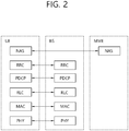
- FIG. 2 shows a control plane of a radio interface protocol of an LTE system.
- FIG. 3 shows a user plane of a radio interface protocol of an LTE system.
- Layers of a radio interface protocol between the UE and the E-UTRAN may be classified into a first layer (LI), a second layer (L2), and a third layer (L3) based on the lower three layers of the open system interconnection (OSI) model that is well-known in the communication system.
- the radio interface protocol between the UE and the E-UTRAN may be horizontally divided into a physical layer, a data link layer, and a network layer, and may be vertically divided into a control plane (C-plane) which is a protocol stack for control signal transmission and a user plane (U-plane) which is a protocol stack for data information transmission.
- C-plane control plane
- U-plane user plane
- the layers of the radio interface protocol exist in pairs at the UE and the E-UTRAN, and are in charge of data transmission of the Uu interface.
- a physical (PHY) layer belongs to the L1.
- the PHY layer provides a higher layer with an information transfer service through a physical channel.
- the PHY layer is connected to a medium access control (MAC) layer, which is a higher layer of the PHY layer, through a transport channel.
- MAC medium access control
- a physical channel is mapped to the transport channel.
- Data is transferred between the MAC layer and the PHY layer through the transport channel.
- the physical channel is modulated using an orthogonal frequency division multiplexing (OFDM) scheme, and utilizes time and frequency as a radio resource.
- OFDM orthogonal frequency division multiplexing
- the PHY layer uses several physical control channels.
- a physical downlink control channel (PDCCH) reports to a UE about resource allocation of a paging channel (PCH) and a downlink shared channel (DL-SCH), and hybrid automatic repeat request (HARQ) information related to the DL-SCH.
- the PDCCH may carry a UL grant for reporting to the UE about resource allocation of UL transmission.
- a physical control format indicator channel (PCFICH) reports the number of OFDM symbols used for PDCCHs to the UE, and is transmitted in every subframe.
- a physical hybrid ARQ indicator channel (PHICH) carries an HARQ acknowledgement (ACK)/non-acknowledgement (NACK) signal in response to UL transmission.
- ACK HARQ acknowledgement
- NACK non-acknowledgement
- a physical uplink control channel (PUCCH) carries UL control information such as HARQ ACK/NACK for DL transmission, scheduling request, and CQI.
- a physical uplink shared channel (PUSCH) carries a UL-uplink shared channel (SCH).
- a physical channel consists of a plurality of subframes in time domain and a plurality of subcarriers in frequency domain.
- One subframe consists of a plurality of symbols in the time domain.
- One subframe consists of a plurality of resource blocks (RBs).
- One RB consists of a plurality of symbols and a plurality of subcarriers.
- each subframe may use specific subcarriers of specific symbols of a corresponding subframe for a PDCCH. For example, a first symbol of the subframe may be used for the PDCCH.
- the PDCCH carries dynamic allocated resources, such as a physical resource block (PRB) and modulation and coding scheme (MCS).
- a transmission time interval (TTI) which is a unit time for data transmission may be equal to a length of one subframe. The length of one subframe may be 1 ms.
- a DL transport channel for transmitting data from the network to the UE includes a broadcast channel (BCH) for transmitting system information, a paging channel (PCH) for transmitting a paging message, a DL-SCH for transmitting user traffic or control signals, etc.
- BCH broadcast channel
- PCH paging channel
- DL-SCH DL-SCH for transmitting user traffic or control signals
- the DL-SCH supports HARQ, dynamic link adaptation by varying the modulation, coding and transmit power, and both dynamic and semi-static resource allocation.
- the DL-SCH also may enable broadcast in the entire cell and the use of beamforming.
- the system information carries one or more system information blocks. All system information blocks may be transmitted with the same periodicity. Traffic or control signals of a multimedia broadcast/multicast service (MBMS) may be transmitted through the DL-SCH or a multicast channel (MCH).
- MCH multicast channel
- a UL transport channel for transmitting data from the UE to the network includes a random access channel (RACH) for transmitting an initial control message, a UL-SCH for transmitting user traffic or control signals, etc.
- RACH random access channel
- the UL-SCH supports HARQ and dynamic link adaptation by varying the transmit power and potentially modulation and coding.
- the UL-SCH also may enable the use of beamforming.
- the RACH is normally used for initial access to a cell.
- a MAC layer belongs to the L2.
- the MAC layer provides services to a radio link control (RLC) layer, which is a higher layer of the MAC layer, via a logical channel.
- RLC radio link control
- the MAC layer provides a function of mapping multiple logical channels to multiple transport channels.
- the MAC layer also provides a function of logical channel multiplexing by mapping multiple logical channels to a single transport channel.
- a MAC sublayer provides data transfer services on logical channels.
- the logical channels are classified into control channels for transferring control plane information and traffic channels for transferring user plane information, according to a type of transmitted information. That is, a set of logical channel types is defined for different data transfer services offered by the MAC layer.
- the logical channels are located above the transport channel, and are mapped to the transport channels.
- the control channels are used for transfer of control plane information only.
- the control channels provided by the MAC layer include a broadcast control channel (BCCH), a paging control channel (PCCH), a common control channel (CCCH), a multicast control channel (MCCH) and a dedicated control channel (DCCH).
- the BCCH is a downlink channel for broadcasting system control information.
- the PCCH is a downlink channel that transfers paging information and is used when the network does not know the location cell of a UE.
- the CCCH is used by UEs having no RRC connection with the network.
- the MCCH is a point-to-multipoint downlink channel used for transmitting MBMS control information from the network to a UE.
- the DCCH is a point-to-point bi-directional channel used by UEs having an RRC connection that transmits dedicated control information between a UE and the network.
- Traffic channels are used for the transfer of user plane information only.
- the traffic channels provided by the MAC layer include a dedicated traffic channel (DTCH) and a multicast traffic channel (MTCH).
- DTCH dedicated traffic channel
- MTCH multicast traffic channel
- the DTCH is a point-to-point channel, dedicated to one UE for the transfer of user information and can exist in both uplink and downlink.
- the MTCH is a point-to-multipoint downlink channel for transmitting traffic data from the network to the UE.
- Uplink connections between logical channels and transport channels include the DCCH that can be mapped to the UL-SCH, the DTCH that can be mapped to the UL-SCH and the CCCH that can be mapped to the UL-SCH.
- Downlink connections between logical channels and transport channels include the BCCH that can be mapped to the BCH or DL-SCH, the PCCH that can be mapped to the PCH, the DCCH that can be mapped to the DL-SCH, and the DTCH that can be mapped to the DL-SCH, the MCCH that can be mapped to the MCH, and the MTCH that can be mapped to the MCH.
- An RLC layer belongs to the L2.
- the RLC layer provides a function of adjusting a size of data, so as to be suitable for a lower layer to transmit the data, by concatenating and segmenting the data received from an upper layer in a radio section.
- QoS quality of service
- the RLC layer provides three operation modes, i.e., a transparent mode (TM), an unacknowledged mode (UM), and an acknowledged mode (AM).
- TM transparent mode
- UM unacknowledged mode
- AM acknowledged mode
- the AM RLC provides a retransmission function through an automatic repeat request (ARQ) for reliable data transmission.
- a function of the RLC layer may be implemented with a functional block inside the MAC layer. In this case, the RLC layer may not exist.
- a packet data convergence protocol (PDCP) layer belongs to the L2.
- the PDCP layer provides a function of header compression function that reduces unnecessary control information such that data being transmitted by employing IP packets, such as IPv4 or IPv6, can be efficiently transmitted over a radio interface that has a relatively small bandwidth.
- the header compression increases transmission efficiency in the radio section by transmitting only necessary information in a header of the data.
- the PDCP layer provides a function of security.
- the function of security includes ciphering which prevents inspection of third parties, and integrity protection which prevents data manipulation of third parties.
- a radio resource control (RRC) layer belongs to the L3.
- the RLC layer is located at the lowest portion of the L3, and is only defined in the control plane.
- the RRC layer takes a role of controlling a radio resource between the UE and the network. For this, the UE and the network exchange an RRC message through the RRC layer.
- the RRC layer controls logical channels, transport channels, and physical channels in relation to the configuration, reconfiguration, and release of RBs.
- An RB is a logical path provided by the L1 and L2 for data delivery between the UE and the network. That is, the RB signifies a service provided the L2 for data transmission between the UE and E-UTRAN.
- the configuration of the RB implies a process for specifying a radio protocol layer and channel properties to provide a particular service and for determining respective detailed parameters and operations.
- the RB is classified into two types, i.e., a signaling RB (SRB) and a data RB (DRB).
- SRB signaling RB
- DRB data RB
- the SRB is used as a path for transmitting an RRC message in the control plane.
- the DRB is used as a path for transmitting user data in the user plane.
- a Non-Access Stratum (NAS) layer placed over the RRC layer performs functions, such as session management and mobility management.
- functions such as session management and mobility management.
- the RLC and MAC layers may perform functions such as scheduling, automatic repeat request (ARQ), and hybrid automatic repeat request (HARQ).
- the RRC layer (terminated in the eNB on the network side) may perform functions such as broadcasting, paging, RRC connection management, RB control, mobility functions, and UE measurement reporting and controlling.
- the NAS control protocol (terminated in the MME of gateway on the network side) may perform functions such as a SAE bearer management, authentication, LTE_IDLE mobility handling, paging origination in LTE_IDLE, and security control for the signaling between the gateway and UE.
- the RLC and MAC layers may perform the same functions for the control plane.
- the PDCP layer may perform the user plane functions such as header compression, integrity protection, and ciphering.
- An RRC state indicates whether an RRC layer of the UE is logically connected to an RRC layer of the E-UTRAN.
- the RRC state may be divided into two different states such as an RRC connected state and an RRC idle state.
- RRC connection When an RRC connection is established between the RRC layer of the UE and the RRC layer of the E-UTRAN, the UE is in RRC_CONNECTED, and otherwise the UE is in RRC_IDLE. Since the UE in RRC_CONNECTED has the RRC connection established with the E-UTRAN, the E-UTRAN may recognize the existence of the UE in RRC_CONNECTED and may effectively control the UE.
- the UE in RRC_IDLE may not be recognized by the E-UTRAN, and a CN manages the UE in unit of a TA which is a larger area than a cell. That is, only the existence of the UE in RRC_IDLE is recognized in unit of a large area, and the UE must transition to RRC_CONNECTED to receive a typical mobile communication service such as voice or data communication.
- the UE may receive broadcasts of system information and paging information while the UE specifies a discontinuous reception (DRX) configured by NAS, and the UE has been allocated an identification (ID) which uniquely identifies the UE in a tracking area and may perform public land mobile network (PLMN) selection and cell re-selection. Also, in RRC_IDLE state, no RRC context is stored in the eNB.
- DRX discontinuous reception
- PLMN public land mobile network
- the UE In RRC_CONNECTED state, the UE has an E-UTRAN RRC connection and a context in the E-UTRAN, such that transmitting and/or receiving data to/from the eNB becomes possible. Also, the UE can report channel quality information and feedback information to the eNB.
- the E-UTRAN knows the cell to which the UE belongs. Therefore, the network can transmit and/or receive data to/from UE, the network can control mobility (handover and inter-radio access technologies (RAT) cell change order to GSM EDGE radio access network (GERAN) with network assisted cell change (NACC)) of the UE, and the network can perform cell measurements for a neighboring cell.
- RAT inter-radio access technologies
- GERAN GSM EDGE radio access network
- NACC network assisted cell change
- the UE specifies the paging DRX cycle. Specifically, the UE monitors a paging signal at a specific paging occasion of every UE specific paging DRX cycle.
- the paging occasion is a time interval during which a paging signal is transmitted.
- the UE has its own paging occasion.
- a paging message is transmitted over all cells belonging to the same tracking area. If the UE moves from one TA to another TA, the UE will send a tracking area update (TAU) message to the network to update its location.
- TAU tracking area update
- the UE When the user initially powers on the UE, the UE first searches for a proper cell and then remains in RRC_IDLE in the cell. When there is a need to establish an RRC connection, the UE which remains in RRC_IDLE establishes the RRC connection with the RRC of the E-UTRAN through an RRC connection procedure and then may transition to RRC_CONNECTED. The UE which remains in RRC_IDLE may need to establish the RRC connection with the E-UTRAN when uplink data transmission is necessary due to a user's call attempt or the like or when there is a need to transmit a response message upon receiving a paging message from the E-UTRAN.
- EMM-REGISTERED EPS mobility management-REGISTERED
- EMM-DEREGISTERED EMM-DEREGISTERED
- ECM EPS connection management
- ECM-CONNECTED ECM-CONNECTED
- the UE in the ECM-IDLE state performs a UE-based mobility related procedure such as cell selection or reselection without having to receive a command of the network.
- a UE-based mobility related procedure such as cell selection or reselection without having to receive a command of the network.
- mobility of the UE is managed by the command of the network. If a location of the UE in the ECM-IDLE state becomes different from a location known to the network, the UE reports the location of the UE to the network through a tracking area update procedure.
- FIG. 4 shows a procedure in which UE that is initially powered on experiences a cell selection process, registers it with a network, and then performs cell reselection if necessary.
- the UE selects Radio Access Technology (RAT) in which the UE communicates with a Public Land Mobile Network (PLMN), that is, a network from which the UE is provided with service (S410).
- RAT Radio Access Technology
- PLMN Public Land Mobile Network
- S410 a network from which the UE is provided with service
- Information about the PLMN and the RAT may be selected by the user of the UE, and the information stored in a Universal Subscriber Identity Module (USIM) may be used.
- USIM Universal Subscriber Identity Module
- the UE selects a cell that has the greatest value and that belongs to cells having measured BS and signal intensity or quality greater than a specific value (cell selection) (S420).
- cell selection a specific value
- the UE that is powered off performs cell selection, which may be called initial cell selection.
- a cell selection procedure is described later in detail.
- the UE receives system information periodically by the BS.
- the specific value refers to a value that is defined in a system in order for the quality of a physical signal in data transmission/reception to be guaranteed. Accordingly, the specific value may differ depending on applied RAT.
- the UE performs a network registration procedure (S430).
- the UE registers its information (e.g., an IMSI) with the network in order to receive service (e.g., paging) from the network.
- the UE does not register it with a network whenever it selects a cell, but registers it with a network when information about the network (e.g., a Tracking Area Identity (TAI)) included in system information is different from information about the network that is known to the UE.
- TAI Tracking Area Identity
- the UE performs cell reselection based on a service environment provided by the cell or the environment of the UE (S440). If the value of the intensity or quality of a signal measured based on a BS from which the UE is provided with service is lower than that measured based on a BS of a neighboring cell, the UE selects a cell that belongs to other cells and that provides better signal characteristics than the cell of the BS that is accessed by the UE. This process is called cell reselection differently from the initial cell selection of the No. 2 process. In this case, temporal restriction conditions are placed in order for a cell to be frequently reselected in response to a change of signal characteristic. A cell reselection procedure is described later in detail.
- FIG. 5 shows an RRC connection establishment procedure
- the UE sends an RRC connection request message that requests RRC connection to a network (S510).
- the network sends an RRC connection establishment message as a response to the RRC connection request (S520). After receiving the RRC connection establishment message, the UE enters RRC connected mode.
- the UE sends an RRC connection establishment complete message used to check the successful completion of the RRC connection to the network (S530).
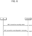
- FIG. 6 shows an RRC connection reconfiguration procedure.
- RRC connection reconfiguration is used to modify RRC connection. This is used to establish/modify/release RBs, perform handover, and set up/modify/release measurements.
- a network sends an RRC connection reconfiguration message for modifying RRC connection to UE (S610).
- the UE sends an RRC connection reconfiguration complete message used to check the successful completion of the RRC connection reconfiguration to the network (S620).
- the UE When power is turned-on or the UE is located in a cell, the UE performs procedures for receiving a service by selecting/reselecting a suitable quality cell.
- a UE in an RRC idle state should prepare to receive a service through the cell by always selecting a suitable quality cell. For example, a UE where power is turned-on just before should select the suitable quality cell to be registered in a network. If the UE in an RRC connection state enters in an RRC idle state, the UE should selects a cell for stay in the RRC idle state. In this way, a procedure of selecting a cell satisfying a certain condition by the UE in order to be in a service idle state such as the RRC idle state refers to cell selection. Since the cell selection is performed in a state that a cell in the RRC idle state is not currently determined, it is important to select the cell as rapid as possible. Accordingly, if the cell provides a wireless signal quality of a predetermined level or greater, although the cell does not provide the best wireless signal quality, the cell may be selected during a cell selection procedure of the UE.
- a cell selection process is basically divided into two types.
- the first is an initial cell selection process.
- UE does not have preliminary information about a wireless channel. Accordingly, the UE searches for all wireless channels in order to find out a proper cell. The UE searches for the strongest cell in each channel. Thereafter, if the UE has only to search for a suitable cell that satisfies a cell selection criterion, the UE selects the corresponding cell.
- the UE may select the cell using stored information or using information broadcasted by the cell. Accordingly, cell selection may be fast compared to an initial cell selection process. If the UE has only to search for a cell that satisfies the cell selection criterion, the UE selects the corresponding cell. If a suitable cell that satisfies the cell selection criterion is not retrieved though such a process, the UE performs an initial cell selection process.
- the intensity or quality of a signal between the UE and a BS may be changed due to a change in the mobility or wireless environment of the UE. Accordingly, if the quality of the selected cell is deteriorated, the UE may select another cell that provides better quality. If a cell is reselected as described above, the UE selects a cell that provides better signal quality than the currently selected cell. Such a process is called cell reselection. In general, a basic object of the cell reselection process is to select a cell that provides UE with the best quality from a viewpoint of the quality of a radio signal.
- a network may determine priority corresponding to each frequency, and may inform the UE of the determined priorities.
- the UE that has received the priorities preferentially takes into consideration the priorities in a cell reselection process compared to a radio signal quality criterion.
- the following cell reselection methods may be present according to the RAT and frequency characteristics of the cell.
- UE measures the quality of a serving cell and neighbor cells for cell reselection.
- cell reselection is performed based on a cell reselection criterion.
- the cell reselection criterion has the following characteristics in relation to the measurements of a serving cell and neighbor cells.
- Intra-frequency cell reselection is basically based on ranking.
- Ranking is a task for defining a criterion value for evaluating cell reselection and numbering cells using criterion values according to the size of the criterion values.
- a cell having the best criterion is commonly called the best-ranked cell.
- the cell criterion value is based on the value of a corresponding cell measured by UE, and may be a value to which a frequency offset or cell offset has been applied, if necessary.
- Inter-frequency cell reselection is based on frequency priority provided by a network.
- UE attempts to camp on a frequency having the highest frequency priority.
- a network may provide frequency priority that will be applied by UEs within a cell in common through broadcasting signaling, or may provide frequency-specific priority to each UE through UE-dedicated signaling.
- a cell reselection priority provided through broadcast signaling may refer to a common priority.
- a cell reselection priority for each UE set by a network may refer to a dedicated priority. If receiving the dedicated priority, the UE may receive a valid time associated with the dedicated priority together. If receiving the dedicated priority, the UE starts a validity timer set as the received valid time together therewith. While the valid timer is operated, the UE applies the dedicated priority in the RRC idle mode. If the valid timer is expired, the UE discards the dedicated priority and again applies the common priority.
- a network may provide UE with a parameter (e.g., a frequency-specific offset) used in cell reselection for each frequency.
- a parameter e.g., a frequency-specific offset
- a network may provide UE with a Neighboring Cell List (NCL) used in cell reselection.
- NCL Neighboring Cell List
- the NCL includes a cell-specific parameter (e.g., a cell-specific offset) used in cell reselection.
- a network may provide UE with a cell reselection black list used in cell reselection. The UE does not perform cell reselection on a cell included in the black list.
- a ranking criterion used to apply priority to a cell is defined as in Equation 1.
- R S Q meas , s + Q hyst
- R n Q meas , n ⁇ Q offset
- Rs is the ranking criterion of a serving cell
- Rn is the ranking criterion of a neighbor cell
- Qmeas,s is the quality value of the serving cell measured by UE
- Qmeas,n is the quality value of the neighbor cell measured by UE
- Qhyst is the hysteresis value for ranking
- Qoffset is an offset between the two cells.
- ranking priority is frequency changed as a result of the change, and UE may alternately reselect the twos.
- Qhyst is a parameter that gives hysteresis to cell reselection so that UE is prevented from to alternately reselecting two cells.
- UE measures RS of a serving cell and Rn of a neighbor cell according to the above equation, considers a cell having the greatest ranking criterion value to be the best-ranked cell, and reselects the cell. If a reselected cell is not a suitable cell, UE excludes a corresponding frequency or a corresponding cell from the subject of cell reselection.
- FIG. 7 shows an RRC connection re-establishment procedure.
- UE stops using all the radio bearers that have been configured other than a Signaling Radio Bearer (SRB) #0, and initializes a variety of kinds of sublayers of an Access Stratum (AS) (S710). Furthermore, the UE configures each sublayer and the PHY layer as a default configuration. In this procedure, the UE maintains the RRC connection state.
- SRB Signaling Radio Bearer
- AS Access Stratum
- the UE performs a cell selection procedure for performing an RRC connection reconfiguration procedure (S720).
- the cell selection procedure of the RRC connection re-establishment procedure may be performed in the same manner as the cell selection procedure that is performed by the UE in the RRC idle state, although the UE maintains the RRC connection state.
- the UE determines whether or not a corresponding cell is a suitable cell by checking the system information of the corresponding cell (S730). If the selected cell is determined to be a suitable E-UTRAN cell, the UE sends an RRC connection re-establishment request message to the corresponding cell (S740).
- the UE stops the RRC connection re-establishment procedure and enters the RRC idle state (S750).
- the UE may be implemented to finish checking whether the selected cell is a suitable cell through the cell selection procedure and the reception of the system information of the selected cell. To this end, the UE may drive a timer when the RRC connection re-establishment procedure is started. The timer may be stopped if it is determined that the UE has selected a suitable cell. If the timer expires, the UE may consider that the RRC connection re-establishment procedure has failed, and may enter the RRC idle state. Such a timer is hereinafter called an RLF timer. In LTE spec TS 36.331, a timer named "T311" may be used as an RLF timer. The UE may obtain the set value of the timer from the system information of the serving cell.
- a cell sends an RRC connection re-establishment message to the UE.
- the UE that has received the RRC connection re-establishment message from the cell reconfigures a PDCP sublayer and an RLC sublayer with an SRB1. Furthermore, the UE calculates various key values related to security setting, and reconfigures a PDCP sublayer responsible for security as the newly calculated security key values. Accordingly, the SRB 1 between the UE and the cell is open, and the UE and the cell may exchange RRC control messages. The UE completes the restart of the SRB1, and sends an RRC connection re-establishment complete message indicative of that the RRC connection re-establishment procedure has been completed to the cell (S760).
- the cell sends an RRC connection re-establishment reject message to the UE.
- the cell and the UE perform an RRC connection reconfiguration procedure. Accordingly, the UE recovers the state prior to the execution of the RRC connection re-establishment procedure, and the continuity of service is guaranteed to the upmost.
- FIG. 8 shows a conventional method of performing measurement.
- a UE receives measurement configuration information from a BS (S810).
- a message including the measurement configuration information is referred to as a measurement configuration message.
- the UE performs measurement based on the measurement configuration information (S820). If a measurement result satisfies a reporting condition included in the measurement configuration information, the UE reports the measurement result to the BS (S830).
- a message including the measurement result is referred to as a measurement report message.
- the measurement configuration information may include the following information.
- the UE To perform a measurement procedure, the UE has a measurement object, a reporting configuration, and a measurement identity.
- the BS can assign only one measurement object to the UE with respect to one frequency. Events for triggering measurement reporting are shown in the table 1. If the measurement result of the UE satisfies the determined event, the UE transmits a measurement report message to the BS.
- the measurement report may include the measurement identity, a measured quality of the serving cell, and a measurement result of the neighbor cell.
- the measurement identity identifies a measurement object in which the measurement report is triggered.
- the measurement result of the neighbor cell may include a cell identity and a measurement quality of the neighbor cell.
- the measured quality may include at least one of reference signal received power (RSRP) and reference signal received quality (RSRQ).
- FIG. 9 shows the structure of a wireless local area network (WLAN).
- FIG. 9(a) shows the structure of an infrastructure network of Institute of Electrical and Electronics Engineers (IEEE) 802.11.
- FIG. 9(b) shows an independent BSS.
- IEEE Institute of Electrical and Electronics Engineers
- a WLAN system may include one or more basic service sets (BSSs) 900 and 905.
- the BSSs 900 and 905 are a set of an access point (AP) and a station (STA), such as an AP 925 and STA1 900-1, which are successfully synchronized to communicate with each other, and are not a concept indicating a specific region.
- the BSS 905 may include one AP 930 and one or more STAs 905-1 and 905-2 that may be connected to the AP 930.
- An infrastructure BSS may include at least one STA, APs 925 and 930 providing a distribution service, and a distribution system (DS) 910 connecting a plurality of APs.
- the distribution system 910 may configure an extended service set (ESS) 940 by connecting a plurality of BSSs 900 and 905.
- ESS 940 may be used as a term indicating one network configured by connecting one or more APs 925 or 930 through the distribution system 910.
- APs included in one ESS 940 may have the same service set identification (SSID).
- SSID service set identification
- a portal 920 may serve as a bridge that connects the WLAN (IEEE 802.11) and another network (for example, 802.X).
- a network between the APs 925 and 930 and a network between the APs 925 and 930 and the STAs 900-1, 905-1, and 905-2 may be configured.
- a network configured between STAs in the absence of the APs 925 and 930 to perform communication is defined as an ad hoc network or independent basic service set (BSS).
- an independent BSS is a BSS that operates in an ad hoc mode.
- the IBSS includes no AP and thus has no centralized management entity that performs a management function at the center. That is, in the IBSS, STAs 950-1, 950-2, 950-3, 955-4, and 955-5 are managed in a distributed manner. In the IBSS, all STAs 950-1, 950-2, 950-3, 955-4, and 955-5 may be mobile STAs. Further, the STAs are not allowed to access the DS and thus establish a self-contained network.
- An STA is a functional medium including medium access control (MAC) and a physical layer interface for a radio medium according to IEEE 802.11 specifications and may be used to broadly mean both an AP and a non-AP STA.
- MAC medium access control
- IEEE 802.11 specifications
- An STA may also be referred to as various names, such as a mobile terminal, a wireless device, a wireless transmit/receive unit (WTRU), user equipment (UE), a mobile station (MS), a mobile subscriber unit, or simply a user.
- WTRU wireless transmit/receive unit
- UE user equipment
- MS mobile station
- subscriber unit simply a user.
- a 3GPP introduces interworking with a non-3GPP access network (e.g. WLAN) from Rel-8 to find accessible access network, and regulates ANDSF (Access Network Discovery and Selection Functions) for selection.
- An ANDSF transfers accessible access network finding information (e.g. WLAN, WiMAX location information and the like), Inter-System Mobility Policies (ISMP) capable of reflecting policies of a business, and an Inter-System Routing Policy (ISRP).
- the UE may determine whether to transmit certain IP traffic through a certain access network.
- An ISMP may include a network selection rule with respect to selection of one active access network connection (e.g., WLAN or 3GPP) by the UE.
- An ISRP may include a network selection rule with respect to selection of at least one potential active access network connection (e.g., both of WLAN and 3GPP) by the UE.
- the ISRP includes Multiple Access PDN Connectivity (MAPCON), IP Flow Mobility (IFOM), and non-seamless WLAN offloading.
- MAPCON Multiple Access PDN Connectivity
- IFOM IP Flow Mobility
- OMA DM Open Mobile Alliance Device Management
- the MAPCON simultaneously configures and maintains a plurality of packet data networks (multiple PDN connectivity) through a 3GPP access network and a non-3GPP access network and regulates a technology capable of performing seamless traffic offloading in the whole active PDN connection unit.
- an ANDSF server provides APN (Access Point Name) information to perform offloading, inter-access network priority (routing rule), Time of Day to which offloading method is applied, and access network (Validity Area) information to be offloaded.
- APN Access Point Name
- the IFOM supports mobility and seamless offloading of an IP flow unit of flexible subdivided unit as compared with the MAPCON.
- a technical characteristic of the IFOM allows a UE to access through different access network when the UE is connected to a packet data network using an access point name (APN). Mobility and a unit of offloading may be moved in a specific service IP traffic flow unit which is not a packet data network (PDN), the technical characteristic of the IFOM has flexibility of providing a service.
- an ANDSF server provides IP flow information to perform offloading, priority (routing rule) between access networks, Time of Day to which an offloading method is applied, and Validity Area where offloading is performed.
- the non-seamless WLAN offloading refers to a technology which changes a certain path of a specific IP traffic to a WLAN and completely offloads traffic without passing through an EPC. Since the non-seamless WLAN offloading is not anchored in P-GW for supporting mobility, offloaded IP traffic may not continuously moved to a 3GPP access network. To this end, the ANDSF server provides information similar to information to be provided for performing an IFOM.
- FIG. 10 shows an example of an environment where a 3GPP access network and a WLAN access network coexist.
- a cell 1 centering a base station 1 (1010) and a cell 2 centering a base station 2 (1020) are deployed as a 3GPP access network.
- a BSS3 centering an AP3 (1050) located in a cell 2 is deployed. Coverage of the cell is shown with a solid line, and coverage of BSS is shown with a dotted line.
- the UE 1000 is configured to perform communication through a 3GPP access network and a WLAN access network.
- the UE 1000 may refer to a station.
- the UE 1000 may establish connection with a BS1 (1010) in a cell 1 to perform traffic through a 3GPP access network.
- the UE 1000 may enters coverage of BSS1 while moving into coverage of cell 1.
- the UE 1000 may connect with a WLAN access network by performing association and authentication procedures with an AP1 (1030) of BSS1.
- the UE 1000 may process traffic through a 3GPP access network and a WLAN access network. Meanwhile, the UE 1000 moves and is separated from the coverage BSS1, connection with a WLAN access network may be terminated.
- the UE 1000 continuously move into the coverage of cell 1 and move around a boundary between cell 1 and cell 2, and enters coverage of BSS2 to find BSS2 through scanning.
- the UE 1000 may connect with the WLAN access network by performing association and authentication procedures of AP2 (1040) of the BSS2. Meanwhile, since the UE 1000 in the coverage of the BSS2 is located at a boundary between the cell 1 and the cell 2, service quality through the 3GPP access network may not be excellent.
- the UE 1000 may operate to mainly process traffic through a WLAN access network.
- the UE 1000 may terminate connection with the WLAN access network and may process traffic through a 3GPP access network based on the cell 2.
- the UE 1000 may enter coverage of the BSS3 while moving into the coverage of cell 2 to find the BSS1 through scanning.
- the UE 1000 may connect with the WLAN access network by association and authentication procedures of an AP3 (1050) of the BSS3. Accordingly, the UE 1000 may process the traffic through the 3GPP access network and the WLAN access network.
- the UE may adaptively process traffic through a 3GPP access network and/or a non-3GPP access network.
- the above ANDSF may be configured. If the ANDSF is configured, the UE may process traffic of the 3GPP access network through a non-3GPP access network or a 3GPP access network.
- interworking policies except for the ANDSF may be configured.
- interworking policies reflecting measurement parameters such as load and signal quality of the 3GPP access and/or the WLAN access network are defined.
- the policy refers to an RAN policy.
- a traffic steering rule according to an RAN policy refers to an RAN rule.
- the RAN rule may be provided to the UE together with at least one RAN rule parameter for evaluating traffic steering according to the RAN rule.
- the RAN rule and the RAN rule parameter may be configured as follows.
- the ANDSF configured in the UE may include a legacy ANDSF and/or an enhanced ANDSF.
- the legacy ANDSF may be defined as an ANDSF which does not include ANDSF management object (MO) such as corresponding parameters defined in the RAN rule parameter.
- the enhanced ANDSF may be defined as an ANDSF including an ANDSF MO such as corresponding parameters defined in a RAN rule parameter.
- FIG. 11 shows an example of a legacy ANDSF with respect to an MAPCON
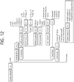
- FIG. 12 shows an example of an enhanced ANDSF with respect to the MAPCON.
- the legacy ANDSF does not include an RAN rule parameter such as RSRP and a WLAN signal level as an ANDSF MO.
- the enhanced ANDSF may include RSRP, RSRQ, and an offload preference as the ANDSF MO. Further, the ANDSF may include a WLAN signal level (e.g. RSSI, RSCP), a WLAN load level, a WLAN backhaul data rate, and a WLAN backhaul load.
- a WLAN signal level e.g. RSSI, RSCP
- the enhanced ANDSF may specify the traffic steering evaluation condition associated with each ANDSF MO.
- the traffic steering evaluation condition specified by the enhanced ANDSF may be configured similar to the traffic steering evaluation condition associated with the configured RAN rule parameter configured by the RAN rule. A detailed description thereof will be omitted.
- the UE may reject the LTE/WLAN aggregation configuration or the LTE/WLAN interworking configuration from a network. If the UE does not have traffic that can be offloaded, the UE may not be able to perform the LTE/WLAN aggregation configuration or the LTE/WLAN interworking configuration. Alternatively, if a user preference does not allow the LTE/WLAN aggregation or the LTE/WLAN interworking, the UE may not be able to perform the LTE/WLAN aggregation configuration or the LTE/WLAN interworking configuration.
- a BS does not know when the UE is able to perform the LTE/WLAN aggregation or the LTE/WLAN interworking. Therefore, the BS may continuously attempt to ask the UE about whether the LTE/WLAN aggregation or the LTE/WLAN interworking is available. Alternatively, the BS may continuously attempt to reconfigure the LTE/WLAN aggregation or the LTE/WLAN interworking.
- the UE may need to report to the network whether traffic offloading to the WLAN is available.
- a method of transmitting a WLAN offloading availability indication by the UE and a device supporting the method will be described according to an embodiment of the present invention.
- a UE may report to a BS that traffic offloading to a WLAN is available.
- the traffic offloading may be any one of LTE/WLAN aggregation and LTE/WLANL interworking. It may be reported that the traffic offloading to the WLAN is available by transmitting a WLAN offloading availability indication to the BS.
- the WLAN offloading indication indicating that the traffic offloading is available may be transmitted to the BS when a state where the traffic offloading is unavailable is changed to a state where the traffic offloading is available.
- the WLAN offloading availability indication may be transmitted to the BS when at least any one of the following conditions is satisfied.
- the UE may have traffic to be transmitted/received, and the traffic may be offloaded to the WLAN. Alternatively, the UE adjusts a part of traffic from LTE to WLAN.
- the UE may report to the BS that the traffic offloading to the WLAN is available.
- a UE may report to a BS that traffic offloading to a WLAN is unavailable.
- the traffic offloading may be any one of LTE/WLAN aggregation and LTE/WLANL interworking. It may be reported that the traffic offloading to the WLAN is unavailable by transmitting a WLAN offloading availability indication to the BS.
- the WLAN offloading availability indication may be transmitted to the BS when at least any one of the following conditions is satisfied.
- the UE does not have traffic that can be offloaded on LTE.
- the UE does not have the traffic that can be offloaded on the LTE since the UE ends offloading of the traffic that can be offloaded or the UE adjusts a part of traffic from the LTE to the WLAN.
- the UE may report to the BS a reason why WLAN offloading is unavailable. For example, since the UE does not have traffic that can be offloaded, it may be reported to the BS that the LTE/WLAN aggregation or the LTE/WLAN interworking is unavailable. For example, since the WLAN module is off, the UE may report to the BS that the LTE/WLAN aggregation or the LTE/WLAN interworking is unavailable. For example, since a user preference does not allow to start the LTE/WLAN aggregation or the LTE/WLAN interworking, the UE may report to the BS that the LTE/WLAN aggregation or the LTE/WLAN interworking is unavailable.
- the WLAN offloading availability indication may indicate whether the traffic offloading is available or unavailable.
- a UE may transmit a WLAN offloading availability indication within an availability indication period.
- the UE may transmit the WLAN offloading availability indication only within the availability indication period.
- the WLAN offloading availability indication may indicate that traffic offloading is available. For example, if a state where the traffic offloading is unavailable is changed to a state where the traffic offloading is available within the availability indication period, the UE may transmit to a BS the WLAN offloading indication indicating that the traffic offloading is available.
- FIG. 13 shows a procedure of transmitting a WLAN offloading availability indication by a UE according to an embodiment of the present invention.
- the UE may receive a WLAN offloading availability request (S1310).
- the WLAN offloading availability request may instruct the UE to transmit to a network whether it is available to perform LTE/WLAN aggregation or LTE/WLAN interworking. Thereafter, the UE may start an availability indication timer.
- the UE may transmit a WLAN offloading availability response (S1320).
- a WLAN offloading availability response may indicate that the traffic offloading is unavailable.
- the UE may start the availability indication timer. It is assumed that the user preference is changed to allow the start of the LTE/WLAN aggregation or the LTE/WLAN interworking after the availability indication time is stared. That is, it is assumed that traffic offloading is available.
- the UE may transmit the WLAN offloading availability indication (S1330).
- the WLAN offloading availability indication may indicate that the traffic offloading is available.
- the network may determine that the traffic offloading is not necessary. Therefore, the availability indication period may not be stopped. Thereafter, it is assumed that the UE ends specific traffic and does no long have traffic that can be offloaded. That is, again, it is assumed that the traffic offloading is unavailable.
- the UE may transmit the WLAN offloading availability indication (S1340).
- the WLAN offloading availability indication may indicate that the traffic offloading is unavailable. Thereafter, again, it is assumed that the UE starts specific traffic, and is able to offload it to the WLAN.
- the UE may transmit the WLAN offloading availability indication (S1350).
- the WLAN offloading availability indication may indicate that the traffic offloading is available.
- the UE may receive from the network a traffic offloading configuration (S1360).
- the traffic offloading configuration may be an LTE/WLAN aggregation configuration or an LTE/WLAN interworking configuration. If the UE is able to perform the traffic offloading configuration, the UE may stop an available indication period. Alternatively, if the availability indication timer expires, the UE may stop the availability indication period.
- FIG. 14 is a block diagram showing a method of transmitting a WLAN offloading availability indication by a UE according to an embodiment of the present invention.
- the UE may determine whether traffic offloading to a WLAN is available (S1410).
- the UE may transmit to a network the WLAN offloading availability indication indicating whether the traffic offloading is available (S 1420).
- the WLAN offloading availability indication may indicate that the traffic offloading is available.
- the WLAN may be on.
- a user preference may allow to start the traffic offloading.
- An upper layer may indicate that the traffic offloading is available.
- the traffic offloading may be performed on the basis of LTE/WLAN aggregation or LTE/WLAN interworking.
- the WLAN offloading availability indication may indicate that the traffic offloading is unavailable. If the WLAN is off, the WLAN offloading availability indication may indicate that the traffic offloading is unavailable. If the user preference does not allow to start the traffic offloading, the WLAN offloading availability indication may indicate that the traffic offloading is unavailable. If the upper layer indicates that the traffic offloading is unavailable, the WLAN offloading availability indication may indicate that the traffic offloading is unavailable. The UE may transmit to the network a reason why the traffic offloading is unavailable.
- the WLAN offloading availability indication may be transmitted during an availability indication period.
- the availability indication period may be a period in which an availability indication timer runs.
- the availability indication period may be started after the UE receives a WLAN offloading availability request from the network.
- the availability indication period may be started after the UE transmits to the network the WLAN offloading availability indication indicating that traffic offloading is unavailable.
- the availability indication period may be started when the UE receives the traffic offloading configuration from the network and is unable to perform the traffic offloading on the basis of the traffic offloading configuration.
- the availability indication period may be started when the UE receives the traffic offload configuration from the network and transmits a traffic offloading reject message in response to the traffic offloading configuration.
- the availability indication period may be ended when the UE receives from the network the traffic offloading configuration and is able to perform the traffic offloading on the basis of the traffic offloading configuration.
- the availability indication period may be started when the UE receives from the network a WLAN measurement configuration.
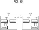
- FIG. 15 is a block diagram illustrating a wireless communication system according to the embodiment of the present invention.
- a BS 1500 includes a processor 1501, a memory 1502 and a transceiver 1503.
- the memory 1502 is connected to the processor 1501, and stores various information for driving the processor 1501.
- the transceiver 1503 is connected to the processor 1501, and transmits and/or receives radio signals.
- the processor 1501 implements proposed functions, processes and/or methods. In the above embodiment, an operation of the base station may be implemented by the processor 1501.
- a UE 1510 includes a processor 1511, a memory 1512 and a transceiver 1513.
- the memory 1512 is connected to the processor 1511, and stores various information for driving the processor 1511.
- the transceiver 1513 is connected to the processor 1511, and transmits and/or receives radio signals.
- the processor 1511 implements proposed functions, processes and/or methods. In the above embodiment, an operation of the UE may be implemented by the processor 1511.
- the processor may include an application-specific integrated circuit (ASIC), a separate chipset, a logic circuit, and/or a data processing unit.
- the memory may include a read-only memory (ROM), a random access memory (RAM), a flash memory, a memory card, a storage medium, and/or other equivalent storage devices.
- the transceiver may include a base-band circuit for processing a wireless signal.
- the aforementioned methods can be implemented with a module (i.e., process, function, etc.) for performing the aforementioned functions.
- the module may be stored in the memory and may be performed by the processor.
- the memory may be located inside or outside the processor, and may be coupled to the processor by using various well-known means.
Landscapes
- Engineering & Computer Science (AREA)
- Computer Networks & Wireless Communication (AREA)
- Signal Processing (AREA)
- Mobile Radio Communication Systems (AREA)
Claims (5)
- Verfahren zur Übertragung einer Verfügbarkeitsinformation für drahtloses lokales Bereichsnetzwerk-, WLAN-, Offloading, das von einem Benutzergerät, UE, in einem drahtlosen Kommunikationssystem ausgeführt wird, wobei das Verfahren aufweist:Empfangen (S1310) einer Verfügbarkeitsanfrage von WLAN-Offloading zum Anfragen der Verfügbarkeit von Verkehrs-Offloading von einer Basisstation;nach dem Empfang der Verfügbarkeitsanfrage für WLAN-Offloading Starten eines Zeitschalters;wenn das WLAN für das Verkehrs-Offloading nicht verfügbar ist, Melden (S1320, S1340) einer Nichtverfügbarkeitsinformation für die Nichtverfügbarkeit des WLAN an die Basisstation, während der Zeitschalter läuft;nach dem Melden der Nichtverfügbarkeitsinformation und wenn das WLAN für das Verkehrs-Offloading verfügbar wird, Melden (S1330, S1350) einer Verfügbarkeitsinformation für die Verfügbarkeit des WLAN an die Basisstation, während der Zeitschalter läuft;Empfangen (S1360) einer Verkehrs-Offloading-Konfiguration von der Basisstation; undnach dem Empfang der Verkehrs-Offloading-Konfiguration Stoppen des Zeitschalters, wobei die Verfügbarkeitsinformationen und die Nichtverfügbarkeitsinformation nur an die Basisstation gemeldet werden, während der Zeitschalter läuft.
- Verfahren nach Anspruch 1, wobei die Verfügbarkeitsinformation gemeldet wird, wenn das UE Verkehr hat, der an das WLAN ausgelagert werden kann und eine Benutzereinstellung es zulässt, das Verkehrs-Offloading zu starten.
- Verfahren nach Anspruch 1, wobei die Nichtverfügbarkeitsinformation gemeldet wird, wenn das UE keinen Verkehr hat, der an das WLAN ausgelagert werden kann, oder eine Benutzereinstellung es nicht zulässt, dass das Verkehrs-Offloading gestartet wird.
- Verfahren nach Anspruch 1, das ferner aufweist:
Übertragen einer Verkehrs-Offloading-Ablehnungsnachricht ansprechend auf die Verkehrs-Offloading-Konfiguration. - Benutzergerät, UE, das geeignet ist, eine Verfügbarkeitsanzeige für drahtloses lokales Bereichsnetzwerk-, WLAN-, Offloading in einem drahtlosen Kommunikationssystem zu übertragen, wobei das UE Einrichtungen (1511, 1512, 1513) aufweist, die geeignet sind, das Verfahren nach einem der Ansprüche 1 bis 4 durchzuführen.
Applications Claiming Priority (4)
| Application Number | Priority Date | Filing Date | Title |
|---|---|---|---|
| US201562170654P | 2015-06-03 | 2015-06-03 | |
| US201562209308P | 2015-08-24 | 2015-08-24 | |
| US201562208831P | 2015-08-24 | 2015-08-24 | |
| PCT/KR2016/005854 WO2016195395A1 (ko) | 2015-06-03 | 2016-06-02 | Wlan 오프로딩 가용성 지시자를 전송하는 방법 및 장치 |
Publications (3)
| Publication Number | Publication Date |
|---|---|
| EP3306977A1 EP3306977A1 (de) | 2018-04-11 |
| EP3306977A4 EP3306977A4 (de) | 2018-10-31 |
| EP3306977B1 true EP3306977B1 (de) | 2020-08-05 |
Family
ID=57440726
Family Applications (1)
| Application Number | Title | Priority Date | Filing Date |
|---|---|---|---|
| EP16803750.5A Active EP3306977B1 (de) | 2015-06-03 | 2016-06-02 | Verfahren und vorrichtung zur übertragung der anzeige der verfügbarkeit von wlan-offloading |
Country Status (3)
| Country | Link |
|---|---|
| US (1) | US10743212B2 (de) |
| EP (1) | EP3306977B1 (de) |
| WO (1) | WO2016195395A1 (de) |
Families Citing this family (2)
| Publication number | Priority date | Publication date | Assignee | Title |
|---|---|---|---|---|
| US10743212B2 (en) * | 2015-06-03 | 2020-08-11 | Lg Electronics Inc. | Method and device for transmitting WLAN offloading availability indication |
| KR102531285B1 (ko) * | 2016-03-25 | 2023-05-12 | 삼성전자주식회사 | 통신 기능을 제공하는 방법 및 이를 위한 전자 장치 |
Family Cites Families (13)
| Publication number | Priority date | Publication date | Assignee | Title |
|---|---|---|---|---|
| CN100574276C (zh) * | 2006-08-22 | 2009-12-23 | 中兴通讯股份有限公司 | 时分同步码分多址系统增强上行链路随机接入的控制方法 |
| US9094864B2 (en) | 2011-03-02 | 2015-07-28 | Qualcomm Incorporated | Architecture for WLAN offload in a wireless device |
| US9775079B2 (en) * | 2011-09-22 | 2017-09-26 | Panasonic Intellectual Property Corporation Of America | Method and apparatus for mobile terminal connection control and management of local accesses |
| WO2014000808A1 (en) | 2012-06-29 | 2014-01-03 | Nokia Siemens Networks Oy | Offloading of user plane packets from a macro base station to an access point |
| WO2014012248A1 (zh) * | 2012-07-20 | 2014-01-23 | 华为技术有限公司 | 一种业务传输方法、设备及系统 |
| WO2014117323A1 (en) * | 2013-01-29 | 2014-08-07 | Qualcomm Incorporated | Tdd reconfiguration with consideration of dtx/drx |
| GB2512347A (en) * | 2013-03-27 | 2014-10-01 | Samsung Electronics Co Ltd | Network interworking |
| CN105103605B (zh) | 2013-04-04 | 2019-05-10 | 交互数字专利控股公司 | 通过卸载实现改进的wlan使用的3gpp wlan交互的方法 |
| EP2836018A1 (de) * | 2013-08-09 | 2015-02-11 | Alcatel Lucent | Verkehrslenkung durch ein zelluläres Funkzugangsnetz (RAN) in einem Netzwerk, das Access Network Discovery and Selection Function (ANDSF) unterstützt |
| KR102207484B1 (ko) * | 2013-08-30 | 2021-01-26 | 삼성전자 주식회사 | 무선 랜에서 다중 연결을 지원하는 방법 및 장치 |
| US9380494B2 (en) * | 2013-09-27 | 2016-06-28 | Intel IP Corporation | Systems, methods and devices for traffic offloading |
| US10158473B2 (en) * | 2014-10-03 | 2018-12-18 | Intel IP Corporation | Methods, apparatuses, and systems for transmitting hybrid automatic repeat request transmissions using channels in an unlicensed shared medium |
| US10743212B2 (en) * | 2015-06-03 | 2020-08-11 | Lg Electronics Inc. | Method and device for transmitting WLAN offloading availability indication |
-
2016
- 2016-06-02 US US15/578,670 patent/US10743212B2/en active Active
- 2016-06-02 EP EP16803750.5A patent/EP3306977B1/de active Active
- 2016-06-02 WO PCT/KR2016/005854 patent/WO2016195395A1/ko active Application Filing
Non-Patent Citations (1)
| Title |
|---|
| None * |
Also Published As
| Publication number | Publication date |
|---|---|
| US10743212B2 (en) | 2020-08-11 |
| WO2016195395A1 (ko) | 2016-12-08 |
| US20180176822A1 (en) | 2018-06-21 |
| EP3306977A1 (de) | 2018-04-11 |
| EP3306977A4 (de) | 2018-10-31 |
Similar Documents
| Publication | Publication Date | Title |
|---|---|---|
| US10194357B2 (en) | Method and apparatus for applying assistance information for traffic steering in wireless communication system | |
| EP3306974B1 (de) | Verfahren und vorrichtung zur bestimmung, ob ein endgerät wlan-messungen durchführt oder nicht | |
| US10154438B2 (en) | Method and apparatus for performing interworking between 3GPP and WLAN for dual connectivity in wireless communication system | |
| EP3267744B1 (de) | Verfahren und vorrichtung zur verringerung von paging-signalisierung | |
| US10567998B2 (en) | Method and device for activating or deactivating terminal-based traffic steering | |
| US11032730B2 (en) | Method and device for terminal performing WLAN measurement | |
| US10425873B2 (en) | Method and apparatus for performing cell reselection procedures for load distribution | |
| US20180220319A1 (en) | Method and device for terminal determining whether to report wlan measurement result | |
| US10136366B2 (en) | Method and apparatus for terminal to perform frequency measurement on basis of cell specific priority | |
| US10484900B2 (en) | Method and device allowing terminal to report measurement result | |
| US10917794B2 (en) | Method and device for terminal calculating redistribution range in wireless communication system | |
| EP3518582A1 (de) | Verfahren für ein endgerät zur durchführung eines zellenwiederauswahlverfahrens und vorrichtung zur unterstützung davon | |
| US10021617B2 (en) | Method and apparatus for performing, by terminal in WLAN interworking operation, handover | |
| US10986485B2 (en) | Method for measuring mobility state of terminal and apparatus for supporting same | |
| WO2016003223A1 (ko) | 무선통신 시스템에서 인터워킹을 보조하기 위한 단말의 동작 방법 및 이를 이용하는 단말 | |
| EP3306977B1 (de) | Verfahren und vorrichtung zur übertragung der anzeige der verfügbarkeit von wlan-offloading |
Legal Events
| Date | Code | Title | Description |
|---|---|---|---|
| STAA | Information on the status of an ep patent application or granted ep patent |
Free format text: STATUS: THE INTERNATIONAL PUBLICATION HAS BEEN MADE |
|
| PUAI | Public reference made under article 153(3) epc to a published international application that has entered the european phase |
Free format text: ORIGINAL CODE: 0009012 |
|
| STAA | Information on the status of an ep patent application or granted ep patent |
Free format text: STATUS: REQUEST FOR EXAMINATION WAS MADE |
|
| 17P | Request for examination filed |
Effective date: 20171228 |
|
| AK | Designated contracting states |
Kind code of ref document: A1 Designated state(s): AL AT BE BG CH CY CZ DE DK EE ES FI FR GB GR HR HU IE IS IT LI LT LU LV MC MK MT NL NO PL PT RO RS SE SI SK SM TR |
|
| AX | Request for extension of the european patent |
Extension state: BA ME |
|
| DAV | Request for validation of the european patent (deleted) | ||
| DAX | Request for extension of the european patent (deleted) | ||
| A4 | Supplementary search report drawn up and despatched |
Effective date: 20180927 |
|
| RIC1 | Information provided on ipc code assigned before grant |
Ipc: H04W 28/08 20090101ALI20180922BHEP Ipc: H04W 88/06 20090101ALI20180922BHEP Ipc: H04W 84/12 20090101ALN20180922BHEP Ipc: H04W 28/02 20090101ALI20180922BHEP Ipc: H04W 36/22 20090101ALI20180922BHEP Ipc: H04W 36/14 20090101ALN20180922BHEP Ipc: H04W 24/10 20090101AFI20180922BHEP |
|
| STAA | Information on the status of an ep patent application or granted ep patent |
Free format text: STATUS: EXAMINATION IS IN PROGRESS |
|
| 17Q | First examination report despatched |
Effective date: 20190919 |
|
| RIC1 | Information provided on ipc code assigned before grant |
Ipc: H04W 36/22 20090101ALI20191218BHEP Ipc: H04W 24/10 20090101AFI20191218BHEP Ipc: H04W 28/02 20090101ALI20191218BHEP Ipc: H04W 28/08 20090101ALI20191218BHEP Ipc: H04W 88/06 20090101ALI20191218BHEP Ipc: H04W 36/14 20090101ALN20191218BHEP Ipc: H04W 84/12 20090101ALN20191218BHEP |
|
| GRAP | Despatch of communication of intention to grant a patent |
Free format text: ORIGINAL CODE: EPIDOSNIGR1 |
|
| STAA | Information on the status of an ep patent application or granted ep patent |
Free format text: STATUS: GRANT OF PATENT IS INTENDED |
|
| INTG | Intention to grant announced |
Effective date: 20200204 |
|
| GRAS | Grant fee paid |
Free format text: ORIGINAL CODE: EPIDOSNIGR3 |
|
| GRAA | (expected) grant |
Free format text: ORIGINAL CODE: 0009210 |
|
| STAA | Information on the status of an ep patent application or granted ep patent |
Free format text: STATUS: THE PATENT HAS BEEN GRANTED |
|
| AK | Designated contracting states |
Kind code of ref document: B1 Designated state(s): AL AT BE BG CH CY CZ DE DK EE ES FI FR GB GR HR HU IE IS IT LI LT LU LV MC MK MT NL NO PL PT RO RS SE SI SK SM TR |
|
| REG | Reference to a national code |
Ref country code: GB Ref legal event code: FG4D |
|
| REG | Reference to a national code |
Ref country code: CH Ref legal event code: EP |
|
| REG | Reference to a national code |
Ref country code: AT Ref legal event code: REF Ref document number: 1300460 Country of ref document: AT Kind code of ref document: T Effective date: 20200815 |
|
| REG | Reference to a national code |
Ref country code: DE Ref legal event code: R096 Ref document number: 602016041491 Country of ref document: DE |
|
| REG | Reference to a national code |
Ref country code: IE Ref legal event code: FG4D |
|
| REG | Reference to a national code |
Ref country code: LT Ref legal event code: MG4D |
|
| REG | Reference to a national code |
Ref country code: NL Ref legal event code: MP Effective date: 20200805 |
|
| REG | Reference to a national code |
Ref country code: AT Ref legal event code: MK05 Ref document number: 1300460 Country of ref document: AT Kind code of ref document: T Effective date: 20200805 |
|
| PG25 | Lapsed in a contracting state [announced via postgrant information from national office to epo] |
Ref country code: FI Free format text: LAPSE BECAUSE OF FAILURE TO SUBMIT A TRANSLATION OF THE DESCRIPTION OR TO PAY THE FEE WITHIN THE PRESCRIBED TIME-LIMIT Effective date: 20200805 Ref country code: BG Free format text: LAPSE BECAUSE OF FAILURE TO SUBMIT A TRANSLATION OF THE DESCRIPTION OR TO PAY THE FEE WITHIN THE PRESCRIBED TIME-LIMIT Effective date: 20201105 Ref country code: SE Free format text: LAPSE BECAUSE OF FAILURE TO SUBMIT A TRANSLATION OF THE DESCRIPTION OR TO PAY THE FEE WITHIN THE PRESCRIBED TIME-LIMIT Effective date: 20200805 Ref country code: AT Free format text: LAPSE BECAUSE OF FAILURE TO SUBMIT A TRANSLATION OF THE DESCRIPTION OR TO PAY THE FEE WITHIN THE PRESCRIBED TIME-LIMIT Effective date: 20200805 Ref country code: ES Free format text: LAPSE BECAUSE OF FAILURE TO SUBMIT A TRANSLATION OF THE DESCRIPTION OR TO PAY THE FEE WITHIN THE PRESCRIBED TIME-LIMIT Effective date: 20200805 Ref country code: LT Free format text: LAPSE BECAUSE OF FAILURE TO SUBMIT A TRANSLATION OF THE DESCRIPTION OR TO PAY THE FEE WITHIN THE PRESCRIBED TIME-LIMIT Effective date: 20200805 Ref country code: NO Free format text: LAPSE BECAUSE OF FAILURE TO SUBMIT A TRANSLATION OF THE DESCRIPTION OR TO PAY THE FEE WITHIN THE PRESCRIBED TIME-LIMIT Effective date: 20201105 Ref country code: GR Free format text: LAPSE BECAUSE OF FAILURE TO SUBMIT A TRANSLATION OF THE DESCRIPTION OR TO PAY THE FEE WITHIN THE PRESCRIBED TIME-LIMIT Effective date: 20201106 Ref country code: PT Free format text: LAPSE BECAUSE OF FAILURE TO SUBMIT A TRANSLATION OF THE DESCRIPTION OR TO PAY THE FEE WITHIN THE PRESCRIBED TIME-LIMIT Effective date: 20201207 Ref country code: HR Free format text: LAPSE BECAUSE OF FAILURE TO SUBMIT A TRANSLATION OF THE DESCRIPTION OR TO PAY THE FEE WITHIN THE PRESCRIBED TIME-LIMIT Effective date: 20200805 |
|
| PG25 | Lapsed in a contracting state [announced via postgrant information from national office to epo] |
Ref country code: RS Free format text: LAPSE BECAUSE OF FAILURE TO SUBMIT A TRANSLATION OF THE DESCRIPTION OR TO PAY THE FEE WITHIN THE PRESCRIBED TIME-LIMIT Effective date: 20200805 Ref country code: LV Free format text: LAPSE BECAUSE OF FAILURE TO SUBMIT A TRANSLATION OF THE DESCRIPTION OR TO PAY THE FEE WITHIN THE PRESCRIBED TIME-LIMIT Effective date: 20200805 Ref country code: PL Free format text: LAPSE BECAUSE OF FAILURE TO SUBMIT A TRANSLATION OF THE DESCRIPTION OR TO PAY THE FEE WITHIN THE PRESCRIBED TIME-LIMIT Effective date: 20200805 Ref country code: NL Free format text: LAPSE BECAUSE OF FAILURE TO SUBMIT A TRANSLATION OF THE DESCRIPTION OR TO PAY THE FEE WITHIN THE PRESCRIBED TIME-LIMIT Effective date: 20200805 Ref country code: IS Free format text: LAPSE BECAUSE OF FAILURE TO SUBMIT A TRANSLATION OF THE DESCRIPTION OR TO PAY THE FEE WITHIN THE PRESCRIBED TIME-LIMIT Effective date: 20201205 |
|
| PG25 | Lapsed in a contracting state [announced via postgrant information from national office to epo] |
Ref country code: EE Free format text: LAPSE BECAUSE OF FAILURE TO SUBMIT A TRANSLATION OF THE DESCRIPTION OR TO PAY THE FEE WITHIN THE PRESCRIBED TIME-LIMIT Effective date: 20200805 Ref country code: SM Free format text: LAPSE BECAUSE OF FAILURE TO SUBMIT A TRANSLATION OF THE DESCRIPTION OR TO PAY THE FEE WITHIN THE PRESCRIBED TIME-LIMIT Effective date: 20200805 Ref country code: DK Free format text: LAPSE BECAUSE OF FAILURE TO SUBMIT A TRANSLATION OF THE DESCRIPTION OR TO PAY THE FEE WITHIN THE PRESCRIBED TIME-LIMIT Effective date: 20200805 Ref country code: CZ Free format text: LAPSE BECAUSE OF FAILURE TO SUBMIT A TRANSLATION OF THE DESCRIPTION OR TO PAY THE FEE WITHIN THE PRESCRIBED TIME-LIMIT Effective date: 20200805 Ref country code: RO Free format text: LAPSE BECAUSE OF FAILURE TO SUBMIT A TRANSLATION OF THE DESCRIPTION OR TO PAY THE FEE WITHIN THE PRESCRIBED TIME-LIMIT Effective date: 20200805 |
|
| REG | Reference to a national code |
Ref country code: DE Ref legal event code: R097 Ref document number: 602016041491 Country of ref document: DE |
|
| PG25 | Lapsed in a contracting state [announced via postgrant information from national office to epo] |
Ref country code: AL Free format text: LAPSE BECAUSE OF FAILURE TO SUBMIT A TRANSLATION OF THE DESCRIPTION OR TO PAY THE FEE WITHIN THE PRESCRIBED TIME-LIMIT Effective date: 20200805 |
|
| PLBE | No opposition filed within time limit |
Free format text: ORIGINAL CODE: 0009261 |
|
| STAA | Information on the status of an ep patent application or granted ep patent |
Free format text: STATUS: NO OPPOSITION FILED WITHIN TIME LIMIT |
|
| PG25 | Lapsed in a contracting state [announced via postgrant information from national office to epo] |
Ref country code: SK Free format text: LAPSE BECAUSE OF FAILURE TO SUBMIT A TRANSLATION OF THE DESCRIPTION OR TO PAY THE FEE WITHIN THE PRESCRIBED TIME-LIMIT Effective date: 20200805 |
|
| 26N | No opposition filed |
Effective date: 20210507 |
|
| PG25 | Lapsed in a contracting state [announced via postgrant information from national office to epo] |
Ref country code: IT Free format text: LAPSE BECAUSE OF FAILURE TO SUBMIT A TRANSLATION OF THE DESCRIPTION OR TO PAY THE FEE WITHIN THE PRESCRIBED TIME-LIMIT Effective date: 20200805 |
|
| PG25 | Lapsed in a contracting state [announced via postgrant information from national office to epo] |
Ref country code: SI Free format text: LAPSE BECAUSE OF FAILURE TO SUBMIT A TRANSLATION OF THE DESCRIPTION OR TO PAY THE FEE WITHIN THE PRESCRIBED TIME-LIMIT Effective date: 20200805 |
|
| PG25 | Lapsed in a contracting state [announced via postgrant information from national office to epo] |
Ref country code: MC Free format text: LAPSE BECAUSE OF FAILURE TO SUBMIT A TRANSLATION OF THE DESCRIPTION OR TO PAY THE FEE WITHIN THE PRESCRIBED TIME-LIMIT Effective date: 20200805 |
|
| REG | Reference to a national code |
Ref country code: CH Ref legal event code: PL |
|
| GBPC | Gb: european patent ceased through non-payment of renewal fee |
Effective date: 20210602 |
|
| REG | Reference to a national code |
Ref country code: BE Ref legal event code: MM Effective date: 20210630 |
|
| PG25 | Lapsed in a contracting state [announced via postgrant information from national office to epo] |
Ref country code: LU Free format text: LAPSE BECAUSE OF NON-PAYMENT OF DUE FEES Effective date: 20210602 |
|
| PG25 | Lapsed in a contracting state [announced via postgrant information from national office to epo] |
Ref country code: LI Free format text: LAPSE BECAUSE OF NON-PAYMENT OF DUE FEES Effective date: 20210630 Ref country code: IE Free format text: LAPSE BECAUSE OF NON-PAYMENT OF DUE FEES Effective date: 20210602 Ref country code: GB Free format text: LAPSE BECAUSE OF NON-PAYMENT OF DUE FEES Effective date: 20210602 Ref country code: CH Free format text: LAPSE BECAUSE OF NON-PAYMENT OF DUE FEES Effective date: 20210630 |
|
| PG25 | Lapsed in a contracting state [announced via postgrant information from national office to epo] |
Ref country code: BE Free format text: LAPSE BECAUSE OF NON-PAYMENT OF DUE FEES Effective date: 20210630 |
|
| PG25 | Lapsed in a contracting state [announced via postgrant information from national office to epo] |
Ref country code: CY Free format text: LAPSE BECAUSE OF FAILURE TO SUBMIT A TRANSLATION OF THE DESCRIPTION OR TO PAY THE FEE WITHIN THE PRESCRIBED TIME-LIMIT Effective date: 20200805 |
|
| PG25 | Lapsed in a contracting state [announced via postgrant information from national office to epo] |
Ref country code: HU Free format text: LAPSE BECAUSE OF FAILURE TO SUBMIT A TRANSLATION OF THE DESCRIPTION OR TO PAY THE FEE WITHIN THE PRESCRIBED TIME-LIMIT; INVALID AB INITIO Effective date: 20160602 |
|
| PGFP | Annual fee paid to national office [announced via postgrant information from national office to epo] |
Ref country code: FR Payment date: 20230510 Year of fee payment: 8 Ref country code: DE Payment date: 20230508 Year of fee payment: 8 |
|
| PG25 | Lapsed in a contracting state [announced via postgrant information from national office to epo] |
Ref country code: MK Free format text: LAPSE BECAUSE OF FAILURE TO SUBMIT A TRANSLATION OF THE DESCRIPTION OR TO PAY THE FEE WITHIN THE PRESCRIBED TIME-LIMIT Effective date: 20200805 |