EP3306918A1 - Information presentation system - Google Patents
Information presentation system Download PDFInfo
- Publication number
- EP3306918A1 EP3306918A1 EP15894074.2A EP15894074A EP3306918A1 EP 3306918 A1 EP3306918 A1 EP 3306918A1 EP 15894074 A EP15894074 A EP 15894074A EP 3306918 A1 EP3306918 A1 EP 3306918A1
- Authority
- EP
- European Patent Office
- Prior art keywords
- distance
- vehicle
- wireless communication
- image
- terminal device
- Prior art date
- Legal status (The legal status is an assumption and is not a legal conclusion. Google has not performed a legal analysis and makes no representation as to the accuracy of the status listed.)
- Granted
Links
Images


Classifications
-
- H—ELECTRICITY
- H04—ELECTRIC COMMUNICATION TECHNIQUE
- H04N—PICTORIAL COMMUNICATION, e.g. TELEVISION
- H04N7/00—Television systems
- H04N7/18—Closed-circuit television [CCTV] systems, i.e. systems in which the video signal is not broadcast
- H04N7/183—Closed-circuit television [CCTV] systems, i.e. systems in which the video signal is not broadcast for receiving images from a single remote source
- H04N7/185—Closed-circuit television [CCTV] systems, i.e. systems in which the video signal is not broadcast for receiving images from a single remote source from a mobile camera, e.g. for remote control
-
- B—PERFORMING OPERATIONS; TRANSPORTING
- B60—VEHICLES IN GENERAL
- B60R—VEHICLES, VEHICLE FITTINGS, OR VEHICLE PARTS, NOT OTHERWISE PROVIDED FOR
- B60R1/00—Optical viewing arrangements; Real-time viewing arrangements for drivers or passengers using optical image capturing systems, e.g. cameras or video systems specially adapted for use in or on vehicles
- B60R1/20—Real-time viewing arrangements for drivers or passengers using optical image capturing systems, e.g. cameras or video systems specially adapted for use in or on vehicles
- B60R1/22—Real-time viewing arrangements for drivers or passengers using optical image capturing systems, e.g. cameras or video systems specially adapted for use in or on vehicles for viewing an area outside the vehicle, e.g. the exterior of the vehicle
- B60R1/23—Real-time viewing arrangements for drivers or passengers using optical image capturing systems, e.g. cameras or video systems specially adapted for use in or on vehicles for viewing an area outside the vehicle, e.g. the exterior of the vehicle with a predetermined field of view
- B60R1/26—Real-time viewing arrangements for drivers or passengers using optical image capturing systems, e.g. cameras or video systems specially adapted for use in or on vehicles for viewing an area outside the vehicle, e.g. the exterior of the vehicle with a predetermined field of view to the rear of the vehicle
-
- B—PERFORMING OPERATIONS; TRANSPORTING
- B60—VEHICLES IN GENERAL
- B60R—VEHICLES, VEHICLE FITTINGS, OR VEHICLE PARTS, NOT OTHERWISE PROVIDED FOR
- B60R21/00—Arrangements or fittings on vehicles for protecting or preventing injuries to occupants or pedestrians in case of accidents or other traffic risks
- B60R21/01—Electrical circuits for triggering passive safety arrangements, e.g. airbags, safety belt tighteners, in case of vehicle accidents or impending vehicle accidents
- B60R21/013—Electrical circuits for triggering passive safety arrangements, e.g. airbags, safety belt tighteners, in case of vehicle accidents or impending vehicle accidents including means for detecting collisions, impending collisions or roll-over
- B60R21/0134—Electrical circuits for triggering passive safety arrangements, e.g. airbags, safety belt tighteners, in case of vehicle accidents or impending vehicle accidents including means for detecting collisions, impending collisions or roll-over responsive to imminent contact with an obstacle, e.g. using radar systems
-
- G—PHYSICS
- G06—COMPUTING OR CALCULATING; COUNTING
- G06T—IMAGE DATA PROCESSING OR GENERATION, IN GENERAL
- G06T1/00—General purpose image data processing
-
- G—PHYSICS
- G06—COMPUTING OR CALCULATING; COUNTING
- G06V—IMAGE OR VIDEO RECOGNITION OR UNDERSTANDING
- G06V20/00—Scenes; Scene-specific elements
- G06V20/50—Context or environment of the image
- G06V20/56—Context or environment of the image exterior to a vehicle by using sensors mounted on the vehicle
- G06V20/58—Recognition of moving objects or obstacles, e.g. vehicles or pedestrians; Recognition of traffic objects, e.g. traffic signs, traffic lights or roads
-
- H—ELECTRICITY
- H04—ELECTRIC COMMUNICATION TECHNIQUE
- H04N—PICTORIAL COMMUNICATION, e.g. TELEVISION
- H04N21/00—Selective content distribution, e.g. interactive television or video on demand [VOD]
- H04N21/40—Client devices specifically adapted for the reception of or interaction with content, e.g. set-top-box [STB]; Operations thereof
- H04N21/41—Structure of client; Structure of client peripherals
- H04N21/422—Input-only peripherals, i.e. input devices connected to specially adapted client devices, e.g. global positioning system [GPS]
- H04N21/4223—Cameras
-
- H—ELECTRICITY
- H04—ELECTRIC COMMUNICATION TECHNIQUE
- H04N—PICTORIAL COMMUNICATION, e.g. TELEVISION
- H04N23/00—Cameras or camera modules comprising electronic image sensors; Control thereof
- H04N23/57—Mechanical or electrical details of cameras or camera modules specially adapted for being embedded in other devices
-
- H—ELECTRICITY
- H04—ELECTRIC COMMUNICATION TECHNIQUE
- H04N—PICTORIAL COMMUNICATION, e.g. TELEVISION
- H04N5/00—Details of television systems
- H04N5/222—Studio circuitry; Studio devices; Studio equipment
- H04N5/262—Studio circuits, e.g. for mixing, switching-over, change of character of image, other special effects ; Cameras specially adapted for the electronic generation of special effects
- H04N5/272—Means for inserting a foreground image in a background image, i.e. inlay, outlay
-
- H—ELECTRICITY
- H04—ELECTRIC COMMUNICATION TECHNIQUE
- H04N—PICTORIAL COMMUNICATION, e.g. TELEVISION
- H04N7/00—Television systems
- H04N7/18—Closed-circuit television [CCTV] systems, i.e. systems in which the video signal is not broadcast
-
- H—ELECTRICITY
- H04—ELECTRIC COMMUNICATION TECHNIQUE
- H04N—PICTORIAL COMMUNICATION, e.g. TELEVISION
- H04N7/00—Television systems
- H04N7/18—Closed-circuit television [CCTV] systems, i.e. systems in which the video signal is not broadcast
- H04N7/181—Closed-circuit television [CCTV] systems, i.e. systems in which the video signal is not broadcast for receiving images from a plurality of remote sources
-
- H—ELECTRICITY
- H04—ELECTRIC COMMUNICATION TECHNIQUE
- H04N—PICTORIAL COMMUNICATION, e.g. TELEVISION
- H04N7/00—Television systems
- H04N7/18—Closed-circuit television [CCTV] systems, i.e. systems in which the video signal is not broadcast
- H04N7/183—Closed-circuit television [CCTV] systems, i.e. systems in which the video signal is not broadcast for receiving images from a single remote source
-
- B—PERFORMING OPERATIONS; TRANSPORTING
- B60—VEHICLES IN GENERAL
- B60R—VEHICLES, VEHICLE FITTINGS, OR VEHICLE PARTS, NOT OTHERWISE PROVIDED FOR
- B60R2300/00—Details of viewing arrangements using cameras and displays, specially adapted for use in a vehicle
- B60R2300/10—Details of viewing arrangements using cameras and displays, specially adapted for use in a vehicle characterised by the type of camera system used
-
- B—PERFORMING OPERATIONS; TRANSPORTING
- B60—VEHICLES IN GENERAL
- B60R—VEHICLES, VEHICLE FITTINGS, OR VEHICLE PARTS, NOT OTHERWISE PROVIDED FOR
- B60R2300/00—Details of viewing arrangements using cameras and displays, specially adapted for use in a vehicle
- B60R2300/20—Details of viewing arrangements using cameras and displays, specially adapted for use in a vehicle characterised by the type of display used
- B60R2300/207—Details of viewing arrangements using cameras and displays, specially adapted for use in a vehicle characterised by the type of display used using multi-purpose displays, e.g. camera image and navigation or video on same display
-
- B—PERFORMING OPERATIONS; TRANSPORTING
- B60—VEHICLES IN GENERAL
- B60R—VEHICLES, VEHICLE FITTINGS, OR VEHICLE PARTS, NOT OTHERWISE PROVIDED FOR
- B60R2300/00—Details of viewing arrangements using cameras and displays, specially adapted for use in a vehicle
- B60R2300/30—Details of viewing arrangements using cameras and displays, specially adapted for use in a vehicle characterised by the type of image processing
- B60R2300/304—Details of viewing arrangements using cameras and displays, specially adapted for use in a vehicle characterised by the type of image processing using merged images, e.g. merging camera image with stored images
- B60R2300/305—Details of viewing arrangements using cameras and displays, specially adapted for use in a vehicle characterised by the type of image processing using merged images, e.g. merging camera image with stored images merging camera image with lines or icons
-
- B—PERFORMING OPERATIONS; TRANSPORTING
- B60—VEHICLES IN GENERAL
- B60R—VEHICLES, VEHICLE FITTINGS, OR VEHICLE PARTS, NOT OTHERWISE PROVIDED FOR
- B60R2300/00—Details of viewing arrangements using cameras and displays, specially adapted for use in a vehicle
- B60R2300/50—Details of viewing arrangements using cameras and displays, specially adapted for use in a vehicle characterised by the display information being shared, e.g. external display, data transfer to other traffic participants or centralised traffic controller
-
- B—PERFORMING OPERATIONS; TRANSPORTING
- B60—VEHICLES IN GENERAL
- B60R—VEHICLES, VEHICLE FITTINGS, OR VEHICLE PARTS, NOT OTHERWISE PROVIDED FOR
- B60R2300/00—Details of viewing arrangements using cameras and displays, specially adapted for use in a vehicle
- B60R2300/80—Details of viewing arrangements using cameras and displays, specially adapted for use in a vehicle characterised by the intended use of the viewing arrangement
- B60R2300/806—Details of viewing arrangements using cameras and displays, specially adapted for use in a vehicle characterised by the intended use of the viewing arrangement for aiding parking
-
- B—PERFORMING OPERATIONS; TRANSPORTING
- B62—LAND VEHICLES FOR TRAVELLING OTHERWISE THAN ON RAILS
- B62D—MOTOR VEHICLES; TRAILERS
- B62D15/00—Steering not otherwise provided for
- B62D15/02—Steering position indicators ; Steering position determination; Steering aids
- B62D15/027—Parking aids, e.g. instruction means
-
- H—ELECTRICITY
- H04—ELECTRIC COMMUNICATION TECHNIQUE
- H04W—WIRELESS COMMUNICATION NETWORKS
- H04W24/00—Supervisory, monitoring or testing arrangements
- H04W24/08—Testing, supervising or monitoring using real traffic
Definitions
- the present invention relates to an information presentation system that presents information regarding video footage (video image) around a vehicle.
- a drive assist device which displays video footage captured behind a vehicle when the shift lever of the vehicle is operated to the reverse position (Patent Document 1).
- a delay in the wireless communication may cause a problem in that the timing of presenting the captured image becomes delayed.
- a problem to be solved by the present invention is to allow the terminal device to appropriately present image information that represents a real-time state around the vehicle even when a delay occurs in the wireless communication between the onboard device and the terminal device.
- the present invention solves the above problem in a manner as below.
- a distance marker that represents a distance from the vehicle is superimposed on an image at a reference position at which the distance from the vehicle is a distance represented by the distance marker.
- the distance marker is superimposed on the image at a position at a traveling direction side of the vehicle than the reference position or a position at the vehicle side than the reference position.
- the distance marker when the wireless communication is delayed, the distance marker is superimposed at a position at the traveling direction side of the vehicle than the reference position or a position at the vehicle side than the reference position.
- the driver can therefore be allowed to recognize a real time state around the vehicle even when the wireless communication between an onboard device and a terminal device is delayed.
- an information presentation system 1000 comprising an onboard device 200 that has one or more cameras provided on a vehicle and a portable terminal device 100 that is in wireless communication with the onboard device 200.
- FIG. 1 is a block diagram of the information presentation system 1000 according to the present embodiment.
- the information presentation system 1000 comprises the onboard device 200 and the terminal device 100.
- the onboard device 200 of the present embodiment comprises one or more cameras 1a to 1d, a communication device 2, a vehicle controller 3, and various types of devices 4 equipped on the vehicle (also referred to as "modules 4" in a collective term).
- the one or more cameras 1a to 1d are configured using imaging elements, such as charge coupled devices (CCD).
- CCD charge coupled devices
- these cameras include a camera 1 that is disposed at a predetermined position of a rear (rearward) portion of the vehicle, such as a rear finisher portion and roof spoiler portion. This camera 1 captures images of an object or road surface that exists in a space behind the vehicle (rearview or back view images).
- the onboard device 200 of the present embodiment includes a plurality of cameras 1a to 1d that are disposed at different positions outside the vehicle. More specifically, the onboard device 200 of the present embodiment includes cameras 1a to 1d that are each provided at a predetermined frontward position of the vehicle such as a front grille portion, at a predetermined left-side position of the vehicle such as a left-side mirror portion, or at a predetermined right-side position of the vehicle such as a right-side mirror portion. Each camera 1 captures video footage in a different direction around the vehicle. In the present embodiment, wide-angle cameras capable of imaging wide-angle images are used as the cameras 1.
- the onboard device 200 transmits the images captured by the cameras 1 to the terminal device 100, which will be described later.
- at least one of the cameras 1 may have a wireless communication function to transmit the captured images to external.
- the terminal device 100 acquires the images captured by the cameras 1, via a wireless communication network.
- An image captured by each camera 1 is assigned with an identifier corresponding to the location (address) of the camera 1 and the terminal device 100 can identify each of the images captured by the camera 1, on the basis of the identifier.
- An image captured by each camera 1 is recorded with the time of capturing the image and the terminal device 100 can perceive the time of capturing each of the images captured by the camera 1.
- the vehicle controller 3 acquires information from each module of the vehicle and comprehensively manages the operation of the vehicle.
- the vehicle controller 3 of the present embodiment acquires state information that represents a state of the vehicle.
- the vehicle controller 3 acquires steering information from a steering control device 41 of the vehicle as the state information, acquires acceleration information or speed information from an acceleration sensor 42 as the state information, and acquires shift position information of a transmission 44 of the vehicle as the state information.
- the vehicle controller 3 transmits the acquired steering information and/or acceleration information (or speed information) to the terminal device 100.
- the terminal device 100 includes a control device 10 which acquires a traveling direction (traveling angle) of the vehicle from the steering information.
- the control device 10 also acquires a traveling direction that represents whether the vehicle is traveling forward or backward from the shift position information.
- the control device 10 further acquires a traveling amount of the vehicle from the acceleration information (or speed information) and a traveling time.
- the control device 10 can obtain a position of the vehicle after a predetermined time passes, from the traveling
- the cameras 1, communication device 2, vehicle controller 3, and modules 4 of the onboard device 200 are connected with one another via a controller area network (CAN) or other onboard LAN and can mutually exchange information.
- CAN controller area network
- the terminal device 100 of the present embodiment is a portable terminal device, such as a smart-phone and tablet computer, which has a communication function.
- the terminal device 100 of the present embodiment comprises a control device 10, a communication device 20, and a display 30.
- the communication device 20 of the present embodiment exchanges information mutually with the communication device 2 of the onboard device 200 separated from the terminal device 100.
- the communication device 20 acquires the captured images, information about the state of the vehicle, and other information from the onboard device 200.
- FIG. 2 is a view illustrating an example of an image displayed on the display 30 of the terminal device 100. Specifically, FIG. 2 illustrates an image (back view image) in which an object and road surface existing in the space behind the vehicle are imaged by a camera 1 that is disposed at a predetermined position of a rear (rearward) portion of the vehicle (the same applies to FIGS. 5 , 7 , 9 , and 11 to 13 ).
- the image displayed on the display 30 is displayed together with guide lines that are along a trajectory on which the vehicle is predicted to travel.
- the guide lines are displayed so as to be superimposed on the image.
- the guide lines superimposed on the image include vehicle width guide lines Q1 and distance guide lines Q2.
- Each distance guide line Q2 is a guide line that represents a distance from the subject vehicle (camera 1).
- the distance guide lines Q2 are superimposed at positions of 0.5 m, 1.0 m, 2.0 m, and 3.0 m from the subject vehicle.
- the distances represented by the distance guide lines Q2 are not limited to 0.5 m, 1.0 m, 2.0 m, and 3.0 m and can be appropriately set.
- the terminal device 100 can be placed in a holder attached to the instrument panel or in the vicinity of the steering of the vehicle so that the driver of the vehicle can easily recognize the terminal device 100.
- the control device 10 of the terminal device 100 of the present embodiment comprises a read only memory (ROM) 12 that stores a program for superimposing the guide lines on the image captured by the camera 1 and displaying them on the display 30, a central processing unit (CPU) 11 as an operation circuit that executes the program stored in the ROM 12 thereby to function as the terminal device 100 of the present embodiment, and a random access memory (RAM) 13 that functions as an accessible storage.
- ROM read only memory
- CPU central processing unit
- RAM random access memory
- the control device 10 of the terminal device 100 of the present embodiment has an image acquisition function of acquiring images captured by the cameras 1, a delay state determination function of determining a delay state of the wireless communication between the terminal device 100 and the onboard device 200, a guide line superimposition function of superimposing guide lines on an image captured by a camera 1, and an information presentation function of displaying the image, on which the guide lines are superimposed, on a display.
- the control device 10 is a computer that executes the above functions by cooperation of software for achieving each function and the above-described hardware. Each function achieved by the control device 10 will be described below.
- the control device 10 uses the image acquisition function to acquire one or more images around the vehicle captured by the onboard cameras 1 from the onboard device 200 via the communication device 20.
- the control device 10 acquires one or more back view images behind the vehicle, but the present invention is not limited to this.
- the control device 10 may acquire one or more front view images or sideward view images.
- the control device 10 may acquire a monitoring image around the subject vehicle which is generated by the onboard device 200 and in which the subject vehicle is viewed from a virtual viewpoint above the vehicle.
- the monitoring image is an overhead image generated by projecting a plurality of images, which are captured by the cameras 1 disposed at different positions on the subject vehicle, onto a projection plane in which the subject vehicle is viewed from a virtual viewpoint above the vehicle.
- the control device 10 uses the acquired captured images and/or monitoring image as information to be presented on the display 30 in a specific situation, such as when parking the subject vehicle and reversing the subject vehicle.
- the control device 10 uses the delay state determination function to determine a delay state of the wireless communication between the onboard device 200 and the terminal device 100.
- the delay state of the wireless communication includes a delay time of the wireless communication.
- the control device 10 uses the delay state determination function to obtain a difference between the time of capturing the image appended to the image acquired from the onboard device 200 and the time of acquiring the image, as the delay time.
- the control device 10 can use the delay state determination function to determine that the delay state of the wireless communication is in a communication disruption state when the wireless communication cannot be established between the terminal device 100 and the onboard device 200.
- the control device 10 can also use the delay state determination function to obtain the delay time from a difference between a reference communication time under a predetermined good communication environment and an actually measured communication time under a communication environment in which the transmission and reception are actually performed.
- the control device 10 can use the delay state determination function to calculate the delay time through referring to a clock 45 of the onboard device 200 and a clock 112 of the terminal device 100 to synchronize them with each other and then measuring the actual communication time required for information to be exchanged between the onboard device 200 and the terminal device 100 via the wireless communication.
- the onboard device 200 transmits information to which the transmission timing is appended, to the terminal device 100.
- the terminal device 100 returns acknowledgement information to the onboard device 200.
- the onboard device 200 calculates half the time from the transmission timing when transmitting the information to the terminal device 100 to the reception timing when receiving the acknowledgement information transmitted from the terminal device 100, as the communication time required for the wireless communication.
- the reference communication time can be calculated as a communication time for the wireless communication under a predetermined communication environment without communication load. The actually measured communication time varies from moment to moment in accordance with various factors, such as the number of terminal devices accessing the wireless communication line network and the volume of information to be exchanged.
- the control device 10 therefore uses the delay state determination function to acquire the communication time at a predetermined period and continuously calculates the delay time which is the difference from the reference communication time. According to the present embodiment, an accurate delay time can be calculated because the delay time is calculated after preliminarily synchronizing the onboard device 200 and the terminal device 100 with each other.
- the delay time includes a regular time that is preliminarily determined in accordance with the capability of the communication facilities and a variable time that is caused by various factors, such as the communication volume.
- the regular time can be preliminarily stored in the onboard device 200 or the terminal device 100. In view of reducing the processing load, the regular delay time stored may be read out to determine the delay state.
- causes of occurrence of the delay state in presenting the image captured by the cameras 1 are not only the previously-described delay time of the wireless communication.
- the causes of the delay state include, as illustrated in FIG. 3 , the first to third time periods as described below which are required to complete some processes from an image capturing process to an image presentation process.
- the first time period as referred to herein is a time from t0 to t1 during which the onboard device 200 performs a process to capture an image around the vehicle and a process to compress the image.
- the second time period is a time from t1 to t2 which is required for the wireless communication.
- the third time period is a time from t2 to t3 which is required for a process to decompress the compressed image and a process to present the decompressed image on the display 30.
- the delay state of the wireless communication occurs when a long period of time is taken for the processes performed at the onboard device 200 side from the time of capturing an image to the time of transmitting the image, for the communication between the onboard device 200 and the terminal device 100, and/or for the processes performed at the terminal device 100 side from the time of receiving the image to the time of presenting the image.
- a time required to complete the presentation process for an image after the image capturing process is about 100 to 500 milliseconds. Even during such a short period of time, it is not preferred that the past image information is presented as if it is image information captured in real time. It is particularly undesirable if the communication delay occurs to prolong the time from the image capturing to the image presentation.
- an internal communication network such as CAN
- the delay of communication may have to be taken into consideration.
- the above-described third time period is highly dependent on the processing ability of the terminal device 100 and it is therefore difficult to uniformly define the delay time for the terminal device 100 which is individually and personally owned and has different performance and status.
- the control device 10 uses the delay state determination function to measure the delay time of the wireless communication between the terminal device 100 and the onboard device 200 using the above scheme.
- the control device 10 uses the delay state determination function for acquiring a terminal device-side processing time required for the terminal device 100 to present an image after acquiring the image, adding the terminal device-side processing time to the delay time of the wireless communication to calculate a delay time in the information presentation, and determining the delay state.
- the terminal device-side processing time be experimentally calculated in advance and stored in the terminal device 100 in a readable manner.
- the delay state can be correctly determined by not only calculating the delay of the wireless communication but also calculating a delay time through addition of the time required for the processes at the terminal device 100 side.
- the control device 10 may use the delay state determination function to add, to the delay time, a time required for the processes performed at the onboard device 200 side from the time of acquisition of an image (image capturing) to the time of transmission of the image.
- the delay state can be further correctly determined by not only calculating the delay of the wireless communication but also calculating a delay time through addition of the time required for the processes at the onboard device 200 side.
- the control device 10 can use the delay state determination function to determine whether or not the wireless communication with the communication device 2 is disrupted.
- the display 30 can be controlled to present that the wireless communication is disrupted.
- it is highly possible that the captured image presented on the display 30 is originated from past video footage.
- by presenting that the wireless communication with the communication device 2 is disrupted it is possible to inform the driver that the presented captured image is not a real-time image.
- the control device 10 may use the delay state determination function to determine a degree of reliability of the wireless communication in accordance with the delay state.
- a degree of reliability of the wireless communication is low.
- the delay time is short and the delay state of the wireless communication is not bad (communication state is good)
- the degree of reliability of the wireless communication can be defined in accordance with the communication time in the communication state. As the communication time is longer, the degree of reliability of the wireless communication can be set lower.
- the control device 10 controls the display 30 to present the determined degree of reliability.
- the delay time of the wireless communication is long and the degree of reliability of the wireless communication is low, it is difficult to acquire the captured image at the present moment in real time.
- the captured image presented on the display 30 is originated from past video footage.
- the degree of reliability of the wireless communication with the communication device 2 is low, it is possible to inform the driver that the presented captured image is not a real-time image.
- the control device 10 uses the guide line superimposition function to generate guide lines.
- the guide lines include the vehicle width guide lines Q1 which represent positions of the side surfaces of the subject vehicle when the subject vehicle travels and the distance guide lines Q2 which represent positions along the traveling direction of the subject vehicle when the subject vehicle travels. Then, the control device 10 uses the guide line superimposition function to display the generated guide lines such that, as illustrated in FIG. 2 , the guide lines are superimposed on the image captured by the camera 1.
- the control device 10 uses the guide line superimposition function to superimpose each distance guide line Q2 at a position at which the distance from the subject vehicle is a distance represented by the distance guide line Q2.
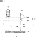
- FIG. 4 and FIG. 5 are views for describing the method of superimposing the guide lines in the first embodiment of the present invention.
- FIG. 4 and FIG. 5 illustrate an exemplary scene in which the subject vehicle travels backward to enter a parking space. The following description will be made on the assumption that the position on the image at which the distance from the subject vehicle (camera 1) is a distance represented by each distance guide line Q2 is a reference position Q2' for the distance guide line Q2.
- the position of the vehicle at which the image is captured is a position at the delay time before, which is different from the current position of the subject vehicle.
- the image illustrated in FIG. 5 is captured at a time t10.
- the image captured at the time t10 is displayed on the display 30 of the terminal device 100 at a time t11 because the wireless communication is delayed.
- the actual position of the subject vehicle is a position P1 at the traveling direction side of the vehicle than a position P0 at which the image displayed on the display 30 is captured.
- a distance d2 from the actual position P1 of the subject vehicle to the obstacle O at the time t 11 is shorter than a distance d1 from the position P0 at which the image displayed on the display 30 is captured to the obstacle O. That is, when the wireless communication is delayed, the subject vehicle is closer to the obstacle O than the position at which the image displayed on the display 30 is captured.
- the control device 10 uses the guide line superimposition function to display each distance guide line Q2 such that the distance guide line Q2 is superimposed on the image at a position at the subject vehicle side (opposite side to the traveling direction of the subject vehicle) than the reference position Q2' at which the distance from the subject vehicle (camera 1) is a distance represented by the distance guide line Q2.
- the guide lines include a plurality of distance guide lines Q2 and each distance guide line Q2 is therefore displayed such that the distance guide line Q2 is superimposed at a position at the subject vehicle side than the reference position Q2' for the distance guide line Q2.
- P3 represents a reference position Q2' (e.g. a position that represents a distance of 1.0 m from the subject vehicle) for the distance guide line Q2 in the image captured at the time t10.
- the image captured at the time t10 is displayed at the time t11 and, therefore, the position in the image at which the distance from the subject vehicle is a distance represented by the distance guide line Q2 is the position P3.
- the control device 10 uses the guide line superimposition function to display the distance guide line Q2 such that the distance guide line Q2 is superimposed at a position P4 at the subject vehicle side than the position P3.
- the distance guide line Q2 is made closer to the subject vehicle on the image, as illustrated in FIG. 5 , by a distance in which the subject vehicle actually travels with respect to the image capturing position.
- the distance represented by the distance guide line Q2 e.g. 1.0 m from the subject vehicle
- the driver can recognize the distance from the subject vehicle to the position represented by the distance guide line Q2 (e.g.
- the control device 10 uses the guide line superimposition function to estimate a traveling amount from the position at which the image is captured to the current position of the subject vehicle on the basis of the state information, such as a vehicle speed and steering information of the subject vehicle, and the delay time of the wireless communication.
- Each distance guide line Q2 is thus displayed such that the distance guide line Q2 is superimposed at the position at the subject vehicle side than the reference position Q2' by an amount corresponding to the estimated traveling amount.
- the control device 10 uses the guide line superimposition function, at the time t11, to estimate a traveling amount from the position P0 at which the image is captured to the current position P1 of the subject vehicle.
- the control device 10 uses the guide line superimposition function to display each distance guide line Q2 such that the distance guide line Q2 is superimposed at the position P4 which is shifted from the reference position Q2' toward the subject vehicle side by an amount corresponding to the estimated traveling amount.
- the control device 10 may use the guide line superimposition function to display each distance guide line Q2 such that the distance guide line Q2 is superimposed at a position at the subject vehicle side than the reference position Q2' by a predetermined traveling amount.
- the control device 10 uses the information presentation function to control the display 30 to display an image on which the guide lines are superimposed using the guide line superimposition function.
- FIG. 5 illustrates the reference positions Q2' for descriptive purposes, but when the image is displayed on the display 30, the reference positions Q2' are not displayed (the same applies to FIGS. 7 and 9 , which will be described later).
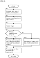
- FIG. 6 is a flowchart illustrating the information presentation process according to the first embodiment.
- the information presentation process illustrated in FIG. 6 is executed by the control device 10 of the terminal device 100.
- step S101 the control device 10 uses the delay state determination function to make a determination as to the delay state of the wireless communication between the terminal device 100 and the onboard device 200. Specifically, the control device 10 uses the delay state determination function to determine whether or not the wireless communication is established between the terminal device 100 and the onboard device 200 and, when the wireless communication is established, determine a delay time of the wireless communication. In one or more embodiments of the present invention, when the wireless communication is not established (when the wireless communication is disrupted), the control device 10 may use the information presentation function to display this fact on the display 30.
- step S102 the control device 10 uses the guide line superimposition function to acquire the state information of the subject vehicle.
- the control device 10 can use the guide line superimposition function to acquire the state information, such as a vehicle speed, acceleration, steering angle, and traveling direction of the subject vehicle, from the vehicle controller 3.
- step S103 the control device 10 uses the image acquisition function to acquire an image around the subject vehicle captured by a camera 1. Then, in step S104, the control device 10 uses the guide line superimposition function to determine whether or not the wireless communication between the terminal device 100 and the onboard device 200 is delayed, on the basis of the determination result in step S101 of the delay state of the wireless communication.
- step S104 the control device 10 uses the guide line superimposition function to determine whether or not the wireless communication between the terminal device 100 and the onboard device 200 is delayed, on the basis of the determination result in step S101 of the delay state of the wireless communication.
- the routine proceeds to step S105 while when the wireless communication is not delayed, the routine proceeds to step S106.
- a determination may be made that the wireless communication is not delayed, and the routine may proceed to step S106.
- step S106 the control device 10 uses the guide line superimposition function to perform a process of superimposing the guide lines on the image acquired in step S103.
- the determination is already made that the wireless communication is not delayed and, therefore, in step S106, the control device 10 uses the guide line superimposition function to display each distance guide line Q2, which represents a distance from the subject vehicle, such that the distance guide line Q2 is superimposed at a position (reference position Q2') at which the distance from the subject vehicle is a distance represented by the distance guide line Q2.
- step S104 the routine proceeds to step S105.
- step S105 the control device 10 uses the guide line superimposition function to display each distance guide line Q2 such that the distance guide line Q2 is superimposed on the image at a position at the subject vehicle side (opposite side to the traveling direction of the subject vehicle) than the reference position Q2' at which the distance from the subject vehicle is a distance represented by the distance guide line Q2.
- the control device 10 uses the guide line superimposition function to estimate a traveling amount from the position at which the image is captured to the current position of the subject vehicle on the basis of the determination result in step S101 of the delay state of the wireless communication and the state (e.g.
- step S102 display each distance guide line Q2 such that the distance guide line Q2 is superimposed at the position which is shifted from the reference position Q2' toward the subject vehicle side by an amount corresponding to the estimated traveling amount.
- step S107 the control device 10 uses the information presentation function to present the image, on which the guide lines are superimposed in step S105 or step S106, on the screen of the display 30.
- the information presentation system 1000 determines positions for superimposing the distance guide lines Q2 on the image captured by the camera 1, on the basis of the delay state of the wireless communication. This allows the driver to recognize the real time state around the vehicle on the image even when the wireless communication between the terminal device 100 and the onboard device 200 is delayed.
- each distance guide lines Q2 is superimposed on the image, as illustrated in FIG. 5 , at a position at the subject vehicle side (opposite side to the traveling direction of the subject vehicle) than the reference position Q2' at which the distance from the subject vehicle is a distance represented by the distance guide line Q2.
- a traveling amount of the subject vehicle during the delay time is estimated on the basis of the state (such as a vehicle speed and steering angle) of the subject vehicle and the delay time and each distance guide line Q2 is displayed such that the distance guide line Q2 is superimposed at the position which is shifted from the reference position Q2' toward the subject vehicle side by an amount corresponding to the estimated traveling amount.
- the distance guide line Q2 is made closer to the subject vehicle on the image by a distance in which the subject vehicle actually travels with respect to the image capturing position.
- the driver can therefore recognize the distance from the subject vehicle to the position represented by the distance guide line Q2 (e.g. a distance of 1.0 m from the subject vehicle) as if the distance is relatively short as compared with the case in which the distance guide line Q2 is superimposed at the reference position Q2' and displayed. Consequently, when the obstacle O exists in the traveling direction of the subject vehicle, for example, the driver can recognize the distance from the subject vehicle to the obstacle O as if the distance is a relatively short distance.
- the information presentation system 1000 according to the second embodiment has the same configuration as that of the information presentation system 1000 according to the first embodiment and performs similar operations to those of the information presentation system 1000 according to the first embodiment except that the information presentation system 1000 according to the second embodiment operates as described below.
- control device 10 of the terminal device 100 further has a moving object detection information acquisition function of detecting a moving object in addition to the functions according to the first embodiment.
- the control device 10 uses the moving object detection information acquisition function to acquire detection information as to whether or not a moving object exists around the subject vehicle. Specifically, the control device 10 uses the moving object detection information acquisition function to acquire the information as to whether or not a moving object exists from the onboard device 200.
- the onboard device 200 includes a moving object detection device 43.
- the moving object detection device 43 determines whether or not a moving object exists around the vehicle, on the basis of a variation with time of features that are extracted from images captured by the camera or cameras 1.
- the scheme of detecting a moving object on the basis of the captured images is not particularly limited and a scheme known at the time of filing the present application can be appropriately utilized.
- the control device 10 uses the guide line superimposition function to determine whether or not detection information that a moving object exists is acquired by the moving object detection information acquisition function.
- the control device 10 uses the guide line superimposition function to change positions of guide lines to be superimposed on the captured image, on the basis of a distance to the moving object.
- the control device 10 uses the guide line superimposition function to first calculate a distance from the subject vehicle (camera 1) to the moving object. Then, the control device 10 uses the guide line superimposition function to determine whether or not the moving object exists within a range of the guide lines, on the basis of the calculated distance to the moving object. For example, the control device 10 according to the present embodiment uses the guide line superimposition function to display distance guide lines Q2 such that, as illustrated in FIG. 7 , the distance guide lines Q2 are superimposed at positions at which respective distances from the subject vehicle (camera 1) are 0.5 m, 1.0 m, 2.0 m, and 3.0 m.
- the distance guide lines Q2 represent distances up to 3.0 m from the subject vehicle and the range of guide lines is thus a distance range of 3.0 m from the subject vehicle.
- the control device 10 uses the guide line superimposition function to determine that the moving object exists outside the range of guide lines.
- the control device 10 uses the guide line superimposition function to determine that the moving object exists within the range of guide lines.
- the control device 10 uses the guide line superimposition function to display each distance guide line Q2 such that, as illustrated in FIG. 7 , the distance guide line Q2 is superimposed at a position at the traveling direction side of the subject vehicle than the reference position Q2' at which the distance from the subject vehicle is a distance represented by the distance guide line Q2.
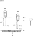
- FIG. 8 exemplifies a scene in which the subject vehicle travels backward and the image captured at a time t20 is presented to the driver at a time t21 because the wireless communication is delayed.
- the image captured at a position P10 is presented to the driver.
- the position at which the distance from the subject vehicle is a distance (e.g. 1.0 m from the subject vehicle) represented by the distance guide line Q2 is P13 on the image, the position at which the actual distance from the subject vehicle is a distance (e.g. 1.0 m from the subject vehicle) represented by the distance guide line Q2 is P14.
- the control device 10 uses the guide line superimposition function to display the distance guide line Q2 such that the distance guide line Q2 is superimposed at the position P14 at the traveling direction side of the subject vehicle than the position P13 as the reference position Q2'.
- the control device 10 can use the guide line superimposition function to estimate the current position of the subject vehicle on the basis of the delay time of the wireless communication and/or the state of the subject vehicle and display each distance guide line Q2 such that the distance guide line Q2 is superimposed at a position at which the distance from the estimated current position is a distance represented by the distance guide line Q2.
- FIG. 7 and FIG. 8 are views for describing a method of superimposing guide lines when no moving object exists around the subject vehicle or a moving object exists within the range of guide lines.
- the control device 10 uses the guide line superimposition function to display each distance guide line Q2 such that, as illustrated in FIG. 9 , the distance guide line Q2 is superimposed at a position at the subject vehicle side (opposite side to the traveling direction of the subject vehicle) than the reference position Q2'.
- FIG. 9 is a view for describing a method of superimposing guide lines when a moving object exists outside the range of guide lines.
- the control device 10 uses the guide line superimposition function to display a marker M indicative of the moving object such that, as illustrated in FIG. 9 , the marker M is superimposed on the image.
- the control device 10 uses the guide line superimposition function to display the marker M indicative of a moving object such that the marker M is superimposed at a position at the subject vehicle side than the actual position of the moving object.
- control device 10 uses the guide line superimposition function to estimate a traveling amount of the subject vehicle from the position at which the image is captured to the current position of the subject vehicle on the basis of the state information of the subject vehicle and the delay time of the wireless communication and display the marker M indicative of the moving object such that the marker M is superimposed at a position that is shifted from the actual position of the moving object toward the subject vehicle side by an amount corresponding to the estimated traveling amount. This allows the actual distance from the subject vehicle to the moving object to be displayed on the image even when the wireless communication is delayed.
- FIG. 10 is a flowchart illustrating the information presentation process according to the second embodiment.
- the information presentation process illustrated in FIG. 10 is executed by the control device 10 of the terminal device 100.
- steps S201 to S203 as in steps S101 to S103 of the first embodiment, the delay state of the wireless communication between the terminal device 100 and the onboard device 200 is determined (step S201), the state information of the subject vehicle is acquired (step S202), and the image around the subject vehicle is acquired (step S203).
- step S204 the control device 10 uses the moving object detection information acquisition function to acquire the moving object detection information. Then, in step S205, the control device 10 uses the guide line superimposition function to determine whether or not a moving object exists around the subject vehicle, on the basis of the moving object detection information acquired in step S204. When no moving object exists around the subject vehicle, the routine proceeds to step S211 while when a moving object exists around the subject vehicle, the routine proceeds to step S206.
- step S206 the control device 10 uses the guide line superimposition function to determine whether or not the moving object exists within the range of guide lines.
- the routine proceeds to step S207 while when the moving object exists outside the range of guide lines, the routine proceeds to step S208.
- step S207 a determination is already made that the moving object exists within the range of guide lines, and the control device 10 therefore uses the guide line superimposition function to display each distance guide line Q2 such that, as illustrated in FIG. 7 , the distance guide line Q2 is superimposed at a position at the traveling direction side of the subject vehicle than the reference position Q2', on the basis of the state information of the subject vehicle, such as a vehicle speed and steering angle, and the delay time of the wireless communication. This allows the actual distance from the subject vehicle to the moving object to be appropriately displayed on the image.
- step S208 a determination is already made that the moving object exists outside the range of guide lines, and the control device 10 therefore uses the guide line superimposition function to display each distance guide line Q2 such that, as illustrated in FIG. 9 , the distance guide line Q2 is superimposed at a position at the subject vehicle side (opposite side to the traveling direction of the subject vehicle) than the reference position Q2', on the basis of the state information of the subject vehicle, such as a vehicle speed and steering angle, and the delay time of the wireless communication.
- the state information of the subject vehicle such as a vehicle speed and steering angle, and the delay time of the wireless communication.
- step S209 the control device 10 uses the guide line superimposition function to perform a process of superimposing a marker indicative of the moving object on the image.
- the control device 10 uses the guide line superimposition function to display a marker M indicative of the moving object such that, as illustrated in FIG. 9 , the marker M is superimposed at a position at the subject vehicle side than the actual position of the moving object, on the basis of the state information of the subject vehicle, such as a vehicle speed and steering angle, and the delay time of the wireless communication.
- step S210 the control device 10 uses the information presentation function to present the image, on which the guide lines are superimposed in step S207 or S208 and the marker M indicative of the moving object is superimposed in step S209, on the screen of the display 30.
- step S211 when, in step S205, a determination is made that no moving object exists around the subject vehicle, the routine proceeds to step S211.
- step S211 as in step S207, in order that each distance guide line Q2 represents the actual distance from the subject vehicle, the control device 10 uses the guide line superimposition function to display the distance guide line Q2 such that the distance guide line Q2 is superimposed at a position at the traveling direction side of the subject vehicle than the reference position Q2'. This allows the actual distance from the subject vehicle to be appropriately displayed on the image.
- step S110 in which the image on which the guide lines are superimposed in step S211 is presented on the screen of the display 30.
- the information presentation system 1000 determines whether or not the moving object exists within the range of guide lines.
- the distance guide line Q2 is displayed such that, as illustrated in FIG. 7 , the distance guide line Q2 is superimposed at a position at the traveling direction side of the subject vehicle than the reference position Q2', on the basis of the state of the subject vehicle and the delay time.
- each distance guide line Q2 is displayed such that, as illustrated in FIG. 9 , the distance guide line Q2 is superimposed at a position at the subject vehicle side (opposite side to the traveling direction of the subject vehicle) than the reference position Q2'. This allows the driver to appropriately recognize that a time and a space remain with some margin until the subject vehicle comes close to the moving object as compared with the case of displaying the distance guide line Q2 such that the distance guide line Q2 is superimposed at the reference position Q2'.
- each distance guide line Q2 represents the actual distance from the subject vehicle
- the distance guide line Q2 is displayed such that, as illustrated in FIG. 7 , the distance guide line Q2 is superimposed at a position at the traveling direction side of the subject vehicle than the reference position Q2'.
- a marker M indicative of the moving object is displayed such that, as illustrated in FIG. 9 , the marker M is superimposed at a position at the subject vehicle side than the actual position of the moving object.
- each distance guide line Q2 can be displayed such that, as in the first embodiment, the distance guide line Q2 is superimposed at the reference position Q2' at which the distance from the subject vehicle is a distance represented by the distance guide line Q2 (the same applies to the third embodiment, which will be described below).
- the information presentation system 1000 according to the third embodiment has the same configuration as that of the information presentation system 1000 according to the first embodiment and performs similar operations to those of the information presentation system 1000 according to the first embodiment except that the information presentation system 1000 according to the third embodiment operates as described below.
- the control device 10 uses the delay state determination function, as in the first embodiment, to determine a delay state of the wireless communication between the terminal device 100 and the onboard device 200. In the third embodiment, the control device 10 uses the delay state determination function to determine a delay state of the wireless communication from among a communication disruption state, a normal delay state, and an abnormal delay state.
- the control device 10 uses the delay state determination function to determine that the delay state of the wireless communication is in the normal delay state.
- the control device 10 uses the delay state determination function to determine that the delay state of the wireless communication is in the abnormal delay state.
- the control device 10 uses the delay state determination function to determine that the delay state of the wireless communication is in the communication disruption state.
- the control device 10 uses the guide line superimposition function to change the display mode for guide lines on the basis of the delay state of the wireless communication between the terminal device 100 and the onboard device 200. Specifically, the control device 10 uses the guide line superimposition function to change the display mode for guide lines in accordance with the delay state of the wireless communication (communication disruption state, normal delay state, or abnormal delay state) so that the driver can recognize which state of the communication disruption state, normal delay state, and abnormal delay state the delay state of the wireless communication is in.
- FIGS. 11 to 13 are views for describing display modes for guide lines in the third embodiment.
- the control device 10 uses the guide line superimposition function to display each distance guide line Q2 such that, as illustrated in FIG. 11 , the distance guide line Q2 is superimposed at a position at the traveling direction side of the subject vehicle than the reference position Q2'.
- the control device 10 uses the guide line superimposition function to display the guide lines in a dimmed color as compared with the normal delay state or display the guide lines as broken lines, as illustrated in FIG. 12 .
- This allows the driver to appropriately recognize that the wireless communication between the terminal device 100 and the onboard device 200 is in the abnormal delay state.
- the wireless communication is delayed and the control device 10 therefore uses the guide line superimposition function to display each distance guide line Q2 such that, as in the scene illustrated in FIG. 11 , the distance guide line Q2 is superimposed at a position at the traveling direction side of the subject vehicle than the reference position Q2'.
- the control device 10 uses the guide line superimposition function to first display the guide lines in an emphasized manner than the normal delay state, as illustrated in part (A) of FIG. 13 .
- the control device 10 can use the guide line superimposition function to display the guide lines in a deeper color than the normal delay state or display the guide lines as bold lines, thereby to display the guide lines in an emphasized manner than the normal delay state.
- the control device 10 uses the guide line superimposition function to hide the guide lines, as illustrated in part (B) of FIG. 13 .
- each distance guide line Q2 can be displayed such that, as in the scenes illustrated in FIGS. 11 and 12 , the distance guide line Q2 is superimposed at a position at the traveling direction side of the subject vehicle than the reference position Q2'.
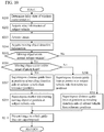
- FIG. 14 is a flowchart illustrating the information presentation process according to the third embodiment.
- the information presentation process illustrated in FIG. 14 is executed by the control device 10 of the terminal device 100.
- steps S301 to S303 as in steps S101 to S103 of the first embodiment, the delay state of the wireless communication between the terminal device 100 and the onboard device 200 is determined (step S301), the state information of the subject vehicle is acquired (step S302), and the image around the subject vehicle is acquired (step S303).
- step S301 a determination is made which state of the communication disruption state, normal delay state, and abnormal delay state the delay state of the wireless communication is in.
- step S304 the control device 10 uses the guide line superimposition function to determine whether or not the delay state of the wireless communication between the terminal device 100 and the onboard device 200 is in the communication disruption state, on the basis of the determination result in step S301.
- the routine proceeds to step S308 while when a determination is made that the delay state is not in the communication disruption state, the routine proceeds to step S305.
- step S305 the control device 10 uses the guide line superimposition function to determine whether or not the delay state of the wireless communication is in the normal delay state. For example, when the delay time of the wireless communication is a certain period of time or shorter and a determination is made that the delay state is in the normal delay state, the routine proceeds to step S306 while when the delay time of the wireless communication is longer than the certain period of time and a determination is made that the delay state is in the abnormal delay state, the routine proceeds to step S307.
- step S306 a determination is already made that the delay state of the wireless communication is in the normal delay state and the control device 10 therefore uses the guide line superimposition function to display each distance guide line Q2 such that, as illustrated in FIG. 11 , the distance guide line Q2 is superimposed at a position at the traveling direction side of the subject vehicle than the reference position Q2'.
- step S307 a determination is already made that the wireless communication is delayed and the control device 10 therefore uses the guide line superimposition function to display each distance guide line Q2 such that, as illustrated in FIG. 12 , the distance guide line Q2 is superimposed at a position at the traveling direction side of the subject vehicle than the reference position Q2'.
- step S307 a determination is already made that the delay state of the wireless communication is in the abnormal delay state and the control device 10 therefore uses the guide line superimposition function to display the guide lines in a dimmed color as compared with the case of normal delay state and display the guide lines as broken lines. This allows the driver to appropriately recognize that delay state of the wireless communication is in the abnormal delay state.
- step S304 a determination is made that the delay state of the wireless communication is in the communication disruption state
- the routine proceeds to step S308.
- step S308 the control device 10 uses the guide line superimposition function to display the guide lines in an emphasized manner, as illustrated in part (A) of FIG. 13 , and each distance guide line Q2 is displayed such that the distance guide line Q2 is superimposed at a position at the traveling direction side of the subject vehicle than the reference position Q2'.
- Step S308 is followed by step S309 in which the control device 10 uses the guide line superimposition function to determine whether or not a certain period of time passes after the guide lines are displayed in an emphasized manner.
- the routine waits in step S309 until the certain period of time passes, and proceeds to step S310 when the certain period of time passes.
- step S310 the control device 10 uses the guide line superimposition function to hide the guide lines.
- step S311 the control device 10 uses the information presentation function to display the image, on which the guide lines are superimposed in step S306, S307, or S308, on the screen of the display 30.
- the information presentation system 1000 changes the display mode for guide lines on the basis of the delay state of the wireless communication between the terminal device 100 and the onboard device 200. For example, when the delay state of the wireless communication is in the abnormal delay state, the guide lines are displayed in a specific form, such as in a dimmed color and as broken lines, as compared with the case of the normal delay state. When the delay state of the wireless communication is in the communication disruption state, the guide lines are displayed in an emphasized manner as compared with the normal delay state and then hidden.
- the present invention has been described with reference to the information presentation system 1000 comprising the terminal device 100, which comprises the control device 10 including the CPU 11, ROM 12, and RAM 13, and the onboard device 200, but the present invention is not limited to this.
- the onboard device 200 which comprises the cameras 1, the communication device 2, the vehicle controller 3, and the modules 4, but the present invention is not limited to this.
- the guide lines are displayed so as to be superimposed on a back view image captured behind the subject vehicle, but the present invention is not limited to these examples.
- the guide lines can be displayed so as to be superimposed on a front view image captured ahead of the subject vehicle or a sideward view image captured at a side of the subject vehicle.
- a projection image may be generated by projecting a plurality of images captured by a plurality of cameras 1 onto a projection plane in which the subject vehicle is viewed from a virtual viewpoint above the subject vehicle, and the guide lines can be displayed so as to be superimposed on the projection image.
- each guide line can be displayed such that the guide line is superimposed at a position at the subject vehicle side than the reference position Q2' or a position at the traveling direction side of the subject vehicle than the reference position Q2'.
- each distance guide line Q2 is displayed such that the distance guide line Q2 is superimposed at either of a position at the subject vehicle side than the reference position Q2' and a position at the traveling direction side of the subject vehicle than the reference position Q2', but the present invention is not limited to these examples.
- part of the distance guide lines Q2 can be displayed so as to be each superimposed at a position at the subject vehicle side than the reference position Q2' and the other distance guide lines Q2 can be displayed so as to be each superimposed at a position at the traveling direction side of the subject vehicle than the reference position Q2'.
- distance guide lines Q2 that represent distances within a certain distance from the subject vehicle, they can be displayed so as to be each superimposed at a position at the subject vehicle side than the reference position Q2' while, with regard to distance guide lines Q2 that represent distances beyond the certain distance from the subject vehicle, they can be displayed so as to be each superimposed at a position at the traveling direction side of the subject vehicle than the reference position Q2'.
- the guide lines which include the vehicle width guide lines Q1 and the distance guide lines Q2, are displayed so as to be superimposed on the image.
- a predicted route line P can be displayed so as to be further superimposed on the image.
- the predicted route lime P represents a trajectory on which the subject vehicle is predicted to travel.
- each distance guide line Q2 is displayed such that, as illustrated in FIG. 5 , the distance guide line Q2 is superimposed at a position at the subject vehicle side than the reference position Q2', but the present invention is not limited to this example.
- each distance guide line Q2 can be displayed such that, as illustrated in FIG. 7 , for example, the distance guide line Q2 is superimposed at a position at the traveling direction side of the subject vehicle side than the reference position Q2'. In this case, the driver can be allowed to recognize the actual distance from the subject vehicle on the image.
- each distance guide lines Q2 represents the actual distance from the subject vehicle
- the distance guide line Q2 is displayed so as to be superimposed at a position at the traveling direction side of the subject vehicle side than the reference position Q2'
- the present invention is not limited to this example.
- the distance guide lines Q2 may be displayed so as to be superimposed at a position that does not correspond to the actual distance from the subject vehicle (e.g.
- the distance represented by the distance guide line Q2 can be presented to the driver as a distance closer to the actual distance from the subject vehicle.
- the display mode for guide lines is changed on the basis of the delay state of the wireless communication
- the display mode for guide lines corresponding to each delay state is not limited to the above-described examples and can be appropriately set.
- the transparency of guide lines may be changed or the guide lines may be displayed to blink on and off.
- the transparency of guide lines can be increased or the guide lines can be displayed to blink on and off.
- the communication state of the wireless communication is in the communication disruption state, the transparency of guide lines may be first reduced and then increased.
- the guide lines may be displayed to blink on and off instead of hiding the guide lines.
- the guide lines may be displayed as lines of a retreating color, such as blue, green and blue-violet, which is relatively not distinguishable, broken lines, and/or relatively narrow lines
- the guide lines may be displayed as lines of an advancing color, such as red, orange and yellow, which is relatively distinguishable, solid lines, and/or relatively wide lines.
- positions for superimposing the distance guide lines Q2 can be determined as in the above embodiments on the basis of a determination as to whether an obstacle exists around the subject vehicle, a determination as to whether the obstacle exists within the range of guide lines, and/or other determination.
- the image acquisition function corresponds to the image acquisition device of the present invention
- the guide line superimposition function corresponds to the vehicle information acquisition device and superimposition device of the present invention
- the delay state determination function corresponds to the determination device of the present invention
- the moving object detection information acquisition function corresponds to the obstacle information acquisition device of the present invention.
Landscapes
- Engineering & Computer Science (AREA)
- Multimedia (AREA)
- Signal Processing (AREA)
- Mechanical Engineering (AREA)
- Remote Sensing (AREA)
- Radar, Positioning & Navigation (AREA)
- Theoretical Computer Science (AREA)
- General Physics & Mathematics (AREA)
- Physics & Mathematics (AREA)
- Traffic Control Systems (AREA)
- Closed-Circuit Television Systems (AREA)
- Image Processing (AREA)
- Image Analysis (AREA)
- Studio Devices (AREA)
Abstract
Description
- The present invention relates to an information presentation system that presents information regarding video footage (video image) around a vehicle.
- With regard to this kind of device, a drive assist device is known which displays video footage captured behind a vehicle when the shift lever of the vehicle is operated to the reverse position (Patent Document 1).
- [Patent Document 1]
JP2012-0162130A - However, when a portable terminal device that is not incorporated in an onboard device acquires, via wireless communication, an image captured by an onboard camera and presents the captured image, a delay in the wireless communication may cause a problem in that the timing of presenting the captured image becomes delayed.
- A problem to be solved by the present invention is to allow the terminal device to appropriately present image information that represents a real-time state around the vehicle even when a delay occurs in the wireless communication between the onboard device and the terminal device.
- The present invention solves the above problem in a manner as below. When the wireless communication is not delayed, a distance marker that represents a distance from the vehicle is superimposed on an image at a reference position at which the distance from the vehicle is a distance represented by the distance marker. When the wireless communication is delayed, the distance marker is superimposed on the image at a position at a traveling direction side of the vehicle than the reference position or a position at the vehicle side than the reference position.
- According to the present invention, when the wireless communication is delayed, the distance marker is superimposed at a position at the traveling direction side of the vehicle than the reference position or a position at the vehicle side than the reference position. The driver can therefore be allowed to recognize a real time state around the vehicle even when the wireless communication between an onboard device and a terminal device is delayed.
-
-
FIG. 1 is a block diagram of an information presentation system according to an embodiment of the present invention. -
FIG. 2 is a view illustrating an example of an image displayed on a display of a terminal device ofFIG. 1 . -
FIG. 3 is a chart for describing a delay in wireless communication. -
FIG. 4 is a view for describing a method of superimposing guide lines according to a first embodiment of the present invention. -
FIG. 5 is a view for describing the method of superimposing guide lines according to the first embodiment of the present invention. -
FIG. 6 is a flowchart illustrating an information presentation process according to the first embodiment of the present invention. -
FIG. 7 is a view for describing a method of superimposing guide lines when no moving object exists around a subject vehicle or a moving object exists within a range of guide lines in a second embodiment of the present invention. -
FIG. 8 is a view for describing the method of superimposing guide lines when no moving object exists around the subject vehicle or a moving object exists within the range of guide lines in the second embodiment of the present invention. -
FIG. 9 is a view for describing a method of superimposing guide lines when a moving object exists outside the range of guide lines in the second embodiment of the present invention. -
FIG. 10 is a flowchart illustrating an information presentation process according to the second embodiment of the present invention. -
FIG. 11 is a view for describing a display mode for guide lines in a third embodiment of the present invention when the wireless communication is in a normal delay state. -
FIG. 12 is a view for describing a display mode for guide lines in the third embodiment of the present invention when the wireless communication is in an abnormal delay state. -
FIG. 13 is a view for describing a display mode for guide lines in the third embodiment of the present invention when the wireless communication is in a communication disruption state. -
FIG. 14 is a flowchart illustrating an information presentation process according to the third embodiment of the present invention. - Hereinafter, embodiments of the present invention will be described with reference to the drawings. The embodiments will be described by exemplifying a case in which the present invention is applied to an
information presentation system 1000 comprising anonboard device 200 that has one or more cameras provided on a vehicle and aportable terminal device 100 that is in wireless communication with theonboard device 200. -
FIG. 1 is a block diagram of theinformation presentation system 1000 according to the present embodiment. Theinformation presentation system 1000 comprises theonboard device 200 and theterminal device 100. - First, the
onboard device 200 of the present embodiment will be described with reference toFIG. 1 . Theonboard device 200 comprises one or more cameras 1a to 1d, acommunication device 2, avehicle controller 3, and various types of devices 4 equipped on the vehicle (also referred to as "modules 4" in a collective term). - The one or more cameras 1a to 1d (also referred to as a "
camera 1" or "cameras 1" in a collective term, here and hereinafter) are configured using imaging elements, such as charge coupled devices (CCD). In the present embodiment, these cameras include acamera 1 that is disposed at a predetermined position of a rear (rearward) portion of the vehicle, such as a rear finisher portion and roof spoiler portion. Thiscamera 1 captures images of an object or road surface that exists in a space behind the vehicle (rearview or back view images). The term "behind the vehicle" as used herein encompasses not only the meaning of "just behind the vehicle," but also the meaning of "diagonally backward right of the vehicle" and "diagonally backward left of the vehicle." In particular, theonboard device 200 of the present embodiment includes a plurality of cameras 1a to 1d that are disposed at different positions outside the vehicle. More specifically, theonboard device 200 of the present embodiment includes cameras 1a to 1d that are each provided at a predetermined frontward position of the vehicle such as a front grille portion, at a predetermined left-side position of the vehicle such as a left-side mirror portion, or at a predetermined right-side position of the vehicle such as a right-side mirror portion. Eachcamera 1 captures video footage in a different direction around the vehicle. In the present embodiment, wide-angle cameras capable of imaging wide-angle images are used as thecameras 1. - The
onboard device 200 transmits the images captured by thecameras 1 to theterminal device 100, which will be described later. In an alternative embodiment, at least one of thecameras 1 may have a wireless communication function to transmit the captured images to external. Theterminal device 100 acquires the images captured by thecameras 1, via a wireless communication network. An image captured by eachcamera 1 is assigned with an identifier corresponding to the location (address) of thecamera 1 and theterminal device 100 can identify each of the images captured by thecamera 1, on the basis of the identifier. An image captured by eachcamera 1 is recorded with the time of capturing the image and theterminal device 100 can perceive the time of capturing each of the images captured by thecamera 1. - The
vehicle controller 3 acquires information from each module of the vehicle and comprehensively manages the operation of the vehicle. Thevehicle controller 3 of the present embodiment acquires state information that represents a state of the vehicle. Thevehicle controller 3 acquires steering information from asteering control device 41 of the vehicle as the state information, acquires acceleration information or speed information from anacceleration sensor 42 as the state information, and acquires shift position information of a transmission 44 of the vehicle as the state information. Thevehicle controller 3 transmits the acquired steering information and/or acceleration information (or speed information) to theterminal device 100. Theterminal device 100 includes acontrol device 10 which acquires a traveling direction (traveling angle) of the vehicle from the steering information. Thecontrol device 10 also acquires a traveling direction that represents whether the vehicle is traveling forward or backward from the shift position information. Thecontrol device 10 further acquires a traveling amount of the vehicle from the acceleration information (or speed information) and a traveling time. Thus, thecontrol device 10 can obtain a position of the vehicle after a predetermined time passes, from the traveling direction and traveling amount of the vehicle. - The
cameras 1,communication device 2,vehicle controller 3, and modules 4 of theonboard device 200 are connected with one another via a controller area network (CAN) or other onboard LAN and can mutually exchange information. - Next, the
terminal device 100 will be described with reference toFIG. 1 . Theterminal device 100 of the present embodiment is a portable terminal device, such as a smart-phone and tablet computer, which has a communication function. Theterminal device 100 of the present embodiment comprises acontrol device 10, acommunication device 20, and adisplay 30. - The
communication device 20 of the present embodiment exchanges information mutually with thecommunication device 2 of theonboard device 200 separated from theterminal device 100. Thecommunication device 20 acquires the captured images, information about the state of the vehicle, and other information from theonboard device 200. - The
display 30 of the present embodiment displays the images captured by thecameras 1 and information about a delay state of the wireless communication.FIG. 2 is a view illustrating an example of an image displayed on thedisplay 30 of theterminal device 100. Specifically,FIG. 2 illustrates an image (back view image) in which an object and road surface existing in the space behind the vehicle are imaged by acamera 1 that is disposed at a predetermined position of a rear (rearward) portion of the vehicle (the same applies toFIGS. 5 ,7 ,9 , and11 to 13 ). - As illustrated in
FIG. 2 , the image displayed on thedisplay 30 is displayed together with guide lines that are along a trajectory on which the vehicle is predicted to travel. For example, the guide lines are displayed so as to be superimposed on the image. The guide lines superimposed on the image include vehicle width guide lines Q1 and distance guide lines Q2. Each distance guide line Q2 is a guide line that represents a distance from the subject vehicle (camera 1). In the present embodiment, the distance guide lines Q2 are superimposed at positions of 0.5 m, 1.0 m, 2.0 m, and 3.0 m from the subject vehicle. The distances represented by the distance guide lines Q2 are not limited to 0.5 m, 1.0 m, 2.0 m, and 3.0 m and can be appropriately set. In one or more embodiments of the present invention, theterminal device 100 can be placed in a holder attached to the instrument panel or in the vicinity of the steering of the vehicle so that the driver of the vehicle can easily recognize theterminal device 100. - The
control device 10 of theterminal device 100 of the present embodiment comprises a read only memory (ROM) 12 that stores a program for superimposing the guide lines on the image captured by thecamera 1 and displaying them on thedisplay 30, a central processing unit (CPU) 11 as an operation circuit that executes the program stored in theROM 12 thereby to function as theterminal device 100 of the present embodiment, and a random access memory (RAM) 13 that functions as an accessible storage. - The
control device 10 of theterminal device 100 of the present embodiment has an image acquisition function of acquiring images captured by thecameras 1, a delay state determination function of determining a delay state of the wireless communication between theterminal device 100 and theonboard device 200, a guide line superimposition function of superimposing guide lines on an image captured by acamera 1, and an information presentation function of displaying the image, on which the guide lines are superimposed, on a display. Thecontrol device 10 is a computer that executes the above functions by cooperation of software for achieving each function and the above-described hardware. Each function achieved by thecontrol device 10 will be described below. - The
control device 10 uses the image acquisition function to acquire one or more images around the vehicle captured by theonboard cameras 1 from theonboard device 200 via thecommunication device 20. In the present embodiment, thecontrol device 10 acquires one or more back view images behind the vehicle, but the present invention is not limited to this. In addition or alternatively, thecontrol device 10 may acquire one or more front view images or sideward view images. In one or more embodiments of the present invention, thecontrol device 10 may acquire a monitoring image around the subject vehicle which is generated by theonboard device 200 and in which the subject vehicle is viewed from a virtual viewpoint above the vehicle. The monitoring image is an overhead image generated by projecting a plurality of images, which are captured by thecameras 1 disposed at different positions on the subject vehicle, onto a projection plane in which the subject vehicle is viewed from a virtual viewpoint above the vehicle. Thecontrol device 10 uses the acquired captured images and/or monitoring image as information to be presented on thedisplay 30 in a specific situation, such as when parking the subject vehicle and reversing the subject vehicle. - The
control device 10 uses the delay state determination function to determine a delay state of the wireless communication between theonboard device 200 and theterminal device 100. The delay state of the wireless communication includes a delay time of the wireless communication. For example, thecontrol device 10 uses the delay state determination function to obtain a difference between the time of capturing the image appended to the image acquired from theonboard device 200 and the time of acquiring the image, as the delay time. In one or more embodiments of the present invention, thecontrol device 10 can use the delay state determination function to determine that the delay state of the wireless communication is in a communication disruption state when the wireless communication cannot be established between theterminal device 100 and theonboard device 200. - The
control device 10 can also use the delay state determination function to obtain the delay time from a difference between a reference communication time under a predetermined good communication environment and an actually measured communication time under a communication environment in which the transmission and reception are actually performed. Although not particularly limited, thecontrol device 10 can use the delay state determination function to calculate the delay time through referring to aclock 45 of theonboard device 200 and aclock 112 of theterminal device 100 to synchronize them with each other and then measuring the actual communication time required for information to be exchanged between theonboard device 200 and theterminal device 100 via the wireless communication. Specifically, theonboard device 200 transmits information to which the transmission timing is appended, to theterminal device 100. When acquiring the information, theterminal device 100 returns acknowledgement information to theonboard device 200. Theonboard device 200 calculates half the time from the transmission timing when transmitting the information to theterminal device 100 to the reception timing when receiving the acknowledgement information transmitted from theterminal device 100, as the communication time required for the wireless communication. Similarly, the reference communication time can be calculated as a communication time for the wireless communication under a predetermined communication environment without communication load. The actually measured communication time varies from moment to moment in accordance with various factors, such as the number of terminal devices accessing the wireless communication line network and the volume of information to be exchanged. Thecontrol device 10 therefore uses the delay state determination function to acquire the communication time at a predetermined period and continuously calculates the delay time which is the difference from the reference communication time. According to the present embodiment, an accurate delay time can be calculated because the delay time is calculated after preliminarily synchronizing theonboard device 200 and theterminal device 100 with each other. - The delay time includes a regular time that is preliminarily determined in accordance with the capability of the communication facilities and a variable time that is caused by various factors, such as the communication volume. The regular time can be preliminarily stored in the
onboard device 200 or theterminal device 100. In view of reducing the processing load, the regular delay time stored may be read out to determine the delay state. - Causes of occurrence of the delay state in presenting the image captured by the
cameras 1 are not only the previously-described delay time of the wireless communication. The causes of the delay state include, as illustrated inFIG. 3 , the first to third time periods as described below which are required to complete some processes from an image capturing process to an image presentation process. The first time period as referred to herein is a time from t0 to t1 during which theonboard device 200 performs a process to capture an image around the vehicle and a process to compress the image. The second time period is a time from t1 to t2 which is required for the wireless communication. The third time period is a time from t2 to t3 which is required for a process to decompress the compressed image and a process to present the decompressed image on thedisplay 30. Thus, the delay state of the wireless communication occurs when a long period of time is taken for the processes performed at theonboard device 200 side from the time of capturing an image to the time of transmitting the image, for the communication between theonboard device 200 and theterminal device 100, and/or for the processes performed at theterminal device 100 side from the time of receiving the image to the time of presenting the image. - According to the communication technique at the time of filing the present application, when no delay occurs in the wireless communication, a time required to complete the presentation process for an image after the image capturing process is about 100 to 500 milliseconds. Even during such a short period of time, it is not preferred that the past image information is presented as if it is image information captured in real time. It is particularly undesirable if the communication delay occurs to prolong the time from the image capturing to the image presentation. When the image is transmitted and received using an internal communication network (such as CAN) in the
onboard device 200, the time from the image capturing to the image presentation is substantially constant and can therefore be controlled uniformly. In contrast, when the image obtained at theonboard device 200 side is transmitted to theterminal device 100 via public wireless communication and presented using thedisplay 30 of theterminal device 100, the delay of communication may have to be taken into consideration. In addition, the above-described third time period is highly dependent on the processing ability of theterminal device 100 and it is therefore difficult to uniformly define the delay time for theterminal device 100 which is individually and personally owned and has different performance and status. - With regard to the above-described second time period, the
control device 10 uses the delay state determination function to measure the delay time of the wireless communication between theterminal device 100 and theonboard device 200 using the above scheme. - With regard to the above-described third time period, the
control device 10 uses the delay state determination function for acquiring a terminal device-side processing time required for theterminal device 100 to present an image after acquiring the image, adding the terminal device-side processing time to the delay time of the wireless communication to calculate a delay time in the information presentation, and determining the delay state. Although not particularly limited, it is preferred that the terminal device-side processing time be experimentally calculated in advance and stored in theterminal device 100 in a readable manner. The delay state can be correctly determined by not only calculating the delay of the wireless communication but also calculating a delay time through addition of the time required for the processes at theterminal device 100 side. - With regard to the above-described first time period, the
control device 10 may use the delay state determination function to add, to the delay time, a time required for the processes performed at theonboard device 200 side from the time of acquisition of an image (image capturing) to the time of transmission of the image. The delay state can be further correctly determined by not only calculating the delay of the wireless communication but also calculating a delay time through addition of the time required for the processes at theonboard device 200 side. - The
control device 10 can use the delay state determination function to determine whether or not the wireless communication with thecommunication device 2 is disrupted. When the wireless communication is disrupted, thedisplay 30 can be controlled to present that the wireless communication is disrupted. In a situation in which the wireless communication with thecommunication device 2 is disrupted, it is difficult to acquire the captured image at the present moment in real time. In other words, it is highly possible that the captured image presented on thedisplay 30 is originated from past video footage. According to the present embodiment, by presenting that the wireless communication with thecommunication device 2 is disrupted, it is possible to inform the driver that the presented captured image is not a real-time image. - The
control device 10 may use the delay state determination function to determine a degree of reliability of the wireless communication in accordance with the delay state. When the delay time is long and the delay state of the wireless communication is bad, a determination is made that the degree of reliability of the wireless communication is low. On the other hand, when the delay time is short and the delay state of the wireless communication is not bad (communication state is good), a determination is made that the degree of reliability of the wireless communication is high. The degree of reliability of the wireless communication can be defined in accordance with the communication time in the communication state. As the communication time is longer, the degree of reliability of the wireless communication can be set lower. Thecontrol device 10 controls thedisplay 30 to present the determined degree of reliability. In a situation in which the delay time of the wireless communication is long and the degree of reliability of the wireless communication is low, it is difficult to acquire the captured image at the present moment in real time. In other words, it is highly possible that the captured image presented on thedisplay 30 is originated from past video footage. According to the present embodiment, by presenting that the degree of reliability of the wireless communication with thecommunication device 2 is low, it is possible to inform the driver that the presented captured image is not a real-time image. - The
control device 10 uses the guide line superimposition function to generate guide lines. The guide lines include the vehicle width guide lines Q1 which represent positions of the side surfaces of the subject vehicle when the subject vehicle travels and the distance guide lines Q2 which represent positions along the traveling direction of the subject vehicle when the subject vehicle travels. Then, thecontrol device 10 uses the guide line superimposition function to display the generated guide lines such that, as illustrated inFIG. 2 , the guide lines are superimposed on the image captured by thecamera 1. When the wireless communication between theterminal device 100 and theonboard device 200 is not delayed, thecontrol device 10 uses the guide line superimposition function to superimpose each distance guide line Q2 at a position at which the distance from the subject vehicle is a distance represented by the distance guide line Q2. - On the other hand, when the wireless communication between the
terminal device 100 and theonboard device 200 is delayed, thecontrol device 10 uses the guide line superimposition function to determine superimposition positions of the guide lines on the image on the basis of the delay state of the wireless communication and the state of the subject vehicle acquired from thevehicle controller 3. A method of superimposing the guide lines according to the first embodiment of the present invention will be described below with reference toFIG. 4 andFIG. 5 .FIG. 4 andFIG. 5 are views for describing the method of superimposing the guide lines in the first embodiment of the present invention.FIG. 4 andFIG. 5 illustrate an exemplary scene in which the subject vehicle travels backward to enter a parking space. The following description will be made on the assumption that the position on the image at which the distance from the subject vehicle (camera 1) is a distance represented by each distance guide line Q2 is a reference position Q2' for the distance guide line Q2. - When the wireless communication between the
terminal device 100 and theonboard device 200 is delayed, the position of the vehicle at which the image is captured is a position at the delay time before, which is different from the current position of the subject vehicle. For example, in the scene illustrated inFIG. 4 , it is assumed that the image illustrated inFIG. 5 is captured at a time t10. In the example illustrated inFIG. 4 , however, the image captured at the time t10 is displayed on thedisplay 30 of theterminal device 100 at a time t11 because the wireless communication is delayed. At the time t11, therefore, the actual position of the subject vehicle is a position P1 at the traveling direction side of the vehicle than a position P0 at which the image displayed on thedisplay 30 is captured. - As illustrated in
FIG. 4 , when an obstacle O (such as a wall) exists at a position P2 at the traveling direction side of the subject vehicle and the wireless communication is delayed, a distance d2 from the actual position P1 of the subject vehicle to the obstacle O at thetime t 11 is shorter than a distance d1 from the position P0 at which the image displayed on thedisplay 30 is captured to the obstacle O. That is, when the wireless communication is delayed, the subject vehicle is closer to the obstacle O than the position at which the image displayed on thedisplay 30 is captured. When the wireless communication is delayed, therefore, in order to allow the driver to recognize that the subject vehicle is closer to the obstacle O than the case of no delay of the wireless communication, thecontrol device 10 uses the guide line superimposition function to display each distance guide line Q2 such that the distance guide line Q2 is superimposed on the image at a position at the subject vehicle side (opposite side to the traveling direction of the subject vehicle) than the reference position Q2' at which the distance from the subject vehicle (camera 1) is a distance represented by the distance guide line Q2. In the present embodiment, the guide lines include a plurality of distance guide lines Q2 and each distance guide line Q2 is therefore displayed such that the distance guide line Q2 is superimposed at a position at the subject vehicle side than the reference position Q2' for the distance guide line Q2. - For example, in the example illustrated in
FIG. 4 , it is assumed that P3 represents a reference position Q2' (e.g. a position that represents a distance of 1.0 m from the subject vehicle) for the distance guide line Q2 in the image captured at the time t10. In this case, the image captured at the time t10 is displayed at the time t11 and, therefore, the position in the image at which the distance from the subject vehicle is a distance represented by the distance guide line Q2 is the position P3. Nevertheless, in such a case, thecontrol device 10 uses the guide line superimposition function to display the distance guide line Q2 such that the distance guide line Q2 is superimposed at a position P4 at the subject vehicle side than the position P3. This allows the position P4, at which the distance guide line Q2 is superimposed and displayed on the image displayed by thedisplay 30, to be a position nearer to the subject vehicle than the position P3 which is the reference position Q2'. Thus, in the present embodiment, the distance guide line Q2 is made closer to the subject vehicle on the image, as illustrated inFIG. 5 , by a distance in which the subject vehicle actually travels with respect to the image capturing position. Through this operation, the distance represented by the distance guide line Q2 (e.g. 1.0 m from the subject vehicle) is not changed, but the driver can recognize the distance from the subject vehicle to the position represented by the distance guide line Q2 (e.g. a distance of 1.0 m from the subject vehicle) as if the distance is relatively shortened as compared with the case in which the distance guide line Q2 is superimposed at the reference position Q2' and displayed. Consequently, when the obstacle O exists in the traveling direction of the subject vehicle, for example, the driver can recognize the distance from the subject vehicle to the obstacle O as if the distance is a relatively short distance. - When the wireless communication is delayed, the
control device 10 uses the guide line superimposition function to estimate a traveling amount from the position at which the image is captured to the current position of the subject vehicle on the basis of the state information, such as a vehicle speed and steering information of the subject vehicle, and the delay time of the wireless communication. Each distance guide line Q2 is thus displayed such that the distance guide line Q2 is superimposed at the position at the subject vehicle side than the reference position Q2' by an amount corresponding to the estimated traveling amount. For example, in the example illustrated inFIG. 4 , thecontrol device 10 uses the guide line superimposition function, at the time t11, to estimate a traveling amount from the position P0 at which the image is captured to the current position P1 of the subject vehicle. Then, thecontrol device 10 uses the guide line superimposition function to display each distance guide line Q2 such that the distance guide line Q2 is superimposed at the position P4 which is shifted from the reference position Q2' toward the subject vehicle side by an amount corresponding to the estimated traveling amount. In an alternative embodiment, thecontrol device 10 may use the guide line superimposition function to display each distance guide line Q2 such that the distance guide line Q2 is superimposed at a position at the subject vehicle side than the reference position Q2' by a predetermined traveling amount. - As illustrated in
FIG. 5 , for example, thecontrol device 10 uses the information presentation function to control thedisplay 30 to display an image on which the guide lines are superimposed using the guide line superimposition function.FIG. 5 illustrates the reference positions Q2' for descriptive purposes, but when the image is displayed on thedisplay 30, the reference positions Q2' are not displayed (the same applies toFIGS. 7 and9 , which will be described later). - Next, the information presentation process according to the first embodiment will be described.
FIG. 6 is a flowchart illustrating the information presentation process according to the first embodiment. The information presentation process illustrated inFIG. 6 is executed by thecontrol device 10 of theterminal device 100. - In step S101, the
control device 10 uses the delay state determination function to make a determination as to the delay state of the wireless communication between theterminal device 100 and theonboard device 200. Specifically, thecontrol device 10 uses the delay state determination function to determine whether or not the wireless communication is established between theterminal device 100 and theonboard device 200 and, when the wireless communication is established, determine a delay time of the wireless communication. In one or more embodiments of the present invention, when the wireless communication is not established (when the wireless communication is disrupted), thecontrol device 10 may use the information presentation function to display this fact on thedisplay 30. - In step S102, the
control device 10 uses the guide line superimposition function to acquire the state information of the subject vehicle. For example, thecontrol device 10 can use the guide line superimposition function to acquire the state information, such as a vehicle speed, acceleration, steering angle, and traveling direction of the subject vehicle, from thevehicle controller 3. - In step S103, the
control device 10 uses the image acquisition function to acquire an image around the subject vehicle captured by acamera 1. Then, in step S104, thecontrol device 10 uses the guide line superimposition function to determine whether or not the wireless communication between theterminal device 100 and theonboard device 200 is delayed, on the basis of the determination result in step S101 of the delay state of the wireless communication. When the wireless communication is delayed, the routine proceeds to step S105 while when the wireless communication is not delayed, the routine proceeds to step S106. In one or more embodiments of the present invention, when the wireless communication is merely delayed for a certain period of time (e.g. 200 msec) or less, a determination may be made that the wireless communication is not delayed, and the routine may proceed to step S106. - In step S106, the
control device 10 uses the guide line superimposition function to perform a process of superimposing the guide lines on the image acquired in step S103. The determination is already made that the wireless communication is not delayed and, therefore, in step S106, thecontrol device 10 uses the guide line superimposition function to display each distance guide line Q2, which represents a distance from the subject vehicle, such that the distance guide line Q2 is superimposed at a position (reference position Q2') at which the distance from the subject vehicle is a distance represented by the distance guide line Q2. - When a determination is made in step S104 that the wireless communication is delayed, the routine proceeds to step S105. In step S105, the
control device 10 uses the guide line superimposition function to display each distance guide line Q2 such that the distance guide line Q2 is superimposed on the image at a position at the subject vehicle side (opposite side to the traveling direction of the subject vehicle) than the reference position Q2' at which the distance from the subject vehicle is a distance represented by the distance guide line Q2. For example, thecontrol device 10 uses the guide line superimposition function to estimate a traveling amount from the position at which the image is captured to the current position of the subject vehicle on the basis of the determination result in step S101 of the delay state of the wireless communication and the state (e.g. vehicle speed and steering angle) of the subject vehicle acquired in step S102 and display each distance guide line Q2 such that the distance guide line Q2 is superimposed at the position which is shifted from the reference position Q2' toward the subject vehicle side by an amount corresponding to the estimated traveling amount. - Then, in step S107, the
control device 10 uses the information presentation function to present the image, on which the guide lines are superimposed in step S105 or step S106, on the screen of thedisplay 30. - As described above, the
information presentation system 1000 according to the first embodiment determines positions for superimposing the distance guide lines Q2 on the image captured by thecamera 1, on the basis of the delay state of the wireless communication. This allows the driver to recognize the real time state around the vehicle on the image even when the wireless communication between theterminal device 100 and theonboard device 200 is delayed. - This will be more specifically described. In the present embodiment, when the wireless communication is delayed, each distance guide lines Q2 is superimposed on the image, as illustrated in
FIG. 5 , at a position at the subject vehicle side (opposite side to the traveling direction of the subject vehicle) than the reference position Q2' at which the distance from the subject vehicle is a distance represented by the distance guide line Q2. Moreover, a traveling amount of the subject vehicle during the delay time is estimated on the basis of the state (such as a vehicle speed and steering angle) of the subject vehicle and the delay time and each distance guide line Q2 is displayed such that the distance guide line Q2 is superimposed at the position which is shifted from the reference position Q2' toward the subject vehicle side by an amount corresponding to the estimated traveling amount. Thus, in the present embodiment, the distance guide line Q2 is made closer to the subject vehicle on the image by a distance in which the subject vehicle actually travels with respect to the image capturing position. The driver can therefore recognize the distance from the subject vehicle to the position represented by the distance guide line Q2 (e.g. a distance of 1.0 m from the subject vehicle) as if the distance is relatively short as compared with the case in which the distance guide line Q2 is superimposed at the reference position Q2' and displayed. Consequently, when the obstacle O exists in the traveling direction of the subject vehicle, for example, the driver can recognize the distance from the subject vehicle to the obstacle O as if the distance is a relatively short distance. - Next, an
information presentation system 1000 according to a second embodiment of the present invention will be described. Theinformation presentation system 1000 according to the second embodiment has the same configuration as that of theinformation presentation system 1000 according to the first embodiment and performs similar operations to those of theinformation presentation system 1000 according to the first embodiment except that theinformation presentation system 1000 according to the second embodiment operates as described below. - In the second embodiment, the
control device 10 of theterminal device 100 further has a moving object detection information acquisition function of detecting a moving object in addition to the functions according to the first embodiment. - The
control device 10 uses the moving object detection information acquisition function to acquire detection information as to whether or not a moving object exists around the subject vehicle. Specifically, thecontrol device 10 uses the moving object detection information acquisition function to acquire the information as to whether or not a moving object exists from theonboard device 200. Theonboard device 200 includes a moving object detection device 43. The moving object detection device 43 determines whether or not a moving object exists around the vehicle, on the basis of a variation with time of features that are extracted from images captured by the camera orcameras 1. The scheme of detecting a moving object on the basis of the captured images is not particularly limited and a scheme known at the time of filing the present application can be appropriately utilized. - In the second embodiment, when the wireless communication is delayed, the
control device 10 uses the guide line superimposition function to determine whether or not detection information that a moving object exists is acquired by the moving object detection information acquisition function. When a moving object exists, thecontrol device 10 uses the guide line superimposition function to change positions of guide lines to be superimposed on the captured image, on the basis of a distance to the moving object. - Specifically, when a moving object exists around the subject vehicle, the
control device 10 uses the guide line superimposition function to first calculate a distance from the subject vehicle (camera 1) to the moving object. Then, thecontrol device 10 uses the guide line superimposition function to determine whether or not the moving object exists within a range of the guide lines, on the basis of the calculated distance to the moving object. For example, thecontrol device 10 according to the present embodiment uses the guide line superimposition function to display distance guide lines Q2 such that, as illustrated inFIG. 7 , the distance guide lines Q2 are superimposed at positions at which respective distances from the subject vehicle (camera 1) are 0.5 m, 1.0 m, 2.0 m, and 3.0 m. In this case, the distance guide lines Q2 represent distances up to 3.0 m from the subject vehicle and the range of guide lines is thus a distance range of 3.0 m from the subject vehicle. When the distance from the subject vehicle to the moving object exceeds 3.0 m, therefore, thecontrol device 10 uses the guide line superimposition function to determine that the moving object exists outside the range of guide lines. When the distance from the subject vehicle to the moving object is 3.0 m or less, thecontrol device 10 uses the guide line superimposition function to determine that the moving object exists within the range of guide lines. - Then, when no moving object exists around the subject vehicle or a moving object exists within the range of guide lines, the
control device 10 uses the guide line superimposition function to display each distance guide line Q2 such that, as illustrated inFIG. 7 , the distance guide line Q2 is superimposed at a position at the traveling direction side of the subject vehicle than the reference position Q2' at which the distance from the subject vehicle is a distance represented by the distance guide line Q2. Here,FIG. 8 exemplifies a scene in which the subject vehicle travels backward and the image captured at a time t20 is presented to the driver at a time t21 because the wireless communication is delayed. In this case, when the subject vehicle travels to a position P11 at the time t21, the image captured at a position P10 is presented to the driver. At the time t21, therefore, even though the position at which the distance from the subject vehicle is a distance (e.g. 1.0 m from the subject vehicle) represented by the distance guide line Q2 is P13 on the image, the position at which the actual distance from the subject vehicle is a distance (e.g. 1.0 m from the subject vehicle) represented by the distance guide line Q2 is P14. Accordingly, when no moving object exists around the subject vehicle or a moving object exists within the range of guide lines, in order that each distance guide line Q2 in the image represents an actual distance from the subject vehicle, thecontrol device 10 uses the guide line superimposition function to display the distance guide line Q2 such that the distance guide line Q2 is superimposed at the position P14 at the traveling direction side of the subject vehicle than the position P13 as the reference position Q2'. In this case, thecontrol device 10 can use the guide line superimposition function to estimate the current position of the subject vehicle on the basis of the delay time of the wireless communication and/or the state of the subject vehicle and display each distance guide line Q2 such that the distance guide line Q2 is superimposed at a position at which the distance from the estimated current position is a distance represented by the distance guide line Q2. This allows each distance guide line Q2 to be displayed so as to represent the actual distance from the subject vehicle.FIG. 7 andFIG. 8 are views for describing a method of superimposing guide lines when no moving object exists around the subject vehicle or a moving object exists within the range of guide lines. - On the other hand, when a moving object exists outside the range of guide lines, the
control device 10 uses the guide line superimposition function to display each distance guide line Q2 such that, as illustrated inFIG. 9 , the distance guide line Q2 is superimposed at a position at the subject vehicle side (opposite side to the traveling direction of the subject vehicle) than the reference position Q2'. This allows the driver to recognize that a time and a space remain with some margin until the subject vehicle comes close to the moving object as compared with the case of superimposing the distance guide line Q2 at the reference position Q2'.FIG. 9 is a view for describing a method of superimposing guide lines when a moving object exists outside the range of guide lines. - When a moving object exists around the subject vehicle, the
control device 10 uses the guide line superimposition function to display a marker M indicative of the moving object such that, as illustrated inFIG. 9 , the marker M is superimposed on the image. When the wireless communication is delayed, thecontrol device 10 uses the guide line superimposition function to display the marker M indicative of a moving object such that the marker M is superimposed at a position at the subject vehicle side than the actual position of the moving object. Specifically, thecontrol device 10 uses the guide line superimposition function to estimate a traveling amount of the subject vehicle from the position at which the image is captured to the current position of the subject vehicle on the basis of the state information of the subject vehicle and the delay time of the wireless communication and display the marker M indicative of the moving object such that the marker M is superimposed at a position that is shifted from the actual position of the moving object toward the subject vehicle side by an amount corresponding to the estimated traveling amount. This allows the actual distance from the subject vehicle to the moving object to be displayed on the image even when the wireless communication is delayed. - Next, the information presentation process according to the second embodiment will be described.
FIG. 10 is a flowchart illustrating the information presentation process according to the second embodiment. The information presentation process illustrated inFIG. 10 is executed by thecontrol device 10 of theterminal device 100. - In steps S201 to S203, as in steps S101 to S103 of the first embodiment, the delay state of the wireless communication between the
terminal device 100 and theonboard device 200 is determined (step S201), the state information of the subject vehicle is acquired (step S202), and the image around the subject vehicle is acquired (step S203). - In step S204, the
control device 10 uses the moving object detection information acquisition function to acquire the moving object detection information. Then, in step S205, thecontrol device 10 uses the guide line superimposition function to determine whether or not a moving object exists around the subject vehicle, on the basis of the moving object detection information acquired in step S204. When no moving object exists around the subject vehicle, the routine proceeds to step S211 while when a moving object exists around the subject vehicle, the routine proceeds to step S206. - In step S206, the
control device 10 uses the guide line superimposition function to determine whether or not the moving object exists within the range of guide lines. When the moving object exists within the range of guide lines, the routine proceeds to step S207 while when the moving object exists outside the range of guide lines, the routine proceeds to step S208. - In step S207, a determination is already made that the moving object exists within the range of guide lines, and the
control device 10 therefore uses the guide line superimposition function to display each distance guide line Q2 such that, as illustrated inFIG. 7 , the distance guide line Q2 is superimposed at a position at the traveling direction side of the subject vehicle than the reference position Q2', on the basis of the state information of the subject vehicle, such as a vehicle speed and steering angle, and the delay time of the wireless communication. This allows the actual distance from the subject vehicle to the moving object to be appropriately displayed on the image. - In step S208, a determination is already made that the moving object exists outside the range of guide lines, and the
control device 10 therefore uses the guide line superimposition function to display each distance guide line Q2 such that, as illustrated inFIG. 9 , the distance guide line Q2 is superimposed at a position at the subject vehicle side (opposite side to the traveling direction of the subject vehicle) than the reference position Q2', on the basis of the state information of the subject vehicle, such as a vehicle speed and steering angle, and the delay time of the wireless communication. This allows the driver to appropriately recognize that a time and a space remain with some margin until the subject vehicle comes close to the moving object as compared with the case of superimposing the distance guide line Q2 at the reference position Q2'. - In step S209, the
control device 10 uses the guide line superimposition function to perform a process of superimposing a marker indicative of the moving object on the image. Specifically, thecontrol device 10 uses the guide line superimposition function to display a marker M indicative of the moving object such that, as illustrated inFIG. 9 , the marker M is superimposed at a position at the subject vehicle side than the actual position of the moving object, on the basis of the state information of the subject vehicle, such as a vehicle speed and steering angle, and the delay time of the wireless communication. - Then, in step S210, the
control device 10 uses the information presentation function to present the image, on which the guide lines are superimposed in step S207 or S208 and the marker M indicative of the moving object is superimposed in step S209, on the screen of thedisplay 30. - When, in step S205, a determination is made that no moving object exists around the subject vehicle, the routine proceeds to step S211. In step S211, as in step S207, in order that each distance guide line Q2 represents the actual distance from the subject vehicle, the
control device 10 uses the guide line superimposition function to display the distance guide line Q2 such that the distance guide line Q2 is superimposed at a position at the traveling direction side of the subject vehicle than the reference position Q2'. This allows the actual distance from the subject vehicle to be appropriately displayed on the image. Then, the routine proceeds to step S110, in which the image on which the guide lines are superimposed in step S211 is presented on the screen of thedisplay 30. - As described above, when the wireless communication is delayed and a moving object is detected, the
information presentation system 1000 according to the second embodiment determines whether or not the moving object exists within the range of guide lines. When the moving object exists within the range of guide lines, in order that each distance guide line Q2 represents the actual distance from the subject vehicle, the distance guide line Q2 is displayed such that, as illustrated inFIG. 7 , the distance guide line Q2 is superimposed at a position at the traveling direction side of the subject vehicle than the reference position Q2', on the basis of the state of the subject vehicle and the delay time. Through this operation, according to the second embodiment, the driver can appropriately recognize the actual distance from the subject vehicle to the moving object even when the wireless communication is delayed. - Moreover, in the second embodiment, when the wireless communication is delayed and a moving object exists outside the range of guide lines, each distance guide line Q2 is displayed such that, as illustrated in
FIG. 9 , the distance guide line Q2 is superimposed at a position at the subject vehicle side (opposite side to the traveling direction of the subject vehicle) than the reference position Q2'. This allows the driver to appropriately recognize that a time and a space remain with some margin until the subject vehicle comes close to the moving object as compared with the case of displaying the distance guide line Q2 such that the distance guide line Q2 is superimposed at the reference position Q2'. - Furthermore, in the second embodiment, when the wireless communication is delayed and a moving object does not exist around the subject vehicle, in order that each distance guide line Q2 represents the actual distance from the subject vehicle, the distance guide line Q2 is displayed such that, as illustrated in
FIG. 7 , the distance guide line Q2 is superimposed at a position at the traveling direction side of the subject vehicle than the reference position Q2'. Through this operation, when the wireless communication is delayed and a moving object does not exist around the subject vehicle, the actual distance from the subject vehicle can be appropriately displayed on the image using the distance guide lines Q2. - In addition, in the second embodiment, when the wireless communication is delayed and a moving object exists around the subject vehicle, a marker M indicative of the moving object is displayed such that, as illustrated in
FIG. 9 , the marker M is superimposed at a position at the subject vehicle side than the actual position of the moving object. Through this operation, even when the wireless communication is delayed, the actual distance from the subject vehicle to the moving object can be appropriately displayed on the image. - As will be understood, when the wireless communication is not delayed in the second embodiment, each distance guide line Q2 can be displayed such that, as in the first embodiment, the distance guide line Q2 is superimposed at the reference position Q2' at which the distance from the subject vehicle is a distance represented by the distance guide line Q2 (the same applies to the third embodiment, which will be described below).
- Next, an
information presentation system 1000 according to a third embodiment of the present invention will be described. Theinformation presentation system 1000 according to the third embodiment has the same configuration as that of theinformation presentation system 1000 according to the first embodiment and performs similar operations to those of theinformation presentation system 1000 according to the first embodiment except that theinformation presentation system 1000 according to the third embodiment operates as described below. - In the third embodiment, the
control device 10 uses the delay state determination function, as in the first embodiment, to determine a delay state of the wireless communication between theterminal device 100 and theonboard device 200. In the third embodiment, thecontrol device 10 uses the delay state determination function to determine a delay state of the wireless communication from among a communication disruption state, a normal delay state, and an abnormal delay state. - Specifically, when the delay time of the wireless communication is a predetermined period of time (e.g. 200 msec) or shorter, the
control device 10 uses the delay state determination function to determine that the delay state of the wireless communication is in the normal delay state. When the delay time of the wireless communication is longer than the predetermined period of time, thecontrol device 10 uses the delay state determination function to determine that the delay state of the wireless communication is in the abnormal delay state. When the wireless communication cannot be established between theterminal device 100 and theonboard device 200, thecontrol device 10 uses the delay state determination function to determine that the delay state of the wireless communication is in the communication disruption state. - In the third embodiment, the
control device 10 uses the guide line superimposition function to change the display mode for guide lines on the basis of the delay state of the wireless communication between theterminal device 100 and theonboard device 200. Specifically, thecontrol device 10 uses the guide line superimposition function to change the display mode for guide lines in accordance with the delay state of the wireless communication (communication disruption state, normal delay state, or abnormal delay state) so that the driver can recognize which state of the communication disruption state, normal delay state, and abnormal delay state the delay state of the wireless communication is in. Here,FIGS. 11 to 13 are views for describing display modes for guide lines in the third embodiment. - For example, when a determination is made that the delay state of the wireless communication is in the normal delay state, the
control device 10 uses the guide line superimposition function to display each distance guide line Q2 such that, as illustrated inFIG. 11 , the distance guide line Q2 is superimposed at a position at the traveling direction side of the subject vehicle than the reference position Q2'. - When a determination is made that the delay state of the wireless communication is in the abnormal delay state, the
control device 10 uses the guide line superimposition function to display the guide lines in a dimmed color as compared with the normal delay state or display the guide lines as broken lines, as illustrated inFIG. 12 . This allows the driver to appropriately recognize that the wireless communication between theterminal device 100 and theonboard device 200 is in the abnormal delay state. In the scene illustrated inFIG. 12 , the wireless communication is delayed and thecontrol device 10 therefore uses the guide line superimposition function to display each distance guide line Q2 such that, as in the scene illustrated inFIG. 11 , the distance guide line Q2 is superimposed at a position at the traveling direction side of the subject vehicle than the reference position Q2'. - When a determination is made that the delay state of the wireless communication is in the communication disruption state, the
control device 10 uses the guide line superimposition function to first display the guide lines in an emphasized manner than the normal delay state, as illustrated in part (A) ofFIG. 13 . For example, thecontrol device 10 can use the guide line superimposition function to display the guide lines in a deeper color than the normal delay state or display the guide lines as bold lines, thereby to display the guide lines in an emphasized manner than the normal delay state. Then, after a certain period of time passes from the emphasized display of guide lines, thecontrol device 10 uses the guide line superimposition function to hide the guide lines, as illustrated in part (B) ofFIG. 13 . This allows the driver to appropriately recognize that the wireless communication between theterminal device 100 and theonboard device 200 is in the communication disruption state. Also in the scene illustrated inFIG. 13 , when the distance guide lines Q2 are displayed in an emphasized manner, each distance guide line Q2 can be displayed such that, as in the scenes illustrated inFIGS. 11 and12 , the distance guide line Q2 is superimposed at a position at the traveling direction side of the subject vehicle than the reference position Q2'. - Next, the information presentation process according to the third embodiment will be described.
FIG. 14 is a flowchart illustrating the information presentation process according to the third embodiment. The information presentation process illustrated inFIG. 14 is executed by thecontrol device 10 of theterminal device 100. - In steps S301 to S303, as in steps S101 to S103 of the first embodiment, the delay state of the wireless communication between the
terminal device 100 and theonboard device 200 is determined (step S301), the state information of the subject vehicle is acquired (step S302), and the image around the subject vehicle is acquired (step S303). In step S301, a determination is made which state of the communication disruption state, normal delay state, and abnormal delay state the delay state of the wireless communication is in. - In step S304, the
control device 10 uses the guide line superimposition function to determine whether or not the delay state of the wireless communication between theterminal device 100 and theonboard device 200 is in the communication disruption state, on the basis of the determination result in step S301. When a determination is made that the delay state is in the communication disruption state, the routine proceeds to step S308 while when a determination is made that the delay state is not in the communication disruption state, the routine proceeds to step S305. - In step S305, the
control device 10 uses the guide line superimposition function to determine whether or not the delay state of the wireless communication is in the normal delay state. For example, when the delay time of the wireless communication is a certain period of time or shorter and a determination is made that the delay state is in the normal delay state, the routine proceeds to step S306 while when the delay time of the wireless communication is longer than the certain period of time and a determination is made that the delay state is in the abnormal delay state, the routine proceeds to step S307. - In step S306, a determination is already made that the delay state of the wireless communication is in the normal delay state and the
control device 10 therefore uses the guide line superimposition function to display each distance guide line Q2 such that, as illustrated inFIG. 11 , the distance guide line Q2 is superimposed at a position at the traveling direction side of the subject vehicle than the reference position Q2'. - Also in step S307, a determination is already made that the wireless communication is delayed and the
control device 10 therefore uses the guide line superimposition function to display each distance guide line Q2 such that, as illustrated inFIG. 12 , the distance guide line Q2 is superimposed at a position at the traveling direction side of the subject vehicle than the reference position Q2'. In step S307, a determination is already made that the delay state of the wireless communication is in the abnormal delay state and thecontrol device 10 therefore uses the guide line superimposition function to display the guide lines in a dimmed color as compared with the case of normal delay state and display the guide lines as broken lines. This allows the driver to appropriately recognize that delay state of the wireless communication is in the abnormal delay state. - When, in step S304, a determination is made that the delay state of the wireless communication is in the communication disruption state, the routine proceeds to step S308. In step S308, the
control device 10 uses the guide line superimposition function to display the guide lines in an emphasized manner, as illustrated in part (A) ofFIG. 13 , and each distance guide line Q2 is displayed such that the distance guide line Q2 is superimposed at a position at the traveling direction side of the subject vehicle than the reference position Q2'. - Step S308 is followed by step S309 in which the
control device 10 uses the guide line superimposition function to determine whether or not a certain period of time passes after the guide lines are displayed in an emphasized manner. The routine waits in step S309 until the certain period of time passes, and proceeds to step S310 when the certain period of time passes. In step S310, thecontrol device 10 uses the guide line superimposition function to hide the guide lines. Thus, when the delay state of the wireless communication is in the communication disruption state, the guide lines are displayed in an emphasized manner and then hidden thereby to allow the driver to appropriately recognize that the delay state of the wireless communication is in the communication disruption state. - In step S311, the
control device 10 uses the information presentation function to display the image, on which the guide lines are superimposed in step S306, S307, or S308, on the screen of thedisplay 30. - As described above, the
information presentation system 1000 according to the third embodiment changes the display mode for guide lines on the basis of the delay state of the wireless communication between theterminal device 100 and theonboard device 200. For example, when the delay state of the wireless communication is in the abnormal delay state, the guide lines are displayed in a specific form, such as in a dimmed color and as broken lines, as compared with the case of the normal delay state. When the delay state of the wireless communication is in the communication disruption state, the guide lines are displayed in an emphasized manner as compared with the normal delay state and then hidden. Through this operation of the third embodiment, an effect can be obtained that the driver is allowed to appropriately recognize the delay state of the wireless communication, in addition to the effects obtained in the first embodiment. - Embodiments heretofore explained are described to facilitate understanding of the present invention and are not described to limit the present invention. It is therefore intended that the elements disclosed in the above embodiments include all design changes and equivalents to fall within the technical scope of the present invention.
- For example, in the above-described embodiments, an aspect of the information presentation system according to the present invention has been described with reference to the
terminal device 100 and theinformation presentation system 1000, but the present invention is not limited to this. - In the above-described embodiments, an aspect of the information presentation system according to the present invention has been described with reference to the
information presentation system 1000 comprising theterminal device 100, which comprises thecontrol device 10 including theCPU 11,ROM 12, andRAM 13, and theonboard device 200, but the present invention is not limited to this. - In the above-described embodiments, an aspect of the onboard device having a camera and a communication function has been described with reference to the
onboard device 200 which comprises thecameras 1, thecommunication device 2, thevehicle controller 3, and the modules 4, but the present invention is not limited to this. - In the above-described embodiments, examples have been described in which the guide lines are displayed so as to be superimposed on a back view image captured behind the subject vehicle, but the present invention is not limited to these examples. In one or more embodiments of the present invention, the guide lines can be displayed so as to be superimposed on a front view image captured ahead of the subject vehicle or a sideward view image captured at a side of the subject vehicle. In an alternative embodiment of the present invention, a projection image may be generated by projecting a plurality of images captured by a plurality of
cameras 1 onto a projection plane in which the subject vehicle is viewed from a virtual viewpoint above the subject vehicle, and the guide lines can be displayed so as to be superimposed on the projection image. Also in this case, on the basis of the vehicle speed, acceleration, and steering angle of the subject vehicle and the delay time of the wireless communication, each guide line can be displayed such that the guide line is superimposed at a position at the subject vehicle side than the reference position Q2' or a position at the traveling direction side of the subject vehicle than the reference position Q2'. - In the above-described embodiments, examples have been described in which, when the wireless communication is delayed, each distance guide line Q2 is displayed such that the distance guide line Q2 is superimposed at either of a position at the subject vehicle side than the reference position Q2' and a position at the traveling direction side of the subject vehicle than the reference position Q2', but the present invention is not limited to these examples. In one or more embodiments of the present invention, part of the distance guide lines Q2 can be displayed so as to be each superimposed at a position at the subject vehicle side than the reference position Q2' and the other distance guide lines Q2 can be displayed so as to be each superimposed at a position at the traveling direction side of the subject vehicle than the reference position Q2'. For example, with regard to distance guide lines Q2 that represent distances within a certain distance from the subject vehicle, they can be displayed so as to be each superimposed at a position at the subject vehicle side than the reference position Q2' while, with regard to distance guide lines Q2 that represent distances beyond the certain distance from the subject vehicle, they can be displayed so as to be each superimposed at a position at the traveling direction side of the subject vehicle than the reference position Q2'.
- In the above-described embodiments, examples have been described in which the guide lines, which include the vehicle width guide lines Q1 and the distance guide lines Q2, are displayed so as to be superimposed on the image. In addition to this, a predicted route line P can be displayed so as to be further superimposed on the image. The predicted route lime P represents a trajectory on which the subject vehicle is predicted to travel.
- In the above-described first embodiment, an example has been described in which, when the wireless communication is delayed, each distance guide line Q2 is displayed such that, as illustrated in
FIG. 5 , the distance guide line Q2 is superimposed at a position at the subject vehicle side than the reference position Q2', but the present invention is not limited to this example. In one or more embodiments of the present invention, each distance guide line Q2 can be displayed such that, as illustrated inFIG. 7 , for example, the distance guide line Q2 is superimposed at a position at the traveling direction side of the subject vehicle side than the reference position Q2'. In this case, the driver can be allowed to recognize the actual distance from the subject vehicle on the image. - In the above-described second embodiment, an example has been described in which, when the wireless communication is delayed and no moving object exists around the subject vehicle or a moving object exists outside the range of guide lines, in order that each distance guide lines Q2 represents the actual distance from the subject vehicle, the distance guide line Q2 is displayed so as to be superimposed at a position at the traveling direction side of the subject vehicle side than the reference position Q2', but the present invention is not limited to this example. For example, provided that each distance guide line Q2 is superimposed at a position at the traveling direction side of the subject vehicle side than the reference position Q2', the distance guide lines Q2 may be displayed so as to be superimposed at a position that does not correspond to the actual distance from the subject vehicle (e.g. a position that is shifted from the reference position Q2' toward the traveling direction side of the subject vehicle by a predetermined distance). Also in this case, the distance represented by the distance guide line Q2 can be presented to the driver as a distance closer to the actual distance from the subject vehicle.
- In the above-described third embodiment, an example has been described in which the display mode for guide lines is changed on the basis of the delay state of the wireless communication, but the display mode for guide lines corresponding to each delay state is not limited to the above-described examples and can be appropriately set. For example, in addition or alternatively to the color, width, and form (such as broken lines) of the guide lines, the transparency of guide lines may be changed or the guide lines may be displayed to blink on and off. For example, when the communication state of the wireless communication is in the abnormal delay state, the transparency of guide lines can be increased or the guide lines can be displayed to blink on and off. When the communication state of the wireless communication is in the communication disruption state, the transparency of guide lines may be first reduced and then increased. In one or more embodiments of the present invention, the guide lines may be displayed to blink on and off instead of hiding the guide lines. In the case of the normal delay state, the guide lines may be displayed as lines of a retreating color, such as blue, green and blue-violet, which is relatively not distinguishable, broken lines, and/or relatively narrow lines, while in the case of the abnormal delay state, the guide lines may be displayed as lines of an advancing color, such as red, orange and yellow, which is relatively distinguishable, solid lines, and/or relatively wide lines.
- In the above-described second embodiment, an example has been described in which a moving object existing around the subject vehicle is detected, but an obstacle (such as a wall and curbstone) existing around the subject vehicle may be detected. Also in this case, positions for superimposing the distance guide lines Q2 can be determined as in the above embodiments on the basis of a determination as to whether an obstacle exists around the subject vehicle, a determination as to whether the obstacle exists within the range of guide lines, and/or other determination.
- In the
control device 10 according to the above-described embodiments, the image acquisition function corresponds to the image acquisition device of the present invention, the guide line superimposition function corresponds to the vehicle information acquisition device and superimposition device of the present invention, the delay state determination function corresponds to the determination device of the present invention, and the moving object detection information acquisition function corresponds to the obstacle information acquisition device of the present invention. -
- 1000
- Information presentation system
100 Terminal device
10 Control device
11 CPU
12 ROM
13 RAM
20 Communication device
30 Display - 200
- Onboard device
1, 1a to 1d Camera
2 Communication device
3 Vehicle controller
4 Modules
41 Steering control device
42 Acceleration sensor
43 Moving object detection device
Claims (9)
- An information presentation system comprising:an onboard device including a camera provided on a vehicle; anda terminal device having portability and performing wireless communication with the onboard device,the terminal device being configured:to acquire an image around the vehicle captured by the camera;to superimpose a distance marker on the image, the distance marker representing a distance from the vehicle;to determine a delay state including a delay time of the wireless communication between the onboard device and the terminal device; andto present the image on which the distance marker is superimposed, wherein, when the wireless communication is not delayed, the terminal device superimposes the distance marker on the image at a reference position at which a distance from the vehicle is a distance represented by the distance marker, andwhen the wireless communication is delayed, the terminal device superimposes the distance marker on the image at a position at a traveling direction side of the vehicle than the reference position or a position at the vehicle side than the reference position.
- The information presentation system according to claim 1, wherein the terminal device acquires state information of the vehicle, estimates a traveling amount from a position of the vehicle when capturing the image to a current position of the vehicle on a basis of the state information of the vehicle and the delay time of the wireless communication, and superimposes the distance marker at a position shifted from the reference position toward the traveling direction side of the vehicle or toward the vehicle side by the traveling amount.
- The information presentation system according to claim 1, wherein the terminal device superimposes the distance marker at a position shifted from the reference position toward the traveling direction side of the vehicle or toward the vehicle side by a predetermined traveling amount.
- The information presentation system according to any one of claims 1 to 3, wherein the terminal device acquires information on an obstacle existing around the vehicle, and
the terminal device determines a position for superimposing the distance marker with reference to the information on the obstacle. - The information presentation system according to claim 4, wherein, when the wireless communication is delayed and the obstacle is not detected, the terminal device superimposes the distance marker at the traveling direction side of the vehicle than the reference position.
- The information presentation system according to claim 4 or 5, wherein, when the wireless communication is delayed and the obstacle exists within a distance range from the vehicle represented by the distance marker in the image, the terminal device superimposes the distance marker at the traveling direction side of the vehicle than the reference position.
- The information presentation system according to any one of claims 4 to 6, wherein, when the wireless communication is delayed and the obstacle exists outside a distance range from the vehicle represented by the distance marker in the image, the terminal device superimposes the distance marker at the vehicle side than the reference position.
- The information presentation system according to any one of claims 4 to 7, wherein, when the obstacle exists, the terminal device superimposes a marker representing a position of the obstacle at a position at the vehicle side than an actual position of the obstacle.
- The information presentation system according to any one of claims 1 to 8, wherein the terminal device changes a display mode for the distance marker on the image in accordance with the delay state of the wireless communication.
Applications Claiming Priority (1)
| Application Number | Priority Date | Filing Date | Title |
|---|---|---|---|
| PCT/JP2015/065532 WO2016194039A1 (en) | 2015-05-29 | 2015-05-29 | Information presentation system |
Publications (3)
| Publication Number | Publication Date |
|---|---|
| EP3306918A1 true EP3306918A1 (en) | 2018-04-11 |
| EP3306918A4 EP3306918A4 (en) | 2018-07-04 |
| EP3306918B1 EP3306918B1 (en) | 2019-10-16 |
Family
ID=57441043
Family Applications (1)
| Application Number | Title | Priority Date | Filing Date |
|---|---|---|---|
| EP15894074.2A Active EP3306918B1 (en) | 2015-05-29 | 2015-05-29 | Information presentation system |
Country Status (11)
| Country | Link |
|---|---|
| US (1) | US10144351B2 (en) |
| EP (1) | EP3306918B1 (en) |
| JP (1) | JP6451840B2 (en) |
| KR (1) | KR101874279B1 (en) |
| CN (1) | CN107615757B (en) |
| BR (1) | BR112017025525A2 (en) |
| CA (1) | CA2987558A1 (en) |
| MX (1) | MX363856B (en) |
| MY (1) | MY182014A (en) |
| RU (1) | RU2677256C1 (en) |
| WO (1) | WO2016194039A1 (en) |
Families Citing this family (14)
| Publication number | Priority date | Publication date | Assignee | Title |
|---|---|---|---|---|
| JP6358123B2 (en) * | 2015-02-16 | 2018-07-18 | 株式会社デンソー | Driving assistance device |
| JP7036501B2 (en) * | 2017-02-24 | 2022-03-15 | 株式会社デンソーテン | Charging support device and charging support method |
| DE102017130173A1 (en) * | 2017-02-24 | 2018-08-30 | Denso Ten Limited | CHARGING DEVICE SUPPORT |
| DE102017130169A1 (en) * | 2017-02-24 | 2018-08-30 | Denso Ten Limited | CHARGING DEVICE SUPPORT |
| WO2018230021A1 (en) * | 2017-06-16 | 2018-12-20 | 株式会社Jvcケンウッド | Display control device, display control system, display control method and display control program |
| US10486594B2 (en) * | 2017-09-19 | 2019-11-26 | Ford Global Technologies, Llc | Systems and methods for determining vehicle wireless camera latency |
| JP7037926B2 (en) * | 2017-12-04 | 2022-03-17 | アルパイン株式会社 | Driving support system and rear guide image generation method |
| DE102018102047A1 (en) * | 2018-01-30 | 2019-08-01 | Bayerische Motoren Werke Aktiengesellschaft | A method of representing a surrounding area of a motor vehicle with virtual, elongated distance markings in an image, computer program product, and display system |
| JP6964276B2 (en) * | 2018-03-07 | 2021-11-10 | パナソニックIpマネジメント株式会社 | Display control device, vehicle peripheral display system and computer program |
| JP7113348B2 (en) * | 2018-03-15 | 2022-08-05 | パナソニックIpマネジメント株式会社 | VEHICLE AREA DISPLAY SYSTEM, DISPLAY CONTROL DEVICE AND COMPUTER PROGRAM |
| JP7172309B2 (en) * | 2018-09-06 | 2022-11-16 | 株式会社アイシン | Perimeter monitoring device |
| US10909714B2 (en) | 2018-10-30 | 2021-02-02 | Here Global B.V. | Method, apparatus, and system for providing a distance marker in an image |
| JP7238670B2 (en) * | 2019-07-23 | 2023-03-14 | トヨタ自動車株式会社 | image display device |
| JP7131780B2 (en) * | 2019-12-19 | 2022-09-06 | 株式会社ガク・アソシエイツ | Boundary Visualization System, Boundary Visualization Method, Boundary Visualization Program, and Digital Photo Album Creation System |
Family Cites Families (19)
| Publication number | Priority date | Publication date | Assignee | Title |
|---|---|---|---|---|
| AU3522500A (en) * | 1999-03-11 | 2000-09-28 | Intelligent Technologies International, Inc. | Methods and apparatus for preventing vehicle accidents |
| JP3805702B2 (en) | 2002-03-01 | 2006-08-09 | 三菱電機株式会社 | Vehicle periphery monitoring device |
| DE102005015088B4 (en) * | 2004-04-02 | 2015-06-18 | Denso Corporation | Vehicle environment monitoring system |
| JP4661658B2 (en) | 2006-03-30 | 2011-03-30 | アイシン・エィ・ダブリュ株式会社 | Driving support method, driving support device, and driving support program |
| DE102007045562A1 (en) * | 2007-09-24 | 2009-04-02 | Robert Bosch Gmbh | Control device for a display device of a parking device and method for representation |
| JP4929114B2 (en) * | 2007-09-28 | 2012-05-09 | 日産自動車株式会社 | Vehicle information notifying device, information providing system, and information notifying method |
| JP4412380B2 (en) * | 2007-10-02 | 2010-02-10 | アイシン・エィ・ダブリュ株式会社 | Driving support device, driving support method, and computer program |
| JP2009111469A (en) * | 2007-10-26 | 2009-05-21 | Victor Co Of Japan Ltd | Video image output device and method, video image display apparatus and method |
| US8217773B2 (en) * | 2008-12-04 | 2012-07-10 | Denso Corporation | Field watch apparatus |
| JP5445218B2 (en) | 2010-02-25 | 2014-03-19 | マツダ株式会社 | Parking assistance system |
| JP2011259152A (en) | 2010-06-08 | 2011-12-22 | Suzuki Motor Corp | Driving assistance device |
| KR20120056977A (en) * | 2010-11-26 | 2012-06-05 | 주식회사 이미지넥스트 | Vehicle Loading type Blackbox System and Information Providing Method by using Surrounding Image produced from the System |
| EP2481637B1 (en) * | 2011-01-28 | 2014-05-21 | Nxp B.V. | Parking Assistance System and Method |
| JP2012162130A (en) | 2011-02-04 | 2012-08-30 | Aisin Aw Co Ltd | Driving support device, driving support method and computer program |
| JP6045796B2 (en) * | 2012-02-27 | 2016-12-14 | 京セラ株式会社 | Video processing apparatus, video processing method, and video display system |
| CN103338335B (en) * | 2013-06-19 | 2017-02-08 | 奇瑞汽车股份有限公司 | Auxiliary vehicle character superimposition device |
| JP6209921B2 (en) | 2013-09-27 | 2017-10-11 | 日産自動車株式会社 | Predictive course presentation system |
| BR112016006666B1 (en) | 2013-09-27 | 2023-04-04 | Nissan Motor Co., Ltd | INFORMATION PRESENTATION SYSTEM |
| CN104512408B (en) * | 2013-10-04 | 2017-11-21 | 本田技研工业株式会社 | Parking assist apparatus |
-
2015
- 2015-05-29 CN CN201580080520.0A patent/CN107615757B/en active Active
- 2015-05-29 JP JP2017521314A patent/JP6451840B2/en active Active
- 2015-05-29 KR KR1020177034492A patent/KR101874279B1/en not_active Expired - Fee Related
- 2015-05-29 US US15/578,119 patent/US10144351B2/en active Active
- 2015-05-29 EP EP15894074.2A patent/EP3306918B1/en active Active
- 2015-05-29 BR BR112017025525A patent/BR112017025525A2/en active Search and Examination
- 2015-05-29 WO PCT/JP2015/065532 patent/WO2016194039A1/en not_active Ceased
- 2015-05-29 MX MX2017015166A patent/MX363856B/en active IP Right Grant
- 2015-05-29 RU RU2017146056A patent/RU2677256C1/en active
- 2015-05-29 MY MYPI2017704541A patent/MY182014A/en unknown
- 2015-05-29 CA CA2987558A patent/CA2987558A1/en not_active Abandoned
Also Published As
| Publication number | Publication date |
|---|---|
| CA2987558A1 (en) | 2016-12-08 |
| MY182014A (en) | 2021-01-18 |
| CN107615757B (en) | 2018-10-09 |
| US10144351B2 (en) | 2018-12-04 |
| US20180154830A1 (en) | 2018-06-07 |
| CN107615757A (en) | 2018-01-19 |
| RU2677256C1 (en) | 2019-01-16 |
| KR20170141778A (en) | 2017-12-26 |
| BR112017025525A2 (en) | 2018-08-07 |
| MX2017015166A (en) | 2018-04-13 |
| JP6451840B2 (en) | 2019-01-16 |
| KR101874279B1 (en) | 2018-07-03 |
| WO2016194039A1 (en) | 2016-12-08 |
| EP3306918B1 (en) | 2019-10-16 |
| MX363856B (en) | 2019-04-05 |
| JPWO2016194039A1 (en) | 2018-05-31 |
| EP3306918A4 (en) | 2018-07-04 |
Similar Documents
| Publication | Publication Date | Title |
|---|---|---|
| EP3306918B1 (en) | Information presentation system | |
| EP3051808B1 (en) | Information provision system | |
| US10810446B2 (en) | Parking space line detection method and device | |
| US10183621B2 (en) | Vehicular image processing apparatus and vehicular image processing system | |
| JP4643860B2 (en) | VISUAL SUPPORT DEVICE AND SUPPORT METHOD FOR VEHICLE | |
| CN110831818B (en) | Parking assist method and parking assist device | |
| EP2045133A2 (en) | Vehicle periphery monitoring apparatus and image displaying method | |
| US20150324649A1 (en) | Method and Device for Analyzing Trafficability | |
| CN111016905A (en) | Interaction method and system for automatic driving vehicle and driving remote control terminal | |
| CN101542555A (en) | Method for wireless communication between vehicles | |
| US20200398689A1 (en) | Method and apparatus for aligning a vehicle with a wireless charging system | |
| JP2009065483A (en) | Parking assistance device | |
| JP2018005386A (en) | Travel support device, travel support method, imaging apparatus, and vehicle | |
| JP2009231937A (en) | Surroundings monitoring device for vehicle | |
| JP2008293095A (en) | Driving support system | |
| EP3951744A1 (en) | Image processing device, vehicle control device, method, and program | |
| CN111835998B (en) | Beyond-the-horizon panoramic image acquisition method, device, medium, equipment and system | |
| EP3547282A1 (en) | Attention calling display apparatus | |
| EP3829155B1 (en) | Imaging system for railway vehicle | |
| KR20190022949A (en) | System for recognizing circumstance of vehicle and method thereof | |
| JP5699926B2 (en) | Inter-vehicle communication system and in-vehicle device | |
| JP7800559B2 (en) | Video display system, video display method, and video display device | |
| JP2008059178A (en) | Driving support device and program | |
| CN119316559A (en) | Camera sharing method, device, vehicle and storage medium | |
| JP2007253781A (en) | In-vehicle display system |
Legal Events
| Date | Code | Title | Description |
|---|---|---|---|
| STAA | Information on the status of an ep patent application or granted ep patent |
Free format text: STATUS: THE INTERNATIONAL PUBLICATION HAS BEEN MADE |
|
| PUAI | Public reference made under article 153(3) epc to a published international application that has entered the european phase |
Free format text: ORIGINAL CODE: 0009012 |
|
| STAA | Information on the status of an ep patent application or granted ep patent |
Free format text: STATUS: REQUEST FOR EXAMINATION WAS MADE |
|
| 17P | Request for examination filed |
Effective date: 20171222 |
|
| AK | Designated contracting states |
Kind code of ref document: A1 Designated state(s): AL AT BE BG CH CY CZ DE DK EE ES FI FR GB GR HR HU IE IS IT LI LT LU LV MC MK MT NL NO PL PT RO RS SE SI SK SM TR |
|
| AX | Request for extension of the european patent |
Extension state: BA ME |
|
| A4 | Supplementary search report drawn up and despatched |
Effective date: 20180605 |
|
| RIC1 | Information provided on ipc code assigned before grant |
Ipc: B60R 21/00 20060101ALI20180525BHEP Ipc: H04N 7/18 20060101AFI20180525BHEP Ipc: B60R 1/00 20060101ALI20180525BHEP Ipc: H04N 5/225 20060101ALI20180525BHEP Ipc: G06T 1/00 20060101ALI20180525BHEP |
|
| DAV | Request for validation of the european patent (deleted) | ||
| DAX | Request for extension of the european patent (deleted) | ||
| STAA | Information on the status of an ep patent application or granted ep patent |
Free format text: STATUS: EXAMINATION IS IN PROGRESS |
|
| 17Q | First examination report despatched |
Effective date: 20190121 |
|
| GRAP | Despatch of communication of intention to grant a patent |
Free format text: ORIGINAL CODE: EPIDOSNIGR1 |
|
| STAA | Information on the status of an ep patent application or granted ep patent |
Free format text: STATUS: GRANT OF PATENT IS INTENDED |
|
| INTG | Intention to grant announced |
Effective date: 20190708 |
|
| GRAS | Grant fee paid |
Free format text: ORIGINAL CODE: EPIDOSNIGR3 |
|
| GRAA | (expected) grant |
Free format text: ORIGINAL CODE: 0009210 |
|
| STAA | Information on the status of an ep patent application or granted ep patent |
Free format text: STATUS: THE PATENT HAS BEEN GRANTED |
|
| AK | Designated contracting states |
Kind code of ref document: B1 Designated state(s): AL AT BE BG CH CY CZ DE DK EE ES FI FR GB GR HR HU IE IS IT LI LT LU LV MC MK MT NL NO PL PT RO RS SE SI SK SM TR |
|
| REG | Reference to a national code |
Ref country code: GB Ref legal event code: FG4D |
|
| REG | Reference to a national code |
Ref country code: CH Ref legal event code: EP |
|
| REG | Reference to a national code |
Ref country code: DE Ref legal event code: R096 Ref document number: 602015040101 Country of ref document: DE |
|
| REG | Reference to a national code |
Ref country code: IE Ref legal event code: FG4D |
|
| REG | Reference to a national code |
Ref country code: AT Ref legal event code: REF Ref document number: 1192467 Country of ref document: AT Kind code of ref document: T Effective date: 20191115 |
|
| REG | Reference to a national code |
Ref country code: NL Ref legal event code: MP Effective date: 20191016 |
|
| REG | Reference to a national code |
Ref country code: LT Ref legal event code: MG4D |
|
| REG | Reference to a national code |
Ref country code: AT Ref legal event code: MK05 Ref document number: 1192467 Country of ref document: AT Kind code of ref document: T Effective date: 20191016 |
|
| PG25 | Lapsed in a contracting state [announced via postgrant information from national office to epo] |
Ref country code: PL Free format text: LAPSE BECAUSE OF FAILURE TO SUBMIT A TRANSLATION OF THE DESCRIPTION OR TO PAY THE FEE WITHIN THE PRESCRIBED TIME-LIMIT Effective date: 20191016 Ref country code: SE Free format text: LAPSE BECAUSE OF FAILURE TO SUBMIT A TRANSLATION OF THE DESCRIPTION OR TO PAY THE FEE WITHIN THE PRESCRIBED TIME-LIMIT Effective date: 20191016 Ref country code: LT Free format text: LAPSE BECAUSE OF FAILURE TO SUBMIT A TRANSLATION OF THE DESCRIPTION OR TO PAY THE FEE WITHIN THE PRESCRIBED TIME-LIMIT Effective date: 20191016 Ref country code: BG Free format text: LAPSE BECAUSE OF FAILURE TO SUBMIT A TRANSLATION OF THE DESCRIPTION OR TO PAY THE FEE WITHIN THE PRESCRIBED TIME-LIMIT Effective date: 20200116 Ref country code: NL Free format text: LAPSE BECAUSE OF FAILURE TO SUBMIT A TRANSLATION OF THE DESCRIPTION OR TO PAY THE FEE WITHIN THE PRESCRIBED TIME-LIMIT Effective date: 20191016 Ref country code: FI Free format text: LAPSE BECAUSE OF FAILURE TO SUBMIT A TRANSLATION OF THE DESCRIPTION OR TO PAY THE FEE WITHIN THE PRESCRIBED TIME-LIMIT Effective date: 20191016 Ref country code: AT Free format text: LAPSE BECAUSE OF FAILURE TO SUBMIT A TRANSLATION OF THE DESCRIPTION OR TO PAY THE FEE WITHIN THE PRESCRIBED TIME-LIMIT Effective date: 20191016 Ref country code: PT Free format text: LAPSE BECAUSE OF FAILURE TO SUBMIT A TRANSLATION OF THE DESCRIPTION OR TO PAY THE FEE WITHIN THE PRESCRIBED TIME-LIMIT Effective date: 20200217 Ref country code: LV Free format text: LAPSE BECAUSE OF FAILURE TO SUBMIT A TRANSLATION OF THE DESCRIPTION OR TO PAY THE FEE WITHIN THE PRESCRIBED TIME-LIMIT Effective date: 20191016 Ref country code: GR Free format text: LAPSE BECAUSE OF FAILURE TO SUBMIT A TRANSLATION OF THE DESCRIPTION OR TO PAY THE FEE WITHIN THE PRESCRIBED TIME-LIMIT Effective date: 20200117 Ref country code: NO Free format text: LAPSE BECAUSE OF FAILURE TO SUBMIT A TRANSLATION OF THE DESCRIPTION OR TO PAY THE FEE WITHIN THE PRESCRIBED TIME-LIMIT Effective date: 20200116 |
|
| PG25 | Lapsed in a contracting state [announced via postgrant information from national office to epo] |
Ref country code: RS Free format text: LAPSE BECAUSE OF FAILURE TO SUBMIT A TRANSLATION OF THE DESCRIPTION OR TO PAY THE FEE WITHIN THE PRESCRIBED TIME-LIMIT Effective date: 20191016 Ref country code: HR Free format text: LAPSE BECAUSE OF FAILURE TO SUBMIT A TRANSLATION OF THE DESCRIPTION OR TO PAY THE FEE WITHIN THE PRESCRIBED TIME-LIMIT Effective date: 20191016 Ref country code: IS Free format text: LAPSE BECAUSE OF FAILURE TO SUBMIT A TRANSLATION OF THE DESCRIPTION OR TO PAY THE FEE WITHIN THE PRESCRIBED TIME-LIMIT Effective date: 20200224 |
|
| PG25 | Lapsed in a contracting state [announced via postgrant information from national office to epo] |
Ref country code: AL Free format text: LAPSE BECAUSE OF FAILURE TO SUBMIT A TRANSLATION OF THE DESCRIPTION OR TO PAY THE FEE WITHIN THE PRESCRIBED TIME-LIMIT Effective date: 20191016 |
|
| REG | Reference to a national code |
Ref country code: DE Ref legal event code: R097 Ref document number: 602015040101 Country of ref document: DE |
|
| PG2D | Information on lapse in contracting state deleted |
Ref country code: IS |
|
| PG25 | Lapsed in a contracting state [announced via postgrant information from national office to epo] |
Ref country code: CZ Free format text: LAPSE BECAUSE OF FAILURE TO SUBMIT A TRANSLATION OF THE DESCRIPTION OR TO PAY THE FEE WITHIN THE PRESCRIBED TIME-LIMIT Effective date: 20191016 Ref country code: RO Free format text: LAPSE BECAUSE OF FAILURE TO SUBMIT A TRANSLATION OF THE DESCRIPTION OR TO PAY THE FEE WITHIN THE PRESCRIBED TIME-LIMIT Effective date: 20191016 Ref country code: ES Free format text: LAPSE BECAUSE OF FAILURE TO SUBMIT A TRANSLATION OF THE DESCRIPTION OR TO PAY THE FEE WITHIN THE PRESCRIBED TIME-LIMIT Effective date: 20191016 Ref country code: EE Free format text: LAPSE BECAUSE OF FAILURE TO SUBMIT A TRANSLATION OF THE DESCRIPTION OR TO PAY THE FEE WITHIN THE PRESCRIBED TIME-LIMIT Effective date: 20191016 Ref country code: DK Free format text: LAPSE BECAUSE OF FAILURE TO SUBMIT A TRANSLATION OF THE DESCRIPTION OR TO PAY THE FEE WITHIN THE PRESCRIBED TIME-LIMIT Effective date: 20191016 Ref country code: IS Free format text: LAPSE BECAUSE OF FAILURE TO SUBMIT A TRANSLATION OF THE DESCRIPTION OR TO PAY THE FEE WITHIN THE PRESCRIBED TIME-LIMIT Effective date: 20200216 |
|
| PLBE | No opposition filed within time limit |
Free format text: ORIGINAL CODE: 0009261 |
|
| STAA | Information on the status of an ep patent application or granted ep patent |
Free format text: STATUS: NO OPPOSITION FILED WITHIN TIME LIMIT |
|
| PG25 | Lapsed in a contracting state [announced via postgrant information from national office to epo] |
Ref country code: SK Free format text: LAPSE BECAUSE OF FAILURE TO SUBMIT A TRANSLATION OF THE DESCRIPTION OR TO PAY THE FEE WITHIN THE PRESCRIBED TIME-LIMIT Effective date: 20191016 Ref country code: IT Free format text: LAPSE BECAUSE OF FAILURE TO SUBMIT A TRANSLATION OF THE DESCRIPTION OR TO PAY THE FEE WITHIN THE PRESCRIBED TIME-LIMIT Effective date: 20191016 Ref country code: SM Free format text: LAPSE BECAUSE OF FAILURE TO SUBMIT A TRANSLATION OF THE DESCRIPTION OR TO PAY THE FEE WITHIN THE PRESCRIBED TIME-LIMIT Effective date: 20191016 |
|
| 26N | No opposition filed |
Effective date: 20200717 |
|
| PG25 | Lapsed in a contracting state [announced via postgrant information from national office to epo] |
Ref country code: SI Free format text: LAPSE BECAUSE OF FAILURE TO SUBMIT A TRANSLATION OF THE DESCRIPTION OR TO PAY THE FEE WITHIN THE PRESCRIBED TIME-LIMIT Effective date: 20191016 |
|
| PG25 | Lapsed in a contracting state [announced via postgrant information from national office to epo] |
Ref country code: LI Free format text: LAPSE BECAUSE OF NON-PAYMENT OF DUE FEES Effective date: 20200531 Ref country code: MC Free format text: LAPSE BECAUSE OF FAILURE TO SUBMIT A TRANSLATION OF THE DESCRIPTION OR TO PAY THE FEE WITHIN THE PRESCRIBED TIME-LIMIT Effective date: 20191016 Ref country code: CH Free format text: LAPSE BECAUSE OF NON-PAYMENT OF DUE FEES Effective date: 20200531 |
|
| REG | Reference to a national code |
Ref country code: BE Ref legal event code: MM Effective date: 20200531 |
|
| GBPC | Gb: european patent ceased through non-payment of renewal fee |
Effective date: 20200529 |
|
| PG25 | Lapsed in a contracting state [announced via postgrant information from national office to epo] |
Ref country code: LU Free format text: LAPSE BECAUSE OF NON-PAYMENT OF DUE FEES Effective date: 20200529 |
|
| PG25 | Lapsed in a contracting state [announced via postgrant information from national office to epo] |
Ref country code: GB Free format text: LAPSE BECAUSE OF NON-PAYMENT OF DUE FEES Effective date: 20200529 Ref country code: IE Free format text: LAPSE BECAUSE OF NON-PAYMENT OF DUE FEES Effective date: 20200529 |
|
| PG25 | Lapsed in a contracting state [announced via postgrant information from national office to epo] |
Ref country code: BE Free format text: LAPSE BECAUSE OF NON-PAYMENT OF DUE FEES Effective date: 20200531 |
|
| PG25 | Lapsed in a contracting state [announced via postgrant information from national office to epo] |
Ref country code: TR Free format text: LAPSE BECAUSE OF FAILURE TO SUBMIT A TRANSLATION OF THE DESCRIPTION OR TO PAY THE FEE WITHIN THE PRESCRIBED TIME-LIMIT Effective date: 20191016 Ref country code: MT Free format text: LAPSE BECAUSE OF FAILURE TO SUBMIT A TRANSLATION OF THE DESCRIPTION OR TO PAY THE FEE WITHIN THE PRESCRIBED TIME-LIMIT Effective date: 20191016 Ref country code: CY Free format text: LAPSE BECAUSE OF FAILURE TO SUBMIT A TRANSLATION OF THE DESCRIPTION OR TO PAY THE FEE WITHIN THE PRESCRIBED TIME-LIMIT Effective date: 20191016 |
|
| PG25 | Lapsed in a contracting state [announced via postgrant information from national office to epo] |
Ref country code: MK Free format text: LAPSE BECAUSE OF FAILURE TO SUBMIT A TRANSLATION OF THE DESCRIPTION OR TO PAY THE FEE WITHIN THE PRESCRIBED TIME-LIMIT Effective date: 20191016 |
|
| REG | Reference to a national code |
Ref country code: DE Ref legal event code: R084 Ref document number: 602015040101 Country of ref document: DE |
|
| PGFP | Annual fee paid to national office [announced via postgrant information from national office to epo] |
Ref country code: DE Payment date: 20250423 Year of fee payment: 11 |
|
| PGFP | Annual fee paid to national office [announced via postgrant information from national office to epo] |
Ref country code: FR Payment date: 20250423 Year of fee payment: 11 |