EP3306871B1 - Verfahren und vorrichtung zur erfassung von weginformationen - Google Patents
Verfahren und vorrichtung zur erfassung von weginformationen Download PDFInfo
- Publication number
- EP3306871B1 EP3306871B1 EP15909101.6A EP15909101A EP3306871B1 EP 3306871 B1 EP3306871 B1 EP 3306871B1 EP 15909101 A EP15909101 A EP 15909101A EP 3306871 B1 EP3306871 B1 EP 3306871B1
- Authority
- EP
- European Patent Office
- Prior art keywords
- service packet
- target service
- packet
- field
- information
- Prior art date
- Legal status (The legal status is an assumption and is not a legal conclusion. Google has not performed a legal analysis and makes no representation as to the accuracy of the status listed.)
- Active
Links
Images





Classifications
-
- H—ELECTRICITY
- H04—ELECTRIC COMMUNICATION TECHNIQUE
- H04L—TRANSMISSION OF DIGITAL INFORMATION, e.g. TELEGRAPHIC COMMUNICATION
- H04L45/00—Routing or path finding of packets in data switching networks
- H04L45/02—Topology update or discovery
-
- H—ELECTRICITY
- H04—ELECTRIC COMMUNICATION TECHNIQUE
- H04L—TRANSMISSION OF DIGITAL INFORMATION, e.g. TELEGRAPHIC COMMUNICATION
- H04L43/00—Arrangements for monitoring or testing data switching networks
- H04L43/50—Testing arrangements
-
- H—ELECTRICITY
- H04—ELECTRIC COMMUNICATION TECHNIQUE
- H04L—TRANSMISSION OF DIGITAL INFORMATION, e.g. TELEGRAPHIC COMMUNICATION
- H04L45/00—Routing or path finding of packets in data switching networks
- H04L45/24—Multipath
-
- H—ELECTRICITY
- H04—ELECTRIC COMMUNICATION TECHNIQUE
- H04L—TRANSMISSION OF DIGITAL INFORMATION, e.g. TELEGRAPHIC COMMUNICATION
- H04L45/00—Routing or path finding of packets in data switching networks
- H04L45/28—Routing or path finding of packets in data switching networks using route fault recovery
-
- H—ELECTRICITY
- H04—ELECTRIC COMMUNICATION TECHNIQUE
- H04L—TRANSMISSION OF DIGITAL INFORMATION, e.g. TELEGRAPHIC COMMUNICATION
- H04L45/00—Routing or path finding of packets in data switching networks
- H04L45/302—Route determination based on requested QoS
- H04L45/306—Route determination based on the nature of the carried application
-
- H—ELECTRICITY
- H04—ELECTRIC COMMUNICATION TECHNIQUE
- H04L—TRANSMISSION OF DIGITAL INFORMATION, e.g. TELEGRAPHIC COMMUNICATION
- H04L45/00—Routing or path finding of packets in data switching networks
- H04L45/50—Routing or path finding of packets in data switching networks using label swapping, e.g. multi-protocol label switch [MPLS]
-
- H—ELECTRICITY
- H04—ELECTRIC COMMUNICATION TECHNIQUE
- H04L—TRANSMISSION OF DIGITAL INFORMATION, e.g. TELEGRAPHIC COMMUNICATION
- H04L45/00—Routing or path finding of packets in data switching networks
- H04L45/70—Routing based on monitoring results
-
- H—ELECTRICITY
- H04—ELECTRIC COMMUNICATION TECHNIQUE
- H04L—TRANSMISSION OF DIGITAL INFORMATION, e.g. TELEGRAPHIC COMMUNICATION
- H04L45/00—Routing or path finding of packets in data switching networks
- H04L45/74—Address processing for routing
-
- H—ELECTRICITY
- H04—ELECTRIC COMMUNICATION TECHNIQUE
- H04L—TRANSMISSION OF DIGITAL INFORMATION, e.g. TELEGRAPHIC COMMUNICATION
- H04L45/00—Routing or path finding of packets in data switching networks
- H04L45/74—Address processing for routing
- H04L45/745—Address table lookup; Address filtering
-
- H—ELECTRICITY
- H04—ELECTRIC COMMUNICATION TECHNIQUE
- H04L—TRANSMISSION OF DIGITAL INFORMATION, e.g. TELEGRAPHIC COMMUNICATION
- H04L47/00—Traffic control in data switching networks
- H04L47/10—Flow control; Congestion control
- H04L47/32—Flow control; Congestion control by discarding or delaying data units, e.g. packets or frames
-
- H—ELECTRICITY
- H04—ELECTRIC COMMUNICATION TECHNIQUE
- H04L—TRANSMISSION OF DIGITAL INFORMATION, e.g. TELEGRAPHIC COMMUNICATION
- H04L43/00—Arrangements for monitoring or testing data switching networks
- H04L43/08—Monitoring or testing based on specific metrics, e.g. QoS, energy consumption or environmental parameters
- H04L43/0805—Monitoring or testing based on specific metrics, e.g. QoS, energy consumption or environmental parameters by checking availability
- H04L43/0811—Monitoring or testing based on specific metrics, e.g. QoS, energy consumption or environmental parameters by checking availability by checking connectivity
-
- H—ELECTRICITY
- H04—ELECTRIC COMMUNICATION TECHNIQUE
- H04L—TRANSMISSION OF DIGITAL INFORMATION, e.g. TELEGRAPHIC COMMUNICATION
- H04L43/00—Arrangements for monitoring or testing data switching networks
- H04L43/10—Active monitoring, e.g. heartbeat, ping or trace-route
Definitions
- This application relates to the communications field, and in particular, to a method for obtaining path information and an apparatus.
- Equal-cost multi-path means that there are multiple different routing paths having equal cost for arriving at a same destination Internet Protocol (Internet Protocol, IP) address or a destination network segment.
- IP Internet Protocol
- operation and maintenance personnel may perform path trace and fault locating and diagnosis for a service packet by using an operation administration and maintenance (Operation Administration and Maintenance, OAM) detection technology.
- OAM Opera Administration and Maintenance
- a sampling point may be deployed in a network to collect a target service packet.
- the sampling point uses a protocol such as NetFlow or SFlow to process a sampling packet, and then sends a processed sampling packet to a centralized sampling data analysis center.
- the sampling data analysis center analyzes a link through which the sampling packet passes in the network within a same time period, so as to obtain, according to the sampling packet, a forwarding path through which the target service packet passes in the network.
- excessive network resources need to be consumed to obtain the sampling packet, and perform analysis and processing by the sampling data analysis center, and detection efficiency and accuracy are relatively low.
- path trace and fault locating and diagnosis for the service packet may be performed by using a RouteTrace mechanism based on an Internet Control Message Protocol (Internet Control Message Protocol, ICMP), or Ether OAM LinkTrace mechanism based on connectivity fault management (Connectivity Fault Management, CFM), or a Label Switching Path (Label Switching Path, LSP) TraceRT mechanism based on Multiprotocol Label Switching (Multi-Protocol Label Switching, MPLS) OAM, or the like.
- ICMP Internet Control Message Protocol
- Ether OAM LinkTrace mechanism based on connectivity fault management (Connectivity Fault Management, CFM), or a Label Switching Path (Label Switching Path, LSP) TraceRT mechanism based on Multiprotocol Label Switching (Multi-Protocol Label Switching, MPLS) OAM, or the like.
- MPLS Multiprotocol Label Switching
- a specific step for performing path trace and fault locating and diagnosis for the service packet according to the foregoing OAM protocol mechanism includes:
- a path detection initiation device includes a time to live (Time To Live, TTL) field in a path detection packet, where an initial TTL is 1, and after the path detection initiation device receives a response from another forwarding device, TTL is gradually increased by 1.
- TTL Time To Live
- the service packet includes not only a destination IP address or a Media Access Control (Media Access Control, MAC) address
- MAC Media Access Control
- MAC Media Access Control
- MAC Media Access Control
- MAC Media Access Control
- the routing key value is used to determine a forwarding path of the path detection packet.
- Different hash algorithms may be configured in various forwarding devices, the forwarding path of the path detection packet and a forwarding path of the service packet may be different, and therefore, a forwarding path of the target service packet may not be accurately detected.
- US20110299406A1 discloses that a system transmits a network-testing request frame, which includes a time-to-live (TTL) field within a Transparent Interconnection of Lots of Links (TRILL) header, from a source node to a destination node.
- TTL time-to-live
- TRILL Transparent Interconnection of Lots of Links
- US2015092564A1 discloses that method comprising identifying a first service function (SF) for validation, the first SF being associated with a service function chain (SFC), being applied to a data flow, and operating on a first network node, encoding one or more tests associated with the first SF in an operations, administration, and management (OAM) packet, and transmitting a validation request comprising the OAM packet towards the first SF to request validation of the first SF by execution of the tests.
- SFC service function chain
- OAM operations, administration, and management
- US 2013/0242759 A1 discloses improved debugging capabilities for network packet path tracing. Embodiments trace both the control and data planes. During control plane operations, each switch appends its identity to the payload, providing a full trace of the control plan path. SNMP Trap commands containing the forward path payload are provided back at each hop. The data plane is monitored by setting traps along the control plane path, with SNMP Trap commands at each hop being provided that indicate a given switch has been used.
- Embodiments of this application provide a method according to claim 1 for obtaining path information and a forwarding device according to claim 10 as a solution to the technical problem to accurately obtain a forwarding path for detecting a service packet.
- a method for obtaining path information is provided, and is applied to a forwarding device.
- the method includes: obtaining, when the forwarding device is an ingress device, a target service packet wherein the target service packet is a service packet that matches a flow rule, and the flow rule is preconfigured on the forwarding device; and generating, by the ingress device, ingress interface information or/and egress interface information according to a path detection tag on an ingress interface or/and an egress interface through which the target service packet passes; forwarding, by the ingress device, an updated target service packet, wherein the update target service packet is the target service packet with the ingress interface information or/and egress interface information; and generating, when the forwarding device is an intermediate device, a second ingress interface information field or/and a second egress interface information field according to a path detection tag on an ingress interface or/and an egress interface through which the updated target service packet passes; the method further comprises: obtaining by the intermediate device another updated target service packet with the second ingress interface information field or/and the second egress interface information field, wherein the another updated target service packet
- the flow rule is characteristic matching information of a specific service packet.
- the target service packet includes connectivity fault management information
- the connectivity fault management information includes an Ether type field, a connectivity fault management header field, a first ingress interface information field or/and a first egress interface information field, and an end field.
- the connectivity fault management information is located at a tail of an Ethernet packet of the service packet.
- the method further includes: generating a dummy packet of the target service packet according to a detection policy, where the dummy packet includes the connectivity fault management information.
- the generating a dummy packet of the target service packet according to a detection policy includes:
- the target service packet includes the path detection tag on the ingress interface or/and the egress interface through which the target service packet passes, and the generating an ingress interface information or/and an egress interface information according to a path detection tag on an ingress interface or/and an egress interface through which the service packet passes includes:
- the method further includes: parsing and extracting the service packet according to a path detection untag on the ingress interface or/and the egress interface through which the service packet passes, to obtain connectivity fault management information and a packet characteristic field, where the connectivity fault management information includes an Ether type field, a connectivity fault management header field, one or more ingress interface information fields or/and one or more egress interface information fields, and an end field, the one or more ingress interface information fields or/and the one or more egress interface information fields form path information, the path information is used to indicate a forwarding path of the service packet in a forwarding path detection enabling network, and the service packet includes the connectivity fault management information and the packet characteristic field.
- the connectivity fault management information includes an Ether type field, a connectivity fault management header field, one or more ingress interface information fields or/and one or more egress interface information fields, and an end field
- the one or more ingress interface information fields or/and the one or more egress interface information fields form path information
- the path information is used to indicate
- the method further includes:
- the method further includes: preconfiguring at least one of the path detection tag, the path detection untag, or the flow rule, where the path detection tag is used to instruct the forwarding device to configure the ingress interface information or the egress interface information of the forwarding device, and the path detection untag is used to instruct the forwarding device to parse and extract connectivity fault management information and a packet characteristic field of an updated target service packet.
- a forwarding device including: wherein, when the forwarding device is an ingress device, it comprises: an obtaining unit, configured to obtain a target service packet, wherein the target service packet is a service packet that matches a flow rule, and the flow rule is used to obtain the service packet that matches the flow rule; a generation unit, configured to generate an ingress interface information field or/and an egress interface information field according to a path detection tag on an ingress interface or/and an egress interface through which the target service packet passes; and a first sending unit, configured to forward an updated target service packet, wherein the update target service packet is the target service packet with the ingress interface information or/and egress interface information, wherein, when the forwarding device is an intermediate device, it comprises: a generation unit is specifically configured to: generate a second ingress interface information field or/and a second egress interface information field according to a path detection tag on an ingress interface or/and an egress interface through which the updated target service packet passes, to obtain
- the forwarding device when the forwarding device is an ingress device, the service packet is the target service packet, and the forwarding device further includes: a determining unit, configured to determine that a packet characteristic field of the service packet matches the flow rule, and determine that the service packet is the target service packet, where the service packet includes the packet characteristic field.
- a determining unit configured to determine that a packet characteristic field of the service packet matches the flow rule, and determine that the service packet is the target service packet, where the service packet includes the packet characteristic field.
- the generation unit is specifically configured to:
- the generation unit is further configured to: generate a dummy packet of the target service packet according to a detection policy, where the dummy packet includes the connectivity fault management information.
- the generation unit is specifically configured to:
- the forwarding device is an intermediate device
- the service packet is the updated target service packet
- the generation unit is specifically configured to:
- the forwarding device when the forwarding device is an egress device, the forwarding device further includes: a detachment unit, configured to parse and extract the service packet according to a path detection untag on the ingress interface or/and the egress interface through which the service packet passes, to obtain connectivity fault management information and a packet characteristic field, where the connectivity fault management information includes an Ether type field, a connectivity fault management header field, one or more ingress interface information fields or/and one or more egress interface information fields, and an end field, the one or more ingress interface information fields or/and the one or more egress interface information fields form path information, the path information is used to indicate a forwarding path of the service packet in a forwarding path detection enabling network, and the service packet includes the connectivity fault management information and the packet characteristic field.
- a detachment unit configured to parse and extract the service packet according to a path detection untag on the ingress interface or/and the egress interface through which the service packet passes, to obtain connectivity fault management information and a
- the forwarding device further includes:
- the forwarding device further includes: a configuration unit, configured to preconfigure at least one of the path detection tag, the path detection untag, or the flow rule, where the path detection tag is used to instruct the forwarding device to configure the ingress interface information or the egress interface information of the forwarding device, and the path detection untag is used to instruct the forwarding device to parse and extract connectivity fault management information and a packet characteristic field of an updated target service packet.
- a configuration unit configured to preconfigure at least one of the path detection tag, the path detection untag, or the flow rule, where the path detection tag is used to instruct the forwarding device to configure the ingress interface information or the egress interface information of the forwarding device, and the path detection untag is used to instruct the forwarding device to parse and extract connectivity fault management information and a packet characteristic field of an updated target service packet.
- a forwarding device including:
- the processor is further configured to: determine that a packet characteristic field of the service packet matches the flow rule, and determine that the service packet is the target service packet, where the service packet includes the packet characteristic field.
- the processor is specifically configured to:
- the processor is further configured to: generate a dummy packet of the target service packet according to a detection policy, where the dummy packet includes the connectivity fault management information.
- the processor is specifically configured to:
- the forwarding device is an intermediate device
- the service packet is the updated target service packet
- the processor is specifically configured to:
- the processor is specifically configured to: parse and extract the service packet according to a path detection untag on the ingress interface or/and the egress interface through which the service packet passes, to obtain connectivity fault management information and a packet characteristic field, where the connectivity fault management information includes an Ether type field, a connectivity fault management header field, one or more ingress interface information fields or/and one or more egress interface information fields, and an end field, the one or more ingress interface information fields or/and the one or more egress interface information fields form path information, the path information is used to indicate a forwarding path of the service packet in a forwarding path detection enabling network, and the service packet includes the connectivity fault management information and the packet characteristic field.
- the connectivity fault management information includes an Ether type field, a connectivity fault management header field, one or more ingress interface information fields or/and one or more egress interface information fields, and an end field
- the one or more ingress interface information fields or/and the one or more egress interface information fields form path information
- the path information is used to
- the processor is further configured to: when the service packet is a dummy packet, discard the service packet; the forwarding device further includes:
- the processor is further configured to: preconfigure at least one of the path detection tag, the path detection untag, or the flow rule, where the path detection tag is used to instruct the forwarding device to configure the ingress interface information or the egress interface information of the forwarding device, and the path detection untag is used to instruct the forwarding device to parse and extract connectivity fault management information and a packet characteristic field of an updated target service packet.
- the ingress interface information field or/and the egress interface information field is/are generated according to the path detection tag on the ingress interface or/and the egress interface through which the service packet passes.
- the path detection tag is configured in the forwarding device, the ingress interface information or/and the egress interface information of the forwarding device is/are directly configured in the service packet according to the instruction of the path detection tag, to obtain the forwarding path of the service packet, so that the forwarding path of the service packet can be accurately obtained, and fewer network resources are consumed.
- a method for obtaining path information described in this application is implemented based on a forwarding path detection enabling network.
- the forwarding path detection enabling network includes multiple forwarding devices.
- the forwarding devices can support a device for implementing configuration and modification.
- the forwarding devices are interconnected, and the forwarding devices may be switches or routers.
- the forwarding path detection enabling network may be a packet transport network (Packet Transport Network, PTN), or a network using a Multiprotocol Label Switching (Multi-Protocol Label Switching, MPLS) technology, or an Internet Protocol (Internet Protocol, IP) network.
- PTN Packet Transport Network
- MPLS Multiprotocol Label Switching
- IP Internet Protocol
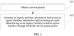
- An embodiment of this application provides a method for obtaining path information.
- the method is applied to a forwarding device, and the forwarding device may be a switch or a router. As shown in FIG. 1 , the method includes the following steps.
- the service packet is a target service packet or an updated target service packet
- the target service packet is a service packet that matches a flow rule
- the flow rule is used to obtain the service packet that matches the flow rule.
- the ingress interface information field is generated according to the path detection tag on the ingress interface through which the service packet passes, and the ingress interface information field is included in the service packet and is forwarded.
- S102 may be replaced by S103 in which an egress interface information field is generated according to a path detection tag on an egress interface through which the service packet passes. Therefore, after the service packet is obtained, the egress interface information field is generated according to the path detection tag on the egress interface through which the service packet passes, and the egress interface information field is included in the service packet and is forwarded.
- S102 may be replaced by S104 in which the ingress interface information field and the egress interface information field are generated according to a first path detection tag on the ingress interface and a second path detection tag on the egress interface through which the service packet passes. Therefore, after the service packet is obtained, the ingress interface information field and the egress interface information field are generated according to the first path detection tag on the ingress interface and the second path detection tag on the egress interface through which the service packet passes, and the ingress interface information field and the egress interface information field are included in the service packet and are forwarded.
- the ingress interface information field and/or the egress interface information field are/is generated according to the path detection tag configured on the ingress interface and/or the egress interface of the forwarding device, and the generated ingress interface information field and/or egress interface information field are/is carried in the received service packet and are/is forwarded to a destination node.
- Ingress interface information or/and egress interface information of the forwarding device is/are directly configured in the service packet according to an instruction of the path detection tag, to obtain a forwarding path of the service packet, so that the forwarding path of the service packet can be accurately obtained, and fewer network resources are consumed.
- the forwarding device is an ingress device
- the path detection tag and the flow rule are preconfigured on an ingress interface of the ingress device, where the path detection tag is used to instruct the forwarding device to configure the ingress interface information of the forwarding device.
- the ingress device is a device for initiating to forward the service packet.
- the ingress device determines whether a packet characteristic field included in the service packet matches a flow rule on the ingress interface of the forwarding device, and if the packet characteristic field included in the service packet matches the flow rule, determines that the service packet is a target service packet. There may be one or more flow rules on the ingress interface.
- the path detection tag and the flow rule are preconfigured on an egress interface of the ingress device, where the path detection tag is used to instruct the forwarding device to configure the egress interface information of the forwarding device.
- the ingress device is a device for initiating to forward the service packet.
- the ingress device determines whether a packet characteristic field included in the service packet matches a flow rule on the egress interface of the forwarding device, and if the packet characteristic field included in the service packet matches the flow rule, determines that the service packet is a target service packet. There may be one or more flow rules on the egress interface.
- the forwarding device is an ingress device
- the first path detection tag and a first flow rule are preconfigured on an ingress interface of the ingress device, where the first path detection tag is used to instruct the forwarding device to configure the ingress interface information of the forwarding device
- the second path detection tag and a second flow rule are preconfigured on an egress interface of the ingress device, where the second path detection tag is used to instruct the forwarding device to configure the egress interface information of the forwarding device.
- the ingress device is a device for initiating to forward the service packet.
- the ingress device determines whether a packet characteristic field included in the service packet matches a first flow rule on the ingress interface of the forwarding device, and if the packet characteristic field included in the service packet matches the first flow rule, determines that the service packet is a target service packet. There may be one or more flow rules on the ingress interface.
- the flow rule is information that is defined by operation and maintenance management personnel and that is used to describe or match the packet characteristic field of the service packet.
- the flow rule is used to screen the service packet by a forwarding device on which a flow rule is configured.
- the flow rule may be a characteristic of a service packet transmitted at a data link layer, and the characteristic of the service packet transmitted at the data link layer includes at least one of the following: a source MAC address, a destination MAC address, an Ether type, an inner virtual local area network identification (Virtual Local Area Network identification, VLAN ID), or an external VLAN ID.
- the service packet transmitted at the data link layer is mainly applied to a scenario of a data link layer virtual private network (Virtual Private Network, VPN) or an Ethernet virtual private network (EVPN).
- VPN Virtual Private Network
- EVPN Ethernet virtual private network
- the flow rule may be a characteristic of a service packet transmitted at a network layer, and the characteristic of the service packet transmitted at the network layer includes a source IP address, a destination IP address, a protocol type, a source port number, and a destination port number.
- An application scenario is mainly an IP network.
- the ingress device generates first ingress interface information according to a path detection tag on an ingress interface through which the target service packet passes and that is of the ingress device, and includes the first ingress interface information in connectivity fault management information of the target service packet.
- the connectivity fault management information may further include an Ether type field, a connectivity fault management header field, and an end field, and the connectivity fault management information is located at a tail of an Ethernet packet of the service packet.
- the ingress device forwards the target service packet.
- the ingress device generates first egress interface information according to a path detection tag on an egress interface through which the target service packet passes and that is of the ingress device, and includes the first egress interface information in connectivity fault management information of the target service packet.
- the connectivity fault management information further includes an Ether type field, a connectivity fault management header field, and an end field, and the connectivity fault management information is located at a tail of an Ethernet packet of the service packet. The ingress device forwards the target service packet.
- the ingress device generates first ingress interface information according to a path detection tag on an ingress interface through which the target service packet passes and that is of the ingress device.
- the ingress device generates a first egress interface information field according to a path detection tag on an egress interface through which the target service packet passes and that is of the ingress device.
- the ingress device includes the first ingress interface information and the first egress interface information in connectivity fault management information of the target service packet.
- the connectivity fault management information further includes an Ether type field, a connectivity fault management header field, and an end field, and the connectivity fault management information is located at a tail of an Ethernet packet of the service packet. The ingress device forwards the target service packet.
- a dummy packet of the target service packet may be generated according to a detection policy.
- the dummy packet is a new packet generated by duplicating a portion of the target service packet, and the new packet is used to obtain a forwarding path of the target service packet.
- the dummy packet may include a header that has a preset quantity of bytes and that is of the target service packet and the connectivity fault management information.
- a method for generating the dummy packet may include: duplicating and truncating the target service packet, calculating a remaining length of load of a truncated target service packet, and modifying a length field of an IP header of the truncated target service packet.
- the dummy packet may be terminated in a network, or may be discarded as an abnormal packet by a terminal host. Therefore, the dummy packet may be processed on a forwarding plane of the forwarding device, or the dummy packet may be processed and forwarded on a control plane. In this way, a length added to the service packet because path information is carried may be reduced.
- a remaining length of load of the IP packet may be calculated, and a Length field of the IP header is modified according to the remaining length of load of the IP packet.
- the path information is attached to a tail of a truncated packet, and a specific OAM flag is set on the IP header or an outer tunnel header of a packet, to indicate that the packet is an abnormal packet used for OAM detection.
- the dummy packet may be terminated on the network or discarded as an abnormal packet by the terminal host. Therefore, the dummy packet may be processed on a forwarding plane of the forwarding device, or may be processed and forwarded on a control plane. A relatively long forwarding delay caused by processing and forwarding on the control plane has no obvious impact on SLA of service traffic.
- the dummy packet of the target service packet may be generated by using either of the following manners: (1) Directly generate the dummy packet of the target service packet according to a detection policy. (2) Determine whether a length of the target service packet is greater than a preset threshold, and if the length of the target service packet is greater than the preset threshold, generate the dummy packet of the target service packet according to the target service packet.
- the first ingress interface information field or/and the first egress interface information field and the connectivity fault management information are generated according to a path detection tag on an ingress interface or/and an egress interface through which the dummy packet of the target service packet passes. If the length of the target service packet is less than the preset threshold, the first ingress interface information or/and the first egress interface information is/are generated according to the path detection tag on the ingress interface or/and the egress interface through which the target service packet passes.
- the ingress device includes the first ingress interface information and the first egress interface information in the connectivity fault management information of the target service packet.
- the connectivity fault management information further includes an Ether type field, a connectivity fault management header field, and an end field, and the connectivity fault management information is located at a tail of an Ethernet packet of the service packet.
- the ingress device forwards the target service packet.
- the dummy packet includes a header that has a preset quantity of bytes and that is of the target service packet, and a packet mark used to identify the dummy packet is set at a preset location of the dummy packet.
- a service packet obtained by the intermediate device is an updated target service packet, where the updated target service packet is a target service packet forwarded by the forwarding device, and the updated target service packet includes the connectivity fault management information.
- a path detection tag is preconfigured on an ingress interface or/and an egress interface of the intermediate device.
- a second ingress interface information field or/and a second egress interface information field is/are generated according to a path detection tag on an ingress interface or/and an egress interface through which the updated target service packet passes, to obtain another updated target service packet, where the another updated target service packet includes connectivity fault management information, the connectivity fault management information includes an Ether type field, a connectivity fault management header field, a first ingress interface information field or/and a first egress interface information field, the second ingress interface information field or/and the second egress interface information field, and an end field, and the connectivity fault management information is located at a tail of an Ethernet packet of the service packet; and the another updated target service packet is forwarded.
- the connectivity fault management information includes an Ether type field, a connectivity fault management header field, a first ingress interface information field or/and a first egress interface information field, the second ingress interface information field or/and the second egress interface information field, and an end field, and the connectivity fault management information is located at a tail of an Ethernet packet of
- a path detection untag is preconfigured on the egress device, where the path detection untag is used to instruct the egress device to parse and extract the connectivity fault management information and a packet characteristic field that are of the updated target service packet.
- the egress device may further configure the path detection tag.
- the service packet is parsed and extracted according to the path detection untag on the ingress interface or/and the egress interface through which the service packet passes, to obtain the connectivity fault management information and the packet characteristic field, where the connectivity fault management information includes an Ether type field, a connectivity fault management header field, one or more ingress interface information fields or/and one or more egress interface information fields, and an end field, the one or more ingress interface information fields or/and the one or more egress interface information fields form path information, the path information is used to indicate a forwarding path of the service packet in a forwarding path detection enabling network, and the service packet includes the connectivity fault management information and the packet characteristic field.
- the connectivity fault management information includes an Ether type field, a connectivity fault management header field, one or more ingress interface information fields or/and one or more egress interface information fields, and an end field, the one or more ingress interface information fields or/and the one or more egress interface information fields form path information, the path information is used to indicate a forwarding path of the service packet
- the service packet is a dummy packet
- the service packet is discarded.
- the connectivity fault management information is stripped, and the service packet continues to be forwarded.
- a forwarding path information table of the flow rule is generated and saved according to the packet characteristic field and the path information, so that the forwarding path information table is queried by a network management device or is sent to a network controller.
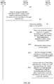
- An embodiment of this application provides a method for obtaining path information. As shown in FIG. 2A and FIG. 2B , the method includes the following steps.
- An ingress device obtains a service packet.
- the ingress device determines that a packet characteristic field of the service packet matches a flow rule, the service packet is a target service packet.
- the service packet includes the packet characteristic field.
- the flow rule may be configured into the ingress device by using a command-line interface (command-line interface, CLI) or a network management system (Network Management System, NMS), or by using a dynamic protocol such as the Border Gateway Protocol (Border Gateway Protocol, BGP) Passespec.
- the flow rule may be bound to an ingress interface or an egress interface of the ingress device according to a requirement of a flow direction (Ingress, Egress, or Both), so that a path detection tag is configured for the target service packet.
- the configured flow rule is applied to a specific interface, and it may be specified that the flow rule is effective for ingress traffic and/or egress traffic passing through the interface.
- the ingress device determines whether a length of the target service packet is greater than a preset threshold.
- the ingress device generates a dummy packet of the target service packet according to the target service packet.
- S205 is performed.
- the dummy packet is a new packet generated by duplicating a portion of the target service packet, and the new packet is used to obtain a forwarding path of the target service packet.
- the dummy packet may include a header that has a preset quantity of bytes and that is of the target service packet and connectivity fault management information.
- a packet mark used to identify the dummy packet is set at a preset location of the dummy packet.
- the preset quantity of bytes may be 96 bytes.
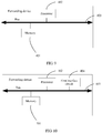
- a virtual extensible local area network header (Virtual Extensible LAN, VXLAN) packet header may include a flag bit of associated path detection. As shown in FIG.
- a mark of the dummy packet may be carried in an external Ether header (External Ether Header), an external IP header (External IP Header), and a VXLAN header (VXLAN Header (OAM flag)) after a User Datagram Protocol (User Datagram Protocol, UDP) header (Header).
- Ether Header External Ether Header
- IP Header External IP Header
- VXLAN Header VXLAN Header (OAM flag)
- UDP User Datagram Protocol
- UDP User Datagram Protocol
- the connectivity fault management information carried in the target service packet can be effectively recorded, and this can avoid a deficiency that the forwarding path of the service packet cannot be accurately obtained because the connectivity fault management information cannot be carried when the length of the target service packet is greater than the preset threshold.
- a method for generating the dummy packet may include: duplicating and truncating the target service packet, calculating a remaining length of load of a truncated target service packet, and modifying a length field of an IP header of the truncated target service packet.
- the dummy packet may be terminated in a network, or may be discarded as an abnormal packet by a terminal host. Therefore, the dummy packet may be processed on a forwarding plane of the forwarding device, or the dummy packet may be processed and forwarded on a control plane.
- a path maximum transmission unit (Maximum Transmission Unit, PMTU) TLV may be carried in the unicast forwarding packet.
- the forwarding device may know a PMTU of a network through which a current service forwarding packet passes. For example, a PMTU between an Ingress network virtualization edge (Network Virtualization Edge, NVE) and an Egress NVE in a network virtualization (Network Virtualization over Layer 3, NVO3) network over layer 3 (that is, a network layer) may be detected in advance, or a PMTU is carried in received connectivity fault management information.
- NVE Ingress network virtualization Edge
- NVO3 Network Virtualization over Layer 3, NVO3
- the forwarding device checks according to min ⁇ PMTU, an MTU of an egress interface ⁇ , or the forwarding device directly checks according to an MTU of an egress interface whether there is remaining space in the current forwarding packet to attach new path information. If space is insufficient, the new path information is not attached, and only a specific mark is set on a CFM header of the connectivity fault management information attached before the packet, to indicate to stop attaching path information.
- the ingress device generates ingress interface information or/and egress interface information of the ingress device according to a path detection tag.
- the ingress device may be any forwarding device on which a flow rule is configured.
- the path detection tag (Tag) is preconfigured on the ingress device. The path detection tag is used to instruct the forwarding device to configure the ingress interface information or the egress interface information of the forwarding device.
- the ingress device generates a first ingress interface information field or/and a first egress interface information field of the ingress device according to a path detection tag on an ingress interface or/and an egress interface through which the target service packet passes.
- the target service packet includes the connectivity fault management information, and the connectivity fault management information includes an Ether type (Ether Type) field, a connectivity fault management header (CFM header) field, the first ingress interface information (Forwarding Port TLV1) field or/and the first egress interface information (Forwarding Port TLV2) field, and an end field (End TLV) field.
- Ether type field may be 0x8902
- the connectivity fault management information is located at a tail of an Ethernet packet of the service packet, for example, may be a tail of a protocol data unit (Protocol Data Unit, PDU).
- the connectivity fault management information may further include a flow identifier TLV (Flow-id TLV), and the flow identifier TLV is located after a connectivity fault management header field (CFM header) and before Forwarding Port TLV.
- Flow-id TLV flow identifier TLV
- CFM header connectivity fault management header field
- the target service packet may be selected by means of time sampling or per-ratio sampling to configure path information, such as 100 ms or Is, or 1:100 or 1:10000.
- the ingress device forwards the target service packet to an intermediate device.
- the ingress device may forward the target service packet to the intermediate device according to forward information base (Forward Information Base, FIB) information of the ingress device.
- forward information base Forward Information Base
- a switch forwards a packet mainly according to a MAC address forwarding table
- a router forwards a packet mainly according to a routing table.
- the target service packet includes a packet characteristic and the connectivity fault management information.
- the intermediate device generates ingress interface information or/and egress interface information of a forwarding device according to a path detection tag.
- the intermediate device After the intermediate device receives the target service packet, if a path detection tag is configured on an ingress interface or/and an egress interface of the intermediate device, the intermediate device generates second ingress interface information or/and second egress interface information, and adds the second ingress interface information or/and the second egress interface information to the connectivity fault management information of the target service packet to obtain an updated target service packet. Specifically, the intermediate device may add the second ingress interface information or/and the second egress interface information to Forwarding Port TLV3 of the target service packet to obtain the updated target service packet.
- the intermediate device may further check a packet header of the received target service packet, if the packet header is greater than a preset length, continue to detect whether two bytes of the loaded packet header are 0x8902, and if the two bytes of the loaded packet header are 0x8902, continue to parse packet content having a remaining length according to a connectivity fault management protocol format. If there is no error during parsing, the target service packet includes the connectivity fault management information that carries the path information, and the path information is further added before the end field (END TLV).
- END TLV end field
- the ingress interface information may be an identifier of the ingress interface or an IP address of the ingress interface.
- the egress interface information may be an identifier of the egress interface or an IP address of the egress interface.
- the intermediate device forwards an updated target service packet to an egress device.
- the egress device may be any forwarding device on which a path detection untag (untag) is configured.
- the path detection untag is used to instruct the forwarding device to parse and extract connectivity fault management information and a packet characteristic that are of the updated target service packet.
- the egress device may further preconfigure the path detection tag.
- the updated target service packet includes the packet characteristic and the ingress interface information or/and the egress interface information of the forwarding device.
- the intermediate device may forward the target service packet to the egress device according to forward information base (Forward Information Base, FIB) information of the intermediate device.
- forward information base Forward Information Base
- a switch forwards a packet mainly according to a MAC forwarding table
- a router forwards a packet mainly according to a routing table.
- some intermediate devices may be forwarding nodes for transparently transmitting the target service packet. If no path detection tag or path detection untag is configured on an ingress interface (Ingress) or an egress interface (Egress) of the intermediate device, the target service packet is normally processed, there is no need to add the path information, and the connectivity fault management information that is carried in the target service packet is also not stripped.
- Ingress ingress interface
- Egress egress interface
- the egress device parses and extracts the updated target service packet according to a path detection untag to obtain the connectivity fault management information and the packet characteristic field.
- the connectivity fault management information includes an Ether type, a connectivity fault management header, the first ingress interface information or/and the first egress interface information, the second ingress interface information or/and the second egress interface information, and an end field, and the updated target service packet includes the packet characteristic.
- the one or more pieces of ingress interface information or/and one or more pieces of egress interface information form path information, and the path information is used to indicate a forwarding path of the service packet in a forwarding path detection enabling network.
- the egress device may be a sink node of the updated target service packet, or a forwarding device on which a path detection untag (untag) is configured.
- the sink node means that a service packet is a local service packet or a multicast service packet that needs to be terminated locally.
- a destination IP address of the updated target service packet is a local IP address of the egress device, and this service packet has no next hop information in a hit forwarding information table searched from the egress device.
- the egress device After the egress device receives the updated target service packet, if the path detection untag is configured on the ingress interface of the egress device, the egress device parses the updated target service packet to obtain the connectivity fault management information and the packet characteristic.
- the egress device saves the extracted packet characteristic and path information corresponding to the packet characteristic into a management information base (Management Information Base, MIB), so as to be queried by a measurement control point or be actively reported to a measurement control point.
- MIB Management Information Base
- the measurement control point may be a network management device or a network controller.
- ingress interface information or/and egress interface information of the egress device may be further generated according to a path detection tag on an ingress interface or/and an egress interface through which the updated target service packet passes and that is/are of the egress device.
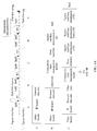
- R1 obtains a service packet, and a flow rule is preconfigured on R1. It is determined that a packet characteristic of the service packet matches the flow rule, and it is determined that the service packet is a target service packet. Then, the target service packet is forwarded by R2 and R3.
- R4 is an egress interface device for the target service packet.
- a path detection tag (Path-Info tag) is separately configured on an ingress interface of R1, an ingress interface and an egress interface of R2, an egress interface of R3, and an egress interface of R4, and a path detection untag (Path-Info untag) is further configured in R4.
- R1, R2, R3, and R4 are network devices, and may be routing devices or switching devices.
- the target service packet is forwarded by R1, R2, R3, and R4.
- a packet for the target service packet at a point A includes an Ether header (Ether Header), an IP header (IP Header), and a protocol data unit (PDU).
- Ether header Ether Header
- IP Header IP header
- PDU protocol data unit
- the point B is a location between R1 and R2 along a path that the target service packet passes from R1, R2, and R3 to R4.
- a flow identifier field is optional for carrying, and may be configured by operation and maintenance personnel when configuring the flow rule in an ingress device.
- the flow rule and the flow-id are in one-to-one mapping, to simplify an identifier of a packet. Even though there is no flow-id, the flow rule may continue to be used to identify the service packet.
- the ingress device adds CFM information to a tail of the specific packet or to a tail of a dummy packet duplicated from the specific packet.
- the CFM information includes an Ether type corresponding to CFM, a CFM header, a Flow-ID TLV, and an End TLV.
- the point C is a location between R2 and R3 along a path that the target service packet passes from R1, R2, and R3 to R4.
- the point D is a location between R3 and R4 along a path that the target service packet passes from R1, R2, and R3 to R4.
- a packet for the target service packet at a point E is parsed by R4 according to the path detection untag to obtain path information of the target service packet.
- the packet for the target service packet at the point E includes an Ether header (Ether Header), an IP header (IP Header), and a protocol data unit (PDU).
- R4 saves the path information into a management information base (MIB).
- MIB management information base
- content of the path information multiplexes a connectivity fault management (Connectivity Fault Management, CFM) header defined in 802.1AG, for example, an Ether type is 0x8902.
- CFM connectivity fault management
- Ether type is 0x8902.
- MD Level indicates a level
- Version indicates a version
- Flags indicate an identifier
- First TLV Offset indicates setting for a first type length value.
- a mark F is used to indicate whether the target service packet is a normal forwarding packet. Setting the mark F to 1 indicates a normal packet, and setting the mark F to 0 indicates a dummy packet, which duplicates a packet characteristic field of the normal forwarding packet.
- a mark P is used to indicate an end configuration mark. Because of a path maximum transmission unit (Maximum Transmission Unit, PMTU), space for carrying the path information by the target service packet is not enough, and an ingress interface or an egress interface stops to be configured.
- PMTU Maximum Transmission Unit
- Type Length Value TLV
- TLV Name Version (Standard/RFC/Draft) 0 End (end) IEEE 802.1AG 1 Sender ID (sender identifier) IEEE 802.1AG 2 Port Status (port status) IEEE 802.1AG 3 Data (data) IEEE 802.1AG 4 Interface Status (interface status) IEEE 802.1AG 5 Reply Ingress (reply ingress) IEEE 802.1AG 6 Reply Egress (reply egress) IEEE 802.1AG 7 LTM Egress Identifier (LTM egress identifier) IEEE 802.1AG 8 LTR Egress Identifier (LTR egress identifier) IEEE 802.1AG 9-30 Reserved (reserved) 31 Organization Specific (specific organization) IEEE 802.1AG TBD-TLV-64 OAM Application Identifier (OAM application identifier) draft-tissa-nvo3-oam-fm-01
- Node ID Type uses a definition of chassis ID subtype of Classis ID TLV of IEEE 802.1AB.
- a definition of Node ID uses a definition of chassis ID of Classis ID TLV of IEEE 802.1AB, and a specific value type is a type defined by Node ID Type.
- the Node ID is used to indicate an identifier of the forwarding device.
- Forwarding Port Desc Length is a string length of Forwarding Port Desc.
- Forwarding Port Description is description of a forwarding interface, and the interface may be a physical interface on the forwarding device, or may be a virtual interface.
- Physical Port Desc Length and Physical Port Description are optional fields, and exist only when the forwarding interface is a virtual interface.
- a mark I is used to indicate whether an interface is an ingress interface. Setting the mark I to 1 indicates an ingress interface, and setting the mark I to another value except 1 indicates an egress interface.
- a mark V is used to indicate that an ingress interface or an egress interface is a virtual interface, such as a Smartgroup interface, an MPPP interface, or a SuperVLAN interface.
- a virtual interface such as a Smartgroup interface, an MPPP interface, or a SuperVLAN interface.
- the two fields "Physical Port Desc Length” and "Physical Port Description" are valid.
- PMTU TLV An example of a coding format of PMTU TLV is as follows: +-+-+-+-+-+-+-+-+-+-+-+-+-+-+-+-+-+-+-+-+-+-+-+-+-+-+-+-+-+-+-+-+-+-+-+-+-+-+-+-+-+-+-+-+-+-+-+-+-+-+
- a network management system configures a path detection tag on a corresponding interface of a network virtualization edge (Network Virtualization Edge, NVE) 1, an NVE 2, an NVE gateway (Gateway, GW), a Spine switch (Switch, SW) 1, a Spine SW 2, and a Spine SW 3, and configures a path detection untag on the NVE 2.
- NVE Network Virtualization Edge
- a flow rule is configured on an ingress interface of the NVE 1, to match a service packet generated when a VM 1 of a tenant A in a subnetwork B accesses a VM 2 of the tenant A in a subnetwork C, so as to detect a forwarding path of the service packet in a data center switching network.
- Per-period sampling is configured, and one packet is sampled within 100 milliseconds (ms).
- the NVE 1 matches, according to the flow rule within a sampling period, a service packet received from the ingress interface, and if the service packet matches the preconfigured flow rule, determines that the service packet is a target service packet.
- the NVE 1 configures path information for the target service packet.
- the path information includes an Ether type 0x8902, a CFM header, Forwarding Port TLV 1, and End TLV.
- the NVE 1 searches for a forwarding information table in the NVE 1 according to a virtual local area network (Virtual Local Area Network, VLAN) ID of the target service packet and a MAC address of the NVE 1, to obtain VXLAN tunnel encapsulation information.
- a destination of a VXLAN tunnel is an NVE GW.
- the NVE 1 adds VXLAN tunnel encapsulation to the target service packet, searches for a route according to an outer destination IP address of the VXLAN tunnel, and if there are multiple equal-cost paths, selects a path passing through a Spine SW 1 to forward an encapsulated target service packet to the NVE GW.
- a value of a Length field in a VXLAN tunnel outer IP header does not include a packet content length of the path information.
- the Spine SW 1 After receiving the target service packet, the Spine SW 1 configures Forwarding Port TLV 2 corresponding to the ingress interface before the End TLV field according to the path detection tag, continues to search for the MAC forwarding information table to obtain an egress interface of the packet, finds, by means of checking, that the path detection tag is configured on the egress interface, configures Forwarding Port TLV 3 corresponding to the egress interface before the End TLV field, and then sends the target service packet to the NVE GW.
- the NVE GW After receiving the target service packet, the NVE GW strips the VXLAN tunnel encapsulation, searches for a route according to a VXLAN network identifier (VXLAN Network Identifier, VNI) and an inner IP header that are of the VXLAN header, and determines that a next hop of the target service packet is the NVE 2.
- VNI VXLAN Network Identifier
- the NVE GW first modifies an inner Ether header of the target service packet according to corresponding Address Resolution Protocol (Address Resolution Protocol, ARP) information, changes the destination MAC address of the target service packet to a MAC address of the VM 2, then performs VXLAN tunnel encapsulation of the NVE 2 for the target service packet, searches for a route according to an outer destination IP address of the VXLAN tunnel, selects a path passing through the Spine SW 2 to forward an encapsulated packet to the NVE 2, before forwarding the encapsulated packet to the NVE 2, checks a path detection tag configured on an egress interface of the encapsulated packet, configures Forwarding Port TLV 4 corresponding to the egress interface before the End TLV field, and then sends the target service packet to the Spine SW 2.
- ARP Address Resolution Protocol
- the Spine SW 2 finds, by means of checking, that the path detection tag is configured on the ingress interface, configures Forwarding Port TLV 5 corresponding to the ingress interface before the End TLV field, continues to search for the MAC forwarding information table to obtain an egress interface of the packet, finds, by means of checking, that the path detection tag is configured on the egress interface, configures Forwarding Port TLV 6 corresponding to the egress interface before the End TLV field, and then sends the target service packet to the NVE 2.
- the NVE 2 After receiving the target service packet, the NVE 2 strips the VXLAN tunnel encapsulation, searches for the MAC forwarding information table according to VNI and an inner MAC header of the VXLAN header to obtain an egress interface (that is, the ingress interface of the NVE 2) of the target service packet, finds, by means of checking, that the path detection untag is configured on the egress interface, strips routing information from a tail of the target service packet, extracts characteristic information of the target service packet, saves the characteristic information and the path information into an MIB of the path information to be queried and used by an NMS, and forwards the packet to the VM 2.
- an egress interface that is, the ingress interface of the NVE 2
- An embodiment of this application provides a forwarding device 30, as shown in FIG. 5 , including:
- the ingress interface information field or/and the egress interface information field is/are generated according to the path detection tag on the ingress interface or/and the egress interface through which the service packet passes.
- the path detection tag is configured in the forwarding device
- the ingress interface information or/and the egress interface information of the forwarding device is/are directly configured in the service packet according to the instruction of the path detection tag, to obtain the forwarding path of the service packet, so that the forwarding path of the service packet can be accurately obtained, and fewer network resources are consumed.
- the service packet is a target service packet.
- the forwarding device 30 further includes a determining unit 303 and a first sending unit 304.
- the determining unit 303 is configured to determine that a packet characteristic field of the service packet matches the flow rule, and determine that the service packet is the target service packet, where the service packet includes the packet characteristic field.
- the flow rule is information that is defined by operation and maintenance management personnel and that is used to describe or match the packet characteristic field of the service packet.
- the flow rule is used to screen the service packet by a forwarding device on which a flow rule is configured.
- a flow rule may be a characteristic of a service packet transmitted at a data link layer (L2), where the characteristic of the service packet transmitted at L2 includes a source MAC, a destination MAC, an Ether type, an inner virtual local area network identification (Virtual Local Area Network identification, VLAN ID), and an external VLAN ID, and is mainly applied to a scenario of an L2 virtual private network (Virtual Private Network, VPN) or an Ethernet virtual private network (EVPN).
- L2 virtual private network Virtual Private Network, VPN
- EVPN Ethernet virtual private network
- the flow rule may be a characteristic of a service packet transmitted at a network layer (L3), and the characteristic of the service packet transmitted at L3 includes a source IP, a destination IP, a protocol type, a source port, and a destination port.
- An application scenario is mainly an IP network.
- the generation unit 302 is specifically configured to: generate a first ingress interface information field or/and a first egress interface information field and connectivity fault management information according to the path detection tag on the ingress interface or/and the egress interface through which the target service packet passes, where the target service packet includes the connectivity fault management information, the connectivity fault management information includes an Ether type field, a connectivity fault management header field, the first ingress interface information field or/and the first egress interface information field, and an end field, and the connectivity fault management information is located at a tail of an Ethernet packet of the service packet.
- the first sending unit 304 is configured to forward the target service packet.
- the generation unit 302 is further configured to: generate a dummy packet of the target service packet according to a detection policy, where the dummy packet includes the connectivity fault management information.
- the generation unit 302 is specifically configured to:
- the connectivity fault management information carried in the target service packet can be effectively recorded, and this can avoid a deficiency that the forwarding path of the service packet cannot be accurately obtained because the connectivity fault management information cannot be carried when the length of the target service packet is greater than the preset threshold.
- the service packet is the updated target service packet.
- the generation unit 302 is specifically configured to: generate a second ingress interface information field or/and a second egress interface information field according to a path detection tag on an ingress interface or/and an egress interface through which the updated target service packet passes, to obtain another updated target service packet, where the another updated target service packet includes connectivity fault management information, the connectivity fault management information includes an Ether type field, a connectivity fault management header field, a first ingress interface information field or/and a first egress interface information field, the second ingress interface information field or/and the second egress interface information field, and an end field, and the connectivity fault management information is located at a tail of an Ethernet packet of the service packet.
- the forwarding device 30 further includes: a second sending unit 305, configured to forward the another updated target service packet.
- the forwarding device 30 When the forwarding device is an egress device, as shown in FIG. 8 , the forwarding device 30 further includes:
- the forwarding device 30 further includes: a configuration unit 309, configured to preconfigure at least one of the path detection tag, the path detection untag, or the flow rule, where the path detection tag is used to instruct the forwarding device to configure the ingress interface information or the egress interface information of the forwarding device, and the path detection untag is used to instruct the forwarding device to parse and extract connectivity fault management information and a packet characteristic field of an updated target service packet.
- a configuration unit 309 configured to preconfigure at least one of the path detection tag, the path detection untag, or the flow rule, where the path detection tag is used to instruct the forwarding device to configure the ingress interface information or the egress interface information of the forwarding device, and the path detection untag is used to instruct the forwarding device to parse and extract connectivity fault management information and a packet characteristic field of an updated target service packet.
- the forwarding device 30 may be a router or a switch.
- the forwarding device 30 may perform the method embodiment corresponding to FIG. 1 or FIG. 2A and FIG. 2B .
- An embodiment of this application provides a forwarding device 40, as shown in FIG. 9 , including:
- the ingress interface information field or/and the egress interface information field is/are generated according to the path detection tag on the ingress interface or/and the egress interface through which the service packet passes.
- the path detection tag is configured in the forwarding device
- the ingress interface information or/and the egress interface information of the forwarding device is/are directly configured in the service packet according to the instruction of the path detection tag, to obtain the forwarding path of the service packet, so that the forwarding path of the service packet can be accurately obtained, and fewer network resources are consumed.
- the processor 402 is further configured to: determine that a packet characteristic field of the service packet matches the flow rule, and determine that the service packet is the target service packet, where the service packet includes the packet characteristic field.
- the processor 402 is specifically configured to: generate a first ingress interface information field or/and a first egress interface information field and connectivity fault management information according to the path detection tag on the ingress interface or/and the egress interface through which the target service packet passes, where the target service packet includes the connectivity fault management information, the connectivity fault management information includes an Ether type field, a connectivity fault management header field, the first ingress interface information field or/and the first egress interface information field, and an end field, and the connectivity fault management information is located at a tail of an Ethernet packet of the service packet.
- the forwarding device 40 further includes: a first interface circuit 404, configured to forward the target service packet.
- the processor 402 is further configured to: generate a dummy packet of the target service packet according to a detection policy, where the dummy packet includes the connectivity fault management information.
- the processor 402 is specifically configured to:
- the connectivity fault management information carried in the target service packet can be effectively recorded, and this can avoid a deficiency that the forwarding path of the service packet cannot be accurately obtained because the connectivity fault management information cannot be carried when the length of the target service packet is greater than the preset threshold.
- the service packet is the updated target service packet.
- the processor 402 is specifically configured to: generate a second ingress interface information field or/and a second egress interface information field according to a path detection tag on an ingress interface or/and an egress interface through which the updated target service packet passes, to obtain another updated target service packet, where the another updated target service packet includes connectivity fault management information, the connectivity fault management information includes an Ether type field, a connectivity fault management header field, a first ingress interface information field or/and a first egress interface information field, the second ingress interface information field or/and the second egress interface information field, and an end field, and the connectivity fault management information is located at a tail of an Ethernet packet of the service packet.
- the forwarding device 40 further includes: a second interface circuit 405, configured to forward the another updated target service packet.
- the processor 402 is specifically configured to: parse and extract the service packet according to a path detection untag on the ingress interface or/and the egress interface through which the service packet passes, to obtain connectivity fault management information and a packet characteristic field, where the connectivity fault management information includes an Ether type field, a connectivity fault management header field, one or more ingress interface information fields or/and one or more egress interface information fields, and an end field, the one or more ingress interface information fields or/and the one or more egress interface information fields form path information, the path information is used to indicate a forwarding path of the service packet in a forwarding path detection enabling network, and the service packet includes the connectivity fault management information and the packet characteristic field.
- the connectivity fault management information includes an Ether type field, a connectivity fault management header field, one or more ingress interface information fields or/and one or more egress interface information fields, and an end field, the one or more ingress interface information fields or/and the one or more egress interface information fields form path information
- the path information is used
- the processor 402 is further configured to: when the service packet is a dummy packet, discard the service packet.
- the forwarding device 40 further includes: a third interface circuit 406, configured to: when the service packet is a normal packet, strip the connectivity fault management information, and continue to forward the service packet.
- the processor 402 is further configured to: generate and save a forwarding path information table of the flow rule according to the packet characteristic field and the path information, so that the forwarding path information table is queried by a network management device or is sent to a network controller.
- the processor 402 is further configured to: preconfigure at least one of the path detection tag, the path detection untag, or the flow rule, where the path detection tag is used to instruct the forwarding device to configure the ingress interface information or the egress interface information of the forwarding device, and the path detection untag is used to instruct the forwarding device to parse and extract connectivity fault management information and a packet characteristic field of an updated target service packet.
- the processor 402 herein may be one processor or may be a collective term of multiple processing elements.
- the processor may be a central processing unit (Central Processing Unit, CPU), or may be an application-specific integrated circuit (Application Specific Integrated Circuit, ASIC), or one or more integrated circuits that are configured to implement this embodiment of this application, such as one or more microprocessors (digital signal processor, DSP) or one or more field programmable gate arrays (Field Programmable Gate Array, FPGA).
- CPU Central Processing Unit
- ASIC Application Specific Integrated Circuit
- DSP digital signal processor
- FPGA Field Programmable Gate Array
- the memory 401 may be a storage apparatus, or may be a collective term of multiple storage elements, and is configured to store executable program code and the like.
- the memory 401 may include a random access memory (RAM), or may include a non-volatile memory (non-volatile memory), such as a magnetic disk storage, a flash (Flash), and the like.
- the bus 403 may be an industry standard architecture (Industry Standard Architecture, ISA) bus, a peripheral component interconnect (Peripheral Component, PCI) bus, an extended industry standard architecture (Extended Industry Standard Architecture, EISA) bus, or the like.
- the bus 404 may be categorized into an address bus, a data bus, a control bus, and the like. For ease of illustration, only one bold line is used in FIG. 9 to represent the bus, which, however, does not mean there is only one bus or only one type of bus.
- the interface circuit may be an interface circuit for implementing a wired connection.
- the forwarding device 30 may be a router or a switch.
- the forwarding device 40 may perform the method embodiment corresponding to FIG. 1 or FIG. 2A and FIG. 2B .
- the disclosed apparatus and method may be implemented in other manners.
- the described apparatus embodiment is merely an example.
- the unit division is merely logical function division and may be other division in actual implementation.
- a plurality of units or components may be combined or integrated into another system, or some features may be ignored or not performed.
- the displayed or discussed mutual couplings or direct couplings or communication connections may be implemented by using some interfaces.
- the indirect couplings or communication connections between the apparatuses or units may be implemented in electronic, mechanical, or other forms.
- the units described as separate parts may or may not be physically separate, and parts displayed as units may or may not be physical units, may be located in one position, or may be distributed on a plurality of network units. Some or all of the units may be selected according to actual requirements to achieve the objectives of the solutions of the embodiments.
- functional units in the embodiments of this application may be integrated into one processing unit, or each of the units may exist alone physically, or two or more units are integrated into one unit.
- the integrated unit may be implemented in a form of hardware, or may be implemented in a form of hardware in addition to a software functional unit.
- the program may be stored in a computer readable storage medium. When the program runs, the steps of the method embodiments are performed.
- the foregoing storage medium includes: any medium that can store program code, such as a read-only memory (Read-Only Memory, ROM), a random access memory (Random Access Memory, RAM), a magnetic disk, or an optical disc.
Landscapes
- Engineering & Computer Science (AREA)
- Computer Networks & Wireless Communication (AREA)
- Signal Processing (AREA)
- Data Exchanges In Wide-Area Networks (AREA)
Claims (14)
- Verfahren zum Erhalten von Pfadinformationen, wobei das Verfahren auf eine Weiterleitungsvorrichtung angewendet wird und Folgendes umfasst:Erhalten (202), wenn die Weiterleitungsvorrichtung eine Eingangsvorrichtung ist, eines Zieldienstpakets, wobei das Zieldienstpaket ein Dienstpaket ist, das mit einer Flussregel übereinstimmt, und die Flussregel auf der Weiterleitungsvorrichtung vorkonfiguriert ist; undErzeugen (205), durch die Eingangsvorrichtung, von Eingangsschnittstelleninformationen oder/und Ausgangsschnittstelleninformationen gemäß einer Pfaderkennungsmarkierung auf einer Eingangsschnittstelle oder/und einer Ausgangsschnittstelle, durch die das Zieldienstpaket läuft;Weiterleiten (206), durch die Eingangsvorrichtung, eines aktualisierten Zieldienstpakets, wobei das Aktualisierungszieldienstpaket das Zieldienstpaket mit den Eingangsschnittstelleninformationen oder/und den Ausgangsschnittstelleninformationen ist,Erzeugen (207), wenn die Weiterleitungsvorrichtung eine Zwischenvorrichtung ist, eines zweiten Eingangsschnittstelleninformationsfelds oder/und eines zweiten Ausgangsschnittstelleninformationsfelds gemäß einer Pfaderkennungsmarkierung auf einer Eingangsschnittstelle oder/und einer Ausgangsschnittstelle, durch die das aktualisierte Zieldienstpaket läuft;wobei das Verfahren ferner Folgendes umfasst:Erhalten (207), durch die Zwischenvorrichtung, eines anderen aktualisierten Zieldienstpakets mit dem zweiten Eingangsschnittstelleninformationsfeld oder/und dem zweiten Ausgangsschnittstelleninformationsfeld, wobei das andere aktualisierte Zieldienstpaket Verbindungsfehlerverwaltungsinformationen umfasst, wobei die Verbindungsfehlerverwaltungsinformationen ein Feld der Ether-Art, ein Kopffeld für Verbindungsfehlerverwaltung, ein erstes Eingangsschnittstelleninformationsfeld oder/und ein erstes Ausgangsschnittstelleninformationsfeld, das zweite Eingangsschnittstelleninformationsfeld oder/und das zweite Ausgangsschnittstelleninformationsfeld und ein Endfeld umfassen und wobei die Verbindungsfehlerverwaltungsinformationen sich an einem Ende eines Ethernet-Pakets des anderen aktualisierten Zieldienstpakets befinden; undWeiterleiten (208), durch die Zwischenvorrichtung, des anderen aktualisierten Zieldienstpakets.
- Verfahren nach Anspruch 1, wobei es sich bei der Flussregel um Kennzeichenübereinstimmungsinformationen eines spezifischen Dienstpakets handelt.
- Verfahren nach Anspruch 1 oder 2, wobei:
das Zieldienstpaket Verbindungsfehlerverwaltungsinformationen umfasst, und die Verbindungsfehlerverwaltungsinformationen ein Feld der Ether-Art, ein Kopffeld für Verbindungsfehlerverwaltung, ein erstes Eingangsschnittstelleninformationsfeld oder/und ein erstes Ausgangsschnittstelleninformationsfeld und ein Endfeld umfassen. - Verfahren nach Anspruch 3, wobei sich die Verbindungsfehlerverwaltungsinformationen des Zieldienstpakets an einem Ende eines Ethernet-Pakets des Zieldienstpakets befinden.
- Verfahren nach einem der Ansprüche 1 bis 4, das ferner Folgendes umfasst:
wobei nach dem Erhalten (101) des Zieldienstpakets, das Verfahren ferner Folgendes umfasst:
Erzeugen eines Dummy-Pakets des Zieldienstpakets gemäß einer Erkennungsrichtlinie, wobei das Dummy-Paket die Verbindungsfehlerverwaltungsinformationen des Zieldienstpakets umfasst, wobei die Erkennungsrichtlinie eine Bestimmung, ob eine Länge des Zieldienstpakets größer als ein voreingestellter Schwellenwert ist, einschließt. - Verfahren nach Anspruch 5, wobei das Erzeugen des Dummy-Pakets des Zieldienstpakets gemäß der Erkennungsrichtlinie Folgendes umfasst:direktes Erzeugen des Dummy-Pakets des Zieldienstpakets gemäß einer Anweisung der Erkennungsrichtlinie; oderBestimmen, ob die Länge des Zieldienstpakets größer als der voreingestellte Schwellenwert ist;falls die Länge des Zieldienstpakets größer als der voreingestellte Schwellenwert ist, Erzeugen des Dummy-Pakets des Zieldienstpakets gemäß dem Zieldienstpaket, und Erzeugen der ersten Eingangsschnittstelleninformationen oder/und der ersten Ausgangsschnittstelleninformationen und der Verbindungsfehlerverwaltungsinformationen des Zieldienstpakets gemäß der Pfaderkennungsmarkierung auf der Eingangsschnittstelle oder/und der Ausgangsschnittstelle, durch die das Dummy-Paket des Zieldienstpakets läuft; oderfalls die Länge des Zieldienstpakets kleiner als der voreingestellte Schwellenwert ist, Erzeugen eines ersten Eingangsschnittstelleninformationsfelds oder/und eines ersten Ausgangsschnittstelleninformationsfelds und der Verbindungsfehlerverwaltungsinformationen des Zieldienstpakets gemäß der Pfaderkennungsmarkierung auf der Eingangsschnittstelle oder/und der Ausgangsschnittstelle, durch die das Zieldienstpaket läuft, wobei das Dummy-Paket ferner einen Kopf, der eine voreingestellte Anzahl von Bytes aufweist und der von dem Zieldienstpaket stammt, und ein Paketzeichen umfasst, das verwendet wird, um zu identifizieren, dass das Dummy-Paket an einer voreingestellten Stelle des Dummy-Pakets gesetzt ist.
- Verfahren nach Anspruch 1, wobei, wenn die Weiterleitungsvorrichtung eine Ausgangsvorrichtung ist, und ferner nach dem Erhalten (101) des Zieldienstpakets ein Parsen und ein Extrahieren des Zieldienstpakets gemäß einer Pfaderkennungsentmarkierung auf der Eingangsschnittstelle oder/und der Ausgangsschnittstelle, durch die das Zieldienstpaket läuft, umfasst, um Verbindungsfehlerverwaltungsinformationen des Zieldienstpakets und ein Paketkennzeichenfeld des Zieldienstpakets zu erhalten, wobei die Verbindungsfehlerverwaltungsinformationen des Zieldienstpakets ein Feld der Ether-Art, ein Kopffeld für Verbindungsfehlerverwaltung, ein oder mehrere Eingangsschnittstelleninformationsfelder oder/und ein oder mehrere Ausgangsschnittstelleninformationsfelder und ein Endfeld umfassen, wobei das eine oder die mehreren Eingangsschnittstelleninformationsfelder oder/und das eine oder die mehreren Ausgangsschnittstelleninformationsfelder Pfadinformationen ausbilden, wobei die Pfadinformationen verwendet werden, um einen Weiterleitungspfad des Zieldienstpakets in einem Weiterleitungspfaderkennungsaktivierungsnetzwerk anzugeben.
- Verfahren nach Anspruch 7, wobei das Verfahren ferner Folgendes umfasst:nach dem Parsen und dem Extrahieren des Zieldienstpakets gemäß der Pfaderkennungsentmarkierung auf der Eingangsschnittstelle oder/und der Ausgangsschnittstelle, durch die das Zieldienstpaket läuft, wenn das Zieldienstpaket ein Dummy-Paket ist, Verwerfen des Zieldienstpakets;wenn das Zieldienstpaket ein normales Paket ist, Entfernen der Verbindungsfehlerverwaltungsinformationen des Zieldienstpakets und Fortfahren damit, das Zieldienstpaket weiterzuleiten; undErzeugen und Speichern einer Weiterleitungspfadinformationstabelle der Flussregel gemäß dem Paketkennzeichenfeld und den Pfadinformationen, sodass die Weiterleitungspfadinformationstabelle durch eine Netzwerkverwaltungsvorrichtung abgefragt oder an eine Netzwerksteuerung gesendet wird.
- Verfahren nach einem der Ansprüche 1 bis 8, wobei das Verfahren ferner Folgendes umfasst:
vordem Erhalten (101) eines Zieldienstpakets, Vorkonfigurieren der Pfaderkennungsmarkierung, der Pfaderkennungsentmarkierung und/oder der Flussregel, wobei die Pfaderkennungsentmarkierung verwendet wird, um die Weiterleitungsvorrichtung anzuweisen, Verbindungsfehlerverwaltungsinformationen und ein Paketkennzeichenfeld eines aktualisierten Zieldienstpakets zu parsen und extrahieren. - Weiterleitungsvorrichtung, wobei, wenn die Weiterleitungsvorrichtung eine Eingangsvorrichtung (30) ist, sie Folgendes umfasst:eine Erhaltungseinheit (301), die konfiguriert ist, um ein Zieldienstpaket zu erhalten, wobei das Zieldienstpaket ein Dienstpaket ist, das mit einer Flussregel übereinstimmt, und die Flussregel verwendet wird, um das Dienstpaket, das mit der Flussregel übereinstimmt, zu erhalten;eine Erzeugungseinheit (302), die konfiguriert ist, um ein Eingangsschnittstelleninformationsfeld oder/und ein Ausgangsschnittstelleninformationsfeld gemäß einer Pfaderkennungsmarkierung auf einer Eingangsschnittstelle oder/und einer Ausgangsschnittstelle, durch die das Zieldienstpaket läuft, zu erzeugen; undeine erste Sendeeinheit (304), die konfiguriert ist, um ein aktualisiertes Zieldienstpaket weiterzuleiten, wobei das Aktualisierungszieldienstpaket das Zieldienstpaket mit den Eingangsschnittstelleninformationen oder/und den Ausgangsschnittstelleninformationen ist, wobei, wenn die Weiterleitungsvorrichtung eine Zwischenvorrichtung ist, sie Folgendes umfasst:eine Erzeugungseinheit (302) ist speziell für Folgendes konfiguriert:Erzeugen eines zweiten Eingangsschnittstelleninformationsfelds oder/und eines zweiten Ausgangsschnittstelleninformationsfelds gemäß einer Pfaderkennungsmarkierung auf einer Eingangsschnittstelle oder/und einer Ausgangsschnittstelle, durch die das aktualisierte Zieldienstpaket läuft, um ein anderes aktualisiertes Zieldienstpaket zu erhalten, wobei das andere aktualisierte Zieldienstpaket Verbindungsfehlerverwaltungsinformationen umfasst, wobei die Verbindungsfehlerverwaltungsinformationen ein Feld der Ether-Art, ein Kopffeld für Verbindungsfehlerverwaltung, ein erstes Eingangsschnittstelleninformationsfeld oder/und ein erstes Ausgangsschnittstelleninformationsfeld, das zweite Eingangsschnittstelleninformationsfeld oder/und das zweite Ausgangsschnittstelleninformationsfeld und ein Endfeld umfassen und wobei die Verbindungsfehlerverwaltungsinformationen sich an einem Ende eines Ethernet-Pakets des Dienstpakets befinden; unddie Weiterleitungsvorrichtung ferner Folgendes umfasst:
eine zweite Sendeeinheit (305), die konfiguriert ist, um das andere aktualisierte Zieldienstpaket weiterzuleiten. - Weiterleitungsvorrichtung nach Anspruch 10, wobei, wenn die Weiterleitungsvorrichtung eine Eingangsvorrichtung ist, die Weiterleitungsvorrichtung ferner Folgendes umfasst:
eine Bestimmungseinheit (303), die konfiguriert ist, um zu bestimmen, dass ein Paketkennzeichenfeld des Zieldienstpakets mit der Flussregel übereinstimmt, wobei das Zieldienstpaket das Paketkennzeichenfeld umfasst. - Weiterleitungsvorrichtung nach Anspruch 11, wobei die Erzeugungseinheit (302) speziell für Folgendes konfiguriert ist:
Erzeugen eines ersten Eingangsschnittstelleninformationsfelds oder/und eines ersten Ausgangsschnittstelleninformationsfelds und von Verbindungsfehlerverwaltungsinformationen des Zieldienstpakets gemäß der Pfaderkennungsmarkierung auf der Eingangsschnittstelle oder/und der Ausgangsschnittstelle, durch die das Zieldienstpaket läuft, wobei die Verbindungsfehlerverwaltungsinformationen des Zieldienstpakets, die Verbindungsfehlerverwaltungsinformationen ein Feld der Ether-Art, ein Kopffeld für Verbindungsfehlerverwaltung, das erste Eingangsschnittstelleninformationsfeld oder/und das erste Ausgangsschnittstelleninformationsfeld und ein Endfeld umfassen und wobei die Verbindungsfehlerverwaltungsinformationen des Zieldienstpakets sich an einem Ende eines Ethernet-Pakets des Zieldienstpakets befinden. - Weiterleitungsvorrichtung nach einem der Ansprüche 10 bis 12, wobei die Erzeugungseinheit (302) ferner für Folgendes konfiguriert ist:
Erzeugen eines Dummy-Pakets des Zieldienstpakets gemäß einer Erkennungsrichtlinie, wobei das Dummy-Paket die Verbindungsfehlerverwaltungsinformationen des Zieldienstpakets umfasst. - Weiterleitungsvorrichtung nach Anspruch 13, wobei die Erzeugungseinheit (302) speziell für Folgendes konfiguriert ist:direktes Erzeugen des Dummy-Pakets des Zieldienstpakets gemäß einer Anweisung der Erkennungsrichtlinie; oderBestimmen, ob eine Länge des Zieldienstpakets größer als ein voreingestellter Schwellenwert ist;falls die Länge des Zieldienstpakets größer als der voreingestellte Schwellenwert ist, Erzeugen des Dummy-Pakets des Zieldienstpakets gemäß dem Zieldienstpaket, und Erzeugen des ersten Eingangsschnittstelleninformationsfelds oder/und des ersten Ausgangsschnittstelleninformationsfelds und der Verbindungsfehlerverwaltungsinformationen des Zieldienstpakets gemäß der Pfaderkennungsmarkierung auf der Eingangsschnittstelle oder/und der Ausgangsschnittstelle, durch die das Dummy-Paket des Zieldienstpakets läuft; oderfalls die Länge des Zieldienstpakets kleiner als der voreingestellte Schwellenwert ist, Erzeugen des ersten Eingangsschnittstelleninformationsfelds oder/und des ersten Ausgangsschnittstelleninformationsfelds und der Verbindungsfehlerverwaltungsinformationen des Zieldienstpakets gemäß der Pfaderkennungsmarkierung auf der Eingangsschnittstelle oder/und der Ausgangsschnittstelle, durch die das Zieldienstpaket läuft, wobei das Dummy-Paket ferner einen Kopf, der eine voreingestellte Anzahl von Bytes aufweist und der von dem Zieldienstpaket stammt, und ein Paketzeichen umfasst, das verwendet wird, um zu identifizieren, dass das Dummy-Paket an einer voreingestellten Stelle des Dummy-Pakets gesetzt ist.
Applications Claiming Priority (1)
| Application Number | Priority Date | Filing Date | Title |
|---|---|---|---|
| PCT/CN2015/095855 WO2017088190A1 (zh) | 2015-11-27 | 2015-11-27 | 一种获取路径信息的方法及装置 |
Publications (3)
| Publication Number | Publication Date |
|---|---|
| EP3306871A1 EP3306871A1 (de) | 2018-04-11 |
| EP3306871A4 EP3306871A4 (de) | 2018-08-22 |
| EP3306871B1 true EP3306871B1 (de) | 2021-08-11 |
Family
ID=58092106
Family Applications (1)
| Application Number | Title | Priority Date | Filing Date |
|---|---|---|---|
| EP15909101.6A Active EP3306871B1 (de) | 2015-11-27 | 2015-11-27 | Verfahren und vorrichtung zur erfassung von weginformationen |
Country Status (4)
| Country | Link |
|---|---|
| US (1) | US10554536B2 (de) |
| EP (1) | EP3306871B1 (de) |
| CN (1) | CN106464590B (de) |
| WO (1) | WO2017088190A1 (de) |
Families Citing this family (21)
| Publication number | Priority date | Publication date | Assignee | Title |
|---|---|---|---|---|
| US11070395B2 (en) * | 2015-12-09 | 2021-07-20 | Nokia Of America Corporation | Customer premises LAN expansion |
| US10594618B1 (en) * | 2017-06-06 | 2020-03-17 | Juniper Networks, Inc | Apparatus, system, and method for fragmenting packets into segments that comply with the maximum transmission unit of egress interfaces |
| CN107248941B (zh) * | 2017-06-30 | 2020-01-10 | 华为技术有限公司 | 一种检测路径的方法和装置 |
| CN107547347B (zh) * | 2017-07-25 | 2020-06-09 | 新华三技术有限公司 | 基于vni的路径调整方法和装置 |
| US10721338B2 (en) * | 2017-07-31 | 2020-07-21 | Nicira, Inc. | Application based egress interface selection |
| CN108111432B (zh) * | 2017-12-27 | 2021-07-02 | 新华三技术有限公司 | 报文转发方法及装置 |
| CN110324165B (zh) * | 2018-03-30 | 2021-05-11 | 华为技术有限公司 | 网络设备的管理方法、装置及系统 |
| CN108777646B (zh) * | 2018-05-02 | 2020-08-11 | 新华三技术有限公司 | 流量监控方法及装置 |
| CN108989206B (zh) * | 2018-08-22 | 2021-10-15 | 迈普通信技术股份有限公司 | 报文转发方法及装置 |
| TWI679861B (zh) * | 2018-09-06 | 2019-12-11 | 財團法人工業技術研究院 | 控制器、調整封包通信規則的方法及網路通信系統 |
| US11496399B2 (en) * | 2018-10-26 | 2022-11-08 | Cisco Technology, Inc. | Dynamically balancing traffic in a fabric using telemetry data |
| CN111327445B (zh) * | 2018-12-17 | 2023-09-12 | 中兴通讯股份有限公司 | 报文采样方法及解封装方法、节点、系统及存储介质 |
| CN112311580B (zh) * | 2019-08-01 | 2022-03-11 | 华为技术有限公司 | 报文传输路径确定方法、装置及系统、计算机存储介质 |
| CN110958180B (zh) * | 2019-11-14 | 2024-05-21 | 微民保险代理有限公司 | 网关路由方法、智能网关、电子设备及计算机存储介质 |
| CN112995034B (zh) * | 2019-12-02 | 2023-02-07 | 华为技术有限公司 | 业务路径确定方法和设备 |
| MX2023000301A (es) * | 2020-07-06 | 2023-02-09 | Huawei Tech Co Ltd | Metodo de procesamiento de paquetes y dispositivo de red. |
| CN113890858B (zh) * | 2021-09-29 | 2023-10-20 | 杭州迪普科技股份有限公司 | Pmtu的探测方法及装置 |
| CN114866398B (zh) * | 2022-03-24 | 2024-01-09 | 阿里巴巴(中国)有限公司 | 网络故障诊断方法及装置 |
| CN114760225B (zh) * | 2022-03-31 | 2024-10-11 | 深信服科技股份有限公司 | 一种故障诊断方法、系统和存储介质 |
| US11729148B1 (en) * | 2022-09-04 | 2023-08-15 | Uab 360 It | Optimized utilization of internet protocol addresses in a virtual private network |
| US12126528B2 (en) * | 2023-03-24 | 2024-10-22 | Nokia Solutions And Networks Oy | Egress rerouting of packets at a communication device |
Citations (1)
| Publication number | Priority date | Publication date | Assignee | Title |
|---|---|---|---|---|
| US20130242759A1 (en) * | 2012-03-16 | 2013-09-19 | Brocade Communications Systems, Inc. | Packet Tracing through Control and Data Plane Operations using SNMP Trap Commands |
Family Cites Families (10)
| Publication number | Priority date | Publication date | Assignee | Title |
|---|---|---|---|---|
| CN101227248B (zh) * | 2008-01-29 | 2011-05-25 | 中兴通讯股份有限公司 | 业务路径建立方法 |
| US7995483B1 (en) * | 2009-01-20 | 2011-08-09 | Juniper Networks, Inc. | Simultaneously testing connectivity to multiple remote maintenance endpoints of the same maintenance association |
| US8634308B2 (en) * | 2010-06-02 | 2014-01-21 | Brocade Communications Systems, Inc. | Path detection in trill networks |
| CN102271079B (zh) * | 2010-06-04 | 2014-11-05 | 华为技术有限公司 | 报文转发的方法、节点和系统 |
| CN102769552B (zh) * | 2012-07-31 | 2016-06-08 | 杭州华三通信技术有限公司 | 一种通过bfd检测lsp时传输bfd报文的方法和设备 |
| US9313093B2 (en) * | 2012-11-14 | 2016-04-12 | Ciena Corporation | Ethernet fault management systems and methods |
| US9270618B2 (en) * | 2013-02-28 | 2016-02-23 | International Business Machines Corporation | Source routing with fabric switches in an ethernet fabric network |
| US9559941B2 (en) * | 2013-07-01 | 2017-01-31 | Futurewei Technologies, Inc. | Locally protecting service in a label switched path network |
| US9917745B2 (en) * | 2013-09-27 | 2018-03-13 | Futurewei Technologies, Inc. | Validation of chained network services |
| CN105099915B (zh) * | 2014-04-28 | 2018-11-30 | 华为技术有限公司 | 一种建立业务路径的方法和设备 |
-
2015
- 2015-11-27 EP EP15909101.6A patent/EP3306871B1/de active Active
- 2015-11-27 CN CN201580022301.7A patent/CN106464590B/zh active Active
- 2015-11-27 WO PCT/CN2015/095855 patent/WO2017088190A1/zh not_active Ceased
-
2018
- 2018-01-09 US US15/866,305 patent/US10554536B2/en active Active
Patent Citations (1)
| Publication number | Priority date | Publication date | Assignee | Title |
|---|---|---|---|---|
| US20130242759A1 (en) * | 2012-03-16 | 2013-09-19 | Brocade Communications Systems, Inc. | Packet Tracing through Control and Data Plane Operations using SNMP Trap Commands |
Also Published As
| Publication number | Publication date |
|---|---|
| WO2017088190A1 (zh) | 2017-06-01 |
| EP3306871A4 (de) | 2018-08-22 |
| CN106464590A (zh) | 2017-02-22 |
| EP3306871A1 (de) | 2018-04-11 |
| US10554536B2 (en) | 2020-02-04 |
| CN106464590B (zh) | 2019-11-19 |
| US20180367438A9 (en) | 2018-12-20 |
| US20180159759A1 (en) | 2018-06-07 |
Similar Documents
| Publication | Publication Date | Title |
|---|---|---|
| US10554536B2 (en) | Method for obtaining path information and apparatus | |
| US11848757B2 (en) | In-situ passive performance measurement in a network environment | |
| US12160362B2 (en) | Traceroute for multi-path routing | |
| US12267230B2 (en) | Packet processing method and apparatus, network device, and storage medium | |
| US11876695B2 (en) | Path monitoring system (PMS) controller or ingress node based multiprotocal label switching (MPLS) ping and traceroute in inter-autonomous system (AS) segment routing (SR) networks | |
| US11979322B2 (en) | Method and apparatus for providing service for traffic flow | |
| US20230006906A1 (en) | In-situ flow detection method and apparatus | |
| CN111865774B (zh) | 多宿主网络节点和/或主机上的快速故障检测机制 | |
| US8634308B2 (en) | Path detection in trill networks | |
| US8885488B2 (en) | Reachability detection in trill networks | |
| US7808919B2 (en) | Network monitoring using a proxy | |
| US11057290B2 (en) | Ping/traceroute for static label switched paths (LSPs) and static segment routing traffic engineering (SRTE) tunnels | |
| CN105429841B (zh) | Nni ping的实现方法及装置 | |
| CN107888406A (zh) | 方法、系统和提供商边缘设备 | |
| JP6699065B2 (ja) | ネットワークパフォーマンスを測定するためのパケットサンプリング | |
| EP2509261B1 (de) | Überwachung eines Netzwerks in einem paketvermittelten Netzwerk | |
| CN101425942A (zh) | 一种实现双向转发检测的方法、装置及系统 | |
| WO2017000802A1 (zh) | 一种业务故障定位方法及装置 | |
| EP4287576A1 (de) | Fehlererkennungsverfahren, netzwerkvorrichtung und system | |
| Jain | Introduction to OpenFlow | |
| Bryant | An introduction to packet switching for sync engineers |
Legal Events
| Date | Code | Title | Description |
|---|---|---|---|
| STAA | Information on the status of an ep patent application or granted ep patent |
Free format text: STATUS: THE INTERNATIONAL PUBLICATION HAS BEEN MADE |
|
| PUAI | Public reference made under article 153(3) epc to a published international application that has entered the european phase |
Free format text: ORIGINAL CODE: 0009012 |
|
| STAA | Information on the status of an ep patent application or granted ep patent |
Free format text: STATUS: REQUEST FOR EXAMINATION WAS MADE |
|
| 17P | Request for examination filed |
Effective date: 20180104 |
|
| AK | Designated contracting states |
Kind code of ref document: A1 Designated state(s): AL AT BE BG CH CY CZ DE DK EE ES FI FR GB GR HR HU IE IS IT LI LT LU LV MC MK MT NL NO PL PT RO RS SE SI SK SM TR |
|
| AX | Request for extension of the european patent |
Extension state: BA ME |
|
| A4 | Supplementary search report drawn up and despatched |
Effective date: 20180724 |
|
| RIC1 | Information provided on ipc code assigned before grant |
Ipc: H04L 12/725 20130101ALI20180718BHEP Ipc: H04L 12/751 20130101ALI20180718BHEP Ipc: H04L 12/24 20060101ALI20180718BHEP Ipc: H04L 12/707 20130101ALI20180718BHEP Ipc: H04L 12/70 20130101AFI20180718BHEP Ipc: H04L 12/741 20130101ALI20180718BHEP Ipc: H04L 12/703 20130101ALI20180718BHEP Ipc: H04L 12/26 20060101ALI20180718BHEP |
|
| DAV | Request for validation of the european patent (deleted) | ||
| DAX | Request for extension of the european patent (deleted) | ||
| STAA | Information on the status of an ep patent application or granted ep patent |
Free format text: STATUS: EXAMINATION IS IN PROGRESS |
|
| 17Q | First examination report despatched |
Effective date: 20200309 |
|
| GRAP | Despatch of communication of intention to grant a patent |
Free format text: ORIGINAL CODE: EPIDOSNIGR1 |
|
| STAA | Information on the status of an ep patent application or granted ep patent |
Free format text: STATUS: GRANT OF PATENT IS INTENDED |
|
| INTG | Intention to grant announced |
Effective date: 20210310 |
|
| GRAS | Grant fee paid |
Free format text: ORIGINAL CODE: EPIDOSNIGR3 |
|
| GRAA | (expected) grant |
Free format text: ORIGINAL CODE: 0009210 |
|
| STAA | Information on the status of an ep patent application or granted ep patent |
Free format text: STATUS: THE PATENT HAS BEEN GRANTED |
|
| AK | Designated contracting states |
Kind code of ref document: B1 Designated state(s): AL AT BE BG CH CY CZ DE DK EE ES FI FR GB GR HR HU IE IS IT LI LT LU LV MC MK MT NL NO PL PT RO RS SE SI SK SM TR |
|
| REG | Reference to a national code |
Ref country code: CH Ref legal event code: EP |
|
| REG | Reference to a national code |
Ref country code: DE Ref legal event code: R096 Ref document number: 602015072310 Country of ref document: DE |
|
| REG | Reference to a national code |
Ref country code: IE Ref legal event code: FG4D Ref country code: AT Ref legal event code: REF Ref document number: 1420528 Country of ref document: AT Kind code of ref document: T Effective date: 20210915 |
|
| REG | Reference to a national code |
Ref country code: LT Ref legal event code: MG9D |
|
| REG | Reference to a national code |
Ref country code: NL Ref legal event code: MP Effective date: 20210811 |
|
| REG | Reference to a national code |
Ref country code: AT Ref legal event code: MK05 Ref document number: 1420528 Country of ref document: AT Kind code of ref document: T Effective date: 20210811 |
|
| PG25 | Lapsed in a contracting state [announced via postgrant information from national office to epo] |
Ref country code: LT Free format text: LAPSE BECAUSE OF FAILURE TO SUBMIT A TRANSLATION OF THE DESCRIPTION OR TO PAY THE FEE WITHIN THE PRESCRIBED TIME-LIMIT Effective date: 20210811 Ref country code: AT Free format text: LAPSE BECAUSE OF FAILURE TO SUBMIT A TRANSLATION OF THE DESCRIPTION OR TO PAY THE FEE WITHIN THE PRESCRIBED TIME-LIMIT Effective date: 20210811 Ref country code: BG Free format text: LAPSE BECAUSE OF FAILURE TO SUBMIT A TRANSLATION OF THE DESCRIPTION OR TO PAY THE FEE WITHIN THE PRESCRIBED TIME-LIMIT Effective date: 20211111 Ref country code: NO Free format text: LAPSE BECAUSE OF FAILURE TO SUBMIT A TRANSLATION OF THE DESCRIPTION OR TO PAY THE FEE WITHIN THE PRESCRIBED TIME-LIMIT Effective date: 20211111 Ref country code: PT Free format text: LAPSE BECAUSE OF FAILURE TO SUBMIT A TRANSLATION OF THE DESCRIPTION OR TO PAY THE FEE WITHIN THE PRESCRIBED TIME-LIMIT Effective date: 20211213 Ref country code: FI Free format text: LAPSE BECAUSE OF FAILURE TO SUBMIT A TRANSLATION OF THE DESCRIPTION OR TO PAY THE FEE WITHIN THE PRESCRIBED TIME-LIMIT Effective date: 20210811 Ref country code: ES Free format text: LAPSE BECAUSE OF FAILURE TO SUBMIT A TRANSLATION OF THE DESCRIPTION OR TO PAY THE FEE WITHIN THE PRESCRIBED TIME-LIMIT Effective date: 20210811 Ref country code: HR Free format text: LAPSE BECAUSE OF FAILURE TO SUBMIT A TRANSLATION OF THE DESCRIPTION OR TO PAY THE FEE WITHIN THE PRESCRIBED TIME-LIMIT Effective date: 20210811 Ref country code: SE Free format text: LAPSE BECAUSE OF FAILURE TO SUBMIT A TRANSLATION OF THE DESCRIPTION OR TO PAY THE FEE WITHIN THE PRESCRIBED TIME-LIMIT Effective date: 20210811 Ref country code: RS Free format text: LAPSE BECAUSE OF FAILURE TO SUBMIT A TRANSLATION OF THE DESCRIPTION OR TO PAY THE FEE WITHIN THE PRESCRIBED TIME-LIMIT Effective date: 20210811 |
|
| PG25 | Lapsed in a contracting state [announced via postgrant information from national office to epo] |
Ref country code: PL Free format text: LAPSE BECAUSE OF FAILURE TO SUBMIT A TRANSLATION OF THE DESCRIPTION OR TO PAY THE FEE WITHIN THE PRESCRIBED TIME-LIMIT Effective date: 20210811 Ref country code: LV Free format text: LAPSE BECAUSE OF FAILURE TO SUBMIT A TRANSLATION OF THE DESCRIPTION OR TO PAY THE FEE WITHIN THE PRESCRIBED TIME-LIMIT Effective date: 20210811 Ref country code: GR Free format text: LAPSE BECAUSE OF FAILURE TO SUBMIT A TRANSLATION OF THE DESCRIPTION OR TO PAY THE FEE WITHIN THE PRESCRIBED TIME-LIMIT Effective date: 20211112 |
|
| PG25 | Lapsed in a contracting state [announced via postgrant information from national office to epo] |
Ref country code: NL Free format text: LAPSE BECAUSE OF FAILURE TO SUBMIT A TRANSLATION OF THE DESCRIPTION OR TO PAY THE FEE WITHIN THE PRESCRIBED TIME-LIMIT Effective date: 20210811 |
|
| PG25 | Lapsed in a contracting state [announced via postgrant information from national office to epo] |
Ref country code: DK Free format text: LAPSE BECAUSE OF FAILURE TO SUBMIT A TRANSLATION OF THE DESCRIPTION OR TO PAY THE FEE WITHIN THE PRESCRIBED TIME-LIMIT Effective date: 20210811 |
|
| REG | Reference to a national code |
Ref country code: DE Ref legal event code: R097 Ref document number: 602015072310 Country of ref document: DE |
|
| PG25 | Lapsed in a contracting state [announced via postgrant information from national office to epo] |
Ref country code: SM Free format text: LAPSE BECAUSE OF FAILURE TO SUBMIT A TRANSLATION OF THE DESCRIPTION OR TO PAY THE FEE WITHIN THE PRESCRIBED TIME-LIMIT Effective date: 20210811 Ref country code: SK Free format text: LAPSE BECAUSE OF FAILURE TO SUBMIT A TRANSLATION OF THE DESCRIPTION OR TO PAY THE FEE WITHIN THE PRESCRIBED TIME-LIMIT Effective date: 20210811 Ref country code: RO Free format text: LAPSE BECAUSE OF FAILURE TO SUBMIT A TRANSLATION OF THE DESCRIPTION OR TO PAY THE FEE WITHIN THE PRESCRIBED TIME-LIMIT Effective date: 20210811 Ref country code: EE Free format text: LAPSE BECAUSE OF FAILURE TO SUBMIT A TRANSLATION OF THE DESCRIPTION OR TO PAY THE FEE WITHIN THE PRESCRIBED TIME-LIMIT Effective date: 20210811 Ref country code: CZ Free format text: LAPSE BECAUSE OF FAILURE TO SUBMIT A TRANSLATION OF THE DESCRIPTION OR TO PAY THE FEE WITHIN THE PRESCRIBED TIME-LIMIT Effective date: 20210811 Ref country code: AL Free format text: LAPSE BECAUSE OF FAILURE TO SUBMIT A TRANSLATION OF THE DESCRIPTION OR TO PAY THE FEE WITHIN THE PRESCRIBED TIME-LIMIT Effective date: 20210811 |
|
| PLBE | No opposition filed within time limit |
Free format text: ORIGINAL CODE: 0009261 |
|
| STAA | Information on the status of an ep patent application or granted ep patent |
Free format text: STATUS: NO OPPOSITION FILED WITHIN TIME LIMIT |
|
| PG25 | Lapsed in a contracting state [announced via postgrant information from national office to epo] |
Ref country code: MC Free format text: LAPSE BECAUSE OF FAILURE TO SUBMIT A TRANSLATION OF THE DESCRIPTION OR TO PAY THE FEE WITHIN THE PRESCRIBED TIME-LIMIT Effective date: 20210811 |
|
| REG | Reference to a national code |
Ref country code: CH Ref legal event code: PL |
|
| 26N | No opposition filed |
Effective date: 20220512 |
|
| GBPC | Gb: european patent ceased through non-payment of renewal fee |
Effective date: 20211127 |
|
| PG25 | Lapsed in a contracting state [announced via postgrant information from national office to epo] |
Ref country code: LU Free format text: LAPSE BECAUSE OF NON-PAYMENT OF DUE FEES Effective date: 20211127 Ref country code: IT Free format text: LAPSE BECAUSE OF FAILURE TO SUBMIT A TRANSLATION OF THE DESCRIPTION OR TO PAY THE FEE WITHIN THE PRESCRIBED TIME-LIMIT Effective date: 20210811 Ref country code: BE Free format text: LAPSE BECAUSE OF NON-PAYMENT OF DUE FEES Effective date: 20211130 |
|
| REG | Reference to a national code |
Ref country code: BE Ref legal event code: MM Effective date: 20211130 |
|
| PG25 | Lapsed in a contracting state [announced via postgrant information from national office to epo] |
Ref country code: SI Free format text: LAPSE BECAUSE OF FAILURE TO SUBMIT A TRANSLATION OF THE DESCRIPTION OR TO PAY THE FEE WITHIN THE PRESCRIBED TIME-LIMIT Effective date: 20210811 |
|
| PG25 | Lapsed in a contracting state [announced via postgrant information from national office to epo] |
Ref country code: IE Free format text: LAPSE BECAUSE OF NON-PAYMENT OF DUE FEES Effective date: 20211127 Ref country code: GB Free format text: LAPSE BECAUSE OF NON-PAYMENT OF DUE FEES Effective date: 20211127 |
|
| PG25 | Lapsed in a contracting state [announced via postgrant information from national office to epo] |
Ref country code: HU Free format text: LAPSE BECAUSE OF FAILURE TO SUBMIT A TRANSLATION OF THE DESCRIPTION OR TO PAY THE FEE WITHIN THE PRESCRIBED TIME-LIMIT; INVALID AB INITIO Effective date: 20151127 |
|
| PG25 | Lapsed in a contracting state [announced via postgrant information from national office to epo] |
Ref country code: CY Free format text: LAPSE BECAUSE OF FAILURE TO SUBMIT A TRANSLATION OF THE DESCRIPTION OR TO PAY THE FEE WITHIN THE PRESCRIBED TIME-LIMIT Effective date: 20210811 |
|
| PG25 | Lapsed in a contracting state [announced via postgrant information from national office to epo] |
Ref country code: LI Free format text: LAPSE BECAUSE OF NON-PAYMENT OF DUE FEES Effective date: 20220701 Ref country code: CH Free format text: LAPSE BECAUSE OF NON-PAYMENT OF DUE FEES Effective date: 20220701 |
|
| PG25 | Lapsed in a contracting state [announced via postgrant information from national office to epo] |
Ref country code: MK Free format text: LAPSE BECAUSE OF FAILURE TO SUBMIT A TRANSLATION OF THE DESCRIPTION OR TO PAY THE FEE WITHIN THE PRESCRIBED TIME-LIMIT Effective date: 20210811 |
|
| PG25 | Lapsed in a contracting state [announced via postgrant information from national office to epo] |
Ref country code: MT Free format text: LAPSE BECAUSE OF FAILURE TO SUBMIT A TRANSLATION OF THE DESCRIPTION OR TO PAY THE FEE WITHIN THE PRESCRIBED TIME-LIMIT Effective date: 20210811 |
|
| PGFP | Annual fee paid to national office [announced via postgrant information from national office to epo] |
Ref country code: FR Payment date: 20250930 Year of fee payment: 11 |
|
| PG25 | Lapsed in a contracting state [announced via postgrant information from national office to epo] |
Ref country code: TR Free format text: LAPSE BECAUSE OF FAILURE TO SUBMIT A TRANSLATION OF THE DESCRIPTION OR TO PAY THE FEE WITHIN THE PRESCRIBED TIME-LIMIT Effective date: 20210811 |
|
| PGFP | Annual fee paid to national office [announced via postgrant information from national office to epo] |
Ref country code: DE Payment date: 20250930 Year of fee payment: 11 |