EP3306838A1 - System and method for testing antenna arrays - Google Patents
System and method for testing antenna arrays Download PDFInfo
- Publication number
- EP3306838A1 EP3306838A1 EP16199018.9A EP16199018A EP3306838A1 EP 3306838 A1 EP3306838 A1 EP 3306838A1 EP 16199018 A EP16199018 A EP 16199018A EP 3306838 A1 EP3306838 A1 EP 3306838A1
- Authority
- EP
- European Patent Office
- Prior art keywords
- signal paths
- signal
- probe
- test
- measurement device
- Prior art date
- Legal status (The legal status is an assumption and is not a legal conclusion. Google has not performed a legal analysis and makes no representation as to the accuracy of the status listed.)
- Granted
Links
Images

Classifications
-
- H—ELECTRICITY
- H04—ELECTRIC COMMUNICATION TECHNIQUE
- H04B—TRANSMISSION
- H04B17/00—Monitoring; Testing
-
- H—ELECTRICITY
- H04—ELECTRIC COMMUNICATION TECHNIQUE
- H04B—TRANSMISSION
- H04B17/00—Monitoring; Testing
- H04B17/10—Monitoring; Testing of transmitters
- H04B17/11—Monitoring; Testing of transmitters for calibration
- H04B17/12—Monitoring; Testing of transmitters for calibration of transmit antennas, e.g. of the amplitude or phase
-
- G—PHYSICS
- G01—MEASURING; TESTING
- G01R—MEASURING ELECTRIC VARIABLES; MEASURING MAGNETIC VARIABLES
- G01R29/00—Arrangements for measuring or indicating electric quantities not covered by groups G01R19/00 - G01R27/00
- G01R29/08—Measuring electromagnetic field characteristics
- G01R29/10—Radiation diagrams of antennas
-
- H—ELECTRICITY
- H04—ELECTRIC COMMUNICATION TECHNIQUE
- H04B—TRANSMISSION
- H04B17/00—Monitoring; Testing
- H04B17/10—Monitoring; Testing of transmitters
- H04B17/101—Monitoring; Testing of transmitters for measurement of specific parameters of the transmitter or components thereof
- H04B17/102—Power radiated at antenna
-
- H—ELECTRICITY
- H04—ELECTRIC COMMUNICATION TECHNIQUE
- H04B—TRANSMISSION
- H04B17/00—Monitoring; Testing
- H04B17/10—Monitoring; Testing of transmitters
- H04B17/11—Monitoring; Testing of transmitters for calibration
-
- H—ELECTRICITY
- H04—ELECTRIC COMMUNICATION TECHNIQUE
- H04B—TRANSMISSION
- H04B17/00—Monitoring; Testing
- H04B17/30—Monitoring; Testing of propagation channels
- H04B17/309—Measuring or estimating channel quality parameters
- H04B17/364—Delay profiles
-
- H—ELECTRICITY
- H04—ELECTRIC COMMUNICATION TECHNIQUE
- H04B—TRANSMISSION
- H04B7/00—Radio transmission systems, i.e. using radiation field
- H04B7/02—Diversity systems; Multi-antenna system, i.e. transmission or reception using multiple antennas
- H04B7/04—Diversity systems; Multi-antenna system, i.e. transmission or reception using multiple antennas using two or more spaced independent antennas
- H04B7/0413—MIMO systems
-
- H—ELECTRICITY
- H04—ELECTRIC COMMUNICATION TECHNIQUE
- H04L—TRANSMISSION OF DIGITAL INFORMATION, e.g. TELEGRAPHIC COMMUNICATION
- H04L43/00—Arrangements for monitoring or testing data switching networks
- H04L43/12—Network monitoring probes
-
- H—ELECTRICITY
- H04—ELECTRIC COMMUNICATION TECHNIQUE
- H04B—TRANSMISSION
- H04B17/00—Monitoring; Testing
- H04B17/0082—Monitoring; Testing using service channels; using auxiliary channels
- H04B17/0085—Monitoring; Testing using service channels; using auxiliary channels using test signal generators
Definitions
- the invention relates to a system and a method for testing antenna arrays.
- the inventive system and method can be used for calibrating such antenna arrays.
- MIMO Multiple Input Multiple Output
- LTE Long Term Evolution
- US 2016/0269093 A1 discloses a communication method and apparatus using analog and digital beamforming with respect to MIMO. Nevertheless, the aforementioned document does not consider testing or calibrating an antenna array, which is essential for ensuring the proper functioning of the device under test, respectively the wireless communication.
- a system for testing and/or calibrating an antenna array comprises a device under test comprising the antenna array and at least one active radio frequency device for transmitting a test signal being known and always the same or at least partially the same on each of at least two signal paths, and a measurement device comprising at least one probe for receiving the test signal on each of the at least two signal paths.
- said test signal is advantageously a non-repeatable one at least for the time of testing and/or calibrating.
- At least one of amplitude, frequency, phase and spatial dependency changes over time.
- each of the at least two signal paths is unambiguously identifiable.
- the respective signal running from the at least one active radio frequency device to the corresponding antenna is delayed, wherein this delay may not be constant in comparison with the other signal paths.
- the test signal is a chirp signal.
- the at least one probe measures the output of each of the at least two signal paths at a defined time interval.
- the measurement device collects the measurement data with respect to each of the at least two signal paths.
- the measurement device measures the time needed for changing with the position of the at least one probe from one of the at least two signal paths to another one of the at least two signal paths.
- the measurement device calculates the phase of each of the at least two signal paths and/or the phase difference between each pair of the at least two signal paths and/or the amplitude of each of at least two signal paths and/or the amplitude difference between each pair of the at least two signal paths. In other words, this calculation is performed based on measured data with respect to the output of each of the at least two signal paths, time needed for changing with position of the at least one probe from one of the at least two signal paths to another one of the at least two signal paths, and time interval for measurement of each of the at least two signal paths.
- each signal of at least one pair of the at least two signal paths partially or completely comprises the same signal portions.
- the system further comprises a switch matrix for changing the position of the at least one probe from one of the at least two signal paths to another one of the at least two signal paths.
- a method for testing and/or calibrating an antenna array uses a device under test comprising the antenna array and at least one active radio frequency device and a measurement device comprising at least one probe. Furthermore, the method comprises the steps of transmitting a test signal being known and always the same or at least partially the same on each of at least two signal paths from the device under test, and receiving the test signal on each of the at least two signal paths with the aid of the at least one probe of the measurement device.
- the test signal is a non-repeatable one at least for the time of testing and/or calibrating.
- At least one of amplitude, frequency, phase and spatial dependency changes over time.
- each of the at least two signal paths is unambiguously identifiable.
- the respective signal running from the at least one active radio frequency device to the corresponding antenna is delayed, wherein this delay may not be constant in comparison with the other signal paths.
- the test signal is a chirp signal.
- the at least one probe measures the output of each of the at least two signal paths at a defined time interval.
- the measurement device collects the measurement data with respect to each of the at least two signal paths.
- the measurement device measures the time needed for changing with position of the at least one probe from one of the at least two signal paths to another one of the at least two signal paths.
- the measurement device calculates the phase of each of the at least two signal paths and/or the phase difference between each pair of the at least two signal paths. In other words, this calculation is performed based on measured data with respect to the output of each of the at least two signal paths, time needed for changing with position of the at least one probe from one of the at least two signal paths to another one of the at least two signal paths, and time interval for measurement of each of the at least two signal paths.
- each signal of at least one pair of the at least two signal paths partially or completely comprises the same signal portions.
- the system 100 comprises a device under test 1 comprising an antenna array 4, a measurement device 2, preferably a vector network analyzer, comprising a probe 3, and a switch matrix 5.
- the antenna array 4 of the device under test 1 consists of four antennas 4a, 4b, 4c, 4d, which leads to four signal paths, each of which comprises an active radio frequency device 6a, 6b, 6c, 6d, exemplarily a transceiver, an amplifier 7a, 7b, 7c, 7d, and a bandpass 8a, 8b, 8c, 8d.
- each of the antennas 4a, 4b, 4c, 4d of the antenna array 4 of the device under test 1 is connected to the switch matrix 5 coupled to the probe 3 which is connected to the measurement device 2, respectively to the vector network analyzer.
- switching between the signal paths for testing and/or calibrating the antenna array 4 is achieved without changing the physical position of the probe 3.
- a test signal is transmitted on each of the four signal paths.
- said test signal is known, always the same, and a non-repeatable one, preferably a chirp signal or a kind thereof.
- at least one of amplitude, frequency, and phase changes over time.
- the probe 3 measures the output of each of the four signal paths with the aid of the switch matrix 5 at a defined time interval.
- the non-repeatable test signal may be fed into each of the active radio frequency devices 6a, 6b, 6c, 6d, respectively into the transceivers, by the switch matrix 5 itself via connection 9.
- the non-repeatable test signal can be transmitted via a rather low speed connection. Therefore, a cost-intensive implementation of radio frequency ports at the device under test are advantageously not necessary.
- connection 9 between the switch matrix 5 and the transceivers 6a, 6b, 6c, 6d may be an imaginary connection, which advantageously leads to the fact that an electrical connection to the device under test 1 is not required, and thus testing and/or calibrating the antenna array 4 of the device under test 1 is most time-saving and cost-efficient.
- test signal is directly implemented into the device under test 1 with the aid of hardware and/or software. Due to the fact that the test signal is known, always the same, and a non-repeatable one, the trigger condition, respectively the absolute time basis, can then be calculated with the aid of the switch matrix 5 or with the aid of the measurement device 2 or the combination thereof.
- the measurement device 2 collects the corresponding measurement data, wherein the measurement device 2 also measures the time needed for changing with the position of the probe 3 from one of the signal paths to another one of the signal path, respectively the time needed for switching between the signal paths with the aid of the switch matrix 5.
- the antennas of the antenna array can be grouped into different groups, wherein the number of groups is preferably equal to the number of input ports, respectively to the number of probes, of the measurement device.
- the number of groups is preferably equal to the number of input ports, respectively to the number of probes, of the measurement device.
- the measurement device 2 calculates the phase of each of the signal paths and/or the phase difference between each pair of the signal paths.
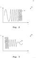
- an amplitude-time diagram 200 of an exemplary test signal 20 is shown.
- a signal is also known as a chirp signal, especially a positive chirp signal due to the increasing frequency.
- Fig. 3 illustrates an amplitude-time diagram 300 of another exemplary test signal 30.
- the Amplitude A decreases over time t
- the frequency of the exemplary test signal 30 also decreases over time t.
- the test signal 30 is a kind of a negative chirp signal.
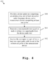
- Fig. 4 shows a flow chart 400 of the inventive method.
- a device under test comprising an antenna array and at least one active radio frequency device, and a measurement device comprising at least one probe are provided.
- a non-repeatable test signal is transmitted on each of at least two signal paths from the device under test.
- the test signal on each of the at least two signal paths is received with the aid of the at least one probe of the measurement device.
Landscapes
- Physics & Mathematics (AREA)
- Engineering & Computer Science (AREA)
- Computer Networks & Wireless Communication (AREA)
- Signal Processing (AREA)
- Electromagnetism (AREA)
- General Physics & Mathematics (AREA)
- Quality & Reliability (AREA)
- Variable-Direction Aerials And Aerial Arrays (AREA)
- Radio Transmission System (AREA)
Abstract
Description
- The invention relates to a system and a method for testing antenna arrays. Alternatively or additionally, the inventive system and method can be used for calibrating such antenna arrays.
- Generally, in times of an increasing number of wireless communication applications employing MIMO (Multiple Input Multiple Output) systems such as LTE (Long Term Evolution), there is a growing need of a testing system and a testing method for testing devices under test applying such systems, respectively the corresponding antenna arrays. In this context, especially the calibration of said antenna arrays is likewise increasingly gaining importance.
-
US 2016/0269093 A1 discloses a communication method and apparatus using analog and digital beamforming with respect to MIMO. Nevertheless, the aforementioned document does not consider testing or calibrating an antenna array, which is essential for ensuring the proper functioning of the device under test, respectively the wireless communication. - Accordingly, there is a need to provide a system and a method for testing and/or calibrating antenna arrays with special respect to wireless communication applications employing MIMO.
- This is solved by the features of claim 1 for the system and claim 9 for the method. The dependent claims contain further developments.
- According to a first aspect of the invention, a system for testing and/or calibrating an antenna array is provided. The system comprises a device under test comprising the antenna array and at least one active radio frequency device for transmitting a test signal being known and always the same or at least partially the same on each of at least two signal paths, and a measurement device comprising at least one probe for receiving the test signal on each of the at least two signal paths. In addition to this, said test signal is advantageously a non-repeatable one at least for the time of testing and/or calibrating.
- According to a first preferred implementation form of the first aspect, with respect to the test signal, at least one of amplitude, frequency, phase and spatial dependency changes over time. Advantageously, in the face of various delays occurring within the at least two signal paths, each of the at least two signal paths is unambiguously identifiable. In other words, within each of the at least two signal paths, the respective signal running from the at least one active radio frequency device to the corresponding antenna is delayed, wherein this delay may not be constant in comparison with the other signal paths. In this case, an unequivocal identification of each of the at least two signal paths is ensured. Further advantageously, the test signal is a chirp signal.
- According to a further preferred implementation form of the first aspect, the at least one probe measures the output of each of the at least two signal paths at a defined time interval.
- According to a further preferred implementation form of the first aspect, the measurement device collects the measurement data with respect to each of the at least two signal paths.
- According to a further preferred implementation form of the first aspect, the measurement device measures the time needed for changing with the position of the at least one probe from one of the at least two signal paths to another one of the at least two signal paths.
- According to a further preferred implementation form of the first aspect, on the basis of the corresponding measurements, the measurement device calculates the phase of each of the at least two signal paths and/or the phase difference between each pair of the at least two signal paths and/or the amplitude of each of at least two signal paths and/or the amplitude difference between each pair of the at least two signal paths. In other words, this calculation is performed based on measured data with respect to the output of each of the at least two signal paths, time needed for changing with position of the at least one probe from one of the at least two signal paths to another one of the at least two signal paths, and time interval for measurement of each of the at least two signal paths.
- According to a further preferred implementation form of the first aspect, each signal of at least one pair of the at least two signal paths partially or completely comprises the same signal portions.
- According to a further preferred implementation form of the first aspect, the system further comprises a switch matrix for changing the position of the at least one probe from one of the at least two signal paths to another one of the at least two signal paths.
- According to a second aspect of the invention, a method for testing and/or calibrating an antenna array is provided. The method uses a device under test comprising the antenna array and at least one active radio frequency device and a measurement device comprising at least one probe. Furthermore, the method comprises the steps of transmitting a test signal being known and always the same or at least partially the same on each of at least two signal paths from the device under test, and receiving the test signal on each of the at least two signal paths with the aid of the at least one probe of the measurement device. Advantageously, the test signal is a non-repeatable one at least for the time of testing and/or calibrating.
- According to a first preferred implementation form of the second aspect, with respect to the test signal, at least one of amplitude, frequency, phase and spatial dependency changes over time. Advantageously, in the face of various delays occurring within the at least two signal paths, each of the at least two signal paths is unambiguously identifiable. In other words, within each of the at least two signal paths, the respective signal running from the at least one active radio frequency device to the corresponding antenna is delayed, wherein this delay may not be constant in comparison with the other signal paths. In this case, an unequivocal identification of each of the at least two signal paths is ensured. Further advantageously, the test signal is a chirp signal. According to a further preferred implementation of the second aspect, the at least one probe measures the output of each of the at least two signal paths at a defined time interval.
- According to a further preferred implementation of the second aspect, the measurement device collects the measurement data with respect to each of the at least two signal paths.
- According to a further preferred implementation of the second aspect, the measurement device measures the time needed for changing with position of the at least one probe from one of the at least two signal paths to another one of the at least two signal paths.
- According to a further preferred implementation of the second aspect, on the basis of the corresponding measurements, the measurement device calculates the phase of each of the at least two signal paths and/or the phase difference between each pair of the at least two signal paths. In other words, this calculation is performed based on measured data with respect to the output of each of the at least two signal paths, time needed for changing with position of the at least one probe from one of the at least two signal paths to another one of the at least two signal paths, and time interval for measurement of each of the at least two signal paths.
- According to a further preferred implementation of the second aspect, each signal of at least one pair of the at least two signal paths partially or completely comprises the same signal portions.
- Exemplary embodiments of the invention are now further explained with respect to the drawings by way of example only, and not for limitation. In the drawings:
- Fig. 1
- shows a block diagram of an exemplary embodiment of the inventive system;
- Fig. 2
- shows an exemplary test signal, the frequency of which changes over time;
- Fig. 3
- shows an exemplary test signal, both the frequency and amplitude of which change over time; and
- Fig. 4
- shows a flow chart of an embodiment of the second aspect of the invention.
- From
Fig. 1 , an exemplary embodiment of theinventive system 100 can be seen. In this exemplary case, thesystem 100 comprises a device under test 1 comprising anantenna array 4, ameasurement device 2, preferably a vector network analyzer, comprising aprobe 3, and aswitch matrix 5. - The
antenna array 4 of the device under test 1 consists of fourantennas radio frequency device amplifier bandpass - Furthermore, each of the
antennas antenna array 4 of the device under test 1 is connected to theswitch matrix 5 coupled to theprobe 3 which is connected to themeasurement device 2, respectively to the vector network analyzer. Advantageously, due to theswitch matrix 5, switching between the signal paths for testing and/or calibrating theantenna array 4 is achieved without changing the physical position of theprobe 3. - For the purpose of testing the
antenna array 4 of the device under test 1, respectively for the purpose of calibrating the corresponding transceivers of each of theantennas antenna array 4 to maximize efficiency, a test signal is transmitted on each of the four signal paths. Preferably, said test signal is known, always the same, and a non-repeatable one, preferably a chirp signal or a kind thereof. In other words, with respect to the test signal, at least one of amplitude, frequency, and phase changes over time. - Moreover, the
probe 3 measures the output of each of the four signal paths with the aid of theswitch matrix 5 at a defined time interval. In order to provide an appropriate trigger condition for theswitch matrix 5, the non-repeatable test signal may be fed into each of the activeradio frequency devices switch matrix 5 itself via connection 9. Optionally, it may be advantageous to provide said trigger condition also for themeasurement device 2 viaconnection 10. As a consequence of this, with respect to thesystem 100, an absolute time basis is obtained, which ensures highly accurate measurements. - As it can be seen, the non-repeatable test signal can be transmitted via a rather low speed connection. Therefore, a cost-intensive implementation of radio frequency ports at the device under test are advantageously not necessary.
- In addition, it is to be pointed out that the above-mentioned connection 9 between the
switch matrix 5 and thetransceivers antenna array 4 of the device under test 1 is most time-saving and cost-efficient. - In this context, the test signal is directly implemented into the device under test 1 with the aid of hardware and/or software. Due to the fact that the test signal is known, always the same, and a non-repeatable one, the trigger condition, respectively the absolute time basis, can then be calculated with the aid of the
switch matrix 5 or with the aid of themeasurement device 2 or the combination thereof. - Moreover, after the output of each of the signal paths has been measured at a defined time interval as already mentioned above, the
measurement device 2 collects the corresponding measurement data, wherein themeasurement device 2 also measures the time needed for changing with the position of theprobe 3 from one of the signal paths to another one of the signal path, respectively the time needed for switching between the signal paths with the aid of theswitch matrix 5. - Generally, and in addition to this, it is to be mentioned that in order to advantageously speed up the measurements, if the measurement device comprises multiple input ports and multiple probes, the antennas of the antenna array can be grouped into different groups, wherein the number of groups is preferably equal to the number of input ports, respectively to the number of probes, of the measurement device. Thus, a part of the whole measurement can be parallelized, which allows for a shorter measuring time.
- Then, in order to complete the testing of the
antenna array 4, respectively the calibration of thecorresponding transceivers measurement device 2 calculates the phase of each of the signal paths and/or the phase difference between each pair of the signal paths. - Now, with respect to
Fig. 2 , an amplitude-time diagram 200 of anexemplary test signal 20 is shown. One can see that whereas the amplitude A of the test signal remains constant, the frequency of thetest signal 20 increases over time t. Such a signal is also known as a chirp signal, especially a positive chirp signal due to the increasing frequency. - Furthermore,
Fig. 3 illustrates an amplitude-time diagram 300 of anotherexemplary test signal 30. As it can be seen, in this case, whereas the Amplitude A decreases over time t, the frequency of theexemplary test signal 30 also decreases over time t. As a consequence of this, one might say that thetest signal 30 is a kind of a negative chirp signal. - Finally,
Fig. 4 shows aflow chart 400 of the inventive method. In a first step S40, a device under test comprising an antenna array and at least one active radio frequency device, and a measurement device comprising at least one probe are provided. In a second step S41, a non-repeatable test signal is transmitted on each of at least two signal paths from the device under test. Then, in a third step S42, the test signal on each of the at least two signal paths is received with the aid of the at least one probe of the measurement device.
Claims (15)
- A system (100) for testing and/or calibrating an antenna array (4), the system (100) comprising:a device under test (1) comprising the antenna array (4) and at least one active radio frequency device (6a, 6b, 6c, 6d) for transmitting a test signal (20, 30) being known and always the same or partially the same on each of at least two signal paths, anda measurement device (2) comprising at least one probe (3) for receiving the test signal (20, 30) on each of the at least two signal paths,wherein the test signal (20, 30) is a non-repeatable one for the time of testing and/or calibrating.
- The system (100) according to claim 1,
wherein with respect to the test signal (20, 30), at least one of amplitude, frequency, phase and spatial dependency changes over time. - The system (100) according to claim 1 or 2,
wherein the at least one probe (3) measures the output of each of the at least two signal paths at a defined time interval. - The system (100) according to any of the claims 1 to 3,
wherein the measurement device (2) collects the measurement data with respect to each of the at least two signal paths. - The system (100) according to any of the claims 1 to 4,
wherein the measurement device (2) measures the time needed for changing with the position of the at least one probe (3) from one of the at least two signal paths to another one of the at least two signal paths. - The system (100) according to any of the claims 1 to 5,
wherein on the basis of the corresponding measurements, the measurement device (2) calculates the phase of each of the at least two signal paths and/or the phase difference between each pair of the at least two signal paths and/or the amplitude of each of at least two signal paths and/or the amplitude difference between each pair of the at least two signal paths. - The system (100) according to any of the claims 1 to 6,
wherein each signal of at least one pair of the at least two signal paths partially or completely comprises the same signal portions. - The system (100) according to any of the claims 1 to 7,
wherein the system further comprises a switch matrix (5) for changing the position of the at least one probe (3) from one of the at least two signal paths to another one of the at least two signal paths. - A method for testing and/or calibrating an antenna array (4), the method using a device under test (1) comprising the antenna array (4) and at least one active radio frequency device (6a, 6b, 6c, 6d) and a measurement device (2) comprising at least one probe (3), the method comprising the steps of:transmitting a test signal (20, 30) being known and always the same or partially the same on each of at least two signal paths from the device under test (1), andreceiving the test signal (20, 30) on each of the at least two signal paths with the aid of the at least one probe (3) of the measurement device (2),wherein the test signal (20, 30) is a non-repeatable one for the time of testing and/or calibrating.
- The method according to claim 9,
wherein with respect to the test signal (20, 30), at least one of amplitude, frequency, phase and spatial dependency changes over time. - The method according to claim 9 or 10,
wherein the at least one probe (3) measures the output of each of the at least two signal paths at a defined time interval. - The method according to any of the claims 9 to 11, wherein the measurement device (2) collects the measurement data with respect to each of the at least two signal paths.
- The method according to any of the claims 9 to 12, wherein the measurement device (2) measures the time needed for changing with position of the at least one probe (3) from one of the at least two signal paths to another one of the at least two signal paths.
- The method according to any of the claims 9 to 13, wherein on the basis of the corresponding measurements, the measurement device (2) calculates the phase of each of the at least two signal paths and/or the phase difference between each pair of the at least two signal paths and/or the amplitude of each of at least two signal paths and/or the amplitude difference between each pair of the at least two signal paths.
- The method according to any of the claims 9 to 14, wherein each signal of at least one pair of the at least two signal paths partially or completely comprises the same signal portions.
Priority Applications (2)
| Application Number | Priority Date | Filing Date | Title |
|---|---|---|---|
| CN201710011102.7A CN107919922B (en) | 2016-10-06 | 2017-01-06 | System and method for testing antenna arrays |
| US15/400,314 US10079646B2 (en) | 2016-10-06 | 2017-01-06 | System and method for testing antenna arrays |
Applications Claiming Priority (1)
| Application Number | Priority Date | Filing Date | Title |
|---|---|---|---|
| EP16192520 | 2016-10-06 |
Publications (3)
| Publication Number | Publication Date |
|---|---|
| EP3306838A1 true EP3306838A1 (en) | 2018-04-11 |
| EP3306838B1 EP3306838B1 (en) | 2019-04-03 |
| EP3306838B8 EP3306838B8 (en) | 2019-06-05 |
Family
ID=57103897
Family Applications (1)
| Application Number | Title | Priority Date | Filing Date |
|---|---|---|---|
| EP16199018.9A Active EP3306838B8 (en) | 2016-10-06 | 2016-11-16 | System and method for testing antenna arrays |
Country Status (3)
| Country | Link |
|---|---|
| US (1) | US10079646B2 (en) |
| EP (1) | EP3306838B8 (en) |
| CN (1) | CN107919922B (en) |
Cited By (1)
| Publication number | Priority date | Publication date | Assignee | Title |
|---|---|---|---|---|
| CN115102640A (en) * | 2022-06-21 | 2022-09-23 | 深圳市易飞扬通信技术有限公司 | Product testing method and device, computer equipment and storage medium |
Families Citing this family (3)
| Publication number | Priority date | Publication date | Assignee | Title |
|---|---|---|---|---|
| CN109150331B (en) * | 2018-06-15 | 2021-05-11 | 上海卫星工程研究所 | Satellite multi-transmission channel index parallel automatic test system |
| CN111371513B (en) * | 2018-12-26 | 2024-04-09 | 是德科技股份有限公司 | Method and system for testing antenna array of device under test |
| EP3748374B8 (en) * | 2019-06-06 | 2023-02-15 | Rohde & Schwarz GmbH & Co. KG | System and method for calibrating radio frequency test chambers |
Citations (4)
| Publication number | Priority date | Publication date | Assignee | Title |
|---|---|---|---|---|
| US6046697A (en) * | 1997-09-05 | 2000-04-04 | Northern Telecom Limited | Phase control of transmission antennas |
| US20090153394A1 (en) * | 2007-12-17 | 2009-06-18 | Navarro Julio A | Method for accurate auto-calibration of phased array antennas |
| EP2722928A1 (en) * | 2012-10-17 | 2014-04-23 | Nxp B.V. | Testing and calibration of phased array antenna systems |
| US20160269093A1 (en) | 2012-05-10 | 2016-09-15 | Samsung Electronics Co., Ltd. | Communication method and apparatus using analog and digital hybrid beamforming |
Family Cites Families (3)
| Publication number | Priority date | Publication date | Assignee | Title |
|---|---|---|---|---|
| JP3651430B2 (en) * | 2001-09-17 | 2005-05-25 | 日本電気株式会社 | Array antenna calibration apparatus and calibration method |
| EP2372836B1 (en) * | 2010-03-18 | 2017-05-03 | Alcatel Lucent | Antenna array calibration |
| JP6252314B2 (en) * | 2014-03-31 | 2017-12-27 | 富士通株式会社 | Phased array transmitter, transceiver and radar equipment |
-
2016
- 2016-11-16 EP EP16199018.9A patent/EP3306838B8/en active Active
-
2017
- 2017-01-06 CN CN201710011102.7A patent/CN107919922B/en active Active
- 2017-01-06 US US15/400,314 patent/US10079646B2/en active Active
Patent Citations (4)
| Publication number | Priority date | Publication date | Assignee | Title |
|---|---|---|---|---|
| US6046697A (en) * | 1997-09-05 | 2000-04-04 | Northern Telecom Limited | Phase control of transmission antennas |
| US20090153394A1 (en) * | 2007-12-17 | 2009-06-18 | Navarro Julio A | Method for accurate auto-calibration of phased array antennas |
| US20160269093A1 (en) | 2012-05-10 | 2016-09-15 | Samsung Electronics Co., Ltd. | Communication method and apparatus using analog and digital hybrid beamforming |
| EP2722928A1 (en) * | 2012-10-17 | 2014-04-23 | Nxp B.V. | Testing and calibration of phased array antenna systems |
Cited By (1)
| Publication number | Priority date | Publication date | Assignee | Title |
|---|---|---|---|---|
| CN115102640A (en) * | 2022-06-21 | 2022-09-23 | 深圳市易飞扬通信技术有限公司 | Product testing method and device, computer equipment and storage medium |
Also Published As
| Publication number | Publication date |
|---|---|
| EP3306838B1 (en) | 2019-04-03 |
| CN107919922A (en) | 2018-04-17 |
| EP3306838B8 (en) | 2019-06-05 |
| US10079646B2 (en) | 2018-09-18 |
| US20180102856A1 (en) | 2018-04-12 |
| CN107919922B (en) | 2021-09-28 |
Similar Documents
| Publication | Publication Date | Title |
|---|---|---|
| CN101915909B (en) | Implementing method for calibrating amplitude and phase of system receiving channel | |
| JP6886984B2 (en) | Wireless performance test method for MIMO wireless terminals | |
| CN109952513A (en) | A kind of method and school survey device of the survey of phased array school | |
| US10079646B2 (en) | System and method for testing antenna arrays | |
| CN110873826B (en) | Antenna array test circuit, phased antenna array and method for testing phased antenna array | |
| GB2539783A (en) | System and method for test and/or calibration of multi-channel RF communication devices | |
| CN108614247A (en) | A kind of secondary radar channel calibration method | |
| US20180109330A1 (en) | Multi-antenna noise power measuring method and apparatus | |
| KR101706629B1 (en) | power calibration method for MIMO-OFDM transmitter | |
| CN113805042A (en) | Time delay measurement device and test method | |
| US9509346B2 (en) | Circuit and method for a circuit | |
| US10945142B2 (en) | Wireless channel sounder with fast measurement speed and wide dynamic range | |
| CN108631886B (en) | Measurement system and method with digital dead space | |
| CN109103600B (en) | System and method for phase calibration of antenna arrays | |
| US8477866B2 (en) | Calibration method for Tx/Rx path characteristic of channel sounder | |
| US10680327B2 (en) | Calibration system and method for calibrating an antenna array | |
| CN108075841B (en) | Test equipment and methods for testing a device under test with respect to its beamforming behavior | |
| WO2019061173A1 (en) | Method, device and system for calibrating array antennas | |
| US12487263B2 (en) | UWB antenna and BLE antenna performance test system | |
| EP3968045B1 (en) | Imaging system and method for material characterization of a sample | |
| US20250338152A1 (en) | Signal generator system and method for calibrating a signal generator system | |
| US20250217063A1 (en) | Test instrument with integrated model data base | |
| CN102340786A (en) | Method and device for beamforming calibration and capability test | |
| WO2024074200A1 (en) | Distance determination between two bluetooth devices | |
| Ataman et al. | Transmitter and Receiver Mismatch Measurement for MIMO RF Antennas via Simple Power Monitors |
Legal Events
| Date | Code | Title | Description |
|---|---|---|---|
| STAA | Information on the status of an ep patent application or granted ep patent |
Free format text: STATUS: EXAMINATION IS IN PROGRESS |
|
| PUAI | Public reference made under article 153(3) epc to a published international application that has entered the european phase |
Free format text: ORIGINAL CODE: 0009012 |
|
| 17P | Request for examination filed |
Effective date: 20170616 |
|
| AK | Designated contracting states |
Kind code of ref document: A1 Designated state(s): AL AT BE BG CH CY CZ DE DK EE ES FI FR GB GR HR HU IE IS IT LI LT LU LV MC MK MT NL NO PL PT RO RS SE SI SK SM TR |
|
| AX | Request for extension of the european patent |
Extension state: BA ME |
|
| GRAP | Despatch of communication of intention to grant a patent |
Free format text: ORIGINAL CODE: EPIDOSNIGR1 |
|
| STAA | Information on the status of an ep patent application or granted ep patent |
Free format text: STATUS: GRANT OF PATENT IS INTENDED |
|
| INTG | Intention to grant announced |
Effective date: 20181119 |
|
| GRAS | Grant fee paid |
Free format text: ORIGINAL CODE: EPIDOSNIGR3 |
|
| GRAA | (expected) grant |
Free format text: ORIGINAL CODE: 0009210 |
|
| STAA | Information on the status of an ep patent application or granted ep patent |
Free format text: STATUS: THE PATENT HAS BEEN GRANTED |
|
| AK | Designated contracting states |
Kind code of ref document: B1 Designated state(s): AL AT BE BG CH CY CZ DE DK EE ES FI FR GB GR HR HU IE IS IT LI LT LU LV MC MK MT NL NO PL PT RO RS SE SI SK SM TR |
|
| REG | Reference to a national code |
Ref country code: GB Ref legal event code: FG4D |
|
| REG | Reference to a national code |
Ref country code: CH Ref legal event code: EP Ref country code: AT Ref legal event code: REF Ref document number: 1117050 Country of ref document: AT Kind code of ref document: T Effective date: 20190415 |
|
| RBV | Designated contracting states (corrected) |
Designated state(s): AL AT BE BG CY CZ DE DK EE ES FI FR GB GR HR HU IS IT LT LU LV MC MK MT NL NO PL PT RO RS SE SI SK SM TR |
|
| REG | Reference to a national code |
Ref country code: DE Ref legal event code: R096 Ref document number: 602016011824 Country of ref document: DE |
|
| REG | Reference to a national code |
Ref country code: IE Ref legal event code: FG4D |
|
| REG | Reference to a national code |
Ref country code: CH Ref legal event code: PK Free format text: DIE BENENNUNG CH/LI WURDE VOR DER ERTEILUNG ZURUECKGENOMMEN. |
|
| REG | Reference to a national code |
Ref country code: NL Ref legal event code: MP Effective date: 20190403 |
|
| REG | Reference to a national code |
Ref country code: LT Ref legal event code: MG4D |
|
| REG | Reference to a national code |
Ref country code: AT Ref legal event code: MK05 Ref document number: 1117050 Country of ref document: AT Kind code of ref document: T Effective date: 20190403 |
|
| PG25 | Lapsed in a contracting state [announced via postgrant information from national office to epo] |
Ref country code: NL Free format text: LAPSE BECAUSE OF FAILURE TO SUBMIT A TRANSLATION OF THE DESCRIPTION OR TO PAY THE FEE WITHIN THE PRESCRIBED TIME-LIMIT Effective date: 20190403 |
|
| PG25 | Lapsed in a contracting state [announced via postgrant information from national office to epo] |
Ref country code: ES Free format text: LAPSE BECAUSE OF FAILURE TO SUBMIT A TRANSLATION OF THE DESCRIPTION OR TO PAY THE FEE WITHIN THE PRESCRIBED TIME-LIMIT Effective date: 20190403 Ref country code: SE Free format text: LAPSE BECAUSE OF FAILURE TO SUBMIT A TRANSLATION OF THE DESCRIPTION OR TO PAY THE FEE WITHIN THE PRESCRIBED TIME-LIMIT Effective date: 20190403 Ref country code: PT Free format text: LAPSE BECAUSE OF FAILURE TO SUBMIT A TRANSLATION OF THE DESCRIPTION OR TO PAY THE FEE WITHIN THE PRESCRIBED TIME-LIMIT Effective date: 20190803 Ref country code: AL Free format text: LAPSE BECAUSE OF FAILURE TO SUBMIT A TRANSLATION OF THE DESCRIPTION OR TO PAY THE FEE WITHIN THE PRESCRIBED TIME-LIMIT Effective date: 20190403 Ref country code: HR Free format text: LAPSE BECAUSE OF FAILURE TO SUBMIT A TRANSLATION OF THE DESCRIPTION OR TO PAY THE FEE WITHIN THE PRESCRIBED TIME-LIMIT Effective date: 20190403 Ref country code: LT Free format text: LAPSE BECAUSE OF FAILURE TO SUBMIT A TRANSLATION OF THE DESCRIPTION OR TO PAY THE FEE WITHIN THE PRESCRIBED TIME-LIMIT Effective date: 20190403 Ref country code: FI Free format text: LAPSE BECAUSE OF FAILURE TO SUBMIT A TRANSLATION OF THE DESCRIPTION OR TO PAY THE FEE WITHIN THE PRESCRIBED TIME-LIMIT Effective date: 20190403 Ref country code: NO Free format text: LAPSE BECAUSE OF FAILURE TO SUBMIT A TRANSLATION OF THE DESCRIPTION OR TO PAY THE FEE WITHIN THE PRESCRIBED TIME-LIMIT Effective date: 20190703 Ref country code: CZ Free format text: LAPSE BECAUSE OF FAILURE TO SUBMIT A TRANSLATION OF THE DESCRIPTION OR TO PAY THE FEE WITHIN THE PRESCRIBED TIME-LIMIT Effective date: 20190403 |
|
| PG25 | Lapsed in a contracting state [announced via postgrant information from national office to epo] |
Ref country code: RS Free format text: LAPSE BECAUSE OF FAILURE TO SUBMIT A TRANSLATION OF THE DESCRIPTION OR TO PAY THE FEE WITHIN THE PRESCRIBED TIME-LIMIT Effective date: 20190403 Ref country code: GR Free format text: LAPSE BECAUSE OF FAILURE TO SUBMIT A TRANSLATION OF THE DESCRIPTION OR TO PAY THE FEE WITHIN THE PRESCRIBED TIME-LIMIT Effective date: 20190704 Ref country code: PL Free format text: LAPSE BECAUSE OF FAILURE TO SUBMIT A TRANSLATION OF THE DESCRIPTION OR TO PAY THE FEE WITHIN THE PRESCRIBED TIME-LIMIT Effective date: 20190403 Ref country code: BG Free format text: LAPSE BECAUSE OF FAILURE TO SUBMIT A TRANSLATION OF THE DESCRIPTION OR TO PAY THE FEE WITHIN THE PRESCRIBED TIME-LIMIT Effective date: 20190703 Ref country code: LV Free format text: LAPSE BECAUSE OF FAILURE TO SUBMIT A TRANSLATION OF THE DESCRIPTION OR TO PAY THE FEE WITHIN THE PRESCRIBED TIME-LIMIT Effective date: 20190403 |
|
| PG25 | Lapsed in a contracting state [announced via postgrant information from national office to epo] |
Ref country code: IS Free format text: LAPSE BECAUSE OF FAILURE TO SUBMIT A TRANSLATION OF THE DESCRIPTION OR TO PAY THE FEE WITHIN THE PRESCRIBED TIME-LIMIT Effective date: 20190803 Ref country code: AT Free format text: LAPSE BECAUSE OF FAILURE TO SUBMIT A TRANSLATION OF THE DESCRIPTION OR TO PAY THE FEE WITHIN THE PRESCRIBED TIME-LIMIT Effective date: 20190403 |
|
| REG | Reference to a national code |
Ref country code: DE Ref legal event code: R097 Ref document number: 602016011824 Country of ref document: DE |
|
| PG25 | Lapsed in a contracting state [announced via postgrant information from national office to epo] |
Ref country code: DK Free format text: LAPSE BECAUSE OF FAILURE TO SUBMIT A TRANSLATION OF THE DESCRIPTION OR TO PAY THE FEE WITHIN THE PRESCRIBED TIME-LIMIT Effective date: 20190403 Ref country code: SK Free format text: LAPSE BECAUSE OF FAILURE TO SUBMIT A TRANSLATION OF THE DESCRIPTION OR TO PAY THE FEE WITHIN THE PRESCRIBED TIME-LIMIT Effective date: 20190403 Ref country code: RO Free format text: LAPSE BECAUSE OF FAILURE TO SUBMIT A TRANSLATION OF THE DESCRIPTION OR TO PAY THE FEE WITHIN THE PRESCRIBED TIME-LIMIT Effective date: 20190403 Ref country code: EE Free format text: LAPSE BECAUSE OF FAILURE TO SUBMIT A TRANSLATION OF THE DESCRIPTION OR TO PAY THE FEE WITHIN THE PRESCRIBED TIME-LIMIT Effective date: 20190403 |
|
| PLBE | No opposition filed within time limit |
Free format text: ORIGINAL CODE: 0009261 |
|
| STAA | Information on the status of an ep patent application or granted ep patent |
Free format text: STATUS: NO OPPOSITION FILED WITHIN TIME LIMIT |
|
| PG25 | Lapsed in a contracting state [announced via postgrant information from national office to epo] |
Ref country code: SM Free format text: LAPSE BECAUSE OF FAILURE TO SUBMIT A TRANSLATION OF THE DESCRIPTION OR TO PAY THE FEE WITHIN THE PRESCRIBED TIME-LIMIT Effective date: 20190403 Ref country code: IT Free format text: LAPSE BECAUSE OF FAILURE TO SUBMIT A TRANSLATION OF THE DESCRIPTION OR TO PAY THE FEE WITHIN THE PRESCRIBED TIME-LIMIT Effective date: 20190403 |
|
| 26N | No opposition filed |
Effective date: 20200106 |
|
| PG25 | Lapsed in a contracting state [announced via postgrant information from national office to epo] |
Ref country code: TR Free format text: LAPSE BECAUSE OF FAILURE TO SUBMIT A TRANSLATION OF THE DESCRIPTION OR TO PAY THE FEE WITHIN THE PRESCRIBED TIME-LIMIT Effective date: 20190403 |
|
| PG25 | Lapsed in a contracting state [announced via postgrant information from national office to epo] |
Ref country code: SI Free format text: LAPSE BECAUSE OF FAILURE TO SUBMIT A TRANSLATION OF THE DESCRIPTION OR TO PAY THE FEE WITHIN THE PRESCRIBED TIME-LIMIT Effective date: 20190403 |
|
| PG25 | Lapsed in a contracting state [announced via postgrant information from national office to epo] |
Ref country code: LU Free format text: LAPSE BECAUSE OF NON-PAYMENT OF DUE FEES Effective date: 20191116 Ref country code: MC Free format text: LAPSE BECAUSE OF FAILURE TO SUBMIT A TRANSLATION OF THE DESCRIPTION OR TO PAY THE FEE WITHIN THE PRESCRIBED TIME-LIMIT Effective date: 20190403 |
|
| REG | Reference to a national code |
Ref country code: BE Ref legal event code: MM Effective date: 20191130 |
|
| PG25 | Lapsed in a contracting state [announced via postgrant information from national office to epo] |
Ref country code: BE Free format text: LAPSE BECAUSE OF NON-PAYMENT OF DUE FEES Effective date: 20191130 |
|
| PG25 | Lapsed in a contracting state [announced via postgrant information from national office to epo] |
Ref country code: CY Free format text: LAPSE BECAUSE OF FAILURE TO SUBMIT A TRANSLATION OF THE DESCRIPTION OR TO PAY THE FEE WITHIN THE PRESCRIBED TIME-LIMIT Effective date: 20190403 |
|
| PG25 | Lapsed in a contracting state [announced via postgrant information from national office to epo] |
Ref country code: HU Free format text: LAPSE BECAUSE OF FAILURE TO SUBMIT A TRANSLATION OF THE DESCRIPTION OR TO PAY THE FEE WITHIN THE PRESCRIBED TIME-LIMIT; INVALID AB INITIO Effective date: 20161116 Ref country code: MT Free format text: LAPSE BECAUSE OF FAILURE TO SUBMIT A TRANSLATION OF THE DESCRIPTION OR TO PAY THE FEE WITHIN THE PRESCRIBED TIME-LIMIT Effective date: 20190403 |
|
| PG25 | Lapsed in a contracting state [announced via postgrant information from national office to epo] |
Ref country code: MK Free format text: LAPSE BECAUSE OF FAILURE TO SUBMIT A TRANSLATION OF THE DESCRIPTION OR TO PAY THE FEE WITHIN THE PRESCRIBED TIME-LIMIT Effective date: 20190403 |
|
| P01 | Opt-out of the competence of the unified patent court (upc) registered |
Effective date: 20230525 |
|
| PGFP | Annual fee paid to national office [announced via postgrant information from national office to epo] |
Ref country code: DE Payment date: 20251118 Year of fee payment: 10 |
|
| PGFP | Annual fee paid to national office [announced via postgrant information from national office to epo] |
Ref country code: GB Payment date: 20251120 Year of fee payment: 10 |
|
| PGFP | Annual fee paid to national office [announced via postgrant information from national office to epo] |
Ref country code: FR Payment date: 20251125 Year of fee payment: 10 |