EP3306802A1 - Synchrones steuerverfahren für schnittstelle und optimierung einer piezoelektrischen energiegewinnungsvorrichtung, steuerschaltung und schnittstellenschaltung - Google Patents
Synchrones steuerverfahren für schnittstelle und optimierung einer piezoelektrischen energiegewinnungsvorrichtung, steuerschaltung und schnittstellenschaltung Download PDFInfo
- Publication number
- EP3306802A1 EP3306802A1 EP16306338.1A EP16306338A EP3306802A1 EP 3306802 A1 EP3306802 A1 EP 3306802A1 EP 16306338 A EP16306338 A EP 16306338A EP 3306802 A1 EP3306802 A1 EP 3306802A1
- Authority
- EP
- European Patent Office
- Prior art keywords
- generator
- voltage
- cyclic
- energy
- inductor
- Prior art date
- Legal status (The legal status is an assumption and is not a legal conclusion. Google has not performed a legal analysis and makes no representation as to the accuracy of the status listed.)
- Granted
Links
- 238000000034 method Methods 0.000 title claims abstract description 74
- 238000003306 harvesting Methods 0.000 title claims abstract description 26
- 230000001360 synchronised effect Effects 0.000 title claims abstract description 19
- 238000005457 optimization Methods 0.000 title description 5
- 230000003466 anti-cipated effect Effects 0.000 claims abstract description 36
- 238000006073 displacement reaction Methods 0.000 claims abstract description 29
- 230000005284 excitation Effects 0.000 claims abstract description 19
- 238000007599 discharging Methods 0.000 claims abstract description 18
- 230000001960 triggered effect Effects 0.000 claims abstract description 12
- 238000000605 extraction Methods 0.000 claims abstract description 11
- 125000004122 cyclic group Chemical group 0.000 claims description 34
- 230000010363 phase shift Effects 0.000 claims description 30
- 238000003860 storage Methods 0.000 claims description 27
- 208000028659 discharge Diseases 0.000 claims description 13
- 238000012546 transfer Methods 0.000 claims description 11
- 238000004804 winding Methods 0.000 claims description 4
- 230000003111 delayed effect Effects 0.000 description 7
- 230000008878 coupling Effects 0.000 description 6
- 238000010168 coupling process Methods 0.000 description 6
- 238000005859 coupling reaction Methods 0.000 description 6
- 230000006870 function Effects 0.000 description 6
- 239000000463 material Substances 0.000 description 5
- 230000001133 acceleration Effects 0.000 description 4
- 230000007423 decrease Effects 0.000 description 4
- 238000005516 engineering process Methods 0.000 description 4
- 230000014509 gene expression Effects 0.000 description 4
- 238000004088 simulation Methods 0.000 description 4
- 230000026683 transduction Effects 0.000 description 4
- 238000010361 transduction Methods 0.000 description 4
- 238000013016 damping Methods 0.000 description 3
- 230000003071 parasitic effect Effects 0.000 description 3
- 239000003990 capacitor Substances 0.000 description 2
- 238000001514 detection method Methods 0.000 description 2
- 230000000630 rising effect Effects 0.000 description 2
- 241001124569 Lycaenidae Species 0.000 description 1
- 241001465754 Metazoa Species 0.000 description 1
- 230000006978 adaptation Effects 0.000 description 1
- 238000012512 characterization method Methods 0.000 description 1
- 238000004891 communication Methods 0.000 description 1
- 238000002059 diagnostic imaging Methods 0.000 description 1
- 238000010586 diagram Methods 0.000 description 1
- 230000000694 effects Effects 0.000 description 1
- 230000005611 electricity Effects 0.000 description 1
- 238000011156 evaluation Methods 0.000 description 1
- 239000012530 fluid Substances 0.000 description 1
- 230000007774 longterm Effects 0.000 description 1
- 238000002595 magnetic resonance imaging Methods 0.000 description 1
- 238000004519 manufacturing process Methods 0.000 description 1
- 238000004377 microelectronic Methods 0.000 description 1
- 238000012806 monitoring device Methods 0.000 description 1
- 230000010349 pulsation Effects 0.000 description 1
Images


Classifications
-
- H—ELECTRICITY
- H02—GENERATION; CONVERSION OR DISTRIBUTION OF ELECTRIC POWER
- H02N—ELECTRIC MACHINES NOT OTHERWISE PROVIDED FOR
- H02N2/00—Electric machines in general using piezoelectric effect, electrostriction or magnetostriction
- H02N2/18—Electric machines in general using piezoelectric effect, electrostriction or magnetostriction producing electrical output from mechanical input, e.g. generators
- H02N2/181—Circuits; Control arrangements or methods
Definitions
- Invention pertains to an electronic circuit that performs the function of interfacing a piezoelectric generator with an electrical load or a component for storing an electrical energy by this generator.
- Invention also discloses a method for optimizing, possibly in real-time, the control parameters of a SECE method in function of a mismatch between the actual excitation frequency of the piezoelectric generator and its natural mechanical frequency. This method applies to SECE method such phase shifting only, or with anticipated interruption t2' only, or with both of them.
- Invention also discloses a device implementing such a synchronization method, enabling a particularly simple, efficient and robust operation.
- Electronic devices or devices comprising an electronic part are known, which are to operate autonomously during an extended duration without connection to an external electrical energy, or at least longer than would be enabled by the energy initially stored onboard.
- Such a device may be a low consumer long term device to be implanted in a human or animal body, where it is difficult to provide an electrical charging connection. It may also pertain to measure or detection sensors with wireless communication, to be dispatched in extended areas, such as radio receivers or environment sensors. Other devices are relevant, such as wearable devices or smart clothes, or monitoring device, or a positioning beacon.
- Such mechanical energy may be harvested through different kinds of converters, also called transducers.
- Electromagnetic transduction is known, but is difficult to miniaturize and may have incompatibilities, for examples as with medical imaging technologies such as Magnetic Resonance Imaging.
- Electrostatic transduction uses charges and discharges created by a displacement or deformation, like a variable capacity condenser. Though miniaturization is possible, complex electronics are needed for managing charging and discharging stages of transducers.
- Piezoelectric transduction uses efforts or deformations of a material with piezoelectric properties, which directly convert such electromechanical energy into electrical energy. This kind of transduction is well suited to miniaturization.
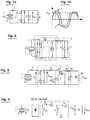
- FIGURE 1a shows an example of a known circuit for harvesting electrical energy from a piezoelectric transducer Pz, when deformed by an alternative displacement X.
- Interface circuit comprises a diodes bridge that receives an alternative input voltage V from the transducer, et converts it into a direct current for charging an accumulator Cr under voltage V DC .
- FIGURE 1b shows, according to time t, the curve of piezoelectric voltage V, superposed with the curve of displacement X. As soon as piezo voltage V exceeds voltage V DC of the accumulator, in the flat part of the V curve, further electrical energy is stored into the accumulator Cr.
- FIGURE 3 shows another circuit working with the same principle for charging a storage component Cf, with the same kind of SECE synchronous controlling method, as disclosed in paper from Lefecute et al., "piezoelectric "energy harvesting device optimization by synchronous electric charge extraction", in Journal of Intelligent Material Systems and Structures, Vol. 16, N°10, 865-876, 2005 .
- inductor is a coupled inductor L producing a voltage transformer.
- Electronic switch T is controlled by a voltage signal V G and is disposed in series in the same branch as the primary winding of coupled inductor L.
- FIGURE 4 shows still another kind of interface circuit using SECE, disclosed in the book from Thorsten Hehn, "CMOS Circuits for Piezoelectric Energy Harvesters", Springer Series in Advanced Microelectronics, Volume 38 2015 .
- inductor L is arranged in series between diodes bridge end storage component Cbuf.
- One switch S2 is connected in series with inductor L.
- Two switches S1 and S3 are connected in parallel with the diodes bridge, one on each side of the inductor L.
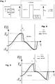
- FIGURE 5 Such a synchronized control technology SECE is illustrated in FIGURE 5 , where the top curve shows the variations of piezo voltage V(t), and the bottom curve shows the concurrent displacement X(t) within the piezoelectric generator.
- Control switch (or switches) is synchronized with the absolute maxima V M and - V M of piezo voltage V.
- switch T is commanded to be kept open while piezo voltage V(t) is rising and electrical energy is stored in inductor L.
- maximum piezoelectric voltage V M is detected by a peak detector, at time t1, switch T is closed so as to allow electrical energy to leave inductor L as current I D toward storage component Cf.
- switch T is opened anew and absolute value of voltage V start rising again, until the next maxima -V M .
- such method is applied to a device that comprises a circuitry as known in the prior art, such as in the documents cited here above.
- the stage of discharging is at a transfer time which is in offset from the peak time by a given non-zero phase shift.
- Such method comprises controlling said electronic switch so as to trigger the discharge stage in a synchronized manner which is calculated according to a peak time, at which a maximum value is reached by the absolute value of input voltage), or of the piezo generator's displacement), or of the electrical converted energy produced by the piezo generator
- said method is characterized in that the stage of discharging is triggered at a transfer time which is in offset from the peak time by a given non-zero phase shift.
- such method advantageously comprises the feature that the stage of discharging is triggered at an anticipated time which takes place before a zero-crossing time at which the input voltage) crosses zero volt.
- such feature may be implemented as known in the prior art such as in document DE 10 2013 105 585 .
- This feature enables the interface circuit to follow the optimal working point of the system, for which a maximal electrical power is produced, along a working duration where the generator is excited at a frequency that differs from its mechanical resonance frequency, even when its frequency is not constant.
- an optimized anticipated SECE method for controlling an interface circuit within an energy harvesting circuit, wherein said energy harvesting circuit comprises at least one piezoelectric generator arranged for receiving a cyclic mechanical energy and convert it into a cyclic electrical converted energy, said interface circuit is operatively connected for receiving said electrical converted energy as a cyclic input voltage and for extracting at least part of it as an output voltage adapted for storage into a storage circuitry, said interface circuit comprising at least one inductor and at least one electronic switch controlled by a control circuitry so as to alternatively trigger, when successively changing its state:
- Such method comprises controlling said electronic switch so as to:
- such an optimized anticipated SECE is characterized in that the anticipated time is calculated according to a value of the difference between the frequency of an actual cyclic excitation received by the piezo generator and the natural mechanical frequency of said piezo generator.
- a device comprising an interface circuit within or for an energy harvesting device that comprises at least one piezoelectric generator arranged for receiving a cyclic mechanical energy and convert it into a cyclic electrical converted energy, said interface circuit being arranged for receiving said electrical converted energy as a cyclic input voltage and for extracting at least part of said energy as an output voltage adapted for storage into a storage circuitry, said interface circuit comprising at least one inductor and at least one electronic switch controlled by a control circuitry so as to alternatively trigger, when successively changing its state:
- said device is characterized in that said control circuitry is arranged, hardwired and/or soft wired, for implementing a method as exposed herein, according to the first aspect or to the second aspect.
- Invention thus enables to optimize the electrical energy produced by a piezoelectric generator, for a direct consumption and/or for a storage in a intermediary storage device for a subsequent consumption, such as an accumulator, or a capacitor or a super-capacitor.
- invention When compared with the prior art, invention enables a better trade-off for a low consumption and/or a good robustness and/or a high efficiency and/or a wide efficiency range, especially in terms of frequency bandwidth.
- an interface circuit is connected between the terminals of the piezoelectric generator Pz, for receiving piezoelectric voltage V produced by said generator when alternatively excited, in this example along a direction "x".
- Such piezoelectric voltage V is received through a rectifier circuit, which is shown here as included in the interface circuit.
- the "interface circuit” could also be defined as not including the rectifier circuit.
- Interface circuit comprises an extraction circuit, working in a synchronous manner with the piezoelectric generator Pz, controlled by a synchronization controlling circuit as detailed here.
- This interface circuit together with the synchronization controlling circuit, provides a circuit for energy managing of the piezoelectric generator Pz.
- V out Electrical energy is provided by the interface circuit as an output voltage V out , through its connection to the terminals of the storage device or component, which here always implicitly includes the case of a direct consumer electrical load.
- harvesting circuit is realized as the circuit of FIGURE 3 , or similarly, but the controlling voltage V G is controlled differently.
- invention is applied to circuits identical or similar to the circuits shown in FIGURE 2 or FIGURE 4 , or other kind of circuits producing the same functional components shown in FIGURE 7
- Electronics within the interface circuit, and more specifically within the synchronization controlling circuit preferably works under a voltage of a few volts to a few tenths of volts, while consuming a very low power, as power levels of piezoelectric generators are typically found within a power range of a few tenths of nanowatts and a few tenths of microwatts.
- generated power is between 10 ⁇ W and 10 mW while piezoelectric maximum voltage V M is between 1 V to around 200 V, Piezoelectric generator is mechanically excited at a frequency between 0.1 Hz and 10 kHz, with an acceleration between 0.01 m/s 2 and 50 m/s 2 .
- first aspect of the invention comprises controlling the electronic switch by the synchronization controlling circuit so as to trigger the discharge stage in a synchronized manner which is calculated according to a peak time (t1), at which a maximum value V M is reached by the absolute value of input voltage (V(t)), or of the piezo generator's displacement X(t), which here correspond to the electrical converted energy produced by the piezo generator.
- a peak time (t1) at which a maximum value V M is reached by the absolute value of input voltage (V(t)), or of the piezo generator's displacement X(t), which here correspond to the electrical converted energy produced by the piezo generator.
- the stage of discharging is triggered at a transfer time (t1') which is in offset from the peak time (t1) by a given non-zero phase shift ( ⁇ ), negative or positive.
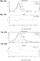
- FIGURE 8 illustrates an exemplary embodiment of invention with a delayed phase shift for charging time, with the voltage at input of interface circuit V(t) is referenced SECE ⁇ +. It can be seen that charging time is triggered at a time t1' which occurs later than the peak time t1. Thus, the curve SECE ⁇ + of piezo voltage V(t) start its sudden descent later than the curve of the prior art SECE method.
- FIGURE 9 illustrates another exemplary embodiment of invention with an anticipated phase shift for charging time, with the voltage at input of interface circuit V(t) is referenced SECE ⁇ -. It can be seen that charging time is triggered at a time t1' which occurs before the peak time t1. Thus, the curve SECE ⁇ - of piezo voltage V(t) start its sudden descent earlier than the curve of the prior art SECE method.
- FIGURE 10 and FIGURE 11 illustrate embodiments where the stage of discharging is triggered at an anticipated time t2' which takes place before a zero-crossing time t2 at which the input voltage V(t) crosses zero volt.
- the anticipated time t2' is chosen as the time at which the input voltage V(t) reaches an interruption voltage defined as a given fraction ⁇ of the maximum value V M of said input voltage.
- FIGURE 10 illustrates an exemplary embodiment of invention with a delayed phase shift of charging time, and which furthermore includes an anticipated interruption time.
- Charging time is delayed, with t1' occurring after t1.
- Interruption time is anticipated at t2', occurring when the curve SECE ⁇ +ai crosses the voltage value of ⁇ .V M .
- the abrupt descent of V(t) interrupt before crossing the zero volts value.
- FIGURE 11 illustrates another exemplary embodiment of invention with an anticipated phase shift of charging time, charging time being anticipated with t1' occurring before t1, and which also includes an anticipated interruption time t2'.
- FIGURE 12a and FIGURE 12b A numerical model has been established, that produces a numerical evaluation of the interface operation and its results. This numerical modeling has been computed on the basis of a piezoelectric harvesting device schematically illustrated in FIGURE 12a and FIGURE 12b , when considered as an electromechanical resonator with one degree of freedom.
- FIGURE 12a shows the device from a mechanical point of view
- FIGURE 12b from the electrical point of view
- the "electrical circuit” block here represents the interface circuit
- Piezoelectric generator or transducer
- ⁇ electromechanical force factor
- Cp its natural capacity
- Rp parasitic leakage resistance
- Ap 1/Rp thus representing the parasitic conductance
- M is the equivalent dynamical mass
- D is the damping coefficient
- K represents the mechanical stiffness of the device when the piezoelectric element Pz is in short circuit.
- An external vibrating source produces the displacement y(t) of the housing H that encloses the system (the whole system or at least the piezo generator), with respect to the Galilean referential.
- This housing displacement y(t) induces a relative displacement x(t) between the inertial mass M and the housing H.
- changes of constraints and deformation are applied to the piezoelectric material Pz. This creates a current i(t) and a voltage V(t) between the terminal electrodes of the piezoelectric element Pz.
- k 2 is the squared effective coupling factor of the harvester structure
- ⁇ M is the parasitic damping
- ⁇ E is the electrical damping.
- interface circuit is considered to be realized in the same form as the circuit of FIGURE 3 , extracted from a publication from the same inventor.
- Electronic switch T is controlled through voltage V G which is produced by an electronic controlling circuit, not shown in FIGURE 3 , so as to extract electrical energy form the energy produced by the piezoelectric element Pz, through controlling two parameters:
- V M is the peak piezoelectric voltage
- FIGURE 13 shows an example of a resulting curve, simulated through this model with a delayed phase shift ( ⁇ is positive) of charging time and anticipated interruption time (discharge stage extend only between V M and ( ⁇ .V M with ⁇ >0).
- V M ⁇ C p x M cos ⁇ 2 1 + ⁇
- this relation may then be used as a control law for finding the values of ⁇ and ⁇ that will produce the highest output power P , or even an output power P that is adjusted to a given value beneath the highest value, or even a specific frequency bandwidth which is selected to harvest power.
- an analytical solution may be searched in some embodiments, while it may happen that on one exists.
- analytic expressions of the optimal control laws for ⁇ and ⁇ as a function of angular frequency ⁇ are found by searching the zeroes of partial derivatives of power P with respect to ⁇ and ⁇ .
- optimal control laws ⁇ ( ⁇ ) and ⁇ ( ⁇ ) for a maximized harvested power P are computed by numerical solving, whatever the various parameters of the device, for example by a known solver and/or with a software like Matlab.
- a process 10 of designing or programming a device according to the invention comprises a step 101 of:
- this process 100 then comprises a step 102 of computing the control parameters ⁇ and ⁇ to be used for controlling electronic switch of device.
- Said computed parameters are then memorized as phase shift ⁇ and interruption fraction ⁇ , to be applied during the synchronization control of said device.
- optimizing or adjusting output power is also proposed as a real-time servo-control process for such a device.
- the device executes a programmed process 11 that comprises one or several iterations of the following steps:
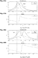
- FIGURE 15 shows the results of a numerical simulation of a SECE controlling method according to the invention, with a harvesting device modeled according to FIGURE 12 that presents a first set of generator parameters.
- piezoelectric generator is supposed to exhibits the following parameters
- horizontal axis shows the ratio of actual excitation frequency on natural frequency, i.e. ⁇ / ⁇ 0 .
- SECE ⁇ gives a curve with the same shape as for prior art SECE, at same level or just a little above.
- phase shifting SECE according to the invention does not lose any power when compared with prior art SECE.
- FIGURE 16 shows the results of the invention for a second set of parameters of the piezoelectric generator:
- prior art SECE decreases slightly compared to FIGURE 15 , while widening it bandwidth. While DC method gives a higher power, its bandwidth is still narrower that prior art SECE, around half of it.
- SECE ⁇ gives a curve with two peaks around 95%, dispatched on both sides of the prior art SECE peak, and always stays higher than the latter.
- phase shifting SECE according to the invention enables to obtain a higher power than prior art, and/or a wider bandwidth.
- FIGURE 17 shows the results of the invention for a second set of parameters of the piezoelectric generator:
- SECE ⁇ gives a curve quite similar to FIGURE 16 , which enables a good scalability and flexibility. Its curve still has two peaks still around 95%, dispatched on both sides of the prior art SECE peak, and always stays higher than the latter.
- phase shifting SECE according to the invention enables to obtain a higher power and a wider bandwidth than prior art SECE, and a wider bandwidth than prior art DC with the same peak power.
- FIGURE 18 shows the results of the invention for a second set of parameters of the piezoelectric generator:
- prior art SECE consequently decreases its power, around 50% while still slightly widening it bandwidth.
- DC method keeps its power and widens its bandwidth at peak, while its bandwidth is still narrower that prior art SECE at low power.
- SECE ⁇ gives a curve similar to FIGURE 17 , only with more separated peaks and an intermediate low point that decreases an follows the peak of prior art SECE.
- phase shifting SECE according to the invention still enables to obtain a higher power and a wider bandwidth than prior art SECE.
- phase shifting SECE produces the same peak power while slightly narrower at high power.
- it still enables a wider bandwidth at medium power levels that are above the peak of prior art SECE.
- phase shifting SECE method according to the invention offers a good regularity and flexibility for various kinds of piezoelectric generator while always enabling the highest power value, with a wide bandwidth at high or medium power value.
- Such method and device thus brings new possibilities of performance and/or frequency bandwidth, with an interesting stability and flexibility with respect to the kind of generators, uses, and frequencies.
Landscapes
- General Electrical Machinery Utilizing Piezoelectricity, Electrostriction Or Magnetostriction (AREA)
Priority Applications (2)
| Application Number | Priority Date | Filing Date | Title |
|---|---|---|---|
| EP16306338.1A EP3306802B1 (de) | 2016-10-10 | 2016-10-10 | Synchrones steuerverfahren für schnittstelle und optimierung einer piezoelektrischen energiegewinnungsvorrichtung, steuerschaltung und schnittstellenschaltung |
| PCT/EP2017/075861 WO2018069351A1 (en) | 2016-10-10 | 2017-10-10 | Synchronous controlling method for interface and optimization of a piezoelectric energy harvesting device, controlling circuit and interface circuit |
Applications Claiming Priority (1)
| Application Number | Priority Date | Filing Date | Title |
|---|---|---|---|
| EP16306338.1A EP3306802B1 (de) | 2016-10-10 | 2016-10-10 | Synchrones steuerverfahren für schnittstelle und optimierung einer piezoelektrischen energiegewinnungsvorrichtung, steuerschaltung und schnittstellenschaltung |
Publications (2)
| Publication Number | Publication Date |
|---|---|
| EP3306802A1 true EP3306802A1 (de) | 2018-04-11 |
| EP3306802B1 EP3306802B1 (de) | 2019-12-04 |
Family
ID=57138024
Family Applications (1)
| Application Number | Title | Priority Date | Filing Date |
|---|---|---|---|
| EP16306338.1A Active EP3306802B1 (de) | 2016-10-10 | 2016-10-10 | Synchrones steuerverfahren für schnittstelle und optimierung einer piezoelektrischen energiegewinnungsvorrichtung, steuerschaltung und schnittstellenschaltung |
Country Status (2)
| Country | Link |
|---|---|
| EP (1) | EP3306802B1 (de) |
| WO (1) | WO2018069351A1 (de) |
Cited By (5)
| Publication number | Priority date | Publication date | Assignee | Title |
|---|---|---|---|---|
| CN109004862A (zh) * | 2018-08-02 | 2018-12-14 | 湖南工业大学 | 一种低延迟自供电压电发电同步电荷提取电路 |
| CN109709480A (zh) * | 2019-01-10 | 2019-05-03 | 江苏金智科技股份有限公司 | 一种换相开关的继电器闭环自校核方法 |
| CN111209658A (zh) * | 2019-12-30 | 2020-05-29 | 浙江大学 | 一种路面压电俘能系统的优化方法 |
| KR20200121510A (ko) * | 2019-04-16 | 2020-10-26 | 한국전기연구원 | 하이브리드 에너지 하베스팅 장치 |
| FR3111754A1 (fr) * | 2020-06-22 | 2021-12-24 | Commissariat A L'energie Atomique Et Aux Energies Alternatives | Dispositif de recuperation ou d’amortissement d’energie vibratoire d’un element mecanique resonant |
Citations (3)
| Publication number | Priority date | Publication date | Assignee | Title |
|---|---|---|---|---|
| FR2854006A1 (fr) | 2003-04-18 | 2004-10-22 | Insa De Lyon | Generateur d'energie electrique a partir d'elements piezoelectriques soumis a une vibration mecanique, comprenant un convertisseur statique d'optimisation de l'energie produite |
| DE102013105585A1 (de) | 2013-05-30 | 2014-12-04 | Technische Universität Dresden | Anordnung und Verfahren zur Erzeugung einer Spannung |
| EP3035521A1 (de) * | 2013-08-13 | 2016-06-22 | National University Corporation, Tohoku University | Energieerzeugende vorrichtung |
-
2016
- 2016-10-10 EP EP16306338.1A patent/EP3306802B1/de active Active
-
2017
- 2017-10-10 WO PCT/EP2017/075861 patent/WO2018069351A1/en not_active Ceased
Patent Citations (3)
| Publication number | Priority date | Publication date | Assignee | Title |
|---|---|---|---|---|
| FR2854006A1 (fr) | 2003-04-18 | 2004-10-22 | Insa De Lyon | Generateur d'energie electrique a partir d'elements piezoelectriques soumis a une vibration mecanique, comprenant un convertisseur statique d'optimisation de l'energie produite |
| DE102013105585A1 (de) | 2013-05-30 | 2014-12-04 | Technische Universität Dresden | Anordnung und Verfahren zur Erzeugung einer Spannung |
| EP3035521A1 (de) * | 2013-08-13 | 2016-06-22 | National University Corporation, Tohoku University | Energieerzeugende vorrichtung |
Non-Patent Citations (2)
| Title |
|---|
| LEFEUVRE ET AL.: "piezoelectric ''energy harvesting device optimization by synchronous electric charge extraction", JOURNAL OF INTELLIGENT MATERIAL SYSTEMS AND STRUCTURES, vol. 16, no. 10, 2005, pages 865 - 876 |
| THORSTEN HEHN: "CMOS Circuits for Piezoelectric Energy Harvesters", SPRINGER SERIES IN ADVANCED MICROELECTRONICS, vol. 38, 2015 |
Cited By (8)
| Publication number | Priority date | Publication date | Assignee | Title |
|---|---|---|---|---|
| CN109004862A (zh) * | 2018-08-02 | 2018-12-14 | 湖南工业大学 | 一种低延迟自供电压电发电同步电荷提取电路 |
| CN109709480A (zh) * | 2019-01-10 | 2019-05-03 | 江苏金智科技股份有限公司 | 一种换相开关的继电器闭环自校核方法 |
| KR20200121510A (ko) * | 2019-04-16 | 2020-10-26 | 한국전기연구원 | 하이브리드 에너지 하베스팅 장치 |
| CN111209658A (zh) * | 2019-12-30 | 2020-05-29 | 浙江大学 | 一种路面压电俘能系统的优化方法 |
| CN111209658B (zh) * | 2019-12-30 | 2021-10-22 | 浙江大学 | 一种路面压电俘能系统的优化方法 |
| FR3111754A1 (fr) * | 2020-06-22 | 2021-12-24 | Commissariat A L'energie Atomique Et Aux Energies Alternatives | Dispositif de recuperation ou d’amortissement d’energie vibratoire d’un element mecanique resonant |
| EP3930175A1 (de) * | 2020-06-22 | 2021-12-29 | Commissariat à l'énergie atomique et aux énergies alternatives | Vorrichtung zur rückgewinnung oder dämpfung der schwingungsenergie eines schwingungsfähigen mechanischen elements |
| US12149188B2 (en) | 2020-06-22 | 2024-11-19 | Commissariat A L'energie Atomique Et Aux Energies Alternatives | Device for recovering or damping the vibratory energy of a resonant mechanical element |
Also Published As
| Publication number | Publication date |
|---|---|
| WO2018069351A1 (en) | 2018-04-19 |
| EP3306802B1 (de) | 2019-12-04 |
Similar Documents
| Publication | Publication Date | Title |
|---|---|---|
| EP3306802B1 (de) | Synchrones steuerverfahren für schnittstelle und optimierung einer piezoelektrischen energiegewinnungsvorrichtung, steuerschaltung und schnittstellenschaltung | |
| Shu et al. | Efficiency of energy conversion for a piezoelectric power harvesting system | |
| Rajarathinam et al. | Energy generation in a hybrid harvester under harmonic excitation | |
| Deterre et al. | An active piezoelectric energy extraction method for pressure energy harvesting | |
| Lin et al. | Analysis of an array of piezoelectric energy harvesters connected in series | |
| Lefeuvre et al. | Analysis of piezoelectric energy harvesting system with tunable SECE interface | |
| Lefeuvre et al. | Buck-boost converter for sensorless power optimization of piezoelectric energy harvester | |
| Dorzhiev et al. | Electret-free micromachined silicon electrostatic vibration energy harvester with the Bennet’s doubler as conditioning circuit | |
| Badel et al. | Nonlinear conditioning circuits for piezoelectric energy harvesters | |
| Karadag et al. | A self-sufficient and frequency tunable piezoelectric vibration energy harvester | |
| EP3716467B1 (de) | Schaltung und verfahren zur frequenzabstimmung eines schwingungsenergie-energiegewinners | |
| Li et al. | An analysis of the coupling effect for a hybrid piezoelectric and electromagnetic energy harvester | |
| Jahanshahi et al. | Enhancement of the performance of nonlinear vibration energy harvesters by exploiting secondary resonances in multi-frequency excitations | |
| Richter et al. | Tunable interface for piezoelectric energy harvesting | |
| Wu et al. | Bidirectional energy‐controlled piezoelectric shunt damping technology and its vibration attenuation performance | |
| Decroix et al. | A low-power MCU-based MPPT architecture with a fast impedance measurement for broadband piezoelectric energy harvesting | |
| Pasharavesh et al. | Toward wideband piezoelectric harvesters through self-powered transitions to high-energy response | |
| Yousefpour et al. | Multi-frequency piezomagnetoelastic energy harvesting in the monostable mode | |
| Liu et al. | for Piezoelectric Energy Harvesting Devices | |
| Elhmamsy et al. | Theoretical study and Simulation method for optimizing the performance of advanced Energy Harvesting techniques | |
| Lien et al. | Array of piezoelectric energy harvesters | |
| El Hmamsy et al. | The synchronized electrical charge extraction regulator for harvesting energy using piezoelectric materials | |
| Germer et al. | High Efficient Energy Harvesting Interface Circuit for Tire Pressure Monitoring Systems | |
| Lefeuvre et al. | Piezoelectric material-based energy harvesting devices: advances of SSH optimization techniques (1999-2009) | |
| KR102658351B1 (ko) | 압전 변환기에 의해 자동 전력 공급기를 구동하기 위한 방법, 공급 회로 및 이로써 전력이 공급되는 장치 |
Legal Events
| Date | Code | Title | Description |
|---|---|---|---|
| PUAI | Public reference made under article 153(3) epc to a published international application that has entered the european phase |
Free format text: ORIGINAL CODE: 0009012 |
|
| STAA | Information on the status of an ep patent application or granted ep patent |
Free format text: STATUS: THE APPLICATION HAS BEEN PUBLISHED |
|
| AK | Designated contracting states |
Kind code of ref document: A1 Designated state(s): AL AT BE BG CH CY CZ DE DK EE ES FI FR GB GR HR HU IE IS IT LI LT LU LV MC MK MT NL NO PL PT RO RS SE SI SK SM TR |
|
| AX | Request for extension of the european patent |
Extension state: BA ME |
|
| STAA | Information on the status of an ep patent application or granted ep patent |
Free format text: STATUS: REQUEST FOR EXAMINATION WAS MADE |
|
| 17P | Request for examination filed |
Effective date: 20181009 |
|
| RBV | Designated contracting states (corrected) |
Designated state(s): AL AT BE BG CH CY CZ DE DK EE ES FI FR GB GR HR HU IE IS IT LI LT LU LV MC MK MT NL NO PL PT RO RS SE SI SK SM TR |
|
| GRAP | Despatch of communication of intention to grant a patent |
Free format text: ORIGINAL CODE: EPIDOSNIGR1 |
|
| STAA | Information on the status of an ep patent application or granted ep patent |
Free format text: STATUS: GRANT OF PATENT IS INTENDED |
|
| INTG | Intention to grant announced |
Effective date: 20190121 |
|
| GRAS | Grant fee paid |
Free format text: ORIGINAL CODE: EPIDOSNIGR3 |
|
| GRAA | (expected) grant |
Free format text: ORIGINAL CODE: 0009210 |
|
| STAA | Information on the status of an ep patent application or granted ep patent |
Free format text: STATUS: THE PATENT HAS BEEN GRANTED |
|
| AK | Designated contracting states |
Kind code of ref document: B1 Designated state(s): AL AT BE BG CH CY CZ DE DK EE ES FI FR GB GR HR HU IE IS IT LI LT LU LV MC MK MT NL NO PL PT RO RS SE SI SK SM TR |
|
| REG | Reference to a national code |
Ref country code: GB Ref legal event code: FG4D |
|
| REG | Reference to a national code |
Ref country code: CH Ref legal event code: EP |
|
| REG | Reference to a national code |
Ref country code: AT Ref legal event code: REF Ref document number: 1210682 Country of ref document: AT Kind code of ref document: T Effective date: 20191215 |
|
| REG | Reference to a national code |
Ref country code: DE Ref legal event code: R096 Ref document number: 602016025467 Country of ref document: DE |
|
| REG | Reference to a national code |
Ref country code: IE Ref legal event code: FG4D |
|
| REG | Reference to a national code |
Ref country code: NL Ref legal event code: MP Effective date: 20191204 |
|
| RAP2 | Party data changed (patent owner data changed or rights of a patent transferred) |
Owner name: KOREA ELECTRONICS TECHNOLOGY INSTITUTE Owner name: UNIVERSITE PARIS-SACLAY Owner name: CENTRE NATIONAL DE LA RECHERCHE SCIENTIFIQUE |
|
| REG | Reference to a national code |
Ref country code: LT Ref legal event code: MG4D |
|
| PG25 | Lapsed in a contracting state [announced via postgrant information from national office to epo] |
Ref country code: SE Free format text: LAPSE BECAUSE OF FAILURE TO SUBMIT A TRANSLATION OF THE DESCRIPTION OR TO PAY THE FEE WITHIN THE PRESCRIBED TIME-LIMIT Effective date: 20191204 Ref country code: NO Free format text: LAPSE BECAUSE OF FAILURE TO SUBMIT A TRANSLATION OF THE DESCRIPTION OR TO PAY THE FEE WITHIN THE PRESCRIBED TIME-LIMIT Effective date: 20200304 Ref country code: LV Free format text: LAPSE BECAUSE OF FAILURE TO SUBMIT A TRANSLATION OF THE DESCRIPTION OR TO PAY THE FEE WITHIN THE PRESCRIBED TIME-LIMIT Effective date: 20191204 Ref country code: GR Free format text: LAPSE BECAUSE OF FAILURE TO SUBMIT A TRANSLATION OF THE DESCRIPTION OR TO PAY THE FEE WITHIN THE PRESCRIBED TIME-LIMIT Effective date: 20200305 Ref country code: FI Free format text: LAPSE BECAUSE OF FAILURE TO SUBMIT A TRANSLATION OF THE DESCRIPTION OR TO PAY THE FEE WITHIN THE PRESCRIBED TIME-LIMIT Effective date: 20191204 Ref country code: BG Free format text: LAPSE BECAUSE OF FAILURE TO SUBMIT A TRANSLATION OF THE DESCRIPTION OR TO PAY THE FEE WITHIN THE PRESCRIBED TIME-LIMIT Effective date: 20200304 Ref country code: LT Free format text: LAPSE BECAUSE OF FAILURE TO SUBMIT A TRANSLATION OF THE DESCRIPTION OR TO PAY THE FEE WITHIN THE PRESCRIBED TIME-LIMIT Effective date: 20191204 |
|
| PG25 | Lapsed in a contracting state [announced via postgrant information from national office to epo] |
Ref country code: HR Free format text: LAPSE BECAUSE OF FAILURE TO SUBMIT A TRANSLATION OF THE DESCRIPTION OR TO PAY THE FEE WITHIN THE PRESCRIBED TIME-LIMIT Effective date: 20191204 Ref country code: RS Free format text: LAPSE BECAUSE OF FAILURE TO SUBMIT A TRANSLATION OF THE DESCRIPTION OR TO PAY THE FEE WITHIN THE PRESCRIBED TIME-LIMIT Effective date: 20191204 |
|
| PG25 | Lapsed in a contracting state [announced via postgrant information from national office to epo] |
Ref country code: AL Free format text: LAPSE BECAUSE OF FAILURE TO SUBMIT A TRANSLATION OF THE DESCRIPTION OR TO PAY THE FEE WITHIN THE PRESCRIBED TIME-LIMIT Effective date: 20191204 |
|
| PG25 | Lapsed in a contracting state [announced via postgrant information from national office to epo] |
Ref country code: PT Free format text: LAPSE BECAUSE OF FAILURE TO SUBMIT A TRANSLATION OF THE DESCRIPTION OR TO PAY THE FEE WITHIN THE PRESCRIBED TIME-LIMIT Effective date: 20200429 Ref country code: ES Free format text: LAPSE BECAUSE OF FAILURE TO SUBMIT A TRANSLATION OF THE DESCRIPTION OR TO PAY THE FEE WITHIN THE PRESCRIBED TIME-LIMIT Effective date: 20191204 Ref country code: NL Free format text: LAPSE BECAUSE OF FAILURE TO SUBMIT A TRANSLATION OF THE DESCRIPTION OR TO PAY THE FEE WITHIN THE PRESCRIBED TIME-LIMIT Effective date: 20191204 Ref country code: CZ Free format text: LAPSE BECAUSE OF FAILURE TO SUBMIT A TRANSLATION OF THE DESCRIPTION OR TO PAY THE FEE WITHIN THE PRESCRIBED TIME-LIMIT Effective date: 20191204 Ref country code: RO Free format text: LAPSE BECAUSE OF FAILURE TO SUBMIT A TRANSLATION OF THE DESCRIPTION OR TO PAY THE FEE WITHIN THE PRESCRIBED TIME-LIMIT Effective date: 20191204 Ref country code: EE Free format text: LAPSE BECAUSE OF FAILURE TO SUBMIT A TRANSLATION OF THE DESCRIPTION OR TO PAY THE FEE WITHIN THE PRESCRIBED TIME-LIMIT Effective date: 20191204 |
|
| PG25 | Lapsed in a contracting state [announced via postgrant information from national office to epo] |
Ref country code: SM Free format text: LAPSE BECAUSE OF FAILURE TO SUBMIT A TRANSLATION OF THE DESCRIPTION OR TO PAY THE FEE WITHIN THE PRESCRIBED TIME-LIMIT Effective date: 20191204 Ref country code: IS Free format text: LAPSE BECAUSE OF FAILURE TO SUBMIT A TRANSLATION OF THE DESCRIPTION OR TO PAY THE FEE WITHIN THE PRESCRIBED TIME-LIMIT Effective date: 20200404 Ref country code: SK Free format text: LAPSE BECAUSE OF FAILURE TO SUBMIT A TRANSLATION OF THE DESCRIPTION OR TO PAY THE FEE WITHIN THE PRESCRIBED TIME-LIMIT Effective date: 20191204 |
|
| REG | Reference to a national code |
Ref country code: DE Ref legal event code: R097 Ref document number: 602016025467 Country of ref document: DE |
|
| REG | Reference to a national code |
Ref country code: AT Ref legal event code: MK05 Ref document number: 1210682 Country of ref document: AT Kind code of ref document: T Effective date: 20191204 |
|
| PLBE | No opposition filed within time limit |
Free format text: ORIGINAL CODE: 0009261 |
|
| STAA | Information on the status of an ep patent application or granted ep patent |
Free format text: STATUS: NO OPPOSITION FILED WITHIN TIME LIMIT |
|
| PG25 | Lapsed in a contracting state [announced via postgrant information from national office to epo] |
Ref country code: DK Free format text: LAPSE BECAUSE OF FAILURE TO SUBMIT A TRANSLATION OF THE DESCRIPTION OR TO PAY THE FEE WITHIN THE PRESCRIBED TIME-LIMIT Effective date: 20191204 |
|
| 26N | No opposition filed |
Effective date: 20200907 |
|
| PG25 | Lapsed in a contracting state [announced via postgrant information from national office to epo] |
Ref country code: AT Free format text: LAPSE BECAUSE OF FAILURE TO SUBMIT A TRANSLATION OF THE DESCRIPTION OR TO PAY THE FEE WITHIN THE PRESCRIBED TIME-LIMIT Effective date: 20191204 Ref country code: PL Free format text: LAPSE BECAUSE OF FAILURE TO SUBMIT A TRANSLATION OF THE DESCRIPTION OR TO PAY THE FEE WITHIN THE PRESCRIBED TIME-LIMIT Effective date: 20191204 Ref country code: SI Free format text: LAPSE BECAUSE OF FAILURE TO SUBMIT A TRANSLATION OF THE DESCRIPTION OR TO PAY THE FEE WITHIN THE PRESCRIBED TIME-LIMIT Effective date: 20191204 |
|
| PG25 | Lapsed in a contracting state [announced via postgrant information from national office to epo] |
Ref country code: IT Free format text: LAPSE BECAUSE OF FAILURE TO SUBMIT A TRANSLATION OF THE DESCRIPTION OR TO PAY THE FEE WITHIN THE PRESCRIBED TIME-LIMIT Effective date: 20191204 |
|
| REG | Reference to a national code |
Ref country code: CH Ref legal event code: PL |
|
| PG25 | Lapsed in a contracting state [announced via postgrant information from national office to epo] |
Ref country code: MC Free format text: LAPSE BECAUSE OF FAILURE TO SUBMIT A TRANSLATION OF THE DESCRIPTION OR TO PAY THE FEE WITHIN THE PRESCRIBED TIME-LIMIT Effective date: 20191204 Ref country code: LU Free format text: LAPSE BECAUSE OF NON-PAYMENT OF DUE FEES Effective date: 20201010 |
|
| REG | Reference to a national code |
Ref country code: BE Ref legal event code: MM Effective date: 20201031 |
|
| PG25 | Lapsed in a contracting state [announced via postgrant information from national office to epo] |
Ref country code: LI Free format text: LAPSE BECAUSE OF NON-PAYMENT OF DUE FEES Effective date: 20201031 Ref country code: CH Free format text: LAPSE BECAUSE OF NON-PAYMENT OF DUE FEES Effective date: 20201031 Ref country code: BE Free format text: LAPSE BECAUSE OF NON-PAYMENT OF DUE FEES Effective date: 20201031 |
|
| REG | Reference to a national code |
Ref country code: DE Ref legal event code: R081 Ref document number: 602016025467 Country of ref document: DE Owner name: UNIVERSITE PARIS-SACLAY, FR Free format text: FORMER OWNERS: CENTRE NATIONAL DE LA RECHERCHE SCIENTIFIQUE, 75016 PARIS, FR; KOREA ELECTRONICS TECHNOLOGY INSTITUTE, SEONGNAMN-SI, GYEONGGI-DO, KR; UNIVERSITE PARIS-SUD, ORSAY, FR Ref country code: DE Ref legal event code: R081 Ref document number: 602016025467 Country of ref document: DE Owner name: KOREA ELECTRONICS TECHNOLOGY INSTITUTE, SEONGN, KR Free format text: FORMER OWNERS: CENTRE NATIONAL DE LA RECHERCHE SCIENTIFIQUE, 75016 PARIS, FR; KOREA ELECTRONICS TECHNOLOGY INSTITUTE, SEONGNAMN-SI, GYEONGGI-DO, KR; UNIVERSITE PARIS-SUD, ORSAY, FR Ref country code: DE Ref legal event code: R081 Ref document number: 602016025467 Country of ref document: DE Owner name: CENTRE NATIONAL DE LA RECHERCHE SCIENTIFIQUE, FR Free format text: FORMER OWNERS: CENTRE NATIONAL DE LA RECHERCHE SCIENTIFIQUE, 75016 PARIS, FR; KOREA ELECTRONICS TECHNOLOGY INSTITUTE, SEONGNAMN-SI, GYEONGGI-DO, KR; UNIVERSITE PARIS-SUD, ORSAY, FR |
|
| PG25 | Lapsed in a contracting state [announced via postgrant information from national office to epo] |
Ref country code: IE Free format text: LAPSE BECAUSE OF NON-PAYMENT OF DUE FEES Effective date: 20201010 |
|
| REG | Reference to a national code |
Ref country code: GB Ref legal event code: 732E Free format text: REGISTERED BETWEEN 20211014 AND 20211020 |
|
| PG25 | Lapsed in a contracting state [announced via postgrant information from national office to epo] |
Ref country code: TR Free format text: LAPSE BECAUSE OF FAILURE TO SUBMIT A TRANSLATION OF THE DESCRIPTION OR TO PAY THE FEE WITHIN THE PRESCRIBED TIME-LIMIT Effective date: 20191204 Ref country code: MT Free format text: LAPSE BECAUSE OF FAILURE TO SUBMIT A TRANSLATION OF THE DESCRIPTION OR TO PAY THE FEE WITHIN THE PRESCRIBED TIME-LIMIT Effective date: 20191204 Ref country code: CY Free format text: LAPSE BECAUSE OF FAILURE TO SUBMIT A TRANSLATION OF THE DESCRIPTION OR TO PAY THE FEE WITHIN THE PRESCRIBED TIME-LIMIT Effective date: 20191204 |
|
| PG25 | Lapsed in a contracting state [announced via postgrant information from national office to epo] |
Ref country code: MK Free format text: LAPSE BECAUSE OF FAILURE TO SUBMIT A TRANSLATION OF THE DESCRIPTION OR TO PAY THE FEE WITHIN THE PRESCRIBED TIME-LIMIT Effective date: 20191204 |
|
| PGFP | Annual fee paid to national office [announced via postgrant information from national office to epo] |
Ref country code: DE Payment date: 20241105 Year of fee payment: 9 |
|
| PGFP | Annual fee paid to national office [announced via postgrant information from national office to epo] |
Ref country code: GB Payment date: 20241028 Year of fee payment: 9 |
|
| PGFP | Annual fee paid to national office [announced via postgrant information from national office to epo] |
Ref country code: FR Payment date: 20241024 Year of fee payment: 9 |