EP3306738A1 - Simplification of complex waveguide networks - Google Patents
Simplification of complex waveguide networks Download PDFInfo
- Publication number
- EP3306738A1 EP3306738A1 EP17190300.8A EP17190300A EP3306738A1 EP 3306738 A1 EP3306738 A1 EP 3306738A1 EP 17190300 A EP17190300 A EP 17190300A EP 3306738 A1 EP3306738 A1 EP 3306738A1
- Authority
- EP
- European Patent Office
- Prior art keywords
- housing
- waveguide
- network device
- waveguide channels
- waveguide network
- Prior art date
- Legal status (The legal status is an assumption and is not a legal conclusion. Google has not performed a legal analysis and makes no representation as to the accuracy of the status listed.)
- Granted
Links
- 238000000034 method Methods 0.000 claims description 23
- 238000005219 brazing Methods 0.000 claims description 5
- 238000013461 design Methods 0.000 description 20
- 238000004519 manufacturing process Methods 0.000 description 10
- XAGFODPZIPBFFR-UHFFFAOYSA-N aluminium Chemical compound [Al] XAGFODPZIPBFFR-UHFFFAOYSA-N 0.000 description 3
- 229910052782 aluminium Inorganic materials 0.000 description 3
- 238000010586 diagram Methods 0.000 description 3
- 230000010354 integration Effects 0.000 description 3
- 238000004891 communication Methods 0.000 description 2
- 230000009286 beneficial effect Effects 0.000 description 1
- 230000003745 detangling effect Effects 0.000 description 1
- 238000011161 development Methods 0.000 description 1
- 230000000694 effects Effects 0.000 description 1
- 230000006870 function Effects 0.000 description 1
- 239000004973 liquid crystal related substance Substances 0.000 description 1
- 238000003754 machining Methods 0.000 description 1
- 238000012986 modification Methods 0.000 description 1
- 230000004048 modification Effects 0.000 description 1
- 238000003466 welding Methods 0.000 description 1
Images


Classifications
-
- H—ELECTRICITY
- H01—ELECTRIC ELEMENTS
- H01P—WAVEGUIDES; RESONATORS, LINES, OR OTHER DEVICES OF THE WAVEGUIDE TYPE
- H01P5/00—Coupling devices of the waveguide type
- H01P5/12—Coupling devices having more than two ports
-
- H—ELECTRICITY
- H01—ELECTRIC ELEMENTS
- H01P—WAVEGUIDES; RESONATORS, LINES, OR OTHER DEVICES OF THE WAVEGUIDE TYPE
- H01P5/00—Coupling devices of the waveguide type
- H01P5/12—Coupling devices having more than two ports
- H01P5/16—Conjugate devices, i.e. devices having at least one port decoupled from one other port
- H01P5/18—Conjugate devices, i.e. devices having at least one port decoupled from one other port consisting of two coupled guides, e.g. directional couplers
- H01P5/181—Conjugate devices, i.e. devices having at least one port decoupled from one other port consisting of two coupled guides, e.g. directional couplers the guides being hollow waveguides
- H01P5/182—Conjugate devices, i.e. devices having at least one port decoupled from one other port consisting of two coupled guides, e.g. directional couplers the guides being hollow waveguides the waveguides being arranged in parallel
-
- B—PERFORMING OPERATIONS; TRANSPORTING
- B33—ADDITIVE MANUFACTURING TECHNOLOGY
- B33Y—ADDITIVE MANUFACTURING, i.e. MANUFACTURING OF THREE-DIMENSIONAL [3-D] OBJECTS BY ADDITIVE DEPOSITION, ADDITIVE AGGLOMERATION OR ADDITIVE LAYERING, e.g. BY 3-D PRINTING, STEREOLITHOGRAPHY OR SELECTIVE LASER SINTERING
- B33Y80/00—Products made by additive manufacturing
-
- H—ELECTRICITY
- H01—ELECTRIC ELEMENTS
- H01P—WAVEGUIDES; RESONATORS, LINES, OR OTHER DEVICES OF THE WAVEGUIDE TYPE
- H01P1/00—Auxiliary devices
- H01P1/02—Bends; Corners; Twists
- H01P1/022—Bends; Corners; Twists in waveguides of polygonal cross-section
-
- H—ELECTRICITY
- H01—ELECTRIC ELEMENTS
- H01P—WAVEGUIDES; RESONATORS, LINES, OR OTHER DEVICES OF THE WAVEGUIDE TYPE
- H01P11/00—Apparatus or processes specially adapted for manufacturing waveguides or resonators, lines, or other devices of the waveguide type
-
- H—ELECTRICITY
- H01—ELECTRIC ELEMENTS
- H01P—WAVEGUIDES; RESONATORS, LINES, OR OTHER DEVICES OF THE WAVEGUIDE TYPE
- H01P11/00—Apparatus or processes specially adapted for manufacturing waveguides or resonators, lines, or other devices of the waveguide type
- H01P11/001—Manufacturing waveguides or transmission lines of the waveguide type
- H01P11/002—Manufacturing hollow waveguides
-
- H—ELECTRICITY
- H01—ELECTRIC ELEMENTS
- H01P—WAVEGUIDES; RESONATORS, LINES, OR OTHER DEVICES OF THE WAVEGUIDE TYPE
- H01P3/00—Waveguides; Transmission lines of the waveguide type
-
- H—ELECTRICITY
- H01—ELECTRIC ELEMENTS
- H01P—WAVEGUIDES; RESONATORS, LINES, OR OTHER DEVICES OF THE WAVEGUIDE TYPE
- H01P5/00—Coupling devices of the waveguide type
- H01P5/02—Coupling devices of the waveguide type with invariable factor of coupling
-
- H—ELECTRICITY
- H01—ELECTRIC ELEMENTS
- H01P—WAVEGUIDES; RESONATORS, LINES, OR OTHER DEVICES OF THE WAVEGUIDE TYPE
- H01P5/00—Coupling devices of the waveguide type
- H01P5/02—Coupling devices of the waveguide type with invariable factor of coupling
- H01P5/022—Transitions between lines of the same kind and shape, but with different dimensions
-
- H—ELECTRICITY
- H01—ELECTRIC ELEMENTS
- H01P—WAVEGUIDES; RESONATORS, LINES, OR OTHER DEVICES OF THE WAVEGUIDE TYPE
- H01P5/00—Coupling devices of the waveguide type
- H01P5/12—Coupling devices having more than two ports
- H01P5/16—Conjugate devices, i.e. devices having at least one port decoupled from one other port
- H01P5/18—Conjugate devices, i.e. devices having at least one port decoupled from one other port consisting of two coupled guides, e.g. directional couplers
- H01P5/181—Conjugate devices, i.e. devices having at least one port decoupled from one other port consisting of two coupled guides, e.g. directional couplers the guides being hollow waveguides
Definitions
- the present disclosure relates generally, but not exclusively, to satellite systems and designing and integrating a waveguide network in a satellite system for simplifying complex waveguide networks, and more particularly to a device configured to enable waveguide routes to be redirected to specific or predetermined output ports.
- the illustrative examples described below provide an improved design to satellite systems by employing a single component or device (e.g. "waveguide network device") that accepts waveguide routes as an input, and then outputs the same routes in any desired configuration (e.g., "detangling" the routes).
- the waveguide network device may also be referred to as a "waveguide detangler.” This device effectively simplifies complex waveguide networks, making them more flexible and the associated engineering more affordable.
- the waveguide network device can have any number of housings and is capable of inputting or outputting the signals in any of those housings.
- the placement of the waveguide network device at an interface location provides the ability to break up the design of a complex waveguide network. In other words, a large satellite system becomes much more flexible.
- any late changes in waveguide routing requirements can be absorbed by the waveguide network device.
- a design change to alter the waveguide paths would necessitate that a new waveguide network device be manufactured.
- a change like this would result in many waveguide routes be re-designed, but the present disclosure could be used to isolate the change to only one part, i.e., the waveguide network device.
- a device and a method are provided for directing waveguide routes in a satellite system.
- a waveguide network device comprises at least two housings attached together.
- a first housing may include one or more waveguide channels, each of which includes a first input port and a first output port.
- a second housing may include one or more waveguide channels, each of which includes a second input port and a second output port.
- the second housing may be configured to receive a signal from the first input port of a waveguide channel in the first housing, and redirect the signal to an output port either of the second housing or of the waveguide channel in the first housing.
- a waveguide network device comprises at least two housings attached together.
- the waveguide network device may be configured to receive from an input port of one or more waveguide channels in one of the at least two housings, a signal.
- the waveguide network device may be further configured to redirect the signal to a predetermined output port of one or more waveguide channels in any one of the at least two housings.
- An example of the inventive method comprises determining an output port of one or more waveguide channels in a first or second housing.
- the method may comprise attaching the first housing to the second housing to form a single device configured to redirect signals to the determined output port of the waveguide channels in the first or second housing.
- a waveguide In a satellite system environment, a waveguide is typically used to route signals (e.g., RF signals).
- This satellite system environment may, for instance, include a multi-beam satellite.
- the manufacturing of conventional waveguide is performed by brazing elbows and flanges to extruded pieces of aluminum. The individual pieces of conventional waveguide are then mechanically fastened together to form a waveguide network. While the manufacturing of individual conventional waveguide pieces is inexpensive, the entire waveguide network can get very expensive, inefficient, and inflexible due to the following engineering challenges:
- a waveguide network device with at least two housings configured to receive a signal from one of the at least two housings, redirect the signal, and output the signal to a predetermined or specific output port in either the same housing the signal was received from or to an output port in a different housing may be advantageous. That is, the technical solution described herein is an example of a waveguide network device that significantly reduces the number of required mechanical attachments or parts but contains some functionality that redirects or reroutes signal paths is beneficial to any communication system containing a waveguide network.
- a waveguide network device is comprised of numerous waveguide channels in a single part.
- the waveguide network device may comprise of at least two or more housings brazed together. This enables waveguide routes or signals to compactly "jump" from one waveguide channel to another, and effectively gives the waveguide network device the flexibility for any input port to be routed to any desired output port.
- FIG. 1 illustrates two types of waveguide network solutions for a satellite system.
- Waveguide network 105 is known in the art. That is, waveguide network 105 is generally known to those in the art as a portion of a waveguide network with conventional waveguides that are comprised of extruded aluminum.
- waveguide network device 110 is a simplified version of the waveguide network 105. This waveguide network device 110 in conjunction with certain engineering design aspects may simplify signal navigation in a satellite system.
- An example of a device in accordance with the present disclosure is a waveguide network device 110 that accepts radio-frequency (RF) signals as an input, and then outputs the same routes in any desired configuration.
- the waveguide network device 110 is comprised of at least two housing portions configured to attach to one another. The individual housings are attached using vacuum brazing. However, as known to those skilled in the art there exists other possible ways to attach housing portions together.
- FIG. 2 shows an example of a 16-channel waveguide network device 200 with two housing portions configured to be attached together.
- the number of waveguide channels chosen for the device 200 is non-limiting; therefore, any possible number of waveguide channels may be configured.
- the number of channel waveguides may, for instance, consist of: 10, 50, 100 or more channels.
- the number of housings for device 200 may also be configured with more than just two housing portions attached together.
- the device 200 is comprised of at least a first housing 203 and a second housing 201.
- the first housing 203 includes one or more waveguide channels. Each of the waveguide channels further includes an input port and an output port.
- the second housing 201 is configured to attach to the first housing 203 with a braze sheet 202 in between. In one example, this second housing 201 is configured to receive one or more signals from the input ports of the first housing 203 and redirect the one or more signals to a specific or predetermined output port of the first housing 203 or of the second housing 201.
- the second housing 201 is preconfigured or manufactured with a design directed to simplify a certain type of satellite system (e.g., IntelSat-33, ViaSat-2, or InmarSat F4). Simply put, the second housing 201 is configured to receive an input signal and redirect the signal to a desired output port of one of the waveguide channels located in the first housing 203 or second housing 201.
- a certain type of satellite system e.g., IntelSat-33, ViaSat-2, or InmarSat F4
- the second housing 201 also includes multiple input ports and output ports.
- the second housing 201 includes less waveguide channels.
- the second housing 201 has a number of waveguide channels that is less than the number of the waveguide channels of the first housing 203.
- the second housing 201 includes a number of waveguide channels that is more than the number of waveguide channels of the first housing 203.
- the device 200 in FIG. 2 shows an exploded view of a waveguide network device, which may represent what the waveguide network device looks like prior to the brazing operation for this particular example.
- a satellite system with a waveguide network device 200 incorporated therein simplifies the overall waveguide network.
- the waveguide network device 200 can be replaced if a user or operator of the satellite system decides to alter some of the signal paths.
- the placement of the waveguide network device 200 at an interface location provides an ability to break up the design of a complex waveguide network. In other words, a large satellite system becomes much more flexible. Any late changes in waveguide routing requirements are completely absorbed by the waveguide network device 200.
- FIG. 3 illustrates a perspective view of a waveguide network device 300.
- FIG. 3 depicts the waveguide network device 300 with only two housings attached together; however as analyzed above and described herein, the number of housings may vary (e.g. more than two housings).
- this waveguide network device 300 may comprise of a single unit or component when at least two housing portions are attached together. That is, in alternate examples, the waveguide network device 300 includes three housing portions or four housing portions attached together.
- the single component can include any number of housings attached together and accept an arbitrary number of waveguide routes and output those routes in any configuration so long as space permits.
- FIGS. 4A-4C depict a top view and multiple cross-sectional views of the waveguide network device.
- a top view of the waveguide network device is illustrated.
- a cross-sectional view of the waveguide network device is illustrated.
- a first housing 403 of the waveguide network device includes one or more waveguide channels 402.
- Each of the one or more waveguide channels in the first housing also includes an input and an output port.
- FIG. 4C shows a more detailed illustration of a second housing 401 that is layered or attached to the first housing 403.
- the second housing 401 includes one or more waveguide channels 404. Similar to the configuration of the first housing 403, the second housing 401 also includes multiple input and output ports.
- a more detailed illustration of the input and output ports for each of the housings is described below in FIG. 5 .
- FIG. 5 depicts a more detailed cross-sectional view of the waveguide network device 300 described in FIG. 3 and 4C .
- FIG. 5 illustrates a view where a signal may start in the first housing, jump to the second housing, and then output in one of the output ports of the first housing.
- a first housing includes one or more waveguide channels.
- Each of the one or more waveguide channels in the first housing also includes an input and an output port.
- the waveguide network device in FIG. 5 illustrates a first input port 520 and a first output port 518 of the first housing.
- a second input port 514 and a second output port 510 of the first housing is also illustrated.
- FIG. 5 shows a second housing that is layered or attached to the first housing.
- the second housing includes one or more waveguide channels. Similar to the configuration of the first housing, the second housing also includes multiple input and output ports. That is, FIG. 5 illustrates an input port 516 and an output port 512 of the second housing.
- FIGS. 6A-6B illustrate top views of the waveguide network device.
- FIGS. 6C and 7 illustrate a more detailed cross-section view of the waveguide network device. More specifically, the waveguide network device in FIG. 7 provides a view where a signal may start in the first housing and be re-directed to an output port of the second housing.
- the waveguide network device in FIG. 7 is similar to that described above with respect to FIG. 5 , but differs in that the cross-section is now of an RF path that outputs from the second housing as opposed to outputting from the first housing.
- Each of the one or more waveguide channels in the first housing also includes an input and an output port. For instance, the waveguide network device in FIG.
- FIG. 7 illustrates a first input port 720 and a first output port 718 of the first housing. Furthermore, FIG. 7 shows a second housing that is layered or attached to the first housing. The second housing includes one or more waveguide channels. Similar to the configuration of the first housing, the second housing also includes multiple input and output ports. That is, FIG. 7 illustrates an input port 716 and an output port 712 of the second housing.
- FIG. 8 depicts an example of a portion of a payload in a satellite system without a waveguide network device 801 and FIG. 9 depicts an alternate example of the portion of the payload in the satellite system with a waveguide network device 901.
- the waveguide network is simplified with a waveguide network device 905 contained in the satellite system.
- the amount of parts necessary and mechanical attachments required when a satellite system incorporates or integrates a waveguide network device is clearly less than a satellite system without a waveguide network device. Put another way, the costs and expenses associated with the design and integration can be lowered when using a waveguide network device inside of a satellite system.
- FIG. 10 illustrates an example of the design methodology 1000 to create a waveguide network device.
- the route paths for each individual signal are predetermined and designed before the integration of the waveguide network device into the satellite system.
- the process includes designing or configuring the routes or route paths for each individual waveguide channel.
- the design or configuration of the one or more waveguide channels in a first housing and the one or more waveguide channels in a second housing are predetermined before manufacturing the waveguide network device.
- the design may be transferred to a separate computing device.
- the computing device may then utilize the design to direct a printer, a three-dimensional (3-D) printer, or some sort of manufacturing device to manufacture the waveguide network device.
- FIGS. 11A-11N depict the individual RF paths of the waveguide network device depicted in FIG. 3 .
- FIGS. 11A-11N depict the waveguide network device with only two housings; however, as analyzed above, the number of housings may vary (e.g. more than two housings).
- a second housing is attached to a first housing in a manner such that the waveguide channels of the first housing and a second housing are orthogonal.
- This configuration may be created by a custom-designed ((e.g., using a High-Frequency Structure Simulator (HFSS) software)) double-90 degree bend 1101 in the RF path.
- HFSS High-Frequency Structure Simulator
- This custom-designed bend 1101 enables the waveguide routes to be as compact as possible (e.g., shared walls are maintained) with minimal loss. Moreover, by having this custom-designed bend (e.g., double- 90 degree bend) 1101, all the RF paths are orientated either in the vertical (e.g., top or down) or horizontal (e.g., left or right) direction. As an example, the bent portions in the second housing are configured such that signals that navigate through the waveguide channels will not bounce backwards or in a different direction than the direction the path is designed for. In other words, the second housing may be preconfigured in a certain shape, size, and/or angle so that signals do not deviate from their paths.
- FIGS. 11B-11N illustrate the other individual RF paths being routed through the waveguide network device.
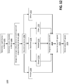
- FIG. 12 illustrates a flowchart 1200 of an example process for creating and utilizing a waveguide network device in a satellite system.
- a determination of input channels and output channels is made.
- the signal paths and design specifications for the housings are first determined before the creation of a waveguide network device.
- block 1204 once the determination has been made, the internal geometry of device to match input and output channels of the device is designed.
- a waveguide network device is then generated or manufactured.
- the waveguide network device can be manufactured by printing 1208, machining 1210, and/or other manufacturing processes 1212.
- the attachment between the housings can be vacuum brazing 1214, welding 1216, or via some other processes 1218 known in the art.
- the waveguide network device when the waveguide network device is manufactured, the device is then configured to be integrated in a satellite system (e.g., spacecraft).
- the waveguide network device when implemented in the satellite device, may receive RF signals from an input port of the one or more waveguide channels in one of at least two housings.
- the waveguide network device is then configured to output the signal in the desired configuration.
- FIG. 13 is an example schematic diagram 1300 of a computing device 1399 that may be used to direct the manufacture of a waveguide network device 1350.
- the computing device 1399 is connected to a printer 1340, which is connected to provide design aspects or design specifications of the device.
- the printer is a three-dimensional (3-D) printer.
- the design specifications are configured to direct the printer 1340 to manufacture the waveguide network device 1350.
- the computing device 1399 may include a processor 1302, a memory device 1304 coupled to processor 1302, one or more wireless transmitters 1306, one or more wireless receivers 1308.
- the computing device 1399 may also include at least one output component 1389 for presenting information to a user 1301 and a printer 1340.
- Output component 1389 may be any component capable of conveying information to user 1301 and printer 1340.
- output component 1389 includes an output adapter, such as a video adapter and/or an audio adapter or the like.
- An output adapter is operatively coupled to processor 1302 and is configured to be operatively coupled to an output device, such as a display device (e.g., a liquid crystal display (LCD), organic light emitting diode (OLED) display, cathode ray tube (CRT), "electronic ink” display, or the like) or an audio output device (e.g., a speaker, headphones, or the like).
- a display device e.g., a liquid crystal display (LCD), organic light emitting diode (OLED) display, cathode ray tube (CRT), "electronic ink” display, or the like
- an audio output device e.g., a speaker, headphones, or the like.
- at least one such display device and/or audio device is included with output component 1389.
- the computing device 1399 may also include at least one input component 1388 for receiving input from user 1301.
- Input component 1388 may include, for example, a keyboard, a pointing device, a mouse, a stylus, a touch sensitive panel (e.g., a touch pad or a touch screen), a gyroscope, an accelerometer, a position detector, an audio input device, or the like.
- a single component, such as a touch screen may function as both an output device of output component 1389 and input component 1388.
- output component 1389 and/or input component 1388 include an adapter for communicating data and/or instructions between the node and a computer connected thereto.
- various examples may include a device 200 for directing waveguide routes.
- the device includes at least two housings 201, 203 configured to: receive, from an input port 520, 516 of one or more waveguide channels 402, 404 in one of the at least two housings 201, 203, a signal; and redirect 1224 the signal to a predetermined output port 518, 512 of one or more waveguide channels 402, 404 in any one of the at least two housings 201, 203, wherein the at least two housings 201, 203 are configured to attach to each other.
- the device may be one wherein the at least two housings 201, 203 are vacuum brazed together to attach and form a single device 200.
- the device 200 may be located inside of a payload cavity of a satellite system at an antenna-payload interface.
- the device 200 may be further configured to be manufactured by a three-dimensional (3-D) printer 1340.
- the device may be one wherein the signal includes a radio frequency (RF) signal.
- RF radio frequency
- the device may be one wherein the number of waveguide channels 402 in a first housing 203 of the at least two housings is less than the number of waveguide channels 404 in a second housing 201 of the at least two housings 201,203.
- the device may be one wherein the at least two housings 201, 203 are configured to be attached using a custom-designed double 90 degree bend 1101.
Landscapes
- Engineering & Computer Science (AREA)
- Manufacturing & Machinery (AREA)
- Chemical & Material Sciences (AREA)
- Materials Engineering (AREA)
- Waveguides (AREA)
- Details Of Aerials (AREA)
- Radio Relay Systems (AREA)
Abstract
Description
- The present disclosure relates generally, but not exclusively, to satellite systems and designing and integrating a waveguide network in a satellite system for simplifying complex waveguide networks, and more particularly to a device configured to enable waveguide routes to be redirected to specific or predetermined output ports.
- Designing and integrating waveguide networks has historically been a challenging mechanical problem. This is primarily due to the fact that current waveguide manufacturing techniques necessitate a high number of individual components and heuristic waveguide routing methods.
- This Summary is provided to introduce a selection of concepts in a simplified form that are further described below in the Detailed Description. This Summary is not intended to identify key features or essential features of the claimed subject matter, nor is it intended to be used to limit the scope of the claimed subject matter.
- The illustrative examples described below provide an improved design to satellite systems by employing a single component or device (e.g. "waveguide network device") that accepts waveguide routes as an input, and then outputs the same routes in any desired configuration (e.g., "detangling" the routes). The waveguide network device may also be referred to as a "waveguide detangler." This device effectively simplifies complex waveguide networks, making them more flexible and the associated engineering more affordable. The waveguide network device can have any number of housings and is capable of inputting or outputting the signals in any of those housings. Moreover, the placement of the waveguide network device at an interface location provides the ability to break up the design of a complex waveguide network. In other words, a large satellite system becomes much more flexible. Any late changes in waveguide routing requirements can be absorbed by the waveguide network device. In other words, a design change to alter the waveguide paths would necessitate that a new waveguide network device be manufactured. Conventionally, a change like this would result in many waveguide routes be re-designed, but the present disclosure could be used to isolate the change to only one part, i.e., the waveguide network device.
- In illustrative examples of the present disclosure, a device and a method are provided for directing waveguide routes in a satellite system. According to one particular implementation, a waveguide network device comprises at least two housings attached together. A first housing may include one or more waveguide channels, each of which includes a first input port and a first output port. Similarly, a second housing may include one or more waveguide channels, each of which includes a second input port and a second output port. The second housing may be configured to receive a signal from the first input port of a waveguide channel in the first housing, and redirect the signal to an output port either of the second housing or of the waveguide channel in the first housing.
- According to another particular implementation, a waveguide network device comprises at least two housings attached together. The waveguide network device may be configured to receive from an input port of one or more waveguide channels in one of the at least two housings, a signal. The waveguide network device may be further configured to redirect the signal to a predetermined output port of one or more waveguide channels in any one of the at least two housings.
- According to yet another particular implementation, a method is disclosed herein. An example of the inventive method comprises determining an output port of one or more waveguide channels in a first or second housing. The method may comprise attaching the first housing to the second housing to form a single device configured to redirect signals to the determined output port of the waveguide channels in the first or second housing.
- The foregoing Summary and the following Detailed Description are better understood when read in conjunction with the appended drawings. In order to illustrate the present disclosure, various aspects of the disclosure are shown. However, the disclosure is not limited to the specific aspects discussed. The following figures are included:
-
FIG. 1 illustrates a known example of a waveguide network and an alternate example of a waveguide network device in a satellite system. -
FIG. 2 illustrates an overview of an example of a waveguide network device with two housings and a brazed layer in between. -
FIG. 3 depicts a perspective view of a waveguide network device. -
FIGS. 4A-4C depict a top view and cross-section views of the waveguide network device ofFIG. 3 . -
FIG. 5 illustrates a detailed cross-section view of the waveguide network device ofFIG. 4C . -
FIGS. 6A-6C depict an alternate top view and alternate cross-section views of the waveguide network device ofFIG. 3 . -
FIG. 7 depicts a detailed alternate cross-section view of the waveguide network device ofFIG. 6C . -
FIGS. 8-9 depict an example of a portion of a payload in a satellite system without a waveguide network device and an alternate example of a portion of a payload in a satellite system with a waveguide network device. -
FIG. 10 illustrates an example of the design methodology to create a waveguide network device. -
FIGS. 11A-11N depict examples of individual RF paths of the waveguide network device depicted inFIG. 3 . -
FIG. 12 is a flow diagram representing the creation and utilization of a waveguide network device in a satellite system. -
FIG. 13 illustrates an example schematic diagram of a system with a computing device configured to manufacture the waveguide network device ofFIG. 3 . - In a satellite system environment, a waveguide is typically used to route signals (e.g., RF signals). This satellite system environment may, for instance, include a multi-beam satellite. Generally, the manufacturing of conventional waveguide is performed by brazing elbows and flanges to extruded pieces of aluminum. The individual pieces of conventional waveguide are then mechanically fastened together to form a waveguide network. While the manufacturing of individual conventional waveguide pieces is inexpensive, the entire waveguide network can get very expensive, inefficient, and inflexible due to the following engineering challenges:
- 1) Complex waveguide networks require a high number of components to ensure the waveguide correctly routes the RF signals while also maintaining structural support and integrity. Designing these networks is heuristic and labor-intensive, and also typically leads to non-optimized routes and line-lengths.
- 2) For waveguide networks with a high waveguide density, it is often difficult to ensure that every mechanical attachment is properly torqued and staked. These mechanical constraints make the integration of complex waveguide networks cumbersome and expensive.
- 3) Once complete, any change to the waveguide network almost certainly has cascading effects, potentially requiring a complete re-design. This makes the larger system inflexible to late changes in requirements.
- 4) Often, waveguide networks become so large that they must be divided between differing subsystem groups, which then route to a common interface location. On a satellite, for example, the antenna group and payload layout group both route waveguide to the antenna-payload interface. Ensuring that all the routes correctly align at this location has been shown to be an iterative and labor-intensive process.
- 5) In order to process large amounts of data, high throughput multi-spot beam payloads are becoming the standard in the commercial satellite industry and these multi-spot beam payloads inherently have very complex waveguide networks.
- Thus, a waveguide network device with at least two housings configured to receive a signal from one of the at least two housings, redirect the signal, and output the signal to a predetermined or specific output port in either the same housing the signal was received from or to an output port in a different housing may be advantageous. That is, the technical solution described herein is an example of a waveguide network device that significantly reduces the number of required mechanical attachments or parts but contains some functionality that redirects or reroutes signal paths is beneficial to any communication system containing a waveguide network.
- Unlike conventional waveguide that is comprised of individual pieces of extruded aluminum, a waveguide network device is comprised of numerous waveguide channels in a single part. Specifically, the waveguide network device may comprise of at least two or more housings brazed together. This enables waveguide routes or signals to compactly "jump" from one waveguide channel to another, and effectively gives the waveguide network device the flexibility for any input port to be routed to any desired output port.
- The various examples used in this disclosure are in the context of the design and development of satellite systems, but it should be understood that the described principles may be applied to other developmental scenarios involving satellite systems in a communication network.
-
FIG. 1 illustrates two types of waveguide network solutions for a satellite system.Waveguide network 105 is known in the art. That is,waveguide network 105 is generally known to those in the art as a portion of a waveguide network with conventional waveguides that are comprised of extruded aluminum. However,waveguide network device 110, as shown inFIG. 1 and as will be described further in detail in the present disclosure, is a simplified version of thewaveguide network 105. Thiswaveguide network device 110 in conjunction with certain engineering design aspects may simplify signal navigation in a satellite system. - An example of a device in accordance with the present disclosure is a
waveguide network device 110 that accepts radio-frequency (RF) signals as an input, and then outputs the same routes in any desired configuration. Thewaveguide network device 110 is comprised of at least two housing portions configured to attach to one another. The individual housings are attached using vacuum brazing. However, as known to those skilled in the art there exists other possible ways to attach housing portions together. -
FIG. 2 shows an example of a 16-channelwaveguide network device 200 with two housing portions configured to be attached together. The number of waveguide channels chosen for thedevice 200 is non-limiting; therefore, any possible number of waveguide channels may be configured. Thus, the number of channel waveguides may, for instance, consist of: 10, 50, 100 or more channels. Moreover and as described in further detail with respect toFIG. 3 , the number of housings fordevice 200 may also be configured with more than just two housing portions attached together. - Here in
FIG. 2 , thedevice 200 is comprised of at least afirst housing 203 and asecond housing 201. Thefirst housing 203 includes one or more waveguide channels. Each of the waveguide channels further includes an input port and an output port. As shown inFIG. 2 , thesecond housing 201 is configured to attach to thefirst housing 203 with abraze sheet 202 in between. In one example, thissecond housing 201 is configured to receive one or more signals from the input ports of thefirst housing 203 and redirect the one or more signals to a specific or predetermined output port of thefirst housing 203 or of thesecond housing 201. Thesecond housing 201 is preconfigured or manufactured with a design directed to simplify a certain type of satellite system (e.g., IntelSat-33, ViaSat-2, or InmarSat F4). Simply put, thesecond housing 201 is configured to receive an input signal and redirect the signal to a desired output port of one of the waveguide channels located in thefirst housing 203 orsecond housing 201. - Similar to the configuration of the
first housing 203, thesecond housing 201 also includes multiple input ports and output ports. In one alternate example, thesecond housing 201 includes less waveguide channels. In other words, thesecond housing 201 has a number of waveguide channels that is less than the number of the waveguide channels of thefirst housing 203. However, it is also possible that thesecond housing 201 includes a number of waveguide channels that is more than the number of waveguide channels of thefirst housing 203. - Specifically, the
device 200 inFIG. 2 shows an exploded view of a waveguide network device, which may represent what the waveguide network device looks like prior to the brazing operation for this particular example. A satellite system with awaveguide network device 200 incorporated therein simplifies the overall waveguide network. Furthermore, thewaveguide network device 200 can be replaced if a user or operator of the satellite system decides to alter some of the signal paths. The placement of thewaveguide network device 200 at an interface location provides an ability to break up the design of a complex waveguide network. In other words, a large satellite system becomes much more flexible. Any late changes in waveguide routing requirements are completely absorbed by thewaveguide network device 200. -
FIG. 3 illustrates a perspective view of awaveguide network device 300.FIG. 3 depicts thewaveguide network device 300 with only two housings attached together; however as analyzed above and described herein, the number of housings may vary (e.g. more than two housings). Thus, thiswaveguide network device 300 may comprise of a single unit or component when at least two housing portions are attached together. That is, in alternate examples, thewaveguide network device 300 includes three housing portions or four housing portions attached together. In other words, the single component can include any number of housings attached together and accept an arbitrary number of waveguide routes and output those routes in any configuration so long as space permits. -
FIGS. 4A-4C depict a top view and multiple cross-sectional views of the waveguide network device. As shown inFIG. 4A , a top view of the waveguide network device is illustrated. InFIG. 4B , a cross-sectional view of the waveguide network device is illustrated. InFIG. 4C , afirst housing 403 of the waveguide network device includes one ormore waveguide channels 402. Each of the one or more waveguide channels in the first housing also includes an input and an output port. Furthermore,FIG. 4C shows a more detailed illustration of asecond housing 401 that is layered or attached to thefirst housing 403. Thesecond housing 401 includes one ormore waveguide channels 404. Similar to the configuration of thefirst housing 403, thesecond housing 401 also includes multiple input and output ports. A more detailed illustration of the input and output ports for each of the housings is described below inFIG. 5 . -
FIG. 5 depicts a more detailed cross-sectional view of thewaveguide network device 300 described inFIG. 3 and4C .FIG. 5 illustrates a view where a signal may start in the first housing, jump to the second housing, and then output in one of the output ports of the first housing. As shown inFIG. 5 , a first housing includes one or more waveguide channels. Each of the one or more waveguide channels in the first housing also includes an input and an output port. For instance, the waveguide network device inFIG. 5 illustrates afirst input port 520 and afirst output port 518 of the first housing. Asecond input port 514 and asecond output port 510 of the first housing is also illustrated. Furthermore,FIG. 5 shows a second housing that is layered or attached to the first housing. The second housing includes one or more waveguide channels. Similar to the configuration of the first housing, the second housing also includes multiple input and output ports. That is,FIG. 5 illustrates aninput port 516 and anoutput port 512 of the second housing. -
FIGS. 6A-6B illustrate top views of the waveguide network device.FIGS. 6C and7 illustrate a more detailed cross-section view of the waveguide network device. More specifically, the waveguide network device inFIG. 7 provides a view where a signal may start in the first housing and be re-directed to an output port of the second housing. The waveguide network device inFIG. 7 is similar to that described above with respect toFIG. 5 , but differs in that the cross-section is now of an RF path that outputs from the second housing as opposed to outputting from the first housing. Each of the one or more waveguide channels in the first housing also includes an input and an output port. For instance, the waveguide network device inFIG. 7 illustrates afirst input port 720 and afirst output port 718 of the first housing. Furthermore,FIG. 7 shows a second housing that is layered or attached to the first housing. The second housing includes one or more waveguide channels. Similar to the configuration of the first housing, the second housing also includes multiple input and output ports. That is,FIG. 7 illustrates aninput port 716 and anoutput port 712 of the second housing. -
FIG. 8 depicts an example of a portion of a payload in a satellite system without awaveguide network device 801 andFIG. 9 depicts an alternate example of the portion of the payload in the satellite system with awaveguide network device 901. As shown inFIG. 9 , the waveguide network is simplified with awaveguide network device 905 contained in the satellite system. Moreover, the amount of parts necessary and mechanical attachments required when a satellite system incorporates or integrates a waveguide network device is clearly less than a satellite system without a waveguide network device. Put another way, the costs and expenses associated with the design and integration can be lowered when using a waveguide network device inside of a satellite system. -
FIG. 10 illustrates an example of thedesign methodology 1000 to create a waveguide network device. As shown inFIG. 10 , in one example of the design methodology, the route paths for each individual signal are predetermined and designed before the integration of the waveguide network device into the satellite system. The process includes designing or configuring the routes or route paths for each individual waveguide channel. In other words, the design or configuration of the one or more waveguide channels in a first housing and the one or more waveguide channels in a second housing are predetermined before manufacturing the waveguide network device. Once the design is determined, in one illustrative example and as further described below with respect toFIG. 13 , the design may be transferred to a separate computing device. The computing device may then utilize the design to direct a printer, a three-dimensional (3-D) printer, or some sort of manufacturing device to manufacture the waveguide network device. -
FIGS. 11A-11N depict the individual RF paths of the waveguide network device depicted inFIG. 3 .FIGS. 11A-11N depict the waveguide network device with only two housings; however, as analyzed above, the number of housings may vary (e.g. more than two housings). Here inFIG. 11A , a second housing is attached to a first housing in a manner such that the waveguide channels of the first housing and a second housing are orthogonal. This configuration may be created by a custom-designed ((e.g., using a High-Frequency Structure Simulator (HFSS) software)) double-90degree bend 1101 in the RF path. This custom-designedbend 1101 enables the waveguide routes to be as compact as possible (e.g., shared walls are maintained) with minimal loss. Moreover, by having this custom-designed bend (e.g., double- 90 degree bend) 1101, all the RF paths are orientated either in the vertical (e.g., top or down) or horizontal (e.g., left or right) direction. As an example, the bent portions in the second housing are configured such that signals that navigate through the waveguide channels will not bounce backwards or in a different direction than the direction the path is designed for. In other words, the second housing may be preconfigured in a certain shape, size, and/or angle so that signals do not deviate from their paths. The remainingFIGS. 11B-11N illustrate the other individual RF paths being routed through the waveguide network device. -
FIG. 12 illustrates aflowchart 1200 of an example process for creating and utilizing a waveguide network device in a satellite system. Referring to blocks 1201-1202, a determination of input channels and output channels is made. The signal paths and design specifications for the housings are first determined before the creation of a waveguide network device. Now referring to block 1204, once the determination has been made, the internal geometry of device to match input and output channels of the device is designed. - In block, 1206, a waveguide network device is then generated or manufactured. The waveguide network device can be manufactured by printing 1208, machining 1210, and/or other manufacturing processes 1212. For conventionally machined housings, the attachment between the housings can be
vacuum brazing 1214, welding 1216, or via someother processes 1218 known in the art. - Referring to block 1220, once the waveguide network device is manufactured, the device is then configured to be integrated in a satellite system (e.g., spacecraft). In
block 1222, the waveguide network device, when implemented in the satellite device, may receive RF signals from an input port of the one or more waveguide channels in one of at least two housings. - Referring to block 1224, the waveguide network device is then configured to output the signal in the desired configuration.
-
FIG. 13 is an example schematic diagram 1300 of acomputing device 1399 that may be used to direct the manufacture of awaveguide network device 1350. As described above, thecomputing device 1399 is connected to aprinter 1340, which is connected to provide design aspects or design specifications of the device. In one example, the printer is a three-dimensional (3-D) printer. The design specifications are configured to direct theprinter 1340 to manufacture thewaveguide network device 1350. In one example, thecomputing device 1399 may include aprocessor 1302, amemory device 1304 coupled toprocessor 1302, one ormore wireless transmitters 1306, one ormore wireless receivers 1308. - The
computing device 1399 may also include at least oneoutput component 1389 for presenting information to a user 1301 and aprinter 1340.Output component 1389 may be any component capable of conveying information to user 1301 andprinter 1340. In some implementations,output component 1389 includes an output adapter, such as a video adapter and/or an audio adapter or the like. An output adapter is operatively coupled toprocessor 1302 and is configured to be operatively coupled to an output device, such as a display device (e.g., a liquid crystal display (LCD), organic light emitting diode (OLED) display, cathode ray tube (CRT), "electronic ink" display, or the like) or an audio output device (e.g., a speaker, headphones, or the like). In some implementations, at least one such display device and/or audio device is included withoutput component 1389. - The
computing device 1399 may also include at least oneinput component 1388 for receiving input from user 1301.Input component 1388 may include, for example, a keyboard, a pointing device, a mouse, a stylus, a touch sensitive panel (e.g., a touch pad or a touch screen), a gyroscope, an accelerometer, a position detector, an audio input device, or the like. A single component, such as a touch screen, may function as both an output device ofoutput component 1389 andinput component 1388. In some implementations,output component 1389 and/orinput component 1388 include an adapter for communicating data and/or instructions between the node and a computer connected thereto. - Conditional language used herein, such as, among others, "can," "could," "might," "may," "e.g.," and the like, unless specifically stated otherwise, or otherwise understood within the context as used, is generally intended to convey that certain examples include, while other examples do not include, certain features, elements, and/or steps. Thus, such conditional language is not generally intended to imply that features, elements and/or steps are in any way required for one or more examples or that one or more examples necessarily include logic for deciding, with or without author input or prompting, whether these features, elements and/or steps are included or are to be performed in any particular example. The terms "comprising," "including," "having," and the like are synonymous and are used inclusively, in an open-ended fashion, and do not exclude additional elements, features, acts, operations, and so forth. Also, the term "or" is used in its inclusive sense (and not in its exclusive sense) so that when used, for example, to connect a list of elements, the term "or" means one, some, or all of the elements in the list. As used in the description of the disclosure and the appended claims, the singular forms "a", "an" and "the" are intended to include the plural forms as well, unless the context clearly indicates otherwise. It will be further understood that the terms "comprises" or "comprising," when used in this specification, specify the presence of stated features, integers, steps, operations, elements, and/or components, but do not preclude the presence or addition of one or more other features, integers, steps, operations, elements, components, and/or groups thereof. Furthermore, the terms "assets" and "computing devices," when used in this specification, may be used interchangeably.
- In general, the various features and processes described above may be used independently of one another, or may be combined in different ways. All possible combinations and subcombinations are intended to fall within the scope of this disclosure. In addition, certain method or process blocks may be omitted in some implementations. The methods and processes described herein are also not limited to any particular sequence, and the blocks or states relating thereto can be performed in other sequences that are appropriate. For example, described blocks or states may be performed in an order other than that specifically disclosed, or multiple blocks or states may be combined in a single block or state. The example blocks or states may be performed in serial, in parallel, or in some other manner. Blocks or states may be added to or removed from the disclosed examples. The example systems and components described herein may be configured differently than described. For example, elements may be added to, removed from, or rearranged compared to the disclosed example examples.
- For example, various examples may include a
device 200 for directing waveguide routes. The device includes at least twohousings input port more waveguide channels housings predetermined output port more waveguide channels housings housings - Advantageously, the device may be one wherein the at least two
housings single device 200. - Preferably, the
device 200 may be located inside of a payload cavity of a satellite system at an antenna-payload interface. - Advantageously, the
device 200 may be further configured to be manufactured by a three-dimensional (3-D)printer 1340. - Advantageously, the device may be one wherein the signal includes a radio frequency (RF) signal.
- Advantageously, the device may be one wherein the number of
waveguide channels 402 in afirst housing 203 of the at least two housings is less than the number ofwaveguide channels 404 in asecond housing 201 of the at least two housings 201,203. - Advantageously, the device may be one wherein the at least two
housings degree bend 1101. - It will be understood by those skilled in the art that various changes may be made and equivalents may be substituted for elements thereof without departing from the scope of the teachings herein. In addition, many modifications may be made to adapt the teachings herein to a particular situation without departing from the scope thereof. Therefore, it is intended that the claims not be limited to the particular implementations disclosed herein.
Claims (14)
- A device (200) for directing waveguide routes, the device comprising:at least two housings (201, 203) attached together to form the device further comprising:a first housing (203) including one or more waveguide channels (402), wherein each of the one or more waveguide channels (402) in the first housing (203) includes a first input port (520) and a first output port (518); anda second housing (201) configured to attach to the first housing (203), wherein the second housing (201) includes one or more waveguide channels (404), wherein each of the one or more waveguide channels (404) in the second housing (201) includes a second input port (516) and a second output port (512),wherein the second housing (201) is configured to receive a signal from the first input port (520) of the one or more waveguide channels (402) in the first housing (203); andwherein the second housing (201) is configured to redirect the signal to a predetermined output port (518, 512) of the one or more waveguide channels (402,404) in the first (203) or second (201) housing.
- The device of claim 1, wherein the first housing (203) and the second housing (201) are vacuum brazed together to attach and form the device (200).
- The device of claim 1 or 2, wherein the device (200) is located inside of a payload cavity of a satellite system at an antenna-payload interface.
- The device of any of claims 1-3, wherein the signal includes a radio frequency (RF) signal.
- The device of any preceding claim, wherein the device (200) is configured to be manufactured by a printer (1340).
- The device of claim 5, wherein the printer (1340) is a three-dimensional (3-D) printer (1340).
- The device of any preceding claim, wherein the number of waveguide channels (404) in the second housing is less than the number of waveguide channels (402) in the first housing.
- The device of any preceding claim, wherein the second housing (201) and the first housing (203) are attached using a custom-designed double 90 degree bend (1101).
- A method comprising:determining an output port (518) of one or more waveguide channels (402) in a first housing (203) of a plurality of housings or a second housing (201) of the plurality of housings for a signal; andin response to the determination, attaching the first housing (203) to the second housing (201) to form a single device (200), wherein the first housing (203) includes one or more waveguide channels (402), wherein each of the one or more waveguide channels (402) in the first housing (203) includes a first input port (520) and a first output port (518), wherein the second housing (201) includes one or more waveguide channels (404), wherein each of the one or more waveguide channels (404) in the second housing (201) includes a second input port (516) and a second output port (512),wherein the single device (200) is configured to redirect the signal to the determined output port (518, 512) of the one or more waveguide channels (402, 404) in the first (203) or second housing (201).
- The method of claim 9, wherein attaching the first housing (203) and the second housing (201) includes vacuum brazing together the first housing (203) and the second housing (201) to form the single device (200).
- The method of claim 9 or 10, wherein the device (200) is located inside of a payload cavity of a satellite system at an antenna-payload interface.
- The method of any of claims 9-11, wherein the number of waveguide channels (404) in the second housing (201) is less than the number of waveguide channels (402) in the first housing (203).
- The method of any of claims 9-12, wherein the second housing and the first housing are attached using a custom-designed double 90 degree bend (1101).
- A satellite system comprising the device of any one of claims 1 to 8.
Applications Claiming Priority (1)
| Application Number | Priority Date | Filing Date | Title |
|---|---|---|---|
| US15/285,171 US10403956B2 (en) | 2016-10-04 | 2016-10-04 | Simplification of complex waveguide networks |
Publications (2)
| Publication Number | Publication Date |
|---|---|
| EP3306738A1 true EP3306738A1 (en) | 2018-04-11 |
| EP3306738B1 EP3306738B1 (en) | 2021-03-03 |
Family
ID=60001645
Family Applications (1)
| Application Number | Title | Priority Date | Filing Date |
|---|---|---|---|
| EP17190300.8A Active EP3306738B1 (en) | 2016-10-04 | 2017-09-11 | Simplification of complex waveguide networks |
Country Status (5)
| Country | Link |
|---|---|
| US (2) | US10403956B2 (en) |
| EP (1) | EP3306738B1 (en) |
| JP (1) | JP7023631B2 (en) |
| CN (1) | CN107895831B (en) |
| RU (1) | RU2755173C2 (en) |
Families Citing this family (3)
| Publication number | Priority date | Publication date | Assignee | Title |
|---|---|---|---|---|
| US11313243B2 (en) | 2018-07-12 | 2022-04-26 | Rolls-Royce North American Technologies, Inc. | Non-continuous abradable coatings |
| EP3822004A1 (en) | 2019-11-14 | 2021-05-19 | Rolls-Royce Corporation | Fused filament fabrication of abradable coatings |
| CN112490635B (en) * | 2020-11-05 | 2023-03-14 | 陕西飞机工业(集团)有限公司 | Matrix waveguide and airplane integrated integration method and system |
Citations (3)
| Publication number | Priority date | Publication date | Assignee | Title |
|---|---|---|---|---|
| US6011453A (en) * | 1996-05-23 | 2000-01-04 | Telefonaktiebolaget Lm Ericsson | Compact wave guide arrangement and a method for producing it |
| JP2010199992A (en) * | 2009-02-25 | 2010-09-09 | Toshiba Corp | Waveguide device |
| US20100321136A1 (en) * | 2007-12-20 | 2010-12-23 | Per Ligander | Waveguide transition arragement |
Family Cites Families (15)
| Publication number | Priority date | Publication date | Assignee | Title |
|---|---|---|---|---|
| JPH077882B2 (en) * | 1986-03-04 | 1995-01-30 | 日本電信電話株式会社 | Piping method for waveguide for polarization splitter |
| US4812788A (en) * | 1987-11-02 | 1989-03-14 | Hughes Aircraft Company | Waveguide matrix including in-plane crossover |
| IL91529A0 (en) * | 1988-10-28 | 1990-04-29 | Motorola Inc | Satellite cellular telephone and data communication system |
| US6037909A (en) * | 1997-03-21 | 2000-03-14 | Space Systems/Loral, Inc. | Deployed payload for a communications spacecraft |
| JP2002135016A (en) * | 2000-10-20 | 2002-05-10 | Toshiba Corp | Waveguide and its manufacturing method |
| US8872333B2 (en) | 2008-02-14 | 2014-10-28 | Viasat, Inc. | System and method for integrated waveguide packaging |
| EP2345099B1 (en) * | 2008-10-27 | 2015-02-18 | Panasonic Avionics Corporation | A waveguide antenna front end |
| US7821355B2 (en) | 2008-10-27 | 2010-10-26 | Starling Advanced Communications Ltd. | Waveguide antenna front end |
| JP5309209B2 (en) * | 2009-03-31 | 2013-10-09 | 京セラ株式会社 | Waveguide structure, and high-frequency module and radar apparatus including waveguide structure |
| US8244287B2 (en) * | 2009-10-29 | 2012-08-14 | Z-Communications, Inc. | Radio and antenna system and dual-mode microwave coupler |
| US8988300B2 (en) * | 2011-12-06 | 2015-03-24 | Viasat, Inc. | Dual-circular polarized antenna system |
| US9306254B1 (en) * | 2013-03-15 | 2016-04-05 | Nuvotronics, Inc. | Substrate-free mechanical interconnection of electronic sub-systems using a spring configuration |
| EP3193404A4 (en) * | 2014-09-09 | 2018-04-18 | Mitsubishi Electric Corporation | Waveguide device |
| US9923256B2 (en) * | 2015-02-27 | 2018-03-20 | Viasat, Inc. | Ridge loaded waveguide combiner/divider |
| CN105140610B (en) * | 2015-09-08 | 2018-03-02 | 安徽四创电子股份有限公司 | A kind of equivalent 180 ° of ridge waveguides for ridge waveguide slot array are curved |
-
2016
- 2016-10-04 US US15/285,171 patent/US10403956B2/en active Active
-
2017
- 2017-07-12 RU RU2017124910A patent/RU2755173C2/en active
- 2017-07-14 JP JP2017137808A patent/JP7023631B2/en active Active
- 2017-09-11 EP EP17190300.8A patent/EP3306738B1/en active Active
- 2017-09-11 CN CN201710811358.6A patent/CN107895831B/en active Active
-
2019
- 2019-09-03 US US16/559,223 patent/US11114737B2/en active Active
Patent Citations (3)
| Publication number | Priority date | Publication date | Assignee | Title |
|---|---|---|---|---|
| US6011453A (en) * | 1996-05-23 | 2000-01-04 | Telefonaktiebolaget Lm Ericsson | Compact wave guide arrangement and a method for producing it |
| US20100321136A1 (en) * | 2007-12-20 | 2010-12-23 | Per Ligander | Waveguide transition arragement |
| JP2010199992A (en) * | 2009-02-25 | 2010-09-09 | Toshiba Corp | Waveguide device |
Non-Patent Citations (3)
| Title |
|---|
| HENKE DOUG ET AL: "Design of a 70-116 GHz W-band turnstile", 2014 44TH EUROPEAN MICROWAVE CONFERENCE, EUROPEAN MICROWAVE ASSOCIATION, 6 October 2014 (2014-10-06), pages 456 - 459, XP032706394, DOI: 10.1109/EUMC.2014.6986469 * |
| HUANG GUAN-LONG ET AL: "A compact wideband 16-way power combiner implemented via 3-D metal printing", 2016 IEEE 5TH ASIA-PACIFIC CONFERENCE ON ANTENNAS AND PROPAGATION (APCAP), IEEE, 26 July 2016 (2016-07-26), pages 51 - 52, XP033057791, DOI: 10.1109/APCAP.2016.7843094 * |
| MCKERRICHER G ET AL: "Lightweight 3D printed microwave waveguides and waveguide slot antenna", 2015 IEEE INTERNATIONAL SYMPOSIUM ON ANTENNAS AND PROPAGATION & USNC/URSI NATIONAL RADIO SCIENCE MEETING, IEEE, 19 July 2015 (2015-07-19), pages 1322 - 1323, XP032796732, DOI: 10.1109/APS.2015.7305050 * |
Also Published As
| Publication number | Publication date |
|---|---|
| JP2018067905A (en) | 2018-04-26 |
| CN107895831A (en) | 2018-04-10 |
| RU2017124910A3 (en) | 2021-03-04 |
| EP3306738B1 (en) | 2021-03-03 |
| CN107895831B (en) | 2022-06-03 |
| US20180097271A1 (en) | 2018-04-05 |
| RU2017124910A (en) | 2019-01-14 |
| JP7023631B2 (en) | 2022-02-22 |
| US10403956B2 (en) | 2019-09-03 |
| US11114737B2 (en) | 2021-09-07 |
| RU2755173C2 (en) | 2021-09-13 |
| US20200076044A1 (en) | 2020-03-05 |
Similar Documents
| Publication | Publication Date | Title |
|---|---|---|
| US11114737B2 (en) | Simplification of complex waveguide networks | |
| US10417004B2 (en) | Pipelined cascaded digital signal processing structures and methods | |
| US9547611B2 (en) | Computer system with groups of processor boards | |
| US20170215178A1 (en) | Methods and procedures for dynamic channel assignment and change in unmanned aircraft system (uas) control and non-payload communication | |
| US10425358B2 (en) | Network switch architecture supporting multiple simultaneous collective operations | |
| CN104052540A (en) | Aircraft Communications Switching System | |
| EP3214773A1 (en) | Antenna array coupling and calibrating network device and calibrating method, and storage medium | |
| EP3098899A1 (en) | Partial dielectric loaded septum polarizer | |
| CN111953513B (en) | Constellation topology configuration characterization method and system for Walker constellation and application | |
| EP3100368B1 (en) | Wirelessly connecting an aircraft at an airport | |
| CN111382115B (en) | Path creating method and device for network on chip and electronic equipment | |
| CN108062382A (en) | Method, apparatus, equipment and the storage medium of information exchange | |
| CN105554702A (en) | Cross network positioning system and method, positioning server and mobile terminal | |
| WO2016078445A1 (en) | Method and device for upgrading multi-mode base station and network management system | |
| KR102014122B1 (en) | Input device detection method and detection device | |
| US20200133894A1 (en) | Tray for avionics bay comprising a recording device, associated avionics bay and aircraft | |
| US20190266108A1 (en) | Method for managing routing of transactions between source devices and at least one target device and corresponding system on chip | |
| US20120185216A1 (en) | Minimizing the Maximum Required Link Capacity for Three-Dimensional Interconnect Routing | |
| US11343936B2 (en) | Rack switch coupling system | |
| CN112713956B (en) | Frequency selection method, device, equipment and storage medium of synchronous Ethernet | |
| KR101959393B1 (en) | A method and apparatus for simultaneously supporting mf-tdma and fdma in dvb-rcs system | |
| US20210232518A1 (en) | Rack switch coupling system | |
| US10747934B2 (en) | Managing feedthrough wiring for integrated circuits | |
| US20030135291A1 (en) | Customized ports in a crossbar and method for transmitting data between customized ports and system agents | |
| US20210232523A1 (en) | Rack switch coupling system |
Legal Events
| Date | Code | Title | Description |
|---|---|---|---|
| PUAI | Public reference made under article 153(3) epc to a published international application that has entered the european phase |
Free format text: ORIGINAL CODE: 0009012 |
|
| STAA | Information on the status of an ep patent application or granted ep patent |
Free format text: STATUS: REQUEST FOR EXAMINATION WAS MADE |
|
| 17P | Request for examination filed |
Effective date: 20170911 |
|
| AK | Designated contracting states |
Kind code of ref document: A1 Designated state(s): AL AT BE BG CH CY CZ DE DK EE ES FI FR GB GR HR HU IE IS IT LI LT LU LV MC MK MT NL NO PL PT RO RS SE SI SK SM TR |
|
| AX | Request for extension of the european patent |
Extension state: BA ME |
|
| STAA | Information on the status of an ep patent application or granted ep patent |
Free format text: STATUS: EXAMINATION IS IN PROGRESS |
|
| 17Q | First examination report despatched |
Effective date: 20190218 |
|
| REG | Reference to a national code |
Ref country code: DE Ref legal event code: R079 Ref document number: 602017033688 Country of ref document: DE Free format text: PREVIOUS MAIN CLASS: H01P0001020000 Ipc: H01P0005120000 |
|
| RIC1 | Information provided on ipc code assigned before grant |
Ipc: H01P 5/12 20060101AFI20200724BHEP Ipc: H01P 5/02 20060101ALI20200724BHEP Ipc: H01P 1/02 20060101ALI20200724BHEP Ipc: B33Y 80/00 20150101ALI20200724BHEP |
|
| GRAP | Despatch of communication of intention to grant a patent |
Free format text: ORIGINAL CODE: EPIDOSNIGR1 |
|
| STAA | Information on the status of an ep patent application or granted ep patent |
Free format text: STATUS: GRANT OF PATENT IS INTENDED |
|
| INTG | Intention to grant announced |
Effective date: 20200922 |
|
| RIN1 | Information on inventor provided before grant (corrected) |
Inventor name: GALE, JEFFREY C. Inventor name: HUTCHINSON, BRYCE Inventor name: ALVAREZ, DANIEL A. Inventor name: MICHALS, LUCAS GORDON |
|
| GRAS | Grant fee paid |
Free format text: ORIGINAL CODE: EPIDOSNIGR3 |
|
| STAA | Information on the status of an ep patent application or granted ep patent |
Free format text: STATUS: GRANT OF PATENT IS INTENDED |
|
| GRAA | (expected) grant |
Free format text: ORIGINAL CODE: 0009210 |
|
| STAA | Information on the status of an ep patent application or granted ep patent |
Free format text: STATUS: THE PATENT HAS BEEN GRANTED |
|
| AK | Designated contracting states |
Kind code of ref document: B1 Designated state(s): AL AT BE BG CH CY CZ DE DK EE ES FI FR GB GR HR HU IE IS IT LI LT LU LV MC MK MT NL NO PL PT RO RS SE SI SK SM TR |
|
| REG | Reference to a national code |
Ref country code: GB Ref legal event code: FG4D |
|
| REG | Reference to a national code |
Ref country code: AT Ref legal event code: REF Ref document number: 1368220 Country of ref document: AT Kind code of ref document: T Effective date: 20210315 Ref country code: CH Ref legal event code: EP |
|
| REG | Reference to a national code |
Ref country code: DE Ref legal event code: R096 Ref document number: 602017033688 Country of ref document: DE |
|
| REG | Reference to a national code |
Ref country code: IE Ref legal event code: FG4D |
|
| REG | Reference to a national code |
Ref country code: LT Ref legal event code: MG9D |
|
| PG25 | Lapsed in a contracting state [announced via postgrant information from national office to epo] |
Ref country code: NO Free format text: LAPSE BECAUSE OF FAILURE TO SUBMIT A TRANSLATION OF THE DESCRIPTION OR TO PAY THE FEE WITHIN THE PRESCRIBED TIME-LIMIT Effective date: 20210603 Ref country code: FI Free format text: LAPSE BECAUSE OF FAILURE TO SUBMIT A TRANSLATION OF THE DESCRIPTION OR TO PAY THE FEE WITHIN THE PRESCRIBED TIME-LIMIT Effective date: 20210303 Ref country code: HR Free format text: LAPSE BECAUSE OF FAILURE TO SUBMIT A TRANSLATION OF THE DESCRIPTION OR TO PAY THE FEE WITHIN THE PRESCRIBED TIME-LIMIT Effective date: 20210303 Ref country code: GR Free format text: LAPSE BECAUSE OF FAILURE TO SUBMIT A TRANSLATION OF THE DESCRIPTION OR TO PAY THE FEE WITHIN THE PRESCRIBED TIME-LIMIT Effective date: 20210604 Ref country code: BG Free format text: LAPSE BECAUSE OF FAILURE TO SUBMIT A TRANSLATION OF THE DESCRIPTION OR TO PAY THE FEE WITHIN THE PRESCRIBED TIME-LIMIT Effective date: 20210603 Ref country code: LT Free format text: LAPSE BECAUSE OF FAILURE TO SUBMIT A TRANSLATION OF THE DESCRIPTION OR TO PAY THE FEE WITHIN THE PRESCRIBED TIME-LIMIT Effective date: 20210303 |
|
| REG | Reference to a national code |
Ref country code: NL Ref legal event code: MP Effective date: 20210303 |
|
| REG | Reference to a national code |
Ref country code: AT Ref legal event code: MK05 Ref document number: 1368220 Country of ref document: AT Kind code of ref document: T Effective date: 20210303 |
|
| PG25 | Lapsed in a contracting state [announced via postgrant information from national office to epo] |
Ref country code: SE Free format text: LAPSE BECAUSE OF FAILURE TO SUBMIT A TRANSLATION OF THE DESCRIPTION OR TO PAY THE FEE WITHIN THE PRESCRIBED TIME-LIMIT Effective date: 20210303 Ref country code: LV Free format text: LAPSE BECAUSE OF FAILURE TO SUBMIT A TRANSLATION OF THE DESCRIPTION OR TO PAY THE FEE WITHIN THE PRESCRIBED TIME-LIMIT Effective date: 20210303 Ref country code: RS Free format text: LAPSE BECAUSE OF FAILURE TO SUBMIT A TRANSLATION OF THE DESCRIPTION OR TO PAY THE FEE WITHIN THE PRESCRIBED TIME-LIMIT Effective date: 20210303 Ref country code: PL Free format text: LAPSE BECAUSE OF FAILURE TO SUBMIT A TRANSLATION OF THE DESCRIPTION OR TO PAY THE FEE WITHIN THE PRESCRIBED TIME-LIMIT Effective date: 20210303 |
|
| PG25 | Lapsed in a contracting state [announced via postgrant information from national office to epo] |
Ref country code: NL Free format text: LAPSE BECAUSE OF FAILURE TO SUBMIT A TRANSLATION OF THE DESCRIPTION OR TO PAY THE FEE WITHIN THE PRESCRIBED TIME-LIMIT Effective date: 20210303 |
|
| PG25 | Lapsed in a contracting state [announced via postgrant information from national office to epo] |
Ref country code: SM Free format text: LAPSE BECAUSE OF FAILURE TO SUBMIT A TRANSLATION OF THE DESCRIPTION OR TO PAY THE FEE WITHIN THE PRESCRIBED TIME-LIMIT Effective date: 20210303 Ref country code: AT Free format text: LAPSE BECAUSE OF FAILURE TO SUBMIT A TRANSLATION OF THE DESCRIPTION OR TO PAY THE FEE WITHIN THE PRESCRIBED TIME-LIMIT Effective date: 20210303 Ref country code: EE Free format text: LAPSE BECAUSE OF FAILURE TO SUBMIT A TRANSLATION OF THE DESCRIPTION OR TO PAY THE FEE WITHIN THE PRESCRIBED TIME-LIMIT Effective date: 20210303 Ref country code: CZ Free format text: LAPSE BECAUSE OF FAILURE TO SUBMIT A TRANSLATION OF THE DESCRIPTION OR TO PAY THE FEE WITHIN THE PRESCRIBED TIME-LIMIT Effective date: 20210303 |
|
| PG25 | Lapsed in a contracting state [announced via postgrant information from national office to epo] |
Ref country code: SK Free format text: LAPSE BECAUSE OF FAILURE TO SUBMIT A TRANSLATION OF THE DESCRIPTION OR TO PAY THE FEE WITHIN THE PRESCRIBED TIME-LIMIT Effective date: 20210303 Ref country code: RO Free format text: LAPSE BECAUSE OF FAILURE TO SUBMIT A TRANSLATION OF THE DESCRIPTION OR TO PAY THE FEE WITHIN THE PRESCRIBED TIME-LIMIT Effective date: 20210303 Ref country code: PT Free format text: LAPSE BECAUSE OF FAILURE TO SUBMIT A TRANSLATION OF THE DESCRIPTION OR TO PAY THE FEE WITHIN THE PRESCRIBED TIME-LIMIT Effective date: 20210705 Ref country code: IS Free format text: LAPSE BECAUSE OF FAILURE TO SUBMIT A TRANSLATION OF THE DESCRIPTION OR TO PAY THE FEE WITHIN THE PRESCRIBED TIME-LIMIT Effective date: 20210703 |
|
| REG | Reference to a national code |
Ref country code: DE Ref legal event code: R097 Ref document number: 602017033688 Country of ref document: DE |
|
| PLBE | No opposition filed within time limit |
Free format text: ORIGINAL CODE: 0009261 |
|
| STAA | Information on the status of an ep patent application or granted ep patent |
Free format text: STATUS: NO OPPOSITION FILED WITHIN TIME LIMIT |
|
| PG25 | Lapsed in a contracting state [announced via postgrant information from national office to epo] |
Ref country code: AL Free format text: LAPSE BECAUSE OF FAILURE TO SUBMIT A TRANSLATION OF THE DESCRIPTION OR TO PAY THE FEE WITHIN THE PRESCRIBED TIME-LIMIT Effective date: 20210303 Ref country code: DK Free format text: LAPSE BECAUSE OF FAILURE TO SUBMIT A TRANSLATION OF THE DESCRIPTION OR TO PAY THE FEE WITHIN THE PRESCRIBED TIME-LIMIT Effective date: 20210303 Ref country code: ES Free format text: LAPSE BECAUSE OF FAILURE TO SUBMIT A TRANSLATION OF THE DESCRIPTION OR TO PAY THE FEE WITHIN THE PRESCRIBED TIME-LIMIT Effective date: 20210303 |
|
| 26N | No opposition filed |
Effective date: 20211206 |
|
| PG25 | Lapsed in a contracting state [announced via postgrant information from national office to epo] |
Ref country code: SI Free format text: LAPSE BECAUSE OF FAILURE TO SUBMIT A TRANSLATION OF THE DESCRIPTION OR TO PAY THE FEE WITHIN THE PRESCRIBED TIME-LIMIT Effective date: 20210303 |
|
| PG25 | Lapsed in a contracting state [announced via postgrant information from national office to epo] |
Ref country code: IT Free format text: LAPSE BECAUSE OF FAILURE TO SUBMIT A TRANSLATION OF THE DESCRIPTION OR TO PAY THE FEE WITHIN THE PRESCRIBED TIME-LIMIT Effective date: 20210303 |
|
| REG | Reference to a national code |
Ref country code: CH Ref legal event code: PL |
|
| REG | Reference to a national code |
Ref country code: BE Ref legal event code: MM Effective date: 20210930 |
|
| PG25 | Lapsed in a contracting state [announced via postgrant information from national office to epo] |
Ref country code: IS Free format text: LAPSE BECAUSE OF FAILURE TO SUBMIT A TRANSLATION OF THE DESCRIPTION OR TO PAY THE FEE WITHIN THE PRESCRIBED TIME-LIMIT Effective date: 20210703 Ref country code: MC Free format text: LAPSE BECAUSE OF FAILURE TO SUBMIT A TRANSLATION OF THE DESCRIPTION OR TO PAY THE FEE WITHIN THE PRESCRIBED TIME-LIMIT Effective date: 20210303 |
|
| PG25 | Lapsed in a contracting state [announced via postgrant information from national office to epo] |
Ref country code: LU Free format text: LAPSE BECAUSE OF NON-PAYMENT OF DUE FEES Effective date: 20210911 Ref country code: IE Free format text: LAPSE BECAUSE OF NON-PAYMENT OF DUE FEES Effective date: 20210911 Ref country code: BE Free format text: LAPSE BECAUSE OF NON-PAYMENT OF DUE FEES Effective date: 20210930 |
|
| PG25 | Lapsed in a contracting state [announced via postgrant information from national office to epo] |
Ref country code: LI Free format text: LAPSE BECAUSE OF NON-PAYMENT OF DUE FEES Effective date: 20210930 Ref country code: CH Free format text: LAPSE BECAUSE OF NON-PAYMENT OF DUE FEES Effective date: 20210930 |
|
| PG25 | Lapsed in a contracting state [announced via postgrant information from national office to epo] |
Ref country code: HU Free format text: LAPSE BECAUSE OF FAILURE TO SUBMIT A TRANSLATION OF THE DESCRIPTION OR TO PAY THE FEE WITHIN THE PRESCRIBED TIME-LIMIT; INVALID AB INITIO Effective date: 20170911 |
|
| P01 | Opt-out of the competence of the unified patent court (upc) registered |
Effective date: 20230516 |
|
| PG25 | Lapsed in a contracting state [announced via postgrant information from national office to epo] |
Ref country code: CY Free format text: LAPSE BECAUSE OF FAILURE TO SUBMIT A TRANSLATION OF THE DESCRIPTION OR TO PAY THE FEE WITHIN THE PRESCRIBED TIME-LIMIT Effective date: 20210303 |
|
| PGFP | Annual fee paid to national office [announced via postgrant information from national office to epo] |
Ref country code: GB Payment date: 20230927 Year of fee payment: 7 |
|
| PGFP | Annual fee paid to national office [announced via postgrant information from national office to epo] |
Ref country code: FR Payment date: 20230925 Year of fee payment: 7 Ref country code: DE Payment date: 20230927 Year of fee payment: 7 |
|
| PG25 | Lapsed in a contracting state [announced via postgrant information from national office to epo] |
Ref country code: MK Free format text: LAPSE BECAUSE OF FAILURE TO SUBMIT A TRANSLATION OF THE DESCRIPTION OR TO PAY THE FEE WITHIN THE PRESCRIBED TIME-LIMIT Effective date: 20210303 |