EP3306704B1 - Battery module and battery pack comprising same - Google Patents
Battery module and battery pack comprising same Download PDFInfo
- Publication number
- EP3306704B1 EP3306704B1 EP17747645.4A EP17747645A EP3306704B1 EP 3306704 B1 EP3306704 B1 EP 3306704B1 EP 17747645 A EP17747645 A EP 17747645A EP 3306704 B1 EP3306704 B1 EP 3306704B1
- Authority
- EP
- European Patent Office
- Prior art keywords
- housing
- ring
- bolt
- bolt head
- battery module
- Prior art date
- Legal status (The legal status is an assumption and is not a legal conclusion. Google has not performed a legal analysis and makes no representation as to the accuracy of the status listed.)
- Active
Links
- 230000004308 accommodation Effects 0.000 claims description 12
- WHXSMMKQMYFTQS-UHFFFAOYSA-N Lithium Chemical compound [Li] WHXSMMKQMYFTQS-UHFFFAOYSA-N 0.000 description 8
- 229910052744 lithium Inorganic materials 0.000 description 8
- 238000000034 method Methods 0.000 description 5
- PXHVJJICTQNCMI-UHFFFAOYSA-N nickel Substances [Ni] PXHVJJICTQNCMI-UHFFFAOYSA-N 0.000 description 4
- 229910052759 nickel Inorganic materials 0.000 description 3
- 238000007789 sealing Methods 0.000 description 3
- OJIJEKBXJYRIBZ-UHFFFAOYSA-N cadmium nickel Chemical compound [Ni].[Cd] OJIJEKBXJYRIBZ-UHFFFAOYSA-N 0.000 description 2
- 238000010586 diagram Methods 0.000 description 2
- 238000007689 inspection Methods 0.000 description 2
- 229910052987 metal hydride Inorganic materials 0.000 description 2
- 239000007773 negative electrode material Substances 0.000 description 2
- -1 nickel metal hydride Chemical class 0.000 description 2
- QELJHCBNGDEXLD-UHFFFAOYSA-N nickel zinc Chemical compound [Ni].[Zn] QELJHCBNGDEXLD-UHFFFAOYSA-N 0.000 description 2
- 239000007774 positive electrode material Substances 0.000 description 2
- HBBGRARXTFLTSG-UHFFFAOYSA-N Lithium ion Chemical compound [Li+] HBBGRARXTFLTSG-UHFFFAOYSA-N 0.000 description 1
- 229910052782 aluminium Inorganic materials 0.000 description 1
- XAGFODPZIPBFFR-UHFFFAOYSA-N aluminium Chemical compound [Al] XAGFODPZIPBFFR-UHFFFAOYSA-N 0.000 description 1
- 239000003575 carbonaceous material Substances 0.000 description 1
- 230000000694 effects Effects 0.000 description 1
- 239000003792 electrolyte Substances 0.000 description 1
- 238000004146 energy storage Methods 0.000 description 1
- 229910001416 lithium ion Inorganic materials 0.000 description 1
- 239000000463 material Substances 0.000 description 1
- 230000003446 memory effect Effects 0.000 description 1
- 229910052751 metal Inorganic materials 0.000 description 1
- 239000002184 metal Substances 0.000 description 1
- 238000012986 modification Methods 0.000 description 1
- 230000004048 modification Effects 0.000 description 1
- 229920000642 polymer Polymers 0.000 description 1
- 229920002994 synthetic fiber Polymers 0.000 description 1
- 229920003002 synthetic resin Polymers 0.000 description 1
- 239000000057 synthetic resin Substances 0.000 description 1
Images

Classifications
-
- H—ELECTRICITY
- H01—ELECTRIC ELEMENTS
- H01M—PROCESSES OR MEANS, e.g. BATTERIES, FOR THE DIRECT CONVERSION OF CHEMICAL ENERGY INTO ELECTRICAL ENERGY
- H01M50/00—Constructional details or processes of manufacture of the non-active parts of electrochemical cells other than fuel cells, e.g. hybrid cells
- H01M50/20—Mountings; Secondary casings or frames; Racks, modules or packs; Suspension devices; Shock absorbers; Transport or carrying devices; Holders
- H01M50/233—Mountings; Secondary casings or frames; Racks, modules or packs; Suspension devices; Shock absorbers; Transport or carrying devices; Holders characterised by physical properties of casings or racks, e.g. dimensions
- H01M50/24—Mountings; Secondary casings or frames; Racks, modules or packs; Suspension devices; Shock absorbers; Transport or carrying devices; Holders characterised by physical properties of casings or racks, e.g. dimensions adapted for protecting batteries from their environment, e.g. from corrosion
-
- B—PERFORMING OPERATIONS; TRANSPORTING
- B60—VEHICLES IN GENERAL
- B60L—PROPULSION OF ELECTRICALLY-PROPELLED VEHICLES; SUPPLYING ELECTRIC POWER FOR AUXILIARY EQUIPMENT OF ELECTRICALLY-PROPELLED VEHICLES; ELECTRODYNAMIC BRAKE SYSTEMS FOR VEHICLES IN GENERAL; MAGNETIC SUSPENSION OR LEVITATION FOR VEHICLES; MONITORING OPERATING VARIABLES OF ELECTRICALLY-PROPELLED VEHICLES; ELECTRIC SAFETY DEVICES FOR ELECTRICALLY-PROPELLED VEHICLES
- B60L50/00—Electric propulsion with power supplied within the vehicle
- B60L50/50—Electric propulsion with power supplied within the vehicle using propulsion power supplied by batteries or fuel cells
- B60L50/60—Electric propulsion with power supplied within the vehicle using propulsion power supplied by batteries or fuel cells using power supplied by batteries
- B60L50/64—Constructional details of batteries specially adapted for electric vehicles
-
- B—PERFORMING OPERATIONS; TRANSPORTING
- B60—VEHICLES IN GENERAL
- B60L—PROPULSION OF ELECTRICALLY-PROPELLED VEHICLES; SUPPLYING ELECTRIC POWER FOR AUXILIARY EQUIPMENT OF ELECTRICALLY-PROPELLED VEHICLES; ELECTRODYNAMIC BRAKE SYSTEMS FOR VEHICLES IN GENERAL; MAGNETIC SUSPENSION OR LEVITATION FOR VEHICLES; MONITORING OPERATING VARIABLES OF ELECTRICALLY-PROPELLED VEHICLES; ELECTRIC SAFETY DEVICES FOR ELECTRICALLY-PROPELLED VEHICLES
- B60L50/00—Electric propulsion with power supplied within the vehicle
- B60L50/50—Electric propulsion with power supplied within the vehicle using propulsion power supplied by batteries or fuel cells
- B60L50/60—Electric propulsion with power supplied within the vehicle using propulsion power supplied by batteries or fuel cells using power supplied by batteries
- B60L50/66—Arrangements of batteries
-
- F—MECHANICAL ENGINEERING; LIGHTING; HEATING; WEAPONS; BLASTING
- F16—ENGINEERING ELEMENTS AND UNITS; GENERAL MEASURES FOR PRODUCING AND MAINTAINING EFFECTIVE FUNCTIONING OF MACHINES OR INSTALLATIONS; THERMAL INSULATION IN GENERAL
- F16B—DEVICES FOR FASTENING OR SECURING CONSTRUCTIONAL ELEMENTS OR MACHINE PARTS TOGETHER, e.g. NAILS, BOLTS, CIRCLIPS, CLAMPS, CLIPS OR WEDGES; JOINTS OR JOINTING
- F16B39/00—Locking of screws, bolts or nuts
- F16B39/02—Locking of screws, bolts or nuts in which the locking takes place after screwing down
- F16B39/10—Locking of screws, bolts or nuts in which the locking takes place after screwing down by a plate, spring, wire or ring immovable with regard to the bolt or object and mainly perpendicular to the axis of the bolt
- F16B39/103—Locking of screws, bolts or nuts in which the locking takes place after screwing down by a plate, spring, wire or ring immovable with regard to the bolt or object and mainly perpendicular to the axis of the bolt with a locking cup washer, ring or sleeve surrounding the nut or bolt head and being partially deformed on the nut or bolt head, or on the object itself
-
- F—MECHANICAL ENGINEERING; LIGHTING; HEATING; WEAPONS; BLASTING
- F16—ENGINEERING ELEMENTS AND UNITS; GENERAL MEASURES FOR PRODUCING AND MAINTAINING EFFECTIVE FUNCTIONING OF MACHINES OR INSTALLATIONS; THERMAL INSULATION IN GENERAL
- F16B—DEVICES FOR FASTENING OR SECURING CONSTRUCTIONAL ELEMENTS OR MACHINE PARTS TOGETHER, e.g. NAILS, BOLTS, CIRCLIPS, CLAMPS, CLIPS OR WEDGES; JOINTS OR JOINTING
- F16B43/00—Washers or equivalent devices; Other devices for supporting bolt-heads or nuts
- F16B43/001—Washers or equivalent devices; Other devices for supporting bolt-heads or nuts for sealing or insulation
-
- F—MECHANICAL ENGINEERING; LIGHTING; HEATING; WEAPONS; BLASTING
- F16—ENGINEERING ELEMENTS AND UNITS; GENERAL MEASURES FOR PRODUCING AND MAINTAINING EFFECTIVE FUNCTIONING OF MACHINES OR INSTALLATIONS; THERMAL INSULATION IN GENERAL
- F16B—DEVICES FOR FASTENING OR SECURING CONSTRUCTIONAL ELEMENTS OR MACHINE PARTS TOGETHER, e.g. NAILS, BOLTS, CIRCLIPS, CLAMPS, CLIPS OR WEDGES; JOINTS OR JOINTING
- F16B43/00—Washers or equivalent devices; Other devices for supporting bolt-heads or nuts
- F16B43/003—Washers or equivalent devices; Other devices for supporting bolt-heads or nuts with a special hole shape in order to allow a quick mounting or dismounting of the washer, e.g. with a keyhole slot
-
- H—ELECTRICITY
- H01—ELECTRIC ELEMENTS
- H01M—PROCESSES OR MEANS, e.g. BATTERIES, FOR THE DIRECT CONVERSION OF CHEMICAL ENERGY INTO ELECTRICAL ENERGY
- H01M50/00—Constructional details or processes of manufacture of the non-active parts of electrochemical cells other than fuel cells, e.g. hybrid cells
- H01M50/20—Mountings; Secondary casings or frames; Racks, modules or packs; Suspension devices; Shock absorbers; Transport or carrying devices; Holders
- H01M50/204—Racks, modules or packs for multiple batteries or multiple cells
-
- H—ELECTRICITY
- H01—ELECTRIC ELEMENTS
- H01M—PROCESSES OR MEANS, e.g. BATTERIES, FOR THE DIRECT CONVERSION OF CHEMICAL ENERGY INTO ELECTRICAL ENERGY
- H01M50/00—Constructional details or processes of manufacture of the non-active parts of electrochemical cells other than fuel cells, e.g. hybrid cells
- H01M50/20—Mountings; Secondary casings or frames; Racks, modules or packs; Suspension devices; Shock absorbers; Transport or carrying devices; Holders
- H01M50/262—Mountings; Secondary casings or frames; Racks, modules or packs; Suspension devices; Shock absorbers; Transport or carrying devices; Holders with fastening means, e.g. locks
-
- H—ELECTRICITY
- H01—ELECTRIC ELEMENTS
- H01M—PROCESSES OR MEANS, e.g. BATTERIES, FOR THE DIRECT CONVERSION OF CHEMICAL ENERGY INTO ELECTRICAL ENERGY
- H01M10/00—Secondary cells; Manufacture thereof
- H01M10/05—Accumulators with non-aqueous electrolyte
- H01M10/052—Li-accumulators
- H01M10/0525—Rocking-chair batteries, i.e. batteries with lithium insertion or intercalation in both electrodes; Lithium-ion batteries
-
- H—ELECTRICITY
- H01—ELECTRIC ELEMENTS
- H01M—PROCESSES OR MEANS, e.g. BATTERIES, FOR THE DIRECT CONVERSION OF CHEMICAL ENERGY INTO ELECTRICAL ENERGY
- H01M2220/00—Batteries for particular applications
- H01M2220/20—Batteries in motive systems, e.g. vehicle, ship, plane
-
- Y—GENERAL TAGGING OF NEW TECHNOLOGICAL DEVELOPMENTS; GENERAL TAGGING OF CROSS-SECTIONAL TECHNOLOGIES SPANNING OVER SEVERAL SECTIONS OF THE IPC; TECHNICAL SUBJECTS COVERED BY FORMER USPC CROSS-REFERENCE ART COLLECTIONS [XRACs] AND DIGESTS
- Y02—TECHNOLOGIES OR APPLICATIONS FOR MITIGATION OR ADAPTATION AGAINST CLIMATE CHANGE
- Y02E—REDUCTION OF GREENHOUSE GAS [GHG] EMISSIONS, RELATED TO ENERGY GENERATION, TRANSMISSION OR DISTRIBUTION
- Y02E60/00—Enabling technologies; Technologies with a potential or indirect contribution to GHG emissions mitigation
- Y02E60/10—Energy storage using batteries
-
- Y—GENERAL TAGGING OF NEW TECHNOLOGICAL DEVELOPMENTS; GENERAL TAGGING OF CROSS-SECTIONAL TECHNOLOGIES SPANNING OVER SEVERAL SECTIONS OF THE IPC; TECHNICAL SUBJECTS COVERED BY FORMER USPC CROSS-REFERENCE ART COLLECTIONS [XRACs] AND DIGESTS
- Y02—TECHNOLOGIES OR APPLICATIONS FOR MITIGATION OR ADAPTATION AGAINST CLIMATE CHANGE
- Y02T—CLIMATE CHANGE MITIGATION TECHNOLOGIES RELATED TO TRANSPORTATION
- Y02T10/00—Road transport of goods or passengers
- Y02T10/60—Other road transportation technologies with climate change mitigation effect
- Y02T10/70—Energy storage systems for electromobility, e.g. batteries
Definitions
- the present disclosure relates to a battery module and a battery pack including the same.
- lithium secondary batteries are spotlighted.
- Such lithium secondary batteries mainly include a lithium-based oxide and a carbon material as a positive electrode active material and a negative electrode active material, respectively.
- Lithium secondary batteries include an electrode assembly, in which a positive electrode plate and a negative electrode plate respectively coated with a positive electrode active material and an negative electrode active material are arranged with a separator therebetween, and an exterior, that is, a battery case, in which the electrode assembly and an electrolyte are sealed and accommodated.
- lithium secondary batteries may be classified into can-type secondary batteries, in which an electrode assembly is embedded in a metal can, and pouch-type secondary batteries, in which an electrode assembly is embedded in a pouch of an aluminum laminate sheet.
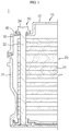
- FIG. 1 is a schematic diagram illustrating a battery module according to the related art.
- a battery module 1 may refer to a component in which a large number of secondary batteries 22 are connected in series or parallel for improving capacity, output, and the like.
- the battery module 1 includes a case 10 accommodating a secondary battery stacked body 20 in which the large number of secondary batteries 22 are stacked.
- the case 10 includes an upper case 12 accommodating an upper portion of the secondary battery stacked body 20 and a lower case 14 accommodating a lower portion of the secondary battery stacked body 20, and the upper case 12 and the lower case 14 are fastened to each other by a bolt 30.
- FIG. 1 shows that the case 10 includes an upper case 12 accommodating an upper portion of the secondary battery stacked body 20 and a lower case 14 accommodating a lower portion of the secondary battery stacked body 20, and the upper case 12 and the lower case 14 are fastened to each other by a bolt 30.
- the bolt 30 is mounted such that a screw portion 32 is inserted into a bolt hole 16 pierced in the upper case 12 and screw-coupled to the lower case 14, and that a bolt head 34 is caught by the upper case 12, thereby fastening the upper case 12 and the lower case to each other.
- an O-ring 40 is mounted to be interposed between the bolt head 34 and the upper case 12, thereby sealing the bolt hole 16.
- the O-ring 40 is mounted for the screw portion 32 of the bolt 30 to be inserted into a hollow thereof, and thus is interposed between the bolt head 34 and the upper case 12.
- the O-ring 40 generally has a smaller diameter than the bolt head 34, the bolt 30 needs to be separated from the bolt hole 16 for inspecting whether the O-ring 40 is mounted.
- the O-ring 40 is generally manufactured from a synthetic material having elasticity, there are some cases in which the O-ring 40 is twisted to be dragged toward the center thereof due to a shear force applied between the bolt head 34 and the O-ring 40 in the process of tightening the bolt 30. As such, when the O-ring 40 is twisted, the internal gas of the secondary batteries 22 may be leaked outside the battery module 1 through the bolt hole 16, like in the case that the O-ring 40 is not mounted. To inspect the twist of the O-ring 40, the bolt 30 needs to be separated from the bolt hole 16, like in the case of inspecting whether the O-ring 40 is mounted.
- the present disclosure is designed to solve the problems of the related art, and therefore the present disclosure is directed to providing a battery module, which has a structure improved to easily inspect whether an O-ring for preventing leakage of internal gas of a secondary battery is mounted and whether the O-ring is twisted, and a battery pack including the battery module.
- the present invention is defined by the features of claim 1, and relates to a battery module.
- a battery module comprising: a housing comprising a first housing and a second housing, which are coupled to each other to form a accommodation space; a plurality of secondary batteries accommodated in the accommodation space; a bolt comprising a screw portion, which has screw threads formed on at least a portion of an outer circumferential surface thereof, and a bolt head arranged at an end of the screw portion, the bolt being configured to fasten the first housing and the second housing to each other by being mounted such that the screw portion penetrates the first housing to be screw-coupled to the second housing, and that the bolt head is caught by the first housing; and an O-ring mounted to be interposed between the first housing and the bolt head, wherein the O-ring comprises: a hollow pierced such that the screw portion is inserted therein; and a recognition protrusion formed to protrude in a radial direction of the bolt head as compared with the bolt head.
- the O-ring has a diameter that is equal to or less than that of the bolt head.
- the recognition protrusion is formed to protrude from a circumferential surface of the O-ring in the radial direction of the bolt head.
- the first housing comprises a bolt hole pierced such that the screw portion is inserted therein, and the O-ring is interposed between the first housing and the bolt head to seal the bolt hole.
- the first housing comprises an O-ring groove formed to be recessed such that the O-ring is inserted therein.
- the O-ring groove has a recognition portion formed to extend in the radial direction of the bolt head such that the recognition protrusion is inserted therein.
- a battery module comprising: a housing comprising a accommodation space and a bolt hole; a plurality of secondary batteries accommodated in the accommodation space; a bolt comprising a screw portion and a bolt head arranged at an end of the screw portion, the bolt being mounted such that the screw portion is inserted into the bolt hole, and that the bolt head is caught by the housing; and an O-ring mounted to be interposed between the housing and the bolt head, wherein the O-ring comprises: a hollow pierced such that the screw portion is inserted therein; and a recognition protrusion formed to protrude in a radial direction of the bolt head as compared with the bolt head.
- the O-ring has a diameter that is equal to or less than that of the bolt head.
- a battery pack comprising the battery module according to the one aspect of the present disclosure as set forth above and the battery module according to the other aspect of the present disclosure as set forth above.
- a vehicle comprising the battery pack according to yet the other aspect of the present disclosure as set forth above.
- the recognition protrusion which protrudes in the radial direction of the bolt head as compared with the bolt head, is provided to the O-ring, whereby whether the O-ring is mounted and whether the O-ring is twisted may be checked by the recognition protrusion even without separating the bolt from the bolt hole.
- each component or the size of a specific portion constituting each component may be exaggerated, omitted, or schematically illustrated for convenience and clarity. Therefore, the size of each component does not completely reflect the actual size thereof.
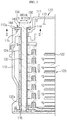
- FIG. 2 is a plan view illustrating a battery module according to a preferred embodiment of the present disclosure
- FIG. 3 is a partial cross-sectional view of the battery module of FIG. 2 , taken along a line I-I'
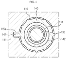
- FIG. 4 is a partial cross-sectional view of the battery module of FIG. 3 , taken along a line II-II'.
- a battery module 100 includes: a housing 110 including a first housing 111 and a second housing 112, which are coupled to each other to form a accommodation space 113; a secondary battery stacked body 120, which is obtained by stacking a plurality of secondary batteries 122 in multiple layers and is accommodated in the accommodation space 113 of the housing 110; a bolt 130 including a screw portion 132, which penetrates the first housing 111 to be screw-coupled to the second housing 112, and a bolt head 134 caught by the first housing 111, the bolt 130 being configured to fasten the first housing 111 and the second housing 112 to each other; and an O-ring 140 interposed between the bolt head 134 and the first housing 111 to prevent internal gas generated from the secondary batteries 122 from being leaked from the accommodation space of the housing 110.
- a plurality of battery modules 100 may be connected in a predetermined electrical connection method and constitute a battery pack.
- the battery pack may be mounted and used in vehicles.
- the housing 110 is a member for protecting the secondary batteries 122 from an outside thereof.
- the housing 110 is arranged to surround the secondary battery stacked body 120, and a battery management system (BMS) and other various members may be mounted on an outer surface of the housing 110.
- BMS battery management system
- the housing 110 includes the first housing 111 and the second housing 112, which are provided in the manner of being decouplable from and couplable to each other and form the accommodation space 113 for accommodating the secondary battery stacked body 120.
- the first housing 111 is arranged to surround an upper portion of the secondary battery stacked body 120. As shown in FIG. 3 , the first housing 111 includes a first bolt hole 114 pierced such that the screw portion 132 of the bolt 130 is inserted therein, and an O-ring groove 115 formed to be recessed such that the O-ring 140 is at least partially inserted therein.
- the first bolt hole 114 is formed by perforating the first housing 111 in an up-down direction such that the screw portion 132 of the bolt 130 is inserted into the first bolt hole 114.
- the first bolt hole 114 provides a path for the screw portion 132 of the bolt 130 to penetrate the accommodation space 113 and extend to the second housing 112.
- the O-ring groove 115 has a shape corresponding to the O-ring 140 for the O-ring 140 to be at least partially inserted into the O-ring groove 115, and is formed to be recessed on an upper surface of the first housing 111 to surround the first bolt hole 114.
- the O-ring groove 115 supports the O-ring 140 such that the O-ring 140 interposed between the bolt head 134 of the bolt 130 and the upper surface of the first housing 111 is not moved.
- the O-ring groove 115 includes a recognition portion 115a formed to extend such that a recognition protrusion 144 of the O-ring 140 described below is inserted into the recognition portion 115a.
- the recognition portion 115a is formed to extend from one side of the O-ring groove 115 in a radial direction of the bolt head 134, that is, in a radial direction of the O-ring 140.
- the second housing 112 is arranged to surround a lower portion of the secondary battery stacked body 120. As shown in FIG. 3 , the second housing 112 includes a second bolt hole 116 pierced such that a lower end of the screw portion 132 extending to the second housing 112 is screw-coupled thereto.
- the second bolt hole 116 is preferably formed on an upper surface of the second housing 112 such that only an upper portion of the second bolt hole 116 is opened and a lower portion thereof is closed, without being limited thereto.
- the secondary battery stacked body 120 is a member for providing electric power.
- the secondary battery stacked body 120 includes the plurality of secondary batteries 122 and a plurality of cartridges 124, each of the plurality of cartridges 124 accommodating at least one of the secondary batteries 122.
- Each of the secondary batteries 122 preferably includes a lithium polymer battery.
- each of the secondary batteries 122 may include a lithium ion battery, a nickel cadmium battery, a nickel metal hydride battery, a nickel zinc battery, or the like.
- Each of the secondary batteries 122 is preferably configured in a pouch type. However, the present disclosure is not limited thereto, and each of the secondary batteries 122 may be configured in a cylindrical type, an retangularr type, or the like.
- Each of the cartridges 124 accommodates and holds at least one of the secondary batteries 122, and thus prevents movements of the secondary batteries 122.
- the cartridges 124 may be mounted to be penetrated by the screw portion 132 of the bolt 130, and thus secured by the screw portion 132 of the bolt 130.
- the cartridges 124 are configured to be stackable on each other such that the secondary batteries 122 may be easily stacked and assembled.
- the cartridges 124 are stacked in multiple layers and thus form the secondary battery stacked body 120.
- FIG. 4 is a partial cross-sectional view of the battery module of FIG. 3 , taken along a line II-II'.
- the bolt 130 is a member for fastening the first housing 111 and the second housing 112 to each other.
- the bolt 130 includes the screw portion 132, which has screw threads formed on at least a portion of an outer circumferential surface thereof, and the bolt head 134 arranged at an end of the screw portion 132.
- the screw portion 132 has a predetermined length such that the lower end of the screw portion 132 sequentially passes through the first bolt hole 114 and the accommodation space 113 in this stated order and is screw-coupled to the second bolt hole 116.
- screw threads 132a of the screw portion 132 are preferably formed only on an outer circumferential surface of the lower end of the screw portion 132, which is screw-coupled to the second bolt hole 116, the present disclosure is not limited thereto.
- the bolt head 134 is arranged at an upper end of the screw portion 132, and has a larger diameter than the first bolt hole 114 not to be inserted into the first bolt hole 114.
- the bolt 130 may be mounted such that the screw portion 132 is screw-coupled to the second bolt hole 116, and that the bolt head 134 is caught by the upper surface of the first housing 111, thereby fastening the first housing 111 and the second housing 112 to each other.
- the O-ring 140 is a member for preventing the internal gas of the secondary batteries 122 from being leaked out of the housing 110.
- the O-ring 140 is preferably formed of a synthetic resin material having elasticity, without being limited thereto.
- the O-ring 140 includes a hollow 142 pierced such that the screw portion 132 is inserted therein, and the recognition protrusion 144 formed to protrude in the radial direction of the bolt head 134 as compared with the bolt head 134.
- the recognition protrusion 144 is preferably formed to protrude from a circumferential surface of the O-ring 140, without being limited thereto.
- the O-ring 140 is mounted in the O-ring groove 115 to be interposed between a bottom surface of the bolt head 134 and the upper surface of the first housing 111, and the recognition protrusion 144 is mounted to be inserted into the recognition portion 115a of the O-ring groove 115. Then, the O-ring 140 may seal the first bolt hole 114 and thus prevent the internal gas generated from the secondary batteries 122 from being leaked out of the housing 110 through the first bolt hole 114.
- the recognition protrusion 144 is accommodated in the recognition portion 115a to protrude in the radial direction of the bolt head 134 as compared with the bolt head 134.
- the recognition protrusion 144 is not accommodated in the recognition portion 115a or is only partially accommodated in the recognition portion 115a. Therefore, in the battery module 100, since whether the O-ring 140 is mounted and whether the O-ring 140 is twisted may be simultaneously checked by the recognition protrusion 144 even without separating the bolt 130 from the first bolt hole 114, productivity may be improved.
- the O-ring 140 has been described as being interposed between the first housing 11 and the bolt head 134 of the bolt 130 and being used to seal the first bolt hole 114 of the first housing 111, into which the screw portion 132 of the bolt 130 is inserted, the present disclosure is not limited thereto.
- the O-ring 140 may be interposed between the housing 110 and a bolt head (not shown) of the bolt and be used to seal a bolt hole (not shown) of the housing 110, into which a screw portion (not shown) of the bolt is inserted. Therefore, even in this case, like in the case of the bolt 130 set forth above, whether the O-ring 140 is mounted and whether the O-ring 140 is twisted may be simultaneously checked by the recognition protrusion 144 even without separating the bolt from the bolt hole.
- the present disclosure relates to a battery module and a battery pack including the battery module, and the battery module and the battery pack as set forth above may be particularly applied to industries related to secondary batteries.
Landscapes
- Engineering & Computer Science (AREA)
- General Engineering & Computer Science (AREA)
- Mechanical Engineering (AREA)
- Chemical Kinetics & Catalysis (AREA)
- Chemical & Material Sciences (AREA)
- Electrochemistry (AREA)
- General Chemical & Material Sciences (AREA)
- Power Engineering (AREA)
- Transportation (AREA)
- Sustainable Energy (AREA)
- Sustainable Development (AREA)
- Life Sciences & Earth Sciences (AREA)
- Battery Mounting, Suspending (AREA)
Description
- The present disclosure relates to a battery module and a battery pack including the same.
- Recently, as the demand for portable electronic products such as notebooks, video cameras, mobile phones, and the like is rapidly increased, and the development of electric vehicles, energy storage batteries, robots, satellite, and the like is accelerated, high-performance secondary batteries capable of being repeatedly charged and discharged are being actively studied.
- Currently commercialized secondary batteries include nickel cadmium batteries, nickel metal hydride batteries, nickel zinc batteries, lithium secondary batteries, and the like. Among these secondary batteries, since lithium secondary batteries have advantages of being freely charged and discharged due to almost no memory effect as compared with nickel-based batteries and having extremely low self-discharge rate and high energy density, lithium secondary batteries are spotlighted.
- Such lithium secondary batteries mainly include a lithium-based oxide and a carbon material as a positive electrode active material and a negative electrode active material, respectively. Lithium secondary batteries include an electrode assembly, in which a positive electrode plate and a negative electrode plate respectively coated with a positive electrode active material and an negative electrode active material are arranged with a separator therebetween, and an exterior, that is, a battery case, in which the electrode assembly and an electrolyte are sealed and accommodated.
- Generally, depending upon shapes of exteriors, lithium secondary batteries may be classified into can-type secondary batteries, in which an electrode assembly is embedded in a metal can, and pouch-type secondary batteries, in which an electrode assembly is embedded in a pouch of an aluminum laminate sheet.
- Recently, secondary batteries are widely used in medium and large-sized devices such as automobiles or power storage devices as well as in small-sized devices such as portable electronic devices. When secondary batteries are used in medium and large-sized devices, a large number of secondary batteries are electrically connected to each other for improving capacity and output. In particular, pouch-type secondary batteries are frequently used in medium and large-sized devices due to a merit of being easily accommodated and stacked. Document
WO2011/145547 discloses a battery module comprising a housing accommodating a plurality of battery units. -
FIG. 1 is a schematic diagram illustrating a battery module according to the related art. - As such, a
battery module 1 may refer to a component in which a large number ofsecondary batteries 22 are connected in series or parallel for improving capacity, output, and the like. Generally, thebattery module 1 includes acase 10 accommodating a secondary battery stackedbody 20 in which the large number ofsecondary batteries 22 are stacked. In addition, as shown inFIG. 1 , thecase 10 includes anupper case 12 accommodating an upper portion of the secondary battery stackedbody 20 and alower case 14 accommodating a lower portion of the secondary battery stackedbody 20, and theupper case 12 and thelower case 14 are fastened to each other by abolt 30. As shown inFIG. 1 , thebolt 30 is mounted such that ascrew portion 32 is inserted into abolt hole 16 pierced in theupper case 12 and screw-coupled to thelower case 14, and that abolt head 34 is caught by theupper case 12, thereby fastening theupper case 12 and the lower case to each other. - However, when internal gas is generated from the
secondary batteries 22 during charge-discharge of thesecondary batteries 22, there is a concern that the internal gas of thesecondary batteries 22 is leaked outside thebattery module 1 through thebolt hole 16 of theupper case 12. To solve this problem, in thebattery module 1 according to the related art, an O-ring 40 is mounted to be interposed between thebolt head 34 and theupper case 12, thereby sealing thebolt hole 16. The O-ring 40 is mounted for thescrew portion 32 of thebolt 30 to be inserted into a hollow thereof, and thus is interposed between thebolt head 34 and theupper case 12. However, since the O-ring 40 generally has a smaller diameter than thebolt head 34, thebolt 30 needs to be separated from thebolt hole 16 for inspecting whether the O-ring 40 is mounted. Therefore, in thebattery module 1 according to the related art, there are problems in that a lot of time is required for inspecting whether the O-ring 40 for sealing thebolt hole 16 is mounted, and that there is a concern of occurrence of errors in inspection results due to a complicated method of inspecting whether the O-ring 40 is mounted. - In addition, since the O-
ring 40 is generally manufactured from a synthetic material having elasticity, there are some cases in which the O-ring 40 is twisted to be dragged toward the center thereof due to a shear force applied between thebolt head 34 and the O-ring 40 in the process of tightening thebolt 30. As such, when the O-ring 40 is twisted, the internal gas of thesecondary batteries 22 may be leaked outside thebattery module 1 through thebolt hole 16, like in the case that the O-ring 40 is not mounted. To inspect the twist of the O-ring 40, thebolt 30 needs to be separated from thebolt hole 16, like in the case of inspecting whether the O-ring 40 is mounted. Therefore, in thebattery module 1 according to the related art, there are problems in that a lot of time is required for inspecting whether the O-ring 40 for sealing thebolt hole 16 is twisted, and that there is a concern of occurrence of errors in inspection results due to a complicated method of inspecting whether the O-ring 40 is twisted. - The present disclosure is designed to solve the problems of the related art, and therefore the present disclosure is directed to providing a battery module, which has a structure improved to easily inspect whether an O-ring for preventing leakage of internal gas of a secondary battery is mounted and whether the O-ring is twisted, and a battery pack including the battery module.
- The present invention is defined by the features of
claim 1, and relates to a battery module. - In one aspect of the present disclosure, there is provided a battery module comprising: a housing comprising a first housing and a second housing, which are coupled to each other to form a accommodation space; a plurality of secondary batteries accommodated in the accommodation space; a bolt comprising a screw portion, which has screw threads formed on at least a portion of an outer circumferential surface thereof, and a bolt head arranged at an end of the screw portion, the bolt being configured to fasten the first housing and the second housing to each other by being mounted such that the screw portion penetrates the first housing to be screw-coupled to the second housing, and that the bolt head is caught by the first housing; and an O-ring mounted to be interposed between the first housing and the bolt head, wherein the O-ring comprises: a hollow pierced such that the screw portion is inserted therein; and a recognition protrusion formed to protrude in a radial direction of the bolt head as compared with the bolt head.
- Preferably, the O-ring has a diameter that is equal to or less than that of the bolt head. Preferably, the recognition protrusion is formed to protrude from a circumferential surface of the O-ring in the radial direction of the bolt head.
- Preferably, the first housing comprises a bolt hole pierced such that the screw portion is inserted therein, and the O-ring is interposed between the first housing and the bolt head to seal the bolt hole.
- Preferably, the first housing comprises an O-ring groove formed to be recessed such that the O-ring is inserted therein.
- Preferably, the O-ring groove has a recognition portion formed to extend in the radial direction of the bolt head such that the recognition protrusion is inserted therein.
- In another aspect of the present disclosure, there is also provided a battery module comprising: a housing comprising a accommodation space and a bolt hole; a plurality of secondary batteries accommodated in the accommodation space; a bolt comprising a screw portion and a bolt head arranged at an end of the screw portion, the bolt being mounted such that the screw portion is inserted into the bolt hole, and that the bolt head is caught by the housing; and an O-ring mounted to be interposed between the housing and the bolt head, wherein the O-ring comprises: a hollow pierced such that the screw portion is inserted therein; and a recognition protrusion formed to protrude in a radial direction of the bolt head as compared with the bolt head.
- Preferably, the O-ring has a diameter that is equal to or less than that of the bolt head.
- In yet another aspect of the present disclosure, there is also provided a battery pack comprising the battery module according to the one aspect of the present disclosure as set forth above and the battery module according to the other aspect of the present disclosure as set forth above.
- In yet another aspect of the present disclosure, there is also provided a vehicle comprising the battery pack according to yet the other aspect of the present disclosure as set forth above.
- According to the battery module and the battery pack including the battery module according to the present disclosure, when the O-ring is interposed between the bolt head of the bolt and the housing to seal the bolt hole of the housing, into which the screw portion of the bolt is inserted, the recognition protrusion, which protrudes in the radial direction of the bolt head as compared with the bolt head, is provided to the O-ring, whereby whether the O-ring is mounted and whether the O-ring is twisted may be checked by the recognition protrusion even without separating the bolt from the bolt hole.
-
-
FIG. 1 is a schematic diagram illustrating a battery module according to the related art. -
FIG. 2 is a plan view illustrating a battery module according to a preferred embodiment of the present disclosure. -
FIG. 3 is a partial cross-sectional view of the battery module ofFIG. 2 , taken along a line I-I'. -
FIG. 4 is a partial cross-sectional view of the battery module ofFIG. 3 , taken along a line II-II'. - It should be understood that the terms used in the specification and the appended claims should not be construed as limited to general and dictionary meanings, but interpreted based on the meanings and concepts corresponding to technical aspects of the present disclosure on the basis of the principle that the inventor is allowed to define terms appropriately for the best explanation. Therefore, since embodiments described herein and configurations shown in the drawings are merely preferable examples and do not represent all technical aspects of the present disclosure, it should be understood that modified examples could be made without departing from the scope of the present claims.
- In the drawings, the size of each component or the size of a specific portion constituting each component may be exaggerated, omitted, or schematically illustrated for convenience and clarity. Therefore, the size of each component does not completely reflect the actual size thereof.
-
FIG. 2 is a plan view illustrating a battery module according to a preferred embodiment of the present disclosure,FIG. 3 is a partial cross-sectional view of the battery module ofFIG. 2 , taken along a line I-I', andFIG. 4 is a partial cross-sectional view of the battery module ofFIG. 3 , taken along a line II-II'. - Referring to
FIGS. 2 and3 , abattery module 100 according to a preferred embodiment of the present disclosure includes: ahousing 110 including afirst housing 111 and asecond housing 112, which are coupled to each other to form a accommodation space 113; a secondary battery stackedbody 120, which is obtained by stacking a plurality ofsecondary batteries 122 in multiple layers and is accommodated in the accommodation space 113 of thehousing 110; abolt 130 including ascrew portion 132, which penetrates thefirst housing 111 to be screw-coupled to thesecond housing 112, and abolt head 134 caught by thefirst housing 111, thebolt 130 being configured to fasten thefirst housing 111 and thesecond housing 112 to each other; and an O-ring 140 interposed between thebolt head 134 and thefirst housing 111 to prevent internal gas generated from thesecondary batteries 122 from being leaked from the accommodation space of thehousing 110. - A plurality of
battery modules 100 may be connected in a predetermined electrical connection method and constitute a battery pack. In addition, the battery pack may be mounted and used in vehicles. - First, the
housing 110 is a member for protecting thesecondary batteries 122 from an outside thereof. - As shown in
FIG. 2 , thehousing 110 is arranged to surround the secondary battery stackedbody 120, and a battery management system (BMS) and other various members may be mounted on an outer surface of thehousing 110. As shown inFIG. 3 , thehousing 110 includes thefirst housing 111 and thesecond housing 112, which are provided in the manner of being decouplable from and couplable to each other and form the accommodation space 113 for accommodating the secondary battery stackedbody 120. - As shown in
FIG. 3 , thefirst housing 111 is arranged to surround an upper portion of the secondary battery stackedbody 120. As shown inFIG. 3 , thefirst housing 111 includes afirst bolt hole 114 pierced such that thescrew portion 132 of thebolt 130 is inserted therein, and an O-ring groove 115 formed to be recessed such that the O-ring 140 is at least partially inserted therein. - As shown in
FIG. 3 , thefirst bolt hole 114 is formed by perforating thefirst housing 111 in an up-down direction such that thescrew portion 132 of thebolt 130 is inserted into thefirst bolt hole 114. Thefirst bolt hole 114 provides a path for thescrew portion 132 of thebolt 130 to penetrate the accommodation space 113 and extend to thesecond housing 112. - As shown in
FIG. 4 , the O-ring groove 115 has a shape corresponding to the O-ring 140 for the O-ring 140 to be at least partially inserted into the O-ring groove 115, and is formed to be recessed on an upper surface of thefirst housing 111 to surround thefirst bolt hole 114. The O-ring groove 115 supports the O-ring 140 such that the O-ring 140 interposed between thebolt head 134 of thebolt 130 and the upper surface of thefirst housing 111 is not moved. - In addition, as shown in
FIG. 4 , the O-ring groove 115 includes arecognition portion 115a formed to extend such that arecognition protrusion 144 of the O-ring 140 described below is inserted into therecognition portion 115a. Therecognition portion 115a is formed to extend from one side of the O-ring groove 115 in a radial direction of thebolt head 134, that is, in a radial direction of the O-ring 140. - As shown in
FIG. 3 , thesecond housing 112 is arranged to surround a lower portion of the secondary battery stackedbody 120. As shown inFIG. 3 , thesecond housing 112 includes asecond bolt hole 116 pierced such that a lower end of thescrew portion 132 extending to thesecond housing 112 is screw-coupled thereto. - As shown in
FIG. 3 , thesecond bolt hole 116 is preferably formed on an upper surface of thesecond housing 112 such that only an upper portion of thesecond bolt hole 116 is opened and a lower portion thereof is closed, without being limited thereto. - Next, the secondary battery stacked
body 120 is a member for providing electric power. - As shown in
FIG. 3 , the secondary battery stackedbody 120 includes the plurality ofsecondary batteries 122 and a plurality ofcartridges 124, each of the plurality ofcartridges 124 accommodating at least one of thesecondary batteries 122. - Each of the
secondary batteries 122 preferably includes a lithium polymer battery. However, the present disclosure is not limited thereto, and each of thesecondary batteries 122 may include a lithium ion battery, a nickel cadmium battery, a nickel metal hydride battery, a nickel zinc battery, or the like. - Each of the
secondary batteries 122 is preferably configured in a pouch type. However, the present disclosure is not limited thereto, and each of thesecondary batteries 122 may be configured in a cylindrical type, an retangularr type, or the like. - Each of the
cartridges 124 accommodates and holds at least one of thesecondary batteries 122, and thus prevents movements of thesecondary batteries 122. In addition, as shown inFIG. 3 , thecartridges 124 may be mounted to be penetrated by thescrew portion 132 of thebolt 130, and thus secured by thescrew portion 132 of thebolt 130. Thecartridges 124 are configured to be stackable on each other such that thesecondary batteries 122 may be easily stacked and assembled. Thus, thecartridges 124 are stacked in multiple layers and thus form the secondary battery stackedbody 120. -
FIG. 4 is a partial cross-sectional view of the battery module ofFIG. 3 , taken along a line II-II'. - Next, the
bolt 130 is a member for fastening thefirst housing 111 and thesecond housing 112 to each other. - As shown in
FIG. 3 , thebolt 130 includes thescrew portion 132, which has screw threads formed on at least a portion of an outer circumferential surface thereof, and thebolt head 134 arranged at an end of thescrew portion 132. - The
screw portion 132 has a predetermined length such that the lower end of thescrew portion 132 sequentially passes through thefirst bolt hole 114 and the accommodation space 113 in this stated order and is screw-coupled to thesecond bolt hole 116. Althoughscrew threads 132a of thescrew portion 132 are preferably formed only on an outer circumferential surface of the lower end of thescrew portion 132, which is screw-coupled to thesecond bolt hole 116, the present disclosure is not limited thereto. - The
bolt head 134 is arranged at an upper end of thescrew portion 132, and has a larger diameter than thefirst bolt hole 114 not to be inserted into thefirst bolt hole 114. - As shown in
FIG. 3 , thebolt 130 may be mounted such that thescrew portion 132 is screw-coupled to thesecond bolt hole 116, and that thebolt head 134 is caught by the upper surface of thefirst housing 111, thereby fastening thefirst housing 111 and thesecond housing 112 to each other. - Next, the O-
ring 140 is a member for preventing the internal gas of thesecondary batteries 122 from being leaked out of thehousing 110. - The O-
ring 140 is preferably formed of a synthetic resin material having elasticity, without being limited thereto. As shown inFIG. 4 , the O-ring 140 includes a hollow 142 pierced such that thescrew portion 132 is inserted therein, and therecognition protrusion 144 formed to protrude in the radial direction of thebolt head 134 as compared with thebolt head 134. In addition, as shown inFIG. 4 , therecognition protrusion 144 is preferably formed to protrude from a circumferential surface of the O-ring 140, without being limited thereto. - The O-
ring 140 is mounted in the O-ring groove 115 to be interposed between a bottom surface of thebolt head 134 and the upper surface of thefirst housing 111, and therecognition protrusion 144 is mounted to be inserted into therecognition portion 115a of the O-ring groove 115. Then, the O-ring 140 may seal thefirst bolt hole 114 and thus prevent the internal gas generated from thesecondary batteries 122 from being leaked out of thehousing 110 through thefirst bolt hole 114. - In the case that the O-
ring 140 is normally mounted, when the upper surface of thefirst housing 111 is viewed from an outside of thebattery module 100, therecognition protrusion 144 is accommodated in therecognition portion 115a to protrude in the radial direction of thebolt head 134 as compared with thebolt head 134. On the other hand, in the case that the O-ring 140 is not mounted due to process errors or other causes or is twisted due to a shear force applied upon mounting thebolt 130, when the upper surface of thefirst housing 111 is viewed from the outside of thebattery module 100, therecognition protrusion 144 is not accommodated in therecognition portion 115a or is only partially accommodated in therecognition portion 115a. Therefore, in thebattery module 100, since whether the O-ring 140 is mounted and whether the O-ring 140 is twisted may be simultaneously checked by therecognition protrusion 144 even without separating thebolt 130 from thefirst bolt hole 114, productivity may be improved. - Although, when the
bolt 130 is mounted for fastening thefirst housing 111 and thesecond housing 112 to each other, the O-ring 140 has been described as being interposed between the first housing 11 and thebolt head 134 of thebolt 130 and being used to seal thefirst bolt hole 114 of thefirst housing 111, into which thescrew portion 132 of thebolt 130 is inserted, the present disclosure is not limited thereto. That is, when a bolt (not shown) different from thebolt 130 set forth above is mounted in thehousing 110 for purposes other than the purpose of fastening thefirst housing 111 and thesecond housing 112 to each other, the O-ring 140 may be interposed between thehousing 110 and a bolt head (not shown) of the bolt and be used to seal a bolt hole (not shown) of thehousing 110, into which a screw portion (not shown) of the bolt is inserted. Therefore, even in this case, like in the case of thebolt 130 set forth above, whether the O-ring 140 is mounted and whether the O-ring 140 is twisted may be simultaneously checked by therecognition protrusion 144 even without separating the bolt from the bolt hole. - Heretofore, although the present disclosure has been described with reference to specific embodiments in conjunction with the accompanying drawings, it should be understood that the present disclosure is not limited by these embodiments, and that various modifications and changes can be made by those skilled in the art without departing from the scope of the present claims.
- The present disclosure relates to a battery module and a battery pack including the battery module, and the battery module and the battery pack as set forth above may be particularly applied to industries related to secondary batteries.
Claims (6)
- A battery module (100) comprising:a housing (110) comprising a first housing (111) and a second housing (112), which are coupled to each other to form a accommodation space (113);a plurality of secondary batteries (122) accommodated in the accommodation space (113);a bolt (130) comprising a screw portion (132) and a bolt head (134) arranged at an end of the screw portion (132), the bolt (130) being configured to fasten the first housing (111) and the second housing (112) to each other by being mounted such that the screw portion (132) penetrates the first housing (111) to be screw-coupled to the second housing (112), and that the bolt head (134) is caught by the first housing (111); andan O-ring (140) mounted to be interposed between the first housing (111) and the bolt head (134),wherein the O-ring (140) comprises:a hollow pierced such that the screw portion is inserted therein; anda recognition protrusion (144) formed to protrude in a radial direction of the bolt head (134) as compared with the bolt head (134),wherein the first housing (111) comprises an O-ring groove (115) formed to be recessed such that the O-ring (140) is inserted therein, andwherein the O-ring groove (115) has a recognition portion (115a) formed to extend in the radial direction of the bolt head (134) such that the recognition protrusion (144) is inserted therein.
- The battery module (100) according to claim 1, wherein the O-ring (140) has a diameter that is equal to or less than that of the bolt head (134).
- The battery module (100) according to claim 1, wherein the recognition protrusion (144) is formed to protrude from a circumferential surface of the O-ring (140) in the radial direction of the bolt head (134).
- The battery module (100) according to claim 1, wherein the first housing (111) comprises a bolt hole (114) pierced such that the screw portion (132) is inserted therein, and
the O-ring (140) is interposed between the first housing (111) and the bolt head (134) to seal the bolt hole (114). - A battery pack comprising the battery module (100) according to any one of claims 1 to 4.
- A vehicle comprising the battery pack according to claim 5.
Priority Applications (1)
| Application Number | Priority Date | Filing Date | Title |
|---|---|---|---|
| PL17747645T PL3306704T3 (en) | 2016-02-05 | 2017-01-19 | Battery module and battery pack comprising same |
Applications Claiming Priority (2)
| Application Number | Priority Date | Filing Date | Title |
|---|---|---|---|
| KR1020160015160A KR102017232B1 (en) | 2016-02-05 | 2016-02-05 | Battery module and battery pack having the same |
| PCT/KR2017/000686 WO2017135600A1 (en) | 2016-02-05 | 2017-01-19 | Battery module and battery pack comprising same |
Publications (3)
| Publication Number | Publication Date |
|---|---|
| EP3306704A1 EP3306704A1 (en) | 2018-04-11 |
| EP3306704A4 EP3306704A4 (en) | 2018-05-23 |
| EP3306704B1 true EP3306704B1 (en) | 2020-03-11 |
Family
ID=59500046
Family Applications (1)
| Application Number | Title | Priority Date | Filing Date |
|---|---|---|---|
| EP17747645.4A Active EP3306704B1 (en) | 2016-02-05 | 2017-01-19 | Battery module and battery pack comprising same |
Country Status (7)
| Country | Link |
|---|---|
| US (1) | US10396325B2 (en) |
| EP (1) | EP3306704B1 (en) |
| JP (1) | JP6538275B2 (en) |
| KR (1) | KR102017232B1 (en) |
| CN (1) | CN107851758B (en) |
| PL (1) | PL3306704T3 (en) |
| WO (1) | WO2017135600A1 (en) |
Families Citing this family (3)
| Publication number | Priority date | Publication date | Assignee | Title |
|---|---|---|---|---|
| KR102349342B1 (en) * | 2017-12-15 | 2022-01-07 | 주식회사 엘지에너지솔루션 | Disassembling tool and battery module using the same |
| US10476060B1 (en) * | 2018-06-07 | 2019-11-12 | Ford Global Technologies, Llc | Sealed structural pass through assemblies for electrified vehicle battery packs |
| US11996569B2 (en) * | 2020-09-02 | 2024-05-28 | Hyundai Mobis Co., Ltd. | High voltage battery protection pack |
Family Cites Families (18)
| Publication number | Priority date | Publication date | Assignee | Title |
|---|---|---|---|---|
| US5031924A (en) * | 1989-11-30 | 1991-07-16 | Blackstone Corporation | Twist indicator gasket |
| KR0177214B1 (en) * | 1995-12-29 | 1999-05-15 | 배순훈 | Gasket tester of li/mno2 battery |
| JP3894182B2 (en) * | 2003-10-10 | 2007-03-14 | 日産自動車株式会社 | Assembled battery |
| JP2005122917A (en) * | 2003-10-14 | 2005-05-12 | Mitsutoyo Corp | Housing body, battery housing part, and measuring instrument and electronic device |
| KR100907990B1 (en) * | 2007-10-04 | 2009-07-16 | 지엠대우오토앤테크놀로지주식회사 | Gasket for mounting confirmation |
| US8002957B2 (en) * | 2008-01-02 | 2011-08-23 | General Electric Company | Sensor apparatus for measuring and detecting acetylene and hydrogen dissolved in a fluid |
| DE102009005124A1 (en) * | 2009-01-19 | 2010-07-29 | Li-Tec Battery Gmbh | Electrochemical energy storage device |
| CN101567427B (en) * | 2009-06-05 | 2011-08-03 | 深圳市科达利实业股份有限公司 | Battery cathode sealing device |
| JP5626852B2 (en) * | 2010-05-19 | 2014-11-19 | Necエナジーデバイス株式会社 | Power supply |
| KR101177764B1 (en) | 2010-07-21 | 2012-08-30 | (주)이화테크원 | O-RING bolt prosecuting attorney system |
| KR20130099975A (en) * | 2010-09-21 | 2013-09-06 | 신코베덴키 가부시키가이샤 | Nonaqueous electrolyte secondary battery |
| JP5932990B2 (en) | 2011-06-27 | 2016-06-08 | エルジー・ケム・リミテッド | Battery module and battery assembly including the same |
| KR101359306B1 (en) * | 2011-06-27 | 2014-02-21 | 주식회사 엘지화학 | Battery Module Assembly and Battery Pack Comprising the Same |
| KR20130017289A (en) * | 2011-08-10 | 2013-02-20 | 현대자동차주식회사 | Side air bag apparatus for vehicle |
| JP2013229182A (en) * | 2012-04-25 | 2013-11-07 | Sanyo Electric Co Ltd | Power supply device, vehicle including power supply device, and power storage device |
| US9306199B2 (en) * | 2012-08-16 | 2016-04-05 | Lg Chem, Ltd. | Battery module and method for assembling the battery module |
| KR20160015160A (en) | 2014-07-30 | 2016-02-12 | 스미또모 가가꾸 가부시키가이샤 | Anti-glare film |
| CN204333063U (en) * | 2014-12-02 | 2015-05-13 | 上海航天电源技术有限责任公司 | A kind of electrokinetic cell system Housing seal arrangement |
-
2016
- 2016-02-05 KR KR1020160015160A patent/KR102017232B1/en active IP Right Grant
-
2017
- 2017-01-19 CN CN201780002314.7A patent/CN107851758B/en active Active
- 2017-01-19 EP EP17747645.4A patent/EP3306704B1/en active Active
- 2017-01-19 WO PCT/KR2017/000686 patent/WO2017135600A1/en active Application Filing
- 2017-01-19 US US15/736,454 patent/US10396325B2/en active Active
- 2017-01-19 PL PL17747645T patent/PL3306704T3/en unknown
- 2017-01-19 JP JP2018517330A patent/JP6538275B2/en active Active
Non-Patent Citations (1)
| Title |
|---|
| None * |
Also Published As
| Publication number | Publication date |
|---|---|
| JP6538275B2 (en) | 2019-07-03 |
| EP3306704A1 (en) | 2018-04-11 |
| PL3306704T3 (en) | 2020-07-27 |
| EP3306704A4 (en) | 2018-05-23 |
| KR20170093578A (en) | 2017-08-16 |
| US10396325B2 (en) | 2019-08-27 |
| WO2017135600A1 (en) | 2017-08-10 |
| JP2018534732A (en) | 2018-11-22 |
| US20180175351A1 (en) | 2018-06-21 |
| KR102017232B1 (en) | 2019-09-02 |
| CN107851758A (en) | 2018-03-27 |
| CN107851758B (en) | 2020-11-10 |
Similar Documents
| Publication | Publication Date | Title |
|---|---|---|
| JP6496455B2 (en) | Battery module and battery pack including the same | |
| JP6166994B2 (en) | Assembled battery | |
| US9093699B2 (en) | Rechargeable battery | |
| US10971778B2 (en) | Battery pack | |
| US9853294B2 (en) | Secondary battery and manufacturing method thereof | |
| EP3297061B1 (en) | Battery pack | |
| CN108232045B (en) | Battery and battery pack | |
| EP3306704B1 (en) | Battery module and battery pack comprising same | |
| EP2602841B1 (en) | Battery | |
| EP4044355A1 (en) | Electrode assembly and manufacturing method therefor | |
| US10079372B2 (en) | Secondary battery and fabricating method thereof | |
| KR20200103474A (en) | The Apparatus For Venting | |
| US11699832B2 (en) | Battery module | |
| KR20200055336A (en) | Battery pack | |
| EP4199225A1 (en) | Battery module, and battery pack and vehicle comprising same | |
| US20240274893A1 (en) | Cell core, battery cell, battery, and electric device | |
| KR20150066159A (en) | Can assay of litium ion battery with high capacity and power | |
| KR20190112570A (en) | Battery cell cartridge having uniformity surface pressure |
Legal Events
| Date | Code | Title | Description |
|---|---|---|---|
| STAA | Information on the status of an ep patent application or granted ep patent |
Free format text: STATUS: THE INTERNATIONAL PUBLICATION HAS BEEN MADE |
|
| PUAI | Public reference made under article 153(3) epc to a published international application that has entered the european phase |
Free format text: ORIGINAL CODE: 0009012 |
|
| STAA | Information on the status of an ep patent application or granted ep patent |
Free format text: STATUS: REQUEST FOR EXAMINATION WAS MADE |
|
| 17P | Request for examination filed |
Effective date: 20180103 |
|
| AK | Designated contracting states |
Kind code of ref document: A1 Designated state(s): AL AT BE BG CH CY CZ DE DK EE ES FI FR GB GR HR HU IE IS IT LI LT LU LV MC MK MT NL NO PL PT RO RS SE SI SK SM TR |
|
| AX | Request for extension of the european patent |
Extension state: BA ME |
|
| A4 | Supplementary search report drawn up and despatched |
Effective date: 20180420 |
|
| RIC1 | Information provided on ipc code assigned before grant |
Ipc: H01M 2/10 20060101AFI20180416BHEP Ipc: B60L 11/18 20060101ALI20180416BHEP |
|
| DAV | Request for validation of the european patent (deleted) | ||
| DAX | Request for extension of the european patent (deleted) | ||
| GRAP | Despatch of communication of intention to grant a patent |
Free format text: ORIGINAL CODE: EPIDOSNIGR1 |
|
| STAA | Information on the status of an ep patent application or granted ep patent |
Free format text: STATUS: GRANT OF PATENT IS INTENDED |
|
| RIC1 | Information provided on ipc code assigned before grant |
Ipc: H01M 2/10 20060101AFI20191127BHEP Ipc: B60L 50/64 20190101ALI20191127BHEP Ipc: B60L 50/60 20190101ALI20191127BHEP |
|
| INTG | Intention to grant announced |
Effective date: 20191213 |
|
| GRAS | Grant fee paid |
Free format text: ORIGINAL CODE: EPIDOSNIGR3 |
|
| GRAA | (expected) grant |
Free format text: ORIGINAL CODE: 0009210 |
|
| STAA | Information on the status of an ep patent application or granted ep patent |
Free format text: STATUS: THE PATENT HAS BEEN GRANTED |
|
| AK | Designated contracting states |
Kind code of ref document: B1 Designated state(s): AL AT BE BG CH CY CZ DE DK EE ES FI FR GB GR HR HU IE IS IT LI LT LU LV MC MK MT NL NO PL PT RO RS SE SI SK SM TR |
|
| REG | Reference to a national code |
Ref country code: GB Ref legal event code: FG4D |
|
| REG | Reference to a national code |
Ref country code: CH Ref legal event code: EP |
|
| REG | Reference to a national code |
Ref country code: AT Ref legal event code: REF Ref document number: 1244283 Country of ref document: AT Kind code of ref document: T Effective date: 20200315 |
|
| REG | Reference to a national code |
Ref country code: IE Ref legal event code: FG4D |
|
| REG | Reference to a national code |
Ref country code: DE Ref legal event code: R096 Ref document number: 602017013048 Country of ref document: DE |
|
| PG25 | Lapsed in a contracting state [announced via postgrant information from national office to epo] |
Ref country code: NO Free format text: LAPSE BECAUSE OF FAILURE TO SUBMIT A TRANSLATION OF THE DESCRIPTION OR TO PAY THE FEE WITHIN THE PRESCRIBED TIME-LIMIT Effective date: 20200611 Ref country code: FI Free format text: LAPSE BECAUSE OF FAILURE TO SUBMIT A TRANSLATION OF THE DESCRIPTION OR TO PAY THE FEE WITHIN THE PRESCRIBED TIME-LIMIT Effective date: 20200311 Ref country code: RS Free format text: LAPSE BECAUSE OF FAILURE TO SUBMIT A TRANSLATION OF THE DESCRIPTION OR TO PAY THE FEE WITHIN THE PRESCRIBED TIME-LIMIT Effective date: 20200311 |
|
| REG | Reference to a national code |
Ref country code: NL Ref legal event code: MP Effective date: 20200311 |
|
| PG25 | Lapsed in a contracting state [announced via postgrant information from national office to epo] |
Ref country code: HR Free format text: LAPSE BECAUSE OF FAILURE TO SUBMIT A TRANSLATION OF THE DESCRIPTION OR TO PAY THE FEE WITHIN THE PRESCRIBED TIME-LIMIT Effective date: 20200311 Ref country code: GR Free format text: LAPSE BECAUSE OF FAILURE TO SUBMIT A TRANSLATION OF THE DESCRIPTION OR TO PAY THE FEE WITHIN THE PRESCRIBED TIME-LIMIT Effective date: 20200612 Ref country code: SE Free format text: LAPSE BECAUSE OF FAILURE TO SUBMIT A TRANSLATION OF THE DESCRIPTION OR TO PAY THE FEE WITHIN THE PRESCRIBED TIME-LIMIT Effective date: 20200311 Ref country code: BG Free format text: LAPSE BECAUSE OF FAILURE TO SUBMIT A TRANSLATION OF THE DESCRIPTION OR TO PAY THE FEE WITHIN THE PRESCRIBED TIME-LIMIT Effective date: 20200611 Ref country code: LV Free format text: LAPSE BECAUSE OF FAILURE TO SUBMIT A TRANSLATION OF THE DESCRIPTION OR TO PAY THE FEE WITHIN THE PRESCRIBED TIME-LIMIT Effective date: 20200311 |
|
| REG | Reference to a national code |
Ref country code: LT Ref legal event code: MG4D |
|
| PG25 | Lapsed in a contracting state [announced via postgrant information from national office to epo] |
Ref country code: NL Free format text: LAPSE BECAUSE OF FAILURE TO SUBMIT A TRANSLATION OF THE DESCRIPTION OR TO PAY THE FEE WITHIN THE PRESCRIBED TIME-LIMIT Effective date: 20200311 |
|
| PG25 | Lapsed in a contracting state [announced via postgrant information from national office to epo] |
Ref country code: RO Free format text: LAPSE BECAUSE OF FAILURE TO SUBMIT A TRANSLATION OF THE DESCRIPTION OR TO PAY THE FEE WITHIN THE PRESCRIBED TIME-LIMIT Effective date: 20200311 Ref country code: CZ Free format text: LAPSE BECAUSE OF FAILURE TO SUBMIT A TRANSLATION OF THE DESCRIPTION OR TO PAY THE FEE WITHIN THE PRESCRIBED TIME-LIMIT Effective date: 20200311 Ref country code: PT Free format text: LAPSE BECAUSE OF FAILURE TO SUBMIT A TRANSLATION OF THE DESCRIPTION OR TO PAY THE FEE WITHIN THE PRESCRIBED TIME-LIMIT Effective date: 20200805 Ref country code: IS Free format text: LAPSE BECAUSE OF FAILURE TO SUBMIT A TRANSLATION OF THE DESCRIPTION OR TO PAY THE FEE WITHIN THE PRESCRIBED TIME-LIMIT Effective date: 20200711 Ref country code: SK Free format text: LAPSE BECAUSE OF FAILURE TO SUBMIT A TRANSLATION OF THE DESCRIPTION OR TO PAY THE FEE WITHIN THE PRESCRIBED TIME-LIMIT Effective date: 20200311 Ref country code: SM Free format text: LAPSE BECAUSE OF FAILURE TO SUBMIT A TRANSLATION OF THE DESCRIPTION OR TO PAY THE FEE WITHIN THE PRESCRIBED TIME-LIMIT Effective date: 20200311 Ref country code: EE Free format text: LAPSE BECAUSE OF FAILURE TO SUBMIT A TRANSLATION OF THE DESCRIPTION OR TO PAY THE FEE WITHIN THE PRESCRIBED TIME-LIMIT Effective date: 20200311 Ref country code: LT Free format text: LAPSE BECAUSE OF FAILURE TO SUBMIT A TRANSLATION OF THE DESCRIPTION OR TO PAY THE FEE WITHIN THE PRESCRIBED TIME-LIMIT Effective date: 20200311 |
|
| REG | Reference to a national code |
Ref country code: AT Ref legal event code: MK05 Ref document number: 1244283 Country of ref document: AT Kind code of ref document: T Effective date: 20200311 |
|
| REG | Reference to a national code |
Ref country code: DE Ref legal event code: R079 Ref document number: 602017013048 Country of ref document: DE Free format text: PREVIOUS MAIN CLASS: H01M0002100000 Ipc: H01M0050200000 |
|
| REG | Reference to a national code |
Ref country code: DE Ref legal event code: R097 Ref document number: 602017013048 Country of ref document: DE |
|
| PLBE | No opposition filed within time limit |
Free format text: ORIGINAL CODE: 0009261 |
|
| STAA | Information on the status of an ep patent application or granted ep patent |
Free format text: STATUS: NO OPPOSITION FILED WITHIN TIME LIMIT |
|
| PG25 | Lapsed in a contracting state [announced via postgrant information from national office to epo] |
Ref country code: ES Free format text: LAPSE BECAUSE OF FAILURE TO SUBMIT A TRANSLATION OF THE DESCRIPTION OR TO PAY THE FEE WITHIN THE PRESCRIBED TIME-LIMIT Effective date: 20200311 Ref country code: DK Free format text: LAPSE BECAUSE OF FAILURE TO SUBMIT A TRANSLATION OF THE DESCRIPTION OR TO PAY THE FEE WITHIN THE PRESCRIBED TIME-LIMIT Effective date: 20200311 Ref country code: AT Free format text: LAPSE BECAUSE OF FAILURE TO SUBMIT A TRANSLATION OF THE DESCRIPTION OR TO PAY THE FEE WITHIN THE PRESCRIBED TIME-LIMIT Effective date: 20200311 Ref country code: IT Free format text: LAPSE BECAUSE OF FAILURE TO SUBMIT A TRANSLATION OF THE DESCRIPTION OR TO PAY THE FEE WITHIN THE PRESCRIBED TIME-LIMIT Effective date: 20200311 |
|
| 26N | No opposition filed |
Effective date: 20201214 |
|
| PG25 | Lapsed in a contracting state [announced via postgrant information from national office to epo] |
Ref country code: SI Free format text: LAPSE BECAUSE OF FAILURE TO SUBMIT A TRANSLATION OF THE DESCRIPTION OR TO PAY THE FEE WITHIN THE PRESCRIBED TIME-LIMIT Effective date: 20200311 |
|
| PG25 | Lapsed in a contracting state [announced via postgrant information from national office to epo] |
Ref country code: MC Free format text: LAPSE BECAUSE OF FAILURE TO SUBMIT A TRANSLATION OF THE DESCRIPTION OR TO PAY THE FEE WITHIN THE PRESCRIBED TIME-LIMIT Effective date: 20200311 |
|
| REG | Reference to a national code |
Ref country code: CH Ref legal event code: PL |
|
| PG25 | Lapsed in a contracting state [announced via postgrant information from national office to epo] |
Ref country code: LU Free format text: LAPSE BECAUSE OF NON-PAYMENT OF DUE FEES Effective date: 20210119 |
|
| REG | Reference to a national code |
Ref country code: BE Ref legal event code: MM Effective date: 20210131 |
|
| PG25 | Lapsed in a contracting state [announced via postgrant information from national office to epo] |
Ref country code: LI Free format text: LAPSE BECAUSE OF NON-PAYMENT OF DUE FEES Effective date: 20210131 Ref country code: CH Free format text: LAPSE BECAUSE OF NON-PAYMENT OF DUE FEES Effective date: 20210131 |
|
| PG25 | Lapsed in a contracting state [announced via postgrant information from national office to epo] |
Ref country code: IE Free format text: LAPSE BECAUSE OF NON-PAYMENT OF DUE FEES Effective date: 20210119 |
|
| PG25 | Lapsed in a contracting state [announced via postgrant information from national office to epo] |
Ref country code: BE Free format text: LAPSE BECAUSE OF NON-PAYMENT OF DUE FEES Effective date: 20210131 |
|
| REG | Reference to a national code |
Ref country code: DE Ref legal event code: R081 Ref document number: 602017013048 Country of ref document: DE Owner name: LG ENERGY SOLUTION, LTD., KR Free format text: FORMER OWNER: LG CHEM, LTD., SEOUL, KR |
|
| P01 | Opt-out of the competence of the unified patent court (upc) registered |
Effective date: 20230512 |
|
| PG25 | Lapsed in a contracting state [announced via postgrant information from national office to epo] |
Ref country code: CY Free format text: LAPSE BECAUSE OF FAILURE TO SUBMIT A TRANSLATION OF THE DESCRIPTION OR TO PAY THE FEE WITHIN THE PRESCRIBED TIME-LIMIT Effective date: 20200311 |
|
| PG25 | Lapsed in a contracting state [announced via postgrant information from national office to epo] |
Ref country code: HU Free format text: LAPSE BECAUSE OF FAILURE TO SUBMIT A TRANSLATION OF THE DESCRIPTION OR TO PAY THE FEE WITHIN THE PRESCRIBED TIME-LIMIT; INVALID AB INITIO Effective date: 20170119 |
|
| REG | Reference to a national code |
Ref country code: GB Ref legal event code: 732E Free format text: REGISTERED BETWEEN 20230824 AND 20230831 |
|
| PGFP | Annual fee paid to national office [announced via postgrant information from national office to epo] |
Ref country code: GB Payment date: 20231220 Year of fee payment: 8 |
|
| PGFP | Annual fee paid to national office [announced via postgrant information from national office to epo] |
Ref country code: FR Payment date: 20231222 Year of fee payment: 8 |
|
| PGFP | Annual fee paid to national office [announced via postgrant information from national office to epo] |
Ref country code: PL Payment date: 20231222 Year of fee payment: 8 |
|
| PG25 | Lapsed in a contracting state [announced via postgrant information from national office to epo] |
Ref country code: MK Free format text: LAPSE BECAUSE OF FAILURE TO SUBMIT A TRANSLATION OF THE DESCRIPTION OR TO PAY THE FEE WITHIN THE PRESCRIBED TIME-LIMIT Effective date: 20200311 |
|
| PGFP | Annual fee paid to national office [announced via postgrant information from national office to epo] |
Ref country code: DE Payment date: 20231220 Year of fee payment: 8 |
|
| PG25 | Lapsed in a contracting state [announced via postgrant information from national office to epo] |
Ref country code: MT Free format text: LAPSE BECAUSE OF FAILURE TO SUBMIT A TRANSLATION OF THE DESCRIPTION OR TO PAY THE FEE WITHIN THE PRESCRIBED TIME-LIMIT Effective date: 20200311 |