EP3306569B1 - Verfahren, systeme und computerlesbare medien für diffuse globale beleuchtung mit sonden - Google Patents
Verfahren, systeme und computerlesbare medien für diffuse globale beleuchtung mit sonden Download PDFInfo
- Publication number
- EP3306569B1 EP3306569B1 EP16204196.6A EP16204196A EP3306569B1 EP 3306569 B1 EP3306569 B1 EP 3306569B1 EP 16204196 A EP16204196 A EP 16204196A EP 3306569 B1 EP3306569 B1 EP 3306569B1
- Authority
- EP
- European Patent Office
- Prior art keywords
- probes
- probe
- game
- determining
- computer
- Prior art date
- Legal status (The legal status is an assumption and is not a legal conclusion. Google has not performed a legal analysis and makes no representation as to the accuracy of the status listed.)
- Active
Links
Images





Classifications
-
- A—HUMAN NECESSITIES
- A63—SPORTS; GAMES; AMUSEMENTS
- A63F—CARD, BOARD, OR ROULETTE GAMES; INDOOR GAMES USING SMALL MOVING PLAYING BODIES; VIDEO GAMES; GAMES NOT OTHERWISE PROVIDED FOR
- A63F13/00—Video games, i.e. games using an electronically generated display having two or more dimensions
- A63F13/50—Controlling the output signals based on the game progress
- A63F13/52—Controlling the output signals based on the game progress involving aspects of the displayed game scene
-
- A—HUMAN NECESSITIES
- A63—SPORTS; GAMES; AMUSEMENTS
- A63F—CARD, BOARD, OR ROULETTE GAMES; INDOOR GAMES USING SMALL MOVING PLAYING BODIES; VIDEO GAMES; GAMES NOT OTHERWISE PROVIDED FOR
- A63F13/00—Video games, i.e. games using an electronically generated display having two or more dimensions
- A63F13/50—Controlling the output signals based on the game progress
- A63F13/52—Controlling the output signals based on the game progress involving aspects of the displayed game scene
- A63F13/525—Changing parameters of virtual cameras
-
- A—HUMAN NECESSITIES
- A63—SPORTS; GAMES; AMUSEMENTS
- A63F—CARD, BOARD, OR ROULETTE GAMES; INDOOR GAMES USING SMALL MOVING PLAYING BODIES; VIDEO GAMES; GAMES NOT OTHERWISE PROVIDED FOR
- A63F13/00—Video games, i.e. games using an electronically generated display having two or more dimensions
- A63F13/20—Input arrangements for video game devices
-
- A—HUMAN NECESSITIES
- A63—SPORTS; GAMES; AMUSEMENTS
- A63F—CARD, BOARD, OR ROULETTE GAMES; INDOOR GAMES USING SMALL MOVING PLAYING BODIES; VIDEO GAMES; GAMES NOT OTHERWISE PROVIDED FOR
- A63F13/00—Video games, i.e. games using an electronically generated display having two or more dimensions
- A63F13/25—Output arrangements for video game devices
-
- A—HUMAN NECESSITIES
- A63—SPORTS; GAMES; AMUSEMENTS
- A63F—CARD, BOARD, OR ROULETTE GAMES; INDOOR GAMES USING SMALL MOVING PLAYING BODIES; VIDEO GAMES; GAMES NOT OTHERWISE PROVIDED FOR
- A63F13/00—Video games, i.e. games using an electronically generated display having two or more dimensions
- A63F13/40—Processing input control signals of video game devices, e.g. signals generated by the player or derived from the environment
-
- A—HUMAN NECESSITIES
- A63—SPORTS; GAMES; AMUSEMENTS
- A63F—CARD, BOARD, OR ROULETTE GAMES; INDOOR GAMES USING SMALL MOVING PLAYING BODIES; VIDEO GAMES; GAMES NOT OTHERWISE PROVIDED FOR
- A63F13/00—Video games, i.e. games using an electronically generated display having two or more dimensions
- A63F13/90—Constructional details or arrangements of video game devices not provided for in groups A63F13/20 or A63F13/25, e.g. housing, wiring, connections or cabinets
-
- G—PHYSICS
- G01—MEASURING; TESTING
- G01J—MEASUREMENT OF INTENSITY, VELOCITY, SPECTRAL CONTENT, POLARISATION, PHASE OR PULSE CHARACTERISTICS OF INFRARED, VISIBLE OR ULTRAVIOLET LIGHT; COLORIMETRY; RADIATION PYROMETRY
- G01J1/00—Photometry, e.g. photographic exposure meter
- G01J1/42—Photometry, e.g. photographic exposure meter using electric radiation detectors
-
- G—PHYSICS
- G06—COMPUTING OR CALCULATING; COUNTING
- G06T—IMAGE DATA PROCESSING OR GENERATION, IN GENERAL
- G06T15/00—Three-dimensional [3D] image rendering
- G06T15/005—General purpose rendering architectures
-
- G—PHYSICS
- G06—COMPUTING OR CALCULATING; COUNTING
- G06T—IMAGE DATA PROCESSING OR GENERATION, IN GENERAL
- G06T15/00—Three-dimensional [3D] image rendering
- G06T15/50—Lighting effects
-
- G—PHYSICS
- G06—COMPUTING OR CALCULATING; COUNTING
- G06T—IMAGE DATA PROCESSING OR GENERATION, IN GENERAL
- G06T15/00—Three-dimensional [3D] image rendering
- G06T15/50—Lighting effects
- G06T15/506—Illumination models
-
- G—PHYSICS
- G06—COMPUTING OR CALCULATING; COUNTING
- G06T—IMAGE DATA PROCESSING OR GENERATION, IN GENERAL
- G06T15/00—Three-dimensional [3D] image rendering
- G06T15/50—Lighting effects
- G06T15/55—Radiosity
-
- A—HUMAN NECESSITIES
- A63—SPORTS; GAMES; AMUSEMENTS
- A63F—CARD, BOARD, OR ROULETTE GAMES; INDOOR GAMES USING SMALL MOVING PLAYING BODIES; VIDEO GAMES; GAMES NOT OTHERWISE PROVIDED FOR
- A63F2300/00—Features of games using an electronically generated display having two or more dimensions, e.g. on a television screen, showing representations related to the game
- A63F2300/60—Methods for processing data by generating or executing the game program
- A63F2300/66—Methods for processing data by generating or executing the game program for rendering three dimensional images
-
- A—HUMAN NECESSITIES
- A63—SPORTS; GAMES; AMUSEMENTS
- A63F—CARD, BOARD, OR ROULETTE GAMES; INDOOR GAMES USING SMALL MOVING PLAYING BODIES; VIDEO GAMES; GAMES NOT OTHERWISE PROVIDED FOR
- A63F2300/00—Features of games using an electronically generated display having two or more dimensions, e.g. on a television screen, showing representations related to the game
- A63F2300/60—Methods for processing data by generating or executing the game program
- A63F2300/66—Methods for processing data by generating or executing the game program for rendering three dimensional images
- A63F2300/6646—Methods for processing data by generating or executing the game program for rendering three dimensional images for the computation and display of the shadow of an object or character
Definitions
- the present invention relates generally to computer-aided graphics and, in particular, to methods, systems and computer-readable media for efficient use of computer resources when computing diffuse global illumination.
- the use of light probes at discrete locations in a scene is a common and efficient way to estimate the diffuse global illumination at other points in the scene. Specifically, irradiance is sampled at each probe and encoded for each of a plurality of directions, and this pre-computed information is retrieved at run-time rather than being computed on the fly. If the point at which the diffuse global illumination is to be determined is located between multiple probes, the technical problem becomes one of selecting which probes are to be considered most influential to the computation of the diffuse global illumination. In this regard, known methods interpolate probes based on their proximity to the point of interest.
- FIG. 1 is a block diagram illustrating a configuration of a game apparatus 1 implementing an example non-limiting embodiment of the present invention.
- the game apparatus 1 is a dedicated gaming console similar to an Xbox TM , Playstation TM , or Nintendo TM gaming console.
- the game apparatus 1 is a multipurpose workstation or laptop computer.
- the game apparatus 1 is a mobile device such as a smartphone.
- the game apparatus 1 is a handheld game console.
- the game apparatus 1 includes at least one processor 10, at least one computer readable memory 11, at least one input/output module 15 and at least one power supply unit 27, and may include any other suitable components typically found in a game apparatus used for playing video games.
- the various components of the game apparatus 1 may communicate with each other over one or more buses, which can be data buses, control buses, power buses and the like.
- a player 7 is playing a game by viewing game images displayed on a screen of the display device 5 and controlling aspects of the game via a game controller 3. Accordingly, the game apparatus 1 receives inputs from the game controller 3 via the at least one input/output module 15. The game apparatus also supplies outputs to a display device 5 and/or an auditory device (e.g., a speaker, not shown) via the at least one input/output module 15. In other implementations, there may be more than one game controller 3 and/or more than one display device 5 connected to the input/output module 15.
- the at least one processor 10 may include one or more central processing units (CPUs) having one or more cores.
- the at least one processor 10 may also include at least one graphics processing unit (GPU) in communication with a video encoder/video codec (coder/decoder, not shown) for causing output data to be supplied to the input/output module 15 for display on the display device 5.
- the at least one processor 10 may also include at least one audio processing unit in communication with an audio encoder/audio codec (coder/decoder, not shown) for causing output data to be supplied to the input/output module 15 to the auditory device.
- the at least one computer readable memory 11 may include RAM (random access memory), ROM (read only memory), flash memory, hard disk drive(s), DVD/CD/Bluray TM drive and/or any other suitable memory device, technology or configuration.
- the computer readable memory 11 stores a variety of information including a game program 33, game data 34 and an operating system 35.
- the processor 10 When the game apparatus 1 is powered on, the processor 10 is configured to run a booting process which includes causing the processor 10 to communicate with the computer readable memory 11.
- the booting process causes execution of the operating system 35.
- the operating system 35 may be any commercial or proprietary operating system suitable for a game apparatus. Execution of the operating system 35 causes the processor 10 to generate images displayed on the display device 5, including various options that are selectable by the player 7 via the game controller 3, including the option for the player 7 to start and/or select a video game to be played.
- the video game selected/started by the player 7 is encoded by the game program 33.
- the processor 10 is configured to execute the game program 33 such that the processor 10 is able to perform various kinds of information processing functions related to the video game that it encodes.
- execution of the game program 33 causes the processor 10 to execute a game data processing function 22 and game rendering function 24, which are now described.
- the game rendering function 24 includes generation of a game image to be displayed on the display device 5.
- the game data processing function 22 includes processing of information representing progress of the game or a current state of the game (e.g., processing of information relating to the game that is not necessarily displayed on the display device 5).
- the game data processing function 22 and the game rendering function 24 are illustrated in Figure 2A as forming part of a single game program 33.
- the game data processing function 22 and the game rendering function 24 may be separate programs stored in separate memories and executed by separate, possibly distant, processors.
- the game data processing function 22 may be performed on a CPU and game rendering function 24 may be performed on a GPU.
- the processor 10 manipulates constructs such as objects, characters and/or levels according to certain game rules and applying certain artificial intelligence algorithms.
- the processor 10 creates, loads, stores, reads and generally accesses the game data 34, which includes data related to the object(s), character(s) and/or level(s).
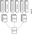
- Figure 2B shows examples of game data 34 according to a present example embodiment.
- the game data 34 may include data related to the aforementioned constructs and therefore may include object data 42, character data 46 and/or level data 44.
- An object may refer to any element or portion of an element in the game environment that can be displayed graphically in a game image frame.
- An object may include three-dimensional representations of buildings, vehicles, furniture, plants, sky, ground, ocean, sun, and/or any other suitable elements.
- the object may have other non-graphical representations such as numeric, geometric or mathematical representations.
- the object data 42 stores data relating to the current representation of the object such as the graphical representation in a game image frame or a numeric, geometric or mathematical representation.
- the object data 42 may also store attributes such as imaging data, position data, material/texture data, physical state data, visibility data, lighting data (e.g., direction, position, color and/or intensity), sound data, motion data, collision data, environment data, timer data and/or other data associated with the object.
- attributes such as imaging data, position data, material/texture data, physical state data, visibility data, lighting data (e.g., direction, position, color and/or intensity), sound data, motion data, collision data, environment data, timer data and/or other data associated with the object.
- a character is similar to an object except that the attributes are more dynamic in nature and it has additional attributes that objects typically do not have.
- certain attributes of a playing character may be controlled by the player 7.
- Certain attributes of a character that is a non-playing character (NPC) may be controlled by the game program 33.
- Examples of characters include a person, an avatar, an animal, and/or any other suitable object.
- the character may have other non-visual representations such as numeric, geometric or mathematical representations.
- a character may be associated with one or more objects such as a weapon held by a character or clothes donned by the character.
- the character data 46 stores data relating to the current representation of the character such as the graphical representation in a game image frame or a numeric, geometric or mathematical representation.
- the character data 46 may also store attributes such as imaging data, position data, material/texture data, physical state data, visibility data, lighting data (e.g., direction, position, color and/or intensity), sound data, motion data, collision data, environment data, timer data and/or other data associated with the character.
- attributes such as imaging data, position data, material/texture data, physical state data, visibility data, lighting data (e.g., direction, position, color and/or intensity), sound data, motion data, collision data, environment data, timer data and/or other data associated with the character.
- a level may refer to a specific arrangement of objects within the game environment, through which the characters must navigate.
- a level may include data regarding paths that may be traveled by characters.
- a level may also include data that encodes objectives, goals, challenges or puzzles involving the characters and the objects.
- a level has a graphical representation the can be rendered and displayed on a two-dimensional display device such as the display device 5, a level may have other non-visual representations such as numeric, geometric or mathematical representations. Also, there may be multiple levels, each with their own level data 44.
- the game data 34 may also include data relating to the current view or camera angle of the game (e.g., first-person view, third-person view, etc.) as displayed on the display device 5 which may be part of the representations and/or attributes of the object data 42, level data 44 and/or character data 46.
- data relating to the current view or camera angle of the game e.g., first-person view, third-person view, etc.
- the game data 34 may also include data relating to the current view or camera angle of the game (e.g., first-person view, third-person view, etc.) as displayed on the display device 5 which may be part of the representations and/or attributes of the object data 42, level data 44 and/or character data 46.
- the processor 10 may cause an initialization phase to occur after the player 7 has selected/started the game, causing initialization of the game.
- the initialization phase is used to carry out any necessary game setup and prepare the game data 34 for the start of the game.
- the game data 34 changes during the processing of the game program 33 (i.e., during the playing of the game) and the terminology "game state" is used herein to define the current state or properties of the game data 34 and hence the various object data 42, character data 46 and/or level data 44 and their corresponding representations and/or attributes.
- the processor 10 in execution of the game program 33 may implement one or more game loops.
- the one or more game loops run continuously during gameplay causing the game data processing function 22 and the game rendering function 24 to be routinely performed.
- a game loop may be implemented where the game data processing function 22 is performed to process the player's input via the game controller 3 and update the game state and afterwards the game rendering function 24 is performed to cause the game image to be rendered based on the updated game state for display on the display device 5.
- the game loop may also track the passage of time to control the rate of gameplay.
- parameters other than player inputs can influence the game state. For example, various timers (e.g., elapsed time, time since a particular event, virtual time of day, etc.) can have an effect on the game state. In other words, the game keeps moving even when the player 7 isn't providing input and as such the game state may be updated in the absence of the player's input.
- the number of times the game data processing function 22 is performed per second specifies the updates to the game state per second (hereinafter “updates per second”) and the number of times the game rendering function 24 is performed per second specifies game image rendering per second (hereinafter “frames per second").
- the game data processing function 22 and the game rendering function 24 would be called the same number of times per second.
- the target is 25 frames per second, it would be desirable to have the game data processing function 22 and the game rendering function 24 both being performed every 40 ms (i.e., 1 s / 25 FPS).
- both the game data processing function 22 and the game rendering function 24 would need to be performed in the 40 ms time window.
- the time of performing the game data processing function 22 and/or the game rendering function 24 may vary. If both the game data processing function 22 and the game rendering function 24 take less than 40 ms to perform, a sleep timer may be used before performing the next cycle of the game data processing function 22 and the game rendering function 24. However, if the game data processing function 22 and the game rendering function 24 take more than 40 ms to perform for a given cycle, one technique is to skip displaying of a game image to achieve a constant game speed.
- the target frames per second may be more or less than 25 frames per a second (e.g., 60 frames per second); however, it may be desired that the game data processing function 22 and the game rendering function 24 be performed not less than 20 to 25 times per second so that the human eye won't notice any lag in the rendering of the game image frames.
- the higher the frame rate the less time between images and the more powerful the processor(s) required to execute the game loop, hence the reliance on specialized processor such as GPUs.
- the game data processing function 22 and the game rendering function 24 may be executed in separate game loops and hence by independent processes.
- the game data processing function 22 may be routinely performed at a specific rate (i.e., a specific number of updates per second) regardless of when the game rendering function 24 is performed and the game rendering function 24 may be routinely performed at a specific rate (i.e., a specific number of frames per second) regardless of when the game data processing function 22 is performed.
- the player input received via the controller 3 (if any) and the game data 34 is processed. More specifically, as the player 7 plays the video game, the player 7 inputs various commands via the game controller 3 such as move left, move right, jump, shoot, to name a few examples.
- the game data processing function 22 may update the game data 34.
- the object data 42, level data 44 and/or character data 46 may be updated in response to player input via the game controller 3. It should be appreciated that not every time the game data processing function 22 is performed will there be player input via the game controller 3. Regardless of whether player input is received, the game data 34 is processed and may be updated.
- Such updating of the game data 34 may be in response to representations and/or attributes of the object data 42, level data 44 and/or character data 46, as the representations and/or attributes may specify updates to the game data 34.
- timer data may specify one or more timers (e.g., elapsed time, time since a particular event, virtual time of day, etc.), which may cause the game data 34 (e.g., the object data 42, level data 44 and/or character data 46) to be updated.
- objects not controlled by the player 7 may collide (bounce off, merge, shatter, etc.), which may cause the game data 34 e.g., the object data 42, level data 44 and/or character data 46 to be updated in response to a collision.
- the game data 34 represents data that specifies a three-dimensional (3D) graphics scene of the game.
- the process of converting a three-dimensional (3D) graphics scene, which may include one or more 3D graphics objects, into two-dimensional (2D) rasterized game image for display on the display device 5 is generally referred to as rendering.
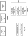
- Figure 2C illustrates an example process of converting a 3D graphics scene to a game image for display on the display device 5 via the screen.
- the game data processing function 22 processes the data that represents the three-dimensional (3D) graphics scene of the game and converts this data into a plurality of vertex data.
- the vertex data is suitable for processing by a rendering pipeline 55 (also known as a graphics pipeline).
- a rendering pipeline 55 also known as a graphics pipeline.
- the game rendering function 24 processes the vertex according to the rendering pipeline 55.
- the output of the rendering pipeline 55 is typically pixels for display on the display device 5 via the screen, step 60.
- the 3D graphics objects in the graphics scene may be subdivided into one or more 3D graphics primitives.
- a primitive may refer to a group of one or more vertices that are grouped together and/or connected to define a geometric entity (e.g., point, line, polygon, surface, object, patch, etc.) for rendering.
- vertex data is generated at this step.
- the vertex data of each primitive may include one or more attributes (e.g., position, the color, normal or texture coordinate information, etc.).
- a camera transformation e.g., rotational transformations
- vertex data may be taken into consideration.
- the vertex data derived at this step is typically an ordered list of vertices to be send to the rendering pipeline 55.
- the format of the ordered list typically depends on the specific implementation of the rendering pipeline 55.
- the game rendering function 24 processes the vertex data according to the rendering pipeline 55.
- Rendering pipelines are known in the art (e.g., OpenGl, DirectX, etc.); regardless of the specific rendering pipeline used to implement the rendering pipeline 55, the general process of the rendering pipeline 55 is to create a 2D raster representation (e.g., pixels) of a 3D scene.
- the rendering pipeline 55 in general, calculates the projected position of the vertex data into two-dimensional (2D) screen space and performs various processing which may take into consideration lighting, colour, position information, texture coordinates and/or any other suitable process to derive the game image (e.g., pixels) for output on the display 5 (step 60).
- the game apparatus 1 is distributed between a server on the internet and one or more internet appliances. Plural players may therefore participate in the same online game, and the functionality of the game program (the game rendering function and/or the game data processing function) may be executed, at least in part, by the server.
- One of the objectives of the rendering process is to compute the local (direct) illumination and global (or indirect) illumination for a point in multi-dimensional space, such as two-dimensional space or three-dimensional space, to name two non-limiting examples.
- the local illumination component may be computed in real-time.
- global (indirect) illumination there is a specular component and a diffuse component.
- specular component of the global illumination for a point the camera position is relevant, whereas to compute the diffuse component, the camera position can be ignored; what is relevant are the local surface properties of the point (i.e., its normal).
- one manner of computing the diffuse component of the global illumination relies on a weighted combination of the diffuse light picked up by multiple light probes (or simply "probes").
- Probes are locations in the multi-dimensional space where diffuse global illumination is sampled, pre-computed by the processor 10 and stored in the memory 11. Specifically, irradiance is sampled at the location of each probe in a variety of directions and this information is encoded into coefficients (hereinafter "SH coefficients") of corresponding "spherical harmonic basis functions" that can then be evaluated for an arbitrary direction.
- Spherical harmonic basis functions are an infinite series of functions, which is cut off at "bands", with the B th band adding 2B + 1 values to the series.
- the lone SH coefficient for band 0 may be considered as an ambient occlusion term and the three SH coefficients for band 1 could be considered as bent normals. Each subsequent band adds detail.
- bands are gathered by "order", where order O means the set of all bands up to O-1, so order 1 requires 1 SH coefficient, order 2 needs 4 SH coefficients, order 3 needs 9 SH coefficients (SH 00 , SH 11 , SH 10 , SH 1-1 , SH 21 , SH 2-1 , SH 2-2 , SH 20 , SH 22 ) and so on.
- Spherical harmonic basis functions Y lm with l ⁇ 0 and -l ⁇ m ⁇ l, are the analogues on the sphere to the Fourier basis on the line or circle.
- spherical harmonics are useful because they can capture the low frequency directionality of irradiance using only a few basis functions and corresponding SH coefficients.
- order 3 shown above
- spherical harmonic basis functions and SH coefficients
- the SH coefficients of the spherical harmonic basis functions encode the manner in which irradiance changes with direction (orientation). Specifically, if a certain point in the multi-dimensional space would occupy the very location of a probe, and if that point had an orientation defined by a particular normal, the diffuse global illumination present at that point could be approximated by the output of the diffuse global illumination calculation, as determined by the spherical harmonic basis functions evaluated for the particular normal, in the proportions defined by the SH coefficients.
- SH coefficients can be referred to more generally as irradiance parameters and may be placed in an array stored in the memory 11.
- the processor 10 in accordance with a non-limiting embodiment of the invention, may implement a set of processes that can be described with the aid of Fig. 3 , which illustrates an offline process 400 and a real-time process 500.
- the offline process 400 can be performed ahead of time and does not need to be performed during real-time rendering.
- the offline process 400 can include three offline sub-processes 410, 420, 430.
- the order in which the offline sub-processes are carried out is not important. Nor is it crucial that they be carried out separately from the real-time process 500, as the processor 10 may have sufficient processing power to carry out one or more of the offline sub-processes during real-time rendering.
- Sub-process 410 With reference to Fig.
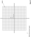
- the multi-dimensional space is subdivided into regions, e.g., according to a regular hierarchical grid (R1,1, R1,2, R1,3, ). Other subdivisions are of course possible. Each region may contain numerous points.
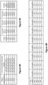
- the processor 10 For each region, the processor 10 generates a set of potentially influential probes. Specifically, for each region, the processor 10 identifies probes that may potentially, although not necessarily, have influence on the diffuse global illumination in that region, based on factors such as distance between the region and the probe, and the probe's radius (or sphere of influence). With reference to Fig. 8A , potentially influential probes may be identified by their spatial coordinates or by a code, and this information is stored in the memory 11, in association with the coordinates of the corresponding region in multi-dimensional space.
- the set of potentially influential probes is expected to include less than all of the probes in the multi-dimensional space.
- the number of potentially influential probes for a given region may vary from, say, 8 to 20. However, this does not represent a limitation of the present invention, as fewer than 8 or more than 20 probes may potentially influence the diffuse global illumination at a given region in the multi-dimensional space.
- Sub-process 420 For each probe in the multi-dimensional space, the processor 10 computes the SH coefficients, i.e., the coefficients of the spherical harmonic basis functions. This information is obtained by sampling the diffuse global illumination for multiple orientations and applying a transformation in order to determine the appropriate SH coefficients.
- SH coefficients can be based on pp. 8-9 of the article "Stupid Spherical Harmonics (SH) Tricks” by Peter-Pike Sloan, ⁇ 2008 (section entitled “Irradiance Environment Maps”), hereby incorporated by reference herein.
- the number of SH coefficients computed is a function of the order.
- the SH coefficients for a particular probe may be stored in the memory 11 as an array corresponding to identifying information for the particular probe, such as spatial coordinates or a code (see “probe codes” pr1, pr2, ..., pr4 in Fig. 8C ) which itself points to a set of spatial coordinates.
- Sub-process 430 For each probe in the multi-dimensional space, the processor 10 determines a "visibility mask". To this end, consider that there may be elements in the multi-dimensional space that provide occlusion, referred to as "occluding elements". Examples of occluding elements include walls, ceilings, floors, doors, vehicles, etc. It is expected that the irradiance at a given point in the vicinity of an occluding element would be influenced less by a probe that is hidden by such an occluding element than one that is not. Accordingly, in a non-limiting embodiment of the present invention, a set of N "occlusion planes" is defined for each probe.
- each occlusion plane may be defined by the coordinates of a point in the plane and the parameters of a normal to the plane, or by specifying the coordinates of three points in the plane. Other techniques for specifying a plane will be known to those skilled in the art.
- the visibility mask may be a binary string of P(N) bits, where the position of a bit indicates the zone and the value of the bit in that position indicates whether the zone is visible from the probe.
- N 3
- occlusion planes 701, 702, 703 for a given probe resulting in the creation of seven zones, which are ordered (the first zone being denoted 000, the second zone being denoted 001, etc.).
- the first zone being denoted 000, the second zone being denoted 001, etc.
- the visibility mask is a 7-bit number.
- the visibility mask for the given probe could be represented as the 7-bit number "1001011", where the bit in position x indicates whether zone x (the decimal equivalent to the 3-digit binary code corresponding to the zone) is visible from probe 710.
- one computationally efficient ordering scheme is to associate the zones according to their positions relative to each occlusion plane.
- the position relative to an occlusion plane could be binary, namely on the "front side" of that occlusion plane (e.g., a value of 0) or "behind” that occlusion plane (e.g., a value of 1).
- Whether or not a zone is on the "front side" of a particular occlusion plane can be determined by computing a 4D dot product of a point (x,y,z,1) within the zone with the occlusion plane represented by a 4D vector (nx, ny, nz, d).
- the sign (positive or negative) of the result indicates whether the zone is in front or behind the occlusion plane.
- N-bit number that represents the encoded number of the zone, between 0 and 2 N .
- there is actually a maximum total of 7 zones (7 ⁇ P(N) 2 3 ), meaning that there will be one 3-bit binary combination that does not represent a unique zone and does not exist. This is the case with the combination "111" in Fig. 7 , which represents a non-existent zone and, as such, the visibility mask is a 7-bit number, rather than an 8-bit number.
- the parameters corresponding to the N occlusion planes may be stored in the memory 11 as an array corresponding to identifying information, for each particular probe, such as spatial coordinates or a code which itself points to a set of spatial coordinates.
- probe 710 is associated with visibility mask "1001011".
- the occlusion planes have been defined in two-dimensional space (where they may be alternatively referred to as "occlusion axes"), they could also be defined in three-dimensional space. Analogously, the zones created by the occlusion axes or planes may consequently be defined in two-dimensional or three-dimensional space, respectively.
- the real-time process 500 may then be executed by the processor 10 for each point to be rendered.
- the real-time process may be performed for each point in a scene to be rendered, once per frame.
- the term "real-time” is used merely to distinguish this process from the offline process 400 but this does not necessarily require that the real-time process 500 be performed in real time, although it may be.
- the real-time process 500 is now described with reference to a set of steps shown in Fig. 5 . The existence of an order in the below description does not imply that the order must be followed, as some steps may be performed in a different order.
- Step 510 The processor 10 selects a point in the scene to be rendered.
- Step 515 The processor 10 determines the region (e.g., according to the grid as in Fig.
- Step 520 The processor 10 initializes the SH coefficients to zero.
- Step 530 The processor 10 consults the set of potentially influential probes for the region (which may have been pre-calculated as a result of the offline sub-process 430; see also Fig. 8A ) and a first probe from the set is selected (the "selected probe").
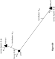
- Step 540 The processor 10 determines a weight for the selected probe (as it relates to the selected point). The weight could be based in part on relative proximity (distance) to the selected point. The weight could also be such that the weight for the selected probe is not proportional to its distance to the selected point, compared to other probes in the set.
- Step 550 The processor 10 now determines the zone to which the point belongs, based on the occlusion planes for the selected probe. It is recalled that there are N occlusion planes and P(N) zones per probe. As such, a binary tree method may be used. Accordingly, for example, the processor 10 consults the memory 11 and a first occlusion plane for the selected probe is selected. The processor 10 determines whether or not the selected point is on the "front side" of the selected occlusion plane for the selected probe.
- the sign (positive or negative) of the result indicates which of two sub-sets of zones the selected point is located in (i.e., in front or behind).
- This operation is then performed for the remaining N-1 occlusion planes for the selected probe, resulting in the identification of one of P(N) zones to which the selected point belongs.
- the zone to which the selected zone belongs is encoded as a binary string of P(N) bits, where only one of the bit positions is a 1 (corresponding to the zone containing the selected point) and the rest are 0.
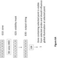
- Step 560 The processor 10 conducts a "visibility test” in order to determine whether the selected probe should have influence on the diffuse global illumination at the selected point. Specifically, this step determines whether the zone to which the selected point belongs is visible from the selected probe. If the zone is visible by the selected probe, the probe can be referred to as a "sighted" probe, which is in contrast to a blind probe that would not be capable of "seeing" the zone. In a non-limiting embodiment, with reference to Figs.
- the binary string produced at the output of step 530 (which has a 1 in the position corresponding to the zone containing the selected point and 0's elsewhere), denoted 610, is compared with the binary string that represents the visibility mask for the selected probe computed by sub-process 420 (which has 1's in the positions corresponding to the zones that are visible from the selected probe), denoted 620.
- the comparison between binary strings 610 and 620 can be a bit-wise logical "AND", resulting in a binary output string 630, that will either retain a 1 in the position corresponding to the zone to which the selected point belongs (which, as seen in Fig.
- Step 570 The processor 10 adds each of the SH coefficients for the selected point to the respective previously stored values of the SH coefficients (which will be zero on the first pass through the real-time process 500).
- the processor 10 also performs weighting, according to the weight corresponding to the selected probe (see step 540).
- order 3 spherical harmonic basis functions may be used, which implies that there are 9 spherical harmonic basis functions and therefore 9 SH coefficients for each color space channel. Thus, for the RGB color space, there would be a total of 27 SH coefficients.
- the YCgCo or YCbCr color space is used, where Y is the luminance and Cg and Co are the chrominance.
- Step 580 The processor 10 verifies whether there are any remaining probes on the set of potentially influential probes for the selected point. If yes, the processor 10 selects the next probe on the set and returns to step 540. If not, the processor 10 proceeds to step 590. Step 590: The processor 10 now has a final "blended" value for each of the various SH coefficients (SH 00 ', SH 11 ', ..., SH 22 '), which takes into account the weight of each probe.
- the intensity of the diffuse global illumination at the selected point is calculated by evaluating the spherical harmonic basis function for the normal at the selected point and adding the results scaled by the corresponding blended SH coefficients to yield a sum; and (ii) normalizing the sum by dividing it by the sum of the weights of the probes used in the calculation (see step 570).
- the intensity of the diffuse global illumination at the selected point having a normal ( ⁇ , ⁇ ) is equal to: (SH 00 '*Y 00 ( ⁇ , ⁇ )) + (SH 11 '*Y 11 ( ⁇ , ⁇ )) + ...
- the intensity of the diffuse global illumination at the selected point is stored and used elsewhere in the rendering process.
- the processor 10 selects a next point and returns to step 520.
- SH coefficients are a specific non-limiting example of irradiance parameters and that computing a linear combination of the SH parameters and spherical harmonic basis functions evaluated at a normal associated with the selected point is a non-limiting example of a mapping function of irradiance parameters that can be used to determine the diffuse global illumination component.
- embodiments of the present invention may be useful in a variety of applications, such as computer games, civilian and military simulation environments, virtual reality, computer-aided animation and cinematography, and the like.
- computation of the diffuse global illumination in accordance with certain embodiments may allow the more efficient use of computational resources due to the use of probes, and further due to the use of zones created by occlusion planes or axes, while still obtaining realistic lighting that emulates the effects of occluding objects in the scene geometry.
Landscapes
- Engineering & Computer Science (AREA)
- Multimedia (AREA)
- Physics & Mathematics (AREA)
- General Physics & Mathematics (AREA)
- Computer Graphics (AREA)
- Theoretical Computer Science (AREA)
- Human Computer Interaction (AREA)
- Spectroscopy & Molecular Physics (AREA)
- Image Generation (AREA)
- Processing Or Creating Images (AREA)
Claims (15)
- Computerimplementiertes Verfahren zum Bestimmen einer Beleuchtungskomponente für einen ausgewählten Punkt in einem mehrdimensionalen Raum einer Computergrafik-Szene, wobei das Verfahren Folgendes umfasst:- Identifizieren eines Satzes von Fühlern, die dem ausgewählten Punkt zugeordnet sind, wobei sich die Fühler in dem mehrdimensionalen Raum befinden und jeder Fühler in dem Satz von Fühlern einen potentiellen Einfluss auf die diffuse globale Beleuchtung für den ausgewählten Punkt hat;- Bestimmen für jeden ausgewählten Fühler, welche von mehreren Zonen für den ausgewählten Fühler den ausgewählten Punkt enthält, und Bestimmen der Sichtbarkeit der bestimmten Zone für den ausgewählten Fühler, wobei die Zonen für jeden ausgewählten Fühler durch Schnitte von im Voraus definierten Okklusionsebenen für den ausgewählten Fühler definiert sind, und- Ableiten einer Beleuchtungskomponente an dem ausgewählten Punkt durch Kombinieren von Szenenbestrahlungsdaten, die denjenigen der Fühler zugeordnet sind, für die bestimmt wird, dass die ihnen entsprechende bestimmte Zone für sie sichtbar ist.
- Computerimplementiertes Verfahren nach Anspruch 1, wobei das Bestimmen, welche von mehreren Zonen für den ausgewählten Fühler den ausgewählten Punkt enthält, das Ausführen einer Operation umfasst, die den ausgewählten Punkt und jede von mehreren im Voraus definierten Okklusionsebenen für den ausgewählten Fühler einbezieht, um ein Endergebnis zu erhalten, das die bestimmte Zone angibt.
- Computerimplementiertes Verfahren nach Anspruch 1, wobei das Bestimmen der Sichtbarkeit der bestimmten Zone für den ausgewählten Fühler das Anwenden einer Sichtbarkeitsmaske, die dem ausgewählten Fühler zugeordnet ist, umfasst.
- Computerimplementiertes Verfahren nach Anspruch 3, wobei die Sichtbarkeit, die dem ausgewählten Fühler zugeordnet ist, die eine oder die mehreren Zonen, die für den ausgewählten Fühler sichtbar sind, oder die Tatsache, dass für den ausgewählten Fühler keine Zone sichtbar ist, codiert.
- Computerimplementiertes Verfahren nach Anspruch 4, wobei die bestimmte Zone durch einen Code codiert wird und wobei das Anwenden einer Sichtbarkeitsmaske, die dem ausgewählten Fühler zugeordnet ist, das Ausführen eines Vergleichs zwischen dem Code und der Sichtbarkeitsmaske, die dem ausgewählten Fühler zugeordnet ist, umfasst.
- Computerimplementiertes Verfahren nach Anspruch 1, wobei das Kombinieren von Szenenbestrahlungsdaten, die denjenigen der Fühler zugeordnet sind, für die bestimmt wird, dass die ihnen entsprechende bestimmte Zone für sie sichtbar ist, im Folgenden gesichteter Fühler genannt, (i) das Bestimmen von Bestrahlungsdaten für jeden gesichteten Fühler, (ii) das Bestimmen eines Gewichts jedes gesichteten Fühlers; und (iii) das Berechnen einer gewichteten Summe der Bestrahlungsdaten für jeden gesichteten Fühler umfasst.
- Computerimplementiertes Verfahren nach Anspruch 6, wobei das Identifizieren eines Satzes von Fühlern, die dem ausgewählten Punkt zugeordnet sind, das Bestimmen eines Bereichs, in dem sich der ausgewählte Punkt befindet, und das Identifizieren eines Satzes von Fühlern, die dem Bereich zugeordnet sind, umfasst und wobei für den ausgewählten Punkt die Anzahl von Fühlern in dem Satz größer als die Anzahl gesichteter Fühler ist.
- Computerimplementiertes Verfahren nach Anspruch 1, wobei das Kombinieren von Szenenbestrahlungsdaten, die denjenigen der Fühler zugeordnet sind, für die bestimmt wird, dass die ihnen entsprechende bestimmte Zone für sie sichtbar ist, im Folgenden gesichteter Fühler genannt, (i) das Bestimmen einer Matrix von Bestrahlungsparametern für jeden gesichteten Fühler, (ii) das Bestimmen eines Gewichts jedes gesichteten Fühlers; (iii) für jedes Element der Matrix das Berechnen einer gewichteten Summe des entsprechenden Bestrahlungsparameters über die gesichteten Fühler hinweg, um einen entsprechenden gemischten Bestrahlungsparameter zu ergeben; und (iv) das Berechnen einer Abbildungsfunktion der gemischten Bestrahlungsparameter, um dadurch die Beleuchtungskomponente zu bestimmen, umfasst.
- Computerimplementiertes Verfahren nach Anspruch 8, wobei die Bestrahlungsparameter sphärische harmonische Koeffizienten sind und wobei die Abbildungsfunktion eine Linearkombination der sphärischen harmonischen Parameter und von sphärischen harmonischen Basisfunktionen, die bei einer dem ausgewählten Punkt zugeordneten Normalen ausgewertet werden, enthält.
- Computerimplementiertes Verfahren nach Anspruch 1, wobei das Kombinieren von Szenenbestrahlungsdaten, die denjenigen der Fühler zugeordnet sind, für die bestimmt wird, dass die ihnen entsprechende bestimmte Zone für sie sichtbar ist, im Folgenden gesichteter Fühler genannt, (i) das Bestimmen einer Matrix von Bestrahlungsparametern für jeden von wenigstens zwei gesichteten Fühlern, (ii) das Bestimmen einer Beleuchtungskomponente für jeden der gesichteten Fühler durch Berechnen einer Abbildungsfunktion der gemischten Bestrahlungsparameter für diesen gesichteten Fühler, (iii) das Bestimmen eines Gewichts jedes der gesichteten Fühler, und (iv) das Berechnen einer gewichteten Summe der Beleuchtungskomponenten für die gesichteten Fühler, um dadurch die Beleuchtungskomponente zu bestimmen, umfasst.
- Computerimplementiertes Verfahren nach Anspruch 1, wobei die Beleuchtungskomponente eine erste Beleuchtungskomponente ist, die ein Teil einer globalen Beleuchtungskomponente ist, wobei das Verfahren ferner Folgendes umfasst:- Ableiten einer lokalen Beleuchtungskomponente; und- Rendern des ausgewählten Punkts auf einer Anzeigevorrichtung basierend auf einer Kombination der lokalen und der globalen Beleuchtungskomponente.
- Computerimplementiertes Verfahren nach Anspruch 11, wobei das Rendern in Echtzeit ausgeführt wird.
- System zum Bestimmen einer Beleuchtungskomponente für einen ausgewählten Punkt in einem mehrdimensionalen Raum einer Computergrafik-Szene, wobei das System Folgendes umfasst:- einen Prozessor, und- einen Speicher, der Informationen speichert, die mehrere Fühler in dem mehrdimensionalen Raum und ihnen zugeordnete Informationen identifizieren;- wobei der Prozessor konfiguriert ist zum:• Identifizieren eines Satzes von Fühlern, die dem ausgewählten Punkt zugeordnet sind, wobei sich die Fühler in dem mehrdimensionalen Raum befinden und jeder Fühler in dem Satz von Fühlern einen potentiellen Einfluss auf die diffuse globale Beleuchtung für den ausgewählten Punkt hat;• Bestimmen für jeden ausgewählten Fühler, welche von mehreren Zonen für den ausgewählten Fühler den ausgewählten Punkt enthält, und Bestimmen der Sichtbarkeit der bestimmten Zone für den ausgewählten Fühler, wobei die Zonen für jeden ausgewählten Fühler durch Schnitte von im Voraus definierten Okklusionsebenen für den ausgewählten Fühler definiert sind, und• Ableiten einer Beleuchtungskomponente an dem ausgewählten Punkt durch Kombinieren von Szenenbestrahlungsdaten, die denjenigen Fühlern zugeordnet sind, für die bestimmt wird, dass die ihnen entsprechende bestimmte Zone für sie sichtbar ist.
- Computerlesbares Medium, das computerlesbare Anweisungen enthält, die dann, wenn sie durch eine Rechenvorrichtung ausgeführt werden, die Rechenvorrichtung veranlassen, das Verfahren zum Bestimmen einer Beleuchtungskomponente für einen ausgewählten Punkt in einem mehrdimensionalen Raum einer Computergrafik-Szene auszuführen, wobei das Verfahren Folgendes umfasst:- Identifizieren eines Satzes von Fühlern, die dem ausgewählten Punkt zugeordnet sind, wobei sich die Fühler in dem mehrdimensionalen Raum befinden und jeder Fühler in dem Satz von Fühlern einen potentiellen Einfluss auf die diffuse globale Beleuchtung für den ausgewählten Punkt hat;- Bestimmen für jeden ausgewählten Fühler, welche von mehreren Zonen für den ausgewählten Fühler den ausgewählten Punkt enthält, und Bestimmen der Sichtbarkeit der bestimmten Zone für den ausgewählten Fühler, wobei die Zonen für jeden ausgewählten Fühler durch Schnitte von im Voraus definierten Okklusionsebenen für den ausgewählten Fühler definiert sind, und- Ableiten einer Beleuchtungskomponente an dem ausgewählten Punkt durch Kombinieren von Szenenbestrahlungsdaten, die denjenigen Fühlern zugeordnet sind, für die bestimmt wird, dass die ihnen entsprechende bestimmte Zone für sie sichtbar ist.
- Spielvorrichtung, die Folgendes umfasst:- eine Eingabe/Ausgabe-Schnittstelle, die einem Anwender erlaubt, Spieleingaben zu steuern und Spielausgaben wahrzunehmen;- einen Speicher, der (i) Informationen, die mehrere Zonen in einem mehrdimensionalen Raum einer Computergrafik-Szene entsprechenden Sätzen von Fühlern in dem mehrdimensionalen Raum zuordnen, wobei j eder Fühler in einem Satz von Fühlern einen potentiellen Einfluss auf die diffuse globale Beleuchtung für einen ausgewählten Punkt hat und wobei die Zonen durch Schnitte von im Voraus definierten Okklusionsebenen definiert sind, und (ii) ausführbare Anweisungen speichert,- einen Prozessor, der konfiguriert ist zum Ausführen ausführbarer Anweisungen, um eine Beleuchtungskomponente an jedem von mehreren ausgewählten Punkten in dem mehrdimensionalen Raum aus Szenenbestrahlungsdaten abzuleiten, die jedem von einem oder mehreren Fühlern, für die eine den ausgewählten Punkt enthaltende Zone sichtbar ist, zugeordnet sind, wobei der eine oder die mehreren Fühler aus dem Satz von Fühlern, der der Zone entspricht, ausgewählt werden.
Applications Claiming Priority (1)
| Application Number | Priority Date | Filing Date | Title |
|---|---|---|---|
| CA2944435A CA2944435C (en) | 2016-10-04 | 2016-10-04 | Methods, systems and computer-readable media for diffuse global illumination using probes |
Publications (3)
| Publication Number | Publication Date |
|---|---|
| EP3306569A1 EP3306569A1 (de) | 2018-04-11 |
| EP3306569A9 EP3306569A9 (de) | 2018-07-18 |
| EP3306569B1 true EP3306569B1 (de) | 2024-05-01 |
Family
ID=57867970
Family Applications (1)
| Application Number | Title | Priority Date | Filing Date |
|---|---|---|---|
| EP16204196.6A Active EP3306569B1 (de) | 2016-10-04 | 2016-12-14 | Verfahren, systeme und computerlesbare medien für diffuse globale beleuchtung mit sonden |
Country Status (4)
| Country | Link |
|---|---|
| US (1) | US10137372B2 (de) |
| EP (1) | EP3306569B1 (de) |
| JP (1) | JP6970508B2 (de) |
| CA (1) | CA2944435C (de) |
Families Citing this family (15)
| Publication number | Priority date | Publication date | Assignee | Title |
|---|---|---|---|---|
| US10455779B2 (en) * | 2017-07-24 | 2019-10-29 | Osram Sylvania Inc. | Irradiance-controlled fixture for horticultural applications |
| US11605198B2 (en) * | 2018-06-29 | 2023-03-14 | Baobab Studios Inc. | Systems and methods for generating dynamic real-time high-quality lighting for digital animation |
| GB2579603A (en) * | 2018-12-05 | 2020-07-01 | Sony Interactive Entertainment Inc | Method and system for generating a recording of video game gameplay |
| JP6698929B1 (ja) * | 2019-10-31 | 2020-05-27 | 株式会社Cygames | プログラム、ゲーム仮想空間提供方法、及びゲーム仮想空間提供装置 |
| CN111744183B (zh) * | 2020-07-02 | 2024-02-09 | 网易(杭州)网络有限公司 | 游戏中的光照采样方法、装置以及计算机设备 |
| CN113827967B (zh) * | 2021-09-24 | 2024-08-13 | 网易(杭州)网络有限公司 | 游戏控制方法及装置、电子设备、存储介质 |
| CN116800984A (zh) * | 2022-03-15 | 2023-09-22 | 华为技术有限公司 | 编解码方法和装置 |
| CN116797710A (zh) * | 2022-03-15 | 2023-09-22 | 华为技术有限公司 | 编码方法及电子设备 |
| CN116797711A (zh) * | 2022-03-15 | 2023-09-22 | 华为技术有限公司 | 解码方法及电子设备 |
| CN116934947A (zh) * | 2022-04-02 | 2023-10-24 | 腾讯科技(深圳)有限公司 | 虚拟模型的光照渲染方法、装置和存储介质及电子设备 |
| CN116934946A (zh) * | 2022-04-02 | 2023-10-24 | 腾讯科技(深圳)有限公司 | 虚拟地形的光照渲染方法、装置和存储介质及电子设备 |
| US20240226741A9 (en) * | 2022-10-19 | 2024-07-11 | Nintendo Co., Ltd. | Storage medium, information processing system, information processing device, and game processing method |
| CN116485984B (zh) * | 2023-06-25 | 2024-05-31 | 深圳元戎启行科技有限公司 | 全景影像车辆模型全局光照模拟方法、装置、设备及介质 |
| US20250104329A1 (en) * | 2023-09-27 | 2025-03-27 | Nvidia Corporation | Neural components for differentiable ray tracing of radio propagation |
| CN117745926B (zh) * | 2023-11-29 | 2025-03-14 | 上海暖叠网络科技有限公司 | 一种全局光照渲染方法 |
Family Cites Families (5)
| Publication number | Priority date | Publication date | Assignee | Title |
|---|---|---|---|---|
| US6628298B1 (en) | 1998-07-17 | 2003-09-30 | The Regents Of The University Of California | Apparatus and method for rendering synthetic objects into real scenes using measurements of scene illumination |
| US7212206B2 (en) | 2003-08-20 | 2007-05-01 | Sony Computer Entertainment Inc. | Method and apparatus for self shadowing and self interreflection light capture |
| US20090309877A1 (en) | 2008-06-16 | 2009-12-17 | Microsoft Corporation | Soft shadow rendering |
| US10008034B2 (en) | 2013-05-03 | 2018-06-26 | Nvidia Corporation | System, method, and computer program product for computing indirect lighting in a cloud network |
| GB2571656B (en) * | 2015-03-03 | 2019-11-27 | Imagination Tech Ltd | Graphics rendering using directional representations of lighting at probe positions within a scene |
-
2016
- 2016-10-04 CA CA2944435A patent/CA2944435C/en active Active
- 2016-12-13 US US15/377,913 patent/US10137372B2/en active Active
- 2016-12-14 EP EP16204196.6A patent/EP3306569B1/de active Active
-
2017
- 2017-01-26 JP JP2017012385A patent/JP6970508B2/ja active Active
Also Published As
| Publication number | Publication date |
|---|---|
| CA2944435A1 (en) | 2018-04-04 |
| JP6970508B2 (ja) | 2021-11-24 |
| US10137372B2 (en) | 2018-11-27 |
| JP2018060499A (ja) | 2018-04-12 |
| US20180093183A1 (en) | 2018-04-05 |
| EP3306569A9 (de) | 2018-07-18 |
| EP3306569A1 (de) | 2018-04-11 |
| CA2944435C (en) | 2024-01-09 |
Similar Documents
| Publication | Publication Date | Title |
|---|---|---|
| US10137372B2 (en) | Virtual scene lighting with light probe culling based upon visibility | |
| US8648864B2 (en) | System and method for blended animation enabling an animated character to aim at any arbitrary point in a virtual space | |
| US11638874B2 (en) | Systems and methods for changing a state of a game object in a video game | |
| CA2968587C (en) | System and method for determining curved path of travel for a character in cover mode in a game environment | |
| US20100020080A1 (en) | Image generation system, image generation method, and information storage medium | |
| JP6960317B2 (ja) | ビデオゲーム画像レンダリング方法及びシステム | |
| CA2968589C (en) | System and method for placing a character animation at a location in a game environment | |
| US10628970B2 (en) | System and method for determining a color value of a pixel | |
| EP3381524B1 (de) | Steuerung der fortbewegung mehrerer nicht-spieler-character in einem simulierten mehrdimensionalen weltraum | |
| JP7830290B2 (ja) | ゲームシステム、サーバ装置、プログラム及びゲーム提供方法 | |
| US6890261B2 (en) | Game system, program and image generation method | |
| US11501496B2 (en) | Navigation system and method using a bounding volume hierarchy | |
| EP3254741B1 (de) | System und verfahren zur bestimmung einer gekrümmten bewegungsbahn für eine spielfigur im cover-modus in einer spielumgebung | |
| EP3254742A1 (de) | System und verfahren zur platzierung einer zeichenanimation an einem ort in einer spielumgebung | |
| US20250128164A1 (en) | System for rendering skin tone within a game application environment | |
| JP2002216151A (ja) | 画像生成システム、プログラム及び情報記憶媒体 | |
| JP2007164323A (ja) | プログラム、情報記憶媒体及び画像生成システム | |
| Abi Chakra | Priority based level of detail approach for interpolated animations of articulated models |
Legal Events
| Date | Code | Title | Description |
|---|---|---|---|
| PUAI | Public reference made under article 153(3) epc to a published international application that has entered the european phase |
Free format text: ORIGINAL CODE: 0009012 |
|
| STAA | Information on the status of an ep patent application or granted ep patent |
Free format text: STATUS: THE APPLICATION HAS BEEN PUBLISHED |
|
| AK | Designated contracting states |
Kind code of ref document: A1 Designated state(s): AL AT BE BG CH CY CZ DE DK EE ES FI FR GB GR HR HU IE IS IT LI LT LU LV MC MK MT NL NO PL PT RO RS SE SI SK SM TR |
|
| AX | Request for extension of the european patent |
Extension state: BA ME |
|
| STAA | Information on the status of an ep patent application or granted ep patent |
Free format text: STATUS: REQUEST FOR EXAMINATION WAS MADE |
|
| 17P | Request for examination filed |
Effective date: 20181010 |
|
| RBV | Designated contracting states (corrected) |
Designated state(s): AL AT BE BG CH CY CZ DE DK EE ES FI FR GB GR HR HU IE IS IT LI LT LU LV MC MK MT NL NO PL PT RO RS SE SI SK SM TR |
|
| STAA | Information on the status of an ep patent application or granted ep patent |
Free format text: STATUS: EXAMINATION IS IN PROGRESS |
|
| 17Q | First examination report despatched |
Effective date: 20210406 |
|
| GRAP | Despatch of communication of intention to grant a patent |
Free format text: ORIGINAL CODE: EPIDOSNIGR1 |
|
| STAA | Information on the status of an ep patent application or granted ep patent |
Free format text: STATUS: GRANT OF PATENT IS INTENDED |
|
| INTG | Intention to grant announced |
Effective date: 20231212 |
|
| GRAS | Grant fee paid |
Free format text: ORIGINAL CODE: EPIDOSNIGR3 |
|
| GRAA | (expected) grant |
Free format text: ORIGINAL CODE: 0009210 |
|
| STAA | Information on the status of an ep patent application or granted ep patent |
Free format text: STATUS: THE PATENT HAS BEEN GRANTED |
|
| AK | Designated contracting states |
Kind code of ref document: B1 Designated state(s): AL AT BE BG CH CY CZ DE DK EE ES FI FR GB GR HR HU IE IS IT LI LT LU LV MC MK MT NL NO PL PT RO RS SE SI SK SM TR |
|
| REG | Reference to a national code |
Ref country code: GB Ref legal event code: FG4D |
|
| REG | Reference to a national code |
Ref country code: CH Ref legal event code: EP |
|
| REG | Reference to a national code |
Ref country code: DE Ref legal event code: R096 Ref document number: 602016087249 Country of ref document: DE |
|
| REG | Reference to a national code |
Ref country code: IE Ref legal event code: FG4D |
|
| REG | Reference to a national code |
Ref country code: LT Ref legal event code: MG9D |
|
| REG | Reference to a national code |
Ref country code: NL Ref legal event code: MP Effective date: 20240501 |
|
| PG25 | Lapsed in a contracting state [announced via postgrant information from national office to epo] |
Ref country code: IS Free format text: LAPSE BECAUSE OF FAILURE TO SUBMIT A TRANSLATION OF THE DESCRIPTION OR TO PAY THE FEE WITHIN THE PRESCRIBED TIME-LIMIT Effective date: 20240901 |
|
| PG25 | Lapsed in a contracting state [announced via postgrant information from national office to epo] |
Ref country code: BG Free format text: LAPSE BECAUSE OF FAILURE TO SUBMIT A TRANSLATION OF THE DESCRIPTION OR TO PAY THE FEE WITHIN THE PRESCRIBED TIME-LIMIT Effective date: 20240501 |
|
| PG25 | Lapsed in a contracting state [announced via postgrant information from national office to epo] |
Ref country code: FI Free format text: LAPSE BECAUSE OF FAILURE TO SUBMIT A TRANSLATION OF THE DESCRIPTION OR TO PAY THE FEE WITHIN THE PRESCRIBED TIME-LIMIT Effective date: 20240501 Ref country code: HR Free format text: LAPSE BECAUSE OF FAILURE TO SUBMIT A TRANSLATION OF THE DESCRIPTION OR TO PAY THE FEE WITHIN THE PRESCRIBED TIME-LIMIT Effective date: 20240501 |
|
| PG25 | Lapsed in a contracting state [announced via postgrant information from national office to epo] |
Ref country code: GR Free format text: LAPSE BECAUSE OF FAILURE TO SUBMIT A TRANSLATION OF THE DESCRIPTION OR TO PAY THE FEE WITHIN THE PRESCRIBED TIME-LIMIT Effective date: 20240802 |
|
| PG25 | Lapsed in a contracting state [announced via postgrant information from national office to epo] |
Ref country code: PT Free format text: LAPSE BECAUSE OF FAILURE TO SUBMIT A TRANSLATION OF THE DESCRIPTION OR TO PAY THE FEE WITHIN THE PRESCRIBED TIME-LIMIT Effective date: 20240902 |
|
| REG | Reference to a national code |
Ref country code: AT Ref legal event code: MK05 Ref document number: 1683449 Country of ref document: AT Kind code of ref document: T Effective date: 20240501 |
|
| PG25 | Lapsed in a contracting state [announced via postgrant information from national office to epo] |
Ref country code: NL Free format text: LAPSE BECAUSE OF FAILURE TO SUBMIT A TRANSLATION OF THE DESCRIPTION OR TO PAY THE FEE WITHIN THE PRESCRIBED TIME-LIMIT Effective date: 20240501 |
|
| PG25 | Lapsed in a contracting state [announced via postgrant information from national office to epo] |
Ref country code: ES Free format text: LAPSE BECAUSE OF FAILURE TO SUBMIT A TRANSLATION OF THE DESCRIPTION OR TO PAY THE FEE WITHIN THE PRESCRIBED TIME-LIMIT Effective date: 20240501 |
|
| PG25 | Lapsed in a contracting state [announced via postgrant information from national office to epo] |
Ref country code: AT Free format text: LAPSE BECAUSE OF FAILURE TO SUBMIT A TRANSLATION OF THE DESCRIPTION OR TO PAY THE FEE WITHIN THE PRESCRIBED TIME-LIMIT Effective date: 20240501 |
|
| PG25 | Lapsed in a contracting state [announced via postgrant information from national office to epo] |
Ref country code: PL Free format text: LAPSE BECAUSE OF FAILURE TO SUBMIT A TRANSLATION OF THE DESCRIPTION OR TO PAY THE FEE WITHIN THE PRESCRIBED TIME-LIMIT Effective date: 20240501 |
|
| PG25 | Lapsed in a contracting state [announced via postgrant information from national office to epo] |
Ref country code: LV Free format text: LAPSE BECAUSE OF FAILURE TO SUBMIT A TRANSLATION OF THE DESCRIPTION OR TO PAY THE FEE WITHIN THE PRESCRIBED TIME-LIMIT Effective date: 20240501 |
|
| PG25 | Lapsed in a contracting state [announced via postgrant information from national office to epo] |
Ref country code: PT Free format text: LAPSE BECAUSE OF FAILURE TO SUBMIT A TRANSLATION OF THE DESCRIPTION OR TO PAY THE FEE WITHIN THE PRESCRIBED TIME-LIMIT Effective date: 20240902 Ref country code: PL Free format text: LAPSE BECAUSE OF FAILURE TO SUBMIT A TRANSLATION OF THE DESCRIPTION OR TO PAY THE FEE WITHIN THE PRESCRIBED TIME-LIMIT Effective date: 20240501 Ref country code: NO Free format text: LAPSE BECAUSE OF FAILURE TO SUBMIT A TRANSLATION OF THE DESCRIPTION OR TO PAY THE FEE WITHIN THE PRESCRIBED TIME-LIMIT Effective date: 20240801 Ref country code: NL Free format text: LAPSE BECAUSE OF FAILURE TO SUBMIT A TRANSLATION OF THE DESCRIPTION OR TO PAY THE FEE WITHIN THE PRESCRIBED TIME-LIMIT Effective date: 20240501 Ref country code: LV Free format text: LAPSE BECAUSE OF FAILURE TO SUBMIT A TRANSLATION OF THE DESCRIPTION OR TO PAY THE FEE WITHIN THE PRESCRIBED TIME-LIMIT Effective date: 20240501 Ref country code: IS Free format text: LAPSE BECAUSE OF FAILURE TO SUBMIT A TRANSLATION OF THE DESCRIPTION OR TO PAY THE FEE WITHIN THE PRESCRIBED TIME-LIMIT Effective date: 20240901 Ref country code: HR Free format text: LAPSE BECAUSE OF FAILURE TO SUBMIT A TRANSLATION OF THE DESCRIPTION OR TO PAY THE FEE WITHIN THE PRESCRIBED TIME-LIMIT Effective date: 20240501 Ref country code: GR Free format text: LAPSE BECAUSE OF FAILURE TO SUBMIT A TRANSLATION OF THE DESCRIPTION OR TO PAY THE FEE WITHIN THE PRESCRIBED TIME-LIMIT Effective date: 20240802 Ref country code: FI Free format text: LAPSE BECAUSE OF FAILURE TO SUBMIT A TRANSLATION OF THE DESCRIPTION OR TO PAY THE FEE WITHIN THE PRESCRIBED TIME-LIMIT Effective date: 20240501 Ref country code: ES Free format text: LAPSE BECAUSE OF FAILURE TO SUBMIT A TRANSLATION OF THE DESCRIPTION OR TO PAY THE FEE WITHIN THE PRESCRIBED TIME-LIMIT Effective date: 20240501 Ref country code: BG Free format text: LAPSE BECAUSE OF FAILURE TO SUBMIT A TRANSLATION OF THE DESCRIPTION OR TO PAY THE FEE WITHIN THE PRESCRIBED TIME-LIMIT Effective date: 20240501 Ref country code: AT Free format text: LAPSE BECAUSE OF FAILURE TO SUBMIT A TRANSLATION OF THE DESCRIPTION OR TO PAY THE FEE WITHIN THE PRESCRIBED TIME-LIMIT Effective date: 20240501 Ref country code: RS Free format text: LAPSE BECAUSE OF FAILURE TO SUBMIT A TRANSLATION OF THE DESCRIPTION OR TO PAY THE FEE WITHIN THE PRESCRIBED TIME-LIMIT Effective date: 20240801 |
|
| PG25 | Lapsed in a contracting state [announced via postgrant information from national office to epo] |
Ref country code: DK Free format text: LAPSE BECAUSE OF FAILURE TO SUBMIT A TRANSLATION OF THE DESCRIPTION OR TO PAY THE FEE WITHIN THE PRESCRIBED TIME-LIMIT Effective date: 20240501 |
|
| PG25 | Lapsed in a contracting state [announced via postgrant information from national office to epo] |
Ref country code: EE Free format text: LAPSE BECAUSE OF FAILURE TO SUBMIT A TRANSLATION OF THE DESCRIPTION OR TO PAY THE FEE WITHIN THE PRESCRIBED TIME-LIMIT Effective date: 20240501 |
|
| PG25 | Lapsed in a contracting state [announced via postgrant information from national office to epo] |
Ref country code: CZ Free format text: LAPSE BECAUSE OF FAILURE TO SUBMIT A TRANSLATION OF THE DESCRIPTION OR TO PAY THE FEE WITHIN THE PRESCRIBED TIME-LIMIT Effective date: 20240501 |
|
| PG25 | Lapsed in a contracting state [announced via postgrant information from national office to epo] |
Ref country code: RO Free format text: LAPSE BECAUSE OF FAILURE TO SUBMIT A TRANSLATION OF THE DESCRIPTION OR TO PAY THE FEE WITHIN THE PRESCRIBED TIME-LIMIT Effective date: 20240501 Ref country code: SK Free format text: LAPSE BECAUSE OF FAILURE TO SUBMIT A TRANSLATION OF THE DESCRIPTION OR TO PAY THE FEE WITHIN THE PRESCRIBED TIME-LIMIT Effective date: 20240501 |
|
| PG25 | Lapsed in a contracting state [announced via postgrant information from national office to epo] |
Ref country code: SM Free format text: LAPSE BECAUSE OF FAILURE TO SUBMIT A TRANSLATION OF THE DESCRIPTION OR TO PAY THE FEE WITHIN THE PRESCRIBED TIME-LIMIT Effective date: 20240501 |
|
| PG25 | Lapsed in a contracting state [announced via postgrant information from national office to epo] |
Ref country code: SM Free format text: LAPSE BECAUSE OF FAILURE TO SUBMIT A TRANSLATION OF THE DESCRIPTION OR TO PAY THE FEE WITHIN THE PRESCRIBED TIME-LIMIT Effective date: 20240501 Ref country code: SK Free format text: LAPSE BECAUSE OF FAILURE TO SUBMIT A TRANSLATION OF THE DESCRIPTION OR TO PAY THE FEE WITHIN THE PRESCRIBED TIME-LIMIT Effective date: 20240501 Ref country code: RO Free format text: LAPSE BECAUSE OF FAILURE TO SUBMIT A TRANSLATION OF THE DESCRIPTION OR TO PAY THE FEE WITHIN THE PRESCRIBED TIME-LIMIT Effective date: 20240501 Ref country code: EE Free format text: LAPSE BECAUSE OF FAILURE TO SUBMIT A TRANSLATION OF THE DESCRIPTION OR TO PAY THE FEE WITHIN THE PRESCRIBED TIME-LIMIT Effective date: 20240501 Ref country code: DK Free format text: LAPSE BECAUSE OF FAILURE TO SUBMIT A TRANSLATION OF THE DESCRIPTION OR TO PAY THE FEE WITHIN THE PRESCRIBED TIME-LIMIT Effective date: 20240501 Ref country code: CZ Free format text: LAPSE BECAUSE OF FAILURE TO SUBMIT A TRANSLATION OF THE DESCRIPTION OR TO PAY THE FEE WITHIN THE PRESCRIBED TIME-LIMIT Effective date: 20240501 |
|
| REG | Reference to a national code |
Ref country code: DE Ref legal event code: R097 Ref document number: 602016087249 Country of ref document: DE |
|
| PG25 | Lapsed in a contracting state [announced via postgrant information from national office to epo] |
Ref country code: IT Free format text: LAPSE BECAUSE OF FAILURE TO SUBMIT A TRANSLATION OF THE DESCRIPTION OR TO PAY THE FEE WITHIN THE PRESCRIBED TIME-LIMIT Effective date: 20240501 |
|
| PLBE | No opposition filed within time limit |
Free format text: ORIGINAL CODE: 0009261 |
|
| STAA | Information on the status of an ep patent application or granted ep patent |
Free format text: STATUS: NO OPPOSITION FILED WITHIN TIME LIMIT |
|
| 26N | No opposition filed |
Effective date: 20250204 |
|
| PG25 | Lapsed in a contracting state [announced via postgrant information from national office to epo] |
Ref country code: SI Free format text: LAPSE BECAUSE OF FAILURE TO SUBMIT A TRANSLATION OF THE DESCRIPTION OR TO PAY THE FEE WITHIN THE PRESCRIBED TIME-LIMIT Effective date: 20240501 |
|
| PG25 | Lapsed in a contracting state [announced via postgrant information from national office to epo] |
Ref country code: MC Free format text: LAPSE BECAUSE OF FAILURE TO SUBMIT A TRANSLATION OF THE DESCRIPTION OR TO PAY THE FEE WITHIN THE PRESCRIBED TIME-LIMIT Effective date: 20240501 |
|
| REG | Reference to a national code |
Ref country code: CH Ref legal event code: PL |
|
| PG25 | Lapsed in a contracting state [announced via postgrant information from national office to epo] |
Ref country code: LU Free format text: LAPSE BECAUSE OF NON-PAYMENT OF DUE FEES Effective date: 20241214 |
|
| PG25 | Lapsed in a contracting state [announced via postgrant information from national office to epo] |
Ref country code: SE Free format text: LAPSE BECAUSE OF FAILURE TO SUBMIT A TRANSLATION OF THE DESCRIPTION OR TO PAY THE FEE WITHIN THE PRESCRIBED TIME-LIMIT Effective date: 20240501 |
|
| REG | Reference to a national code |
Ref country code: BE Ref legal event code: MM Effective date: 20241231 |
|
| PG25 | Lapsed in a contracting state [announced via postgrant information from national office to epo] |
Ref country code: BE Free format text: LAPSE BECAUSE OF NON-PAYMENT OF DUE FEES Effective date: 20241231 |
|
| PG25 | Lapsed in a contracting state [announced via postgrant information from national office to epo] |
Ref country code: CH Free format text: LAPSE BECAUSE OF NON-PAYMENT OF DUE FEES Effective date: 20241231 |
|
| PG25 | Lapsed in a contracting state [announced via postgrant information from national office to epo] |
Ref country code: IE Free format text: LAPSE BECAUSE OF NON-PAYMENT OF DUE FEES Effective date: 20241214 |
|
| PGFP | Annual fee paid to national office [announced via postgrant information from national office to epo] |
Ref country code: DE Payment date: 20251211 Year of fee payment: 10 |
|
| PGFP | Annual fee paid to national office [announced via postgrant information from national office to epo] |
Ref country code: GB Payment date: 20251219 Year of fee payment: 10 |
|
| PGFP | Annual fee paid to national office [announced via postgrant information from national office to epo] |
Ref country code: FR Payment date: 20251229 Year of fee payment: 10 |