EP3306432B1 - Flight control method for an aircraft, control device and computer program to implement the flight control method - Google Patents
Flight control method for an aircraft, control device and computer program to implement the flight control method Download PDFInfo
- Publication number
- EP3306432B1 EP3306432B1 EP16799373.2A EP16799373A EP3306432B1 EP 3306432 B1 EP3306432 B1 EP 3306432B1 EP 16799373 A EP16799373 A EP 16799373A EP 3306432 B1 EP3306432 B1 EP 3306432B1
- Authority
- EP
- European Patent Office
- Prior art keywords
- aircraft
- flight
- signal
- control device
- control instruction
- Prior art date
- Legal status (The legal status is an assumption and is not a legal conclusion. Google has not performed a legal analysis and makes no representation as to the accuracy of the status listed.)
- Active
Links
Images




Classifications
-
- G—PHYSICS
- G05—CONTROLLING; REGULATING
- G05D—SYSTEMS FOR CONTROLLING OR REGULATING NON-ELECTRIC VARIABLES
- G05D1/00—Control of position, course, altitude or attitude of land, water, air or space vehicles, e.g. using automatic pilots
- G05D1/02—Control of position or course in two dimensions
-
- G—PHYSICS
- G05—CONTROLLING; REGULATING
- G05D—SYSTEMS FOR CONTROLLING OR REGULATING NON-ELECTRIC VARIABLES
- G05D1/00—Control of position, course, altitude or attitude of land, water, air or space vehicles, e.g. using automatic pilots
- G05D1/0011—Control of position, course, altitude or attitude of land, water, air or space vehicles, e.g. using automatic pilots associated with a remote control arrangement
- G05D1/0033—Control of position, course, altitude or attitude of land, water, air or space vehicles, e.g. using automatic pilots associated with a remote control arrangement by having the operator tracking the vehicle either by direct line of sight or via one or more cameras located remotely from the vehicle
-
- G—PHYSICS
- G05—CONTROLLING; REGULATING
- G05D—SYSTEMS FOR CONTROLLING OR REGULATING NON-ELECTRIC VARIABLES
- G05D1/00—Control of position, course, altitude or attitude of land, water, air or space vehicles, e.g. using automatic pilots
- G05D1/40—Control within particular dimensions
- G05D1/46—Control of position or course in three dimensions [3D]
-
- B—PERFORMING OPERATIONS; TRANSPORTING
- B64—AIRCRAFT; AVIATION; COSMONAUTICS
- B64C—AEROPLANES; HELICOPTERS
- B64C39/00—Aircraft not otherwise provided for
- B64C39/02—Aircraft not otherwise provided for characterised by special use
- B64C39/024—Aircraft not otherwise provided for characterised by special use of the remote controlled vehicle type, i.e. RPV
-
- G—PHYSICS
- G05—CONTROLLING; REGULATING
- G05D—SYSTEMS FOR CONTROLLING OR REGULATING NON-ELECTRIC VARIABLES
- G05D1/00—Control of position, course, altitude or attitude of land, water, air or space vehicles, e.g. using automatic pilots
- G05D1/0011—Control of position, course, altitude or attitude of land, water, air or space vehicles, e.g. using automatic pilots associated with a remote control arrangement
-
- G—PHYSICS
- G05—CONTROLLING; REGULATING
- G05D—SYSTEMS FOR CONTROLLING OR REGULATING NON-ELECTRIC VARIABLES
- G05D1/00—Control of position, course, altitude or attitude of land, water, air or space vehicles, e.g. using automatic pilots
- G05D1/0011—Control of position, course, altitude or attitude of land, water, air or space vehicles, e.g. using automatic pilots associated with a remote control arrangement
- G05D1/0016—Control of position, course, altitude or attitude of land, water, air or space vehicles, e.g. using automatic pilots associated with a remote control arrangement characterised by the operator's input device
-
- G—PHYSICS
- G05—CONTROLLING; REGULATING
- G05D—SYSTEMS FOR CONTROLLING OR REGULATING NON-ELECTRIC VARIABLES
- G05D1/00—Control of position, course, altitude or attitude of land, water, air or space vehicles, e.g. using automatic pilots
- G05D1/20—Control system inputs
- G05D1/22—Command input arrangements
- G05D1/221—Remote-control arrangements
-
- B—PERFORMING OPERATIONS; TRANSPORTING
- B64—AIRCRAFT; AVIATION; COSMONAUTICS
- B64U—UNMANNED AERIAL VEHICLES [UAV]; EQUIPMENT THEREFOR
- B64U2101/00—UAVs specially adapted for particular uses or applications
- B64U2101/30—UAVs specially adapted for particular uses or applications for imaging, photography or videography
-
- B—PERFORMING OPERATIONS; TRANSPORTING
- B64—AIRCRAFT; AVIATION; COSMONAUTICS
- B64U—UNMANNED AERIAL VEHICLES [UAV]; EQUIPMENT THEREFOR
- B64U2201/00—UAVs characterised by their flight controls
- B64U2201/10—UAVs characterised by their flight controls autonomous, i.e. by navigating independently from ground or air stations, e.g. by using inertial navigation systems [INS]
-
- B—PERFORMING OPERATIONS; TRANSPORTING
- B64—AIRCRAFT; AVIATION; COSMONAUTICS
- B64U—UNMANNED AERIAL VEHICLES [UAV]; EQUIPMENT THEREFOR
- B64U2201/00—UAVs characterised by their flight controls
- B64U2201/20—Remote controls
-
- G—PHYSICS
- G05—CONTROLLING; REGULATING
- G05D—SYSTEMS FOR CONTROLLING OR REGULATING NON-ELECTRIC VARIABLES
- G05D2109/00—Types of controlled vehicles
- G05D2109/20—Aircraft, e.g. drones
Definitions
- the embodiments of the present disclosure generally relate to the technical field of aircraft control, and more particularly, to a flight control method and apparatus, and an electronic device.
- Aircraft can be used in many fields, such as aerial photography, transportation of articles and the like, and have the characteristics of low cost, small size, high flexibility and the like.
- a user can control the flight of the aircraft so as to reach a desired flight target.
- European patent application publication EP 2 818 958 A2 discloses a flying vehicle guiding system including a remotely controllable flying vehicle system, a surveying instrument able to measure distance, angle and track, and a ground base station for controlling flight of the flying vehicle system based on measuring results by the surveying instrument.
- European patent application publication EP 2 511 781 A1 discloses a method and system for controlling an unmanned aircraft.
- the system has an evaluation unit determining an actual state of an automotive unmanned controllable aerial vehicle in a coordinate system, where the actual state is utilized for determining a position, an orientation and/or a position change of the vehicle.
- a control unit controls the aerial vehicle and produces control data using an algorithm depending on the determined actual state and a defined reference state.
- the control unit automatically changes the aerial vehicle in the reference state in a defined tolerance range in a controlled manner using the control data.
- the present disclosure provides a flight control method and apparatus and an electronic device, in accordance with claims which follow.
- a flight control method as defined by claim 1.
- the method comprises determining a relative position relationship between an aircraft and a control device, the control device being a single device configured to control the aircraft; determining a polar coordinate system with the control device as an origin according to the relative position relationship; receiving a flight direction control instruction sent by the control device, the flight direction control instruction being generated on the basis of the polar coordinate system.
- the method further comprises controlling, according to coordinate information about the aircraft in the polar coordinate system, the aircraft to fly in accordance with the flight direction control instruction.
- Controlling the aircraft to fly in accordance with the flight direction control instruction comprises, when the flight direction control instruction refers to forward flight or backward flight, controlling the aircraft to fly along a direction of a connecting line between the aircraft and the control device so that a length value in the coordinate information varies and an angle value does not vary; or when the flight direction control instruction refers to left turn or right turn, controlling the aircraft to fly along a direction perpendicular to a connecting line between the aircraft and the control device so that an angle value in the coordinate information varies and a length value does not vary.
- the method further includes that determining the relative position relationship between the aircraft and the control device comprises: sensing a sensing signal transmitted by a signal transceiver device at the control device respectively via a plurality of signal sensing devices installed at different positions on the aircraft; comparing signal strengths sensed respectively by the signal sensing devices, wherein projections, of a signal sensing device corresponding to a highest signal strength, a signal sensing device corresponding to a lowest signal strength and the control device, to a vertical direction are located on a same straight line, and the signal sensing device corresponding to the highest signal strength and the control device are adjacent nodes on the straight line; and determining the relative position relationship according to installation positions of the signal sensing devices on the aircraft; or sending detection signals to a signal transceiver device at the control device simultaneously via a plurality of signal transmitting devices installed at different positions on the aircraft; determining a detection signal first received by the signal transceiver device and a detection signal last received by the signal transceiver device according to a received response message returned by the signal trans
- a flight control apparatus as defined in claim 6, including: a relationship determination unit configured to determine a relative position relationship between an aircraft and a control device, the control device being a single device configured to control the aircraft; a coordinate system determination unit configured to determine a polar coordinate system with the control device as an origin according to the relative position relationship; a receiving unit configured to receive a flight direction control instruction sent by the control device, the flight direction control instruction being generated on the basis of the polar coordinate system; and a drive unit configured to control, according to coordinate information about the aircraft in the polar coordinate system, the aircraft to fly in accordance with the flight direction control instruction.
- the drive unit may include: a first drive sub-unit configured to, when the flight direction control instruction refers to forward flight or backward flight, control the aircraft to fly along a direction of a connecting line between the aircraft and the control device so that a length value in the coordinate information varies and an angle value does not vary.
- the drive unit may include: a second drive sub-unit configured to, when the flight direction control instruction refers to left turn or right turn, drive the aircraft to fly along a direction perpendicular to a connecting line between the aircraft and the control device so that an angle value in the coordinate information varies and a length value does not vary.
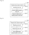
- the relationship determination unit may include: a sensing sub-unit configured to sense a sensing signal transmitted by a signal transceiver device at the control device respectively via a plurality of signal sensing devices installed at different positions on the aircraft; a comparison sub-unit configured to compare signal strengths sensed respectively by the signal sensing devices, wherein projection, of a signal sensing device corresponding to a highest signal strength, a signal sensing device corresponding to a lowest signal strength and the control device, to a vertical direction, are located on a same straight line, and the signal sensing device corresponding to the highest signal strength and the control device are adjacent nodes on the straight line; and a first relationship determination sub-unit configured to determine the relative position relationship according to installation positions of the signal sensing devices on the aircraft.
- the relationship determination unit may include: a sending sub-unit configured to send detection signals to a signal transceiver device at the control device simultaneously via a plurality of signal transmitting devices installed at different positions on the aircraft; a device determination sub-unit configured to determine a detection signal first received by the signal transceiver device and a detection signal last received by the signal transceiver device according to a received response message returned by the signal transceiver device, projections of signal transmitting devices corresponding to the detection signals and the control device, to a vertical direction, being located on a same straight line, and a signal transmitting device corresponding to the first received detection signal and the control device being adjacent nodes on the straight line; and a second relationship determination sub-unit configured to determine the relative position relationship according to installation positions of the signal transmitting devices on the aircraft.
- the relationship determination unit may include: a reading sub-unit configured to read first positioning information about the aircraft via a first positioning device installed on the aircraft; a receiving sub-unit configured to receive second positioning information sent by a signal transceiver device at the control device, the second positioning information being generated by a second positioning device at the control device; and a third relationship determination sub-unit configured to determine the relative position relationship according to the first positioning information and the second positioning information.
- the apparatus may further include: a reading unit configured to read a type identifier contained in the flight direction control instruction; and a determination unit configured to determine the type of the flight direction control instruction according to the type identifier, wherein when the type identifier has a first value, it is indicated that the flight direction control instruction is generated on the basis of the polar coordinate system; and when the type identifier has a second value, it is indicated that the flight direction control instruction is generated on the basis of a flight coordinate system of the aircraft, then the drive unit directly executes the flight direction control instruction so as to drive the aircraft.
- the drive unit may include: a transformation sub-unit configured to transform a target direction corresponding to the flight direction control instruction from the polar coordinate system to a flight coordinate system of the aircraft; and a fourth drive sub-unit configured to drive the aircraft in accordance with the transformed target direction.
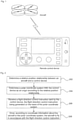
- Fig. 1 is a schematic diagram illustrating a flight control scenario according to an exemplary embodiment.
- signal transmission is implemented in a wireless manner between a remote control device and an aircraft. After a user sends a control instruction to the aircraft via the remote control device, the aircraft can be controlled to fly.
- flight control is required to be implemented from a perspective of the aircraft.
- flight direction control instruction refers to leftward flight
- the aircraft turns to the left side of the aircraft itself.
- the user often cannot distinguish real-time attitudes of the aircraft, thereby making it difficult to implement control from a perspective of the aircraft.
- Fig. 2 is a flow chart showing a flight control method according to an exemplary embodiment.
- Step 202 a relative position relationship between an aircraft and a control device is determined.
- the aircraft may acquire the relative position relationship in accordance with a preset period; or as another exemplary implementation, the aircraft may acquire the relative position relationship whenever receiving a flight direction control instruction.
- Step 204 a polar coordinate system with the control device as an origin is determined according to the relative position relationship.
- Step 206 a flight direction control instruction sent by the control device is received, the flight direction control instruction being generated on the basis of the polar coordinate system.
- control device sends data such as the flight direction control instruction and other types of instructions or information to the aircraft via a signal transceiver device, and the signal transceiver device may be built in a remote control device.
- Data transmission may be implemented between the aircraft and the remote control device in any wireless manner such as Wi-Fi or Bluetooth, and there are no limits specifically made in the embodiment of the disclosure.
- flight control for the aircraft is implemented, actually, by taking the control device as a center without needing to consider a real-time attitude (such as orientation) of the aircraft, and the aircraft may be self-adjusted according to a target direction corresponding to the flight direction control instruction.
- Step 208 according to coordinate information about the aircraft in the polar coordinate system, the aircraft is driven to fly in accordance with the flight direction control instruction.
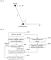
- the control device is located at a point O, and a polar coordinate system OX with the point O as an origin is established.
- the aircraft may get coordinate information about the aircraft itself in the polar coordinate system OX according to the relative position relationship between the aircraft itself and the control device. It is assumed that the aircraft is located at a point A and coordinate information is ( ⁇ , ⁇ ), then the control device need not consider, for flight control of the aircraft, factors such as the real-time attitude of the aircraft, and may send a flight direction control instruction in a self-centered manner instead, and the aircraft only needs to transform the flight direction control instruction into adjustment of the coordinate information about the aircraft itself. For instance, as an exemplary implementation, the aircraft may complete flying by transforming a target direction corresponding to the flight direction control instruction from the polar coordinate system to a flight coordinate system of the aircraft itself and then executing the transformed target direction.
- the flight direction control instruction is configured to control a flight direction of the aircraft, including a forward direction, a backward direction, a leftward direction and a rightward direction in a plane, and excluding an upward direction and a downward direction in a three-dimensional space.
- the embodiments of the present disclosure enable a user to perform control directly according to his/her own control target without transformation of control targets from a perspective of an aircraft, thereby greatly reducing the difficulty in controlling the aircraft.
- Fig. 4 is another flow chart showing a flight control method according to an exemplary embodiment. As shown in Fig. 4 , the method may include the steps as follows.
- Step 402 an aircraft is started to fly.
- Step 404 the aircraft receives a flight direction control instruction sent by a control device.
- signal transmission and reception between the control device and the aircraft may be implemented via a remote control device.
- the remote control device may be a dedicated aircraft remote control or may be implemented by an APP installed on a smart device such as a smart phone and a smart tablet computer, wherein, wireless signals may be transmitted and received between the remote control device and the aircraft by means of Wi-Fi, Bluetooth and the like.
- Step 406 a corresponding instruction type is identified by reading of a value of a type identifier in the flight direction control instruction.
- the type identifier has a first value, it is indicated that a target direction is obtained on the basis of a polar coordinate system, and it is necessary to proceed to Step 408.
- the type identifier has a second value, it is indicated that the target direction is obtained on the basis of a flight coordinate system of the aircraft, and it is necessary to proceed to Step 410.
- the control device serves as an origin of the polar coordinate system
- the aircraft serves as an origin of the flight coordinate system.
- the control device sends a flight direction control instruction on the basis of the polar coordinate system
- a corresponding target direction is obtained on the basis of the polar coordinate system, thereby facilitating the implementation of effective flight control by the user when it is difficult to distinguish flight attitudes of the aircraft (particularly, a four-axis aircraft).
- the aircraft is required to transform the corresponding target direction to one in its flight coordinate system so that a flight task can be smoothly fulfilled by the aircraft.
- a corresponding target direction is obtained on the basis of the flight coordinate system, that is, the user sends the flight direction control instruction from a perspective of the aircraft, and the aircraft may directly execute the corresponding flight direction control instruction so as to smoothly fulfill the flight task.
- a corresponding format changeover switch may be provided on the remote control device so that the user sends a required type of flight direction control instruction via the switch.
- a format of a control instruction may be set in advance, and one or more data bits in the control instruction serve as a type identifier, which can thereby present a control mode for the user. It is assumed that a type identifier includes two data bits, the target direction in the flight direction control instruction is obtained on the basis of the polar coordinate system when the type identifier is '00' namely a first value, and the target direction in the flight direction control instruction is obtained on the basis of the flight coordinate system when the type identifier is '01' namely a second value.
- Step 404' signal transmission and reception operations are executed between the aircraft and the control device.
- Step 406' the aircraft determines the relative position relationship between the aircraft and the control device according to signal transmission and reception conditions.
- the relative position relationship between the aircraft and the control device is determined by Step 404'-406', wherein there is no constraint on the sequence of Steps 404'-406' and Steps 404-406.
- the aircraft may execute Steps 404'-406' in accordance with a preset mode, for instance, the aircraft may execute Steps 404'-406' in accordance with a preset period or may execute Steps 404'-406' after receiving the flight direction control instruction.
- the relative position relationship between the aircraft and the control device may be determined on the basis of signal transmission and reception between the aircraft and the control device (namely the remote control device). Some modes for determining the relative position relationship are illustrated below on the basis of the above signal transmission and reception modes.
- a sensing signal transmitted by a signal transceiver device at a control device is sensed respectively via a plurality of signal sensing devices installed at different positions on an aircraft.
- Signal strengths sensed respectively by the signal sensing devices are compared, wherein projections of a signal sensing device corresponding to a highest signal strength, a signal sensing device corresponding to a lowest signal strength and the control device, to a vertical direction, are located on a same straight line, and the signal sensing device corresponding to the highest signal strength and the control device are adjacent nodes on the straight line.
- a relative position relationship is determined according to installation positions of the signal sensing devices on the aircraft. As shown in Fig.
- a user takes a smart phone as a remote control device so as to implement remote control of an aircraft.
- the smart phone is configured with a signal transceiver device for any wireless signal, and a sensing signal is sent via the signal transceiver device.
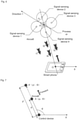
- a plurality of signal sensing devices is provided at different positions on the aircraft. For instance, in a four-axis aircraft shown in Fig. 5 , a signal sensing device 1, a signal sensing device 2, a signal sensing device 3, a signal sensing device 4 and the like are provided respectively.
- Each signal sensing device senses the above sensing signal, and informs a processor on the aircraft of a sensed signal strength, and the processor compares the signal strengths to obtain a signal sensing device corresponding to a highest signal strength and a signal sensing device corresponding to a lowest signal strength.
- the signal strength sensed by the signal sensing device 4 is highest and the signal strength sensed by the signal sensing device 2 is lowest, it is considered that projections of the control device (namely the remote control device such as the smart phone in Fig. 5 ), the signal sensing device 4 and the signal sensing device 2 to the vertical direction are located on a same straight line.
- the aircraft may assume that the orientation of the control device is a certain fixed direction, and a polar coordinate system may be determined accordingly, for instance, the polar coordinate system OX shown in Fig. 5 .
- ⁇ is a distance of OA
- ⁇ is a distance of OA
- ⁇ is a distance of OA
- ⁇ is a distance of OA
- ⁇ may be calculated according to sensed signal strengths by the signal sensing device 4 and the signal sensing device 2 (for instance, correspondences between the sensed signal strengths and the distances are stored in advance).
- a relative distance mode may be adopted.
- a point A recorded at a certain moment serves as an origin, so a subsequent distance variation adopts a relative distance variation with respect to the point A.
- ⁇ is an included angle between OA and OX, and may be obtained by calculation after the orientation of a polar axis (namely an X axis) of the polar coordinate system OX is determined.
- a current attitude of the aircraft and a deviation angle ⁇ between a direction 1 that the aircraft is facing and a line OA may be obtained on the basis of a coordinate position of the point A in the polar coordinate system OX, so in a flight drive process of the aircraft, the deviation angle ⁇ can be taken into consideration, and it is unnecessary for the control device to get a real-time attitude of the aircraft.
- detection signals are sent to a signal transceiver device at a control device simultaneously via a plurality of signal transmitting devices installed at different positions on the aircraft; a detection signal first received by the signal transceiver device and a detection signal last received by the signal transceiver device are determined according to a received response message returned by the signal transceiver device, wherein projections of signal transmitting devices corresponding to the detection signals and the control device to a vertical direction are located on a same straight line, and a signal transmitting device corresponding to the first received detection signal and the control device are adjacent nodes on the straight line.
- a relative position relationship is determined according to installation positions of the signal transmitting devices on the aircraft.
- a signal transmitting device 1, a signal transmitting device 2, a signal transmitting device 3, a signal transmitting device 4 and the like are provided at different positions on an aircraft, a signal transceiver device is provided at a control device (namely a smart phone), and the signal transceiver device may receive a detection signal sent by each signal transmitting device on the aircraft.
- a control device namely a smart phone
- each signal detection device may be contained in the corresponding transmitted detection signal, so the smart phone may distinguish and record a receiving sequence of the corresponding detection signal of each signal transmitting device.
- the signal transmitting device 1, the signal transmitting device 2, the signal transmitting device 3 and the signal transmitting device 4 correspond to receiving time t1, receiving time t2, receiving time t3 and receiving time t4, t4 is minimum and t2 is maximum
- projections of the control device namely a remote control device such as the smart phone in Fig. 6
- the signal transmitting device 4 and the signal transmitting device 2 to a vertical direction, are located on a same straight line.
- a determination mode for a relative position relationship is similar to the embodiment shown in Fig. 5 , which will not be elaborated herein.
- positioning devices such as Global Positioning System (GPS) chips and Beidou positioning chips
- GPS Global Positioning System
- Beidou positioning chips may be installed on an aircraft and a remote control device of a control device respectively, so as to be configured to obtain positioning information (such as longitude and latitude information) about the aircraft and about the remote control device respectively.
- a relative position relationship therebetween may be calculated by sharing of positioning information between the aircraft and the remote control device.
- the aircraft transforms a target direction in the flight direction control instruction according to the relative position relationship between the aircraft and the control device.
- the instruction is executed to drive the aircraft to fly towards the target direction.
- the aircraft in the case of proceeding to Step 406, the aircraft directly executes the received flight direction control instruction; and in the case of proceeding to Step 408, the aircraft needs to transform the target direction in the received flight direction control instruction and performs drive control in accordance with the transformed target direction.
- the aircraft may be controlled by flight control modes corresponding to different target directions.
- the aircraft is driven to fly along a direction of a connecting line between the aircraft and a control device so that a length value in coordinate information varies and an angle value does not vary.
- Fig. 7 it is assumed that the control device is located at a point O, and a polar coordinate system OX with the point O as an origin is established.
- the aircraft is located at a point A and the coordinate information is ( ⁇ , ⁇ ), and it is indicated that the length of a segment OA is ⁇ , and an included angle between OX and OA is ⁇ .
- the aircraft When the flight direction control instruction sent by the control device refers to forward flight, the aircraft shall fly along an extension direction of a line OA by means of power adjustment and allocation for each drive component (such as drive motors on four axes of a four-axis aircraft). It is assumed that the aircraft flies to a point A' and its coordinate information is changed to ( ⁇ ', ⁇ ).In the above process, the control device does not need to focus on a real-time attitude of the aircraft at the point A. For instance, the orientation of the aircraft may not be an OA direction, but the aircraft can self-adjust its real-time attitude and flight direction on the basis of the relative position relationship between the aircraft itself and the control device and the coordinate information about the point A, thereby smoothly flying to point A'. Similarly, when the flight direction control instruction refers to backward flight, the aircraft shall make ⁇ decreased and ⁇ unvaried, that is, the aircraft shall fly along a direction of a line AO.
- each drive component such as drive motors on four axes of a
- the aircraft is driven to fly along a direction perpendicular to a connecting line between the aircraft and a control device so that an angle value in coordinate information varies and a length value does not vary.
- Fig. 8 it is assumed that the control device is located at a point O, and a polar coordinate system OX with the point O as an origin is established.
- the aircraft is located at a point A and the coordinate information is ( ⁇ , ⁇ ), and it is indicated that the length of a segment OA is ⁇ , and an included angle between the OX and the OA is ⁇ .
- the aircraft When the flight direction control instruction sent by the control device refers to left turn, the aircraft shall always fly along a direction perpendicular to a connecting line between the aircraft itself and the point O by means of power adjustment and allocation for each drive component (such as drive motors on four axes of a four-axis aircraft).
- the aircraft flies along a circular arc with the point O serving as the centre of a circle and the OA serving as a radius, and the orientation of the aircraft in a flight process is tangent to the circular arc.
- the aircraft flies from the point A to a point A" and the coordinate information is changed to ( ⁇ , ⁇ ').
- a flight route and control process of the aircraft completely take the point O where the control device is located as the center, thereby facilitating the simplification of the flight control process of the control device.
- the aircraft shall make ⁇ unvaried and ⁇ decreased, that is, the aircraft shall fly along a right tangential direction of the OA.
- the flight direction control instruction refers to oblique flight
- a straight component and a rotational component contained in the flight direction control instruction are extracted, the straight component corresponding to forward flight or backward flight of the aircraft, and the rotational component corresponding to left turn or right turn of the flight.
- the aircraft is driven according to the straight component and the rotational component so that a length value in coordinate information varies in accordance with the straight component and an angle value varies in accordance with the rotational component.
- Fig. 9 it is assumed that the control device is located at a point O, and a polar coordinate system OX with point O as an origin is established.
- the aircraft is located at a point A and the coordinate information is ( ⁇ , ⁇ ), and it is indicated that the length of a segment OA is ⁇ , and an included angle between the OX and the OA is ⁇ .
- An oblique direction refers to a direction, which is not a pure forward-backward direction or leftward-rightward direction, but contains components of both the forward-backward direction and the leftward-rightward direction.
- the aircraft shall be controlled to fly by decomposing the oblique direction into the forward-backward direction (namely the straight component) and the leftward-rightward direction (namely the rotational component).
- the aircraft is located at a point A ( ⁇ , ⁇ ), and on the basis of a target direction of the flight direction control instruction, the straight component obtained by decomposition needs to be used to adjust p, the rotational component obtained by decomposition needs to be used to adjust ⁇ , and adjusted ⁇ " and ⁇ " are obtained respectively, that is, a point B ( ⁇ ", ⁇ ") is taken as a flight target.
- the embodiments of the present disclosure also provide a flight control apparatus.
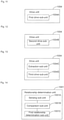
- Fig. 10 is a block diagram of a flight control apparatus according to an exemplary embodiment.
- the apparatus includes a relationship determination unit 1001, a coordinate system determination unit 1002, a receiving unit 1003 and a drive unit 1004, in which:the relationship determination unit 1001 is configured to determine a relative position relationship between an aircraft and a control device; the coordinate system determination unit 1002 is configured to determine a polar coordinate system with the control device as an origin according to the relative position relationship; the receiving unit 1003 is configured to receive a flight direction control instruction sent by the control device, the flight direction control instruction being generated on the basis of the polar coordinate system; and the drive unit 1004 is configured to drive, according to coordinate information about the aircraft in the polar coordinate system, the aircraft to fly in accordance with the flight direction control instruction.
- the drive unit 1004 may include: a first drive sub-unit 1004A.
- the first drive sub-unit 1004A is configured to, when the flight direction control instruction refers to forward flight or backward flight, drive the aircraft to fly along a direction of a connecting line between the aircraft and the control device so that a length value in the coordinate information varies and an angle value does not vary.
- the drive unit 1004 may include: a second drive sub-unit 1004B.
- the second drive sub-unit 1004B is configured to, when the flight direction control instruction refers to left turn or right turn, drive the aircraft to fly along a direction perpendicular to a connecting line between the aircraft and the control device so that an angle value in the coordinate information varies and a length value does not vary.
- the drive unit 1004 may include: an extraction sub-unit 1004C and a third drive sub-unit 1004D, in which: the extraction sub-unit 1004C is configured to, when the flight direction control instruction refers to oblique flight, extract a straight component and a rotational component contained in the flight direction control instruction, the straight component corresponding to forward flight or backward flight of the aircraft, and the rotational component corresponding to left turn or right turn of the flight; and the third drive sub-unit 1004D is configured to drive the aircraft according to the straight component and the rotational component so that a length value in the coordinate information varies in accordance with the straight component and an angle value varies in accordance with the rotational component.
- the relationship determination unit 1001 may include: a sensing sub-unit 1001A, a comparison sub-unit 1001B and a first relationship determination sub-unit 1001C, in which: the sensing sub-unit 1001A is configured to sense a sensing signal transmitted by a signal transceiver device at the control device respectively via a plurality of signal sensing devices installed at different positions on the aircraft; the comparison sub-unit 1001B is configured to compare signal strengths respectively sensed by the signal sensing devices, wherein projections of a signal sensing device corresponding to a highest signal strength, a signal sensing device corresponding to a lowest signal strength and the control device, to the vertical direction, are located on a same straight line, and the signal sensing device corresponding to the highest signal strength and the control device are adjacent nodes on the straight line; and the first relationship determination sub-unit 1001
- sensing sub-unit 1001A the comparison sub-unit 1001B and the first relationship determination sub-unit 1001C in the above apparatus embodiment shown in Fig. 14 may also be contained in the above apparatus embodiments shown in Figs. 11-13 , and there are no limits specifically made in the embodiment of the disclosure.
- the relationship determination unit 1001 may include: a sensing sub-unit 1001D, a device determination sub-unit 1001E and a second relationship determination sub-unit 1001F, in which: the sending sub-unit 1001D is configured to send detection signals to a signal transceiver device at the control device simultaneously via a plurality of signal transmitting devices installed at different positions on the aircraft; the device determination sub-unit 1001E is configured to determine a detection signal first received by the signal transceiver device and a detection signal last received by the signal transceiver device according to a received response message returned by the signal transceiver device, herein projections of the signal transmitting devices corresponding to the detection signals and the control device to a vertical direction are located on a same straight line, and a signal transmitting device corresponding to the first received detection signal and the control device are adjacent nodes on
- sensing sub-unit 1001D the device determination sub-unit 1001E and the second relationship determination sub-unit 1001F in the above apparatus embodiment shown in Fig. 15 may also be contained in the above apparatus embodiments shown in Figs. 11-13 , and there are no limits specifically made in the embodiment of the disclosure.
- the relationship determination unit 1001 may include: a reading sub-unit 1001G, a receiving sub-unit 1001H and a third relationship determination sub-unit 1001I, in which: the reading sub-unit 1001G is configured to read first positioning information about the aircraft via a first positioning device installed on the aircraft; the receiving sub-unit 1001H is configured to receive second positioning information sent by a signal transceiver device at the control device, the second positioning information being generated by a second positioning device at the control device; and the third relationship determination sub-unit 1001I is configured to determine the relative position relationship according to the first positioning information and the second positioning information.
- the apparatus may further include: a reading unit 1006 and a determination unit 1005, in which: the reading unit 1006 is configured to read a type identifier contained in the flight direction control instruction; and the determination unit 1005 is configured to determine the type of the flight direction control instruction according to the type identifier, herein when the type identifier has a first value, it is indicated that the flight direction control instruction is generated on the basis of the polar coordinate system; and when the type identifier has a second value, it is indicated that the flight direction control instruction is generated on the basis of a flight coordinate system of the aircraft, then the drive unit 1004 directly executes the flight direction control instruction so as to drive the aircraft.
- the reading unit 1006 is configured to read a type identifier contained in the flight direction control instruction
- the determination unit 1005 is configured to determine the type of the flight direction control instruction according to the type identifier, herein when the type identifier has a first value, it is indicated that the flight direction control instruction is generated on the basis of the polar coordinate system; and when the type
- the drive unit 1004 may include: a transformation sub-unit 1004E and a fourth drive sub-unit 1004F; in which: the transformation sub-unit 1004E is configured to transform a target direction corresponding to the flight direction control instruction from the polar coordinate system to a flight coordinate system of the aircraft; and the fourth drive sub-unit 1004F is configured to drive the aircraft in accordance with the transformed target direction.
- apparatus embodiments substantially correspond to the method embodiments, please refer to description of the method embodiments for more detailed description.
- the apparatus embodiments described above are merely schematic.
- the units illustrated as separate components may be or may not be physically separated.
- Components for unit display may be or may not be physical units. That is, the components may be located at a place or may be distributed on a plurality of network units.
- the purposes of the solutions in the embodiments of the present disclosure may be fulfilled by selecting some or all modules according to actual requirements. Those skilled in the art may understand and implement the solutions without creative work.
- the embodiments of the present disclosure also provide a flight control apparatus, which includes: a processor; and a memory configured to store instructions executable by the processor, in which the processor is configured to: determine a relative position relationship between an aircraft and a control device; determine a polar coordinate system with the control device as an origin according to the relative position relationship; receive a flight direction control instruction sent by the control device, the flight direction control instruction being generated on the basis of the polar coordinate system; and drive, according to coordinate information about the aircraft in the polar coordinate system, the aircraft to fly in accordance with the flight direction control instruction.
- the embodiments of the present disclosure also provide a terminal, which includes a memory and one or more programs, wherein the one or more programs are stored in the memory and executed by one or more processors, the one or more programs include instructions configured to perform the following operations: determining a relative position relationship between an aircraft and a control device; determining a polar coordinate system with the control device as an origin according to the relative position relationship; receiving a flight direction control instruction sent by the control device, the flight direction control instruction being generated on the basis of the polar coordinate system; and driving, according to coordinate information about the aircraft in the polar coordinate system, the aircraft to fly in accordance with the flight direction control instruction.
- Fig. 19 is a block diagram of an apparatus 1900 for flight control according to an exemplary embodiment.
- the apparatus 1900 may be a mobile phone, a computer, a digital broadcast terminal, a messaging device, a game console, a tablet device, a medical device, exercise equipment, a personal digital assistant and the like.
- the apparatus 1900 may include one or more of the following components: a processing component 1902, a memory 1904, a power supply component 1906, a multimedia component 1908, an audio component 1910, an input/output (I/O) interface 1912, a sensor component 1914 and a communication component 1916.
- the processing component 1902 typically controls overall operations of the apparatus 1900, such as the operations associated with display, telephone calls, data communications, camera operations, and recording operations.
- the processing component 1902 may include one or more processors 1920 to execute instructions to perform all or part of the steps in the above described methods.
- the processing component 1902 may include one or more modules which facilitate the interaction between the processing component 1902 and other components.
- the processing component 1902 may include a multimedia module to facilitate the interaction between the multimedia component 1908 and the processing component 1902.
- the memory 1904 is configured to store various types of data to support the operation of the apparatus 1900. Examples of such data include instructions for any application or method operated on the apparatus 1900, contact data, phonebook data, messages, pictures, videos, etc.
- the memory 1904 may be implemented using any type of volatile or non-volatile memory devices, or a combination thereof, such as a static random access memory (SRAM), an electrically erasable programmable read-only memory (EEPROM), an erasable programmable read-only memory (EPROM), a programmable read-only memory (PROM), a read-only memory (ROM), a magnetic memory, a flash memory, a magnetic or optical disk.
- SRAM static random access memory
- EEPROM electrically erasable programmable read-only memory
- EPROM erasable programmable read-only memory
- PROM programmable read-only memory
- ROM read-only memory
- magnetic memory a magnetic memory
- flash memory a flash memory
- magnetic or optical disk a magnetic or optical disk.
- the power supply component 1906 provides power to various components of the apparatus 1900.
- the power supply component 1906 may include a power management system, one or more power supplies, and any other components associated with the generation, management, and distribution of power in the apparatus 1900.
- the multimedia component 1908 includes a screen providing an output interface between the apparatus 1900 and a user.
- the screen may include a liquid crystal display (LCD) and a touch panel (TP). If the screen includes a TP, the screen may be implemented as a touch screen to receive input signals from the user.
- the TP includes one or more touch sensors to sense touches, swipes, and gestures on the TP. The touch sensors may not only sense a boundary of a touch or swipe action, but also sense a period of time and a pressure associated with the touch or swipe action.
- the multimedia component 1908 includes a front camera and/or a rear camera.
- the front camera and the rear camera may receive external multimedia data while the apparatus 1900 is in an operation mode, such as a photographing mode or a video mode.
- Each of the front camera and the rear camera may be a fixed optical lens system or may have optical zoom capability.
- the audio component 1910 is configured to output and/or input audio signals.
- the audio component 1910 includes a microphone (MIC) configured to receive an external audio signal when the apparatus 1900 is in an operation mode, such as a call mode, a recording mode, and a voice recognition mode.
- the received audio signal may be further stored in the memory 1904 or transmitted via the communication component 1916.
- the audio component 1910 further includes a speaker configured to output audio signals.
- the I/O interface 1912 provides an interface between the processing component 1902 and peripheral interface modules, such as a keyboard, a click wheel, buttons, and the like.
- the buttons may include, but are not limited to, a home button, a volume button, a starting button, and a locking button.
- the sensor component 1914 includes one or more sensors configured to provide status assessments of various aspects of the apparatus 1900.
- the sensor component 1914 may detect an open/closed status of the apparatus 1900, relative positioning of components, e.g., a display and a keypad, of the apparatus 1900, a change in position of the apparatus 1900 or a component of the apparatus 1900, a presence or absence of user contact with the apparatus 1900, an orientation or an acceleration/deceleration of the apparatus 1900, and a change in temperature of the apparatus 1900.
- the sensor component 1914 may include a proximity sensor configured to detect the presence of nearby objects without any physical contact.
- the sensor component 1914 may also include a light sensor, such as a CMOS or CCD image sensor, for use in imaging applications.
- the sensor component 1914 may also include an accelerometer sensor, a gyroscope sensor, a magnetic sensor, a pressure sensor, or a temperature sensor.
- the communication component 1916 is configured to facilitate communication, wired or wirelessly, between the apparatus 1900 and other devices.
- the apparatus 1900 can access a wireless network based on a communication standard, such as WiFi, 2G, 3G, or a combination thereof.
- the communication component 1916 receives a broadcast signal or broadcast associated information from an external broadcast management system via a broadcast channel.
- the communication component 1916 further includes a near field communication (NFC) module to facilitate short-range communications.
- NFC near field communication
- the NFC module may be implemented based on a radio frequency identification (RFID) technology, an infrared data association (IrDA) technology, an ultra-wideband (UWB) technology, a Bluetooth (BT) technology, and other technologies.
- RFID radio frequency identification
- IrDA infrared data association
- UWB ultra-wideband
- BT Bluetooth
- the apparatus 1900 may be implemented with one or more application specific integrated circuits (ASICs), digital signal processors (DSPs), digital signal processing devices (DSPDs), programmable logic devices (PLDs), field programmable gate arrays (FPGAs), controllers, micro-controllers, microprocessors, or other electronic components, for performing the above described methods.
- ASICs application specific integrated circuits
- DSPs digital signal processors
- DSPDs digital signal processing devices
- PLDs programmable logic devices
- FPGAs field programmable gate arrays
- controllers micro-controllers, microprocessors, or other electronic components, for performing the above described
- the non-transitory computer-readable storage medium may be a ROM, a random access memory (RAM), a CD-ROM, a magnetic tape, a floppy disc, an optical data storage device, and the like.
- RAM random access memory
- CD-ROM compact disc-read only memory
- magnetic tape magnetic tape
- floppy disc magnetic tape
- optical data storage device optical data storage device
- the embodiments of the present disclosure enable the user to take himself/herself as the center in a control process without consideration and control from a perspective of an aircraft, thereby facilitating the simplification of operations and reducing the difficulty in controlling the aircraft.
Landscapes
- Engineering & Computer Science (AREA)
- Aviation & Aerospace Engineering (AREA)
- Physics & Mathematics (AREA)
- Radar, Positioning & Navigation (AREA)
- Remote Sensing (AREA)
- Automation & Control Theory (AREA)
- General Physics & Mathematics (AREA)
- Computing Systems (AREA)
- Mathematical Physics (AREA)
- Theoretical Computer Science (AREA)
- Control Of Position, Course, Altitude, Or Attitude Of Moving Bodies (AREA)
- Traffic Control Systems (AREA)
- Selective Calling Equipment (AREA)
Description
- The embodiments of the present disclosure generally relate to the technical field of aircraft control, and more particularly, to a flight control method and apparatus, and an electronic device.
- Aircraft can be used in many fields, such as aerial photography, transportation of articles and the like, and have the characteristics of low cost, small size, high flexibility and the like. By means of wireless communications between an aircraft and a remote control device, a user can control the flight of the aircraft so as to reach a desired flight target. European patent
application publication EP 2 818 958 A2 discloses a flying vehicle guiding system including a remotely controllable flying vehicle system, a surveying instrument able to measure distance, angle and track, and a ground base station for controlling flight of the flying vehicle system based on measuring results by the surveying instrument. - European patent
application publication EP 2 511 781 A1 discloses a method and system for controlling an unmanned aircraft. The system has an evaluation unit determining an actual state of an automotive unmanned controllable aerial vehicle in a coordinate system, where the actual state is utilized for determining a position, an orientation and/or a position change of the vehicle. A control unit controls the aerial vehicle and produces control data using an algorithm depending on the determined actual state and a defined reference state. The control unit automatically changes the aerial vehicle in the reference state in a defined tolerance range in a controlled manner using the control data. - The present disclosure provides a flight control method and apparatus and an electronic device, in accordance with claims which follow.
- According to a first aspect of the embodiments of the present disclosure, there is provided a flight control method as defined by
claim 1. The method comprises determining a relative position relationship between an aircraft and a control device, the control device being a single device configured to control the aircraft; determining a polar coordinate system with the control device as an origin according to the relative position relationship; receiving a flight direction control instruction sent by the control device, the flight direction control instruction being generated on the basis of the polar coordinate system. - The method further comprises controlling, according to coordinate information about the aircraft in the polar coordinate system, the aircraft to fly in accordance with the flight direction control instruction. Controlling the aircraft to fly in accordance with the flight direction control instruction comprises, when the flight direction control instruction refers to forward flight or backward flight, controlling the aircraft to fly along a direction of a connecting line between the aircraft and the control device so that a length value in the coordinate information varies and an angle value does not vary; or when the flight direction control instruction refers to left turn or right turn, controlling the aircraft to fly along a direction perpendicular to a connecting line between the aircraft and the control device so that an angle value in the coordinate information varies and a length value does not vary.
- The method further includes that determining the relative position relationship between the aircraft and the control device comprises: sensing a sensing signal transmitted by a signal transceiver device at the control device respectively via a plurality of signal sensing devices installed at different positions on the aircraft; comparing signal strengths sensed respectively by the signal sensing devices, wherein projections, of a signal sensing device corresponding to a highest signal strength, a signal sensing device corresponding to a lowest signal strength and the control device, to a vertical direction are located on a same straight line, and the signal sensing device corresponding to the highest signal strength and the control device are adjacent nodes on the straight line; and determining the relative position relationship according to installation positions of the signal sensing devices on the aircraft; or sending detection signals to a signal transceiver device at the control device simultaneously via a plurality of signal transmitting devices installed at different positions on the aircraft; determining a detection signal first received by the signal transceiver device and a detection signal last received by the signal transceiver device according to a received response message returned by the signal transceiver device, projections, of signal transmitting devices corresponding to the detection signals and the control device, to a vertical direction being located on a same straight line, and a signal transmitting device corresponding to the first received detection signal and the control device being adjacent nodes on the straight line; and determining the relative position relationship according to installation positions of the signal transmitting devices on the aircraft.
- According to a second aspect of the embodiments of the present disclosure, there is provided a flight control apparatus as defined in claim 6, including: a relationship determination unit configured to determine a relative position relationship between an aircraft and a control device, the control device being a single device configured to control the aircraft; a coordinate system determination unit configured to determine a polar coordinate system with the control device as an origin according to the relative position relationship; a receiving unit configured to receive a flight direction control instruction sent by the control device, the flight direction control instruction being generated on the basis of the polar coordinate system; and a drive unit configured to control, according to coordinate information about the aircraft in the polar coordinate system, the aircraft to fly in accordance with the flight direction control instruction. The advantages and technical effects of the apparatus according to the invention correspond to those of the method presented above.
- The drive unit may include: a first drive sub-unit configured to, when the flight direction control instruction refers to forward flight or backward flight, control the aircraft to fly along a direction of a connecting line between the aircraft and the control device so that a length value in the coordinate information varies and an angle value does not vary.
- The drive unit may include: a second drive sub-unit configured to, when the flight direction control instruction refers to left turn or right turn, drive the aircraft to fly along a direction perpendicular to a connecting line between the aircraft and the control device so that an angle value in the coordinate information varies and a length value does not vary.
- The relationship determination unit may include: a sensing sub-unit configured to sense a sensing signal transmitted by a signal transceiver device at the control device respectively via a plurality of signal sensing devices installed at different positions on the aircraft; a comparison sub-unit configured to compare signal strengths sensed respectively by the signal sensing devices, wherein projection, of a signal sensing device corresponding to a highest signal strength, a signal sensing device corresponding to a lowest signal strength and the control device, to a vertical direction, are located on a same straight line, and the signal sensing device corresponding to the highest signal strength and the control device are adjacent nodes on the straight line; and a first relationship determination sub-unit configured to determine the relative position relationship according to installation positions of the signal sensing devices on the aircraft.
- Alternatively, the relationship determination unit may include: a sending sub-unit configured to send detection signals to a signal transceiver device at the control device simultaneously via a plurality of signal transmitting devices installed at different positions on the aircraft; a device determination sub-unit configured to determine a detection signal first received by the signal transceiver device and a detection signal last received by the signal transceiver device according to a received response message returned by the signal transceiver device, projections of signal transmitting devices corresponding to the detection signals and the control device, to a vertical direction, being located on a same straight line, and a signal transmitting device corresponding to the first received detection signal and the control device being adjacent nodes on the straight line; and a second relationship determination sub-unit configured to determine the relative position relationship according to installation positions of the signal transmitting devices on the aircraft.
- According to a particular embodiment, the relationship determination unit may include: a reading sub-unit configured to read first positioning information about the aircraft via a first positioning device installed on the aircraft; a receiving sub-unit configured to receive second positioning information sent by a signal transceiver device at the control device, the second positioning information being generated by a second positioning device at the control device; and a third relationship determination sub-unit configured to determine the relative position relationship according to the first positioning information and the second positioning information.
- According to a particular embodiment, the apparatus may further include: a reading unit configured to read a type identifier contained in the flight direction control instruction; and a determination unit configured to determine the type of the flight direction control instruction according to the type identifier, wherein when the type identifier has a first value, it is indicated that the flight direction control instruction is generated on the basis of the polar coordinate system; and when the type identifier has a second value, it is indicated that the flight direction control instruction is generated on the basis of a flight coordinate system of the aircraft, then the drive unit directly executes the flight direction control instruction so as to drive the aircraft.
- According to a particular embodiment, the drive unit may include: a transformation sub-unit configured to transform a target direction corresponding to the flight direction control instruction from the polar coordinate system to a flight coordinate system of the aircraft; and a fourth drive sub-unit configured to drive the aircraft in accordance with the transformed target direction.
- According to a third aspect of the embodiments of the present disclosure, there is provided a computer program for executing steps of a flight control method as defined in claim 11.
- It will be appreciated that the above general descriptions and the following detailed descriptions are merely exemplary and explanatory, and cannot limit the present disclosure.
- The accompanying drawings, which are incorporated in and constitute a part of this description, illustrate embodiments consistent with the present disclosure and, together with the description, serve to explain the principles of the embodiments of the present disclosure.
-
Fig. 1 is a schematic diagram illustrating a flight control scenario according to an exemplary embodiment. -
Fig. 2 is a flow chart showing a flight control method according to an exemplary embodiment. -
Fig. 3 is a schematic diagram illustrating a coordinate relationship for flight control according to an exemplary embodiment. -
Fig. 4 is another flow chart showing a flight control method according to an exemplary embodiment. -
Fig. 5 is a schematic diagram illustrating determination of a relative position relationship according to an exemplary embodiment. -
Fig. 6 is another schematic diagram illustrating determination of a relative position relationship according to an exemplary embodiment.Fig. 7 is a schematic diagram illustrating flight control according to an exemplary embodiment.Fig. 8 is another schematic diagram illustrating flight control according to an exemplary embodiment.Fig. 9 is another schematic diagram illustrating flight control according to an exemplary embodiment.Fig. 10-18 are block diagrams of a flight control apparatus according to an exemplary embodiment.Fig. 19 is a structural schematic diagram illustrating an apparatus for flight control according to an exemplary embodiment. - Reference will now be made in detail to exemplary embodiments, examples of which are illustrated in the accompanying drawings. The following description refers to the accompanying drawings in which the same numbers in
- different drawings represent the same or similar elements unless otherwise represented. The implementations set forth in the following description of exemplary embodiments do not represent all implementations consistent with the embodiments of the present disclosure. Instead, they are merely examples of apparatuses and methods consistent with aspects related to the embodiments of the present disclosure as recited in the appended claims.
-
Fig. 1 is a schematic diagram illustrating a flight control scenario according to an exemplary embodiment. As shown inFig. 1 , signal transmission is implemented in a wireless manner between a remote control device and an aircraft. After a user sends a control instruction to the aircraft via the remote control device, the aircraft can be controlled to fly. - Conventionally, when the user sends a control instruction, particularly a flight direction control instruction, to the aircraft via the remote control device, flight control is required to be implemented from a perspective of the aircraft. For instance, when the flight direction control instruction refers to leftward flight, it shall be interpreted that the aircraft turns to the left side of the aircraft itself. However, when the aircraft flies far away and it is difficult to observe the orientation of the aircraft or when the aircraft is of a four-axis structure shown in
Fig. 1 , the user often cannot distinguish real-time attitudes of the aircraft, thereby making it difficult to implement control from a perspective of the aircraft. - Consequently, the embodiments of the present disclosure, by improving the flight control over the aircraft, solve the above technical problems existing in the relevant art.
-
Fig. 2 is a flow chart showing a flight control method according to an exemplary embodiment. - As shown in
Fig. 1 , the method is applied to an aircraft, and may include the steps as follows. InStep 202, a relative position relationship between an aircraft and a control device is determined. - In the present embodiment, as an exemplary implementation, the aircraft may acquire the relative position relationship in accordance with a preset period; or as another exemplary implementation, the aircraft may acquire the relative position relationship whenever receiving a flight direction control instruction.
- In
Step 204, a polar coordinate system with the control device as an origin is determined according to the relative position relationship. - In
Step 206, a flight direction control instruction sent by the control device is received, the flight direction control instruction being generated on the basis of the polar coordinate system. - In the present embodiment, the control device sends data such as the flight direction control instruction and other types of instructions or information to the aircraft via a signal transceiver device, and the signal transceiver device may be built in a remote control device. Data transmission may be implemented between the aircraft and the remote control device in any wireless manner such as Wi-Fi or Bluetooth, and there are no limits specifically made in the embodiment of the disclosure.
- In the present embodiment, because the flight direction control instruction is generated on the basis of the polar coordinate system and the origin of the polar coordinate system is located at the control device, flight control for the aircraft is implemented, actually, by taking the control device as a center without needing to consider a real-time attitude (such as orientation) of the aircraft, and the aircraft may be self-adjusted according to a target direction corresponding to the flight direction control instruction.
- In
Step 208, according to coordinate information about the aircraft in the polar coordinate system, the aircraft is driven to fly in accordance with the flight direction control instruction. - As shown in
Fig. 3 , it is assumed that the control device is located at a point O, and a polar coordinate system OX with the point O as an origin is established. The aircraft may get coordinate information about the aircraft itself in the polar coordinate system OX according to the relative position relationship between the aircraft itself and the control device. It is assumed that the aircraft is located at a point A and coordinate information is (ρ, θ), then the control device need not consider, for flight control of the aircraft, factors such as the real-time attitude of the aircraft, and may send a flight direction control instruction in a self-centered manner instead, and the aircraft only needs to transform the flight direction control instruction into adjustment of the coordinate information about the aircraft itself. For instance, as an exemplary implementation, the aircraft may complete flying by transforming a target direction corresponding to the flight direction control instruction from the polar coordinate system to a flight coordinate system of the aircraft itself and then executing the transformed target direction. - In the present embodiment, the flight direction control instruction is configured to control a flight direction of the aircraft, including a forward direction, a backward direction, a leftward direction and a rightward direction in a plane, and excluding an upward direction and a downward direction in a three-dimensional space.
- From the above embodiments, it can be seen that by performing coordinate transformation on a target direction corresponding to a flight direction control instruction, the embodiments of the present disclosure enable a user to perform control directly according to his/her own control target without transformation of control targets from a perspective of an aircraft, thereby greatly reducing the difficulty in controlling the aircraft.
-
Fig. 4 is another flow chart showing a flight control method according to an exemplary embodiment. As shown inFig. 4 , the method may include the steps as follows. - In
Step 402, an aircraft is started to fly. - In
Step 404, the aircraft receives a flight direction control instruction sent by a control device. In the present embodiment, signal transmission and reception between the control device and the aircraft may be implemented via a remote control device. For instance, the remote control device may be a dedicated aircraft remote control or may be implemented by an APP installed on a smart device such as a smart phone and a smart tablet computer, wherein, wireless signals may be transmitted and received between the remote control device and the aircraft by means of Wi-Fi, Bluetooth and the like. - In
Step 406, a corresponding instruction type is identified by reading of a value of a type identifier in the flight direction control instruction. When the type identifier has a first value, it is indicated that a target direction is obtained on the basis of a polar coordinate system, and it is necessary to proceed to Step 408. When the type identifier has a second value, it is indicated that the target direction is obtained on the basis of a flight coordinate system of the aircraft, and it is necessary to proceed to Step 410. - In the present embodiment, the control device serves as an origin of the polar coordinate system, and the aircraft serves as an origin of the flight coordinate system. When the control device sends a flight direction control instruction on the basis of the polar coordinate system, a corresponding target direction is obtained on the basis of the polar coordinate system, thereby facilitating the implementation of effective flight control by the user when it is difficult to distinguish flight attitudes of the aircraft (particularly, a four-axis aircraft). However, the aircraft is required to transform the corresponding target direction to one in its flight coordinate system so that a flight task can be smoothly fulfilled by the aircraft. When the control device sends a flight direction control instruction on the basis of the flight coordinate system, a corresponding target direction is obtained on the basis of the flight coordinate system, that is, the user sends the flight direction control instruction from a perspective of the aircraft, and the aircraft may directly execute the corresponding flight direction control instruction so as to smoothly fulfill the flight task.
- In the present embodiment, a corresponding format changeover switch may be provided on the remote control device so that the user sends a required type of flight direction control instruction via the switch.
- In the present embodiment, a format of a control instruction may be set in advance, and one or more data bits in the control instruction serve as a type identifier, which can thereby present a control mode for the user. It is assumed that a type identifier includes two data bits, the target direction in the flight direction control instruction is obtained on the basis of the polar coordinate system when the type identifier is '00' namely a first value, and the target direction in the flight direction control instruction is obtained on the basis of the flight coordinate system when the type identifier is '01' namely a second value.
- In Step 404', signal transmission and reception operations are executed between the aircraft and the control device.
- In Step 406', the aircraft determines the relative position relationship between the aircraft and the control device according to signal transmission and reception conditions.
- In the present embodiment, the relative position relationship between the aircraft and the control device is determined by Step 404'-406', wherein there is no constraint on the sequence of Steps 404'-406' and Steps 404-406. The aircraft may execute Steps 404'-406' in accordance with a preset mode, for instance, the aircraft may execute Steps 404'-406' in accordance with a preset period or may execute Steps 404'-406' after receiving the flight direction control instruction.
- In the present embodiment, the relative position relationship between the aircraft and the control device may be determined on the basis of signal transmission and reception between the aircraft and the control device (namely the remote control device). Some modes for determining the relative position relationship are illustrated below on the basis of the above signal transmission and reception modes.
- Implementation 1As an exemplary implementation, a sensing signal transmitted by a signal transceiver device at a control device is sensed respectively via a plurality of signal sensing devices installed at different positions on an aircraft. Signal strengths sensed respectively by the signal sensing devices are compared, wherein projections of a signal sensing device corresponding to a highest signal strength, a signal sensing device corresponding to a lowest signal strength and the control device, to a vertical direction, are located on a same straight line, and the signal sensing device corresponding to the highest signal strength and the control device are adjacent nodes on the straight line. A relative position relationship is determined according to installation positions of the signal sensing devices on the aircraft. As shown in
Fig. 5 , it is assumed that a user takes a smart phone as a remote control device so as to implement remote control of an aircraft. The smart phone is configured with a signal transceiver device for any wireless signal, and a sensing signal is sent via the signal transceiver device. A plurality of signal sensing devices is provided at different positions on the aircraft. For instance, in a four-axis aircraft shown inFig. 5 , asignal sensing device 1, asignal sensing device 2, asignal sensing device 3, asignal sensing device 4 and the like are provided respectively. Each signal sensing device senses the above sensing signal, and informs a processor on the aircraft of a sensed signal strength, and the processor compares the signal strengths to obtain a signal sensing device corresponding to a highest signal strength and a signal sensing device corresponding to a lowest signal strength. - It is assumed that the signal strength sensed by the
signal sensing device 4 is highest and the signal strength sensed by thesignal sensing device 2 is lowest, it is considered that projections of the control device (namely the remote control device such as the smart phone inFig. 5 ), thesignal sensing device 4 and thesignal sensing device 2 to the vertical direction are located on a same straight line. The aircraft may assume that the orientation of the control device is a certain fixed direction, and a polar coordinate system may be determined accordingly, for instance, the polar coordinate system OX shown inFig. 5 . - It is assumed that the aircraft is located at a point A (ρ, θ) in the polar coordinate system OX, where ρ is a distance of OA, and may be calculated according to sensed signal strengths by the
signal sensing device 4 and the signal sensing device 2 (for instance, correspondences between the sensed signal strengths and the distances are stored in advance). Or, a relative distance mode may be adopted. For instance, a point A recorded at a certain moment serves as an origin, so a subsequent distance variation adopts a relative distance variation with respect to the point A. θ is an included angle between OA and OX, and may be obtained by calculation after the orientation of a polar axis (namely an X axis) of the polar coordinate system OX is determined. - Furthermore, because the installation position of each signal sensing device on the aircraft is determined in advance, a current attitude of the aircraft and a deviation angle α between a
direction 1 that the aircraft is facing and a line OA may be obtained on the basis of a coordinate position of the point A in the polar coordinate system OX, so in a flight drive process of the aircraft, the deviation angle α can be taken into consideration, and it is unnecessary for the control device to get a real-time attitude of the aircraft. - Implementation 2As another exemplary implementation, detection signals are sent to a signal transceiver device at a control device simultaneously via a plurality of signal transmitting devices installed at different positions on the aircraft; a detection signal first received by the signal transceiver device and a detection signal last received by the signal transceiver device are determined according to a received response message returned by the signal transceiver device, wherein projections of signal transmitting devices corresponding to the detection signals and the control device to a vertical direction are located on a same straight line, and a signal transmitting device corresponding to the first received detection signal and the control device are adjacent nodes on the straight line. A relative position relationship is determined according to installation positions of the signal transmitting devices on the aircraft.
- As shown in
Fig. 6 , asignal transmitting device 1, asignal transmitting device 2, asignal transmitting device 3, asignal transmitting device 4 and the like are provided at different positions on an aircraft, a signal transceiver device is provided at a control device (namely a smart phone), and the signal transceiver device may receive a detection signal sent by each signal transmitting device on the aircraft. - Because installation positions of all the signal transmitting devices are different, relative distances between respective signal transmitting devices and the smart phone are different, so when all of the signal transmitting devices transmit detection signals simultaneously, the signal transceiver device in the smart phone will receive these detection signals at different moments. An identifier of each signal detection device may be contained in the corresponding transmitted detection signal, so the smart phone may distinguish and record a receiving sequence of the corresponding detection signal of each signal transmitting device.
- For instance, as shown in
Fig. 6 , it is assumed that thesignal transmitting device 1, thesignal transmitting device 2, thesignal transmitting device 3 and thesignal transmitting device 4 correspond to receiving time t1, receiving time t2, receiving time t3 and receiving time t4, t4 is minimum and t2 is maximum, it is considered that projections of the control device (namely a remote control device such as the smart phone inFig. 6 ), thesignal transmitting device 4 and thesignal transmitting device 2, to a vertical direction, are located on a same straight line. Then, a determination mode for a relative position relationship is similar to the embodiment shown inFig. 5 , which will not be elaborated herein. - Implementation 3As another exemplary implementation, positioning devices (such as Global Positioning System (GPS) chips and Beidou positioning chips) may be installed on an aircraft and a remote control device of a control device respectively, so as to be configured to obtain positioning information (such as longitude and latitude information) about the aircraft and about the remote control device respectively. Thus, a relative position relationship therebetween may be calculated by sharing of positioning information between the aircraft and the remote
control device.In Step 408, the aircraft transforms a target direction in the flight direction control instruction according to the relative position relationship between the aircraft and thecontrol device.In Step 410, the instruction is executed to drive the aircraft to fly towards the target direction.In the present embodiment, in the case of proceeding to Step 406, the aircraft directly executes the received flight direction control instruction; and in the case of proceeding to Step 408, the aircraft needs to transform the target direction in the received flight direction control instruction and performs drive control in accordance with the transformed target direction.When the flight direction control instruction is generated on the basis of a polar coordinate system, the aircraft may be controlled by flight control modes corresponding to different target directions. - When the flight direction control instruction refers to forward flight or backward flight, the aircraft is driven to fly along a direction of a connecting line between the aircraft and a control device so that a length value in coordinate information varies and an angle value does not vary.
- As shown in
Fig. 7 , it is assumed that the control device is located at a point O, and a polar coordinate system OX with the point O as an origin is established. The aircraft is located at a point A and the coordinate information is (ρ, θ), and it is indicated that the length of a segment OA is ρ, and an included angle between OX and OA is θ. - When the flight direction control instruction sent by the control device refers to forward flight, the aircraft shall fly along an extension direction of a line OA by means of power adjustment and allocation for each drive component (such as drive motors on four axes of a four-axis aircraft). It is assumed that the aircraft flies to a point A' and its coordinate information is changed to (ρ', θ).In the above process, the control device does not need to focus on a real-time attitude of the aircraft at the point A. For instance, the orientation of the aircraft may not be an OA direction, but the aircraft can self-adjust its real-time attitude and flight direction on the basis of the relative position relationship between the aircraft itself and the control device and the coordinate information about the point A, thereby smoothly flying to point A'. Similarly, when the flight direction control instruction refers to backward flight, the aircraft shall make ρ decreased and θ unvaried, that is, the aircraft shall fly along a direction of a line AO.
- When the flight direction control instruction refers to left turn or right turn, the aircraft is driven to fly along a direction perpendicular to a connecting line between the aircraft and a control device so that an angle value in coordinate information varies and a length value does not vary.
- As shown in
Fig. 8 , it is assumed that the control device is located at a point O, and a polar coordinate system OX with the point O as an origin is established. The aircraft is located at a point A and the coordinate information is (ρ, θ), and it is indicated that the length of a segment OA is ρ, and an included angle between the OX and the OA is θ. - When the flight direction control instruction sent by the control device refers to left turn, the aircraft shall always fly along a direction perpendicular to a connecting line between the aircraft itself and the point O by means of power adjustment and allocation for each drive component (such as drive motors on four axes of a four-axis aircraft). In other words, the aircraft flies along a circular arc with the point O serving as the centre of a circle and the OA serving as a radius, and the orientation of the aircraft in a flight process is tangent to the circular arc. For instance, the aircraft flies from the point A to a point A" and the coordinate information is changed to (ρ, θ').In the above process, a flight route and control process of the aircraft completely take the point O where the control device is located as the center, thereby facilitating the simplification of the flight control process of the control device. Similarly, when the flight direction control instruction refers to right turn, the aircraft shall make ρ unvaried and θ decreased, that is, the aircraft shall fly along a right tangential direction of the OA.
- When the flight direction control instruction refers to oblique flight, a straight component and a rotational component contained in the flight direction control instruction are extracted, the straight component corresponding to forward flight or backward flight of the aircraft, and the rotational component corresponding to left turn or right turn of the flight. The aircraft is driven according to the straight component and the rotational component so that a length value in coordinate information varies in accordance with the straight component and an angle value varies in accordance with the rotational component.
- As shown in
Fig. 9 , it is assumed that the control device is located at a point O, and a polar coordinate system OX with point O as an origin is established. The aircraft is located at a point A and the coordinate information is (ρ, θ), and it is indicated that the length of a segment OA is ρ, and an included angle between the OX and the OA is θ. - An oblique direction refers to a direction, which is not a pure forward-backward direction or leftward-rightward direction, but contains components of both the forward-backward direction and the leftward-rightward direction. Thus, when the flight direction control instruction sent by the control device refers to oblique flight, the aircraft shall be controlled to fly by decomposing the oblique direction into the forward-backward direction (namely the straight component) and the leftward-rightward direction (namely the rotational component). For instance, the aircraft is located at a point A (ρ, θ), and on the basis of a target direction of the flight direction control instruction, the straight component obtained by decomposition needs to be used to adjust p, the rotational component obtained by decomposition needs to be used to adjust θ, and adjusted ρ" and θ" are obtained respectively, that is, a point B (ρ", θ") is taken as a flight target.
- In correspondence to the above embodiments for the flight control method, the embodiments of the present disclosure also provide a flight control apparatus.
-
Fig. 10 is a block diagram of a flight control apparatus according to an exemplary embodiment. Referring toFig. 10 , the apparatus includes arelationship determination unit 1001, a coordinatesystem determination unit 1002, areceiving unit 1003 and adrive unit 1004, in which:therelationship determination unit 1001 is configured to determine a relative position relationship between an aircraft and a control device; the coordinatesystem determination unit 1002 is configured to determine a polar coordinate system with the control device as an origin according to the relative position relationship; thereceiving unit 1003 is configured to receive a flight direction control instruction sent by the control device, the flight direction control instruction being generated on the basis of the polar coordinate system; and thedrive unit 1004 is configured to drive, according to coordinate information about the aircraft in the polar coordinate system, the aircraft to fly in accordance with the flight direction control instruction. - As shown in
Fig. 11 , which is another block diagram of a flight control apparatus according to an exemplary embodiment, on the basis of the above embodiment shown inFig. 10 , thedrive unit 1004 according to this embodiment may include: a first drive sub-unit 1004A.Thefirst drive sub-unit 1004A is configured to, when the flight direction control instruction refers to forward flight or backward flight, drive the aircraft to fly along a direction of a connecting line between the aircraft and the control device so that a length value in the coordinate information varies and an angle value does not vary. - As shown in
Fig. 12 , which is another block diagram of a flight control apparatus according to an exemplary embodiment, on the basis of the above embodiment shown inFig. 10 , thedrive unit 1004 according to this embodiment may include: a second drive sub-unit 1004B.Thesecond drive sub-unit 1004B is configured to, when the flight direction control instruction refers to left turn or right turn, drive the aircraft to fly along a direction perpendicular to a connecting line between the aircraft and the control device so that an angle value in the coordinate information varies and a length value does not vary. - As shown in
Fig. 13 , which is another block diagram of a flight control apparatus according to an exemplary embodiment, on the basis of the above embodiment shown inFig. 10 , thedrive unit 1004 according to this embodiment may include: anextraction sub-unit 1004C and athird drive sub-unit 1004D, in which: theextraction sub-unit 1004C is configured to, when the flight direction control instruction refers to oblique flight, extract a straight component and a rotational component contained in the flight direction control instruction, the straight component corresponding to forward flight or backward flight of the aircraft, and the rotational component corresponding to left turn or right turn of the flight; and thethird drive sub-unit 1004D is configured to drive the aircraft according to the straight component and the rotational component so that a length value in the coordinate information varies in accordance with the straight component and an angle value varies in accordance with the rotational component. - As shown in
Fig. 14 , which is another block diagram of a flight control apparatus according to an exemplary embodiment, on the basis of the above embodiment shown inFig. 10 , therelationship determination unit 1001 according to this embodiment may include: a sensing sub-unit 1001A, acomparison sub-unit 1001B and a firstrelationship determination sub-unit 1001C, in which: the sensing sub-unit 1001A is configured to sense a sensing signal transmitted by a signal transceiver device at the control device respectively via a plurality of signal sensing devices installed at different positions on the aircraft; thecomparison sub-unit 1001B is configured to compare signal strengths respectively sensed by the signal sensing devices, wherein projections of a signal sensing device corresponding to a highest signal strength, a signal sensing device corresponding to a lowest signal strength and the control device, to the vertical direction, are located on a same straight line, and the signal sensing device corresponding to the highest signal strength and the control device are adjacent nodes on the straight line; and the firstrelationship determination sub-unit 1001C is configured to determine the relative position relationship according to installation positions of the signal sensing devices on the aircraft. - It is important to note that arrangements of the
sensing sub-unit 1001A, the comparison sub-unit 1001B and the firstrelationship determination sub-unit 1001C in the above apparatus embodiment shown inFig. 14 may also be contained in the above apparatus embodiments shown inFigs. 11-13 , and there are no limits specifically made in the embodiment of the disclosure. - As shown in
Fig. 15 , which is another block diagram of a flight control apparatus according to an exemplary embodiment, on the basis of the above embodiment shown inFig. 10 , therelationship determination unit 1001 according to this embodiment may include: a sensing sub-unit 1001D, adevice determination sub-unit 1001E and a second relationship determination sub-unit 1001F, in which: the sending sub-unit 1001D is configured to send detection signals to a signal transceiver device at the control device simultaneously via a plurality of signal transmitting devices installed at different positions on the aircraft; thedevice determination sub-unit 1001E is configured to determine a detection signal first received by the signal transceiver device and a detection signal last received by the signal transceiver device according to a received response message returned by the signal transceiver device, herein projections of the signal transmitting devices corresponding to the detection signals and the control device to a vertical direction are located on a same straight line, and a signal transmitting device corresponding to the first received detection signal and the control device are adjacent nodes on the straight line; and the secondrelationship determination sub-unit 1001F is configured to determine the relative position relationship according to installation positions of the signal transmitting devices on the aircraft. - It is important to note that arrangements of the
sensing sub-unit 1001D, the device determination sub-unit 1001E and the secondrelationship determination sub-unit 1001F in the above apparatus embodiment shown inFig. 15 may also be contained in the above apparatus embodiments shown inFigs. 11-13 , and there are no limits specifically made in the embodiment of the disclosure. - As shown in
Fig. 16 , which is another block diagram of a flight control apparatus according to an exemplary embodiment, on the basis of the above embodiment shown inFig. 10 , therelationship determination unit 1001 according to this embodiment may include: a reading sub-unit 1001G, a receiving sub-unit 1001H and a third relationship determination sub-unit 1001I, in which: the reading sub-unit 1001G is configured to read first positioning information about the aircraft via a first positioning device installed on the aircraft; the receiving sub-unit 1001H is configured to receive second positioning information sent by a signal transceiver device at the control device, the second positioning information being generated by a second positioning device at the control device; and the third relationship determination sub-unit 1001I is configured to determine the relative position relationship according to the first positioning information and the second positioning information. - It is important to note that arrangements of the reading sub-unit 1001G, the receiving sub-unit 1001H and the third relationship determination sub-unit 1001I in the above apparatus embodiment shown in
Fig. 16 may also be contained in the above apparatus embodiments shown inFigs. 11-13 , and there are no limits specifically made in the embodiment of the disclosure. - As shown in
Fig. 17 , which is another block diagram of a flight control apparatus according to an exemplary embodiment, on the basis of the above embodiment shown inFig. 10 , the apparatus according to this embodiment may further include: areading unit 1006 and adetermination unit 1005, in which: thereading unit 1006 is configured to read a type identifier contained in the flight direction control instruction; and thedetermination unit 1005 is configured to determine the type of the flight direction control instruction according to the type identifier, herein when the type identifier has a first value, it is indicated that the flight direction control instruction is generated on the basis of the polar coordinate system; and when the type identifier has a second value, it is indicated that the flight direction control instruction is generated on the basis of a flight coordinate system of the aircraft, then thedrive unit 1004 directly executes the flight direction control instruction so as to drive the aircraft. - It is important to note that arrangements of the
reading unit 1006 and thedetermination unit 1005 in the above apparatus embodiment shown inFig. 17 may also be contained in the above apparatus embodiments shown inFigs. 11-16 , and there are no limits specifically made in the embodiment of the disclosure. - As shown in
Fig. 18 , which is another block diagram of a flight control apparatus according to an exemplary embodiment, on the basis of the above embodiment shown inFig. 10 , thedrive unit 1004 according to this embodiment may include: atransformation sub-unit 1004E and afourth drive sub-unit 1004F; in which: thetransformation sub-unit 1004E is configured to transform a target direction corresponding to the flight direction control instruction from the polar coordinate system to a flight coordinate system of the aircraft; and thefourth drive sub-unit 1004F is configured to drive the aircraft in accordance with the transformed target direction. - It is important to note that arrangements of the
transformation sub-unit 1004E and thefourth drive sub-unit 1004F in the above apparatus embodiment shown inFig. 18 may also be contained in the above apparatus embodiments shown inFigs. 11-17 , and there are no limits specifically made in the embodiment of the disclosure. - With respect to the apparatuses in the above embodiments, the specific manners for performing operations for individual modules therein have been described in detail in the embodiments regarding the method, which will not be elaborated herein.
- Due to the fact that apparatus embodiments substantially correspond to the method embodiments, please refer to description of the method embodiments for more detailed description. The apparatus embodiments described above are merely schematic. The units illustrated as separate components may be or may not be physically separated. Components for unit display may be or may not be physical units. That is, the components may be located at a place or may be distributed on a plurality of network units. The purposes of the solutions in the embodiments of the present disclosure may be fulfilled by selecting some or all modules according to actual requirements. Those skilled in the art may understand and implement the solutions without creative work.
- Correspondingly, the embodiments of the present disclosure also provide a flight control apparatus, which includes: a processor; and a memory configured to store instructions executable by the processor, in which the processor is configured to: determine a relative position relationship between an aircraft and a control device; determine a polar coordinate system with the control device as an origin according to the relative position relationship; receive a flight direction control instruction sent by the control device, the flight direction control instruction being generated on the basis of the polar coordinate system; and drive, according to coordinate information about the aircraft in the polar coordinate system, the aircraft to fly in accordance with the flight direction control instruction.
- Correspondingly, the embodiments of the present disclosure also provide a terminal, which includes a memory and one or more programs, wherein the one or more programs are stored in the memory and executed by one or more processors, the one or more programs include instructions configured to perform the following operations: determining a relative position relationship between an aircraft and a control device; determining a polar coordinate system with the control device as an origin according to the relative position relationship; receiving a flight direction control instruction sent by the control device, the flight direction control instruction being generated on the basis of the polar coordinate system; and driving, according to coordinate information about the aircraft in the polar coordinate system, the aircraft to fly in accordance with the flight direction control instruction.
-
Fig. 19 is a block diagram of anapparatus 1900 for flight control according to an exemplary embodiment. For instance, theapparatus 1900 may be a mobile phone, a computer, a digital broadcast terminal, a messaging device, a game console, a tablet device, a medical device, exercise equipment, a personal digital assistant and the like. - Referring to
Fig. 19 , theapparatus 1900 may include one or more of the following components: aprocessing component 1902, amemory 1904, apower supply component 1906, amultimedia component 1908, anaudio component 1910, an input/output (I/O)interface 1912, asensor component 1914 and a communication component 1916.Theprocessing component 1902 typically controls overall operations of theapparatus 1900, such as the operations associated with display, telephone calls, data communications, camera operations, and recording operations. Theprocessing component 1902 may include one ormore processors 1920 to execute instructions to perform all or part of the steps in the above described methods. Moreover, theprocessing component 1902 may include one or more modules which facilitate the interaction between theprocessing component 1902 and other components. For instance, theprocessing component 1902 may include a multimedia module to facilitate the interaction between themultimedia component 1908 and the processing component 1902.Thememory 1904 is configured to store various types of data to support the operation of theapparatus 1900. Examples of such data include instructions for any application or method operated on theapparatus 1900, contact data, phonebook data, messages, pictures, videos, etc. Thememory 1904 may be implemented using any type of volatile or non-volatile memory devices, or a combination thereof, such as a static random access memory (SRAM), an electrically erasable programmable read-only memory (EEPROM), an erasable programmable read-only memory (EPROM), a programmable read-only memory (PROM), a read-only memory (ROM), a magnetic memory, a flash memory, a magnetic or optical disk. - The
power supply component 1906 provides power to various components of theapparatus 1900. Thepower supply component 1906 may include a power management system, one or more power supplies, and any other components associated with the generation, management, and distribution of power in the apparatus 1900.Themultimedia component 1908 includes a screen providing an output interface between theapparatus 1900 and a user. In some embodiments, the screen may include a liquid crystal display (LCD) and a touch panel (TP). If the screen includes a TP, the screen may be implemented as a touch screen to receive input signals from the user. The TP includes one or more touch sensors to sense touches, swipes, and gestures on the TP. The touch sensors may not only sense a boundary of a touch or swipe action, but also sense a period of time and a pressure associated with the touch or swipe action. In some embodiments, themultimedia component 1908 includes a front camera and/or a rear camera. The front camera and the rear camera may receive external multimedia data while theapparatus 1900 is in an operation mode, such as a photographing mode or a video mode. Each of the front camera and the rear camera may be a fixed optical lens system or may have optical zoom capability.Theaudio component 1910 is configured to output and/or input audio signals. For instance, theaudio component 1910 includes a microphone (MIC) configured to receive an external audio signal when theapparatus 1900 is in an operation mode, such as a call mode, a recording mode, and a voice recognition mode. The received audio signal may be further stored in thememory 1904 or transmitted via thecommunication component 1916. In some embodiments, theaudio component 1910 further includes a speaker configured to output audio signals.The I/O interface 1912 provides an interface between theprocessing component 1902 and peripheral interface modules, such as a keyboard, a click wheel, buttons, and the like. The buttons may include, but are not limited to, a home button, a volume button, a starting button, and a locking button.Thesensor component 1914 includes one or more sensors configured to provide status assessments of various aspects of theapparatus 1900. For instance, thesensor component 1914 may detect an open/closed status of theapparatus 1900, relative positioning of components, e.g., a display and a keypad, of theapparatus 1900, a change in position of theapparatus 1900 or a component of theapparatus 1900, a presence or absence of user contact with theapparatus 1900, an orientation or an acceleration/deceleration of theapparatus 1900, and a change in temperature of theapparatus 1900. Thesensor component 1914 may include a proximity sensor configured to detect the presence of nearby objects without any physical contact. Thesensor component 1914 may also include a light sensor, such as a CMOS or CCD image sensor, for use in imaging applications. In some embodiments, thesensor component 1914 may also include an accelerometer sensor, a gyroscope sensor, a magnetic sensor, a pressure sensor, or a temperature sensor.Thecommunication component 1916 is configured to facilitate communication, wired or wirelessly, between theapparatus 1900 and other devices. Theapparatus 1900 can access a wireless network based on a communication standard, such as WiFi, 2G, 3G, or a combination thereof. In one exemplary embodiment, thecommunication component 1916 receives a broadcast signal or broadcast associated information from an external broadcast management system via a broadcast channel. In one exemplary embodiment, thecommunication component 1916 further includes a near field communication (NFC) module to facilitate short-range communications. For instance, the NFC module may be implemented based on a radio frequency identification (RFID) technology, an infrared data association (IrDA) technology, an ultra-wideband (UWB) technology, a Bluetooth (BT) technology, and other technologies.In exemplary embodiments, theapparatus 1900 may be implemented with one or more application specific integrated circuits (ASICs), digital signal processors (DSPs), digital signal processing devices (DSPDs), programmable logic devices (PLDs), field programmable gate arrays (FPGAs), controllers, micro-controllers, microprocessors, or other electronic components, for performing the above described methods.In exemplary embodiments, there is also provided a non-transitory computer-readable storage medium including instructions, such as thememory 1904 including instructions, executable by the processor 820 in theapparatus 1900, for performing the above-described methods. For instance, the non-transitory computer-readable storage medium may be a ROM, a random access memory (RAM), a CD-ROM, a magnetic tape, a floppy disc, an optical data storage device, and the like. Other implementation solutions of the embodiments of the present disclosure will be apparent to those skilled in the art from consideration of the specification and practice of the disclosure disclosed here. This application is intended to cover any variations, uses, or adaptations of the embodiments of the present disclosure following the general principles thereof and including such departures from the embodiments of the present disclosure as come within known or customary practice in the art. It is intended that the specification and examples be considered as exemplary only, with a true scope of the embodiments of the present disclosure being indicated by the following claims. - It will be appreciated that the embodiments of the present disclosure are not limited to the exact construction that has been described above and illustrated in the accompanying drawings, and that various modifications and changes can be made without departing from the scope thereof. It is intended that the scope of the embodiments of the present disclosure only be limited by the appended claims.
- By establishing a polar coordinate system with a user as an origin and adopting a flight direction control instruction based on the polar coordinate system, the embodiments of the present disclosure enable the user to take himself/herself as the center in a control process without consideration and control from a perspective of an aircraft, thereby facilitating the simplification of operations and reducing the difficulty in controlling the aircraft.
Claims (11)
- A flight control method comprising:determining (202) a relative position relationship between an aircraft and a control device, the control device being a single device configured to control the aircraft;determining (204) a polar coordinate system with the control device as an origin according to the relative position relationship;receiving (206) a flight direction control instruction sent by the control device, the flight direction control instruction being generated on the basis of the polar coordinate system; andcontrolling (208), according to coordinate information about the aircraft in the polar coordinate system, the aircraft to fly in accordance with the flight direction control instruction;the method beingcharacterized in that controlling the aircraft to fly in accordance with the flight direction control instruction comprises:when the flight direction control instruction refers to forward flight or backward flight, controlling the aircraft to fly along a direction of a connecting line between the aircraft and the control device so that a length value in the coordinate information varies and an angle value does not vary; orwhen the flight direction control instruction refers to left turn or right turn, controlling the aircraft to fly along a direction perpendicular to a connecting line between the aircraft and the control device so that an angle value in the coordinate information varies and a length value does not vary,the method being further characterized in that determining the relative position relationship between the aircraft and the control device comprises:sensing a sensing signal transmitted by a signal transceiver device at the control device respectively via a plurality of signal sensing devices installed at different positions on the aircraft; comparing signal strengths sensed respectively by the signal sensing devices, wherein projections, of a signal sensing device corresponding to a highest signal strength, a signal sensing device corresponding to a lowest signal strength and the control device, to a vertical direction are located on a same straight line, and the signal sensing device corresponding to the highest signal strength and the control device are adjacent nodes on the straight line; and determining the relative position relationship according to installation positions of the signal sensing devices on the aircraft; orsending detection signals to a signal transceiver device at the control device simultaneously via a plurality of signal transmitting devices installed at different positions on the aircraft; determining a detection signal first received by the signal transceiver device and a detection signal last received by the signal transceiver device according to a received response message returned by the signal transceiver device, projections, of signal transmitting devices corresponding to the detection signals and the control device, to a vertical direction being located on a same straight line, and a signal transmitting device corresponding to the first received detection signal and the control device being adjacent nodes on the straight line; and determining the relative position relationship according to installation positions of the signal transmitting devices on the aircraft.
- The method of claim 1, wherein controlling the aircraft to fly in accordance with the flight direction control instruction comprises:when the flight direction control instruction refers to oblique flight, extracting a straight component and a rotational component contained in the flight direction control instruction, the straight component corresponding to forward flight or backward flight of the aircraft, and the rotational component corresponding to left turn or right turn of the flight; andcontrolling the aircraft according to the straight component and the rotational component so that a length value in the coordinate information varies in accordance with the straight component and an angle value varies in accordance with the rotational component.
- The method of any of claims 1 or 2, wherein determining the relative position relationship between the aircraft and the control device comprises:reading first positioning information about the aircraft via a first positioning device installed on the aircraft;receiving second positioning information sent by a signal transceiver device at the control device, the second positioning information being generated by a second positioning device at the control device; anddetermining the relative position relationship according to the first positioning information and the second positioning information.
- The method of any preceding claim, further comprising:reading a type identifier contained in the flight direction control instruction; anddetermining the type of the flight direction control instruction according to the type identifier, wherein when the type identifier has a first value, it is indicated that the flight direction control instruction is generated on the basis of the polar coordinate system; and when the type identifier has a second value, it is indicated that the flight direction control instruction is generated on the basis of a flight coordinate system of the aircraft, then the flight direction control instruction is directly executed so as to control the aircraft.
- The method of any preceding claim, wherein controlling the aircraft to fly in accordance with the flight direction control instruction comprises:
transforming a target direction corresponding to the flight direction control instruction from the polar coordinate system to a flight coordinate system of the aircraft; and controlling the aircraft to fly in accordance with the transformed target direction. - A flight control apparatus comprising:a relationship determination unit (1001) configured to determine a relative position relationship between an aircraft and a control device, the control device being a single device configured to control the aircraft;a coordinate system determination unit (1002) configured to determine a polar coordinate system with the control device as an origin according to the relative position relationship;a receiving unit (1003) configured to receive a flight direction control instruction sent by the control device, the flight direction control instruction being generated on the basis of the polar coordinate system; anda drive unit (1004) configured to control, according to coordinate information about the aircraft in the polar coordinate system, the aircraft to fly in accordance with the flight direction control instruction;the apparatus being characterized in thatthe drive unit (1004) comprises:a first drive sub-unit (1004A) configured to, when the flight direction control instruction refers to forward flight or backward flight, control the aircraft to fly along a direction of a connecting line between the aircraft and the control device so that a length value in the coordinate information varies and an angle value does not vary; ora second drive sub-unit (1004B) configured to, when the flight direction control instruction refers to left turn or right turn, drive the aircraft to fly along a direction perpendicular to a connecting line between the aircraft and the control device so that an angle value in the coordinate information varies and a length value does not vary,further characterized in that the relationship determination unit (1001) comprises a sensing sub-unit (1001A) configured to sense a sensing signal transmitted by a signal transceiver device at the control device respectively via a plurality of signal sensing devices installed at different positions on the aircraft; a comparison sub-unit (1001B) configured to compare signal strengths sensed respectively by the signal sensing devices, wherein projections, of a signal sensing device corresponding to a highest signal strength, a signal sensing device corresponding to a lowest signal strength and the control device, to a vertical direction are located on a same straight line, and the signal sensing device corresponding to the highest signal strength and the control device are adjacent nodes on the straight line; and a first relationship determination sub-unit (1001C) configured to determine the relative position relationship according to installation positions of the signal sensing devices on the aircraft; orwherein the relationship determination unit (1001) comprises: a sending sub-unit (1001D) configured to send detection signals to a signal transceiver device at the control device simultaneously via a plurality of signal transmitting devices installed at different positions on the aircraft; a device determination sub-unit (1001E) configured to determine a detection signal first received by the signal transceiver device and a detection signal last received by the signal transceiver device according to a received response message returned by the signal transceiver device, projections, of signal transmitting devices corresponding to the detection signals and the control device, to a vertical direction being located on a same straight line, and a signal transmitting device corresponding to the first received detection signal and the control device being adjacent nodes on the straight line; and a second relationship determination sub-unit (1001F) configured to determine the relative position relationship according to installation positions of the signal transmitting devices on the aircraft.
- The apparatus of claim 6, wherein the drive unit (1004) comprises:an extraction sub-unit (1004C) configured to, when the flight direction control instruction refers to oblique flight, extract a straight component and a rotational component contained in the flight direction control instruction, the straight component corresponding to forward flight or backward flight of the aircraft, and the rotational component corresponding to left turn or right turn of the flight; anda third drive sub-unit (1004D) configured to control the aircraft according to the straight component and the rotational component so that a length value in the coordinate information varies in accordance with the straight component and an angle value varies in accordance with the rotational component.
- The apparatus of claim 6 or 7, wherein the relationship determination unit (1001) further comprises:a reading sub-unit (1001G) configured to read first positioning information about the aircraft via a first positioning device installed on the aircraft;a receiving sub-unit (1001H) configured to receive second positioning information sent by a signal transceiver device at the control device, the second positioning information being generated by a second positioning device at the control device; anda third relationship determination sub-unit (100II) configured to determine the relative position relationship according to the first positioning information and the second positioning information.
- The apparatus of claim 6, further comprising:a reading unit (1006) configured to read a type identifier contained in the flight direction control instruction; anda determination unit (1005) configured to determine the type of the flight direction control instruction according to the type identifier, wherein when the type identifier has a first value, it is indicated that the flight direction control instruction is generated on the basis of the polar coordinate system; and when the type identifier has a second value, it is indicated that the flight direction control instruction is generated on the basis of a flight coordinate system of the aircraft, then the drive unit (1001) directly executes the flight direction control instruction so as to control the aircraft.
- The apparatus of claim 6, wherein the drive unit (1004) comprises:a transformation sub-unit (1004E) configured to transform a target direction corresponding to the flight direction control instruction from the polar coordinate system to a flight coordinate system of the aircraft; anda fourth drive sub-unit (1004F) configured to control the aircraft to fly in accordance with the transformed target direction.
- A computer program including instructions for executing the steps of a flight control method according to any one of claims 1 to 5 when said program is executed by a computer.
Applications Claiming Priority (2)
| Application Number | Priority Date | Filing Date | Title |
|---|---|---|---|
| CN201510284823.6A CN104898699B (en) | 2015-05-28 | 2015-05-28 | Flight control method and device and electronic equipment |
| PCT/CN2016/083729 WO2016188486A1 (en) | 2015-05-28 | 2016-05-27 | Flight control method and device, and electronic equipment |
Publications (3)
| Publication Number | Publication Date |
|---|---|
| EP3306432A1 EP3306432A1 (en) | 2018-04-11 |
| EP3306432A4 EP3306432A4 (en) | 2018-06-20 |
| EP3306432B1 true EP3306432B1 (en) | 2022-02-23 |
Family
ID=54031409
Family Applications (1)
| Application Number | Title | Priority Date | Filing Date |
|---|---|---|---|
| EP16799373.2A Active EP3306432B1 (en) | 2015-05-28 | 2016-05-27 | Flight control method for an aircraft, control device and computer program to implement the flight control method |
Country Status (7)
| Country | Link |
|---|---|
| US (1) | US10569874B2 (en) |
| EP (1) | EP3306432B1 (en) |
| JP (1) | JP6486970B2 (en) |
| KR (1) | KR101935181B1 (en) |
| CN (1) | CN104898699B (en) |
| RU (1) | RU2663937C2 (en) |
| WO (1) | WO2016188486A1 (en) |
Families Citing this family (36)
| Publication number | Priority date | Publication date | Assignee | Title |
|---|---|---|---|---|
| CN104898699B (en) * | 2015-05-28 | 2020-03-17 | 小米科技有限责任公司 | Flight control method and device and electronic equipment |
| CN105278543A (en) * | 2015-09-28 | 2016-01-27 | 小米科技有限责任公司 | Method and device for increasing flight security, and electronic equipment |
| CN106647794B (en) * | 2015-10-28 | 2020-01-10 | 小米科技有限责任公司 | Flight control method and device |
| CN105278544B (en) * | 2015-10-30 | 2018-05-08 | 小米科技有限责任公司 | The control method and device of unmanned vehicle |
| JP6767802B2 (en) * | 2015-11-30 | 2020-10-14 | パナソニック インテレクチュアル プロパティ コーポレーション オブ アメリカPanasonic Intellectual Property Corporation of America | Unmanned aerial vehicle and its flight control method |
| EP3399380B1 (en) * | 2015-12-31 | 2021-12-29 | Powervision Robot Inc. | Headless control method |
| CN105549608A (en) * | 2016-02-29 | 2016-05-04 | 深圳飞豹航天航空科技有限公司 | Unmanned aerial vehicle orientation adjusting method and system |
| JP6933656B2 (en) * | 2016-02-29 | 2021-09-08 | エスゼット ディージェイアイ テクノロジー カンパニー リミテッドSz Dji Technology Co.,Ltd | Methods, systems and computer readable media for motion control of flight devices |
| CN105867400A (en) * | 2016-04-20 | 2016-08-17 | 北京博瑞爱飞科技发展有限公司 | Flying control method and device for unmanned aerial vehicle |
| CN106023554A (en) * | 2016-06-17 | 2016-10-12 | 深圳市元征科技股份有限公司 | Remote control method and remote controller |
| WO2018032433A1 (en) * | 2016-08-17 | 2018-02-22 | 邹霞 | Dsp module-based autopilot for miniature unmanned aerial vehicle |
| CN106200675A (en) * | 2016-08-17 | 2016-12-07 | 邹霞 | Based on DSP module SUAV autopilot |
| WO2018081923A1 (en) * | 2016-11-01 | 2018-05-11 | 深圳市道通智能航空技术有限公司 | Aerial vehicle control method and apparatus |
| CN106774390A (en) * | 2016-12-09 | 2017-05-31 | 深圳市道通智能航空技术有限公司 | A kind of aircraft course control method, device and electronic equipment |
| JP2020502714A (en) | 2016-12-15 | 2020-01-23 | パワーヴィジョン・ロボット・インコーポレイテッド | Control system and method for drones using a remote controller |
| CN108227721A (en) * | 2016-12-15 | 2018-06-29 | 北京臻迪机器人有限公司 | A kind of control terminal |
| KR102619061B1 (en) * | 2016-12-27 | 2023-12-29 | 삼성전자주식회사 | Method for Controlling an Unmanned Aerial Vehicle and an Electronic Device controlling the Unmanned Aerial Vehicle |
| JP2018142246A (en) * | 2017-02-28 | 2018-09-13 | キヤノンマーケティングジャパン株式会社 | System, control method therefor, and program |
| CN110177997A (en) * | 2017-04-14 | 2019-08-27 | 深圳市大疆创新科技有限公司 | Unmanned aerial vehicle and its control method |
| CN107272733A (en) * | 2017-06-13 | 2017-10-20 | 深圳市伊特利网络科技有限公司 | The unmanned aerial vehicle (UAV) control method and system of terminal positioning |
| US12060150B2 (en) * | 2017-08-15 | 2024-08-13 | Saronikos Trading And Services, Unipessoal Lda | Multirotor aircraft and interface device |
| JP6560479B1 (en) * | 2018-01-10 | 2019-08-14 | 楽天株式会社 | Unmanned aircraft control system, unmanned aircraft control method, and program |
| JP7087475B2 (en) | 2018-03-09 | 2022-06-21 | 株式会社タダノ | Mobile crane with remote control terminal and remote control terminal |
| US12363415B2 (en) | 2018-05-09 | 2025-07-15 | Acsl Ltd. | Moving object and method for using same |
| CN108519621B (en) * | 2018-07-11 | 2019-12-27 | 哈尔滨工程大学 | Submarine seismic detection flight node arrangement method |
| WO2020014962A1 (en) * | 2018-07-20 | 2020-01-23 | 深圳市大疆创新科技有限公司 | Point of interest encircling flight method and control terminal |
| CN109309709B (en) * | 2018-08-22 | 2021-08-10 | 北京臻迪科技股份有限公司 | Control method capable of remotely controlling unmanned device |
| CN109343561B (en) * | 2018-08-22 | 2022-05-13 | 臻迪科技股份有限公司 | Operation method for displaying and operating unmanned device on electronic device |
| CN109432724A (en) * | 2018-12-13 | 2019-03-08 | 福州大学 | Novel body building aircraft and its control method |
| CN109445464B (en) * | 2019-01-08 | 2021-06-25 | 深圳市道通智能航空技术股份有限公司 | Flight control method and flight control system |
| US11625034B2 (en) * | 2019-02-21 | 2023-04-11 | Hangzhou Zero Zero Technology Co., Ltd | One-handed remote-control device for aerial system |
| CN109947096B (en) * | 2019-02-25 | 2022-06-21 | 广州极飞科技股份有限公司 | Controlled object control method and device and unmanned system |
| CN119322510A (en) * | 2020-03-31 | 2025-01-17 | 深圳市大疆创新科技有限公司 | Control method and device of movable platform and movable platform system |
| CN111367319B (en) * | 2020-05-06 | 2021-01-08 | 仿翼(北京)科技有限公司 | Aircraft, control method of aircraft, and computer-readable storage medium |
| US12165524B2 (en) * | 2020-08-12 | 2024-12-10 | Insitu, Inc. | Aircraft guidance with a multi-vehicle network |
| JP7452454B2 (en) * | 2021-02-03 | 2024-03-19 | 株式会社豊田自動織機 | Travel control system for omnidirectional vehicles |
Family Cites Families (29)
| Publication number | Priority date | Publication date | Assignee | Title |
|---|---|---|---|---|
| RU2059976C1 (en) * | 1993-12-16 | 1996-05-10 | Центральный аэрогидродинамический институт им. проф. Н.Е.Жуковского | Device for automatic guiding of gliding parachute system |
| US5552983A (en) | 1994-03-02 | 1996-09-03 | United Technologies Corporation | Variable referenced control system for remotely operated vehicles |
| JP2001209427A (en) * | 2000-01-28 | 2001-08-03 | Fuji Heavy Ind Ltd | Unmanned airplane remote control |
| WO2003004352A1 (en) | 2001-07-06 | 2003-01-16 | Seiko Epson Corporation | Airship system |
| JP2003202922A (en) * | 2002-01-08 | 2003-07-18 | Yamaha Corp | Wireless steering system and wireless steering method |
| JP4532820B2 (en) * | 2002-02-14 | 2010-08-25 | ▲吉▼川 英之 | Remote control device |
| BRPI0418602A (en) * | 2004-03-25 | 2007-05-02 | Bell Helicopter Textron Inc | vehicle control system |
| CA2773702C (en) * | 2004-03-25 | 2014-07-22 | Bell Helicopter Textron Inc. | Control system for vehicles |
| DE102004018837A1 (en) * | 2004-04-19 | 2005-11-03 | Skysails Gmbh | Watercraft with a free-flying kite-like wind attack element as wind drive |
| JP4458284B2 (en) * | 2005-10-31 | 2010-04-28 | 株式会社エクォス・リサーチ | Remote control device |
| AU2005338333A1 (en) * | 2005-11-15 | 2007-05-24 | Bell Helicopter Textron, Inc. | Control system for automatic circle flight |
| CN101046387A (en) * | 2006-08-07 | 2007-10-03 | 南京航空航天大学 | Scene matching method for raising navigation precision and simulating combined navigation system |
| CN101206260A (en) * | 2007-12-20 | 2008-06-25 | 四川川大智胜软件股份有限公司 | Method for processing radar target information in navigating tube automatization system |
| US8200375B2 (en) * | 2008-02-12 | 2012-06-12 | Stuckman Katherine C | Radio controlled aircraft, remote controller and methods for use therewith |
| JP5535853B2 (en) * | 2010-09-29 | 2014-07-02 | 本田技研工業株式会社 | Omnidirectional moving body operating system and omnidirectional moving body operating method |
| EP2511781A1 (en) * | 2011-04-14 | 2012-10-17 | Hexagon Technology Center GmbH | Method and system for controlling an unmanned aircraft |
| JP5854348B2 (en) * | 2011-08-02 | 2016-02-09 | 株式会社マイスタジオ | Remote control method and remote control system |
| CN102393641B (en) * | 2011-10-21 | 2013-08-21 | 南京航空航天大学 | Automatic landing guide control method for carrier aircraft based on deck motion compensation |
| FR2985329B1 (en) * | 2012-01-04 | 2015-01-30 | Parrot | METHOD FOR INTUITIVE CONTROL OF A DRONE USING A REMOTE CONTROL APPARATUS |
| CA2872698C (en) * | 2012-05-04 | 2018-07-24 | Aeryon Labs Inc. | System and method for controlling unmanned aerial vehicles |
| RU120077U1 (en) * | 2012-05-05 | 2012-09-10 | Открытое акционерное общество "Ордена Трудового Красного Знамени Всероссийский научно-исследовательский институт радиоаппаратуры" (ОАО "ВНИИРА") | ON-BOARD RADIOTECHNICAL COMPLEX OF NAVIGATION AND LANDING OF MARINE BASING AIRCRAFT |
| JP6154615B2 (en) * | 2013-01-28 | 2017-06-28 | 株式会社ミツトヨ | Operation system |
| CN103176475A (en) * | 2013-02-27 | 2013-06-26 | 广东工业大学 | Ground station for unmanned aerial vehicles |
| JP5882951B2 (en) * | 2013-06-14 | 2016-03-09 | 株式会社トプコン | Aircraft guidance system and aircraft guidance method |
| CN103728637B (en) * | 2014-01-03 | 2015-09-16 | 中南大学 | A kind of farmland operation zone boundary point and depopulated helicopter location point drawing practice |
| CN103995968B (en) * | 2014-05-22 | 2017-01-25 | 合肥工业大学 | Device and method for predicting ground target motion trail of unmanned aerial vehicle |
| US9798322B2 (en) * | 2014-06-19 | 2017-10-24 | Skydio, Inc. | Virtual camera interface and other user interaction paradigms for a flying digital assistant |
| WO2016101227A1 (en) * | 2014-12-25 | 2016-06-30 | 深圳市大疆创新科技有限公司 | Flight auxiliary method and system of unmanned aerial vehicle, unmanned aerial vehicle, and mobile terminal |
| CN104898699B (en) * | 2015-05-28 | 2020-03-17 | 小米科技有限责任公司 | Flight control method and device and electronic equipment |
-
2015
- 2015-05-28 CN CN201510284823.6A patent/CN104898699B/en active Active
-
2016
- 2016-05-27 WO PCT/CN2016/083729 patent/WO2016188486A1/en not_active Ceased
- 2016-05-27 JP JP2016573059A patent/JP6486970B2/en active Active
- 2016-05-27 KR KR1020177004818A patent/KR101935181B1/en active Active
- 2016-05-27 EP EP16799373.2A patent/EP3306432B1/en active Active
- 2016-05-27 RU RU2017102706A patent/RU2663937C2/en active
-
2017
- 2017-10-02 US US15/722,001 patent/US10569874B2/en active Active
Non-Patent Citations (1)
| Title |
|---|
| None * |
Also Published As
| Publication number | Publication date |
|---|---|
| KR101935181B1 (en) | 2019-03-18 |
| WO2016188486A1 (en) | 2016-12-01 |
| CN104898699A (en) | 2015-09-09 |
| JP2017520843A (en) | 2017-07-27 |
| US10569874B2 (en) | 2020-02-25 |
| RU2663937C2 (en) | 2018-08-13 |
| US20180022454A1 (en) | 2018-01-25 |
| RU2017102706A3 (en) | 2018-08-02 |
| KR20170033412A (en) | 2017-03-24 |
| EP3306432A1 (en) | 2018-04-11 |
| CN104898699B (en) | 2020-03-17 |
| RU2017102706A (en) | 2018-08-02 |
| JP6486970B2 (en) | 2019-03-20 |
| EP3306432A4 (en) | 2018-06-20 |
Similar Documents
| Publication | Publication Date | Title |
|---|---|---|
| US10569874B2 (en) | Flight control method and apparatus | |
| CN105138126B (en) | Filming control method and device, the electronic equipment of unmanned plane | |
| EP3131235B1 (en) | Method and apparatus for controlling device | |
| US20200344661A1 (en) | Unmanned aerial vehicle control method and apparatus | |
| EP3038345B1 (en) | Auto-focusing method and auto-focusing device | |
| US9491371B2 (en) | Method and device for configuring photographing parameters | |
| EP3742250B1 (en) | Method, apparatus and system for controlling unmanned aerial vehicle | |
| US10134269B2 (en) | Control switching method and control terminal, and storage medium | |
| US20170085781A1 (en) | Method and apparatus for controlling positioning of camera device | |
| CN104613959A (en) | Navigation method and device for wearable device and electronic equipment | |
| EP3352453B1 (en) | Photographing method for intelligent flight device and intelligent flight device | |
| EP3663886B1 (en) | Unmanned aerial vehicle control method and device, unmanned aerial vehicle and remote control device | |
| EP3322167A1 (en) | Method and device for adjusting frequencies of intercom apparatuses | |
| CN108803444A (en) | Control method, device and the storage medium of smart machine | |
| EP3131282A1 (en) | Method and apparatus for controlling video image and terminal | |
| US20200241572A1 (en) | Drone control method and device, drone and core network device | |
| EP3225510B1 (en) | Methods and devices for controlling self-balanced vehicle to park | |
| CN105278543A (en) | Method and device for increasing flight security, and electronic equipment | |
| US11950162B2 (en) | Unmanned aerial vehicle control method and apparatus | |
| CN107817813B (en) | Unmanned aerial vehicle shooting control method and device | |
| CN108089462B (en) | Control method and device of electric equipment, mobile terminal equipment and electric equipment | |
| CN112751375A (en) | Wireless charging method, wireless charging device and storage medium | |
| CN112134992B (en) | Terminal device and control method thereof | |
| EP4030789A1 (en) | Inter-device interactive control method, apparatus, and storage medium | |
| CN117470225A (en) | Navigation methods, devices, electronic equipment and storage media |
Legal Events
| Date | Code | Title | Description |
|---|---|---|---|
| STAA | Information on the status of an ep patent application or granted ep patent |
Free format text: STATUS: THE INTERNATIONAL PUBLICATION HAS BEEN MADE |
|
| PUAI | Public reference made under article 153(3) epc to a published international application that has entered the european phase |
Free format text: ORIGINAL CODE: 0009012 |
|
| STAA | Information on the status of an ep patent application or granted ep patent |
Free format text: STATUS: REQUEST FOR EXAMINATION WAS MADE |
|
| 17P | Request for examination filed |
Effective date: 20170308 |
|
| AK | Designated contracting states |
Kind code of ref document: A1 Designated state(s): AL AT BE BG CH CY CZ DE DK EE ES FI FR GB GR HR HU IE IS IT LI LT LU LV MC MK MT NL NO PL PT RO RS SE SI SK SM TR |
|
| AX | Request for extension of the european patent |
Extension state: BA ME |
|
| A4 | Supplementary search report drawn up and despatched |
Effective date: 20180524 |
|
| RIC1 | Information provided on ipc code assigned before grant |
Ipc: G05D 1/00 20060101ALI20180517BHEP Ipc: G05D 1/10 20060101AFI20180517BHEP Ipc: B64C 39/02 20060101ALI20180517BHEP |
|
| DAV | Request for validation of the european patent (deleted) | ||
| DAX | Request for extension of the european patent (deleted) | ||
| STAA | Information on the status of an ep patent application or granted ep patent |
Free format text: STATUS: EXAMINATION IS IN PROGRESS |
|
| 17Q | First examination report despatched |
Effective date: 20190514 |
|
| GRAP | Despatch of communication of intention to grant a patent |
Free format text: ORIGINAL CODE: EPIDOSNIGR1 |
|
| STAA | Information on the status of an ep patent application or granted ep patent |
Free format text: STATUS: GRANT OF PATENT IS INTENDED |
|
| INTG | Intention to grant announced |
Effective date: 20211026 |
|
| GRAS | Grant fee paid |
Free format text: ORIGINAL CODE: EPIDOSNIGR3 |
|
| GRAA | (expected) grant |
Free format text: ORIGINAL CODE: 0009210 |
|
| STAA | Information on the status of an ep patent application or granted ep patent |
Free format text: STATUS: THE PATENT HAS BEEN GRANTED |
|
| AK | Designated contracting states |
Kind code of ref document: B1 Designated state(s): AL AT BE BG CH CY CZ DE DK EE ES FI FR GB GR HR HU IE IS IT LI LT LU LV MC MK MT NL NO PL PT RO RS SE SI SK SM TR |
|
| REG | Reference to a national code |
Ref country code: GB Ref legal event code: FG4D |
|
| REG | Reference to a national code |
Ref country code: CH Ref legal event code: EP |
|
| REG | Reference to a national code |
Ref country code: DE Ref legal event code: R096 Ref document number: 602016069383 Country of ref document: DE |
|
| REG | Reference to a national code |
Ref country code: AT Ref legal event code: REF Ref document number: 1470943 Country of ref document: AT Kind code of ref document: T Effective date: 20220315 |
|
| REG | Reference to a national code |
Ref country code: IE Ref legal event code: FG4D |
|
| REG | Reference to a national code |
Ref country code: LT Ref legal event code: MG9D |
|
| REG | Reference to a national code |
Ref country code: NL Ref legal event code: MP Effective date: 20220223 |
|
| REG | Reference to a national code |
Ref country code: AT Ref legal event code: MK05 Ref document number: 1470943 Country of ref document: AT Kind code of ref document: T Effective date: 20220223 |
|
| PG25 | Lapsed in a contracting state [announced via postgrant information from national office to epo] |
Ref country code: SE Free format text: LAPSE BECAUSE OF FAILURE TO SUBMIT A TRANSLATION OF THE DESCRIPTION OR TO PAY THE FEE WITHIN THE PRESCRIBED TIME-LIMIT Effective date: 20220223 Ref country code: RS Free format text: LAPSE BECAUSE OF FAILURE TO SUBMIT A TRANSLATION OF THE DESCRIPTION OR TO PAY THE FEE WITHIN THE PRESCRIBED TIME-LIMIT Effective date: 20220223 Ref country code: PT Free format text: LAPSE BECAUSE OF FAILURE TO SUBMIT A TRANSLATION OF THE DESCRIPTION OR TO PAY THE FEE WITHIN THE PRESCRIBED TIME-LIMIT Effective date: 20220623 Ref country code: NO Free format text: LAPSE BECAUSE OF FAILURE TO SUBMIT A TRANSLATION OF THE DESCRIPTION OR TO PAY THE FEE WITHIN THE PRESCRIBED TIME-LIMIT Effective date: 20220523 Ref country code: NL Free format text: LAPSE BECAUSE OF FAILURE TO SUBMIT A TRANSLATION OF THE DESCRIPTION OR TO PAY THE FEE WITHIN THE PRESCRIBED TIME-LIMIT Effective date: 20220223 Ref country code: LT Free format text: LAPSE BECAUSE OF FAILURE TO SUBMIT A TRANSLATION OF THE DESCRIPTION OR TO PAY THE FEE WITHIN THE PRESCRIBED TIME-LIMIT Effective date: 20220223 Ref country code: HR Free format text: LAPSE BECAUSE OF FAILURE TO SUBMIT A TRANSLATION OF THE DESCRIPTION OR TO PAY THE FEE WITHIN THE PRESCRIBED TIME-LIMIT Effective date: 20220223 Ref country code: ES Free format text: LAPSE BECAUSE OF FAILURE TO SUBMIT A TRANSLATION OF THE DESCRIPTION OR TO PAY THE FEE WITHIN THE PRESCRIBED TIME-LIMIT Effective date: 20220223 Ref country code: BG Free format text: LAPSE BECAUSE OF FAILURE TO SUBMIT A TRANSLATION OF THE DESCRIPTION OR TO PAY THE FEE WITHIN THE PRESCRIBED TIME-LIMIT Effective date: 20220523 |
|
| PG25 | Lapsed in a contracting state [announced via postgrant information from national office to epo] |
Ref country code: PL Free format text: LAPSE BECAUSE OF FAILURE TO SUBMIT A TRANSLATION OF THE DESCRIPTION OR TO PAY THE FEE WITHIN THE PRESCRIBED TIME-LIMIT Effective date: 20220223 Ref country code: LV Free format text: LAPSE BECAUSE OF FAILURE TO SUBMIT A TRANSLATION OF THE DESCRIPTION OR TO PAY THE FEE WITHIN THE PRESCRIBED TIME-LIMIT Effective date: 20220223 Ref country code: GR Free format text: LAPSE BECAUSE OF FAILURE TO SUBMIT A TRANSLATION OF THE DESCRIPTION OR TO PAY THE FEE WITHIN THE PRESCRIBED TIME-LIMIT Effective date: 20220524 Ref country code: FI Free format text: LAPSE BECAUSE OF FAILURE TO SUBMIT A TRANSLATION OF THE DESCRIPTION OR TO PAY THE FEE WITHIN THE PRESCRIBED TIME-LIMIT Effective date: 20220223 Ref country code: AT Free format text: LAPSE BECAUSE OF FAILURE TO SUBMIT A TRANSLATION OF THE DESCRIPTION OR TO PAY THE FEE WITHIN THE PRESCRIBED TIME-LIMIT Effective date: 20220223 |
|
| PG25 | Lapsed in a contracting state [announced via postgrant information from national office to epo] |
Ref country code: IS Free format text: LAPSE BECAUSE OF FAILURE TO SUBMIT A TRANSLATION OF THE DESCRIPTION OR TO PAY THE FEE WITHIN THE PRESCRIBED TIME-LIMIT Effective date: 20220623 |
|
| PG25 | Lapsed in a contracting state [announced via postgrant information from national office to epo] |
Ref country code: SM Free format text: LAPSE BECAUSE OF FAILURE TO SUBMIT A TRANSLATION OF THE DESCRIPTION OR TO PAY THE FEE WITHIN THE PRESCRIBED TIME-LIMIT Effective date: 20220223 Ref country code: SK Free format text: LAPSE BECAUSE OF FAILURE TO SUBMIT A TRANSLATION OF THE DESCRIPTION OR TO PAY THE FEE WITHIN THE PRESCRIBED TIME-LIMIT Effective date: 20220223 Ref country code: RO Free format text: LAPSE BECAUSE OF FAILURE TO SUBMIT A TRANSLATION OF THE DESCRIPTION OR TO PAY THE FEE WITHIN THE PRESCRIBED TIME-LIMIT Effective date: 20220223 Ref country code: EE Free format text: LAPSE BECAUSE OF FAILURE TO SUBMIT A TRANSLATION OF THE DESCRIPTION OR TO PAY THE FEE WITHIN THE PRESCRIBED TIME-LIMIT Effective date: 20220223 Ref country code: DK Free format text: LAPSE BECAUSE OF FAILURE TO SUBMIT A TRANSLATION OF THE DESCRIPTION OR TO PAY THE FEE WITHIN THE PRESCRIBED TIME-LIMIT Effective date: 20220223 Ref country code: CZ Free format text: LAPSE BECAUSE OF FAILURE TO SUBMIT A TRANSLATION OF THE DESCRIPTION OR TO PAY THE FEE WITHIN THE PRESCRIBED TIME-LIMIT Effective date: 20220223 |
|
| REG | Reference to a national code |
Ref country code: DE Ref legal event code: R097 Ref document number: 602016069383 Country of ref document: DE |
|
| PG25 | Lapsed in a contracting state [announced via postgrant information from national office to epo] |
Ref country code: AL Free format text: LAPSE BECAUSE OF FAILURE TO SUBMIT A TRANSLATION OF THE DESCRIPTION OR TO PAY THE FEE WITHIN THE PRESCRIBED TIME-LIMIT Effective date: 20220223 |
|
| PLBE | No opposition filed within time limit |
Free format text: ORIGINAL CODE: 0009261 |
|
| REG | Reference to a national code |
Ref country code: CH Ref legal event code: PL |
|
| STAA | Information on the status of an ep patent application or granted ep patent |
Free format text: STATUS: NO OPPOSITION FILED WITHIN TIME LIMIT |
|
| REG | Reference to a national code |
Ref country code: BE Ref legal event code: MM Effective date: 20220531 |
|
| PG25 | Lapsed in a contracting state [announced via postgrant information from national office to epo] |
Ref country code: MC Free format text: LAPSE BECAUSE OF FAILURE TO SUBMIT A TRANSLATION OF THE DESCRIPTION OR TO PAY THE FEE WITHIN THE PRESCRIBED TIME-LIMIT Effective date: 20220223 Ref country code: LU Free format text: LAPSE BECAUSE OF NON-PAYMENT OF DUE FEES Effective date: 20220527 Ref country code: LI Free format text: LAPSE BECAUSE OF NON-PAYMENT OF DUE FEES Effective date: 20220531 Ref country code: CH Free format text: LAPSE BECAUSE OF NON-PAYMENT OF DUE FEES Effective date: 20220531 |
|
| 26N | No opposition filed |
Effective date: 20221124 |
|
| PG25 | Lapsed in a contracting state [announced via postgrant information from national office to epo] |
Ref country code: SI Free format text: LAPSE BECAUSE OF FAILURE TO SUBMIT A TRANSLATION OF THE DESCRIPTION OR TO PAY THE FEE WITHIN THE PRESCRIBED TIME-LIMIT Effective date: 20220223 |
|
| PG25 | Lapsed in a contracting state [announced via postgrant information from national office to epo] |
Ref country code: IE Free format text: LAPSE BECAUSE OF NON-PAYMENT OF DUE FEES Effective date: 20220527 |
|
| PG25 | Lapsed in a contracting state [announced via postgrant information from national office to epo] |
Ref country code: BE Free format text: LAPSE BECAUSE OF NON-PAYMENT OF DUE FEES Effective date: 20220531 |
|
| P01 | Opt-out of the competence of the unified patent court (upc) registered |
Effective date: 20230523 |
|
| PG25 | Lapsed in a contracting state [announced via postgrant information from national office to epo] |
Ref country code: IT Free format text: LAPSE BECAUSE OF FAILURE TO SUBMIT A TRANSLATION OF THE DESCRIPTION OR TO PAY THE FEE WITHIN THE PRESCRIBED TIME-LIMIT Effective date: 20220223 |
|
| REG | Reference to a national code |
Ref country code: DE Ref legal event code: R079 Ref document number: 602016069383 Country of ref document: DE Free format text: PREVIOUS MAIN CLASS: G05D0001100000 Ipc: G05D0001460000 |
|
| PG25 | Lapsed in a contracting state [announced via postgrant information from national office to epo] |
Ref country code: HU Free format text: LAPSE BECAUSE OF FAILURE TO SUBMIT A TRANSLATION OF THE DESCRIPTION OR TO PAY THE FEE WITHIN THE PRESCRIBED TIME-LIMIT; INVALID AB INITIO Effective date: 20160527 |
|
| PG25 | Lapsed in a contracting state [announced via postgrant information from national office to epo] |
Ref country code: MK Free format text: LAPSE BECAUSE OF FAILURE TO SUBMIT A TRANSLATION OF THE DESCRIPTION OR TO PAY THE FEE WITHIN THE PRESCRIBED TIME-LIMIT Effective date: 20220223 Ref country code: CY Free format text: LAPSE BECAUSE OF FAILURE TO SUBMIT A TRANSLATION OF THE DESCRIPTION OR TO PAY THE FEE WITHIN THE PRESCRIBED TIME-LIMIT Effective date: 20220223 |
|
| PG25 | Lapsed in a contracting state [announced via postgrant information from national office to epo] |
Ref country code: MT Free format text: LAPSE BECAUSE OF FAILURE TO SUBMIT A TRANSLATION OF THE DESCRIPTION OR TO PAY THE FEE WITHIN THE PRESCRIBED TIME-LIMIT Effective date: 20220223 |
|
| PGFP | Annual fee paid to national office [announced via postgrant information from national office to epo] |
Ref country code: DE Payment date: 20250521 Year of fee payment: 10 |
|
| PGFP | Annual fee paid to national office [announced via postgrant information from national office to epo] |
Ref country code: FR Payment date: 20250528 Year of fee payment: 10 |
|
| PG25 | Lapsed in a contracting state [announced via postgrant information from national office to epo] |
Ref country code: TR Free format text: LAPSE BECAUSE OF FAILURE TO SUBMIT A TRANSLATION OF THE DESCRIPTION OR TO PAY THE FEE WITHIN THE PRESCRIBED TIME-LIMIT Effective date: 20220223 |
|
| PGFP | Annual fee paid to national office [announced via postgrant information from national office to epo] |
Ref country code: GB Payment date: 20260331 Year of fee payment: 11 |