EP3306225A1 - Refrigeration cycle device - Google Patents
Refrigeration cycle device Download PDFInfo
- Publication number
- EP3306225A1 EP3306225A1 EP15893351.5A EP15893351A EP3306225A1 EP 3306225 A1 EP3306225 A1 EP 3306225A1 EP 15893351 A EP15893351 A EP 15893351A EP 3306225 A1 EP3306225 A1 EP 3306225A1
- Authority
- EP
- European Patent Office
- Prior art keywords
- adsorption device
- oxygen
- refrigerant
- synthetic zeolite
- pipe
- Prior art date
- Legal status (The legal status is an assumption and is not a legal conclusion. Google has not performed a legal analysis and makes no representation as to the accuracy of the status listed.)
- Pending
Links
Images


Classifications
-
- F—MECHANICAL ENGINEERING; LIGHTING; HEATING; WEAPONS; BLASTING
- F25—REFRIGERATION OR COOLING; COMBINED HEATING AND REFRIGERATION SYSTEMS; HEAT PUMP SYSTEMS; MANUFACTURE OR STORAGE OF ICE; LIQUEFACTION SOLIDIFICATION OF GASES
- F25B—REFRIGERATION MACHINES, PLANTS OR SYSTEMS; COMBINED HEATING AND REFRIGERATION SYSTEMS; HEAT PUMP SYSTEMS
- F25B43/00—Arrangements for separating or purifying gases or liquids; Arrangements for vaporising the residuum of liquid refrigerant, e.g. by heat
- F25B43/04—Arrangements for separating or purifying gases or liquids; Arrangements for vaporising the residuum of liquid refrigerant, e.g. by heat for withdrawing non-condensible gases
- F25B43/043—Arrangements for separating or purifying gases or liquids; Arrangements for vaporising the residuum of liquid refrigerant, e.g. by heat for withdrawing non-condensible gases for compression type systems
-
- F—MECHANICAL ENGINEERING; LIGHTING; HEATING; WEAPONS; BLASTING
- F25—REFRIGERATION OR COOLING; COMBINED HEATING AND REFRIGERATION SYSTEMS; HEAT PUMP SYSTEMS; MANUFACTURE OR STORAGE OF ICE; LIQUEFACTION SOLIDIFICATION OF GASES
- F25B—REFRIGERATION MACHINES, PLANTS OR SYSTEMS; COMBINED HEATING AND REFRIGERATION SYSTEMS; HEAT PUMP SYSTEMS
- F25B1/00—Compression machines, plants or systems with non-reversible cycle
-
- F—MECHANICAL ENGINEERING; LIGHTING; HEATING; WEAPONS; BLASTING
- F25—REFRIGERATION OR COOLING; COMBINED HEATING AND REFRIGERATION SYSTEMS; HEAT PUMP SYSTEMS; MANUFACTURE OR STORAGE OF ICE; LIQUEFACTION SOLIDIFICATION OF GASES
- F25B—REFRIGERATION MACHINES, PLANTS OR SYSTEMS; COMBINED HEATING AND REFRIGERATION SYSTEMS; HEAT PUMP SYSTEMS
- F25B13/00—Compression machines, plants or systems, with reversible cycle
-
- F—MECHANICAL ENGINEERING; LIGHTING; HEATING; WEAPONS; BLASTING
- F25—REFRIGERATION OR COOLING; COMBINED HEATING AND REFRIGERATION SYSTEMS; HEAT PUMP SYSTEMS; MANUFACTURE OR STORAGE OF ICE; LIQUEFACTION SOLIDIFICATION OF GASES
- F25B—REFRIGERATION MACHINES, PLANTS OR SYSTEMS; COMBINED HEATING AND REFRIGERATION SYSTEMS; HEAT PUMP SYSTEMS
- F25B43/00—Arrangements for separating or purifying gases or liquids; Arrangements for vaporising the residuum of liquid refrigerant, e.g. by heat
- F25B43/04—Arrangements for separating or purifying gases or liquids; Arrangements for vaporising the residuum of liquid refrigerant, e.g. by heat for withdrawing non-condensible gases
-
- F—MECHANICAL ENGINEERING; LIGHTING; HEATING; WEAPONS; BLASTING
- F25—REFRIGERATION OR COOLING; COMBINED HEATING AND REFRIGERATION SYSTEMS; HEAT PUMP SYSTEMS; MANUFACTURE OR STORAGE OF ICE; LIQUEFACTION SOLIDIFICATION OF GASES
- F25B—REFRIGERATION MACHINES, PLANTS OR SYSTEMS; COMBINED HEATING AND REFRIGERATION SYSTEMS; HEAT PUMP SYSTEMS
- F25B47/00—Arrangements for preventing or removing deposits or corrosion, not provided for in another subclass
- F25B47/003—Arrangements for preventing or removing deposits or corrosion, not provided for in another subclass for preventing corrosion
-
- F—MECHANICAL ENGINEERING; LIGHTING; HEATING; WEAPONS; BLASTING
- F25—REFRIGERATION OR COOLING; COMBINED HEATING AND REFRIGERATION SYSTEMS; HEAT PUMP SYSTEMS; MANUFACTURE OR STORAGE OF ICE; LIQUEFACTION SOLIDIFICATION OF GASES
- F25B—REFRIGERATION MACHINES, PLANTS OR SYSTEMS; COMBINED HEATING AND REFRIGERATION SYSTEMS; HEAT PUMP SYSTEMS
- F25B2313/00—Compression machines, plants or systems with reversible cycle not otherwise provided for
- F25B2313/006—Compression machines, plants or systems with reversible cycle not otherwise provided for two pipes connecting the outdoor side to the indoor side with multiple indoor units
-
- F—MECHANICAL ENGINEERING; LIGHTING; HEATING; WEAPONS; BLASTING
- F25—REFRIGERATION OR COOLING; COMBINED HEATING AND REFRIGERATION SYSTEMS; HEAT PUMP SYSTEMS; MANUFACTURE OR STORAGE OF ICE; LIQUEFACTION SOLIDIFICATION OF GASES
- F25B—REFRIGERATION MACHINES, PLANTS OR SYSTEMS; COMBINED HEATING AND REFRIGERATION SYSTEMS; HEAT PUMP SYSTEMS
- F25B2400/00—Component parts or details not otherwise provided for in this subclass
- F25B2400/12—Inflammable refrigerants
- F25B2400/121—Inflammable refrigerants using R1234
Definitions
- the present invention relates to a refrigeration cycle device such as an air conditioner, a refrigerator, or a heat-pump water heater.
- Refrigerant used in a refrigeration cycle device is required to have a low global warming potential (GWP) to achieve global warming prevention.
- GWP global warming potential
- a known low GWP refrigerant is hydrofluoro olefin (HFO).
- HFO hydrofluoro olefin
- a low GWP refrigerant such as HFO tends to have a low chemical stability.
- an adsorption device configured to chemically adsorb oxygen and carbon dioxide is disposed in a refrigeration cycle (refer to Patent Literature 1, for example).
- the adsorption device removes oxygen and carbon dioxide included in refrigerant circulating through the refrigeration cycle of the refrigeration cycle device. With this configuration, resolution of the refrigerant by, for example, oxygen and carbon dioxide can be prevented in the refrigeration cycle device.
- Patent Literature 1 Japanese Patent Laid-open No. 2006-162081
- Another refrigeration cycle device includes an adsorption device configured to physically adsorb oxygen or the like in place of the above-described adsorption device (refer to Patent Literature 1, for example) that achieves chemical adsorption.
- Adsorbent for the physical adsorption tends to reversibly adsorb an adsorption target faster than adsorbent for chemical adsorption.
- Zeolite is an exemplary adsorbent for the physical adsorption. Zeolite includes fine pores on the surface thereof and adsorbs adsorption targets into the pores.
- Zeolite also adsorbs molecules of refrigerant when the pore diameter of the zeolite is larger than the molecular diameter of the refrigerant, which is typically larger than the molecular diameter of oxygen.
- the molecules of the refrigerant adsorbed by the zeolite are potentially resolved by catalysis of the zeolite.
- the present invention is intended to provide a refrigeration cycle device using zeolite that prevents oxidation degradation and resolution of refrigerant.
- a refrigeration cycle device is a refrigeration cycle device including a compressor, a heat-source-side heat exchanger, an expansion device, and a use-side heat exchanger sequentially connected with each other through a pipe and using refrigerant containing hydrofluoro olefin.
- An oxygen adsorption device using synthetic zeolite as adsorbent is disposed halfway through the pipe.
- the pore diameter of a pore included in the synthetic zeolite is larger than the molecular diameter of oxygen and smaller than the molecular diameter of the hydrofluoro olefin.
- the present invention provides a refrigeration cycle device using zeolite that prevents oxidation degradation and resolution of refrigerant.
- a refrigeration cycle device mainly includes an oxygen adsorption device using, as adsorbent, synthetic zeolite including a pore having a predetermined pore diameter.
- FIG. 1 is an explanatory diagram of the configuration of the air conditioner 1 according to the present embodiment.
- the air conditioner 1 includes an outdoor unit 1a and an indoor unit 1b.
- the outdoor unit 1a includes a compressor 2, a four-way valve 3, an outdoor heat exchanger 4a, and an outdoor expansion valve 5a.
- the indoor unit 1b includes an indoor heat exchanger 4b and an indoor expansion valve 5b.
- the outdoor heat exchanger 4a corresponds to a "heat-source-side heat exchanger” in the claims.
- the indoor heat exchanger 4b corresponds to a "use-side heat exchanger” in the claims.
- the outdoor expansion valve 5a and the indoor expansion valve 5b each correspond to an "expansion device" in the claims.
- the compressor 2, the outdoor heat exchanger 4a (heat-source-side heat exchanger), the outdoor expansion valve 5a (expansion device), the indoor expansion valve 5b (expansion device), and the indoor heat exchanger 4b (use-side heat exchanger) are sequentially connected with each other in a ring shape through a pipe 8 in the air conditioner 1.
- reference sign 6 denotes an accumulator disposed upstream of the compressor 2
- reference signs 7a and 7b denote block valves.
- the block valves 7a and 7b are disposed on the pipe 8 upstream and downstream of the indoor unit 1b to open and close conduction of refrigerant through the pipe 8.
- the block valves 7a and 7b are components of the outdoor unit 1a.
- Reference sign 9 denotes a bypass pipe of the pipe 8.
- Reference sign 10 denotes an oxygen adsorption device disposed on the bypass pipe 9.
- Reference sign 11 denotes a water adsorption device.
- Reference sign 15 denotes an arrow indicating the direction of refrigerant flow (this notation also applies in the following).
- the refrigerant in the air conditioner 1 according to the present embodiment is assumed to be mixed refrigerant of hydrofluoro olefin refrigerant (for example, HFO R1234yf, HFO R1234ze(E), or HFO R1123) and hydrofluoro carbon refrigerant containing R32 refrigerant.
- Refrigerant oil in the air conditioner 1 according to the present embodiment is, for example, ethereal oil, ester oil, or alkyl benzene oil.
- the oxygen adsorption device 10 and the water adsorption device 11 will be described later in detail.
- the air conditioner 1 is a heat-pump type configured to switch the four-way valve 3 to perform a cooling operation or a heating operation.
- the indoor heat exchanger 4b functions as an evaporator
- the outdoor heat exchanger 4a functions as a condenser.
- the indoor heat exchanger 4b functions as a condenser
- the outdoor heat exchanger 4a functions as an evaporator.
- FIG. 1 illustrates the switching state of the four-way valve 3 at the cooling operation.
- high-temperature and high-pressure refrigerant subjected to compression at the compressor 2 flows into the outdoor heat exchanger 4a through the four-way valve 3 and condenses by releasing heat through heat exchange with air. Thereafter, the refrigerant passes through the outdoor expansion valve 5a to be subjected to isenthalpic expansion at the indoor expansion valve 5b, and becomes gas-liquid two-phase flow as mixture of gas refrigerant and liquid refrigerant at low temperature and low pressure, before flowing into the indoor heat exchanger 4b. Then, the liquid refrigerant at the indoor heat exchanger 4b vaporizes into gas refrigerant through heat absorption by air.
- the indoor heat exchanger 4b cools surrounding air, thereby achieving a cooling function of the air conditioner 1. Having flowed out of the indoor heat exchanger 4b, the refrigerant returns to the compressor 2 and is subjected to compression at high temperature and high pressure, before circulating through the four-way valve 3, the outdoor heat exchanger 4a, the indoor expansion valve 5b, and the indoor heat exchanger 4b again.
- the four-way valve 3 is switched to allow the refrigerant to circulate in a direction opposite to that at the cooling operation.
- the liquid refrigerant mainly flows through part (including the bypass pipe 9) of the pipe 8, which serves as such a circulation path of the refrigerant, extending between the outdoor expansion valve 5a and the indoor expansion valve 5b.
- the part of the pipe 8 extending between the outdoor expansion valve 5a and the indoor expansion valve 5b is also simply referred to as a "liquid pipe”.
- the oxygen adsorption device 10, which is to be described next, and the water adsorption device 11 are disposed on the liquid pipe.
- the oxygen adsorption device 10 in the present embodiment is disposed on the bypass pipe 9 of the pipe 8 extending between the outdoor expansion valve 5a and the block valve 7a.
- the oxygen adsorption device 10 is a component of the outdoor unit 1a.
- the oxygen adsorption device 10 may be disposed on the pipe 8 without the bypass pipe 9.
- the pipe 8 and the bypass pipe 9, on which the oxygen adsorption device 10 is disposed, correspond to a "pipe extending between the heat-source-side heat exchanger and the use-side heat exchanger through the expansion device" in the claims.
- a connection part between the oxygen adsorption device 10 and the bypass pipe 9 upstream of the oxygen adsorption device 10 is desirably disposed at least below a bifurcation part at which the bypass pipe 9 bifurcates from the pipe 8 in the vertical direction.
- the oxygen adsorption device 10 is more desirably disposed below the pipe 8 in the vertical direction.
- FIG. 2 is an explanatory diagram of the configuration of the oxygen adsorption device 10.
- the oxygen adsorption device 10 includes a tubular container 10a having both ends connected with the bypass pipe 9, and a first synthetic zeolite 10b housed in the container 10a.
- a pair of support members 10c and 10d and a snapping spring 10e are disposed in the container 10a.
- the support members 10c and 10d each include a plurality of small holes through which refrigerant is allowed to pass but the first synthetic zeolite 10b in a bead shape to be described later is not allowed to pass.
- the support members 10c and 10d are punched metal sheets, but are not limited thereto.
- the support members 10c and 10d may be each, for example, a mesh sheet or a combination of a punched metal sheet and a mesh sheet.
- the support member 10c is disposed on downstream side inside the container 10a and fixed to an inner wall surface of the container 10a.
- the fixation of the support member 10c to the container 10a is not limited to a particular method, but may be achieved by the well-known methods such as fitting by pressing, welding, and swaging.
- the support member 10d is disposed on upstream side inside the container 10a with the first synthetic zeolite 10b interposed therebetween.
- the support member 10d is slidable in the axial direction of the container 10a being disposed.
- the snapping spring 10e is disposed between the support member 10d and an upstream-side end part inside the container 10a.
- the snapping spring 10e presses the first synthetic zeolite 10b toward the support member 10c through the support member 10d by a predetermined snapping force.
- the first synthetic zeolite 10b which is to be described next, fills the container 10a at a predetermined density between the support member 10c and the support member 10d.
- the fixed support member 10c may be disposed on upstream side inside the container 10a, whereas the support member 10d and the snapping spring 10e may be disposed on downstream side.
- the first synthetic zeolite 10b corresponds to "synthetic zeolite" in the claims.
- the first synthetic zeolite 10b functions differently from second synthetic zeolite that fills the water adsorption device 11 (refer to FIG. 1 ) to be described later or an oxygen and water adsorption device 12 (refer to FIG. 3 ) to be described later.
- the second synthetic zeolite will be described later in detail.
- the first synthetic zeolite 10b has a bead shape as described above.
- the first synthetic zeolite 10b includes a large number of pores on the surface thereof.
- the pore diameter of each pore of the first synthetic zeolite 10b is larger than the molecular diameter of oxygen and smaller than the molecular diameter of HFO refrigerant as the above-described refrigerant.
- the molecular diameter of the HFO refrigerant is equal to or larger than 1.3 nm, and thus the pore diameter of each pore of the first synthetic zeolite 10b is desirably larger than 0.34 nm and smaller than 1.3 nm.
- the pore diameter of each pore of the first synthetic zeolite 10b is desirably larger than 0.34 nm and smaller than 0.41 nm.
- the range of the pore diameter of each pore of the first synthetic zeolite 10b has an upper limit value defined based on the molecular diameter of the refrigerant. This definition excludes any first synthetic zeolite 10b including a pore that adsorbs the refrigerant.
- a pore diameter that is too large to contribute to adsorption of the refrigerant is not considered as the "pore diameter of a pore included in the synthetic zeolite" in the claims.
- any synthetic zeolite having a pore diameter that is too large to contribute to adsorption of the refrigerant belongs to the first synthetic zeolite 10b in the present embodiment when the pore diameter is larger than the molecular diameter of oxygen and smaller than the molecular diameter of HFO refrigerant as the above-described refrigerant.
- the pore diameter that is too large to contribute to adsorption of the refrigerant has a lower limit value of 100 nm, preferably 10 nm.
- Synthetic zeolite including a pore having a pore diameter in the range is selectively used as the first synthetic zeolite 10b.
- the pore diameter of a pore is measured by a gas adsorption method using argon, but is not limited thereto. Any method that is capable of performing sub-nanometer order measurement of the pore diameter of a pore is applicable.
- the first synthetic zeolite 10b is obtained by, for example, desorbing crystalline water from crystalline zeolite (aqueous metallic salt of synthetic crystal aluminosilicate).
- the first synthetic zeolite 10b obtained from the crystalline zeolite a pore having a uniform pore diameter in the order of 0.1 nm is formed as a hollow space left behind after the desorption of the crystalline water.
- the first synthetic zeolite 10b is desirably a molecular sieve.
- the first synthetic zeolite 10b may be a commercially available product, and thus any product including a pore having a pore diameter in the above-described range can be selected based on a catalog value.
- the first synthetic zeolite 10b is desirably hydrophobic.
- the hydrophobic first synthetic zeolite 10b include what is called high-silica zeolite that is aqueous metallic salt of synthetic crystal aluminosilicate having an increased ratio of SiO 2 .
- the hydrophobic first synthetic zeolite 10b loses an affinity to polar material due to, for example, decrease of the ratio of metallic cation existing in crystal lattice, which is caused by the increased ratio of SiO 2 .
- This high-silica zeolite may be a commercially available product.
- the hydrophobic first synthetic zeolite 10b thus has a poor affinity to polar material such as water as described above (or loses the affinity), and relatively aggressively adsorbs non-polar material.
- the water adsorption device 11 is disposed on the pipe 8 (including the bypass pipe 9) extending between the outdoor expansion valve 5a and the block valve 7a.
- the water adsorption device 11 is a component of the outdoor unit 1a.
- the water adsorption device 11 is disposed on the pipe 8 upstream of the oxygen adsorption device 10.
- FIG. 1 illustrates the air conditioner 1 at the cooling operation.
- the air conditioner 1 according to the present embodiment includes another water adsorption device 11 for the heating operation.
- the flow path of refrigerant is switched depending on whether the cooling operation or the heating operation is performed so that any one of these water adsorption devices 11 is positioned upstream of the oxygen adsorption device 10.
- the water adsorption devices 11 may be disposed upstream and downstream of the oxygen adsorption device 10.
- the water adsorption device 11 has a configuration same as that of the oxygen adsorption device 10 except that the container 10a is filled with the second synthetic zeolite in place of the first synthetic zeolite 10b of the oxygen adsorption device 10 illustrated in FIG. 2 . Since the water adsorption device 11 is disposed on the pipe 8, reference sign 9 in FIG. 2 is replaced with reference sign 8.
- the second synthetic zeolite (not illustrated) has a bead shape.
- each pore of the second synthetic zeolite is larger than the molecular diameter (0.28 nm) of water and smaller than the molecular diameter of HFO refrigerant as the above-described refrigerant.
- the molecular diameter of the HFO refrigerant is equal to or larger than 1.3 nm, and thus the pore diameter of each pore of the second synthetic zeolite is desirably larger than 0.28 nm and smaller than 1.3 nm.
- the pore diameter of each pore of the second synthetic zeolite is desirably larger than 0.28 nm and smaller than 0.41 nm.
- the range of the pore diameter of each pore of the second synthetic zeolite has an upper limit value defined based on the molecular diameter of the refrigerant like the upper limit value of the range of the pore diameter of each pore of the first synthetic zeolite 10b (refer to FIG. 2 ) described above.
- This upper limit value is defined to exclude any second synthetic zeolite including a pore that adsorbs the refrigerant.
- any synthetic zeolite having a pore diameter that is too large to contribute to adsorption of the refrigerant belongs to the second synthetic zeolite in the present embodiment when the pore diameter is larger than the molecular diameter of oxygen and smaller than the molecular diameter of HFO refrigerant as the above-described refrigerant.
- the second synthetic zeolite is obtained by, for example, desorbing crystalline water from crystalline zeolite (aqueous metallic salt of synthetic crystal aluminosilicate).
- the second synthetic zeolite is desirably a molecular sieve.
- the second synthetic zeolite may be a commercially available product, and thus any product including a pore having a pore diameter in the above-described range can be selected based on a catalog value.
- the second synthetic zeolite is desirably non-hydrophobic, and is more desirably hydrophilic.
- the non-hydrophobic second synthetic zeolite can be obtained by reducing the ratio of SiO 2 in aqueous metallic salt of synthetic crystal aluminosilicate described above to a value smaller than that in the first synthetic zeolite 10b (refer to FIG. 2 ) described above.
- Nitrogen and carbon dioxide in air include electric quadrupoles in their molecules.
- nitrogen and carbon dioxide are non-polar molecules like oxygen, but are more likely to be adsorbed by the second synthetic zeolite (not illustrated) than oxygen.
- nitrogen (molecular diameter: 0.36 nm) and carbon dioxide (molecular diameter: 0.34 nm) can be removed by the water adsorption device 11, for example, when the pore diameter of each pore of the second synthetic zeolite is set to be equal to or smaller than 0.36 nm.
- Nitrogen (molecular diameter: 0.36 nm) and carbon dioxide (molecular diameter: 0.34 nm) can be removed by the oxygen adsorption device 10, for example, when the pore diameter of each pore of the second synthetic zeolite is set to be smaller than 0.34 nm.
- air remaining in the pipe 8 or any cycle component is discharged out of the system of the air conditioner 1 by a vacuum pump. Any air or the like remaining in the system of the air conditioner 1 would cause oxidation degradation of refrigerant, and thus needs to be thoroughly discharged out of the system.
- HFO refrigerant having low chemical stability for example, air (oxygen) in such an amount that causes no problem to HFC refrigerant causes resolution of the HFO refrigerant. Any remaining product through the resolution of the HFO refrigerant potentially degrades the refrigerant oil.
- hydrofluoric acid produced through the resolution of the HFO refrigerant causes chained resolution of the HFO refrigerant.
- zeolite may be used as adsorbent to remove oxygen included in the refrigerant.
- zeolite adsorbs HFO refrigerant as well as oxygen.
- the HFO refrigerant adsorbed by zeolite is potentially resolved by catalysis of zeolite.
- the air conditioner 1 includes the oxygen adsorption device 10 (refer to FIG. 2 ) provided with the first synthetic zeolite 10b (refer to FIG. 2 ) that adsorbs any acid included in refrigerant.
- the pore diameter of a pore included in the first synthetic zeolite 10b is larger than the molecular diameter of oxygen and smaller than the molecular diameter of HFO refrigerant.
- the oxygen adsorption device 10 adsorbs oxygen included in the refrigerant, but does not adsorb the HFO refrigerant.
- the air conditioner 1 in which the pore diameter of a pore included in the first synthetic zeolite 10b (refer to FIG. 2 ) is larger than 0.34 nm and smaller than 1.3 nm, adsorption of the HFO refrigerant can be more reliably prevented at the oxygen adsorption device 10. Accordingly, resolution of the HFO refrigerant can be more reliably prevented in the air conditioner 1.
- the air conditioner 1 in which the pore diameter of a pore included in the first synthetic zeolite 10b (refer to FIG. 2 ) is larger than 0.34 nm and smaller than 0.41 nm, adsorption of the R32 refrigerant by the first synthetic zeolite 10b can be prevented when the mixed refrigerant of the HFO refrigerant and the R32 refrigerant is used.
- the water adsorption device 11 which uses the non-hydrophobic or preferably hydrophilic second synthetic zeolite (not illustrated) as adsorbent, is disposed separately from the oxygen adsorption device 10.
- the water adsorption device 11 removes, in advance, water in HFO refrigerant to be supplied to the oxygen adsorption device 10.
- the oxygen adsorption device 10 can adsorb a larger amount of oxygen.
- the second synthetic zeolite (not illustrated) is likely to adsorb polar material such as refrigerant in addition to water.
- polar material such as refrigerant
- the air conditioner 1 in which the pore diameter of each pore of the second synthetic zeolite (not illustrated) is larger than the molecular diameter (0.28 nm) of water and smaller than the molecular diameter of HFO refrigerant, water is excellently adsorbed, and the HFO refrigerant is hardly adsorbed. Accordingly, in the air conditioner 1, a larger amount of oxygen can be adsorbed by the oxygen adsorption device 10, and resolution of the HFO refrigerant can be more reliably prevented.
- the oxygen adsorption device 10 and the water adsorption device 11 are disposed halfway through the above-described liquid pipe.
- Water included in refrigerant is included in a larger amount in liquid refrigerant than gas refrigerant.
- water can be efficiently removed as compared to a case in which the water adsorption device 11 is disposed on the pipe 8 through which, for example, gas refrigerant or gas-liquid two-phase refrigerant flows.
- the oxygen adsorption device 10 and the water adsorption device 11 are disposed on the liquid pipe through which refrigerant flows far more slowly than in the pipe 8 through which gas refrigerant or gas-liquid two-phase refrigerant flows. Accordingly, the first synthetic zeolite 10b and the second synthetic zeolite (not illustrated) are more reliably held in the oxygen adsorption device 10 and the water adsorption device 11.
- the oxygen adsorption device 10 is disposed on the bypass pipe 9 of the pipe 8.
- the first synthetic zeolite 10b can be further reliably held in the oxygen adsorption device 10.
- connection part between the oxygen adsorption device 10 and the bypass pipe 9 upstream of the oxygen adsorption device 10 is desirably disposed below the bifurcation part at which the bypass pipe 9 bifurcates from the pipe 8 in the vertical direction.
- the oxygen adsorption device 10 is more desirably disposed below the pipe 8 in the vertical direction in the air conditioner 1.
- the liquid refrigerant preferentially flows through the bypass pipe 9 when refrigerant flowing inside the pipe 8 is gas-liquid two-phase flow (for example, annular dispersed flow, plug flow, or chain flow) like a case in which the air conditioner 1 operates in a transient state, for example.
- gas-liquid two-phase flow for example, annular dispersed flow, plug flow, or chain flow
- the first synthetic zeolite 10b is further reliably held in the oxygen adsorption device 10.
- the air conditioner 1 includes the oxygen adsorption device 10 and the water adsorption device 11 in the above-described embodiment, the oxygen and water adsorption device 12 (refer to FIG. 3 ) may be included in place of the oxygen adsorption device 10 and the water adsorption device 11.
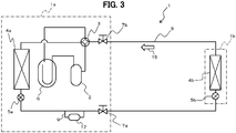
- FIG. 3 is an explanatory diagram of the configuration of the air conditioner 1 (refrigeration cycle device) according to the other embodiment of the present invention.
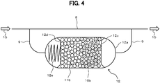
- FIG. 4 is an explanatory diagram of the configuration of the oxygen and water adsorption device 12 in the air conditioner 1 illustrated in FIG. 3 .
- the water adsorption device 11 in the air conditioner 1 illustrated in FIG. 1 is omitted in the air conditioner 1 according to the other embodiment, and the oxygen and water adsorption device 12 is disposed in place of the oxygen adsorption device 10.
- the oxygen and water adsorption device 12 is disposed on the bypass pipe 9 of the pipe 8 extending between the outdoor expansion valve 5a and the block valve 7a.
- the oxygen and water adsorption device 12 is a component of the outdoor unit 1a.
- the oxygen and water adsorption device 12 may be disposed on the pipe 8 without the bypass pipe 9.
- the oxygen and water adsorption device 12 is an integration of the oxygen adsorption device 10 (refer to FIG. 1 ) and the water adsorption device 11, and thus adsorbs oxygen and water included in refrigerant.
- the oxygen and water adsorption device 12 is disposed on the liquid pipe. In this configuration, similarly to the oxygen adsorption device 10 (refer to FIG. 1 ), the oxygen and water adsorption device 12 is disposed on the bypass pipe 9 of the pipe 8.
- the oxygen and water adsorption device 12 is disposed on the bypass pipe 9 of the pipe 8 extending between the outdoor expansion valve 5a and the block valve 7a, and is a component of the outdoor unit 1a.
- the oxygen and water adsorption device 12 may be disposed on the pipe 8 without the bypass pipe 9.
- the pipe 8 and the bypass pipe 9, on which the oxygen and water adsorption device 12 is disposed, correspond to the "pipe extending between the heat-source-side heat exchanger and the use-side heat exchanger through the expansion device" in the claims.
- a connection part between the oxygen and water adsorption device 12 and the bypass pipe 9 upstream of the oxygen and water adsorption device 12 is desirably disposed below the bifurcation part at which the bypass pipe 9 bifurcates from the pipe 8 in the vertical direction.
- the oxygen and water adsorption device 12 is more desirably disposed below the pipe 8 in the vertical direction.
- the oxygen and water adsorption device 12 has a configuration same as that of the oxygen adsorption device 10 illustrated in FIG. 2 except that the first synthetic zeolite 10b and second synthetic zeolite 11b are included in a container 12a.
- the first synthetic zeolite 10b may be same as that (refer to FIG. 2 ) used in the oxygen adsorption device 10 (refer to FIG. 1 ).
- the second synthetic zeolite 11b may be same as that (not illustrated) used in the water adsorption device 11 (refer to FIG. 1 ) .
- the second synthetic zeolite 11b is disposed upstream of the first synthetic zeolite 10b in the container 12a.
- the air conditioner 1 includes a flow-path switching mechanism (not illustrated) including a four-way valve (not illustrated) provided at an appropriate place on the pipe 8.
- the flow-path switching mechanism (not illustrated) is switched so that refrigerant flows into the container 10a through the bypass pipe 9 connected with the second synthetic zeolite 11b side.
- the oxygen and water adsorption device 12 may have a configuration in which the first synthetic zeolite 10b is disposed at a central part in the direction of refrigerant flow in the container 12a and the second synthetic zeolite 11b is disposed upstream and downstream of the first synthetic zeolite 10b in the container 12a.
- the first synthetic zeolite 10b and the second synthetic zeolite 11b are disposed in the single container 12a.
- the oxygen and water adsorption device 12 integrated of the oxygen adsorption device 10 and the water adsorption device 11
- the oxygen adsorption device 10, the water adsorption device 11, and the oxygen and water adsorption device 12 may be disposed on the pipe 8 (including a bypass pipe (not illustrated) of the pipe 8) extending between the block valve 7a and the indoor expansion valve 5b.
- the water adsorption device 11 may be omitted.
- the present invention is not limited to the air conditioner 1 according to the above-described embodiment, but is applicable to any other refrigeration cycle devicees such as a refrigerator and a heat-pump water heater.
Landscapes
- Engineering & Computer Science (AREA)
- Physics & Mathematics (AREA)
- Mechanical Engineering (AREA)
- Thermal Sciences (AREA)
- General Engineering & Computer Science (AREA)
- Chemical & Material Sciences (AREA)
- Analytical Chemistry (AREA)
- Power Engineering (AREA)
- Separation Of Gases By Adsorption (AREA)
- Solid-Sorbent Or Filter-Aiding Compositions (AREA)
- Sorption Type Refrigeration Machines (AREA)
Abstract
Description
- The present invention relates to a refrigeration cycle device such as an air conditioner, a refrigerator, or a heat-pump water heater.
- Refrigerant used in a refrigeration cycle device is required to have a low global warming potential (GWP) to achieve global warming prevention. A known low GWP refrigerant is hydrofluoro olefin (HFO). However, a low GWP refrigerant such as HFO tends to have a low chemical stability.
- In a conventionally disclosed refrigeration cycle device, an adsorption device configured to chemically adsorb oxygen and carbon dioxide is disposed in a refrigeration cycle (refer to Patent Literature 1, for example). The adsorption device removes oxygen and carbon dioxide included in refrigerant circulating through the refrigeration cycle of the refrigeration cycle device. With this configuration, resolution of the refrigerant by, for example, oxygen and carbon dioxide can be prevented in the refrigeration cycle device.
- Patent Literature 1: Japanese Patent Laid-open No.
2006-162081 - Another refrigeration cycle device includes an adsorption device configured to physically adsorb oxygen or the like in place of the above-described adsorption device (refer to Patent Literature 1, for example) that achieves chemical adsorption. Adsorbent for the physical adsorption tends to reversibly adsorb an adsorption target faster than adsorbent for chemical adsorption. Zeolite is an exemplary adsorbent for the physical adsorption. Zeolite includes fine pores on the surface thereof and adsorbs adsorption targets into the pores.
- Zeolite also adsorbs molecules of refrigerant when the pore diameter of the zeolite is larger than the molecular diameter of the refrigerant, which is typically larger than the molecular diameter of oxygen. The molecules of the refrigerant adsorbed by the zeolite are potentially resolved by catalysis of the zeolite.
- The present invention is intended to provide a refrigeration cycle device using zeolite that prevents oxidation degradation and resolution of refrigerant.
- To achieve the above-described intention, a refrigeration cycle device according to the present invention is a refrigeration cycle device including a compressor, a heat-source-side heat exchanger, an expansion device, and a use-side heat exchanger sequentially connected with each other through a pipe and using refrigerant containing hydrofluoro olefin. An oxygen adsorption device using synthetic zeolite as adsorbent is disposed halfway through the pipe. The pore diameter of a pore included in the synthetic zeolite is larger than the molecular diameter of oxygen and smaller than the molecular diameter of the hydrofluoro olefin.
- The present invention provides a refrigeration cycle device using zeolite that prevents oxidation degradation and resolution of refrigerant.
-
-
FIG. 1 is an explanatory diagram of the configuration of a refrigeration cycle device according to an embodiment of the present invention. -
FIG. 2 is an explanatory diagram of the configuration of an oxygen adsorption device in the refrigeration cycle device inFIG. 1 . -
FIG. 3 is an explanatory diagram of the configuration of a refrigeration cycle device according to another embodiment of the present invention. -
FIG. 4 is an explanatory diagram of the configuration of an oxygen and water adsorption device in the refrigeration cycle device inFIG. 3 . - Embodiments of the present invention will be described below in detail with reference to the accompanying drawings as appropriate.
- A refrigeration cycle device according to the present invention mainly includes an oxygen adsorption device using, as adsorbent, synthetic zeolite including a pore having a predetermined pore diameter.
- The following describes an air conditioner 1 as the refrigeration cycle device.
-
FIG. 1 is an explanatory diagram of the configuration of the air conditioner 1 according to the present embodiment. - As illustrated in
FIG. 1 , the air conditioner 1 includes anoutdoor unit 1a and anindoor unit 1b. - The
outdoor unit 1a includes acompressor 2, a four-way valve 3, anoutdoor heat exchanger 4a, and anoutdoor expansion valve 5a. Theindoor unit 1b includes anindoor heat exchanger 4b and anindoor expansion valve 5b. - The
outdoor heat exchanger 4a corresponds to a "heat-source-side heat exchanger" in the claims. Theindoor heat exchanger 4b corresponds to a "use-side heat exchanger" in the claims. Theoutdoor expansion valve 5a and theindoor expansion valve 5b each correspond to an "expansion device" in the claims. - The
compressor 2, theoutdoor heat exchanger 4a (heat-source-side heat exchanger), theoutdoor expansion valve 5a (expansion device), theindoor expansion valve 5b (expansion device), and theindoor heat exchanger 4b (use-side heat exchanger) are sequentially connected with each other in a ring shape through apipe 8 in the air conditioner 1. - In
FIG. 1 ,reference sign 6 denotes an accumulator disposed upstream of thecompressor 2, andreference signs block valves pipe 8 upstream and downstream of theindoor unit 1b to open and close conduction of refrigerant through thepipe 8. In the present embodiment, theblock valves outdoor unit 1a. -
Reference sign 9 denotes a bypass pipe of thepipe 8.Reference sign 10 denotes an oxygen adsorption device disposed on thebypass pipe 9.Reference sign 11 denotes a water adsorption device.Reference sign 15 denotes an arrow indicating the direction of refrigerant flow (this notation also applies in the following). - The refrigerant in the air conditioner 1 according to the present embodiment is assumed to be mixed refrigerant of hydrofluoro olefin refrigerant (for example, HFO R1234yf, HFO R1234ze(E), or HFO R1123) and hydrofluoro carbon refrigerant containing R32 refrigerant. Refrigerant oil in the air conditioner 1 according to the present embodiment is, for example, ethereal oil, ester oil, or alkyl benzene oil.
- The
oxygen adsorption device 10 and thewater adsorption device 11 will be described later in detail. - The air conditioner 1 is a heat-pump type configured to switch the four-way valve 3 to perform a cooling operation or a heating operation. In the cooling operation, the
indoor heat exchanger 4b functions as an evaporator, and theoutdoor heat exchanger 4a functions as a condenser. In the heating operation, theindoor heat exchanger 4b functions as a condenser, and theoutdoor heat exchanger 4a functions as an evaporator.FIG. 1 illustrates the switching state of the four-way valve 3 at the cooling operation. - For example, in the air conditioner 1 at the cooling operation, high-temperature and high-pressure refrigerant subjected to compression at the
compressor 2 flows into theoutdoor heat exchanger 4a through the four-way valve 3 and condenses by releasing heat through heat exchange with air. Thereafter, the refrigerant passes through theoutdoor expansion valve 5a to be subjected to isenthalpic expansion at theindoor expansion valve 5b, and becomes gas-liquid two-phase flow as mixture of gas refrigerant and liquid refrigerant at low temperature and low pressure, before flowing into theindoor heat exchanger 4b. Then, the liquid refrigerant at theindoor heat exchanger 4b vaporizes into gas refrigerant through heat absorption by air. When the liquid refrigerant vaporizes in this manner, theindoor heat exchanger 4b cools surrounding air, thereby achieving a cooling function of the air conditioner 1. Having flowed out of theindoor heat exchanger 4b, the refrigerant returns to thecompressor 2 and is subjected to compression at high temperature and high pressure, before circulating through the four-way valve 3, theoutdoor heat exchanger 4a, theindoor expansion valve 5b, and theindoor heat exchanger 4b again. Although not illustrated, in the air conditioner 1 at the heating operation, the four-way valve 3 is switched to allow the refrigerant to circulate in a direction opposite to that at the cooling operation. - At both of the cooling operation and the heating operation, the liquid refrigerant mainly flows through part (including the bypass pipe 9) of the
pipe 8, which serves as such a circulation path of the refrigerant, extending between theoutdoor expansion valve 5a and theindoor expansion valve 5b. Hereinafter, the part of thepipe 8 extending between theoutdoor expansion valve 5a and theindoor expansion valve 5b is also simply referred to as a "liquid pipe". - In the present embodiment, the
oxygen adsorption device 10, which is to be described next, and thewater adsorption device 11 are disposed on the liquid pipe. - The following describes the
oxygen adsorption device 10. - As illustrated in
FIG. 1 , theoxygen adsorption device 10 in the present embodiment is disposed on thebypass pipe 9 of thepipe 8 extending between theoutdoor expansion valve 5a and theblock valve 7a. Theoxygen adsorption device 10 is a component of theoutdoor unit 1a. Theoxygen adsorption device 10 may be disposed on thepipe 8 without thebypass pipe 9. Thepipe 8 and thebypass pipe 9, on which theoxygen adsorption device 10 is disposed, correspond to a "pipe extending between the heat-source-side heat exchanger and the use-side heat exchanger through the expansion device" in the claims. - When the
oxygen adsorption device 10 is disposed on thebypass pipe 9, a connection part between theoxygen adsorption device 10 and thebypass pipe 9 upstream of theoxygen adsorption device 10 is desirably disposed at least below a bifurcation part at which thebypass pipe 9 bifurcates from thepipe 8 in the vertical direction. Theoxygen adsorption device 10 is more desirably disposed below thepipe 8 in the vertical direction. -
FIG. 2 is an explanatory diagram of the configuration of theoxygen adsorption device 10. - As illustrated in
FIG. 2 , theoxygen adsorption device 10 includes atubular container 10a having both ends connected with thebypass pipe 9, and a firstsynthetic zeolite 10b housed in thecontainer 10a. - A pair of
support members snapping spring 10e are disposed in thecontainer 10a. Thesupport members synthetic zeolite 10b in a bead shape to be described later is not allowed to pass. In the present embodiment, thesupport members support members - Among the
support members support member 10c is disposed on downstream side inside thecontainer 10a and fixed to an inner wall surface of thecontainer 10a. The fixation of thesupport member 10c to thecontainer 10a is not limited to a particular method, but may be achieved by the well-known methods such as fitting by pressing, welding, and swaging. - Among the
support members support member 10d is disposed on upstream side inside thecontainer 10a with the firstsynthetic zeolite 10b interposed therebetween. Thesupport member 10d is slidable in the axial direction of thecontainer 10a being disposed. - The snapping
spring 10e is disposed between thesupport member 10d and an upstream-side end part inside thecontainer 10a. The snappingspring 10e presses the firstsynthetic zeolite 10b toward thesupport member 10c through thesupport member 10d by a predetermined snapping force. - With this configuration, the first
synthetic zeolite 10b, which is to be described next, fills thecontainer 10a at a predetermined density between thesupport member 10c and thesupport member 10d. - In the present embodiment, the fixed
support member 10c may be disposed on upstream side inside thecontainer 10a, whereas thesupport member 10d and the snappingspring 10e may be disposed on downstream side. - The first
synthetic zeolite 10b corresponds to "synthetic zeolite" in the claims. - The first
synthetic zeolite 10b functions differently from second synthetic zeolite that fills the water adsorption device 11 (refer toFIG. 1 ) to be described later or an oxygen and water adsorption device 12 (refer toFIG. 3 ) to be described later. The second synthetic zeolite will be described later in detail. - In the present embodiment, the first
synthetic zeolite 10b has a bead shape as described above. - The first
synthetic zeolite 10b includes a large number of pores on the surface thereof. - The pore diameter of each pore of the first
synthetic zeolite 10b is larger than the molecular diameter of oxygen and smaller than the molecular diameter of HFO refrigerant as the above-described refrigerant. - The molecular diameter of the HFO refrigerant is equal to or larger than 1.3 nm, and thus the pore diameter of each pore of the first
synthetic zeolite 10b is desirably larger than 0.34 nm and smaller than 1.3 nm. - When refrigerant containing R32 having a molecular diameter equal to or larger than 0.41 nm is used in addition to the hydrofluoro olefin as in the mixed refrigerant used in the present embodiment, the pore diameter of each pore of the first
synthetic zeolite 10b is desirably larger than 0.34 nm and smaller than 0.41 nm. - The range of the pore diameter of each pore of the first
synthetic zeolite 10b has an upper limit value defined based on the molecular diameter of the refrigerant. This definition excludes any firstsynthetic zeolite 10b including a pore that adsorbs the refrigerant. - Thus, a pore diameter that is too large to contribute to adsorption of the refrigerant is not considered as the "pore diameter of a pore included in the synthetic zeolite" in the claims. In other words, any synthetic zeolite having a pore diameter that is too large to contribute to adsorption of the refrigerant belongs to the first
synthetic zeolite 10b in the present embodiment when the pore diameter is larger than the molecular diameter of oxygen and smaller than the molecular diameter of HFO refrigerant as the above-described refrigerant. The pore diameter that is too large to contribute to adsorption of the refrigerant has a lower limit value of 100 nm, preferably 10 nm. - Synthetic zeolite including a pore having a pore diameter in the range is selectively used as the first
synthetic zeolite 10b. The pore diameter of a pore is measured by a gas adsorption method using argon, but is not limited thereto. Any method that is capable of performing sub-nanometer order measurement of the pore diameter of a pore is applicable. - The first
synthetic zeolite 10b is obtained by, for example, desorbing crystalline water from crystalline zeolite (aqueous metallic salt of synthetic crystal aluminosilicate). - In the first
synthetic zeolite 10b obtained from the crystalline zeolite, a pore having a uniform pore diameter in the order of 0.1 nm is formed as a hollow space left behind after the desorption of the crystalline water. The firstsynthetic zeolite 10b is desirably a molecular sieve. - The first
synthetic zeolite 10b may be a commercially available product, and thus any product including a pore having a pore diameter in the above-described range can be selected based on a catalog value. - The first
synthetic zeolite 10b is desirably hydrophobic. Examples of the hydrophobic firstsynthetic zeolite 10b include what is called high-silica zeolite that is aqueous metallic salt of synthetic crystal aluminosilicate having an increased ratio of SiO2. The hydrophobic firstsynthetic zeolite 10b loses an affinity to polar material due to, for example, decrease of the ratio of metallic cation existing in crystal lattice, which is caused by the increased ratio of SiO2. This high-silica zeolite may be a commercially available product. - The hydrophobic first
synthetic zeolite 10b thus has a poor affinity to polar material such as water as described above (or loses the affinity), and relatively aggressively adsorbs non-polar material. - The following describes the
water adsorption device 11. - As illustrated in
FIG. 1 , thewater adsorption device 11 according to the present embodiment is disposed on the pipe 8 (including the bypass pipe 9) extending between theoutdoor expansion valve 5a and theblock valve 7a. Thewater adsorption device 11 is a component of theoutdoor unit 1a. Thewater adsorption device 11 is disposed on thepipe 8 upstream of theoxygen adsorption device 10.FIG. 1 illustrates the air conditioner 1 at the cooling operation. Thus, although not illustrated, the air conditioner 1 according to the present embodiment includes anotherwater adsorption device 11 for the heating operation. The flow path of refrigerant is switched depending on whether the cooling operation or the heating operation is performed so that any one of thesewater adsorption devices 11 is positioned upstream of theoxygen adsorption device 10. Although not illustrated, thewater adsorption devices 11 may be disposed upstream and downstream of theoxygen adsorption device 10. - Although not illustrated, the
water adsorption device 11 has a configuration same as that of theoxygen adsorption device 10 except that thecontainer 10a is filled with the second synthetic zeolite in place of the firstsynthetic zeolite 10b of theoxygen adsorption device 10 illustrated inFIG. 2 . Since thewater adsorption device 11 is disposed on thepipe 8,reference sign 9 inFIG. 2 is replaced withreference sign 8. - The second synthetic zeolite (not illustrated) has a bead shape.
- The pore diameter of each pore of the second synthetic zeolite is larger than the molecular diameter (0.28 nm) of water and smaller than the molecular diameter of HFO refrigerant as the above-described refrigerant.
- The molecular diameter of the HFO refrigerant is equal to or larger than 1.3 nm, and thus the pore diameter of each pore of the second synthetic zeolite is desirably larger than 0.28 nm and smaller than 1.3 nm.
- When refrigerant containing R32 having a molecular diameter equal to or larger than 0.41 nm is used in addition to the hydrofluoro olefin as in the mixed refrigerant used in the present embodiment, the pore diameter of each pore of the second synthetic zeolite is desirably larger than 0.28 nm and smaller than 0.41 nm.
- The range of the pore diameter of each pore of the second synthetic zeolite has an upper limit value defined based on the molecular diameter of the refrigerant like the upper limit value of the range of the pore diameter of each pore of the first
synthetic zeolite 10b (refer toFIG. 2 ) described above. This upper limit value is defined to exclude any second synthetic zeolite including a pore that adsorbs the refrigerant. - Thus, any synthetic zeolite having a pore diameter that is too large to contribute to adsorption of the refrigerant belongs to the second synthetic zeolite in the present embodiment when the pore diameter is larger than the molecular diameter of oxygen and smaller than the molecular diameter of HFO refrigerant as the above-described refrigerant.
- Similarly to the first
synthetic zeolite 10b (refer toFIG. 2 ) described above, the second synthetic zeolite is obtained by, for example, desorbing crystalline water from crystalline zeolite (aqueous metallic salt of synthetic crystal aluminosilicate). - The second synthetic zeolite is desirably a molecular sieve.
- The second synthetic zeolite may be a commercially available product, and thus any product including a pore having a pore diameter in the above-described range can be selected based on a catalog value.
- The second synthetic zeolite is desirably non-hydrophobic, and is more desirably hydrophilic. The non-hydrophobic second synthetic zeolite can be obtained by reducing the ratio of SiO2 in aqueous metallic salt of synthetic crystal aluminosilicate described above to a value smaller than that in the first
synthetic zeolite 10b (refer toFIG. 2 ) described above. - Nitrogen and carbon dioxide in air include electric quadrupoles in their molecules. Thus, nitrogen and carbon dioxide are non-polar molecules like oxygen, but are more likely to be adsorbed by the second synthetic zeolite (not illustrated) than oxygen.
- Accordingly, nitrogen (molecular diameter: 0.36 nm) and carbon dioxide (molecular diameter: 0.34 nm) can be removed by the
water adsorption device 11, for example, when the pore diameter of each pore of the second synthetic zeolite is set to be equal to or smaller than 0.36 nm. Nitrogen (molecular diameter: 0.36 nm) and carbon dioxide (molecular diameter: 0.34 nm) can be removed by theoxygen adsorption device 10, for example, when the pore diameter of each pore of the second synthetic zeolite is set to be smaller than 0.34 nm. - The following describes any effect achieved by the air conditioner 1 according to the present embodiment (refer to
FIG. 1 ). - When the air conditioner 1 is installed at a predetermined place, for example, air remaining in the
pipe 8 or any cycle component is discharged out of the system of the air conditioner 1 by a vacuum pump. Any air or the like remaining in the system of the air conditioner 1 would cause oxidation degradation of refrigerant, and thus needs to be thoroughly discharged out of the system. - When HFO refrigerant having low chemical stability is used, for example, air (oxygen) in such an amount that causes no problem to HFC refrigerant causes resolution of the HFO refrigerant. Any remaining product through the resolution of the HFO refrigerant potentially degrades the refrigerant oil. In addition, hydrofluoric acid produced through the resolution of the HFO refrigerant causes chained resolution of the HFO refrigerant.
- When the produced hydrofluoric acid circulates through the refrigeration cycle along with the refrigerant, abrasion is promoted at a sliding part (not illustrated) of the compressor 2 (refer to
FIG. 1 ). In addition, abnormal noise in operation is generated by copper plating phenomenon occurring at a bearing (not illustrated) of the compressor 2 (refer toFIG. 1 ) in some cases. - To avoid these, zeolite may be used as adsorbent to remove oxygen included in the refrigerant. However, zeolite adsorbs HFO refrigerant as well as oxygen. Moreover, the HFO refrigerant adsorbed by zeolite is potentially resolved by catalysis of zeolite.
- The air conditioner 1 according to the present embodiment (refer to
FIG. 1 ) includes the oxygen adsorption device 10 (refer toFIG. 2 ) provided with the firstsynthetic zeolite 10b (refer toFIG. 2 ) that adsorbs any acid included in refrigerant. - The pore diameter of a pore included in the first
synthetic zeolite 10b is larger than the molecular diameter of oxygen and smaller than the molecular diameter of HFO refrigerant. - With this configuration, in the air conditioner 1 according to the present embodiment, the
oxygen adsorption device 10 adsorbs oxygen included in the refrigerant, but does not adsorb the HFO refrigerant. - Accordingly, oxidation degradation and resolution of the HFO refrigerant by catalysis of zeolite can be prevented in the air conditioner 1, thereby achieving increased reliability of the air conditioner 1.
- In the air conditioner 1, in which the pore diameter of a pore included in the first
synthetic zeolite 10b (refer toFIG. 2 ) is larger than 0.34 nm and smaller than 1.3 nm, adsorption of the HFO refrigerant can be more reliably prevented at theoxygen adsorption device 10. Accordingly, resolution of the HFO refrigerant can be more reliably prevented in the air conditioner 1. - In the air conditioner 1, in which the pore diameter of a pore included in the first
synthetic zeolite 10b (refer toFIG. 2 ) is larger than 0.34 nm and smaller than 0.41 nm, adsorption of the R32 refrigerant by the firstsynthetic zeolite 10b can be prevented when the mixed refrigerant of the HFO refrigerant and the R32 refrigerant is used. - In the air conditioner 1 according to the present embodiment, the
water adsorption device 11, which uses the non-hydrophobic or preferably hydrophilic second synthetic zeolite (not illustrated) as adsorbent, is disposed separately from theoxygen adsorption device 10. Thewater adsorption device 11 removes, in advance, water in HFO refrigerant to be supplied to theoxygen adsorption device 10. - In the air conditioner 1 thus configured, since the
water adsorption device 11 removes, in advance, water in the HFO refrigerant to be supplied to theoxygen adsorption device 10, theoxygen adsorption device 10 can adsorb a larger amount of oxygen. - The second synthetic zeolite (not illustrated) is likely to adsorb polar material such as refrigerant in addition to water. Thus, in the air conditioner 1, in which the pore diameter of each pore of the second synthetic zeolite (not illustrated) is larger than the molecular diameter (0.28 nm) of water and smaller than the molecular diameter of HFO refrigerant, water is excellently adsorbed, and the HFO refrigerant is hardly adsorbed. Accordingly, in the air conditioner 1, a larger amount of oxygen can be adsorbed by the
oxygen adsorption device 10, and resolution of the HFO refrigerant can be more reliably prevented. - In the air conditioner 1 according to the present embodiment, the
oxygen adsorption device 10 and thewater adsorption device 11 are disposed halfway through the above-described liquid pipe. - Water included in refrigerant is included in a larger amount in liquid refrigerant than gas refrigerant. Thus, in the air conditioner 1 according to the present embodiment, in which the
water adsorption device 11 is disposed on the liquid pipe, water can be efficiently removed as compared to a case in which thewater adsorption device 11 is disposed on thepipe 8 through which, for example, gas refrigerant or gas-liquid two-phase refrigerant flows. - The
oxygen adsorption device 10 and thewater adsorption device 11 are disposed on the liquid pipe through which refrigerant flows far more slowly than in thepipe 8 through which gas refrigerant or gas-liquid two-phase refrigerant flows. Accordingly, the firstsynthetic zeolite 10b and the second synthetic zeolite (not illustrated) are more reliably held in theoxygen adsorption device 10 and thewater adsorption device 11. - In the air conditioner 1 according to the present embodiment, the
oxygen adsorption device 10 is disposed on thebypass pipe 9 of thepipe 8. - In the
bypass pipe 9 bifurcating from thepipe 8, a bifurcation loss occurs when refrigerant flows from thepipe 8 to thebypass pipe 9. Thus, the refrigerant flows through thebypass pipe 9 more slowly than through thepipe 8. Specifically, for example, when thepipe 8 and thebypass pipe 9 have identical inner diameters, the flow speed of the refrigerant flowing through thebypass pipe 9 is a few percent to ten percent, approximately, of the flow speed of the refrigerant flowing through thepipe 8. Accordingly, in the air conditioner 1, the firstsynthetic zeolite 10b can be further reliably held in theoxygen adsorption device 10. - In the air conditioner 1, as described above, the connection part between the
oxygen adsorption device 10 and thebypass pipe 9 upstream of theoxygen adsorption device 10 is desirably disposed below the bifurcation part at which thebypass pipe 9 bifurcates from thepipe 8 in the vertical direction. Theoxygen adsorption device 10 is more desirably disposed below thepipe 8 in the vertical direction in the air conditioner 1. - In the air conditioner 1 thus configured, the liquid refrigerant preferentially flows through the
bypass pipe 9 when refrigerant flowing inside thepipe 8 is gas-liquid two-phase flow (for example, annular dispersed flow, plug flow, or chain flow) like a case in which the air conditioner 1 operates in a transient state, for example. - Accordingly, the first
synthetic zeolite 10b is further reliably held in theoxygen adsorption device 10. - Although the present embodiment is described above, the present invention is not limited to the embodiment but can be achieved in various kinds of embodiments. In another embodiment described below, any component identical to that in the above-described embodiment is denoted by an identical reference sign, and detailed description thereof is omitted.
- Although the air conditioner 1 includes the
oxygen adsorption device 10 and thewater adsorption device 11 in the above-described embodiment, the oxygen and water adsorption device 12 (refer toFIG. 3 ) may be included in place of theoxygen adsorption device 10 and thewater adsorption device 11. -
FIG. 3 is an explanatory diagram of the configuration of the air conditioner 1 (refrigeration cycle device) according to the other embodiment of the present invention.FIG. 4 is an explanatory diagram of the configuration of the oxygen andwater adsorption device 12 in the air conditioner 1 illustrated inFIG. 3 . - As illustrated in
FIG. 3 , thewater adsorption device 11 in the air conditioner 1 illustrated inFIG. 1 is omitted in the air conditioner 1 according to the other embodiment, and the oxygen andwater adsorption device 12 is disposed in place of theoxygen adsorption device 10. In this configuration, the oxygen andwater adsorption device 12 is disposed on thebypass pipe 9 of thepipe 8 extending between theoutdoor expansion valve 5a and theblock valve 7a. The oxygen andwater adsorption device 12 is a component of theoutdoor unit 1a. - The oxygen and
water adsorption device 12 may be disposed on thepipe 8 without thebypass pipe 9. Thepipe 8 and thebypass pipe 9, on which the oxygen andwater adsorption device 12 is disposed, correspond to the "pipe extending between the heat-source-side heat exchanger and the use-side heat exchanger through the expansion device" in the claims. - The following describes the oxygen and
water adsorption device 12. - The oxygen and
water adsorption device 12 is an integration of the oxygen adsorption device 10 (refer toFIG. 1 ) and thewater adsorption device 11, and thus adsorbs oxygen and water included in refrigerant. - The oxygen and
water adsorption device 12 is disposed on the liquid pipe. In this configuration, similarly to the oxygen adsorption device 10 (refer toFIG. 1 ), the oxygen andwater adsorption device 12 is disposed on thebypass pipe 9 of thepipe 8. - In the present embodiment, the oxygen and
water adsorption device 12 is disposed on thebypass pipe 9 of thepipe 8 extending between theoutdoor expansion valve 5a and theblock valve 7a, and is a component of theoutdoor unit 1a. The oxygen andwater adsorption device 12 may be disposed on thepipe 8 without thebypass pipe 9. Thepipe 8 and thebypass pipe 9, on which the oxygen andwater adsorption device 12 is disposed, correspond to the "pipe extending between the heat-source-side heat exchanger and the use-side heat exchanger through the expansion device" in the claims. - When the oxygen and
water adsorption device 12 is disposed on thebypass pipe 9, a connection part between the oxygen andwater adsorption device 12 and thebypass pipe 9 upstream of the oxygen andwater adsorption device 12 is desirably disposed below the bifurcation part at which thebypass pipe 9 bifurcates from thepipe 8 in the vertical direction. The oxygen andwater adsorption device 12 is more desirably disposed below thepipe 8 in the vertical direction. - As illustrated in
FIG. 4 , the oxygen andwater adsorption device 12 has a configuration same as that of theoxygen adsorption device 10 illustrated inFIG. 2 except that the firstsynthetic zeolite 10b and secondsynthetic zeolite 11b are included in acontainer 12a. - The first
synthetic zeolite 10b may be same as that (refer toFIG. 2 ) used in the oxygen adsorption device 10 (refer toFIG. 1 ). - The second
synthetic zeolite 11b may be same as that (not illustrated) used in the water adsorption device 11 (refer toFIG. 1 ) . - As illustrated in
FIG. 4 , in the oxygen andwater adsorption device 12, the secondsynthetic zeolite 11b is disposed upstream of the firstsynthetic zeolite 10b in thecontainer 12a. - Although not illustrated in
FIG. 3 , the air conditioner 1 includes a flow-path switching mechanism (not illustrated) including a four-way valve (not illustrated) provided at an appropriate place on thepipe 8. In the air conditioner 1, depending on whether the cooling operation or the heating operation is performed, the flow-path switching mechanism (not illustrated) is switched so that refrigerant flows into thecontainer 10a through thebypass pipe 9 connected with the secondsynthetic zeolite 11b side. - Although not illustrated in
FIG. 4 , the oxygen andwater adsorption device 12 may have a configuration in which the firstsynthetic zeolite 10b is disposed at a central part in the direction of refrigerant flow in thecontainer 12a and the secondsynthetic zeolite 11b is disposed upstream and downstream of the firstsynthetic zeolite 10b in thecontainer 12a. - In the oxygen and
water adsorption device 12 illustrated inFIG. 4 , the firstsynthetic zeolite 10b and the secondsynthetic zeolite 11b are disposed in thesingle container 12a. However, although not illustrated, the oxygen and water adsorption device 12 (integration of theoxygen adsorption device 10 and the water adsorption device 11) may include individual containers separately including the firstsynthetic zeolite 10b and the secondsynthetic zeolite 11b, respectively. - In the air conditioner 1, the
oxygen adsorption device 10, thewater adsorption device 11, and the oxygen andwater adsorption device 12 may be disposed on the pipe 8 (including a bypass pipe (not illustrated) of the pipe 8) extending between theblock valve 7a and theindoor expansion valve 5b. - In the air conditioner 1 illustrated in
FIG. 1 , thewater adsorption device 11 may be omitted. - The present invention is not limited to the air conditioner 1 according to the above-described embodiment, but is applicable to any other refrigeration cycle devicees such as a refrigerator and a heat-pump water heater.
-
- 1
- air conditioner (refrigeration cycle device)
- 1a
- outdoor unit
- 1b
- indoor unit
- 2
- compressor
- 3
- four-way valve
- 4a
- outdoor heat exchanger (heat-source-side heat exchanger)
- 4b
- indoor heat exchanger (use-side heat exchanger)
- 5a
- outdoor expansion valve (expansion device)
- 5b
- indoor expansion valve (expansion device)
- 9
- bypass pipe
- 10
- oxygen adsorption device
- 10b
- first synthetic zeolite
- 11
- water adsorption device
- 11b
- the second synthetic zeolite
- 12
- oxygen and water adsorption device
Claims (7)
- A refrigeration cycle device including a compressor, a heat-source-side heat exchanger, an expansion device, and a use-side heat exchanger sequentially connected with each other through a pipe and using refrigerant containing hydrofluoro olefin, wherein
an oxygen adsorption device using synthetic zeolite as adsorbent is disposed halfway through the pipe, and
the pore diameter of a pore included in the synthetic zeolite is larger than the molecular diameter of oxygen and smaller than the molecular diameter of the hydrofluoro olefin. - The refrigeration cycle device according to claim 1, wherein the pore diameter of the pore included in the synthetic zeolite is larger than 0.34 nm and smaller than 1.3 nm.
- The refrigeration cycle device according to claim 1, wherein
refrigerant containing R32 in addition to the hydrofluoro olefin is used, and
the pore diameter of a pore included in the synthetic zeolite is larger than 0.34 nm and smaller than 0.41 nm. - The refrigeration cycle device according to claim 1, wherein the synthetic zeolite is hydrophobic.
- The refrigeration cycle device according to claim 1, wherein a water adsorption device using non-hydrophobic synthetic zeolite as adsorbent is disposed halfway through the pipe and separately from the oxygen adsorption device.
- The refrigeration cycle device according to claim 5, wherein the oxygen adsorption device and the water adsorption device are disposed halfway through the pipe extending between the heat-source-side heat exchanger and the use-side heat exchanger through the expansion device.
- The refrigeration cycle device according to claim 6, wherein the oxygen adsorption device and the water adsorption device integrally function as an oxygen and water adsorption device.
Applications Claiming Priority (1)
| Application Number | Priority Date | Filing Date | Title |
|---|---|---|---|
| PCT/JP2015/065329 WO2016189717A1 (en) | 2015-05-28 | 2015-05-28 | Refrigeration cycle device |
Publications (2)
| Publication Number | Publication Date |
|---|---|
| EP3306225A1 true EP3306225A1 (en) | 2018-04-11 |
| EP3306225A4 EP3306225A4 (en) | 2019-01-23 |
Family
ID=57393925
Family Applications (1)
| Application Number | Title | Priority Date | Filing Date |
|---|---|---|---|
| EP15893351.5A Pending EP3306225A4 (en) | 2015-05-28 | 2015-05-28 | REFRIGERANT CYCLE DEVICE |
Country Status (5)
| Country | Link |
|---|---|
| US (1) | US10267549B2 (en) |
| EP (1) | EP3306225A4 (en) |
| JP (1) | JPWO2016189717A1 (en) |
| CN (1) | CN107850345A (en) |
| WO (1) | WO2016189717A1 (en) |
Cited By (1)
| Publication number | Priority date | Publication date | Assignee | Title |
|---|---|---|---|---|
| US11692746B2 (en) | 2018-06-05 | 2023-07-04 | Carrier Corporation | System and method for evaporative cooling and heating |
Families Citing this family (5)
| Publication number | Priority date | Publication date | Assignee | Title |
|---|---|---|---|---|
| JP6524990B2 (en) * | 2016-12-09 | 2019-06-05 | ダイキン工業株式会社 | Heat transfer device and heat transfer method using the same |
| US11377578B2 (en) * | 2016-12-13 | 2022-07-05 | Daikin Industries, Ltd. | Heat transfer device and heat transfer method using same |
| JP7192347B2 (en) * | 2018-09-21 | 2022-12-20 | 株式会社富士通ゼネラル | refrigeration cycle equipment |
| FR3086287B1 (en) * | 2018-09-26 | 2020-09-18 | Arkema France | STABILIZATION OF 1-CHLORO-3,3,3-TRIFLUOROPROPENE |
| US11162705B2 (en) | 2019-08-29 | 2021-11-02 | Hitachi-Johnson Controls Air Conditioning, Inc | Refrigeration cycle control |
Family Cites Families (24)
| Publication number | Priority date | Publication date | Assignee | Title |
|---|---|---|---|---|
| US3513661A (en) * | 1968-09-09 | 1970-05-26 | Danfoss As | Desiccant-control of refrigerant compressor head pressure |
| JP2757610B2 (en) * | 1991-08-29 | 1998-05-25 | ダイキン工業株式会社 | Bleeding device for refrigerator |
| JPH0569571U (en) * | 1992-02-28 | 1993-09-21 | 株式会社東芝 | Separate type cooling device |
| JPH07159004A (en) * | 1993-12-09 | 1995-06-20 | Hitachi Ltd | Refrigeration cycle and air conditioner |
| JPH07243721A (en) * | 1994-03-09 | 1995-09-19 | Matsushita Refrig Co Ltd | Refrigerating system |
| JP3592514B2 (en) * | 1998-03-02 | 2004-11-24 | 松下電器産業株式会社 | Refrigeration equipment |
| JP2000039236A (en) * | 1998-07-24 | 2000-02-08 | Hitachi Ltd | Air conditioner |
| JP2004002160A (en) * | 2002-03-28 | 2004-01-08 | Toray Ind Inc | Method for coating zeolite crystal, substrate coated with zeolite crystal, method for producing zeolite membrane, zeolite membrane, and separation method using zeolite membrane |
| JP4221598B2 (en) | 2004-12-02 | 2009-02-12 | 日立アプライアンス株式会社 | Refrigeration cycle equipment |
| US8500852B2 (en) | 2006-05-05 | 2013-08-06 | Separation Design Group, Llc | Sorption method, device, and system |
| JP2007315663A (en) * | 2006-05-25 | 2007-12-06 | Sanden Corp | Refrigeration system |
| JP2008267680A (en) * | 2007-04-19 | 2008-11-06 | Sanden Corp | Refrigerating circuit |
| EP2312241B1 (en) * | 2008-06-24 | 2019-11-27 | Mitsubishi Electric Corporation | Refrigerating cycle apparatus, and air-conditioning apparatus |
| JP2010121927A (en) * | 2008-10-22 | 2010-06-03 | Panasonic Corp | Cooling cycle device |
| JP5715752B2 (en) * | 2008-12-01 | 2015-05-13 | 日立アプライアンス株式会社 | Refrigeration cycle equipment |
| JP2011096559A (en) * | 2009-10-30 | 2011-05-12 | Sanyo Electric Co Ltd | Fuel cell module |
| JP2013083212A (en) * | 2011-10-11 | 2013-05-09 | Isuzu Motors Ltd | Internal combustion engine, vehicle equipped with the same, and starting method of internal combustion engine |
| JP2014062768A (en) * | 2012-09-20 | 2014-04-10 | Hitachi Powdered Metals Co Ltd | Diffusion-control member for light water reactor |
| JP2014228154A (en) * | 2013-05-20 | 2014-12-08 | 日立アプライアンス株式会社 | Air conditioner |
| EP3012555B1 (en) | 2013-06-19 | 2021-01-13 | Mitsubishi Electric Corporation | Refrigeration cycle device |
| JP2015021683A (en) * | 2013-07-22 | 2015-02-02 | パナソニック株式会社 | Refrigeration equipment |
| JP6429778B2 (en) * | 2013-08-12 | 2018-11-28 | 共同印刷株式会社 | Adsorbent composition, adsorbent-containing film and method for producing the same |
| JP2015055455A (en) * | 2013-09-13 | 2015-03-23 | 三菱電機株式会社 | Outdoor unit and air conditioner |
| US9415996B2 (en) * | 2014-08-18 | 2016-08-16 | BlackPak, Inc. | Sorption pumps and storage for gases |
-
2015
- 2015-05-28 WO PCT/JP2015/065329 patent/WO2016189717A1/en not_active Ceased
- 2015-05-28 US US15/577,370 patent/US10267549B2/en active Active
- 2015-05-28 JP JP2017520173A patent/JPWO2016189717A1/en active Pending
- 2015-05-28 EP EP15893351.5A patent/EP3306225A4/en active Pending
- 2015-05-28 CN CN201580080481.4A patent/CN107850345A/en active Pending
Cited By (1)
| Publication number | Priority date | Publication date | Assignee | Title |
|---|---|---|---|---|
| US11692746B2 (en) | 2018-06-05 | 2023-07-04 | Carrier Corporation | System and method for evaporative cooling and heating |
Also Published As
| Publication number | Publication date |
|---|---|
| WO2016189717A1 (en) | 2016-12-01 |
| US10267549B2 (en) | 2019-04-23 |
| CN107850345A (en) | 2018-03-27 |
| US20180164007A1 (en) | 2018-06-14 |
| EP3306225A4 (en) | 2019-01-23 |
| JPWO2016189717A1 (en) | 2018-04-12 |
Similar Documents
| Publication | Publication Date | Title |
|---|---|---|
| US10267549B2 (en) | Refrigeration cycle device | |
| EP2312241B1 (en) | Refrigerating cycle apparatus, and air-conditioning apparatus | |
| US20140374066A1 (en) | Bubble-removal device, outdoor heat-exchange device, and refrigeration/air-conditioning system | |
| EP2339271A1 (en) | Cooling cycle device | |
| EP3404342A1 (en) | Refrigeration cycle device and heat cycle system | |
| JP7284754B2 (en) | Heat transfer composition, method and system | |
| CN111316049A (en) | Heat transfer methods, systems, and compositions | |
| US11661540B2 (en) | Refrigeration apparatus | |
| KR102421874B1 (en) | Low GWP Cascade Refrigeration System | |
| CN108291756B (en) | Refrigerant processing device and refrigeration and air conditioning system | |
| WO2016071955A1 (en) | Air conditioning apparatus | |
| Li et al. | Effect of lubricant on two-phase refrigerant distribution in microchannel evaporator | |
| JP2009300001A (en) | Refrigerating cycle device | |
| JP2019184236A (en) | Heat transfer device and heat transfer method using the same | |
| JP2011247482A (en) | Refrigeration device and cooling and heating device | |
| US10648710B2 (en) | Heat pump system and cooling generation method | |
| JP2020180718A (en) | Refrigerant recovery device | |
| JP2008267680A (en) | Refrigerating circuit | |
| JP5137726B2 (en) | Air conditioner | |
| JP2020051630A (en) | Refrigeration cycle device | |
| JPH09159325A (en) | Refrigeration cycle device with dryer | |
| WO2025182543A1 (en) | Odorant removal method, filter, deodorization device, and refrigeration cycle device | |
| Bowers et al. | Evaluation of Seasonal Performance Improvements in a 3-Ton Air-Conditioning Heat Pump System Using a Novel Design of Integrated Electronic Expansion Valves and Distributors. | |
| JP2017198362A (en) | Refrigeration cycle apparatus | |
| JP2004293945A (en) | Refrigeration equipment |
Legal Events
| Date | Code | Title | Description |
|---|---|---|---|
| STAA | Information on the status of an ep patent application or granted ep patent |
Free format text: STATUS: THE INTERNATIONAL PUBLICATION HAS BEEN MADE |
|
| PUAI | Public reference made under article 153(3) epc to a published international application that has entered the european phase |
Free format text: ORIGINAL CODE: 0009012 |
|
| STAA | Information on the status of an ep patent application or granted ep patent |
Free format text: STATUS: REQUEST FOR EXAMINATION WAS MADE |
|
| 17P | Request for examination filed |
Effective date: 20180102 |
|
| AK | Designated contracting states |
Kind code of ref document: A1 Designated state(s): AL AT BE BG CH CY CZ DE DK EE ES FI FR GB GR HR HU IE IS IT LI LT LU LV MC MK MT NL NO PL PT RO RS SE SI SK SM TR |
|
| AX | Request for extension of the european patent |
Extension state: BA ME |
|
| DAV | Request for validation of the european patent (deleted) | ||
| DAX | Request for extension of the european patent (deleted) | ||
| A4 | Supplementary search report drawn up and despatched |
Effective date: 20190102 |
|
| RIC1 | Information provided on ipc code assigned before grant |
Ipc: F25B 13/00 20060101ALI20181218BHEP Ipc: F25B 1/00 20060101AFI20181218BHEP Ipc: F25B 47/00 20060101ALI20181218BHEP Ipc: F25B 43/04 20060101ALI20181218BHEP |
|
| STAA | Information on the status of an ep patent application or granted ep patent |
Free format text: STATUS: EXAMINATION IS IN PROGRESS |
|
| 17Q | First examination report despatched |
Effective date: 20220311 |