EP3306224A1 - Solar heat collection device and preheating method of heat collection tube - Google Patents
Solar heat collection device and preheating method of heat collection tube Download PDFInfo
- Publication number
- EP3306224A1 EP3306224A1 EP15893337.4A EP15893337A EP3306224A1 EP 3306224 A1 EP3306224 A1 EP 3306224A1 EP 15893337 A EP15893337 A EP 15893337A EP 3306224 A1 EP3306224 A1 EP 3306224A1
- Authority
- EP
- European Patent Office
- Prior art keywords
- collecting tube
- heat collecting
- reflecting plate
- heat
- angle
- Prior art date
- Legal status (The legal status is an assumption and is not a legal conclusion. Google has not performed a legal analysis and makes no representation as to the accuracy of the status listed.)
- Withdrawn
Links
Images

Classifications
-
- F—MECHANICAL ENGINEERING; LIGHTING; HEATING; WEAPONS; BLASTING
- F24—HEATING; RANGES; VENTILATING
- F24S—SOLAR HEAT COLLECTORS; SOLAR HEAT SYSTEMS
- F24S30/00—Arrangements for moving or orienting solar heat collector modules
- F24S30/40—Arrangements for moving or orienting solar heat collector modules for rotary movement
- F24S30/42—Arrangements for moving or orienting solar heat collector modules for rotary movement with only one rotation axis
- F24S30/425—Horizontal axis
-
- F—MECHANICAL ENGINEERING; LIGHTING; HEATING; WEAPONS; BLASTING
- F24—HEATING; RANGES; VENTILATING
- F24S—SOLAR HEAT COLLECTORS; SOLAR HEAT SYSTEMS
- F24S23/00—Arrangements for concentrating solar-rays for solar heat collectors
- F24S23/70—Arrangements for concentrating solar-rays for solar heat collectors with reflectors
- F24S23/74—Arrangements for concentrating solar-rays for solar heat collectors with reflectors with trough-shaped or cylindro-parabolic reflective surfaces
-
- F—MECHANICAL ENGINEERING; LIGHTING; HEATING; WEAPONS; BLASTING
- F24—HEATING; RANGES; VENTILATING
- F24S—SOLAR HEAT COLLECTORS; SOLAR HEAT SYSTEMS
- F24S50/00—Arrangements for controlling solar heat collectors
- F24S50/80—Arrangements for controlling solar heat collectors for controlling collection or absorption of solar radiation
-
- F—MECHANICAL ENGINEERING; LIGHTING; HEATING; WEAPONS; BLASTING
- F24—HEATING; RANGES; VENTILATING
- F24S—SOLAR HEAT COLLECTORS; SOLAR HEAT SYSTEMS
- F24S80/00—Details, accessories or component parts of solar heat collectors not provided for in groups F24S10/00-F24S70/00
- F24S80/20—Working fluids specially adapted for solar heat collectors
-
- F—MECHANICAL ENGINEERING; LIGHTING; HEATING; WEAPONS; BLASTING
- F24—HEATING; RANGES; VENTILATING
- F24S—SOLAR HEAT COLLECTORS; SOLAR HEAT SYSTEMS
- F24S10/00—Solar heat collectors using working fluids
- F24S10/40—Solar heat collectors using working fluids in absorbing elements surrounded by transparent enclosures, e.g. evacuated solar collectors
- F24S10/45—Solar heat collectors using working fluids in absorbing elements surrounded by transparent enclosures, e.g. evacuated solar collectors the enclosure being cylindrical
-
- Y—GENERAL TAGGING OF NEW TECHNOLOGICAL DEVELOPMENTS; GENERAL TAGGING OF CROSS-SECTIONAL TECHNOLOGIES SPANNING OVER SEVERAL SECTIONS OF THE IPC; TECHNICAL SUBJECTS COVERED BY FORMER USPC CROSS-REFERENCE ART COLLECTIONS [XRACs] AND DIGESTS
- Y02—TECHNOLOGIES OR APPLICATIONS FOR MITIGATION OR ADAPTATION AGAINST CLIMATE CHANGE
- Y02E—REDUCTION OF GREENHOUSE GAS [GHG] EMISSIONS, RELATED TO ENERGY GENERATION, TRANSMISSION OR DISTRIBUTION
- Y02E10/00—Energy generation through renewable energy sources
- Y02E10/40—Solar thermal energy, e.g. solar towers
- Y02E10/47—Mountings or tracking
Definitions
- the present invention relates to a solar thermal collector that heats a heat medium flowing in a heat collecting tube by collecting sunlight.
- Solar thermal power generation systems are known that generate electric power by collecting sunlight to a heat collecting tube using a reflecting mirror so as to heat a heat medium flowing in the heat collecting tube, generating steam using the heated heat medium, and rotating a steam turbine.
- the cost of installing solar thermal power generation systems is lower than that of photovoltaic power generation systems.
- solar thermal power generation systems can generate electricity on a 24-hour basis by collecting heat.
- solar thermal power generation systems that use oil as a heat medium are proposed (see, for example, patent document 1).
- molten salt has attracted attention as a heat medium for use in solar thermal power generation systems.
- Molten salt has a high boiling point. With the use of molten salt, the operating temperature can be relatively high and power generating efficiency is improved by generating high-temperature steam.
- Molten salt is solidified at about 250°C. If the temperature of the heat collecting tube is relatively low when molten salt is run into the heat collecting tube at a startup or after a maintenance activity, therefore, the molten salt is deprived of heat by the heat collecting tube and could be solidified. For this reason, it is necessary to preheat the heat-collecting tube to a predetermined temperature or higher before molten salt is run to the heat-collecting tube.
- One conceivable method to preheat the heat-collecting tube is to induce an electric current in the heat-collecting tube. By inducing an electric current, the Joule heat can warm the heat-collecting tube.
- the preheating method described above of inducing an electric current in the heat-collecting tube has a drawback in that it requires an extremely large electric power and increases the cost.
- the present invention has been made in view of the foregoing circumstances, and a purpose of the invention is to provide a technology adapted for solar thermal collectors capable of preheating a heat-collecting tube at a low cost.
- a solar-thermal collector includes: a heat collecting tube in which a heat medium is caused to flow; a reflecting plate having a parabolic cross section that collects sunlight to the heat collecting tube; and a rotating device that rotates the heat collecting tube and the reflecting plate around a rotational shaft.
- the rotating device rotates the heat collecting tube and the reflecting plate, when preheating the heat collecting tube before the heat medium is introduced, such that an angle of the sunlight relative to the ground and an angle of an axis of symmetry of the reflecting plate relative to the ground are different.
- the rotating device may rotate the heat collecting tube and the reflecting plate, when preheating the heat collecting tube before the heat medium is introduced, such that an angle difference between the angle of the sunlight and the angle of the axis of symmetry of the reflecting plate differ is a predetermined angle difference.
- the rotating device may rotate the heat collecting tube and the reflecting plate, when preheating the heat collecting tube before the heat medium is introduced, such that an angle difference between the angle of the sunlight and the angle of the axis of symmetry of the reflecting plate differ varies within a predetermined angle range.
- Another embodiment of the present invention relates to a preheating method of a heat collecting tube included in a solar thermal collector in which a heat medium is caused to flow, the solar thermal collector further including a reflecting plate having a parabolic cross section that concentrates sunlight to the heat collecting tube.
- the preheating method includes: rotating the heat collecting tube and the reflecting plate such that an angle of the sunlight relative to the ground and an angle of an axis of symmetry of the reflecting plate relative to the ground are different; and condensing the sunlight to the heat collecting tube by using the reflecting plate.
- the heat-collecting tube can be preheated at a low cost.
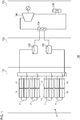
- Fig. 1 is a diagram to explain a solar thermal power generation system 100 according to an embodiment of the present invention.
- the solar thermal power generation system 100 includes a light collection area 121, a heat storage area 122, and a power generation area 123.
- the light collection area 121 is comprised mainly of a solar thermal collector 8.
- the solar thermal collector 8 is provided with a heat medium channel 11 comprised of a plurality of heat-collecting tubes in which the heat medium is caused to flow, and a plurality of reflecting plates 13 that collect sunlight to the heat-collecting tubes so as to heat the heat medium.
- the heated heat medium is delivered to the heat storage area 122.
- the heat storage area 122 is comprised mainly of a hot tank 102 and a cold tank 103. Storing the heat of the heated heat medium in the hot tank 102 enables generating electric power when it is necessary. For example, it will be possible to generate electric power at night or when the weather is bad during the day.
- the power generation area 123 includes a steam generator 104, a steam turbine generator 106, and a steam condenser 108.
- the steam generator 104 generates a steam by exchanging heat between the cooling water and the heated heat medium, and the steam turbine generator 106 rotates the turbine with the steam. The rotation generates electric power.
- the steam condenser 108 returns the steam into the cooling water.
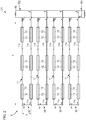
- Fig. 2 is a diagram to explain the solar thermal collector 8 according to the embodiment of the present invention.
- the solar thermal collector 8 includes a plurality of (4 in the case of Fig. 1 ) light collecting units 10 and a connecting channel 50.
- Each light condensing unit 10 includes a heat medium channel 11 and a plurality of reflecting plates 13.
- Each heat medium channel 11 is formed in a U shape and is comprised of long straight parts 11a and 11b parallel to each other, and a short straight part 11c connecting ends of the long straight parts 11a and 11b.
- Each of the long straight parts 11a and 11b is comprised of a plurality of heat collecting tubes 12 arranged in a straight line.
- the short straight part 11c is comprised of a connecting pipe 14.
- the length A of each of the long straight parts 11a, 11b may be about 100 ⁇ 200 m.
- the length of each of the heat collecting tubes 12 may be about 10 ⁇ 20 m.
- the long straight part 11a may be comprised of 10 ⁇ 20 heat collecting tubes 12.
- the length of the short straight part 11c may be 20 ⁇ 30 mm.
- Molten salt as a heat medium to receive solar heat flows in the heat collecting tubes 12 in the heat medium channel 11.
- Molten heat has a higher boiling point than synthetic oil used in solar-thermal collectors in the related art and so can be heated to a higher temperature. This increases the power generation efficiency of the solar thermal power generation system 100.
- molten salt is solidified at about 250°C. During an operation, molten salt is heated by the solar heat and so is not basically solidified. If the temperature of the heat collecting tubes 12 is relatively low when molten salt is run into the heat collecting tubes 12 at a startup or after a maintenance activity, however, the molten salt could be deprived of heat by the heat collecting tubes 12 and solidified. This embodiment addresses this by preheating the heat collecting tubes 12 to a predetermined temperature or higher before running molten salt into the heat collecting tubes 12. The method of preheating the heat collecting tubes 12 will be described later.
- the connecting channel 50 is a circular channel and is connected to each heat medium channel 11.
- the connecting channel 50 is also connected to the hot tank 102 and the cold tank 103 of the heat storage area 122. Therefore, each heat medium channel 11 is connected to the hot tank 102 and the cold tank 103 via the connecting channel 50.
- the heat medium flows from the cold tank 103 into the connecting channel 50.
- the heat medium flowing in the connecting channel 50 is run to the long straight part 11a of each heat medium channel 11.
- the heat medium heated by passing through the heat collecting tubes 12 of the long straight part 11a flows into the long straight part 11b via the connecting pipe 14.
- the heat medium heated by passing through the heat collecting tubes 12 of the long straight part 11b returns to the connecting channel 50 and flows into the hot tank 102.
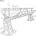
- Fig. 3 is a schematic perspective view to explain the solar thermal collector 8.
- the solar thermal collector 8 is provided with a stand 30 on the ground, and the heat collecting tube 12 and the reflecting plate 13 rotatably supported by the stand 30 around a rotational shaft 31.
- the solar thermal collector 8 is also provided with a rotating device that rotates the heat collecting tube 12 and the reflecting plate 13 around the rotational shaft 13 so as to follow the sun.
- the rotating device may be comprised of a hydraulic pump and a controller that controls the hydraulic pump.
- the reflecting plate 13 may be made from a highly reflective mirror or metal plate (e.g., steel plate or aluminum plate).
- a reflecting surface 13a of the reflecting plate 13 is formed with a parabolic-cylindrical surface. In other words, the cross section of the reflecting surface 13a vertical to the rotational shaft 31 is is parabolic.
- the heat collecting tube 12 is a tube that extends straight parallel to the rotational shaft 31.
- the heat collecting tube 12 is covered by a vacuum glass tube for heat insulation.
- the heat collecting tube 12 is supported such that the center thereof is located at the focal point of the parabolic reflecting plate 13 in a cross section vertical to the direction of extension of the heat collecting tube 12.
- the sunlight reflected by the reflecting surface 13a is collected at the focal point of the reflecting plate 13 so that the heat collecting tube 12 located at the focal point can be heated efficiently.
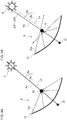
- Figs. 4A and 4B are diagrams to explain a method of preheating the heat-collecting tube 12 according to the embodiment of the present invention.
- Fig. 4A shows how the light is collected during a normal operation of heating the heat collecting tube 12 after a heat medium is introduced.
- the heat collecting tube 12 and the reflecting plate 13 are supported so as to be rotatable around the rotational shaft 13.
- the reflecting surface 13a of the reflecting plate 13 is formed to be parabolic in a cross section vertical to the rotational shaft 31.
- the heat collecting tube 12 is located at the focal point of the parabolic reflecting surface 13a. Assuming a hypothetical axis of symmetry As of the reflecting surface 13a of the reflecting plate 13, the heat collecting tube 12 is located on the axis of symmetry As. Rotation of the heat collecting tube 12 and the reflecting plate 13 is controlled by the rotating device (not shown).
- the rotating device rotates the heat collecting tube 12 and the reflecting plate 13 such that an angle ⁇ s of sunlight Ls from the sun S relative to the ground matches an angle ⁇ a of the axis of symmetry As of the reflecting plate 13 relative to the ground.
- This causes the heat collecting tube 12 and the reflecting plate 13 to be rotated to track the movement of the sun S.
- the sunlight Ls is collected in the heat collecting tube 12 located at the focal point of the parabolic reflecting surface 13a.
- Fig. 4B shows how the light is collected during preheating for heating the heat collecting tube 12 before a heat medium is introduced.
- the rotating device rotates the heat collecting tube 12 and the reflecting plate 13 during preheating such that the angle ⁇ s of the sunlight Ls and the angle ⁇ a of the axis of symmetry As of the reflecting plate 13 differ.
- the rotating device rotates the heat collecting tube 12 and the reflecting plate 13 such that an angle difference ⁇ between the angle ⁇ a of the axis of symmetry As and the angle ⁇ s of the sunlight Ls is equal to a predetermined angle difference ⁇ d. This rotates the heat collecting tube 12 and the reflecting plate 13 to follow the movement of the sun S with a delay of ⁇ d.
- the preheating method according to the embodiment only requires controlling the amount of rotation of the heat collecting tube 12 and the reflecting plate 13 and does not require adding other constituting elements. Thus, the method is much simpler and costs less than the method described above of inducing an electric current in the heat collecting tube for preheating.
- Fig. 5 is a graph showing an exemplary relationship between the angle difference and the light collection level ratio.
- the horizontal axis represents the angle difference ⁇ (°) between the angle ⁇ a of the axis of symmetry As and the angle ⁇ s of the sunlight Ls
- the vertical axis represents a light collection level ratio (%) with respect to the light collection level occurring when the the angle ⁇ a of the axis of symmetry As and the angle ⁇ s of the sunlight Ls are made to match.
- the optimum value of the predetermined angle difference ⁇ d can be determined based on the relationship between the angle difference and the light collection level ratio shown in Fig. 5 . If it is desired to set the light collection level ratio to 10%, for example, the angle difference ⁇ d may be set to about 1.2°.
- the light collection level ratio is preferably set to 5% ⁇ 20% and, more preferably, set to 8% ⁇ 12%.
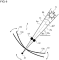
- Fig. 6 is a diagram to explain a method of preheating the heat collecting tube 12 according to another embodiment of the present invention.
- the angle difference ⁇ between the angle ⁇ a of the axis of symmetry As and the angle ⁇ s of the sunlight Ls is set to a fixed value.
- the rotating device rotates the heat collecting tube 12 and the reflecting plate 13, preheating the heat collecting tube 12, such that the angle difference ⁇ between the angle ⁇ s of the sunlight Ls and the angle ⁇ a of the axis of symmetry As of the reflecting plate 13 varies within a predetermined angular range ⁇ r.
- the rotating device swings the heat collecting tube 12 and the reflecting plate 13 such that the angle ⁇ a of the axis of symmetry As of the reflecting plate 13 varies by ⁇ r/2 around the angle ⁇ s of the sunlight Ls.
- the method of preheating the heat collecting tube 12 helps avoid the sunlight being collected only in a limited portion of the heat collecting tube 12 by swinging the the heat collecting tube 12 and the reflecting plate 13 and so can preheat the entirety of the heat collecting tube 12.
- the preheating method according to the embodiment also only requires controlling the amount of rotation of the heat collecting tube 12 and the reflecting plate 13 and does not require adding other constituting elements. Thus, the method is much simpler and costs less than the related-art method. It is preferable that the the heat collecting tube 12 and the reflecting plate 13 be swung at a period shorter than 10 seconds. In this case, the heat collecting tube 12 is suitably prevented from being excessively heated locally.
- the present invention can be used in solar thermal collectors used in solar thermal power generation systems.
Landscapes
- Engineering & Computer Science (AREA)
- Physics & Mathematics (AREA)
- Life Sciences & Earth Sciences (AREA)
- Sustainable Development (AREA)
- Sustainable Energy (AREA)
- Thermal Sciences (AREA)
- Chemical & Material Sciences (AREA)
- Combustion & Propulsion (AREA)
- Mechanical Engineering (AREA)
- General Engineering & Computer Science (AREA)
- Engine Equipment That Uses Special Cycles (AREA)
- Moulding By Coating Moulds (AREA)
Abstract

Description
- The present invention relates to a solar thermal collector that heats a heat medium flowing in a heat collecting tube by collecting sunlight.
- Solar thermal power generation systems are known that generate electric power by collecting sunlight to a heat collecting tube using a reflecting mirror so as to heat a heat medium flowing in the heat collecting tube, generating steam using the heated heat medium, and rotating a steam turbine. The cost of installing solar thermal power generation systems is lower than that of photovoltaic power generation systems. In addition, solar thermal power generation systems can generate electricity on a 24-hour basis by collecting heat. In the related art, solar thermal power generation systems that use oil as a heat medium are proposed (see, for example, patent document 1).
- Recently, molten salt has attracted attention as a heat medium for use in solar thermal power generation systems. Molten salt has a high boiling point. With the use of molten salt, the operating temperature can be relatively high and power generating efficiency is improved by generating high-temperature steam.
- Molten salt is solidified at about 250°C. If the temperature of the heat collecting tube is relatively low when molten salt is run into the heat collecting tube at a startup or after a maintenance activity, therefore, the molten salt is deprived of heat by the heat collecting tube and could be solidified. For this reason, it is necessary to preheat the heat-collecting tube to a predetermined temperature or higher before molten salt is run to the heat-collecting tube.
- One conceivable method to preheat the heat-collecting tube is to induce an electric current in the heat-collecting tube. By inducing an electric current, the Joule heat can warm the heat-collecting tube.
- [patent document 1]
JP2014-102013 - However, the preheating method described above of inducing an electric current in the heat-collecting tube has a drawback in that it requires an extremely large electric power and increases the cost.
- The present invention has been made in view of the foregoing circumstances, and a purpose of the invention is to provide a technology adapted for solar thermal collectors capable of preheating a heat-collecting tube at a low cost.
- In order to resolve the foregoing problems, a solar-thermal collector according to one embodiment of the present invention includes: a heat collecting tube in which a heat medium is caused to flow; a reflecting plate having a parabolic cross section that collects sunlight to the heat collecting tube; and a rotating device that rotates the heat collecting tube and the reflecting plate around a rotational shaft. The rotating device rotates the heat collecting tube and the reflecting plate, when preheating the heat collecting tube before the heat medium is introduced, such that an angle of the sunlight relative to the ground and an angle of an axis of symmetry of the reflecting plate relative to the ground are different.
- The rotating device may rotate the heat collecting tube and the reflecting plate, when preheating the heat collecting tube before the heat medium is introduced, such that an angle difference between the angle of the sunlight and the angle of the axis of symmetry of the reflecting plate differ is a predetermined angle difference.
- The rotating device may rotate the heat collecting tube and the reflecting plate, when preheating the heat collecting tube before the heat medium is introduced, such that an angle difference between the angle of the sunlight and the angle of the axis of symmetry of the reflecting plate differ varies within a predetermined angle range.
- Another embodiment of the present invention relates to a preheating method of a heat collecting tube included in a solar thermal collector in which a heat medium is caused to flow, the solar thermal collector further including a reflecting plate having a parabolic cross section that concentrates sunlight to the heat collecting tube. The preheating method includes: rotating the heat collecting tube and the reflecting plate such that an angle of the sunlight relative to the ground and an angle of an axis of symmetry of the reflecting plate relative to the ground are different; and condensing the sunlight to the heat collecting tube by using the reflecting plate.
- Optional combinations of the aforementioned constituting elements, and implementations of the invention in the form of methods, apparatuses, and systems may also be practiced as additional modes of the present invention.
- According to the present invention, the heat-collecting tube can be preheated at a low cost.
-
-
FIG. 1 is a diagram to explain a solar thermal power generation power system according to an embodiment of the present invention; -
Fig. 2 is a diagram to explain a solar thermal collector according to the embodiment of the present invention; -
Fig. 3 is a schematic perspective view to explain the solar thermal collector; -
Figs. 4A and 4B are diagrams to explain a method of preheating the heat-collecting tube according to the embodiment of the present invention; -
Fig. 5 is a graph showing an exemplary relationship between the angle difference and the light collection level ratio; and -
Fig. 6 is a diagram to explain a method of preheating the heat collecting tube according to another embodiment of the present invention. - The same or equivalent constituting elements and members shown in the drawings shall be denoted by the same reference numerals, and duplicative explanations will be omitted appropriately. The dimension of members in the drawings shall be enlarged or reduced as appropriate to facilitate understanding. Those of the members that are not material to the description of the embodiments are omitted in the drawings.
-
Fig. 1 is a diagram to explain a solar thermalpower generation system 100 according to an embodiment of the present invention. The solar thermalpower generation system 100 includes alight collection area 121, aheat storage area 122, and apower generation area 123. - The
light collection area 121 is comprised mainly of a solarthermal collector 8. The solarthermal collector 8 is provided with aheat medium channel 11 comprised of a plurality of heat-collecting tubes in which the heat medium is caused to flow, and a plurality of reflectingplates 13 that collect sunlight to the heat-collecting tubes so as to heat the heat medium. The heated heat medium is delivered to theheat storage area 122. - The
heat storage area 122 is comprised mainly of ahot tank 102 and acold tank 103. Storing the heat of the heated heat medium in thehot tank 102 enables generating electric power when it is necessary. For example, it will be possible to generate electric power at night or when the weather is bad during the day. - The
power generation area 123 includes asteam generator 104, asteam turbine generator 106, and asteam condenser 108. Thesteam generator 104 generates a steam by exchanging heat between the cooling water and the heated heat medium, and thesteam turbine generator 106 rotates the turbine with the steam. The rotation generates electric power. Thesteam condenser 108 returns the steam into the cooling water. -
Fig. 2 is a diagram to explain the solarthermal collector 8 according to the embodiment of the present invention. As shown inFig. 2 , the solarthermal collector 8 includes a plurality of (4 in the case ofFig. 1 )light collecting units 10 and a connectingchannel 50. Eachlight condensing unit 10 includes aheat medium channel 11 and a plurality of reflectingplates 13. - Each
heat medium channel 11 is formed in a U shape and is comprised of longstraight parts straight part 11c connecting ends of the longstraight parts straight parts heat collecting tubes 12 arranged in a straight line. The shortstraight part 11c is comprised of a connectingpipe 14. The length A of each of the longstraight parts heat collecting tubes 12 may be about 10∼20 m. The longstraight part 11a may be comprised of 10∼20heat collecting tubes 12. The length of the shortstraight part 11c may be 20∼30 mm. - Molten salt as a heat medium to receive solar heat flows in the
heat collecting tubes 12 in theheat medium channel 11. Molten heat has a higher boiling point than synthetic oil used in solar-thermal collectors in the related art and so can be heated to a higher temperature. This increases the power generation efficiency of the solar thermalpower generation system 100. Meanwhile, molten salt is solidified at about 250°C. During an operation, molten salt is heated by the solar heat and so is not basically solidified. If the temperature of theheat collecting tubes 12 is relatively low when molten salt is run into theheat collecting tubes 12 at a startup or after a maintenance activity, however, the molten salt could be deprived of heat by theheat collecting tubes 12 and solidified. This embodiment addresses this by preheating theheat collecting tubes 12 to a predetermined temperature or higher before running molten salt into theheat collecting tubes 12. The method of preheating theheat collecting tubes 12 will be described later. - The connecting
channel 50 is a circular channel and is connected to eachheat medium channel 11. The connectingchannel 50 is also connected to thehot tank 102 and thecold tank 103 of theheat storage area 122. Therefore, eachheat medium channel 11 is connected to thehot tank 102 and thecold tank 103 via the connectingchannel 50. The heat medium flows from thecold tank 103 into the connectingchannel 50. The heat medium flowing in the connectingchannel 50 is run to the longstraight part 11a of eachheat medium channel 11. The heat medium heated by passing through theheat collecting tubes 12 of the longstraight part 11a flows into the longstraight part 11b via the connectingpipe 14. The heat medium heated by passing through theheat collecting tubes 12 of the longstraight part 11b returns to the connectingchannel 50 and flows into thehot tank 102. -
Fig. 3 is a schematic perspective view to explain the solarthermal collector 8. As shown inFig. 3 , the solarthermal collector 8 is provided with astand 30 on the ground, and theheat collecting tube 12 and the reflectingplate 13 rotatably supported by thestand 30 around arotational shaft 31. The solarthermal collector 8 is also provided with a rotating device that rotates theheat collecting tube 12 and the reflectingplate 13 around therotational shaft 13 so as to follow the sun. The rotating device may be comprised of a hydraulic pump and a controller that controls the hydraulic pump. - The reflecting
plate 13 may be made from a highly reflective mirror or metal plate (e.g., steel plate or aluminum plate). A reflectingsurface 13a of the reflectingplate 13 is formed with a parabolic-cylindrical surface. In other words, the cross section of the reflectingsurface 13a vertical to therotational shaft 31 is is parabolic. Theheat collecting tube 12 is a tube that extends straight parallel to therotational shaft 31. Theheat collecting tube 12 is covered by a vacuum glass tube for heat insulation. Theheat collecting tube 12 is supported such that the center thereof is located at the focal point of the parabolic reflectingplate 13 in a cross section vertical to the direction of extension of theheat collecting tube 12. The sunlight reflected by the reflectingsurface 13a is collected at the focal point of the reflectingplate 13 so that theheat collecting tube 12 located at the focal point can be heated efficiently. -
Figs. 4A and 4B are diagrams to explain a method of preheating the heat-collectingtube 12 according to the embodiment of the present invention. -
Fig. 4A shows how the light is collected during a normal operation of heating theheat collecting tube 12 after a heat medium is introduced. As mentioned above, theheat collecting tube 12 and the reflectingplate 13 are supported so as to be rotatable around therotational shaft 13. The reflectingsurface 13a of the reflectingplate 13 is formed to be parabolic in a cross section vertical to therotational shaft 31. Theheat collecting tube 12 is located at the focal point of the parabolic reflectingsurface 13a. Assuming a hypothetical axis of symmetry As of the reflectingsurface 13a of the reflectingplate 13, theheat collecting tube 12 is located on the axis of symmetry As. Rotation of theheat collecting tube 12 and the reflectingplate 13 is controlled by the rotating device (not shown). - As shown in
Fig. 4A , the rotating device rotates theheat collecting tube 12 and the reflectingplate 13 such that an angle θs of sunlight Ls from the sun S relative to the ground matches an angle θa of the axis of symmetry As of the reflectingplate 13 relative to the ground. This causes theheat collecting tube 12 and the reflectingplate 13 to be rotated to track the movement of the sun S. As shown inFig. 4A , the sunlight Ls is collected in theheat collecting tube 12 located at the focal point of the parabolic reflectingsurface 13a. -
Fig. 4B shows how the light is collected during preheating for heating theheat collecting tube 12 before a heat medium is introduced. As shown inFig. 4B , the rotating device rotates theheat collecting tube 12 and the reflectingplate 13 during preheating such that the angle θs of the sunlight Ls and the angle θa of the axis of symmetry As of the reflectingplate 13 differ. The rotating device rotates theheat collecting tube 12 and the reflectingplate 13 such that an angle difference Δθ between the angle θa of the axis of symmetry As and the angle θs of the sunlight Ls is equal to a predetermined angle difference Δθd. This rotates theheat collecting tube 12 and the reflectingplate 13 to follow the movement of the sun S with a delay of Δθd. If the angle θa of the axis of symmetry As and the angle θs of the sunlight Ls is displaced by Δθd, only a portion of the reflected light from the reflectingsurface 13a is collected in theheat collecting tube 12, as shown inFig. 4B . - If substantially the entire reflected light reflected by the reflecting
surface 13a is collected in theheat collecting tube 12 by matching the angle θs of the sunlight Ls with the angle θa of the axis of symmetry As of the reflectingplate 13, as shown inFig. 4A , while the heat medium is not introduced in theheat collecting tube 12, theheat collecting tube 12 will reach an extremely high temperature due to a boil dry condition and might be damaged. By displacing the angle θa of the axis of symmetry As and the angle θs of the sunlight Ls by Δθd, the level of light collection in theheat collecting tube 12 is inhibited so that the temperature of theheat collecting tube 12 is prevented from becoming extremely high and theheat collecting tube 12 is prevented from being damaged. The preheating method according to the embodiment only requires controlling the amount of rotation of theheat collecting tube 12 and the reflectingplate 13 and does not require adding other constituting elements. Thus, the method is much simpler and costs less than the method described above of inducing an electric current in the heat collecting tube for preheating. -
Fig. 5 is a graph showing an exemplary relationship between the angle difference and the light collection level ratio. Referring toFig. 5 , the horizontal axis represents the angle difference Δθ(°) between the angle θa of the axis of symmetry As and the angle θs of the sunlight Ls, and the vertical axis represents a light collection level ratio (%) with respect to the light collection level occurring when the the angle θa of the axis of symmetry As and the angle θs of the sunlight Ls are made to match. - The optimum value of the predetermined angle difference Δθd can be determined based on the relationship between the angle difference and the light collection level ratio shown in
Fig. 5 . If it is desired to set the light collection level ratio to 10%, for example, the angle difference Δθd may be set to about 1.2°. The light collection level ratio is preferably set to 5%∼20% and, more preferably, set to 8%∼12%. -
Fig. 6 is a diagram to explain a method of preheating theheat collecting tube 12 according to another embodiment of the present invention. In the above-described preheating method, the angle difference Δθ between the angle θa of the axis of symmetry As and the angle θs of the sunlight Ls is set to a fixed value. According to this embodiment, however, the rotating device rotates theheat collecting tube 12 and the reflectingplate 13, preheating theheat collecting tube 12, such that the angle difference Δθ between the angle θs of the sunlight Ls and the angle θa of the axis of symmetry As of the reflectingplate 13 varies within a predetermined angular range θr. In other words, the rotating device swings theheat collecting tube 12 and the reflectingplate 13 such that the angle θa of the axis of symmetry As of the reflectingplate 13 varies by ±θr/2 around the angle θs of the sunlight Ls. - The method of preheating the
heat collecting tube 12 according to this embodiment helps avoid the sunlight being collected only in a limited portion of theheat collecting tube 12 by swinging the theheat collecting tube 12 and the reflectingplate 13 and so can preheat the entirety of theheat collecting tube 12. The preheating method according to the embodiment also only requires controlling the amount of rotation of theheat collecting tube 12 and the reflectingplate 13 and does not require adding other constituting elements. Thus, the method is much simpler and costs less than the related-art method. It is preferable that the theheat collecting tube 12 and the reflectingplate 13 be swung at a period shorter than 10 seconds. In this case, theheat collecting tube 12 is suitably prevented from being excessively heated locally. - Described above is an explanation based on an exemplary embodiment. The embodiment is intended to be illustrative only and it will be understood by those skilled in the art that various modifications to constituting elements and processes could be developed and that such modifications are also within the scope of the present invention.
- 8 solar thermal collector, 10 light collecting unit, 11 heat medium channel, 12 heat collecting tube, 13 reflecting plate, 30 stand, 31 rotational shaft, 100 solar thermal power generation system
- The present invention can be used in solar thermal collectors used in solar thermal power generation systems.
Claims (4)
- A solar thermal collector comprising:a heat collecting tube in which a heat medium is caused to flow;a reflecting plate having a parabolic cross section that concentrates sunlight to the heat collecting tube; anda rotating device that rotates the heat collecting tube and the reflecting plate around a rotational shaft, whereinthe rotating device rotates the heat collecting tube and the reflecting plate, when preheating the heat collecting tube before the heat medium is introduced, such that an angle of the sunlight relative to the ground and an angle of an axis of symmetry of the reflecting plate relative to the ground are different.
- The solar thermal collector according to claim 1, wherein
the rotating device rotates the heat collecting tube and the reflecting plate, when preheating the heat collecting tube before the heat medium is introduced, such that an angle difference between the angle of the sunlight and the angle of the axis of symmetry of the reflecting plate differ is a predetermined angle difference. - The solar thermal collector according to claim 1, wherein
the rotating device rotates the heat collecting tube and the reflecting plate, when preheating the heat collecting tube before the heat medium is introduced, such that an angle difference between the angle of the sunlight and the angle of the axis of symmetry of the reflecting plate differ varies within a predetermined angle range. - A preheating method of a heat collecting tube comprised in a solar thermal collector in which a heat medium is caused to flow, the solar thermal collector further comprising a reflecting plate having a parabolic cross section that concentrates sunlight to the heat collecting tube, the preheating method comprising:rotating the heat collecting tube and the reflecting plate such that an angle of the sunlight relative to the ground and an angle of an axis of symmetry of the reflecting plate relative to the ground are different; andcondensing the sunlight to the heat collecting tube by using the reflecting plate.
Applications Claiming Priority (1)
| Application Number | Priority Date | Filing Date | Title |
|---|---|---|---|
| PCT/JP2015/065272 WO2016189703A1 (en) | 2015-05-27 | 2015-05-27 | Solar heat collection device and preheating method of heat collection tube |
Publications (2)
| Publication Number | Publication Date |
|---|---|
| EP3306224A1 true EP3306224A1 (en) | 2018-04-11 |
| EP3306224A4 EP3306224A4 (en) | 2018-12-26 |
Family
ID=57392644
Family Applications (1)
| Application Number | Title | Priority Date | Filing Date |
|---|---|---|---|
| EP15893337.4A Withdrawn EP3306224A4 (en) | 2015-05-27 | 2015-05-27 | Solar heat collection device and preheating method of heat collection tube |
Country Status (3)
| Country | Link |
|---|---|
| EP (1) | EP3306224A4 (en) |
| CN (1) | CN107969146A (en) |
| WO (1) | WO2016189703A1 (en) |
Family Cites Families (10)
| Publication number | Priority date | Publication date | Assignee | Title |
|---|---|---|---|---|
| JPS5912253A (en) * | 1982-07-13 | 1984-01-21 | Sanyo Electric Co Ltd | Solar heat collector |
| CN2516905Y (en) * | 2002-01-15 | 2002-10-16 | 葛贤育 | Fixed focusing solar heat collect heating device |
| US7055519B2 (en) * | 2003-12-10 | 2006-06-06 | United Technologies Corporation | Solar collector and method |
| CN201037705Y (en) * | 2006-04-05 | 2008-03-19 | 北京天瑞星真空技术开发有限公司 | Light gathering type solar energy heat collector |
| ITTO20070088U1 (en) * | 2007-07-04 | 2009-01-05 | Febo S R L | PROJECT S.I.P. SOLAR PRODUCTION SYSTEM |
| JP5687043B2 (en) * | 2010-12-13 | 2015-03-18 | 株式会社日立製作所 | Solar collector |
| US8763601B2 (en) * | 2011-12-29 | 2014-07-01 | Sulas Industries, Inc. | Solar tracker for solar energy devices |
| CN102563280A (en) * | 2012-02-29 | 2012-07-11 | 江苏太阳宝新能源有限公司 | Preheating and solidification prevention method for solar-thermal power generation molten salt energy-storage transmission pipeline |
| JP2013228184A (en) * | 2012-03-26 | 2013-11-07 | Ricoh Co Ltd | Linear solar concentrator and solar concentration power generation system |
| JP5868809B2 (en) * | 2012-08-06 | 2016-02-24 | 株式会社東芝 | Power plant and heat supply method |
-
2015
- 2015-05-27 WO PCT/JP2015/065272 patent/WO2016189703A1/en not_active Ceased
- 2015-05-27 CN CN201580080395.3A patent/CN107969146A/en active Pending
- 2015-05-27 EP EP15893337.4A patent/EP3306224A4/en not_active Withdrawn
Also Published As
| Publication number | Publication date |
|---|---|
| CN107969146A (en) | 2018-04-27 |
| EP3306224A4 (en) | 2018-12-26 |
| WO2016189703A1 (en) | 2016-12-01 |
Similar Documents
| Publication | Publication Date | Title |
|---|---|---|
| EP3212925B1 (en) | Combined wind and solar power generating system | |
| EP2322796B1 (en) | Systems and apparatus relating to solar-thermal power generation | |
| CN102667363B (en) | Systems and methods for rejecting heat in a solar power collection system | |
| JP2007533950A (en) | Structure and method using a multi-system for generating electricity and desalting water | |
| US20130014508A1 (en) | Optimized Heliostat Aiming | |
| CN109341109B (en) | A photothermal storage system for auxiliary heating of the base soil of water conveyance channels in cold areas in winter | |
| Zourellis et al. | Optimizing efficiency of biomass—fired organic rankine cycle with concentrated solar power in Denmark | |
| KR101379445B1 (en) | Solr lightand heat hybrid collecting System having a solar tracker | |
| CN214665287U (en) | Double-shaft groove type solar heat collector and steam hot water system | |
| CN115654753A (en) | A low heat loss operation method for a line-focused heat collection system and its line-focused heat collection system | |
| MX2014006740A (en) | HYBRID SOLAR ENERGY RECOVERY SYSTEM. | |
| CN107367077A (en) | Groove type solar collecting system based on multiple reflections | |
| CN102865677A (en) | Dish solar heat utilization system | |
| CN219120790U (en) | A multi-energy complementary device for asphalt heating | |
| CN208652949U (en) | Heliostat tracks driving device, heliostat and tower solar-thermal generating system | |
| KR20210061819A (en) | Solar energy storage system having dual heat-collecting tubes using multiple heating medium oil | |
| CN209622921U (en) | The solar energy heat build-up heating installation of automatic tracing and time synchronization rotation is reflected in face | |
| CN207335204U (en) | A kind of adjustable minute surface concentrating solar boiler | |
| CN107709892B (en) | Heating system | |
| CN113137768A (en) | Double-shaft groove type solar heat collector and steam hot water system | |
| WO2016189703A1 (en) | Solar heat collection device and preheating method of heat collection tube | |
| EP3318817B1 (en) | Heater | |
| EP2636969A1 (en) | Solar collector having a multi-tube receiver, thermosolar plants that use said collector and method for operating said plants | |
| EP4007849A1 (en) | Hybrid electricity generation with solar concentrating and wind power | |
| JP2008286511A (en) | Solar energy water heater |
Legal Events
| Date | Code | Title | Description |
|---|---|---|---|
| STAA | Information on the status of an ep patent application or granted ep patent |
Free format text: STATUS: THE INTERNATIONAL PUBLICATION HAS BEEN MADE |
|
| PUAI | Public reference made under article 153(3) epc to a published international application that has entered the european phase |
Free format text: ORIGINAL CODE: 0009012 |
|
| STAA | Information on the status of an ep patent application or granted ep patent |
Free format text: STATUS: REQUEST FOR EXAMINATION WAS MADE |
|
| 17P | Request for examination filed |
Effective date: 20171206 |
|
| AK | Designated contracting states |
Kind code of ref document: A1 Designated state(s): AL AT BE BG CH CY CZ DE DK EE ES FI FR GB GR HR HU IE IS IT LI LT LU LV MC MK MT NL NO PL PT RO RS SE SI SK SM TR |
|
| AX | Request for extension of the european patent |
Extension state: BA ME |
|
| DAX | Request for extension of the european patent (deleted) | ||
| A4 | Supplementary search report drawn up and despatched |
Effective date: 20181123 |
|
| RIC1 | Information provided on ipc code assigned before grant |
Ipc: F24S 23/74 20180101ALI20181119BHEP Ipc: F24S 30/425 20180101AFI20181119BHEP Ipc: F24S 50/80 20180101ALI20181119BHEP |
|
| STAA | Information on the status of an ep patent application or granted ep patent |
Free format text: STATUS: EXAMINATION IS IN PROGRESS |
|
| 17Q | First examination report despatched |
Effective date: 20200407 |
|
| STAA | Information on the status of an ep patent application or granted ep patent |
Free format text: STATUS: THE APPLICATION IS DEEMED TO BE WITHDRAWN |
|
| 18D | Application deemed to be withdrawn |
Effective date: 20221201 |