EP3306160A1 - Adhesive transfer hose having a barrier layer and method of use - Google Patents
Adhesive transfer hose having a barrier layer and method of use Download PDFInfo
- Publication number
- EP3306160A1 EP3306160A1 EP17181351.2A EP17181351A EP3306160A1 EP 3306160 A1 EP3306160 A1 EP 3306160A1 EP 17181351 A EP17181351 A EP 17181351A EP 3306160 A1 EP3306160 A1 EP 3306160A1
- Authority
- EP
- European Patent Office
- Prior art keywords
- hot melt
- melt adhesive
- hose
- barrier layer
- layer
- Prior art date
- Legal status (The legal status is an assumption and is not a legal conclusion. Google has not performed a legal analysis and makes no representation as to the accuracy of the status listed.)
- Granted
Links
Images






Classifications
-
- F—MECHANICAL ENGINEERING; LIGHTING; HEATING; WEAPONS; BLASTING
- F16—ENGINEERING ELEMENTS AND UNITS; GENERAL MEASURES FOR PRODUCING AND MAINTAINING EFFECTIVE FUNCTIONING OF MACHINES OR INSTALLATIONS; THERMAL INSULATION IN GENERAL
- F16L—PIPES; JOINTS OR FITTINGS FOR PIPES; SUPPORTS FOR PIPES, CABLES OR PROTECTIVE TUBING; MEANS FOR THERMAL INSULATION IN GENERAL
- F16L11/00—Hoses, i.e. flexible pipes
- F16L11/04—Hoses, i.e. flexible pipes made of rubber or flexible plastics
- F16L11/12—Hoses, i.e. flexible pipes made of rubber or flexible plastics with arrangements for particular purposes, e.g. specially profiled, with protecting layer, heated, electrically conducting
- F16L11/127—Hoses, i.e. flexible pipes made of rubber or flexible plastics with arrangements for particular purposes, e.g. specially profiled, with protecting layer, heated, electrically conducting electrically conducting
-
- B—PERFORMING OPERATIONS; TRANSPORTING
- B32—LAYERED PRODUCTS
- B32B—LAYERED PRODUCTS, i.e. PRODUCTS BUILT-UP OF STRATA OF FLAT OR NON-FLAT, e.g. CELLULAR OR HONEYCOMB, FORM
- B32B1/00—Layered products having a non-planar shape
- B32B1/08—Tubular products
-
- B—PERFORMING OPERATIONS; TRANSPORTING
- B32—LAYERED PRODUCTS
- B32B—LAYERED PRODUCTS, i.e. PRODUCTS BUILT-UP OF STRATA OF FLAT OR NON-FLAT, e.g. CELLULAR OR HONEYCOMB, FORM
- B32B15/00—Layered products comprising a layer of metal
- B32B15/04—Layered products comprising a layer of metal comprising metal as the main or only constituent of a layer, which is next to another layer of the same or of a different material
- B32B15/08—Layered products comprising a layer of metal comprising metal as the main or only constituent of a layer, which is next to another layer of the same or of a different material of synthetic resin
- B32B15/085—Layered products comprising a layer of metal comprising metal as the main or only constituent of a layer, which is next to another layer of the same or of a different material of synthetic resin comprising polyolefins
-
- B—PERFORMING OPERATIONS; TRANSPORTING
- B32—LAYERED PRODUCTS
- B32B—LAYERED PRODUCTS, i.e. PRODUCTS BUILT-UP OF STRATA OF FLAT OR NON-FLAT, e.g. CELLULAR OR HONEYCOMB, FORM
- B32B15/00—Layered products comprising a layer of metal
- B32B15/14—Layered products comprising a layer of metal next to a fibrous or filamentary layer
-
- B—PERFORMING OPERATIONS; TRANSPORTING
- B32—LAYERED PRODUCTS
- B32B—LAYERED PRODUCTS, i.e. PRODUCTS BUILT-UP OF STRATA OF FLAT OR NON-FLAT, e.g. CELLULAR OR HONEYCOMB, FORM
- B32B15/00—Layered products comprising a layer of metal
- B32B15/18—Layered products comprising a layer of metal comprising iron or steel
-
- B—PERFORMING OPERATIONS; TRANSPORTING
- B32—LAYERED PRODUCTS
- B32B—LAYERED PRODUCTS, i.e. PRODUCTS BUILT-UP OF STRATA OF FLAT OR NON-FLAT, e.g. CELLULAR OR HONEYCOMB, FORM
- B32B15/00—Layered products comprising a layer of metal
- B32B15/20—Layered products comprising a layer of metal comprising aluminium or copper
-
- B—PERFORMING OPERATIONS; TRANSPORTING
- B32—LAYERED PRODUCTS
- B32B—LAYERED PRODUCTS, i.e. PRODUCTS BUILT-UP OF STRATA OF FLAT OR NON-FLAT, e.g. CELLULAR OR HONEYCOMB, FORM
- B32B23/00—Layered products comprising a layer of cellulosic plastic substances, i.e. substances obtained by chemical modification of cellulose, e.g. cellulose ethers, cellulose esters, viscose
- B32B23/04—Layered products comprising a layer of cellulosic plastic substances, i.e. substances obtained by chemical modification of cellulose, e.g. cellulose ethers, cellulose esters, viscose comprising such cellulosic plastic substance as the main or only constituent of a layer, which is next to another layer of the same or of a different material
- B32B23/08—Layered products comprising a layer of cellulosic plastic substances, i.e. substances obtained by chemical modification of cellulose, e.g. cellulose ethers, cellulose esters, viscose comprising such cellulosic plastic substance as the main or only constituent of a layer, which is next to another layer of the same or of a different material of synthetic resin
-
- B—PERFORMING OPERATIONS; TRANSPORTING
- B32—LAYERED PRODUCTS
- B32B—LAYERED PRODUCTS, i.e. PRODUCTS BUILT-UP OF STRATA OF FLAT OR NON-FLAT, e.g. CELLULAR OR HONEYCOMB, FORM
- B32B23/00—Layered products comprising a layer of cellulosic plastic substances, i.e. substances obtained by chemical modification of cellulose, e.g. cellulose ethers, cellulose esters, viscose
- B32B23/20—Layered products comprising a layer of cellulosic plastic substances, i.e. substances obtained by chemical modification of cellulose, e.g. cellulose ethers, cellulose esters, viscose comprising esters
-
- B—PERFORMING OPERATIONS; TRANSPORTING
- B32—LAYERED PRODUCTS
- B32B—LAYERED PRODUCTS, i.e. PRODUCTS BUILT-UP OF STRATA OF FLAT OR NON-FLAT, e.g. CELLULAR OR HONEYCOMB, FORM
- B32B27/00—Layered products comprising a layer of synthetic resin
- B32B27/06—Layered products comprising a layer of synthetic resin as the main or only constituent of a layer, which is next to another layer of the same or of a different material
- B32B27/08—Layered products comprising a layer of synthetic resin as the main or only constituent of a layer, which is next to another layer of the same or of a different material of synthetic resin
-
- B—PERFORMING OPERATIONS; TRANSPORTING
- B32—LAYERED PRODUCTS
- B32B—LAYERED PRODUCTS, i.e. PRODUCTS BUILT-UP OF STRATA OF FLAT OR NON-FLAT, e.g. CELLULAR OR HONEYCOMB, FORM
- B32B27/00—Layered products comprising a layer of synthetic resin
- B32B27/12—Layered products comprising a layer of synthetic resin next to a fibrous or filamentary layer
-
- B—PERFORMING OPERATIONS; TRANSPORTING
- B32—LAYERED PRODUCTS
- B32B—LAYERED PRODUCTS, i.e. PRODUCTS BUILT-UP OF STRATA OF FLAT OR NON-FLAT, e.g. CELLULAR OR HONEYCOMB, FORM
- B32B27/00—Layered products comprising a layer of synthetic resin
- B32B27/18—Layered products comprising a layer of synthetic resin characterised by the use of special additives
-
- B—PERFORMING OPERATIONS; TRANSPORTING
- B32—LAYERED PRODUCTS
- B32B—LAYERED PRODUCTS, i.e. PRODUCTS BUILT-UP OF STRATA OF FLAT OR NON-FLAT, e.g. CELLULAR OR HONEYCOMB, FORM
- B32B27/00—Layered products comprising a layer of synthetic resin
- B32B27/18—Layered products comprising a layer of synthetic resin characterised by the use of special additives
- B32B27/20—Layered products comprising a layer of synthetic resin characterised by the use of special additives using fillers, pigments, thixotroping agents
-
- B—PERFORMING OPERATIONS; TRANSPORTING
- B32—LAYERED PRODUCTS
- B32B—LAYERED PRODUCTS, i.e. PRODUCTS BUILT-UP OF STRATA OF FLAT OR NON-FLAT, e.g. CELLULAR OR HONEYCOMB, FORM
- B32B27/00—Layered products comprising a layer of synthetic resin
- B32B27/30—Layered products comprising a layer of synthetic resin comprising vinyl (co)polymers; comprising acrylic (co)polymers
- B32B27/302—Layered products comprising a layer of synthetic resin comprising vinyl (co)polymers; comprising acrylic (co)polymers comprising aromatic vinyl (co)polymers, e.g. styrenic (co)polymers
-
- B—PERFORMING OPERATIONS; TRANSPORTING
- B32—LAYERED PRODUCTS
- B32B—LAYERED PRODUCTS, i.e. PRODUCTS BUILT-UP OF STRATA OF FLAT OR NON-FLAT, e.g. CELLULAR OR HONEYCOMB, FORM
- B32B27/00—Layered products comprising a layer of synthetic resin
- B32B27/30—Layered products comprising a layer of synthetic resin comprising vinyl (co)polymers; comprising acrylic (co)polymers
- B32B27/304—Layered products comprising a layer of synthetic resin comprising vinyl (co)polymers; comprising acrylic (co)polymers comprising vinyl halide (co)polymers, e.g. PVC, PVDC, PVF, PVDF
-
- B—PERFORMING OPERATIONS; TRANSPORTING
- B32—LAYERED PRODUCTS
- B32B—LAYERED PRODUCTS, i.e. PRODUCTS BUILT-UP OF STRATA OF FLAT OR NON-FLAT, e.g. CELLULAR OR HONEYCOMB, FORM
- B32B27/00—Layered products comprising a layer of synthetic resin
- B32B27/32—Layered products comprising a layer of synthetic resin comprising polyolefins
- B32B27/322—Layered products comprising a layer of synthetic resin comprising polyolefins comprising halogenated polyolefins, e.g. PTFE
-
- B—PERFORMING OPERATIONS; TRANSPORTING
- B32—LAYERED PRODUCTS
- B32B—LAYERED PRODUCTS, i.e. PRODUCTS BUILT-UP OF STRATA OF FLAT OR NON-FLAT, e.g. CELLULAR OR HONEYCOMB, FORM
- B32B27/00—Layered products comprising a layer of synthetic resin
- B32B27/34—Layered products comprising a layer of synthetic resin comprising polyamides
-
- B—PERFORMING OPERATIONS; TRANSPORTING
- B32—LAYERED PRODUCTS
- B32B—LAYERED PRODUCTS, i.e. PRODUCTS BUILT-UP OF STRATA OF FLAT OR NON-FLAT, e.g. CELLULAR OR HONEYCOMB, FORM
- B32B27/00—Layered products comprising a layer of synthetic resin
- B32B27/36—Layered products comprising a layer of synthetic resin comprising polyesters
-
- B—PERFORMING OPERATIONS; TRANSPORTING
- B32—LAYERED PRODUCTS
- B32B—LAYERED PRODUCTS, i.e. PRODUCTS BUILT-UP OF STRATA OF FLAT OR NON-FLAT, e.g. CELLULAR OR HONEYCOMB, FORM
- B32B27/00—Layered products comprising a layer of synthetic resin
- B32B27/38—Layered products comprising a layer of synthetic resin comprising epoxy resins
-
- B—PERFORMING OPERATIONS; TRANSPORTING
- B32—LAYERED PRODUCTS
- B32B—LAYERED PRODUCTS, i.e. PRODUCTS BUILT-UP OF STRATA OF FLAT OR NON-FLAT, e.g. CELLULAR OR HONEYCOMB, FORM
- B32B27/00—Layered products comprising a layer of synthetic resin
- B32B27/42—Layered products comprising a layer of synthetic resin comprising condensation resins of aldehydes, e.g. with phenols, ureas or melamines
-
- B—PERFORMING OPERATIONS; TRANSPORTING
- B32—LAYERED PRODUCTS
- B32B—LAYERED PRODUCTS, i.e. PRODUCTS BUILT-UP OF STRATA OF FLAT OR NON-FLAT, e.g. CELLULAR OR HONEYCOMB, FORM
- B32B3/00—Layered products comprising a layer with external or internal discontinuities or unevennesses, or a layer of non-planar shape; Layered products comprising a layer having particular features of form
- B32B3/26—Layered products comprising a layer with external or internal discontinuities or unevennesses, or a layer of non-planar shape; Layered products comprising a layer having particular features of form characterised by a particular shape of the outline of the cross-section of a continuous layer; characterised by a layer with cavities or internal voids ; characterised by an apertured layer
- B32B3/28—Layered products comprising a layer with external or internal discontinuities or unevennesses, or a layer of non-planar shape; Layered products comprising a layer having particular features of form characterised by a particular shape of the outline of the cross-section of a continuous layer; characterised by a layer with cavities or internal voids ; characterised by an apertured layer characterised by a layer comprising a deformed thin sheet, i.e. the layer having its entire thickness deformed out of the plane, e.g. corrugated, crumpled
-
- B—PERFORMING OPERATIONS; TRANSPORTING
- B32—LAYERED PRODUCTS
- B32B—LAYERED PRODUCTS, i.e. PRODUCTS BUILT-UP OF STRATA OF FLAT OR NON-FLAT, e.g. CELLULAR OR HONEYCOMB, FORM
- B32B5/00—Layered products characterised by the non- homogeneity or physical structure, i.e. comprising a fibrous, filamentary, particulate or foam layer; Layered products characterised by having a layer differing constitutionally or physically in different parts
- B32B5/02—Layered products characterised by the non- homogeneity or physical structure, i.e. comprising a fibrous, filamentary, particulate or foam layer; Layered products characterised by having a layer differing constitutionally or physically in different parts characterised by structural features of a fibrous or filamentary layer
- B32B5/024—Woven fabric
-
- B—PERFORMING OPERATIONS; TRANSPORTING
- B32—LAYERED PRODUCTS
- B32B—LAYERED PRODUCTS, i.e. PRODUCTS BUILT-UP OF STRATA OF FLAT OR NON-FLAT, e.g. CELLULAR OR HONEYCOMB, FORM
- B32B5/00—Layered products characterised by the non- homogeneity or physical structure, i.e. comprising a fibrous, filamentary, particulate or foam layer; Layered products characterised by having a layer differing constitutionally or physically in different parts
- B32B5/22—Layered products characterised by the non- homogeneity or physical structure, i.e. comprising a fibrous, filamentary, particulate or foam layer; Layered products characterised by having a layer differing constitutionally or physically in different parts characterised by the presence of two or more layers which are next to each other and are fibrous, filamentary, formed of particles or foamed
- B32B5/24—Layered products characterised by the non- homogeneity or physical structure, i.e. comprising a fibrous, filamentary, particulate or foam layer; Layered products characterised by having a layer differing constitutionally or physically in different parts characterised by the presence of two or more layers which are next to each other and are fibrous, filamentary, formed of particles or foamed one layer being a fibrous or filamentary layer
- B32B5/26—Layered products characterised by the non- homogeneity or physical structure, i.e. comprising a fibrous, filamentary, particulate or foam layer; Layered products characterised by having a layer differing constitutionally or physically in different parts characterised by the presence of two or more layers which are next to each other and are fibrous, filamentary, formed of particles or foamed one layer being a fibrous or filamentary layer another layer next to it also being fibrous or filamentary
-
- B—PERFORMING OPERATIONS; TRANSPORTING
- B32—LAYERED PRODUCTS
- B32B—LAYERED PRODUCTS, i.e. PRODUCTS BUILT-UP OF STRATA OF FLAT OR NON-FLAT, e.g. CELLULAR OR HONEYCOMB, FORM
- B32B7/00—Layered products characterised by the relation between layers; Layered products characterised by the relative orientation of features between layers, or by the relative values of a measurable parameter between layers, i.e. products comprising layers having different physical, chemical or physicochemical properties; Layered products characterised by the interconnection of layers
- B32B7/04—Interconnection of layers
-
- F—MECHANICAL ENGINEERING; LIGHTING; HEATING; WEAPONS; BLASTING
- F16—ENGINEERING ELEMENTS AND UNITS; GENERAL MEASURES FOR PRODUCING AND MAINTAINING EFFECTIVE FUNCTIONING OF MACHINES OR INSTALLATIONS; THERMAL INSULATION IN GENERAL
- F16L—PIPES; JOINTS OR FITTINGS FOR PIPES; SUPPORTS FOR PIPES, CABLES OR PROTECTIVE TUBING; MEANS FOR THERMAL INSULATION IN GENERAL
- F16L11/00—Hoses, i.e. flexible pipes
- F16L11/04—Hoses, i.e. flexible pipes made of rubber or flexible plastics
- F16L11/08—Hoses, i.e. flexible pipes made of rubber or flexible plastics with reinforcements embedded in the wall
-
- F—MECHANICAL ENGINEERING; LIGHTING; HEATING; WEAPONS; BLASTING
- F16—ENGINEERING ELEMENTS AND UNITS; GENERAL MEASURES FOR PRODUCING AND MAINTAINING EFFECTIVE FUNCTIONING OF MACHINES OR INSTALLATIONS; THERMAL INSULATION IN GENERAL
- F16L—PIPES; JOINTS OR FITTINGS FOR PIPES; SUPPORTS FOR PIPES, CABLES OR PROTECTIVE TUBING; MEANS FOR THERMAL INSULATION IN GENERAL
- F16L11/00—Hoses, i.e. flexible pipes
- F16L11/04—Hoses, i.e. flexible pipes made of rubber or flexible plastics
- F16L11/12—Hoses, i.e. flexible pipes made of rubber or flexible plastics with arrangements for particular purposes, e.g. specially profiled, with protecting layer, heated, electrically conducting
-
- H—ELECTRICITY
- H05—ELECTRIC TECHNIQUES NOT OTHERWISE PROVIDED FOR
- H05B—ELECTRIC HEATING; ELECTRIC LIGHT SOURCES NOT OTHERWISE PROVIDED FOR; CIRCUIT ARRANGEMENTS FOR ELECTRIC LIGHT SOURCES, IN GENERAL
- H05B3/00—Ohmic-resistance heating
- H05B3/40—Heating elements having the shape of rods or tubes
- H05B3/54—Heating elements having the shape of rods or tubes flexible
- H05B3/58—Heating hoses; Heating collars
-
- B—PERFORMING OPERATIONS; TRANSPORTING
- B32—LAYERED PRODUCTS
- B32B—LAYERED PRODUCTS, i.e. PRODUCTS BUILT-UP OF STRATA OF FLAT OR NON-FLAT, e.g. CELLULAR OR HONEYCOMB, FORM
- B32B2250/00—Layers arrangement
- B32B2250/05—5 or more layers
-
- B—PERFORMING OPERATIONS; TRANSPORTING
- B32—LAYERED PRODUCTS
- B32B—LAYERED PRODUCTS, i.e. PRODUCTS BUILT-UP OF STRATA OF FLAT OR NON-FLAT, e.g. CELLULAR OR HONEYCOMB, FORM
- B32B2255/00—Coating on the layer surface
- B32B2255/10—Coating on the layer surface on synthetic resin layer or on natural or synthetic rubber layer
-
- B—PERFORMING OPERATIONS; TRANSPORTING
- B32—LAYERED PRODUCTS
- B32B—LAYERED PRODUCTS, i.e. PRODUCTS BUILT-UP OF STRATA OF FLAT OR NON-FLAT, e.g. CELLULAR OR HONEYCOMB, FORM
- B32B2255/00—Coating on the layer surface
- B32B2255/20—Inorganic coating
- B32B2255/205—Metallic coating
-
- B—PERFORMING OPERATIONS; TRANSPORTING
- B32—LAYERED PRODUCTS
- B32B—LAYERED PRODUCTS, i.e. PRODUCTS BUILT-UP OF STRATA OF FLAT OR NON-FLAT, e.g. CELLULAR OR HONEYCOMB, FORM
- B32B2262/00—Composition or structural features of fibres which form a fibrous or filamentary layer or are present as additives
- B32B2262/02—Synthetic macromolecular fibres
- B32B2262/0261—Polyamide fibres
- B32B2262/0269—Aromatic polyamide fibres
-
- B—PERFORMING OPERATIONS; TRANSPORTING
- B32—LAYERED PRODUCTS
- B32B—LAYERED PRODUCTS, i.e. PRODUCTS BUILT-UP OF STRATA OF FLAT OR NON-FLAT, e.g. CELLULAR OR HONEYCOMB, FORM
- B32B2262/00—Composition or structural features of fibres which form a fibrous or filamentary layer or are present as additives
- B32B2262/10—Inorganic fibres
- B32B2262/101—Glass fibres
-
- B—PERFORMING OPERATIONS; TRANSPORTING
- B32—LAYERED PRODUCTS
- B32B—LAYERED PRODUCTS, i.e. PRODUCTS BUILT-UP OF STRATA OF FLAT OR NON-FLAT, e.g. CELLULAR OR HONEYCOMB, FORM
- B32B2262/00—Composition or structural features of fibres which form a fibrous or filamentary layer or are present as additives
- B32B2262/10—Inorganic fibres
- B32B2262/103—Metal fibres
-
- B—PERFORMING OPERATIONS; TRANSPORTING
- B32—LAYERED PRODUCTS
- B32B—LAYERED PRODUCTS, i.e. PRODUCTS BUILT-UP OF STRATA OF FLAT OR NON-FLAT, e.g. CELLULAR OR HONEYCOMB, FORM
- B32B2264/00—Composition or properties of particles which form a particulate layer or are present as additives
- B32B2264/10—Inorganic particles
- B32B2264/102—Oxide or hydroxide
-
- B—PERFORMING OPERATIONS; TRANSPORTING
- B32—LAYERED PRODUCTS
- B32B—LAYERED PRODUCTS, i.e. PRODUCTS BUILT-UP OF STRATA OF FLAT OR NON-FLAT, e.g. CELLULAR OR HONEYCOMB, FORM
- B32B2264/00—Composition or properties of particles which form a particulate layer or are present as additives
- B32B2264/10—Inorganic particles
- B32B2264/104—Oxysalt, e.g. carbonate, sulfate, phosphate or nitrate particles
-
- B—PERFORMING OPERATIONS; TRANSPORTING
- B32—LAYERED PRODUCTS
- B32B—LAYERED PRODUCTS, i.e. PRODUCTS BUILT-UP OF STRATA OF FLAT OR NON-FLAT, e.g. CELLULAR OR HONEYCOMB, FORM
- B32B2264/00—Composition or properties of particles which form a particulate layer or are present as additives
- B32B2264/10—Inorganic particles
- B32B2264/105—Metal
-
- B—PERFORMING OPERATIONS; TRANSPORTING
- B32—LAYERED PRODUCTS
- B32B—LAYERED PRODUCTS, i.e. PRODUCTS BUILT-UP OF STRATA OF FLAT OR NON-FLAT, e.g. CELLULAR OR HONEYCOMB, FORM
- B32B2264/00—Composition or properties of particles which form a particulate layer or are present as additives
- B32B2264/12—Mixture of at least two particles made of different materials
-
- B—PERFORMING OPERATIONS; TRANSPORTING
- B32—LAYERED PRODUCTS
- B32B—LAYERED PRODUCTS, i.e. PRODUCTS BUILT-UP OF STRATA OF FLAT OR NON-FLAT, e.g. CELLULAR OR HONEYCOMB, FORM
- B32B2307/00—Properties of the layers or laminate
- B32B2307/30—Properties of the layers or laminate having particular thermal properties
- B32B2307/308—Heat stability
-
- B—PERFORMING OPERATIONS; TRANSPORTING
- B32—LAYERED PRODUCTS
- B32B—LAYERED PRODUCTS, i.e. PRODUCTS BUILT-UP OF STRATA OF FLAT OR NON-FLAT, e.g. CELLULAR OR HONEYCOMB, FORM
- B32B2307/00—Properties of the layers or laminate
- B32B2307/50—Properties of the layers or laminate having particular mechanical properties
-
- B—PERFORMING OPERATIONS; TRANSPORTING
- B32—LAYERED PRODUCTS
- B32B—LAYERED PRODUCTS, i.e. PRODUCTS BUILT-UP OF STRATA OF FLAT OR NON-FLAT, e.g. CELLULAR OR HONEYCOMB, FORM
- B32B2307/00—Properties of the layers or laminate
- B32B2307/50—Properties of the layers or laminate having particular mechanical properties
- B32B2307/546—Flexural strength; Flexion stiffness
-
- B—PERFORMING OPERATIONS; TRANSPORTING
- B32—LAYERED PRODUCTS
- B32B—LAYERED PRODUCTS, i.e. PRODUCTS BUILT-UP OF STRATA OF FLAT OR NON-FLAT, e.g. CELLULAR OR HONEYCOMB, FORM
- B32B2307/00—Properties of the layers or laminate
- B32B2307/70—Other properties
- B32B2307/714—Inert, i.e. inert to chemical degradation, corrosion
-
- B—PERFORMING OPERATIONS; TRANSPORTING
- B32—LAYERED PRODUCTS
- B32B—LAYERED PRODUCTS, i.e. PRODUCTS BUILT-UP OF STRATA OF FLAT OR NON-FLAT, e.g. CELLULAR OR HONEYCOMB, FORM
- B32B2307/00—Properties of the layers or laminate
- B32B2307/70—Other properties
- B32B2307/724—Permeability to gases, adsorption
- B32B2307/7242—Non-permeable
-
- B—PERFORMING OPERATIONS; TRANSPORTING
- B32—LAYERED PRODUCTS
- B32B—LAYERED PRODUCTS, i.e. PRODUCTS BUILT-UP OF STRATA OF FLAT OR NON-FLAT, e.g. CELLULAR OR HONEYCOMB, FORM
- B32B2307/00—Properties of the layers or laminate
- B32B2307/70—Other properties
- B32B2307/724—Permeability to gases, adsorption
- B32B2307/7242—Non-permeable
- B32B2307/7244—Oxygen barrier
-
- B—PERFORMING OPERATIONS; TRANSPORTING
- B32—LAYERED PRODUCTS
- B32B—LAYERED PRODUCTS, i.e. PRODUCTS BUILT-UP OF STRATA OF FLAT OR NON-FLAT, e.g. CELLULAR OR HONEYCOMB, FORM
- B32B2597/00—Tubular articles, e.g. hoses, pipes
-
- F—MECHANICAL ENGINEERING; LIGHTING; HEATING; WEAPONS; BLASTING
- F16—ENGINEERING ELEMENTS AND UNITS; GENERAL MEASURES FOR PRODUCING AND MAINTAINING EFFECTIVE FUNCTIONING OF MACHINES OR INSTALLATIONS; THERMAL INSULATION IN GENERAL
- F16L—PIPES; JOINTS OR FITTINGS FOR PIPES; SUPPORTS FOR PIPES, CABLES OR PROTECTIVE TUBING; MEANS FOR THERMAL INSULATION IN GENERAL
- F16L11/00—Hoses, i.e. flexible pipes
- F16L11/04—Hoses, i.e. flexible pipes made of rubber or flexible plastics
- F16L11/08—Hoses, i.e. flexible pipes made of rubber or flexible plastics with reinforcements embedded in the wall
- F16L11/085—Hoses, i.e. flexible pipes made of rubber or flexible plastics with reinforcements embedded in the wall comprising one or more braided layers
-
- F—MECHANICAL ENGINEERING; LIGHTING; HEATING; WEAPONS; BLASTING
- F16—ENGINEERING ELEMENTS AND UNITS; GENERAL MEASURES FOR PRODUCING AND MAINTAINING EFFECTIVE FUNCTIONING OF MACHINES OR INSTALLATIONS; THERMAL INSULATION IN GENERAL
- F16L—PIPES; JOINTS OR FITTINGS FOR PIPES; SUPPORTS FOR PIPES, CABLES OR PROTECTIVE TUBING; MEANS FOR THERMAL INSULATION IN GENERAL
- F16L11/00—Hoses, i.e. flexible pipes
- F16L11/04—Hoses, i.e. flexible pipes made of rubber or flexible plastics
- F16L2011/047—Hoses, i.e. flexible pipes made of rubber or flexible plastics with a diffusion barrier layer
-
- F—MECHANICAL ENGINEERING; LIGHTING; HEATING; WEAPONS; BLASTING
- F16—ENGINEERING ELEMENTS AND UNITS; GENERAL MEASURES FOR PRODUCING AND MAINTAINING EFFECTIVE FUNCTIONING OF MACHINES OR INSTALLATIONS; THERMAL INSULATION IN GENERAL
- F16L—PIPES; JOINTS OR FITTINGS FOR PIPES; SUPPORTS FOR PIPES, CABLES OR PROTECTIVE TUBING; MEANS FOR THERMAL INSULATION IN GENERAL
- F16L53/00—Heating of pipes or pipe systems; Cooling of pipes or pipe systems
- F16L53/30—Heating of pipes or pipe systems
- F16L53/35—Ohmic-resistance heating
- F16L53/38—Ohmic-resistance heating using elongate electric heating elements, e.g. wires or ribbons
Definitions
- the present disclosure is generally directed to adhesive transfer hoses, and more specifically, to adhesive transfer hoses having a barrier layer preventing or minimizing the ingress of air into a conduit of the hose.
- Hot melt adhesives which include conventional hot melt adhesives and reactive, moisture curing hot melt polyurethane adhesives ("hot melt PURs”), are routinely used in various applications where a stable surface-to-surface bond must be formed. Further, hot melt adhesives are used in securing a variety of both similar and dissimilar materials together in a mating relationship, such as wood, plastics, corrugated films, paper, carton stocks, metals, rigid polyvinylchlorides (PVCs), fabrics, leathers, and others. These adhesives are especially useful in applications where it is desirable to have the adhesive solidify rapidly after being melted and dispensed.
- hot melt adhesives typically a polymer, a tackifier, and a selection of other additives such as antioxidants, are mixed together to produce the adhesive. These materials tend to form bonds through their rapid solidification as they cool from a melted state and have the advantage of being relatively easy to apply.
- hot melt PURs an isocyanate terminated urethane polymer is produced through the polymerization of polyols and excess polyisocyanate compounds. Hot melt PURs cure (e.g., cross-link) in the presence of adventitious moisture.
- a solid form of the hot melt adhesive comes in various shapes and sizes and is supplied to a melter that includes a heated tank and/or a heated grid to produce molten hot melt adhesive.
- Solid hot melt adhesive can also be supplied in drums or barrels in which the adhesive is melted by the use of a platen. After heating, the molten adhesive is pumped through a heated hose that maintains the molten material at the required application temperature, to an applicator or dispenser, which is sometimes referred to as a dispensing "gun" or a gun module, comprising a valve and a nozzle.
- An exemplary heated hose is described in commonly owned U.S. Patent No. 6,738,566 , which is incorporated herein by reference in its entirety.
- thermoplastic adhesive a common problem with heated hoses is the resulting discoloration of the molten hot melt adhesive. Such discoloration may negatively affect the "pot life" of the hot melt adhesive, since the discoloration can indicate that the hot melt adhesive has degraded.
- "Pot life” as used herein is the maximum time at the system temperature before the adhesive starts to degrade, thus resulting in increased viscosity, charring and/or gelling. This could be especially problematic in systems requiring relatively low flow rates.
- the "pot life" of the molten adhesive can shorten if it stays within a heated hose for too long. Shortening the "pot life" of a thermoplastic adhesive may result in operational problems, such as filter clogging, and may further require cleaning of the hose after charring has occurred.
- Char is adhesive that has been blackened or burned, and can result from a variety of reasons, such as heating hot melt adhesive for too long and/or heating it at too-high of a temperature. Additionally, it has been observed that the introduction of oxygen into the hose is a main cause of charring of the hot melt adhesive.
- hot melt adhesives can be protected by certain additives, like antioxidants, hot melt adhesives should not be kept in the molten state for an extended period of time since they can break down. Thus, the effects of heat, time and oxidation begin to break down the adhesive.
- the adhesive's polymer chains form active sites that can combine to form gels which stick to the walls of hoses and crevices in melt tanks, forming an anchor that inhibits effective flow of the hot melt adhesive through the system.
- char can harden and break off into pieces that clog filters and spray nozzles.
- a major problem with char is that once it gets into a hot melt system, it is very difficult and sometimes impossible to flush out. Once char forms it can cause ongoing product quality problems, extensive maintenance issues and work stoppages. In some cases, the entire hot melt system may need to be taken apart and the components must be burned out in a burnout oven to completely remove the char. This process is very time-consuming and expensive. Therefore, it is desirable to prevent or reduce char formation before it can become a problem in the system.
- the inventors of the present disclosure have found that one way to prevent charring of the adhesive is by eliminating or minimizing ingress of oxygen within the hose.
- preventing or reducing the introduction of oxygen into conventional adhesive transfer hoses can pose substantial problems since typical hoses that are long and have a small diameter provide a large transfer area for a small amount of adhesive.
- the ingress of oxygen into the transfer hose is more likely than the ingress of oxygen into the adhesive melting tank.
- the adhesive can sit in a heated hose for a long duration of time and experience minimal discoloration as long as oxygen is prevented from entering the hose during transfer of the adhesive.
- conventional hot melt hoses do not take into account the impact of the partial pressure of oxygen on diffusion through a typical hose core.
- the antioxidant and degradation processes consume oxygen within the hose, creating a driving force for diffusion from the atmosphere, despite the fact that the hose may be hydraulically pressurized to several hundred psi.
- hoses that are used for high temperature applications of 500°F and above, such as for polymer processing are well beyond those required to sufficiently melt the solid form of adhesive to a molten flowable state.
- discoloration and associated degradation of the hot melt adhesive are the result of adventitious oxygen that penetrates into and/or through the layers of the hot melt adhesive transfer hose and reacts with the hot melt adhesive under the molten temperature conditions. Accordingly, there is a need for a hot melt adhesive transfer hose having an impermeable barrier layer which serves to prevent or minimize the ingress of oxygen into the conduit of the hose that transfers the molten hot melt adhesive, thereby eliminating or at least greatly reducing the discoloration and corresponding charring of the molten hot melt adhesive during its residence time in the heated hose.
- a multi-layered hot melt adhesive transfer hose comprises a conduit for transporting heated liquid hot melt adhesive, an impermeable barrier layer configured to prevent the ingress of oxygen into a conduit of the hose that transports a molten hot melt adhesive; and at least one structural layer overlaying an exterior surface of the barrier layer and configured to withstand a high fluid pressure. More particularly, the barrier layer is configured to prevent ingress of oxygen from passing through the conduit and into the hot melt adhesive.
- a heater may also be provided for maintaining the hot melt adhesive at a set point temperature, wherein the heater is adapted to be electrically coupled to a power source controlled to maintain the set point to about 450°F or less for an extended period of time.
- the barrier layer and the structural layer each comprise a thermally stable material. Further, the barrier layer prevents the hot melt adhesive from charring when the adhesive is heated to about 450°F or less for an extended period of time.
- the barrier layer is a flexible metal tube that can include a plurality of seamless corrugations.
- the barrier layer may be a metal tape, such as aluminum tape.
- the at least one structural layer can include a braided jacket, which may be stainless steel.
- the flexible metal tube may also be stainless steel.
- the at least one structural layer can include two overlapping braided jackets, and an outer covering layer has a distinct multi-layered structure overlaying an exterior surface of the at least one structural layer.
- the outer covering layer can include a heating wire sublayer, an insulation sublayer covering the heating wire sublayer, and a protective sublayer covering the insulation sublayer. It should be appreciated that the outer covering layer can alternatively include a heating tape sublayer.
- the barrier layer may be a metallic coating applied to the inner tube.
- the flexible metal tube may include a liner disposed within.
- the liner comprises a heat stable polymeric material and is configured to improve flow of the molten hot melt adhesive through the flexible metal tube.
- the liner includes a smooth interior surface that facilitates fluid flow and prevents material incompatibility issues between the molten hot melt adhesive and the flexible metal tube.
- the barrier layer unexpectedly prevents the hot melt adhesive from discoloring and charring when the adhesive is heated at a temperature of about or greater than 250°F up to and including about 450°F for an extended period of time.
- a method of transporting hot melt adhesive including the step of transporting the hot melt adhesive at a temperature at or below about 450° F through a multi-layered transfer hose comprising a flexible metal tube forming an impermeable barrier layer configured to prevent the ingress of oxygen into a conduit of the hose.
- the flexible metal tube is heated to a temperature at or below about 450°F.
- the flexible metal tube can transport hot melt adhesive at a temperature at or below about 400° F.
- the flexible metal tube can transport hot melt adhesive at a temperature at or below about 350° F.
- barrier layer no significant discoloration and charring of the hot melt adhesive occurs when the adhesive remained inside the hose for at least twenty-four hours, at least forty-eight hours, seventy-two hours, or ninety-six hours.
- a multi-layered hot melt adhesive transfer hose wherein at least one of the layers is an oxygen barrier layer that prevents or minimizes the ingress of oxygen into a conduit of the hose that transports a molten hot melt adhesive.
- an apparatus for melting and dispensing a hot melt adhesive comprises a chamber for receiving a solid form of the hot melt adhesive; a heating device coupled to the chamber and configured to receive the hot melt adhesive for liquefying the solid form of the hot melt adhesive; and the multi-layered hot melt adhesive transfer hose fluidly coupled to the heating device.
- a method for dispensing hot melt adhesive such as a packaging grade hot melt adhesive.
- the method includes the steps of melting hot melt adhesive; transporting the melted hot melt adhesive through a hose to a dispenser; heating the melted hot melt adhesive in the hose at a set point temperature of about 450°F or less; preventing, with a barrier layer, the transfer of oxygen into the adhesive within the hose; and dispensing the hot melt adhesive onto a substrate.
- This method for dispensing hot melt adhesive produces no significant discoloration and charring of the adhesive when it remains inside the hose for at least 24 hours. Moreover, no significant discoloration and charring of the hot melt adhesive occur when the adhesive remains inside the hose for at least 48 hours to 96 hours.
- discoloration of the hot melt adhesive occurring in a conventional hot melt adhesive transfer hose may negatively affect the "pot life" of the hot melt adhesive by subsequently resulting in increased viscosity, charring, or gelling. It was observed that such discoloration could be derived from adventitious oxygen that had penetrated into and/or through the layers of the hot melt adhesive transfer hose and reacted with the hot melt adhesive under the molten temperature conditions.
- a multi-layered hot melt adhesive transfer hose that includes a barrier layer.
- the barrier layer serves to prevent or minimize the ingress of oxygen into the conduit of the hose that transfers the molten hot melt adhesive, and thereby reduces the discoloration of the molten hot melt adhesive. Further, the inhibition or reduction in oxygen ingress may also preserve the expected "pot life" of the hot melt adhesive.
- the oxygen barrier layer may be a distinct layer of the hose, or a composite or mixture of a heat stable polymer and an inorganic additive that functions as the inner tube, as will be explained in more detail below.
- a hot melt adhesive apparatus that incorporates one or more of the multi-layered hot melt adhesive transfer hoses, as well as a method for transferring hot melt adhesive and making the hot melt adhesive transfer hose, are also described.
- the barrier layer is impermeable and thus prevents oxygen from diffusing into the conduit of the hose.
- the oxygen barrier layer provides a level of oxygen permeability to the hot melt adhesive transfer hose that is low enough to reduce the discoloration as compared to one void of the oxygen barrier layer.
- the oxygen permeability of the hose with the oxygen barrier layer may be reduced by a factor of about 10 or about 100 or about 1,000 or more.
- a simplified multi-layered hot melt adhesive transfer hose 100 of the prior art is shown having an inner tube 102 for conveying the molten hot melt adhesive, a structural layer 104 for strength and protection, and an outer covering 106.
- the inner tube 102 forms the operative core of the hose 100 through which the molten hot melt adhesive actually flows.
- the inner tube 102 is made from a polymeric material capable of withstanding relatively high temperatures such as polytetraflouroethylene (PTFE). Since PTFE or other similar high melting temperature polymers are typically unable to withstand the high fluid pressure used to transfer the molten hot melt adhesive, the inner tube 102 needs to be reinforced by a reinforcing layer, or structural layer 104.
- PTFE polytetraflouroethylene
- the structural layer 104 which is disposed about the exterior of the inner tube 102 and serves to provide strength and protection to the inner tube 102, may comprise a braided jacket of thermally stable material.
- hot melt adhesives are heated to set point temperatures sufficient to melt the solid form to a molten, flowable state, which are generally in a range from about 100°C (about 212°F) to about 230°C (about 450°F).
- the hot melt adhesive transfer hose may experience pressures up to about 1500 psi (about 10.3 MPa) operating pressures. Accordingly, the structural layer 104 serves to provide desired physical integrity of the hot melt adhesive transfer hose.
- an oxygen barrier layer 203 of the hot melt adhesive transfer hose 200 may be a distinct layer that is in contact with an inner surface of the inner tube 102, which is in turn covered by the structural layer 104 and the outer covering 106.
- the oxygen barrier layer 203 may be a distinct layer that is in contact with an outer surface of the inner tube 102 or an inner surface of the structural layer 104, which in turn is covered by the outer covering 106.
- FIGS. 3A and 3B the oxygen barrier layer 203 may be a distinct layer that is in contact with an outer surface of the inner tube 102 or an inner surface of the structural layer 104, which in turn is covered by the outer covering 106.
- the oxygen barrier layer 203 may be a distinct layer that is circumferentially outside of the inner tube 102 and in contact with an outer surface of the structural layer 104 or an inner surface of the outer covering 106. As shown in FIGS. 5A and 5B , the oxygen barrier layer 203 may encompass the inner tube 102, the structural layer 104, and the outer covering 106, and is formed as a distinct layer that is in contact with an outer surface of the outer covering 106.
- the inner tube 102 forms the operative core of the hose 200 through which the molten hot melt adhesive actually flows.
- the oxygen barrier layer 203 may include a polymeric material, a metallic material, or a combination thereof. The selection of the material may be dependent upon the location of the oxygen barrier layer in the hot melt adhesive transfer hose.
- the inner tube 102, the structural layer 104, and/or the heat tape sublayer are in what may be referred to as a "hot zone," which is near or above the temperature of the molten hot melt adhesive.
- the outer surface of an insulation or the protective sublayers of the outer layer 106 are radially disposed from and are outside the hot zone, and thus are at a lower temperature. Accordingly, materials having melting temperatures above the desired working temperature of the molten hot melt adhesive may be used in constructing the oxygen barrier layer within or outside of the hot zone.
- the melting point of the material constructing the oxygen barrier layer 203 should have a melting point sufficiently above the desired working temperature of the molten hot melt adhesive.
- the melting point of the material constructing the oxygen barrier layer 203 within the hot zone is preferably above the desired working temperature of the molten hot melt adhesive by at least about 50°F or more, or about 100°F or more, or 200°F or more.
- materials having a sufficiently high melting point include, but are not limited to, metallic materials such as metal foils or metal coatings.
- Non-limiting examples of the metallic materials include an aluminum foil backed tape, or a metal or metallic coating applied by sputtering, chemical vapor deposition (CVD), plasma-enhanced chemical vapor deposition (PECVD), or atomic layer deposition (ALD).
- the surface of the layer onto which the metal or metallic coating is applied may be modified to improve metal adhesion, such as that described in U.S. Patent No. 6,420,041 , which is incorporated by reference herein in its entirety.
- the thicknesses of the metal materials useful for forming the oxygen barrier layer may vary depending on the desired level of reduction in oxygen permeability.
- the melting point of the polymeric materials may render the placement of the oxygen barrier layer 203 according to the placement depicted in one of FIGS. 2-5 more preferable over another.
- a list of exemplary polymeric materials having desirable oxygen permeability values is shown in Table 1: TABLE 1: Gas Permeability of Select Polymers Polymer Abbreviation, Product Name, etc.
- Oxygen permeability (cc / cm 2 / mm / sec / cmHg x 10 10) Polytetrafluoroethylene PTFE, TeflonTM - Perfluoro ethylenepropylene copolymer FEP 59 Polyvinylidene chloride PVDC, SaranTM 0.05 Polyvinyl Fluoride PVF, Tedlar® 0.2 Polyethylene terephthalate PET 0.3 Polychlorotrifluoroethylene PCTFE 0.25-5.4 Phenol resin PF, Bakelite® - Polyamide PA, Nylon 0.38 Epoxy resin EP 0.49-16 Polystyrene methacrylonitrile PS-MAN 1.6 Polyacetal (homopolymer) POM 0.38 Polyvinyl chloride PCV 1.2-6 Styrene-acrylonitrile - 3.4 Cellulose acetate CA 4.0-7.8 *** Table obtained from http://junkosha.co.jp/technical/tec8.html, which was adapted from Teflon®
- the polymeric material may comprise a urethane, such as a thermoplastic polyether-urethane (TPEU) or thermoplastic polyester-polyurethane elastomer, as disclosed in U.S. Patent No. 9,192,754 .
- TPEU thermoplastic polyether-urethane
- thermoplastic polyester-polyurethane elastomer as disclosed in U.S. Patent No. 9,192,754 .
- the polymeric material may also be combined with an inorganic additive, such as clays, silicates and silicas, pillared materials, metal salts, nanoplatelets, or mixtures thereof, such as those described in U.S. Patent Application Publication No. 2010/0300571 , which is incorporated herein by reference in its entirety.
- an inorganic additive such as clays, silicates and silicas, pillared materials, metal salts, nanoplatelets, or mixtures thereof, such as those described in U.S. Patent Application Publication No. 2010/0300571 , which is incorporated herein by reference in its entirety.
- lamellar nanofillers to the polymeric material matrix.
- Such a reduction in permeability may be attributed to an effect of "tortuousness" brought about by the lamellar nanofillers. This is because the oxygen has to follow a much longer pathway because of these obstacles arranged in successive strata.
- Theoretical models regard the barrier effects as becoming more pronounced as the aspect ratio,
- the lamellar nanofillers which are most widely investigated today are clays of smectite type, mainly montmorillonite.
- the difficulty of use lies first of all in the more or less extensive separation of these individual lamellae, that is to say the exfoliation, and in their distribution, in the polymer.
- an "intercalation” technique which consists in swelling the crystals with organic cations, generally quaternary ammonium cations, which will compensate for the negative charge of the lamellae.
- These crystalline aluminosilicates when they are exfoliated in a thermoplastic matrix, exist in the form of individual lamellae, the aspect ratio of which may reach values of the order of 500 or more.
- the inorganic additive may include particles based on zirconium, titanium, cerium and/or silicon phosphate, in the form of non-exfoliated nanometric lamellar compounds, as disclosed for example in U.S. Patent Application Publication No. 2007/0082159 , the relevant portions of which are hereby incorporated herein by reference.
- the inorganic additive content of the polymeric material used in constructing the oxygen barrier layer 203 may vary depending on the desired level of reduction in oxygen permeability.
- the inorganic additive may be present in the polymeric material in an amount from 0.01 % to about 50 % by weight with respect to the total weight of the oxygen barrier layer 203 composition.
- a barrier inner tube 608 which includes a combination of a polymeric material and one or more of the inorganic additives described above, may be used in constructing the hot melt adhesive transfer hose 600.
- the inorganic additive content of the polymeric material used in constructing the barrier inner tube 608 may vary depending on the desired level of reduction in oxygen permeability.
- the inorganic additive may be present in the polymeric material in an amount from 0.01 % to about 50 % by weight with respect to the total weight of the barrier inner tube 608 composition.
- the barrier inner tube 608 may comprise a fluoropolymer (e.g., polytetrafluoroethylene) in combination with a sufficient quantity of one or more of the inorganic additives described above to provide the desired level of reduction in oxygen permeability.
- a fluoropolymer e.g., polytetrafluoroethylene
- any airtight layer will expand and contract as the gases trapped within the insulation layers expand under the heat applied by the heating tape.
- the oxygen barrier layer 203 may be oversized and/or corrugated, or fitted with a one-way valve to allow the expansion gases to escape and subsequently blocks the ingress of oxygen.
- placement of the oxygen barrier layer 203 outside the hot zone further permits lower melting or softening materials to be used for this purpose.
- metalized polymer films e.g., aluminized mylar
- metalized polymer films may be used outside the hot zone, in addition to the higher melting materials discussed above.
- the transfer hose 600 shown in FIGS. 6A and 6B may also include a distinct oxygen barrier layer 203, such as that shown in FIGS. 2-5 . It should be further appreciated that while the oxygen barrier layer 203 or the barrier inner tube 608 may block or inhibit the ingress of oxygen into the conduit transporting the hot melt adhesive, it may be advantageous to utilize a low oxygen or inert gas atmosphere during the manufacture of the oxygen barrier layer 203, the barrier inner tube 608, and/or the hot melt adhesive transfer hose.
- FIG. 8 illustrates a qualitative color scale ranging from a base line of 1 (for an un-heated sample of Henkel 614C) to a maximum of 12 (for a sample heated for about 95 hours).
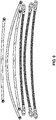
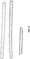
- Comparative testing Multiple samples were evaluated using different tubing with or without any oxygen barrier layers applied. As shown in FIG. 9 , different tubing types include 0.030" PTFE (Dupont Teflon® 62X resin based) core with or without stainless steel braid; 0.040" PTFE core with or without stainless steel braid; or 0.030" PTFE carbon-lined core with or without stainless steel braid. As shown in FIG. 10 , the tubing samples without stainless steel braid were sealed using black plastic screw caps. Multiples tubing and aluminum pan (“ratpan”) samples were prepared as described in Table 2 (below), and placed in a laboratory oven (see FIG. 11 ) and heated to 350°F for 29 hours. The samples were qualitatively evaluated using the developed color scale described above.
- the aluminum foil-wrapped PTFE inner tube (Sample 1c) provided an improvement in the discoloring of the molten hot melt adhesive under simulated testing conditions as compared to the uncoated PTFE tube (Sample 1a) or the silicone tape wrapped PTFE tube (Sample 1b). Although not shown, significant discoloring (e.g., 9 or higher) was still observed with the PTFE tubing that had an interior carbon coating. Further, it should be understood that in the event that color evaluation of the molten hot melt adhesive is to be monitored in-process, the equipment and methods described in commonly-assigned U.S. Patent Application Publication No. 2014/0144933 , which is expressly incorporated herein by reference in its entirety, may be utilized.
- a multi-layered hot melt adhesive transfer hose 700 configured to prevent air and other gasses from penetrating the hose and contacting the hot melt adhesive therein.
- the hot melt adhesive transfer hose 700 includes a barrier layer comprising an inner tube 702 configured to prevent the ingress of oxygen and other gases into the conduit of the hose, thereby eliminating discoloration and any associated degradation of the molten hot melt adhesive. Further, the prevention of oxygen passing into the hose also preserves the expected "pot life" of the hot melt adhesive.
- the inner tube 702 forms the operative core of the hose 700 through which the molten hot melt adhesive actually flows.
- the inner tube 702 is preferably made from a metallic material capable of withstanding relatively high temperatures such as stainless steel.
- the barrier layer can be a metal tape, such as aluminum, or a metallic coating applied to the core as will be discussed in greater detail below.
- the metal inner tube 702 of the hot melt adhesive hose 700 is gas impermeable, and therefore does not allow any air to diffuse into the conduit containing the hot melt adhesive.
- the barrier layer comprising the metal inner tube 702 prevents oxygen and other gasses from entering the hose and coming into contact with the hot melt adhesive, thereby eliminating charring.
- the metal inner tube 702 blocks moisture from affecting hot melt PURs, and can also keep gasses within the hose from escaping. For instance, foamed hot melt within the metal inner tube 702 maintains gas in solution longer than standard hoses. Moreover, manufacturing an imperviable flexible barrier layer comprising a metal inner tube according to the present disclosure is more time and cost efficient since existing hose manufacturing processes can be utilized and/or easily modified.
- the inner tube 702 has seamless corrugations to allow for flexibility, and preferably maintains a consistent tube wall thickness throughout the hose to minimize residual stress in the metal. Further, the inner tube 702 may be oversized.
- the inner tube 702 is reinforced by a reinforcing layer, or a structural layer 704 to help withstand the high fluid pressure used to transfer the molten hot melt adhesive.
- the structural layer 704, which is disposed about the exterior of the inner tube 702 and serves to provide added strength and protection to the inner tube, may comprise a braided jacket of thermally stable material.
- the structural layer 704 serves to provide desired physical integrity of the hot melt adhesive transfer hose.
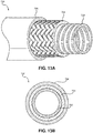
- the structural layer 704 includes a braided jacket made of stainless steel.
- the braiding frequency and/or thickness of the braid may vary depending on the expected temperature and pressure limits of the hot melt adhesive apparatus.
- the braid may be a spiral, a helical, woven/interwoven, or hoop/loop patterns such as square or single braids.
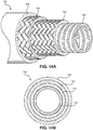
- the hose 700 can include a plurality of structural layers 704 to provide additional reinforcement for high pressure capability. As shown in FIG. 14 , a hose 700 having two overlapping structural layers 704, 705 is provided.
- the hot melt adhesive transfer hose 700 may comprise a liner 710 provided on an inner surface of the inner tube 702 as shown in FIGS. 15A and 15B .
- the liner 710 preferably comprises a heat stable polymeric material such as polytetrafluoroethylene (PTFE) or other polymer capable of withstanding relatively high temperatures.
- PTFE polytetrafluoroethylene
- the liner 710 is a distinct layer that is in contact with an inner surface of the corrugated inner tube 702.
- the liner is configured to improve flow of the hot melt adhesive by minimizing material incompatibility with the inner tube 702.
- the liner 710 has a smooth interior surface to facilitate fluid flow and prevent material incompatibility issues between the transferred media and the metal inner tube 702. For instance, the liner 710 prevents material from becoming lodged within grooves of the interior corrugations of the inner tube 702.
- the hose 700 may further comprise an outer covering 706.
- the outer covering 706 may be a multi-layered structure having a heating tape sublayer, an insulation sublayer, and/or a protective sublayer, which are not shown.
- the heating tape serves to provide uniform conduction heating to the hot melt adhesive hose.
- the insulation layer which may include but is not limited to aramid felt insulation or fiber glass insulation, serves to control heat loss and may also improve chemical and moisture resistance.
- the protective layer which principally serves to protect the hose and other inner component/layers from damage caused by physical abuse, may include, but is not limited to, a durable polymer such as aramid sheathing.
- Each sublayer of the outer covering is a separate and distinct layer.
- the heating tape sublayer is in contact with an outer surface of the structural layer 704 and is covered by the insulation sublayer.
- the protective sublayer covers the insulation sublayer.
- the inner tube 702, the structural layer 704, and/or the heat tape sublayer of the outer covering 706 are in what may be referred to as a "hot zone," which is near or above the temperature of the molten hot melt adhesive.
- a hot zone which is near or above the temperature of the molten hot melt adhesive.
- the outer surface of the insulation or the protective sublayers of the outer layer 706 are radially disposed from and are outside the hot zone, and are thus subjected to a lower temperature.
- the transfer hose 700 can be used in a hot melt system that includes a dispenser for dispensing hot melt adhesive onto a substrate.
- the hose 700 may be operatively coupled to the dispenser.
- the hose may also be operatively coupled to a source of liquid hot melt adhesive, such as a melter.
- the transfer hose can further include a heater for maintaining the hot melt adhesive at a set point.
- the heater can include at least one heating wire comprising metal such as copper, aluminum, or silver.
- the at least one heating wire may circumferentially wrap around an exterior surface of the inner core of the hose in a helical pattern.
- the at least one heating wire may be provided on an exterior surface of the inner core in a direction parallel to the longitudinal axis of the inner core.
- the heater is adapted to be electrically coupled to a power source controlled to maintain the set point to about 450°F or less for an extended period of time.
- the flexible metal tube may further transport the hot melt adhesive at a set point temperature at or below about 400° F, at a set point temperature at or below about 350° F, or at a set point temperature at or above about 250° F.
- a sensor can further be provided on the heater, or alternatively, within the hose, for measuring the set point temperature.
- the metal barrier layer 702 unexpectedly prevented the hot melt adhesive from charring within the hose 700 at certain temperatures for extended periods of time. Specifically, an unknown effect of the barrier layer 702 was observed, in which no charring of hot melt adhesive occurred for at least ninety-six hours when the adhesive was heated to a set point temperature in the range of about or greater than 250°F up to and including about 450°F.
- FIG. 16 an example of the observed discoloration over time of common hot melt adhesive (such as Technomelt® Supra 614C by Henkel) in a competitor's hot melt adhesive transfer hose is shown in line A, as compared to the observed discoloration over time of the hot melt adhesive in the transfer hose 700 of the present disclosure is shown in line B.
- the hot melt adhesive was maintained at a setpoint of 350°F in both the competitor's transfer hose and the present disclosure's transfer hose 700. Further, the color of the adhesive was observed every eight hours over a period of ninety-six total hours.
- the extent of discoloration of hot melt adhesive in the competitor's transfer hose increased greatly over time.
- the sample of adhesive A9 in the competitor's transfer hose at ninety-six hours was significantly discolored and contained a substantial amount of char.
- the sample of adhesive B9 in the transfer hose of the present disclosure at ninety-six hours was not significantly discolored and contained no significant amount of char formation.
- the sample of adhesive B9 in the transfer hose of the present disclosure at ninety-six hours had substantially the same color as the sample of adhesive B1 in the transfer hose of the present disclosure at startup.
- an unknown effect of the hose 700 is that there is no significant discoloration and charring of adhesive at 350°F within the hose at eight hours (B2), sixteen hours (B3), twenty-four hours (B4), thirty-two hours (B5), forty hours (B6), forty-eight hours (B7), seventy-two hours (B8) and ninety-six hours (B9).
- the metal barrier layer 702 unexpectedly resulted in less than 1.0% char formation at 24 hours.
- use of the metal barrier layer 702 unexpectedly resulted in less than 1.0% char formation at 48 hours, at 72 hours, and even at 96 hours, as shown in FIG. 16 .
- the adhesive inside the competitor's hose displayed significant discoloration and charring at eight hours (A2).
- the severity of discoloration and charring within the competitor's hose worsened at sixteen hours (A3), twenty-four hours (A4), thirty-two hours (A5), forty hours (A6), forty-eight hours (A7), seventy-two hours (A8), and ninety-six hours (A9).
Landscapes
- Engineering & Computer Science (AREA)
- General Engineering & Computer Science (AREA)
- Mechanical Engineering (AREA)
- Textile Engineering (AREA)
- Adhesives Or Adhesive Processes (AREA)
- Rigid Pipes And Flexible Pipes (AREA)
- Laminated Bodies (AREA)
- Pipe Accessories (AREA)
Abstract
Description
- This application claims the benefit of
U.S. Provisional Patent App. No. 62/363,138, filed July 15, 2016 - The present disclosure is generally directed to adhesive transfer hoses, and more specifically, to adhesive transfer hoses having a barrier layer preventing or minimizing the ingress of air into a conduit of the hose.
- Hot melt adhesives, which include conventional hot melt adhesives and reactive, moisture curing hot melt polyurethane adhesives ("hot melt PURs"), are routinely used in various applications where a stable surface-to-surface bond must be formed. Further, hot melt adhesives are used in securing a variety of both similar and dissimilar materials together in a mating relationship, such as wood, plastics, corrugated films, paper, carton stocks, metals, rigid polyvinylchlorides (PVCs), fabrics, leathers, and others. These adhesives are especially useful in applications where it is desirable to have the adhesive solidify rapidly after being melted and dispensed.
- In conventional hot melt adhesives, typically a polymer, a tackifier, and a selection of other additives such as antioxidants, are mixed together to produce the adhesive. These materials tend to form bonds through their rapid solidification as they cool from a melted state and have the advantage of being relatively easy to apply. In hot melt PURs, an isocyanate terminated urethane polymer is produced through the polymerization of polyols and excess polyisocyanate compounds. Hot melt PURs cure (e.g., cross-link) in the presence of adventitious moisture.
- Typically, a solid form of the hot melt adhesive comes in various shapes and sizes and is supplied to a melter that includes a heated tank and/or a heated grid to produce molten hot melt adhesive. Solid hot melt adhesive can also be supplied in drums or barrels in which the adhesive is melted by the use of a platen. After heating, the molten adhesive is pumped through a heated hose that maintains the molten material at the required application temperature, to an applicator or dispenser, which is sometimes referred to as a dispensing "gun" or a gun module, comprising a valve and a nozzle. An exemplary heated hose is described in commonly owned
U.S. Patent No. 6,738,566 , which is incorporated herein by reference in its entirety. - However, a common problem with heated hoses is the resulting discoloration of the molten hot melt adhesive. Such discoloration may negatively affect the "pot life" of the hot melt adhesive, since the discoloration can indicate that the hot melt adhesive has degraded. "Pot life" as used herein is the maximum time at the system temperature before the adhesive starts to degrade, thus resulting in increased viscosity, charring and/or gelling. This could be especially problematic in systems requiring relatively low flow rates. In some applications, the "pot life" of the molten adhesive can shorten if it stays within a heated hose for too long. Shortening the "pot life" of a thermoplastic adhesive may result in operational problems, such as filter clogging, and may further require cleaning of the hose after charring has occurred.
- Char is adhesive that has been blackened or burned, and can result from a variety of reasons, such as heating hot melt adhesive for too long and/or heating it at too-high of a temperature. Additionally, it has been observed that the introduction of oxygen into the hose is a main cause of charring of the hot melt adhesive. Although hot melt adhesives can be protected by certain additives, like antioxidants, hot melt adhesives should not be kept in the molten state for an extended period of time since they can break down. Thus, the effects of heat, time and oxidation begin to break down the adhesive. For instance, the adhesive's polymer chains form active sites that can combine to form gels which stick to the walls of hoses and crevices in melt tanks, forming an anchor that inhibits effective flow of the hot melt adhesive through the system. Moreover, char can harden and break off into pieces that clog filters and spray nozzles.
- A major problem with char is that once it gets into a hot melt system, it is very difficult and sometimes impossible to flush out. Once char forms it can cause ongoing product quality problems, extensive maintenance issues and work stoppages. In some cases, the entire hot melt system may need to be taken apart and the components must be burned out in a burnout oven to completely remove the char. This process is very time-consuming and expensive. Therefore, it is desirable to prevent or reduce char formation before it can become a problem in the system.
- The inventors of the present disclosure have found that one way to prevent charring of the adhesive is by eliminating or minimizing ingress of oxygen within the hose. However, preventing or reducing the introduction of oxygen into conventional adhesive transfer hoses can pose substantial problems since typical hoses that are long and have a small diameter provide a large transfer area for a small amount of adhesive. Thus, the ingress of oxygen into the transfer hose is more likely than the ingress of oxygen into the adhesive melting tank. For example, the adhesive can sit in a heated hose for a long duration of time and experience minimal discoloration as long as oxygen is prevented from entering the hose during transfer of the adhesive.
- Moreover, conventional hot melt hoses do not take into account the impact of the partial pressure of oxygen on diffusion through a typical hose core. The antioxidant and degradation processes consume oxygen within the hose, creating a driving force for diffusion from the atmosphere, despite the fact that the hose may be hydraulically pressurized to several hundred psi. Moreover, hoses that are used for high temperature applications of 500°F and above, such as for polymer processing, are well beyond those required to sufficiently melt the solid form of adhesive to a molten flowable state.
- Thus, discoloration and associated degradation of the hot melt adhesive are the result of adventitious oxygen that penetrates into and/or through the layers of the hot melt adhesive transfer hose and reacts with the hot melt adhesive under the molten temperature conditions. Accordingly, there is a need for a hot melt adhesive transfer hose having an impermeable barrier layer which serves to prevent or minimize the ingress of oxygen into the conduit of the hose that transfers the molten hot melt adhesive, thereby eliminating or at least greatly reducing the discoloration and corresponding charring of the molten hot melt adhesive during its residence time in the heated hose.
- A multi-layered hot melt adhesive transfer hose is provided. The transfer hose comprises a conduit for transporting heated liquid hot melt adhesive, an impermeable barrier layer configured to prevent the ingress of oxygen into a conduit of the hose that transports a molten hot melt adhesive; and at least one structural layer overlaying an exterior surface of the barrier layer and configured to withstand a high fluid pressure. More particularly, the barrier layer is configured to prevent ingress of oxygen from passing through the conduit and into the hot melt adhesive. A heater may also be provided for maintaining the hot melt adhesive at a set point temperature, wherein the heater is adapted to be electrically coupled to a power source controlled to maintain the set point to about 450°F or less for an extended period of time.
- The barrier layer and the structural layer each comprise a thermally stable material. Further, the barrier layer prevents the hot melt adhesive from charring when the adhesive is heated to about 450°F or less for an extended period of time. The barrier layer is a flexible metal tube that can include a plurality of seamless corrugations. Alternatively, the barrier layer may be a metal tape, such as aluminum tape.
- The at least one structural layer can include a braided jacket, which may be stainless steel. The flexible metal tube may also be stainless steel. Further, the at least one structural layer can include two overlapping braided jackets, and an outer covering layer has a distinct multi-layered structure overlaying an exterior surface of the at least one structural layer.
- The outer covering layer can include a heating wire sublayer, an insulation sublayer covering the heating wire sublayer, and a protective sublayer covering the insulation sublayer. It should be appreciated that the outer covering layer can alternatively include a heating tape sublayer.
- Further, the barrier layer may be a metallic coating applied to the inner tube. It should be appreciated that the flexible metal tube may include a liner disposed within. The liner comprises a heat stable polymeric material and is configured to improve flow of the molten hot melt adhesive through the flexible metal tube. Moreover, the liner includes a smooth interior surface that facilitates fluid flow and prevents material incompatibility issues between the molten hot melt adhesive and the flexible metal tube.
- The barrier layer unexpectedly prevents the hot melt adhesive from discoloring and charring when the adhesive is heated at a temperature of about or greater than 250°F up to and including about 450°F for an extended period of time.
- Further, a method of transporting hot melt adhesive is disclosed, including the step of transporting the hot melt adhesive at a temperature at or below about 450° F through a multi-layered transfer hose comprising a flexible metal tube forming an impermeable barrier layer configured to prevent the ingress of oxygen into a conduit of the hose. It should be appreciated that the flexible metal tube is heated to a temperature at or below about 450°F. Alternatively, the flexible metal tube can transport hot melt adhesive at a temperature at or below about 400° F. Furthermore, the flexible metal tube can transport hot melt adhesive at a temperature at or below about 350° F.
- An unexpected effect of the barrier layer is that no significant discoloration and charring of the hot melt adhesive occurs when the adhesive remained inside the hose for at least twenty-four hours, at least forty-eight hours, seventy-two hours, or ninety-six hours.
- In accordance with another aspect of the present disclosure, a multi-layered hot melt adhesive transfer hose is provided, wherein at least one of the layers is an oxygen barrier layer that prevents or minimizes the ingress of oxygen into a conduit of the hose that transports a molten hot melt adhesive.
- In accordance with another aspect of the present disclosure, an apparatus for melting and dispensing a hot melt adhesive is provided. The apparatus comprises a chamber for receiving a solid form of the hot melt adhesive; a heating device coupled to the chamber and configured to receive the hot melt adhesive for liquefying the solid form of the hot melt adhesive; and the multi-layered hot melt adhesive transfer hose fluidly coupled to the heating device.
- Further, a method is provided for dispensing hot melt adhesive, such as a packaging grade hot melt adhesive. The method includes the steps of melting hot melt adhesive; transporting the melted hot melt adhesive through a hose to a dispenser; heating the melted hot melt adhesive in the hose at a set point temperature of about 450°F or less; preventing, with a barrier layer, the transfer of oxygen into the adhesive within the hose; and dispensing the hot melt adhesive onto a substrate.
- This method for dispensing hot melt adhesive produces no significant discoloration and charring of the adhesive when it remains inside the hose for at least 24 hours. Moreover, no significant discoloration and charring of the hot melt adhesive occur when the adhesive remains inside the hose for at least 48 hours to 96 hours.
-
-
FIG. 1A is a perspective schematic view of a conventional hot melt adhesive transfer hose. -
FIG. 1B is an end view of the hot melt adhesive transfer hose shown inFIG. 1A . -
FIG. 2A is a perspective schematic view of a hot melt adhesive transfer hose, in accordance with an embodiment of the present invention. -
FIG. 2B is an end view of the hot melt adhesive transfer hose shown inFIG. 2A . -
FIG. 3A is a perspective schematic view of a hot melt adhesive transfer hose, in accordance with another embodiment of the present invention. -
FIG. 3B is an end view of the hot melt adhesive transfer hose shown inFIG. 3A . -
FIG. 4A is a perspective schematic view of a hot melt adhesive transfer hose, in accordance with yet another embodiment of the present invention. -
FIG. 4B is an end view of the hot melt adhesive transfer hose shown inFIG. 4A . -
FIG. 5A is a perspective schematic view of a hot melt adhesive transfer hose, in accordance with yet another embodiment of the present invention. -
FIG. 5B is an end view of the hot melt adhesive transfer hose shown inFIG. 5A . -
FIG. 6A is a perspective schematic view of a hot melt adhesive transfer hose, in accordance with an embodiment of the present invention. -
FIG. 6B is an end view of the hot melt adhesive transfer hose shown inFIG. 6A . -
FIG. 7 illustrates pan samples of Henkel 314C hot melt adhesive that have been heated from 0 to about 95 hours at 350°F in a laboratory oven showing various states of discoloration. -
FIG. 8 shows an illustrative qualitative discoloration grading scale from 1 to 10, which is based on the samples shown inFIG. 7 . -
FIG. 9 illustrates various exemplary test hoses. -
FIG. 10 illustrates the end caps of the exemplary test hoses shown inFIG. 9 . -
FIG. 11 illustrates placement of the testing samples reported below in Table 1 before beginning an experiment described herein. -
FIG. 12 illustrates samples 1 b, 1a, and 1c (left to right) after the completion of the experiment described herein. -
FIG. 13A is a perspective schematic view of a hot melt adhesive transfer hose in accordance with the present disclosure. -
FIG. 13B is an end view of the hot melt adhesive transfer hose shown inFIG. 13A . -
FIG. 14A is a perspective schematic view of a hot melt adhesive transfer hose in accordance with another aspect of the present disclosure. -
FIG. 14B is an end view of the hot melt adhesive transfer hose shown inFIG. 14A . -
FIG. 15A is a perspective schematic view of a hot melt adhesive transfer hose in accordance with another aspect of the present disclosure. -
FIG. 15B is an end view of the hot melt adhesive transfer hose shown inFIG. 15A . -
FIG. 16 is an illustration comparing the amount of char formed in hot melt adhesive over time from using a competitor's transfer hose compared to the transfer hose of the present disclosure. - It should be noted that the figures are not necessarily drawn to scale, but instead are drawn to provide a better understanding of the components thereof, and are not intended to be limiting in scope, but rather to provide exemplary illustrations. Further, implementations of the present disclosure are described with reference to the drawings, in which like reference numerals refer to like parts throughout.
- As noted above, discoloration of the hot melt adhesive occurring in a conventional hot melt adhesive transfer hose may negatively affect the "pot life" of the hot melt adhesive by subsequently resulting in increased viscosity, charring, or gelling. It was observed that such discoloration could be derived from adventitious oxygen that had penetrated into and/or through the layers of the hot melt adhesive transfer hose and reacted with the hot melt adhesive under the molten temperature conditions.
- Thus, a multi-layered hot melt adhesive transfer hose that includes a barrier layer is disclosed. The barrier layer serves to prevent or minimize the ingress of oxygen into the conduit of the hose that transfers the molten hot melt adhesive, and thereby reduces the discoloration of the molten hot melt adhesive. Further, the inhibition or reduction in oxygen ingress may also preserve the expected "pot life" of the hot melt adhesive.
- The oxygen barrier layer may be a distinct layer of the hose, or a composite or mixture of a heat stable polymer and an inorganic additive that functions as the inner tube, as will be explained in more detail below. A hot melt adhesive apparatus that incorporates one or more of the multi-layered hot melt adhesive transfer hoses, as well as a method for transferring hot melt adhesive and making the hot melt adhesive transfer hose, are also described.
- In one aspect of the disclosure, the barrier layer is impermeable and thus prevents oxygen from diffusing into the conduit of the hose. In another aspect of the disclosure, the oxygen barrier layer provides a level of oxygen permeability to the hot melt adhesive transfer hose that is low enough to reduce the discoloration as compared to one void of the oxygen barrier layer. For example, the oxygen permeability of the hose with the oxygen barrier layer may be reduced by a factor of about 10 or about 100 or about 1,000 or more.
- Referring to
FIGS. 1A and 1B , a simplified multi-layered hot meltadhesive transfer hose 100 of the prior art is shown having aninner tube 102 for conveying the molten hot melt adhesive, astructural layer 104 for strength and protection, and anouter covering 106. Theinner tube 102 forms the operative core of thehose 100 through which the molten hot melt adhesive actually flows. - The
inner tube 102 is made from a polymeric material capable of withstanding relatively high temperatures such as polytetraflouroethylene (PTFE). Since PTFE or other similar high melting temperature polymers are typically unable to withstand the high fluid pressure used to transfer the molten hot melt adhesive, theinner tube 102 needs to be reinforced by a reinforcing layer, orstructural layer 104. - The
structural layer 104, which is disposed about the exterior of theinner tube 102 and serves to provide strength and protection to theinner tube 102, may comprise a braided jacket of thermally stable material. As noted above, hot melt adhesives are heated to set point temperatures sufficient to melt the solid form to a molten, flowable state, which are generally in a range from about 100°C (about 212°F) to about 230°C (about 450°F). Additionally, to facilitate flow of the molten hot melt adhesive, the hot melt adhesive transfer hose may experience pressures up to about 1500 psi (about 10.3 MPa) operating pressures. Accordingly, thestructural layer 104 serves to provide desired physical integrity of the hot melt adhesive transfer hose. - Thus, the present disclosure provides a multi-layered hot melt
adhesive transfer hose 200 that is configured to prevent and/or reduce gasses, such as oxygen, from penetrating the hose and contacting the hot melt adhesive therein. As shown inFIGS. 2A and 2B , anoxygen barrier layer 203 of the hot meltadhesive transfer hose 200 may be a distinct layer that is in contact with an inner surface of theinner tube 102, which is in turn covered by thestructural layer 104 and theouter covering 106. Alternatively, as shown inFIGS. 3A and 3B , theoxygen barrier layer 203 may be a distinct layer that is in contact with an outer surface of theinner tube 102 or an inner surface of thestructural layer 104, which in turn is covered by theouter covering 106. As shown inFIGS. 4A and 4B , theoxygen barrier layer 203 may be a distinct layer that is circumferentially outside of theinner tube 102 and in contact with an outer surface of thestructural layer 104 or an inner surface of theouter covering 106. As shown inFIGS. 5A and 5B , theoxygen barrier layer 203 may encompass theinner tube 102, thestructural layer 104, and theouter covering 106, and is formed as a distinct layer that is in contact with an outer surface of theouter covering 106. - Referring to
FIGS. 2-5 , theinner tube 102 forms the operative core of thehose 200 through which the molten hot melt adhesive actually flows. Theoxygen barrier layer 203 may include a polymeric material, a metallic material, or a combination thereof. The selection of the material may be dependent upon the location of the oxygen barrier layer in the hot melt adhesive transfer hose. For example, theinner tube 102, thestructural layer 104, and/or the heat tape sublayer are in what may be referred to as a "hot zone," which is near or above the temperature of the molten hot melt adhesive. Alternatively, the outer surface of an insulation or the protective sublayers of theouter layer 106 are radially disposed from and are outside the hot zone, and thus are at a lower temperature. Accordingly, materials having melting temperatures above the desired working temperature of the molten hot melt adhesive may be used in constructing the oxygen barrier layer within or outside of the hot zone. - When the
oxygen barrier layer 203 is within the hot zone, the melting point of the material constructing theoxygen barrier layer 203 should have a melting point sufficiently above the desired working temperature of the molten hot melt adhesive. For instance, the melting point of the material constructing theoxygen barrier layer 203 within the hot zone is preferably above the desired working temperature of the molten hot melt adhesive by at least about 50°F or more, or about 100°F or more, or 200°F or more. Examples of such materials having a sufficiently high melting point include, but are not limited to, metallic materials such as metal foils or metal coatings. Non-limiting examples of the metallic materials include an aluminum foil backed tape, or a metal or metallic coating applied by sputtering, chemical vapor deposition (CVD), plasma-enhanced chemical vapor deposition (PECVD), or atomic layer deposition (ALD). The surface of the layer onto which the metal or metallic coating is applied may be modified to improve metal adhesion, such as that described inU.S. Patent No. 6,420,041 , which is incorporated by reference herein in its entirety. The thicknesses of the metal materials useful for forming the oxygen barrier layer may vary depending on the desired level of reduction in oxygen permeability. - With respect to the
oxygen barrier layer 203 comprising polymeric materials, either alone or in combination with metallic materials, the melting point of the polymeric materials may render the placement of theoxygen barrier layer 203 according to the placement depicted in one ofFIGS. 2-5 more preferable over another. A list of exemplary polymeric materials having desirable oxygen permeability values is shown in Table 1:TABLE 1: Gas Permeability of Select Polymers Polymer Abbreviation, Product Name, etc. Oxygen permeability (cc/cm2 /mm/sec /cmHg x 1010)Polytetrafluoroethylene PTFE, Teflon™ - Perfluoro ethylenepropylene copolymer FEP 59 Polyvinylidene chloride PVDC, Saran™ 0.05 Polyvinyl Fluoride PVF, Tedlar® 0.2 Polyethylene terephthalate PET 0.3 Polychlorotrifluoroethylene PCTFE 0.25-5.4 Phenol resin PF, Bakelite® - Polyamide PA, Nylon 0.38 Epoxy resin EP 0.49-16 Polystyrene methacrylonitrile PS-MAN 1.6 Polyacetal (homopolymer) POM 0.38 Polyvinyl chloride PCV 1.2-6 Styrene-acrylonitrile - 3.4 Cellulose acetate CA 4.0-7.8 *** Table obtained from http://junkosha.co.jp/technical/tec8.html, which was adapted from Teflon® Handbook of Dupont-Mistubushi Fluorochemicals Co. Ltd. - In addition, the polymeric material may comprise a urethane, such as a thermoplastic polyether-urethane (TPEU) or thermoplastic polyester-polyurethane elastomer, as disclosed in
U.S. Patent No. 9,192,754 - To further reduce the oxygen permeability of the polymeric material, the polymeric material may also be combined with an inorganic additive, such as clays, silicates and silicas, pillared materials, metal salts, nanoplatelets, or mixtures thereof, such as those described in
U.S. Patent Application Publication No. 2010/0300571 , which is incorporated herein by reference in its entirety. For example, to reduce the permeability of the polymeric material-based oxygen barrier layer, it is possible to add lamellar nanofillers to the polymeric material matrix. Such a reduction in permeability may be attributed to an effect of "tortuousness" brought about by the lamellar nanofillers. This is because the oxygen has to follow a much longer pathway because of these obstacles arranged in successive strata. Theoretical models regard the barrier effects as becoming more pronounced as the aspect ratio, that is to say the length/thickness ratio, increases. - The lamellar nanofillers which are most widely investigated today are clays of smectite type, mainly montmorillonite. The difficulty of use lies first of all in the more or less extensive separation of these individual lamellae, that is to say the exfoliation, and in their distribution, in the polymer. To help in the exfoliation, use may be made of an "intercalation" technique, which consists in swelling the crystals with organic cations, generally quaternary ammonium cations, which will compensate for the negative charge of the lamellae. These crystalline aluminosilicates, when they are exfoliated in a thermoplastic matrix, exist in the form of individual lamellae, the aspect ratio of which may reach values of the order of 500 or more.
- In accordance with another aspect of the present invention, the inorganic additive may include particles based on zirconium, titanium, cerium and/or silicon phosphate, in the form of non-exfoliated nanometric lamellar compounds, as disclosed for example in
U.S. Patent Application Publication No. 2007/0082159 , the relevant portions of which are hereby incorporated herein by reference. - The inorganic additive content of the polymeric material used in constructing the
oxygen barrier layer 203 may vary depending on the desired level of reduction in oxygen permeability. When present, the inorganic additive may be present in the polymeric material in an amount from 0.01 % to about 50 % by weight with respect to the total weight of theoxygen barrier layer 203 composition. - Turning to
FIGS. 6A and 6B , a barrierinner tube 608, which includes a combination of a polymeric material and one or more of the inorganic additives described above, may be used in constructing the hot meltadhesive transfer hose 600. The inorganic additive content of the polymeric material used in constructing the barrierinner tube 608 may vary depending on the desired level of reduction in oxygen permeability. The inorganic additive may be present in the polymeric material in an amount from 0.01 % to about 50 % by weight with respect to the total weight of the barrierinner tube 608 composition. In one non-limiting example, the barrierinner tube 608 may comprise a fluoropolymer (e.g., polytetrafluoroethylene) in combination with a sufficient quantity of one or more of the inorganic additives described above to provide the desired level of reduction in oxygen permeability. - With respect to placement of the
oxygen barrier layer 203 outside the hot zone (e.g., outside the insulation sublayer ofouter layer 106 or outside the protective sublayer of outer layer 106), any airtight layer will expand and contract as the gases trapped within the insulation layers expand under the heat applied by the heating tape. To accommodate any thermal expansion, theoxygen barrier layer 203 may be oversized and/or corrugated, or fitted with a one-way valve to allow the expansion gases to escape and subsequently blocks the ingress of oxygen. As noted above, placement of theoxygen barrier layer 203 outside the hot zone further permits lower melting or softening materials to be used for this purpose. For example, metalized polymer films (e.g., aluminized mylar) may be used outside the hot zone, in addition to the higher melting materials discussed above. - Although not shown, it should be appreciated that the
transfer hose 600 shown inFIGS. 6A and 6B may also include a distinctoxygen barrier layer 203, such as that shown inFIGS. 2-5 . It should be further appreciated that while theoxygen barrier layer 203 or the barrierinner tube 608 may block or inhibit the ingress of oxygen into the conduit transporting the hot melt adhesive, it may be advantageous to utilize a low oxygen or inert gas atmosphere during the manufacture of theoxygen barrier layer 203, the barrierinner tube 608, and/or the hot melt adhesive transfer hose. - Standard: To qualitatively evaluate the observed discoloration of Henkel 614C hot melt adhesive in hot melt adhesive transfer tubing, twelve (12) samples of Henkel 614C contained in aluminum sample pans heated in a laboratory oven at 350°F under ambient atmosphere from 0 to about 72 hours. At various intervals, a sample was removed from the oven and allowed to cool to room temperature. The degree of discoloration increases with increased residence time in the 350°F oven (see
FIG. 7 ). Based on the illustrations of the 12 samples,FIG.8 illustrates a qualitative color scale ranging from a base line of 1 (for an un-heated sample of Henkel 614C) to a maximum of 12 (for a sample heated for about 95 hours). - Comparative testing: Multiple samples were evaluated using different tubing with or without any oxygen barrier layers applied. As shown in
FIG. 9 , different tubing types include 0.030" PTFE (Dupont Teflon® 62X resin based) core with or without stainless steel braid; 0.040" PTFE core with or without stainless steel braid; or 0.030" PTFE carbon-lined core with or without stainless steel braid. As shown inFIG. 10 , the tubing samples without stainless steel braid were sealed using black plastic screw caps. Multiples tubing and aluminum pan ("ratpan") samples were prepared as described in Table 2 (below), and placed in a laboratory oven (seeFIG. 11 ) and heated to 350°F for 29 hours. The samples were qualitatively evaluated using the developed color scale described above.TABLE 2: Henkel 614C test samples and results. # Description L Misc Test Color Scale 1a 0.040" PTFE core 8-3/8" no wrap Put in oven at 350°F 2/23 10:30am; removed at 29 hrs; let cool overnight 10/11 (light side/dark side) 1b 0.040" PTFE core w/silicone tape 6-3/8" 2 layers of 272864, 1/2 overlap, wrapped in same direction Put in oven at 350°F 2/23 10:30am; removed at 29 hrs; let cool overnight 9/10 1c 0.040" PTFE core w/foil 7-6/8" approx 4 layers of household aluminum foil, also some aluminum tape in an attempt to seal it Put in oven at 350°F 2/23 10:30am; removed at 29 hrs; let cool overnight 6-7/8-10 in middle, 3-5/6 on ends 2 0.040" PTFE core w/carbon 2ft Put in oven at 350°F 2/23 10:30am; removed at 29 hrs; let cool overnight 9/10 3 0.030" PTFE core 2ft Put in oven at 350°F 2/23 10:30am; removed at 29 hrs; let cool overnight 10/11 4 Hose, 0.040" PTFE core w/stainless steel ("ss") braid 2ft poured out 12.5g Put in oven at 350°F 2/23 10:30am; poured out at 29 hrs 9-10 5 Hose, 0.040" PTFE carbon-lined core w/ss braid 2ft poured out 9.3g Put in oven at 350°F 2/23 10:30am; poured out at 29 hrs 9 6 Hose, 0.030" PTFE core w/ss braid 2ft poured out 9.3g Put in oven at 350°F 2/23 10:30am; poured out at 29 hrs 10-11 1 Ratpan of ≈ 19g 614C 2 Ratpan of 614C ≈ 4.0g Put in oven at 350°F 2/23 10:30am; removed at 24 hrs 12 3 Ratpan of 614C ≈ 6.9g Put in oven at 350°F 2/23 10:30am; removed at 24 hrs 12 4 Ratpan of 614C ≈ 13.0g Put in oven at 350°F 2/23 10:30am; removed at 24 hrs 11 5 Ratpan of 614C ≈ 21.1g Put in oven at 350°F 2/23 10:30am; removed at 29 hrs 9 6 Ratpan of 614C ≈ 25.3g Put in oven at 350°F 2/23 10:30am; removed at 29 hrs 9 7 Ratpan of 614C ≈ 30.0g Put in oven at 350°F 2/23 10:30am; removed at 29 hrs 9 - As illustrated in
FIG. 12 , the aluminum foil-wrapped PTFE inner tube (Sample 1c) provided an improvement in the discoloring of the molten hot melt adhesive under simulated testing conditions as compared to the uncoated PTFE tube (Sample 1a) or the silicone tape wrapped PTFE tube (Sample 1b). Although not shown, significant discoloring (e.g., 9 or higher) was still observed with the PTFE tubing that had an interior carbon coating. Further, it should be understood that in the event that color evaluation of the molten hot melt adhesive is to be monitored in-process, the equipment and methods described in commonly-assignedU.S. Patent Application Publication No. 2014/0144933 , which is expressly incorporated herein by reference in its entirety, may be utilized. - In accordance with another aspect of the present disclosure, there is provided a multi-layered hot melt
adhesive transfer hose 700 configured to prevent air and other gasses from penetrating the hose and contacting the hot melt adhesive therein. As shown inFIGS. 13A and 13B , the hot meltadhesive transfer hose 700 includes a barrier layer comprising aninner tube 702 configured to prevent the ingress of oxygen and other gases into the conduit of the hose, thereby eliminating discoloration and any associated degradation of the molten hot melt adhesive. Further, the prevention of oxygen passing into the hose also preserves the expected "pot life" of the hot melt adhesive. - The
inner tube 702 forms the operative core of thehose 700 through which the molten hot melt adhesive actually flows. Theinner tube 702 is preferably made from a metallic material capable of withstanding relatively high temperatures such as stainless steel. In another aspect of the disclosure, the barrier layer can be a metal tape, such as aluminum, or a metallic coating applied to the core as will be discussed in greater detail below. Unlike an inner tube of conventional hoses, the metalinner tube 702 of the hot meltadhesive hose 700 is gas impermeable, and therefore does not allow any air to diffuse into the conduit containing the hot melt adhesive. Thus, the barrier layer comprising the metalinner tube 702 prevents oxygen and other gasses from entering the hose and coming into contact with the hot melt adhesive, thereby eliminating charring. - Additionally, the metal
inner tube 702 blocks moisture from affecting hot melt PURs, and can also keep gasses within the hose from escaping. For instance, foamed hot melt within the metalinner tube 702 maintains gas in solution longer than standard hoses. Moreover, manufacturing an imperviable flexible barrier layer comprising a metal inner tube according to the present disclosure is more time and cost efficient since existing hose manufacturing processes can be utilized and/or easily modified. - The
inner tube 702 has seamless corrugations to allow for flexibility, and preferably maintains a consistent tube wall thickness throughout the hose to minimize residual stress in the metal. Further, theinner tube 702 may be oversized. Theinner tube 702 is reinforced by a reinforcing layer, or astructural layer 704 to help withstand the high fluid pressure used to transfer the molten hot melt adhesive. Thestructural layer 704, which is disposed about the exterior of theinner tube 702 and serves to provide added strength and protection to the inner tube, may comprise a braided jacket of thermally stable material. - Accordingly, the
structural layer 704 serves to provide desired physical integrity of the hot melt adhesive transfer hose. In one non-limiting example, thestructural layer 704 includes a braided jacket made of stainless steel. The braiding frequency and/or thickness of the braid may vary depending on the expected temperature and pressure limits of the hot melt adhesive apparatus. The braid may be a spiral, a helical, woven/interwoven, or hoop/loop patterns such as square or single braids. Further, thehose 700 can include a plurality ofstructural layers 704 to provide additional reinforcement for high pressure capability. As shown inFIG. 14 , ahose 700 having two overlappingstructural layers - Additionally, the hot melt
adhesive transfer hose 700 may comprise aliner 710 provided on an inner surface of theinner tube 702 as shown inFIGS. 15A and 15B . Theliner 710 preferably comprises a heat stable polymeric material such as polytetrafluoroethylene (PTFE) or other polymer capable of withstanding relatively high temperatures. In one aspect of thetransfer hose 700, theliner 710 is a distinct layer that is in contact with an inner surface of the corrugatedinner tube 702. The liner is configured to improve flow of the hot melt adhesive by minimizing material incompatibility with theinner tube 702. In particular, theliner 710 has a smooth interior surface to facilitate fluid flow and prevent material incompatibility issues between the transferred media and the metalinner tube 702. For instance, theliner 710 prevents material from becoming lodged within grooves of the interior corrugations of theinner tube 702. - The
hose 700 may further comprise anouter covering 706. Theouter covering 706 may be a multi-layered structure having a heating tape sublayer, an insulation sublayer, and/or a protective sublayer, which are not shown. The heating tape serves to provide uniform conduction heating to the hot melt adhesive hose. The insulation layer, which may include but is not limited to aramid felt insulation or fiber glass insulation, serves to control heat loss and may also improve chemical and moisture resistance. The protective layer, which principally serves to protect the hose and other inner component/layers from damage caused by physical abuse, may include, but is not limited to, a durable polymer such as aramid sheathing. - Each sublayer of the outer covering is a separate and distinct layer. For instance, the heating tape sublayer is in contact with an outer surface of the
structural layer 704 and is covered by the insulation sublayer. The protective sublayer covers the insulation sublayer. - The
inner tube 702, thestructural layer 704, and/or the heat tape sublayer of theouter covering 706 are in what may be referred to as a "hot zone," which is near or above the temperature of the molten hot melt adhesive. Alternatively, the outer surface of the insulation or the protective sublayers of theouter layer 706 are radially disposed from and are outside the hot zone, and are thus subjected to a lower temperature. - Further, the
transfer hose 700 can be used in a hot melt system that includes a dispenser for dispensing hot melt adhesive onto a substrate. Thehose 700 may be operatively coupled to the dispenser. The hose may also be operatively coupled to a source of liquid hot melt adhesive, such as a melter. - As previously noted above, hot melt adhesives are heated to temperatures sufficient to melt the solid form to a molten, flowable state, which are generally in a range from about 100°C (about 212°F) to about 230°C (about 450°F). In particular, the transfer hose can further include a heater for maintaining the hot melt adhesive at a set point. The heater can include at least one heating wire comprising metal such as copper, aluminum, or silver. The at least one heating wire may circumferentially wrap around an exterior surface of the inner core of the hose in a helical pattern. Alternatively, the at least one heating wire may be provided on an exterior surface of the inner core in a direction parallel to the longitudinal axis of the inner core.
- The heater is adapted to be electrically coupled to a power source controlled to maintain the set point to about 450°F or less for an extended period of time. For example, the flexible metal tube may further transport the hot melt adhesive at a set point temperature at or below about 400° F, at a set point temperature at or below about 350° F, or at a set point temperature at or above about 250° F. A sensor can further be provided on the heater, or alternatively, within the hose, for measuring the set point temperature.
- Additionally, it was observed that the
metal barrier layer 702 unexpectedly prevented the hot melt adhesive from charring within thehose 700 at certain temperatures for extended periods of time. Specifically, an unknown effect of thebarrier layer 702 was observed, in which no charring of hot melt adhesive occurred for at least ninety-six hours when the adhesive was heated to a set point temperature in the range of about or greater than 250°F up to and including about 450°F. - Referring to
FIG. 16 , an example of the observed discoloration over time of common hot melt adhesive (such as Technomelt® Supra 614C by Henkel) in a competitor's hot melt adhesive transfer hose is shown in line A, as compared to the observed discoloration over time of the hot melt adhesive in thetransfer hose 700 of the present disclosure is shown in line B. As a comparative standard, the hot melt adhesive was maintained at a setpoint of 350°F in both the competitor's transfer hose and the present disclosure'stransfer hose 700. Further, the color of the adhesive was observed every eight hours over a period of ninety-six total hours. - As illustrated, the extent of discoloration of hot melt adhesive in the competitor's transfer hose increased greatly over time. For example, the sample of adhesive A9 in the competitor's transfer hose at ninety-six hours was significantly discolored and contained a substantial amount of char. Conversely, the sample of adhesive B9 in the transfer hose of the present disclosure at ninety-six hours was not significantly discolored and contained no significant amount of char formation. As illustrated, the sample of adhesive B9 in the transfer hose of the present disclosure at ninety-six hours had substantially the same color as the sample of adhesive B1 in the transfer hose of the present disclosure at startup.
- Moreover, as shown in
FIG. 16 , an unknown effect of thehose 700 is that there is no significant discoloration and charring of adhesive at 350°F within the hose at eight hours (B2), sixteen hours (B3), twenty-four hours (B4), thirty-two hours (B5), forty hours (B6), forty-eight hours (B7), seventy-two hours (B8) and ninety-six hours (B9). More particularly, themetal barrier layer 702 unexpectedly resulted in less than 1.0% char formation at 24 hours. Similarly, use of themetal barrier layer 702 unexpectedly resulted in less than 1.0% char formation at 48 hours, at 72 hours, and even at 96 hours, as shown inFIG. 16 . Conversely, as shown inFIG. 16 , the adhesive inside the competitor's hose displayed significant discoloration and charring at eight hours (A2). The severity of discoloration and charring within the competitor's hose worsened at sixteen hours (A3), twenty-four hours (A4), thirty-two hours (A5), forty hours (A6), forty-eight hours (A7), seventy-two hours (A8), and ninety-six hours (A9). - While the present disclosure has been illustrated by the description of specific embodiments thereof, and while the embodiments have been described in considerable detail, it is not intended to restrict or in any way limit the scope of the appended claims to such detail. The various features discussed herein may be used alone or in any combination. The present disclosure is therefore not limited to the specific details, representative apparatus and methods and illustrative examples shown and described. Instead, the present disclosure is intended to cover such alternatives, modifications, and equivalents without departing from the spirit and scope of the application as defined by the appended claims.
Claims (17)
- A multi-layered hot melt adhesive transfer hose, comprising:a conduit for transporting heated liquid hot melt adhesive;an impermeable barrier layer configured to prevent the ingress of oxygen from passing through the conduit and into the hot melt adhesive;at least one structural layer configured to withstand a fluid pressure; anda heater for maintaining the hot melt adhesive at a set point, wherein the heater is adapted to be electrically coupled to a power source controlled to maintain the set point to about 450°F or less for an extended period of time.
- The hose of claim 1, wherein the barrier layer is a flexible metal tube, which preferably is a metal tape, and/or
comprises aluminum, and/or
comprises a plurality of seamless corrugations. - The hose of claim 2, further comprising a liner disposed along an inner surface of the flexible metal tube, wherein preferably the liner comprises a heat stable polymeric material configured to improve flow of the heated liquid hot melt adhesive through the flexible metal tube,
and/or wherein preferably the liner includes a smooth interior surface to facilitate fluid flow and prevent material incompatibility between the heated liquid hot melt adhesive and the flexible metal tube. - The hose of claim 1, wherein the at least one structural layer comprises a braided jacket, wherein preferably the at least one structural layer comprises two overlapping braided jackets.
- The hose of claim 1, further comprising an outer covering layer having a multi-layered structure overlaying an exterior surface of the at least one structural layer, wherein preferably the outer covering layer further comprises a heating tape sublayer, an insulation sublayer covering the heating tape sublayer, and a protective sublayer covering the insulation sublayer.
- The hose of claim 1, further comprising an inner tube, and wherein the barrier layer is a metallic coating applied to the inner tube.
- An apparatus for melting and dispensing a hot melt adhesive, the apparatus comprising:a chamber for receiving a solid form of the hot melt adhesive;a heating device coupled to said chamber and configured to receive the hot melt adhesive for liquefying the solid form of the hot melt adhesive; andthe multi-layered hot melt adhesive transfer hose of claim 1 fluidly coupled to the heating device.
- A hot melt system, comprising:a dispenser for dispensing hot melt adhesive onto a substrate; andthe hose of claim 1 operatively coupled to a source of liquid hot melt adhesive and the dispenser.
- A multi-layered hot melt adhesive transfer hose, wherein at least one of the layers is an oxygen barrier layer that prevents or minimizes the ingress of oxygen into a conduit of the hose that transports a molten hot melt adhesive.
- The hose of claim 9, further comprising:an inner tube that conveys the hot melt adhesive in a molten state, wherein the inner tube has a first inner surface and a first outer surface;a structural layer overlaying the first outer surface of the inner tube, wherein the structural layer has a second inner surface and a second outer surface; andan outer covering overlaying the second outer surface of the structural layer, wherein the outer covering has a third inner surface and a third outer surface,wherein the oxygen barrier layer is in direct contact with the first inner surface or the first outer surface of the inner tube, the second inner surface or the second outer surface of the structural layer, or the third inner surface or the third outer surface of the outer covering.
- The hose of claim 10, wherein preferably the outer covering further comprises a heating tape sublayer, an insulation sublayer, and a protective sublayer, and wherein the oxygen barrier layer is in direct contact with an outer surface of the insulation sublayer, an inner surface of the protective sublayer, or an outer surface of the protective sublayer, and/or
wherein the oxygen barrier layer is fluidly coupled with a one-way valve to accommodate thermal expansion of any trapped gases upon heating, and/or wherein the oxygen barrier layer has an expandable configuration to accommodate thermal expansion of any trapped gases upon heating. - The hose of claim 9, wherein the oxygen barrier layer is selected from the group consisting of a metallic material, a polymeric material, and a combination thereof, and/or
wherein the oxygen barrier layer comprises a metallic layer comprising aluminum, and/or wherein the oxygen barrier layer comprises a polymeric layer selected from the group consisting of an extruded polymeric layer, a plasma polymerized polymer layer, and a combination thereof. - The hose of claim 9, further comprising:an inner tube that conveys the hot melt adhesive in a molten state;a structural layer overlaying the inner tube; andan outer covering overlaying the structural layer,wherein the inner tube comprises a composite material including a heat stable polymer and an inorganic additive, and wherein the inorganic additive decreases oxygen permeability of the inner tube, wherein preferably the inorganic additive is selected from the group consisting of clay, silicates and silicas, pillared materials, metal salts, nanoplatelets, and mixtures thereof.
- An apparatus for melting and dispensing a hot melt adhesive, the apparatus comprising:a chamber for receiving a solid form of the hot melt adhesive;a heating device coupled to said chamber and configured to receive the hot melt adhesive for liquefying the solid form of the hot melt adhesive; andthe multi-layered hot melt adhesive transfer hose of claim 9 fluidly coupled to the heating device.
- A method of dispensing hot melt adhesive, comprising:melting hot melt adhesive;transporting the melted hot melt adhesive through a hose to a dispenser;heating the melted hot melt adhesive in the hose at a set point of about 450°F or less;preventing, with a barrier layer, transfer of oxygen into the adhesive within the hose; anddispensing the hot melt adhesive onto a substrate.
- The method of claim 15, wherein the set point is about 350° F or less.
- A method of transporting hot melt adhesive, the method comprising:transporting hot melt adhesive at a temperature at or below a set point of a about 450°F through a flexible metal tube within a multi-layered transfer hose,wherein the flexible metal tube forms an impermeable barrier layer configured to prevent the ingress of oxygen into the hot melt adhesive.
Priority Applications (2)
| Application Number | Priority Date | Filing Date | Title |
|---|---|---|---|
| EP21208252.3A EP4043775A1 (en) | 2016-07-15 | 2017-07-14 | Adhesive transfer hose having a barrier layer and method of use |
| PL17181351T PL3306160T3 (en) | 2016-07-15 | 2017-07-14 | Adhesive transfer hose having a barrier layer and method of use |
Applications Claiming Priority (2)
| Application Number | Priority Date | Filing Date | Title |
|---|---|---|---|
| US201662363138P | 2016-07-15 | 2016-07-15 | |
| US15/632,371 US12031658B2 (en) | 2016-07-15 | 2017-06-25 | Adhesive transfer hose having a barrier layer and method of use |
Related Child Applications (1)
| Application Number | Title | Priority Date | Filing Date |
|---|---|---|---|
| EP21208252.3A Division EP4043775A1 (en) | 2016-07-15 | 2017-07-14 | Adhesive transfer hose having a barrier layer and method of use |
Publications (2)
| Publication Number | Publication Date |
|---|---|
| EP3306160A1 true EP3306160A1 (en) | 2018-04-11 |
| EP3306160B1 EP3306160B1 (en) | 2021-11-17 |
Family
ID=60941910
Family Applications (2)
| Application Number | Title | Priority Date | Filing Date |
|---|---|---|---|
| EP21208252.3A Pending EP4043775A1 (en) | 2016-07-15 | 2017-07-14 | Adhesive transfer hose having a barrier layer and method of use |
| EP17181351.2A Active EP3306160B1 (en) | 2016-07-15 | 2017-07-14 | Adhesive transfer hose having a barrier layer and method of use |
Family Applications Before (1)
| Application Number | Title | Priority Date | Filing Date |
|---|---|---|---|
| EP21208252.3A Pending EP4043775A1 (en) | 2016-07-15 | 2017-07-14 | Adhesive transfer hose having a barrier layer and method of use |
Country Status (9)
| Country | Link |
|---|---|
| US (3) | US12031658B2 (en) |
| EP (2) | EP4043775A1 (en) |
| JP (1) | JP7213008B2 (en) |
| CN (2) | CN107631108A (en) |
| BR (1) | BR102017015314B1 (en) |
| DE (1) | DE202017007709U1 (en) |
| ES (1) | ES2906562T3 (en) |
| MX (2) | MX2023001907A (en) |
| PL (1) | PL3306160T3 (en) |
Cited By (1)
| Publication number | Priority date | Publication date | Assignee | Title |
|---|---|---|---|---|
| EP4105531A1 (en) * | 2021-06-18 | 2022-12-21 | Tetra Laval Holdings & Finance S.A. | Hose for a molding apparatus, molding apparatus having a hose and packaging machine having a molding apparatus |
Families Citing this family (9)
| Publication number | Priority date | Publication date | Assignee | Title |
|---|---|---|---|---|
| BR112017019455A2 (en) | 2015-03-19 | 2018-05-15 | Beckman Coulter Inc | dispenser for an analyzer |
| US12031658B2 (en) | 2016-07-15 | 2024-07-09 | Nordson Corporation | Adhesive transfer hose having a barrier layer and method of use |
| EP3279541A1 (en) * | 2016-08-03 | 2018-02-07 | LEONI Kabel Holding GmbH | Heatable media guidance and method of manufacturing same |
| USD905207S1 (en) * | 2016-10-10 | 2020-12-15 | Nordson Corporation | Striped hose |
| US11739973B2 (en) * | 2018-08-20 | 2023-08-29 | The Boeing Company | Sound absorbing duct for environmental control system |
| JP6814485B2 (en) * | 2018-09-21 | 2021-01-20 | 株式会社トヨックス | Heat-resistant flexible tube and its manufacturing method |
| ES2978026B2 (en) * | 2023-01-24 | 2025-03-06 | Focke Meler Gluing Solutions S A | Hose for applying hot melt adhesives |
| EP4509746A1 (en) * | 2023-08-15 | 2025-02-19 | Aborra AG | Multilayer pipeline, its use and method of laying such pipeline |
| US12455027B2 (en) * | 2024-02-06 | 2025-10-28 | Ningbo Aeon Plastics Co., Ltd | Multi-layer composite water pipe and manufacturing method thereof |
Citations (9)
| Publication number | Priority date | Publication date | Assignee | Title |
|---|---|---|---|---|
| WO1996011356A1 (en) * | 1994-10-05 | 1996-04-18 | Exxon Chemical Patents Inc. | Hot melt flexible hose with replaceable core |
| US6420041B1 (en) | 1999-12-20 | 2002-07-16 | Exxonmobil Oil Corporation | Film with metallizable skin layer |
| US6738566B2 (en) | 2001-07-03 | 2004-05-18 | Nordson Corporation | Insulated hose for transmitting hot liquids |
| US20070082159A1 (en) | 2003-04-28 | 2007-04-12 | Olivier Mathieu | Themoplastic material comprising nanometric lamellar compounds |
| US7266293B1 (en) | 2004-05-03 | 2007-09-04 | Dundas Robert D | Hose for hot liquids having heating element |
| US20100300571A1 (en) | 2009-06-01 | 2010-12-02 | The Gates Corporation | Low-Permeation Flexible Fuel Hose |
| US20140144933A1 (en) | 2012-11-29 | 2014-05-29 | Nordson Corporation | Hot melt adhesive systems, adhesive degradation detection devices, and related methods |
| US20150226362A1 (en) * | 2012-04-20 | 2015-08-13 | Graco Minnestoa Inc. | Electrically heated hose |
| US9192754B2 (en) | 2011-01-27 | 2015-11-24 | Carefusion 303, Inc. | Low permeability silicone rubber tubing |
Family Cites Families (71)
| Publication number | Priority date | Publication date | Assignee | Title |
|---|---|---|---|---|
| US1575152A (en) | 1925-05-22 | 1926-03-02 | Battista Charles Di | Spray application of coating compositions |
| US2449369A (en) | 1945-01-08 | 1948-09-14 | Electric Boat Co | Elexible metal hose |
| US2809268A (en) | 1956-06-18 | 1957-10-08 | Heron Andrew George | Flexible electrically heated hoses |
| GB1091013A (en) | 1963-05-02 | 1967-11-15 | Plessey Uk Ltd | Improvements in or relating to the attachment of braid-covered corrugated tubing to solid end sleeves |
| FR1429597A (en) | 1964-03-17 | 1966-02-25 | Independent Shoe Machinery Co | flexible heating element |
| US3522413A (en) | 1964-07-01 | 1970-08-04 | Moore & Co Samuel | Composite electrically heated tubing product |
| US3727029A (en) | 1964-07-01 | 1973-04-10 | Moore & Co Samuel | Composite electrically heated tubing product |
| US3318337A (en) | 1964-07-17 | 1967-05-09 | Anaconda American Brass Co | Reinforced flexible corrugated metal hose assembly |
| CA1064695A (en) | 1975-06-04 | 1979-10-23 | Nordson Corporation | Apparatus for melting and dispensing thermoplastic material |
| US4510974A (en) | 1980-08-21 | 1985-04-16 | Hitachi Cable Ltd. | Fluid conveying hose |
| US4352007A (en) | 1980-10-22 | 1982-09-28 | Nordson Corporation | Hot melt multi-section hose heating system |
| US4553023A (en) | 1981-11-27 | 1985-11-12 | Nordson Corporation | Thermally insulated electrically heated hose for transmitting hot liquids |
| US4455474A (en) | 1981-11-27 | 1984-06-19 | Nordson Corporation | Thermally insulated electrically heated hose for transmitting hot liquids |
| DE3200441A1 (en) | 1982-01-09 | 1983-08-04 | Felten & Guilleaume Energietechnik GmbH, 5000 Köln | FLEXIBLE TELECOMMUNICATION PIPE PIPE |
| US4501974A (en) | 1982-12-13 | 1985-02-26 | Motorola, Inc. | Pulse stretching and level shifting circuit |
| DE3307120A1 (en) | 1983-03-01 | 1984-09-06 | Kabel- und Metallwerke Gutehoffnungshütte AG, 4500 Osnabrück | Remote heating line pipe |
| US4604307A (en) | 1983-07-18 | 1986-08-05 | Akzo N.V. | Tubular object of a layered plastics material and a method for the manufacture thereof |
| DE3416105A1 (en) | 1984-04-30 | 1985-11-07 | Meltex Verbindungstechnik GmbH, 2120 Lüneburg | MELT ADHESIVE HOSE |
| FR2600746B1 (en) | 1986-06-25 | 1988-09-16 | Choukroun Georgette | RELATIVELY FLEXIBLE MULTISTRATE TUBE WATERPROOF |
| KR930009932B1 (en) | 1987-12-09 | 1993-10-13 | 후지 꾸라 덴센 가부시끼가이샤 | Heat pipe and method of manufacturing the same |
| CH680815A5 (en) | 1989-06-15 | 1992-11-13 | Brugg Rohrsystem Ag | Low cost flexible conveyor pipe - has fatigue-resistant expandable metal permeation barrier fully covering inner tube |
| BR9005628C1 (en) | 1990-11-07 | 2000-01-25 | Petroleo Brasileiro Sa | Clearing method for flexible underwater lines. |
| DE4140147A1 (en) | 1991-12-05 | 1993-06-09 | Robert Bosch Gmbh, 7000 Stuttgart, De | IGNITION SYSTEM FOR INTERNAL COMBUSTION ENGINES |
| US5404632A (en) | 1992-06-02 | 1995-04-11 | Swagelok Quick-Connect Co. | Method of forming flexible metal hose connector |
| US5297586A (en) | 1993-03-16 | 1994-03-29 | Mcintosh Robert | Flexible metal hose assembly incorporating modified braid ring with annular member having tools flats |
| US5381511A (en) | 1993-06-02 | 1995-01-10 | W. L. Gore & Associates, Inc. | Flexible electrically heatable hose |
| US5803128A (en) | 1994-04-28 | 1998-09-08 | Packless Metal Hose, Inc. | Braided conduit and method of making a braided conduit |
| US5803511A (en) | 1995-05-30 | 1998-09-08 | Titeflex Corporation | Adaptors and method of attaching metal braid reinforced convoluted metal hoses to such adaptors |
| GB9603827D0 (en) | 1996-02-23 | 1996-04-24 | Guest John D | Improvements in or relating to composite tubing |
| US5832178A (en) * | 1996-06-25 | 1998-11-03 | Crafco, Incorporated | Hot melt mix applicator with electrically heated hose and wand with temperature-controlled electric generator |
| US6074717A (en) | 1997-07-29 | 2000-06-13 | Dayco Products, Inc. | Flexible hose having an aluminum barrier layer to prevent ingestion of oxygen |
| FR2775051B1 (en) | 1998-02-18 | 2000-03-24 | Coflexip | FLEXIBLE CONDUIT FOR LARGE DEPTH |
| SE9804090D0 (en) | 1998-11-26 | 1998-11-26 | Tetra Laval Holdings & Finance | Multilayer structure for packaging and packaging containers manufactured therefrom, as well as method for manufacturing the multilayer structure |
| DE19921724C1 (en) | 1999-05-12 | 2001-05-23 | Contitech Schlauch Gmbh | Flexible hose line, in particular high pressure hose line subject to deformation under pressure, and method for producing such hose lines |
| AU7405600A (en) | 1999-09-30 | 2001-04-30 | Codan Gummi A/S | Method of producing a hose pipe formed of a number of layers, including a barrier layer of metal, and its use |
| US20010006712A1 (en) | 1999-12-27 | 2001-07-05 | Motoshige Hibino | Hose of impermeability and a process for manufacturing the same |
| JP2001246307A (en) | 2000-03-08 | 2001-09-11 | Suntool Corp | Heating hose in hot melt applying device |
| JP4062862B2 (en) | 2000-06-05 | 2008-03-19 | 東海ゴム工業株式会社 | Metal composite corrugated hose and manufacturing method thereof |
| EP1197699A3 (en) | 2000-09-20 | 2003-05-21 | Tokai Rubber Industries, Ltd. | Hydrogen fuel hose |
| US6641304B1 (en) | 2000-10-26 | 2003-11-04 | Nordson Corporation | Universal hose |
| US20020117226A1 (en) | 2001-02-28 | 2002-08-29 | Malcarne John A. | Reinforced corrugated tubing system |
| US6838141B2 (en) | 2001-09-04 | 2005-01-04 | Tokai Rubber Industries, Ltd. | Hose |
| US6652939B2 (en) | 2001-09-13 | 2003-11-25 | Dayco Products, Llc | Low permeation nylon tube with aluminum barrier layer |
| JP2003127256A (en) | 2001-10-19 | 2003-05-08 | Tokai Rubber Ind Ltd | Method of forming fluid impermeable layer and impermeable hose |
| SE524440C2 (en) | 2002-06-25 | 2004-08-10 | Bertil Svarvare | Method and apparatus for mounting a hose connection to a flexible metal hose comprising a corrugated inner hose enclosed or a braided sock |
| JP4168691B2 (en) | 2002-07-30 | 2008-10-22 | 東海ゴム工業株式会社 | Hose with bellows metal tube |
| US6844077B2 (en) * | 2003-03-26 | 2005-01-18 | Exxonmobil Oil Corporation | High barrier metallized film with mirror-like appearance |
| ATE336684T1 (en) | 2003-04-08 | 2006-09-15 | Omega Flex Inc | CONDUCTIVE POLYMER COAT FOR CORRUGATED PIPES |
| US20050008353A1 (en) | 2003-07-08 | 2005-01-13 | Nordson Corporation | Heated hose for carrying molten thermoplastic material |
| JP4502309B2 (en) | 2003-08-26 | 2010-07-14 | 株式会社潤工社 | Cylindrical member made of fluororesin |
| US20060093769A1 (en) | 2004-10-29 | 2006-05-04 | Ghislain Biebuyck | Multilayer tube assembly and methods for forming and using the same |
| CN2765033Y (en) | 2004-11-19 | 2006-03-15 | 江阴市兴缘金属制品有限公司 | Flexible polytetrafluoroethylene metal conduit with internal and external thread |
| US7773867B2 (en) | 2005-05-06 | 2010-08-10 | Illinois Tool Works Inc. | Hot melt adhesive hose assembly having redundant components |
| DE102005056023B3 (en) | 2005-11-24 | 2007-06-21 | Eaton Fluid Power Gmbh | Corrugated hose fitting and connection method |
| CH698495B1 (en) | 2005-11-30 | 2009-08-31 | Robatech Ag | An apparatus for providing a flowable medium. |
| US20080314470A1 (en) * | 2005-11-30 | 2008-12-25 | Parker Hannifin Corporation | High Temperature Thermoplastic Power Steering Hose |
| US20080017266A1 (en) | 2006-07-24 | 2008-01-24 | Doshi Shailesh R | High pressure barrier hose and method of manufacture |
| DE102006039839B4 (en) | 2006-08-25 | 2019-11-28 | Baumer Hhs Gmbh | Hot glue application system and method for controlling and monitoring the hot glue application system |
| US8048532B2 (en) | 2006-09-15 | 2011-11-01 | Exxonmobil Oil Corporation | Metallized polymeric films |
| CA2700836C (en) * | 2007-10-11 | 2015-02-24 | Tyco Thermal Controls Llc | Flexible heated hose and method of manufacture |
| US9234610B2 (en) | 2007-11-07 | 2016-01-12 | Parker-Hannifin Corporation | Aluminum foil based hose |
| US20100021665A1 (en) * | 2008-07-24 | 2010-01-28 | Kenneth Scott Jackson | Vulcanized biofuel hose |
| WO2011146813A2 (en) | 2010-05-20 | 2011-11-24 | Novaflex Hose Inc. | High-temperature flexible composite hose |
| DE102011018243A1 (en) | 2011-04-19 | 2012-10-25 | Voss Automotive Gmbh | Multi-layer electrically heatable media line |
| US20140014683A1 (en) | 2012-07-13 | 2014-01-16 | Nordson Corporation | Hot melt dispensing unit and method with integrated flow control |
| CN103115204B (en) | 2013-01-25 | 2015-08-26 | 浙江工业大学 | High pressure sealing metallic hose |
| FR3006032B1 (en) | 2013-05-21 | 2016-12-16 | Technip France | FLEXIBLE TUBULAR DRIVER HEATED BY PASSING AN ELECTRIC CURRENT WITHIN CARBON COMPOSITE ARMS |
| US9308547B2 (en) | 2013-12-09 | 2016-04-12 | Nordson Corporation | Hot melt adhesive systems and related methods |
| MX2016010548A (en) | 2014-02-14 | 2016-11-29 | Parker Hannifin Corp | Heated hose and method. |
| US12031658B2 (en) | 2016-07-15 | 2024-07-09 | Nordson Corporation | Adhesive transfer hose having a barrier layer and method of use |
| JP7623734B1 (en) | 2023-12-22 | 2025-01-29 | 株式会社大都技研 | Gaming machine |
-
2017
- 2017-06-25 US US15/632,371 patent/US12031658B2/en active Active
- 2017-07-14 CN CN201710574504.8A patent/CN107631108A/en active Pending
- 2017-07-14 EP EP21208252.3A patent/EP4043775A1/en active Pending
- 2017-07-14 ES ES17181351T patent/ES2906562T3/en active Active
- 2017-07-14 MX MX2023001907A patent/MX2023001907A/en unknown
- 2017-07-14 CN CN202411699869.XA patent/CN119687288A/en active Pending
- 2017-07-14 DE DE202017007709.4U patent/DE202017007709U1/en active Active
- 2017-07-14 EP EP17181351.2A patent/EP3306160B1/en active Active
- 2017-07-14 PL PL17181351T patent/PL3306160T3/en unknown
- 2017-07-14 MX MX2017009320A patent/MX2017009320A/en unknown
- 2017-07-17 BR BR102017015314-2A patent/BR102017015314B1/en active IP Right Grant
- 2017-07-18 JP JP2017138715A patent/JP7213008B2/en active Active
-
2024
- 2024-04-11 US US18/632,366 patent/US12416381B2/en active Active
-
2025
- 2025-08-18 US US19/302,590 patent/US20250369549A1/en active Pending
Patent Citations (9)
| Publication number | Priority date | Publication date | Assignee | Title |
|---|---|---|---|---|
| WO1996011356A1 (en) * | 1994-10-05 | 1996-04-18 | Exxon Chemical Patents Inc. | Hot melt flexible hose with replaceable core |
| US6420041B1 (en) | 1999-12-20 | 2002-07-16 | Exxonmobil Oil Corporation | Film with metallizable skin layer |
| US6738566B2 (en) | 2001-07-03 | 2004-05-18 | Nordson Corporation | Insulated hose for transmitting hot liquids |
| US20070082159A1 (en) | 2003-04-28 | 2007-04-12 | Olivier Mathieu | Themoplastic material comprising nanometric lamellar compounds |
| US7266293B1 (en) | 2004-05-03 | 2007-09-04 | Dundas Robert D | Hose for hot liquids having heating element |
| US20100300571A1 (en) | 2009-06-01 | 2010-12-02 | The Gates Corporation | Low-Permeation Flexible Fuel Hose |
| US9192754B2 (en) | 2011-01-27 | 2015-11-24 | Carefusion 303, Inc. | Low permeability silicone rubber tubing |
| US20150226362A1 (en) * | 2012-04-20 | 2015-08-13 | Graco Minnestoa Inc. | Electrically heated hose |
| US20140144933A1 (en) | 2012-11-29 | 2014-05-29 | Nordson Corporation | Hot melt adhesive systems, adhesive degradation detection devices, and related methods |
Non-Patent Citations (2)
| Title |
|---|
| ANONYMOUS: "Hillesheim catalog", HILLESHEIM, 1 May 2014 (2014-05-01), pages 1 - 124, XP093165052 |
| ANONYMOUS: "Technical data: gas permeability of tube material", 15 June 2016 (2016-06-15), XP055456173, Retrieved from the Internet <URL:https://web.archive.org/web/20160615053955/http://www.junkosha.co.jp/technical/tec8.html> [retrieved on 20180302] * |
Cited By (2)
| Publication number | Priority date | Publication date | Assignee | Title |
|---|---|---|---|---|
| EP4105531A1 (en) * | 2021-06-18 | 2022-12-21 | Tetra Laval Holdings & Finance S.A. | Hose for a molding apparatus, molding apparatus having a hose and packaging machine having a molding apparatus |
| WO2022263520A1 (en) * | 2021-06-18 | 2022-12-22 | Tetra Laval Holdings & Finance S.A. | Hose for a molding apparatus, molding apparatus having a hose and packaging machine having a molding apparatus |
Also Published As
| Publication number | Publication date |
|---|---|
| JP2018009700A (en) | 2018-01-18 |
| MX2023001907A (en) | 2023-03-10 |
| BR102017015314B1 (en) | 2022-10-11 |
| MX2017009320A (en) | 2018-09-10 |
| PL3306160T3 (en) | 2022-05-16 |
| DE202017007709U1 (en) | 2024-10-17 |
| US12031658B2 (en) | 2024-07-09 |
| US20250369549A1 (en) | 2025-12-04 |
| US20240255089A1 (en) | 2024-08-01 |
| CN119687288A (en) | 2025-03-25 |
| EP3306160B1 (en) | 2021-11-17 |
| ES2906562T3 (en) | 2022-04-19 |
| JP7213008B2 (en) | 2023-01-26 |
| US20180017200A1 (en) | 2018-01-18 |
| BR102017015314A2 (en) | 2018-10-30 |
| EP4043775A1 (en) | 2022-08-17 |
| CN107631108A (en) | 2018-01-26 |
| US12416381B2 (en) | 2025-09-16 |
Similar Documents
| Publication | Publication Date | Title |
|---|---|---|
| US12416381B2 (en) | Adhesive transfer hose having a barrier layer and method of use | |
| EP1314923B1 (en) | Composite high-pressure tube and method of manufacturing the tube | |
| US4144111A (en) | Method for manufacturing a resistant plastic pipe | |
| US6605171B1 (en) | Method for making hollow solid generated by rotation | |
| CA2753024C (en) | High temperature fiber reinforced pipe | |
| US6039084A (en) | Expanded fluoropolymer tubular structure, hose assembly and method for making same | |
| EP3698954A2 (en) | System for manufacturing fiber-reinforced thermoplastic granules | |
| JPH01267910A (en) | Method and apparatus for providing water-tight sealing of multiple cable strand longitudinally | |
| EP3256770B1 (en) | Conduit comprising thermal insulation | |
| DE102017108389B4 (en) | Barrier layer against migration of a substance, electrical conductor, method for manufacturing a coated cable and use of polyethylene furanoate as a barrier layer | |
| BE1008711A3 (en) | Means and method for applying a material finishing layer plastic surface of a composite article; composite article coated. | |
| JP2004531677A (en) | Protected plastic pipe and method for manufacturing the pipe | |
| EP0601913B1 (en) | Method and apparatus for coating a tube with an insulating envelope and tube obtained by this method | |
| KR102037345B1 (en) | T-die for extruder with improved phenomenon of drool | |
| CA1140845A (en) | Hose | |
| FR2710723A1 (en) | Method for connecting a pipe insulating jacket and connecting shell for employing this method | |
| EP2558287A1 (en) | Offshore insulating element for oil and gas pipelines and method for producing same | |
| GB2563044A (en) | Corrosion protection coating | |
| BE1008406A3 (en) | Composite pipe and method for manufacturing. | |
| WO2000043705A1 (en) | Coupling pipe for water heating and/or conditioning systems and making method thereof | |
| BE1008710A3 (en) | Means and method for applying a material finishing layer surface plastic pipe; coated pipe. | |
| FR2822099A1 (en) | METHOD AND DEVICE FOR MANUFACTURING A PART OF COMPOSITE MATERIAL WITH A PROTECTIVE SHELL | |
| WO1996002786A9 (en) | COMPOSITE PIPE AND METHOD FOR MANUFACTURING THE SAME | |
| HK1147793A (en) | Composite article for transporting and/or storing liquid and gaseous media and a method for the production thereof |
Legal Events
| Date | Code | Title | Description |
|---|---|---|---|
| PUAI | Public reference made under article 153(3) epc to a published international application that has entered the european phase |
Free format text: ORIGINAL CODE: 0009012 |
|
| STAA | Information on the status of an ep patent application or granted ep patent |
Free format text: STATUS: THE APPLICATION HAS BEEN PUBLISHED |
|
| AK | Designated contracting states |
Kind code of ref document: A1 Designated state(s): AL AT BE BG CH CY CZ DE DK EE ES FI FR GB GR HR HU IE IS IT LI LT LU LV MC MK MT NL NO PL PT RO RS SE SI SK SM TR |
|
| AX | Request for extension of the european patent |
Extension state: BA ME |
|
| STAA | Information on the status of an ep patent application or granted ep patent |
Free format text: STATUS: REQUEST FOR EXAMINATION WAS MADE |
|
| 17P | Request for examination filed |
Effective date: 20190129 |
|
| RBV | Designated contracting states (corrected) |
Designated state(s): AL AT BE BG CH CY CZ DE DK EE ES FI FR GB GR HR HU IE IS IT LI LT LU LV MC MK MT NL NO PL PT RO RS SE SI SK SM TR |
|
| STAA | Information on the status of an ep patent application or granted ep patent |
Free format text: STATUS: EXAMINATION IS IN PROGRESS |
|
| TPAC | Observations filed by third parties |
Free format text: ORIGINAL CODE: EPIDOSNTIPA |
|
| 17Q | First examination report despatched |
Effective date: 20191021 |
|
| TPAA | Information related to observations by third parties modified |
Free format text: ORIGINAL CODE: EPIDOSCTIPA |
|
| TPAC | Observations filed by third parties |
Free format text: ORIGINAL CODE: EPIDOSNTIPA |
|
| TPAC | Observations filed by third parties |
Free format text: ORIGINAL CODE: EPIDOSNTIPA |
|
| GRAP | Despatch of communication of intention to grant a patent |
Free format text: ORIGINAL CODE: EPIDOSNIGR1 |
|
| STAA | Information on the status of an ep patent application or granted ep patent |
Free format text: STATUS: GRANT OF PATENT IS INTENDED |
|
| RIC1 | Information provided on ipc code assigned before grant |
Ipc: F16L 11/08 20060101AFI20210607BHEP Ipc: F16L 53/00 20180101ALI20210607BHEP Ipc: F16L 11/12 20060101ALI20210607BHEP Ipc: F16L 53/38 20180101ALI20210607BHEP Ipc: B32B 5/02 20060101ALI20210607BHEP Ipc: B32B 15/14 20060101ALI20210607BHEP Ipc: B32B 15/18 20060101ALI20210607BHEP Ipc: B32B 15/20 20060101ALI20210607BHEP Ipc: B32B 23/08 20060101ALI20210607BHEP Ipc: B32B 27/08 20060101ALI20210607BHEP Ipc: B32B 27/12 20060101ALI20210607BHEP Ipc: B32B 1/08 20060101ALI20210607BHEP Ipc: B32B 3/28 20060101ALI20210607BHEP Ipc: H05B 3/58 20060101ALI20210607BHEP Ipc: F16L 11/04 20060101ALN20210607BHEP Ipc: F16L 11/127 20060101ALN20210607BHEP |
|
| RIC1 | Information provided on ipc code assigned before grant |
Ipc: F16L 11/08 20060101AFI20210614BHEP Ipc: F16L 53/00 20180101ALI20210614BHEP Ipc: F16L 11/12 20060101ALI20210614BHEP Ipc: F16L 53/38 20180101ALI20210614BHEP Ipc: B32B 5/02 20060101ALI20210614BHEP Ipc: B32B 15/14 20060101ALI20210614BHEP Ipc: B32B 15/18 20060101ALI20210614BHEP Ipc: B32B 15/20 20060101ALI20210614BHEP Ipc: B32B 23/08 20060101ALI20210614BHEP Ipc: B32B 27/08 20060101ALI20210614BHEP Ipc: B32B 27/12 20060101ALI20210614BHEP Ipc: B32B 1/08 20060101ALI20210614BHEP Ipc: B32B 3/28 20060101ALI20210614BHEP Ipc: H05B 3/58 20060101ALI20210614BHEP Ipc: F16L 11/04 20060101ALN20210614BHEP Ipc: F16L 11/127 20060101ALN20210614BHEP |
|
| INTG | Intention to grant announced |
Effective date: 20210705 |
|
| GRAJ | Information related to disapproval of communication of intention to grant by the applicant or resumption of examination proceedings by the epo deleted |
Free format text: ORIGINAL CODE: EPIDOSDIGR1 |
|
| STAA | Information on the status of an ep patent application or granted ep patent |
Free format text: STATUS: EXAMINATION IS IN PROGRESS |
|
| GRAP | Despatch of communication of intention to grant a patent |
Free format text: ORIGINAL CODE: EPIDOSNIGR1 |
|
| STAA | Information on the status of an ep patent application or granted ep patent |
Free format text: STATUS: GRANT OF PATENT IS INTENDED |
|
| GRAS | Grant fee paid |
Free format text: ORIGINAL CODE: EPIDOSNIGR3 |
|
| INTC | Intention to grant announced (deleted) | ||
| RIC1 | Information provided on ipc code assigned before grant |
Ipc: F16L 11/127 20060101ALN20210906BHEP Ipc: F16L 11/04 20060101ALN20210906BHEP Ipc: H05B 3/58 20060101ALI20210906BHEP Ipc: B32B 3/28 20060101ALI20210906BHEP Ipc: B32B 1/08 20060101ALI20210906BHEP Ipc: B32B 27/12 20060101ALI20210906BHEP Ipc: B32B 27/08 20060101ALI20210906BHEP Ipc: B32B 23/08 20060101ALI20210906BHEP Ipc: B32B 15/20 20060101ALI20210906BHEP Ipc: B32B 15/18 20060101ALI20210906BHEP Ipc: B32B 15/14 20060101ALI20210906BHEP Ipc: B32B 5/02 20060101ALI20210906BHEP Ipc: F16L 53/38 20180101ALI20210906BHEP Ipc: F16L 11/12 20060101ALI20210906BHEP Ipc: F16L 53/00 20180101ALI20210906BHEP Ipc: F16L 11/08 20060101AFI20210906BHEP |
|
| GRAA | (expected) grant |
Free format text: ORIGINAL CODE: 0009210 |
|
| STAA | Information on the status of an ep patent application or granted ep patent |
Free format text: STATUS: THE PATENT HAS BEEN GRANTED |
|
| INTG | Intention to grant announced |
Effective date: 20211001 |
|
| AK | Designated contracting states |
Kind code of ref document: B1 Designated state(s): AL AT BE BG CH CY CZ DE DK EE ES FI FR GB GR HR HU IE IS IT LI LT LU LV MC MK MT NL NO PL PT RO RS SE SI SK SM TR |
|
| REG | Reference to a national code |
Ref country code: GB Ref legal event code: FG4D |
|
| REG | Reference to a national code |
Ref country code: DE Ref legal event code: R096 Ref document number: 602017049344 Country of ref document: DE |
|
| REG | Reference to a national code |
Ref country code: IE Ref legal event code: FG4D |
|
| REG | Reference to a national code |
Ref country code: AT Ref legal event code: REF Ref document number: 1448332 Country of ref document: AT Kind code of ref document: T Effective date: 20211215 |
|
| REG | Reference to a national code |
Ref country code: NL Ref legal event code: FP |
|
| REG | Reference to a national code |
Ref country code: LT Ref legal event code: MG9D |
|
| REG | Reference to a national code |
Ref country code: AT Ref legal event code: MK05 Ref document number: 1448332 Country of ref document: AT Kind code of ref document: T Effective date: 20211117 |
|
| REG | Reference to a national code |
Ref country code: ES Ref legal event code: FG2A Ref document number: 2906562 Country of ref document: ES Kind code of ref document: T3 Effective date: 20220419 |
|
| PG25 | Lapsed in a contracting state [announced via postgrant information from national office to epo] |
Ref country code: RS Free format text: LAPSE BECAUSE OF FAILURE TO SUBMIT A TRANSLATION OF THE DESCRIPTION OR TO PAY THE FEE WITHIN THE PRESCRIBED TIME-LIMIT Effective date: 20211117 Ref country code: LT Free format text: LAPSE BECAUSE OF FAILURE TO SUBMIT A TRANSLATION OF THE DESCRIPTION OR TO PAY THE FEE WITHIN THE PRESCRIBED TIME-LIMIT Effective date: 20211117 Ref country code: FI Free format text: LAPSE BECAUSE OF FAILURE TO SUBMIT A TRANSLATION OF THE DESCRIPTION OR TO PAY THE FEE WITHIN THE PRESCRIBED TIME-LIMIT Effective date: 20211117 Ref country code: BG Free format text: LAPSE BECAUSE OF FAILURE TO SUBMIT A TRANSLATION OF THE DESCRIPTION OR TO PAY THE FEE WITHIN THE PRESCRIBED TIME-LIMIT Effective date: 20220217 Ref country code: AT Free format text: LAPSE BECAUSE OF FAILURE TO SUBMIT A TRANSLATION OF THE DESCRIPTION OR TO PAY THE FEE WITHIN THE PRESCRIBED TIME-LIMIT Effective date: 20211117 |
|
| PG25 | Lapsed in a contracting state [announced via postgrant information from national office to epo] |
Ref country code: IS Free format text: LAPSE BECAUSE OF FAILURE TO SUBMIT A TRANSLATION OF THE DESCRIPTION OR TO PAY THE FEE WITHIN THE PRESCRIBED TIME-LIMIT Effective date: 20220317 Ref country code: SE Free format text: LAPSE BECAUSE OF FAILURE TO SUBMIT A TRANSLATION OF THE DESCRIPTION OR TO PAY THE FEE WITHIN THE PRESCRIBED TIME-LIMIT Effective date: 20211117 Ref country code: PT Free format text: LAPSE BECAUSE OF FAILURE TO SUBMIT A TRANSLATION OF THE DESCRIPTION OR TO PAY THE FEE WITHIN THE PRESCRIBED TIME-LIMIT Effective date: 20220317 Ref country code: NO Free format text: LAPSE BECAUSE OF FAILURE TO SUBMIT A TRANSLATION OF THE DESCRIPTION OR TO PAY THE FEE WITHIN THE PRESCRIBED TIME-LIMIT Effective date: 20220217 Ref country code: LV Free format text: LAPSE BECAUSE OF FAILURE TO SUBMIT A TRANSLATION OF THE DESCRIPTION OR TO PAY THE FEE WITHIN THE PRESCRIBED TIME-LIMIT Effective date: 20211117 Ref country code: HR Free format text: LAPSE BECAUSE OF FAILURE TO SUBMIT A TRANSLATION OF THE DESCRIPTION OR TO PAY THE FEE WITHIN THE PRESCRIBED TIME-LIMIT Effective date: 20211117 Ref country code: GR Free format text: LAPSE BECAUSE OF FAILURE TO SUBMIT A TRANSLATION OF THE DESCRIPTION OR TO PAY THE FEE WITHIN THE PRESCRIBED TIME-LIMIT Effective date: 20220218 |
|
| REG | Reference to a national code |
Ref country code: DE Ref legal event code: R026 Ref document number: 602017049344 Country of ref document: DE |
|
| PG25 | Lapsed in a contracting state [announced via postgrant information from national office to epo] |
Ref country code: SM Free format text: LAPSE BECAUSE OF FAILURE TO SUBMIT A TRANSLATION OF THE DESCRIPTION OR TO PAY THE FEE WITHIN THE PRESCRIBED TIME-LIMIT Effective date: 20211117 Ref country code: SK Free format text: LAPSE BECAUSE OF FAILURE TO SUBMIT A TRANSLATION OF THE DESCRIPTION OR TO PAY THE FEE WITHIN THE PRESCRIBED TIME-LIMIT Effective date: 20211117 Ref country code: RO Free format text: LAPSE BECAUSE OF FAILURE TO SUBMIT A TRANSLATION OF THE DESCRIPTION OR TO PAY THE FEE WITHIN THE PRESCRIBED TIME-LIMIT Effective date: 20211117 Ref country code: EE Free format text: LAPSE BECAUSE OF FAILURE TO SUBMIT A TRANSLATION OF THE DESCRIPTION OR TO PAY THE FEE WITHIN THE PRESCRIBED TIME-LIMIT Effective date: 20211117 Ref country code: DK Free format text: LAPSE BECAUSE OF FAILURE TO SUBMIT A TRANSLATION OF THE DESCRIPTION OR TO PAY THE FEE WITHIN THE PRESCRIBED TIME-LIMIT Effective date: 20211117 Ref country code: CZ Free format text: LAPSE BECAUSE OF FAILURE TO SUBMIT A TRANSLATION OF THE DESCRIPTION OR TO PAY THE FEE WITHIN THE PRESCRIBED TIME-LIMIT Effective date: 20211117 |
|
| PLBI | Opposition filed |
Free format text: ORIGINAL CODE: 0009260 |
|
| PLBI | Opposition filed |
Free format text: ORIGINAL CODE: 0009260 |
|
| PLBI | Opposition filed |
Free format text: ORIGINAL CODE: 0009260 |
|
| 26 | Opposition filed |
Opponent name: BAUMER HHS GMBH Effective date: 20220726 |
|
| PLAX | Notice of opposition and request to file observation + time limit sent |
Free format text: ORIGINAL CODE: EPIDOSNOBS2 |
|
| 26 | Opposition filed |
Opponent name: FOCKE MELER GLUING SOLUTIONS, S.A. Effective date: 20220815 |
|
| 26 | Opposition filed |
Opponent name: TEAT S.P.A. Effective date: 20220817 |
|
| PG25 | Lapsed in a contracting state [announced via postgrant information from national office to epo] |
Ref country code: AL Free format text: LAPSE BECAUSE OF FAILURE TO SUBMIT A TRANSLATION OF THE DESCRIPTION OR TO PAY THE FEE WITHIN THE PRESCRIBED TIME-LIMIT Effective date: 20211117 |
|
| PG25 | Lapsed in a contracting state [announced via postgrant information from national office to epo] |
Ref country code: SI Free format text: LAPSE BECAUSE OF FAILURE TO SUBMIT A TRANSLATION OF THE DESCRIPTION OR TO PAY THE FEE WITHIN THE PRESCRIBED TIME-LIMIT Effective date: 20211117 |
|
| PLAF | Information modified related to communication of a notice of opposition and request to file observations + time limit |
Free format text: ORIGINAL CODE: EPIDOSCOBS2 |
|
| PG25 | Lapsed in a contracting state [announced via postgrant information from national office to epo] |
Ref country code: MC Free format text: LAPSE BECAUSE OF FAILURE TO SUBMIT A TRANSLATION OF THE DESCRIPTION OR TO PAY THE FEE WITHIN THE PRESCRIBED TIME-LIMIT Effective date: 20211117 |
|
| PLBB | Reply of patent proprietor to notice(s) of opposition received |
Free format text: ORIGINAL CODE: EPIDOSNOBS3 |
|
| REG | Reference to a national code |
Ref country code: BE Ref legal event code: MM Effective date: 20220731 |
|
| PG25 | Lapsed in a contracting state [announced via postgrant information from national office to epo] |
Ref country code: LU Free format text: LAPSE BECAUSE OF NON-PAYMENT OF DUE FEES Effective date: 20220714 |
|
| PG25 | Lapsed in a contracting state [announced via postgrant information from national office to epo] |
Ref country code: BE Free format text: LAPSE BECAUSE OF NON-PAYMENT OF DUE FEES Effective date: 20220731 |
|
| P01 | Opt-out of the competence of the unified patent court (upc) registered |
Effective date: 20230527 |
|
| PG25 | Lapsed in a contracting state [announced via postgrant information from national office to epo] |
Ref country code: IE Free format text: LAPSE BECAUSE OF NON-PAYMENT OF DUE FEES Effective date: 20220714 |
|
| PG25 | Lapsed in a contracting state [announced via postgrant information from national office to epo] |
Ref country code: HU Free format text: LAPSE BECAUSE OF FAILURE TO SUBMIT A TRANSLATION OF THE DESCRIPTION OR TO PAY THE FEE WITHIN THE PRESCRIBED TIME-LIMIT; INVALID AB INITIO Effective date: 20170714 |
|
| PG25 | Lapsed in a contracting state [announced via postgrant information from national office to epo] |
Ref country code: MK Free format text: LAPSE BECAUSE OF FAILURE TO SUBMIT A TRANSLATION OF THE DESCRIPTION OR TO PAY THE FEE WITHIN THE PRESCRIBED TIME-LIMIT Effective date: 20211117 Ref country code: CY Free format text: LAPSE BECAUSE OF FAILURE TO SUBMIT A TRANSLATION OF THE DESCRIPTION OR TO PAY THE FEE WITHIN THE PRESCRIBED TIME-LIMIT Effective date: 20211117 |
|
| TPAC | Observations filed by third parties |
Free format text: ORIGINAL CODE: EPIDOSNTIPA |
|
| PG25 | Lapsed in a contracting state [announced via postgrant information from national office to epo] |
Ref country code: TR Free format text: LAPSE BECAUSE OF FAILURE TO SUBMIT A TRANSLATION OF THE DESCRIPTION OR TO PAY THE FEE WITHIN THE PRESCRIBED TIME-LIMIT Effective date: 20211117 |
|
| RDAF | Communication despatched that patent is revoked |
Free format text: ORIGINAL CODE: EPIDOSNREV1 |
|
| APAH | Appeal reference modified |
Free format text: ORIGINAL CODE: EPIDOSCREFNO |
|
| APBP | Date of receipt of notice of appeal recorded |
Free format text: ORIGINAL CODE: EPIDOSNNOA2O |
|
| PG25 | Lapsed in a contracting state [announced via postgrant information from national office to epo] |
Ref country code: MT Free format text: LAPSE BECAUSE OF FAILURE TO SUBMIT A TRANSLATION OF THE DESCRIPTION OR TO PAY THE FEE WITHIN THE PRESCRIBED TIME-LIMIT Effective date: 20211117 |
|
| APBQ | Date of receipt of statement of grounds of appeal recorded |
Free format text: ORIGINAL CODE: EPIDOSNNOA3O |
|
| PGFP | Annual fee paid to national office [announced via postgrant information from national office to epo] |
Ref country code: PL Payment date: 20250630 Year of fee payment: 9 |
|
| PGFP | Annual fee paid to national office [announced via postgrant information from national office to epo] |
Ref country code: NL Payment date: 20250721 Year of fee payment: 9 |
|
| PGFP | Annual fee paid to national office [announced via postgrant information from national office to epo] |
Ref country code: ES Payment date: 20250826 Year of fee payment: 9 |
|
| PGFP | Annual fee paid to national office [announced via postgrant information from national office to epo] |
Ref country code: DE Payment date: 20250722 Year of fee payment: 9 |
|
| PGFP | Annual fee paid to national office [announced via postgrant information from national office to epo] |
Ref country code: IT Payment date: 20250724 Year of fee payment: 9 |
|
| PGFP | Annual fee paid to national office [announced via postgrant information from national office to epo] |
Ref country code: GB Payment date: 20250722 Year of fee payment: 9 |
|
| PGFP | Annual fee paid to national office [announced via postgrant information from national office to epo] |
Ref country code: FR Payment date: 20250725 Year of fee payment: 9 |
|
| PGFP | Annual fee paid to national office [announced via postgrant information from national office to epo] |
Ref country code: CH Payment date: 20250801 Year of fee payment: 9 |
|
| APBU | Appeal procedure closed |
Free format text: ORIGINAL CODE: EPIDOSNNOA9O |