EP3306052A1 - Accessory driving device for vehicle - Google Patents
Accessory driving device for vehicle Download PDFInfo
- Publication number
- EP3306052A1 EP3306052A1 EP15894872.9A EP15894872A EP3306052A1 EP 3306052 A1 EP3306052 A1 EP 3306052A1 EP 15894872 A EP15894872 A EP 15894872A EP 3306052 A1 EP3306052 A1 EP 3306052A1
- Authority
- EP
- European Patent Office
- Prior art keywords
- roller
- engine
- idler roller
- idler
- water pump
- Prior art date
- Legal status (The legal status is an assumption and is not a legal conclusion. Google has not performed a legal analysis and makes no representation as to the accuracy of the status listed.)
- Granted
Links
- 230000002093 peripheral effect Effects 0.000 claims abstract description 22
- XLYOFNOQVPJJNP-UHFFFAOYSA-N water Substances O XLYOFNOQVPJJNP-UHFFFAOYSA-N 0.000 claims description 111
- 239000000498 cooling water Substances 0.000 claims description 29
- 230000005540 biological transmission Effects 0.000 description 14
- 230000033001 locomotion Effects 0.000 description 11
- 230000000694 effects Effects 0.000 description 9
- 238000003780 insertion Methods 0.000 description 8
- 230000037431 insertion Effects 0.000 description 8
- XEEYBQQBJWHFJM-UHFFFAOYSA-N Iron Chemical compound [Fe] XEEYBQQBJWHFJM-UHFFFAOYSA-N 0.000 description 6
- 239000011347 resin Substances 0.000 description 5
- 229920005989 resin Polymers 0.000 description 5
- 230000008878 coupling Effects 0.000 description 4
- 238000010168 coupling process Methods 0.000 description 4
- 238000005859 coupling reaction Methods 0.000 description 4
- 238000000034 method Methods 0.000 description 4
- 229910052742 iron Inorganic materials 0.000 description 3
- 239000000463 material Substances 0.000 description 3
- 239000002184 metal Substances 0.000 description 3
- 229910052751 metal Inorganic materials 0.000 description 3
- 238000006243 chemical reaction Methods 0.000 description 2
- 238000010586 diagram Methods 0.000 description 2
- 239000012530 fluid Substances 0.000 description 2
- 239000010705 motor oil Substances 0.000 description 2
- 238000010248 power generation Methods 0.000 description 2
- 238000000926 separation method Methods 0.000 description 2
- 238000001816 cooling Methods 0.000 description 1
- 230000007423 decrease Effects 0.000 description 1
- 230000000149 penetrating effect Effects 0.000 description 1
- 239000007858 starting material Substances 0.000 description 1
Images


Classifications
-
- F—MECHANICAL ENGINEERING; LIGHTING; HEATING; WEAPONS; BLASTING
- F16—ENGINEERING ELEMENTS AND UNITS; GENERAL MEASURES FOR PRODUCING AND MAINTAINING EFFECTIVE FUNCTIONING OF MACHINES OR INSTALLATIONS; THERMAL INSULATION IN GENERAL
- F16H—GEARING
- F16H13/00—Gearing for conveying rotary motion with constant gear ratio by friction between rotary members
- F16H13/10—Means for influencing the pressure between the members
-
- F—MECHANICAL ENGINEERING; LIGHTING; HEATING; WEAPONS; BLASTING
- F02—COMBUSTION ENGINES; HOT-GAS OR COMBUSTION-PRODUCT ENGINE PLANTS
- F02B—INTERNAL-COMBUSTION PISTON ENGINES; COMBUSTION ENGINES IN GENERAL
- F02B67/00—Engines characterised by the arrangement of auxiliary apparatus not being otherwise provided for, e.g. the apparatus having different functions; Driving auxiliary apparatus from engines, not otherwise provided for
- F02B67/04—Engines characterised by the arrangement of auxiliary apparatus not being otherwise provided for, e.g. the apparatus having different functions; Driving auxiliary apparatus from engines, not otherwise provided for of mechanically-driven auxiliary apparatus
- F02B67/06—Engines characterised by the arrangement of auxiliary apparatus not being otherwise provided for, e.g. the apparatus having different functions; Driving auxiliary apparatus from engines, not otherwise provided for of mechanically-driven auxiliary apparatus driven by means of chains, belts, or like endless members
-
- F—MECHANICAL ENGINEERING; LIGHTING; HEATING; WEAPONS; BLASTING
- F01—MACHINES OR ENGINES IN GENERAL; ENGINE PLANTS IN GENERAL; STEAM ENGINES
- F01P—COOLING OF MACHINES OR ENGINES IN GENERAL; COOLING OF INTERNAL-COMBUSTION ENGINES
- F01P5/00—Pumping cooling-air or liquid coolants
- F01P5/10—Pumping liquid coolant; Arrangements of coolant pumps
- F01P5/12—Pump-driving arrangements
-
- F—MECHANICAL ENGINEERING; LIGHTING; HEATING; WEAPONS; BLASTING
- F02—COMBUSTION ENGINES; HOT-GAS OR COMBUSTION-PRODUCT ENGINE PLANTS
- F02B—INTERNAL-COMBUSTION PISTON ENGINES; COMBUSTION ENGINES IN GENERAL
- F02B67/00—Engines characterised by the arrangement of auxiliary apparatus not being otherwise provided for, e.g. the apparatus having different functions; Driving auxiliary apparatus from engines, not otherwise provided for
- F02B67/04—Engines characterised by the arrangement of auxiliary apparatus not being otherwise provided for, e.g. the apparatus having different functions; Driving auxiliary apparatus from engines, not otherwise provided for of mechanically-driven auxiliary apparatus
-
- F—MECHANICAL ENGINEERING; LIGHTING; HEATING; WEAPONS; BLASTING
- F02—COMBUSTION ENGINES; HOT-GAS OR COMBUSTION-PRODUCT ENGINE PLANTS
- F02N—STARTING OF COMBUSTION ENGINES; STARTING AIDS FOR SUCH ENGINES, NOT OTHERWISE PROVIDED FOR
- F02N11/00—Starting of engines by means of electric motors
- F02N11/003—Starting of engines by means of electric motors said electric motor being also used as a drive for auxiliaries, e.g. for driving transmission pumps or fuel pumps during engine stop
-
- F—MECHANICAL ENGINEERING; LIGHTING; HEATING; WEAPONS; BLASTING
- F16—ENGINEERING ELEMENTS AND UNITS; GENERAL MEASURES FOR PRODUCING AND MAINTAINING EFFECTIVE FUNCTIONING OF MACHINES OR INSTALLATIONS; THERMAL INSULATION IN GENERAL
- F16H—GEARING
- F16H13/00—Gearing for conveying rotary motion with constant gear ratio by friction between rotary members
- F16H13/02—Gearing for conveying rotary motion with constant gear ratio by friction between rotary members without members having orbital motion
- F16H13/04—Gearing for conveying rotary motion with constant gear ratio by friction between rotary members without members having orbital motion with balls or with rollers acting in a similar manner
-
- F—MECHANICAL ENGINEERING; LIGHTING; HEATING; WEAPONS; BLASTING
- F16—ENGINEERING ELEMENTS AND UNITS; GENERAL MEASURES FOR PRODUCING AND MAINTAINING EFFECTIVE FUNCTIONING OF MACHINES OR INSTALLATIONS; THERMAL INSULATION IN GENERAL
- F16H—GEARING
- F16H7/00—Gearings for conveying rotary motion by endless flexible members
- F16H7/06—Gearings for conveying rotary motion by endless flexible members with chains
-
- F—MECHANICAL ENGINEERING; LIGHTING; HEATING; WEAPONS; BLASTING
- F01—MACHINES OR ENGINES IN GENERAL; ENGINE PLANTS IN GENERAL; STEAM ENGINES
- F01P—COOLING OF MACHINES OR ENGINES IN GENERAL; COOLING OF INTERNAL-COMBUSTION ENGINES
- F01P5/00—Pumping cooling-air or liquid coolants
- F01P5/10—Pumping liquid coolant; Arrangements of coolant pumps
- F01P5/12—Pump-driving arrangements
- F01P2005/125—Driving auxiliary pumps electrically
-
- F—MECHANICAL ENGINEERING; LIGHTING; HEATING; WEAPONS; BLASTING
- F02—COMBUSTION ENGINES; HOT-GAS OR COMBUSTION-PRODUCT ENGINE PLANTS
- F02N—STARTING OF COMBUSTION ENGINES; STARTING AIDS FOR SUCH ENGINES, NOT OTHERWISE PROVIDED FOR
- F02N11/00—Starting of engines by means of electric motors
- F02N11/04—Starting of engines by means of electric motors the motors being associated with current generators
Definitions
- the present invention relates to an auxiliary machine-driving device for a vehicle.
- Patent Document 1 discloses a technique in which, by moving the position of a single friction wheel with a single actuator, a state in which the friction wheel comes into contact with both a belt and a driven pulley and a state in which the friction wheel comes into contact with just the belt are switched.
- Driving with the actuator enables switching between connecting/disconnecting the transmission of torque via the belt onto the driven pulley.
- Patent Document 1 Japanese Laid-Open Patent Application No. 2008-531946
- an object of the present invention is to provide an auxiliary machine-driving device for a vehicle that reduces the cost by reducing the number of actuators that enable switching between connecting/disconnecting the transmission of torque when enabling the switching between connecting/disconnecting the transmission of torque between a pair of rollers.
- the auxiliary machine-driving device for a vehicle is provided with a first idler roller disposed between an engine roller and a first rotating roller, a second idler roller disposed between the first rotating roller and a second rotating roller, a third idler roller disposed between the second rotating roller and the engine roller, and a linking mechanism that is driven by one actuator and that changes the position of the first idler roller so as to switch between a state in which the first idler roller makes contact with outer peripheral surfaces of the engine roller and the first rotating roller, and a state in which the first idler roller is separated from the engine roller and the first rotating roller, and that also changes the position of the second idler roller and/or the third idler roller so as to switch between a state in which at least one of the second idler roller and the third idler roller makes contact, at the outer peripheral surfaces, with two rollers that are adjacent to said at least one roller, and a state in which said at least one roller is separated from the two adjacent rollers.
- the number of actuators can be suppressed and the cost can be reduced.
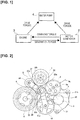
- Figure 1 is a schematic system block diagram of the auxiliary machine-driving device for a vehicle of the first embodiment.
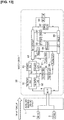
- Figure 2 is a schematic view illustrating the auxiliary machine-driving device for a vehicle of the first embodiment.
- the auxiliary machine-driving device 1 for a vehicle transmits cranking torque from a motor/generator 2 to an engine 3 at the time of an engine start.
- the engine 3 is started by the cranking torque.
- the auxiliary machine-driving device 1 for a vehicle transmits a power generation torque from the engine 3 to the motor/generator 2 after an engine start.
- the motor/generator 2 generates power with the power generation torque and provides electric power to batteries and electrical equipment.
- the auxiliary machine-driving device 1 for a vehicle transmits a drive torque from the engine 3 to the water pump 4 after an engine start.
- the water pump 4 is driven by the drive torque, and cooling water is provided from the water pump 4 to the engine 3.
- the engine 3 is cooled with the supplied cooling water.
- air is warmed using the cooling water that is warmed by the heat from the engine 3 to enable the use of the heater of the air conditioner.
- the auxiliary machine-driving device 1 for a vehicle transmits drive torque from the motor/generator 2 to the water pump 4 when the engine is stopped.
- the water pump 4 is driven by the drive torque, and cooling water is provided from the water pump 4 to the engine 3. Air is warmed using the cooling water that is warmed by the heat from the engine 3 to enable the use of the heater of the air conditioner, even when the engine is stopped.
- the auxiliary machine-driving device 1 for a vehicle carries out the transmission of torque using a friction drive that makes use of a wedging effect.
- the auxiliary machine-driving device 1 for a vehicle comprises a motor/generator roller 5 that integrally rotates with a drive shaft of the motor/generator 2, an engine roller 6 that integrally rotates with a crankshaft of the engine 3, and a water pump roller 7 that integrally rotates with a drive shaft of the water pump 4.
- the motor/generator roller 5, the engine roller 6, and the water pump roller 7 are arranged so that the order will be the engine roller 6, the water pump roller 7 and the motor/generator roller 5 in the direction of rotation (clockwise direction in Figure 2 ) of the engine roller 6.
- a first idler roller 8 that comes into contact with the outer peripheral surfaces of the two is provided.
- the first idler roller 8 is supported by a linking mechanism 30, which is described below, so as to be able to turn freely.
- a second idler roller 9 that comes into contact with the outer peripheral surfaces of the two is provided.
- the second idler roller 9 is supported at a rotational center part via a bearing 9a so as to be able to turn freely.
- the second idler roller 9 is biased in the direction in which the idler roller comes into contact with the outer peripheral surfaces of the water pump roller 7 and the motor/generator roller 5 by a biasing member 9b.
- a third idler roller 10 that comes into contact with the outer peripheral surfaces of the two is provided.
- the third idler roller 10 is supported by a linking mechanism 30 that is described below so as to be able to turn freely.
- the biasing force of the second idler roller 9, due to the biasing member 9b, against the motor/generator roller 5 and the water pump roller 7 is sufficient if the second idler roller 9 is not separated from the motor/generator roller 5 and the water pump roller 7.
- the first idler roller 8, the second idler roller 9, and the third idler roller 10 are provided so that the rotational centers of the first idler roller 8, the second idler roller 9, and the third idler roller 10 are positioned outside of a triangle A that is formed by connecting the rotational centers of the motor/generator roller 5, the engine roller 6, and the water pump roller 7.
- the outer peripheral surfaces of the motor/generator roller 5, the engine roller 6 and the water pump roller 7 are formed from an iron-based metal.
- the outer peripheral surfaces of the first idler roller 8, the second idler roller 9 and the third idler roller 10 are formed from a resin.
- the hardness of the resin that is used to form the outer peripheral surfaces of the first idler roller 8, the second idler roller 9 and the third idler roller 10 is less than the hardness of the iron-based metal that forms the outer peripheral surfaces of the motor/generator roller 5, the engine roller 6 and the water pump roller 7.
- the strength of the resin that is used to form the outer peripheral surfaces of the first idler roller 8, the second idler roller 9 and the third idler roller 10 is less than the strength of the iron-based metal that forms the outer peripheral surfaces of the motor/generator roller 5, the engine roller 6 and the water pump roller 7.
- the material that is used as the resin to form the outer peripheral surfaces of the first idler roller 8, the second idler roller 9 and the third idler roller 10 is such that the coefficients of dynamic friction between the outer peripheral surfaces of the motor/generator roller 5, the engine roller 6 and the water pump roller 7 and the outer peripheral surfaces of the first idler roller 8, the second idler roller 9 and the third idler roller 10 are 0.3 or greater.
- the transmission of torque between two rollers is carried out by a force acting in the direction in which an idler roller bites in between the two rollers in contact with the idler roller, thereby generating a wedging effect.
- the motion of each roller when the wedging effect is generated will be described below.
- Figure 3 is a schematic view of the auxiliary machine-driving device 1 for a vehicle of the first embodiment.
- Figure 3 illustrates the manner in which the torque from a first roller 20 is transmitted to a second roller 22 via an idler roller 21.
- a line B tangent to the first roller 20 and the idler roller 21 and a line C tangent to the idler roller 21 and the second roller 22 intersect at point D.
- the size of the angle formed by the tangent line B and the tangent line C is 2a.
- the torque of the first roller 20 is transmitted to the idler roller 21.
- the idler roller 21 in contact with the first roller 20 rotates to the right.
- the idler roller 21 is pushed in the direction of rotation of the first roller 20 at the point of contact with the first roller 20.
- a force in the same direction as the direction of rotation of the first roller 20 acts on the idler roller 21 at the point of contact with the first roller 20 (force F1).
- the torque of the idler roller 21 is transmitted to the second roller 22.
- the second roller 22 in contact with the idler roller 21 rotates to the left.
- the second roller 22 is pushed in the direction of rotation of the idler roller 21 at the point of contact with the idler roller 21.
- a reaction force in the direction opposite to the direction in which the second roller 22 is pushed acts on the idler roller 21 at the point of contact with the second roller 22 (force F2).
- a force in the direction towards point D acts on the idler roller 21 because of the force F1 and the force F2. For this reason, the contact load of the idler roller 21 against the first roller 20 and the second roller 22 is increased, and the torque can be transmitted from the first roller 20 to the second roller 22 via the idler roller 21.
- the friction force F between the first roller 20 and the idler roller 21, or the friction force F between the idler roller 21 and the second roller 22, can be obtained by the following formula.
- F ⁇ ⁇ A
- T is the shear stress between the first roller 20 and the idler roller 21, or the shear stress between the idler roller 21 and the second roller 22.
- A is the contact area of the first roller 20 and the idler roller 21, or the contact area of the idler roller 21 and the second roller 22.
- the shear stress T is determined by the materials of the contact surface of the first roller 20 and the idler roller 21 and the materials of the contact surface of the idler roller 21 and the second roller 22.
- the contact area A has a high correlation with the contact load of the idler roller 21 against the first roller 20 and the second roller 22 when the aforementioned resin is used for the outer peripheral surface of the idler roller 21, and the greater the contact load, the greater the contact area A.
- Figure 4 is a schematic view of the auxiliary machine-driving device 1 for a vehicle of the first embodiment. Figure 4 illustrates the manner in which the torque from the second roller 22 to the first roller 20 is blocked.
- the torque of the second roller 22 is transmitted to the idler roller 21.
- the idler roller 21 in contact with the second roller 22 rotates to the right.
- the idler roller 21 is pushed in the direction of rotation of the second roller 22 at the point of contact with the second roller 22.
- a force in the same direction as the direction of rotation of the second roller 22 acts on the idler roller 21 at the point of contact with the second roller 22 (force F3).
- the torque of the idler roller 21 is transmitted to the first roller 20.
- the first roller 20 in contact with the idler roller 21 rotates to the left.
- the first roller 20 is pushed in the direction of rotation of the idler roller 21 at the point of contact with the idler roller 21.
- a reaction force in the direction opposite to the direction in which the first roller 20 is pushed acts on the idler roller 21 at the point of contact with the first roller 20 (force F4).
- ⁇ is the coefficient of dynamic friction between the first roller 20 and the idler roller 21, and the coefficient of dynamic friction between the idler roller 21 and the second roller 22.
- the first idler roller 8 and the third idler roller 10 are supported by the linking mechanism 30 to be freely rotatable.
- the first idler roller 8 and the third idler roller 10 switch the contact/separation state of the first idler roller 8 with the engine roller 6 and the water pump roller 7, as well as switch the contact/separation state of the third idler roller 10 with the motor/generator roller 5 and the engine roller 6, in accordance with the motion of the linking mechanism 30.
- Figure 5 is a perspective view illustrating the engine roller 6, the water pump roller 7, the first idler roller 8, the third idler roller 10, and the linking mechanism 30, as well as a perspective view of the members of the linking mechanism 30.
- Figure 6 is a view illustrating the state in which a motor 40 that drives the linking mechanism 30 is attached to the linking mechanism 30.
- Figure 7 is a view of the linking mechanism 30 from several directions.
- Figure 8 is a view of the linking mechanism 30 disassembled into its various components.
- the linking mechanism 30 comprises a first fork 31, a second fork 32, a first eccentric shaft 33, a second eccentric shaft 34, a pivot shaft 35, and a coupling pin 36.
- first fork 31 One end of the first fork 31 is forked into two parts, between which a roller retaining part 31a, which retains the third idler roller 10, is formed.
- the other end of the first fork 31 is also forked into two parts, between which an inserted part 31b, into which the second fork 32 is inserted, is formed.
- a through-hole penetrating both of the forked members is formed in the inserted part 31b, and the through-hole constitutes an eccentric shaft retaining part 31c that retains the first eccentric shaft 33.
- One end of the second fork 32 is forked into two parts, between which a roller retaining part 32a, which retains the first idler roller 8, is formed.
- the other end of the second fork 32 is a single plate, at the tip of which an insertion part 32b, which is inserted into the inserted part 31b of the first fork 31 that is forked into two parts, is formed.
- a through-hole that penetrates the insertion part 32b is formed, and the through-hole constitutes an eccentric shaft retaining part 32c that retains the second eccentric shaft 34.
- the first eccentric shaft 33 is formed with a shape that integrally connects three disk-shaped members.
- the three disk-shaped members are a large diameter part 33a, a first small diameter part 33b, and a second small diameter part 33c.
- the three members are integrally formed in a state in which the first small diameter part 33b and the second small diameter part 33c are eccentric with respect to the center axis of the large diameter part 33a.
- the center axis of the first small diameter part 33b and the center axis of the second small diameter part 33c are concentrically disposed.
- the first small diameter part 33b and the second small diameter part 33c are inserted into the eccentric shaft retaining part 31c of the first fork 31 and are fixed with respect to the first fork 31.
- a through-hole 33a1 having an inner diameter concentric with the center axis of the large diameter part 33a is formed in the large diameter part 33a.
- Two through-holes are formed in the first small diameter part 33b and the second small diameter part 33c.
- One forms shaft insertion holes 33b1 and 33c1, into which the pivot shaft 35 is inserted, and the other forms pin insertion holes 33b2 and 33c2, into which the coupling pin 36 is inserted.
- Shaft insertion holes 33b1 and 33c1 are disposed in eccentric positions with respect to the center axis of the first small diameter part 33b and the second small diameter part 33c.
- the second eccentric shaft 34 is a disk-shaped member. Two through-holes are formed in the second eccentric shaft 34. One is a shaft insertion hole 34a, into which the pivot shaft 35 is inserted, and the other is a pin insertion hole 34b, into which the coupling pin 36 is inserted.
- the shaft insertion hole 34a is disposed in an eccentric position with respect to the center axis of the second eccentric shaft 34.
- the second eccentric shaft 34 is inserted into the eccentric shaft retaining part 32c of the second fork 32 and is fixed with respect to the second fork 32.
- the first eccentric shaft 33 and the second eccentric shaft 34 are coupled by the pivot shaft 35 and the coupling pin 36.
- the first eccentric shaft 33 and the second eccentric shaft 34 integrally rotate about the axis of rotation of the pivot shaft 35.
- Figure 9 is a view illustrating the motions of the linking mechanism 30.
- Figure 9(a) is a view illustrating a state in which the first idler roller 8 is in contact with the engine roller 6 and the water pump roller 7, and the third idler roller 10 is in contact with the motor/generator roller 5 and the engine roller 6.
- Figure 9(b) is a view illustrating a state in which the first idler roller 8 is separated from the engine roller 6 and the water pump roller 7, and the third idler roller 10 is separated from the motor/generator roller 5 and the engine roller 6.
- the axis of rotation of the pivot shaft 35 is Op
- the center axis of the first small diameter part 33b and the second small diameter part 33c of the first eccentric shaft 33 is O1
- the center axis of the second eccentric shaft 34 is O2.
- the center axis of the first small diameter part 33b and the second small diameter part 33c of the first eccentric shaft 33 is moved from position O1 to O1'
- the center axis of the second eccentric shaft 34 is moved from position O2 to O2'.
- the first small diameter part 33b and the second small diameter part 33c of the first eccentric shaft 33 are fixed with respect to the first fork 31. For this reason, the first fork 31 also moves insofar as the center axis moves from O1 to O1'. Thus, the first fork 31 moves the first idler roller 8 away from the engine roller 6 and the water pump roller 7.
- the second eccentric shaft 34 is fixed with respect to the second fork 32. For this reason, the second fork 32 also moves insofar as the center axis moves from O2 to O2'. Thus, the second fork 32 moves the third idler roller 10 away from the motor/generator roller 5 and the engine roller 6.
- Figure 10 is a view illustrating the motions of the members of the auxiliary machine-driving device 1 for a vehicle at the time of an engine start.
- the cranking of the engine 3 is carried out by the drive torque of the motor/generator 2.
- the first idler roller 8 is made to come into contact with the engine roller 6 and the water pump roller 7, and the third idler roller 10 is made to come into contact with the motor/generator roller 5 and the engine roller 6, by the linking mechanism 30.
- the motor/generator roller 2 is driven, and the motor/generator roller 5 is rotated to the right in Figure 10 .
- the third idler roller 10 is rotated to the left by the motor/generator roller 5, and the engine roller 6 is rotated to the right by the third idler roller 10.
- a force acts on the third idler roller 10 in the direction in which the idler roller bites in between the motor/generator roller 5 and the engine roller 6.
- the drive torque of the motor/generator 2 is transmitted to the engine 3 via the third idler roller 10.
- the engine roller 6 is rotated to the right due to the drive torque from the motor/generator roller 5.
- the first idler roller 8 is rotated to the left by the engine roller 6, and the water pump roller 7 is rotated to the right by the first idler roller 8.
- a force acts on the first idler roller 8 in the direction in which the idler roller bites in between the engine roller 6 and the water pump roller 7.
- part of the drive torque that is transmitted from the motor/generator roller 5 to the engine roller 6 is transmitted to the water pump roller 7 via the first idler roller 8.
- the second idler roller 9 is rotated to the left by the motor/generator roller 5, and the water pump roller 7 is rotated to the right by the second idler roller 9. At this time, a force acts on the second idler roller 9 in the direction away from the line of contact between the motor/generator roller 5 and the water pump roller 7. As a result, the torque from the motor/generator roller 5 to the water pump roller 7 via the second idler roller 9 is hardly transmitted.
- Figure 11 is a view illustrating the motions of the members of the auxiliary machine-driving device 1 for a vehicle after an engine start. After the engine starts, the motor/generator 2 generates power with the torque of the engine 3.
- the first idler roller 8 is made to come into contact with the engine roller 6 and the water pump roller 7, and the third idler roller 10 is made to come into contact with the motor/generator roller 5 and the engine roller 6, by the linking mechanism 30.
- the engine roller 6 is rotated to the right by the drive torque of the engine 3.
- the first idler roller 8 is rotated to the left by the engine roller 6, and the water pump roller 7 is rotated to the right by the first idler roller 8.
- a force acts on the first idler roller 8 in the direction in which the idler roller bites in between the engine roller 6 and the water pump roller 7.
- the drive torque of the engine roller 6 is transmitted to the water pump roller 7 via the first idler roller 8.
- the water pump roller 7 is rotated to the right by the torque from the engine roller 6.
- the second idler roller 9 is rotated to the left by the water pump roller 7, and the motor/generator roller 5 is rotated to the right by the second idler roller 9.
- a force acts on the second idler roller 9 in the direction in which the idler roller bites in between the water pump roller 7 and the motor/generator roller 5.
- part of the torque transmitted from the engine roller 6 to the water pump roller 7 is transmitted to the motor/generator roller 5 via the second idler roller 9.
- the third idler roller 10 is rotated to the left by the engine roller 6, and the motor/generator roller 5 is rotated to the right by the second idler roller 9. At this time, a force acts on the third idler roller 10 in the direction away from the line of contact between the engine roller 6 and the motor/generator roller 5. As a result, the torque from the engine roller 6 to the motor/generator roller 5 via the third idler roller 10 is hardly transmitted.
- Figure 12 is a view illustrating the motions of the members of the auxiliary machine-driving device 1 for a vehicle when the engine is stopped.
- the water pump 4 is driven by the motor/generator 2.
- the first idler roller 8 is separated from the engine roller 6 and the water pump roller 7, and the third idler roller 10 is separated from the motor/generator roller 5 and the engine roller 6, by the linking mechanism 30.
- the motor/generator roller 2 is driven, and the motor/generator roller 5 is rotated to the right in Figure 12 .
- the second idler roller 9 is rotated to the left by the motor/generator roller 5, and the water pump roller 7 is rotated to the right by the second idler roller 9.
- a force acts on the second idler roller 9 in the direction away from the line of contact between the motor/generator roller 5 and the water pump roller 7, and the wedging effect cannot be effected.
- the load of the water pump 4 is not large, the water pump 4 can be sufficiently driven even if the wedging effect does not occur, and cooling water is supplied to the engine 3 from the water pump 4.
- Figure 13 is a view illustrating the water circuit 50 of the cooling water.
- the water pump 4 is driven by the engine 3 after the engine starts, and is driven by the motor/generator 2 when the engine is stopped.
- the cooling water discharged from the water pump 4 is first supplied to a right cylinder block 51 and a left cylinder block 52.
- the cooling water that has passed through the right cylinder block 51 is sent to a right cylinder head 53 and a right throttle chamber 55.
- the cooling water that has passed through the left cylinder block 52 is sent to a left cylinder head 54 and the right throttle chamber 55.
- the cooling water that has passed through the right throttle chamber 55 is sent to a left throttle chamber 56.
- the cooling water that has passed through the left throttle chamber 56 is sent to a left turbocharger 58.
- the cooling water that has passed through the left turbocharger 58 is sent to a water inlet 65.
- the cooling water that has passed through the right cylinder head 53 and the left cylinder head 53 is sent to a water outlet 64.
- the cooling water that has passed through the water inlet 65 is sent to a right turbocharger 57, a heater 59, a reservoir 60, a radiator 61, an engine oil cooler 62, and an automatic transmission fluid cooler 63.
- the cooling water that has passed through the right turbocharger 57 is sent to the water inlet 65.
- the cooling water that has passed through the heater 59 is sent to the water inlet 65.
- the air that is used for the heater of the air conditioner is warmed by the cooling water.
- the cooling water that has passed through the reservoir 60 is sent to the water inlet 65.
- the cooling water that has passed through the radiator 61 is sent to the water inlet 65.
- the cooling water that has passed through the engine oil cooler 62 is sent to the water inlet 65.
- the cooling water that has passed through the automatic transmission fluid cooler 63 is sent to the water inlet 65.
- Part of the cooling water that has passed through the water inlet 65 is directly sent to the water inlet 65 from a bypass flow channel 66.
- the cooling water that has passed through the water inlet 65 is again sent to the water pump 4.
- an electric water pump was provided, apart from the water pump driven by the engine, in order to drive the water pump when the engine is stopped.
- providing two water pumps created such problems as increased cost and increased size of the engine cooling system.
- the water pump 4 that is driven by the engine 3 is driven by another drive source when the engine is stopped.
- the water pump 4 is driven by another drive source, it is necessary to cut off the transmission of power between the engine 3 and the water pump 4, which is a high load.
- the first idler roller 8 is disposed between the engine roller 6 and the water pump roller 7
- the second idler roller 9 is disposed between the motor/generator roller 5 and the water pump roller 7
- the third idler roller 10 is disposed between the motor/generator roller 5 and the engine roller 6.
- the linking mechanism 30, which supports the rotational shaft of the first idler roller 8 and the rotational shaft of the third idler roller 10, is proved. And, the linking mechanism 30 is driven by a single motor 40 (actuator), and the positions of the first idler roller 8 and the third idler roller 10 are changed. Specifically, the first idler roller 8 is switched between a state in which the idler roller is in contact with, and a state in which the idler roller is separated from, the engine roller 6 and the water pump roller 7, and the third idler roller 10 is switched between a state in which the idler roller is in contact with both, and a state in which the idler roller is separated from at least one of the motor/generator roller 5 and the engine roller 6, by the linking mechanism 30.
- the positions of the first idler roller 8 and the third idler roller 10 can be changed simultaneously with a single motor 40. For this reason, the cost of the auxiliary machine-driving device 1 for a vehicle can be reduced, and the increase in size of the auxiliary machine-driving device 1 for a vehicle can be suppressed.
- the motor/generator 2 is used as another drive source for driving the water pump 4, which was driven by the engine 3, when the engine is stopped.
- the motor/generator 2 comprises the functions of a starter motor for starting the engine 3 and an alternator for generating power, and also comprises the function of driving the water pump 4.
- the motor/generator 2 In order for the motor/generator 2 to fulfill the three functions described above, it is necessary that the motor/generator 2 and the engine 3 be connected to be capable of transmitting power at the time of an engine start and after the engine starts, and that the motor/generator 2 and the engine 3 be disconnected to be incapable of transmitting power when the engine is stopped. This is because if the motor/generator 2 and the engine 3 are connected in order to be capable of transmitting power when the engine is stopped and the water pump 4 is driven by the motor/generator 2, the load on the motor/generator 2 is increased.
- the first idler roller 8 is switched between a state in which the idler roller is in contact with, and a state in which the idler roller is separated from, the engine roller 6 and the water pump roller 7, and the third idler roller 10 is switched between a state in which the idler roller is in contact with both, and a state in which the idler roller is separated from at least one of the motor/generator roller 5 and the engine roller 6, by the linking mechanism 30, as described above.
- the water pump 4 can be driven by the motor/generator 2. For this reason, there is no need to provide a separate electric water pump, etc., in addition to the water pump 4 that is driven by the engine 3. Also, the water pump 4 can also be driven using the motor/generator 2 that starts the engine 3 and that generates power. Thus, the heater can be used when the engine is stopped without the addition of another water pump or a drive source for driving the water pump.
- the heater can be used when the engine is stopped without the addition of another water pump or a drive source.
- auxiliary machines that drive synchronously with the engine 3 may be used instead of the water pump 4 of the first embodiment.
- the water pump 4 may be driven by another drive source, unlike the first embodiment in which the water pump is driven by the motor/generator 2, when the engine is stopped.
Landscapes
- Engineering & Computer Science (AREA)
- General Engineering & Computer Science (AREA)
- Mechanical Engineering (AREA)
- Chemical & Material Sciences (AREA)
- Combustion & Propulsion (AREA)
- Friction Gearing (AREA)
Abstract
Description
- The present invention relates to an auxiliary machine-driving device for a vehicle.
- As the type of technique therefor, the technique described in Patent Document 1 below has been disclosed. The document discloses a technique in which, by moving the position of a single friction wheel with a single actuator, a state in which the friction wheel comes into contact with both a belt and a driven pulley and a state in which the friction wheel comes into contact with just the belt are switched. Driving with the actuator enables switching between connecting/disconnecting the transmission of torque via the belt onto the driven pulley.
- Patent Document 1: Japanese Laid-Open Patent Application No.
2008-531946 - When enabling the switching between connecting/disconnecting the transmission of torque between a pair of rollers by using the technique described in the above-referenced patent document 1, two or more actuators are required. For this reason, there was the problem of increased cost.
- In view of the problem described above, an object of the present invention is to provide an auxiliary machine-driving device for a vehicle that reduces the cost by reducing the number of actuators that enable switching between connecting/disconnecting the transmission of torque when enabling the switching between connecting/disconnecting the transmission of torque between a pair of rollers.
- The auxiliary machine-driving device for a vehicle is provided with a first idler roller disposed between an engine roller and a first rotating roller, a second idler roller disposed between the first rotating roller and a second rotating roller, a third idler roller disposed between the second rotating roller and the engine roller, and a linking mechanism that is driven by one actuator and that changes the position of the first idler roller so as to switch between a state in which the first idler roller makes contact with outer peripheral surfaces of the engine roller and the first rotating roller, and a state in which the first idler roller is separated from the engine roller and the first rotating roller, and that also changes the position of the second idler roller and/or the third idler roller so as to switch between a state in which at least one of the second idler roller and the third idler roller makes contact, at the outer peripheral surfaces, with two rollers that are adjacent to said at least one roller, and a state in which said at least one roller is separated from the two adjacent rollers.
- Therefore, with the present invention, the number of actuators can be suppressed and the cost can be reduced.
-
- [
Figure 1 ] is a schematic system block diagram of the auxiliary machine-driving device for a vehicle in a first embodiment. - [
Figure 2 ] is a schematic view illustrating the auxiliary machine-driving device for a vehicle of the first embodiment. - [
Figure 3 ] is a schematic view of the auxiliary machine-driving device for a vehicle of the first embodiment. - [
Figure 4 ] is a schematic view of the auxiliary machine-driving device for a vehicle of the first embodiment. - [
Figure 5 ] is a perspective view illustrating the linking mechanism of the first embodiment. - [
Figure 6 ] is a view illustrating the linking mechanism of the first embodiment. - [
Figure 7 ] is a view illustrating the linking mechanism of the first embodiment. - [
Figure 8 ] is a view illustrating the linking mechanism of the first embodiment. - [
Figure 9 ] is a view illustrating the motions of the linking mechanism of the first embodiment. - [
Figure 10 ] is a view illustrating the motions of the members of the auxiliary machine-driving device for a vehicle of the first embodiment at the time of an engine start. - [
Figure 11 ] is a view illustrating the motions of the members of the auxiliary machine-driving device for a vehicle of the first embodiment after an engine start. - [
Figure 12 ] is a view illustrating the motions of the members of the auxiliary machine-driving device for a vehicle of the first embodiment when the engine is stopped. - [
Figure 13 ] is a view illustrating the water circuit of the cooling water. -
- 1
- Auxiliary machine-driving device for a vehicle
- 2
- Motor/generator (second auxiliary machine)
- 3
- Engine
- 4
- Water pump (first auxiliary machine)
- 5
- Motor/generator roller (second rotating roller)
- 6
- Engine roller
- 7
- Water pump roller (first rotating roller)
- 8
- First idler roller
- 9
- Second idler roller
- 10
- Third idler roller
- 30
- Linking mechanism
- 40
- Motor (actuator)
- The auxiliary machine-driving device 1 for a vehicle of the first embodiment will now be described.
Figure 1 is a schematic system block diagram of the auxiliary machine-driving device for a vehicle of the first embodiment.Figure 2 is a schematic view illustrating the auxiliary machine-driving device for a vehicle of the first embodiment. - The auxiliary machine-driving device 1 for a vehicle transmits cranking torque from a motor/
generator 2 to anengine 3 at the time of an engine start. Theengine 3 is started by the cranking torque. - The auxiliary machine-driving device 1 for a vehicle transmits a power generation torque from the
engine 3 to the motor/generator 2 after an engine start. The motor/generator 2 generates power with the power generation torque and provides electric power to batteries and electrical equipment. The auxiliary machine-driving device 1 for a vehicle transmits a drive torque from theengine 3 to thewater pump 4 after an engine start. Thewater pump 4 is driven by the drive torque, and cooling water is provided from thewater pump 4 to theengine 3. Theengine 3 is cooled with the supplied cooling water. In addition, air is warmed using the cooling water that is warmed by the heat from theengine 3 to enable the use of the heater of the air conditioner. - The auxiliary machine-driving device 1 for a vehicle transmits drive torque from the motor/
generator 2 to thewater pump 4 when the engine is stopped. Thewater pump 4 is driven by the drive torque, and cooling water is provided from thewater pump 4 to theengine 3. Air is warmed using the cooling water that is warmed by the heat from theengine 3 to enable the use of the heater of the air conditioner, even when the engine is stopped. - The auxiliary machine-driving device 1 for a vehicle carries out the transmission of torque using a friction drive that makes use of a wedging effect. The auxiliary machine-driving device 1 for a vehicle comprises a motor/
generator roller 5 that integrally rotates with a drive shaft of the motor/generator 2, anengine roller 6 that integrally rotates with a crankshaft of theengine 3, and awater pump roller 7 that integrally rotates with a drive shaft of thewater pump 4. - The motor/
generator roller 5, theengine roller 6, and thewater pump roller 7 are arranged so that the order will be theengine roller 6, thewater pump roller 7 and the motor/generator roller 5 in the direction of rotation (clockwise direction inFigure 2 ) of theengine roller 6. - Between the
engine roller 6 and thewater pump roller 7, a firstidler roller 8 that comes into contact with the outer peripheral surfaces of the two is provided. Thefirst idler roller 8 is supported by a linkingmechanism 30, which is described below, so as to be able to turn freely. - Between the
water pump roller 7 and the motor/generator roller 5, asecond idler roller 9 that comes into contact with the outer peripheral surfaces of the two is provided. Thesecond idler roller 9 is supported at a rotational center part via abearing 9a so as to be able to turn freely. Thesecond idler roller 9 is biased in the direction in which the idler roller comes into contact with the outer peripheral surfaces of thewater pump roller 7 and the motor/generator roller 5 by a biasingmember 9b. - Between the motor/
generator roller 5 and theengine roller 6, athird idler roller 10 that comes into contact with the outer peripheral surfaces of the two is provided. Thethird idler roller 10 is supported by a linkingmechanism 30 that is described below so as to be able to turn freely. - The biasing force of the
second idler roller 9, due to the biasingmember 9b, against the motor/generator roller 5 and thewater pump roller 7 is sufficient if thesecond idler roller 9 is not separated from the motor/generator roller 5 and thewater pump roller 7. - The
first idler roller 8, thesecond idler roller 9, and thethird idler roller 10 are provided so that the rotational centers of thefirst idler roller 8, thesecond idler roller 9, and thethird idler roller 10 are positioned outside of a triangle A that is formed by connecting the rotational centers of the motor/generator roller 5, theengine roller 6, and thewater pump roller 7. - The outer peripheral surfaces of the motor/
generator roller 5, theengine roller 6 and thewater pump roller 7 are formed from an iron-based metal. The outer peripheral surfaces of thefirst idler roller 8, thesecond idler roller 9 and thethird idler roller 10 are formed from a resin. - The hardness of the resin that is used to form the outer peripheral surfaces of the
first idler roller 8, thesecond idler roller 9 and thethird idler roller 10 is less than the hardness of the iron-based metal that forms the outer peripheral surfaces of the motor/generator roller 5, theengine roller 6 and thewater pump roller 7. - The strength of the resin that is used to form the outer peripheral surfaces of the
first idler roller 8, thesecond idler roller 9 and thethird idler roller 10 is less than the strength of the iron-based metal that forms the outer peripheral surfaces of the motor/generator roller 5, theengine roller 6 and thewater pump roller 7. - The material that is used as the resin to form the outer peripheral surfaces of the
first idler roller 8, thesecond idler roller 9 and thethird idler roller 10 is such that the coefficients of dynamic friction between the outer peripheral surfaces of the motor/generator roller 5, theengine roller 6 and thewater pump roller 7 and the outer peripheral surfaces of thefirst idler roller 8, thesecond idler roller 9 and thethird idler roller 10 are 0.3 or greater. - In the auxiliary machine-driving device 1 for a vehicle of the first embodiment, the transmission of torque between two rollers is carried out by a force acting in the direction in which an idler roller bites in between the two rollers in contact with the idler roller, thereby generating a wedging effect. The motion of each roller when the wedging effect is generated will be described below.
-
Figure 3 is a schematic view of the auxiliary machine-driving device 1 for a vehicle of the first embodiment.Figure 3 illustrates the manner in which the torque from afirst roller 20 is transmitted to asecond roller 22 via anidler roller 21. A line B tangent to thefirst roller 20 and theidler roller 21 and a line C tangent to theidler roller 21 and thesecond roller 22 intersect at point D. The size of the angle formed by the tangent line B and the tangent line C is 2a. - The torque of the
first roller 20 is transmitted to theidler roller 21. InFigure 3 , when thefirst roller 20 rotates to the left, theidler roller 21 in contact with thefirst roller 20 rotates to the right. At this time, theidler roller 21 is pushed in the direction of rotation of thefirst roller 20 at the point of contact with thefirst roller 20. A force in the same direction as the direction of rotation of thefirst roller 20 acts on theidler roller 21 at the point of contact with the first roller 20 (force F1). - The torque of the
idler roller 21 is transmitted to thesecond roller 22. InFigure 3 , when theidler roller 21 rotates to the right, thesecond roller 22 in contact with theidler roller 21 rotates to the left. At this time, thesecond roller 22 is pushed in the direction of rotation of theidler roller 21 at the point of contact with theidler roller 21. A reaction force in the direction opposite to the direction in which thesecond roller 22 is pushed acts on theidler roller 21 at the point of contact with the second roller 22 (force F2). - A force in the direction towards point D acts on the
idler roller 21 because of the force F1 and the force F2. For this reason, the contact load of theidler roller 21 against thefirst roller 20 and thesecond roller 22 is increased, and the torque can be transmitted from thefirst roller 20 to thesecond roller 22 via theidler roller 21. - The larger the load of the
second roller 22 becomes (the larger the torque transmitted from thefirst roller 20 to thesecond roller 22 becomes), the larger the force in the direction towards point D that acts on theidler roller 21 becomes. The friction force F between thefirst roller 20 and theidler roller 21, or the friction force F between theidler roller 21 and thesecond roller 22, can be obtained by the following formula.
first roller 20 and theidler roller 21, or the shear stress between theidler roller 21 and thesecond roller 22. A is the contact area of thefirst roller 20 and theidler roller 21, or the contact area of theidler roller 21 and thesecond roller 22. - The shear stress T is determined by the materials of the contact surface of the
first roller 20 and theidler roller 21 and the materials of the contact surface of theidler roller 21 and thesecond roller 22. The contact area A has a high correlation with the contact load of theidler roller 21 against thefirst roller 20 and thesecond roller 22 when the aforementioned resin is used for the outer peripheral surface of theidler roller 21, and the greater the contact load, the greater the contact area A. -
Figure 4 is a schematic view of the auxiliary machine-driving device 1 for a vehicle of the first embodiment.Figure 4 illustrates the manner in which the torque from thesecond roller 22 to thefirst roller 20 is blocked. - The torque of the
second roller 22 is transmitted to theidler roller 21. InFigure 4 , when thesecond roller 22 rotates to the left, theidler roller 21 in contact with thesecond roller 22 rotates to the right. At this time, theidler roller 21 is pushed in the direction of rotation of thesecond roller 22 at the point of contact with thesecond roller 22. A force in the same direction as the direction of rotation of thesecond roller 22 acts on theidler roller 21 at the point of contact with the second roller 22 (force F3). - The torque of the
idler roller 21 is transmitted to thefirst roller 20. InFigure 4 , when theidler roller 21 rotates to the right, thefirst roller 20 in contact with theidler roller 21 rotates to the left. At this time, thefirst roller 20 is pushed in the direction of rotation of theidler roller 21 at the point of contact with theidler roller 21. A reaction force in the direction opposite to the direction in which thefirst roller 20 is pushed acts on theidler roller 21 at the point of contact with the first roller 20 (force F4). - A force in the direction away from point D acts on the
idler roller 21 due to the force F3 and the force F4. For this reason, the contact load of theidler roller 21 against thefirst roller 20 and thesecond roller 22 decreases. Thus, the transmission of the torque from thesecond roller 22 to theidler roller 21 and the transmission of the torque from theidler roller 21 to thefirst roller 20 are hardly carried out. - In order to generate a wedging effect as described above, the positional relationship of the
first roller 20, theidler roller 21 and thesecond roller 22 must satisfy the following formula.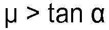
first roller 20 and theidler roller 21, and the coefficient of dynamic friction between theidler roller 21 and thesecond roller 22. - The
first idler roller 8 and thethird idler roller 10 are supported by the linkingmechanism 30 to be freely rotatable. Thefirst idler roller 8 and thethird idler roller 10 switch the contact/separation state of thefirst idler roller 8 with theengine roller 6 and thewater pump roller 7, as well as switch the contact/separation state of thethird idler roller 10 with the motor/generator roller 5 and theengine roller 6, in accordance with the motion of the linkingmechanism 30. -
Figure 5 is a perspective view illustrating theengine roller 6, thewater pump roller 7, thefirst idler roller 8, thethird idler roller 10, and thelinking mechanism 30, as well as a perspective view of the members of the linkingmechanism 30.Figure 6 is a view illustrating the state in which amotor 40 that drives the linkingmechanism 30 is attached to thelinking mechanism 30.Figure 7 is a view of the linkingmechanism 30 from several directions.Figure 8 is a view of the linkingmechanism 30 disassembled into its various components. - The linking
mechanism 30 comprises afirst fork 31, asecond fork 32, a firsteccentric shaft 33, a secondeccentric shaft 34, apivot shaft 35, and acoupling pin 36. - One end of the
first fork 31 is forked into two parts, between which aroller retaining part 31a, which retains thethird idler roller 10, is formed. The other end of thefirst fork 31 is also forked into two parts, between which an insertedpart 31b, into which thesecond fork 32 is inserted, is formed. A through-hole penetrating both of the forked members is formed in the insertedpart 31b, and the through-hole constitutes an eccentricshaft retaining part 31c that retains the firsteccentric shaft 33. - One end of the
second fork 32 is forked into two parts, between which aroller retaining part 32a, which retains thefirst idler roller 8, is formed. The other end of thesecond fork 32 is a single plate, at the tip of which aninsertion part 32b, which is inserted into the insertedpart 31b of thefirst fork 31 that is forked into two parts, is formed. A through-hole that penetrates theinsertion part 32b is formed, and the through-hole constitutes an eccentricshaft retaining part 32c that retains the secondeccentric shaft 34. - The first
eccentric shaft 33 is formed with a shape that integrally connects three disk-shaped members. The three disk-shaped members are alarge diameter part 33a, a firstsmall diameter part 33b, and a secondsmall diameter part 33c. The three members are integrally formed in a state in which the firstsmall diameter part 33b and the secondsmall diameter part 33c are eccentric with respect to the center axis of thelarge diameter part 33a. The center axis of the firstsmall diameter part 33b and the center axis of the secondsmall diameter part 33c are concentrically disposed. The firstsmall diameter part 33b and the secondsmall diameter part 33c are inserted into the eccentricshaft retaining part 31c of thefirst fork 31 and are fixed with respect to thefirst fork 31. - A through-hole 33a1 having an inner diameter concentric with the center axis of the
large diameter part 33a is formed in thelarge diameter part 33a. Two through-holes are formed in the firstsmall diameter part 33b and the secondsmall diameter part 33c. One forms shaft insertion holes 33b1 and 33c1, into which thepivot shaft 35 is inserted, and the other forms pin insertion holes 33b2 and 33c2, into which thecoupling pin 36 is inserted. Shaft insertion holes 33b1 and 33c1 are disposed in eccentric positions with respect to the center axis of the firstsmall diameter part 33b and the secondsmall diameter part 33c. - The second
eccentric shaft 34 is a disk-shaped member. Two through-holes are formed in the secondeccentric shaft 34. One is a shaft insertion hole 34a, into which thepivot shaft 35 is inserted, and the other is a pin insertion hole 34b, into which thecoupling pin 36 is inserted. The shaft insertion hole 34a is disposed in an eccentric position with respect to the center axis of the secondeccentric shaft 34. The secondeccentric shaft 34 is inserted into the eccentricshaft retaining part 32c of thesecond fork 32 and is fixed with respect to thesecond fork 32. - The first
eccentric shaft 33 and the secondeccentric shaft 34 are coupled by thepivot shaft 35 and thecoupling pin 36. When thepivot shaft 35 rotates, the firsteccentric shaft 33 and the secondeccentric shaft 34 integrally rotate about the axis of rotation of thepivot shaft 35. -
Figure 9 is a view illustrating the motions of the linkingmechanism 30.Figure 9(a) is a view illustrating a state in which thefirst idler roller 8 is in contact with theengine roller 6 and thewater pump roller 7, and thethird idler roller 10 is in contact with the motor/generator roller 5 and theengine roller 6.Figure 9(b) is a view illustrating a state in which thefirst idler roller 8 is separated from theengine roller 6 and thewater pump roller 7, and thethird idler roller 10 is separated from the motor/generator roller 5 and theengine roller 6. - In
Figure 9 , the axis of rotation of thepivot shaft 35 is Op, the center axis of the firstsmall diameter part 33b and the secondsmall diameter part 33c of the firsteccentric shaft 33 is O1, and the center axis of the secondeccentric shaft 34 is O2. InFigure 9 , when thepivot shaft 35 rotates to the right, the center axis of the firstsmall diameter part 33b and the secondsmall diameter part 33c of the firsteccentric shaft 33 is moved from position O1 to O1', and the center axis of the secondeccentric shaft 34 is moved from position O2 to O2'. - The first
small diameter part 33b and the secondsmall diameter part 33c of the firsteccentric shaft 33 are fixed with respect to thefirst fork 31. For this reason, thefirst fork 31 also moves insofar as the center axis moves from O1 to O1'. Thus, thefirst fork 31 moves thefirst idler roller 8 away from theengine roller 6 and thewater pump roller 7. - The second
eccentric shaft 34 is fixed with respect to thesecond fork 32. For this reason, thesecond fork 32 also moves insofar as the center axis moves from O2 to O2'. Thus, thesecond fork 32 moves thethird idler roller 10 away from the motor/generator roller 5 and theengine roller 6. - [Behavior of the auxiliary machine-driving Device]
-
Figure 10 is a view illustrating the motions of the members of the auxiliary machine-driving device 1 for a vehicle at the time of an engine start. When the engine starts, the cranking of theengine 3 is carried out by the drive torque of the motor/generator 2. - At the time of an engine start, the
first idler roller 8 is made to come into contact with theengine roller 6 and thewater pump roller 7, and thethird idler roller 10 is made to come into contact with the motor/generator roller 5 and theengine roller 6, by the linkingmechanism 30. - The motor/
generator roller 2 is driven, and the motor/generator roller 5 is rotated to the right inFigure 10 . Thethird idler roller 10 is rotated to the left by the motor/generator roller 5, and theengine roller 6 is rotated to the right by thethird idler roller 10. At this time, a force acts on thethird idler roller 10 in the direction in which the idler roller bites in between the motor/generator roller 5 and theengine roller 6. As a result, the drive torque of the motor/generator 2 is transmitted to theengine 3 via thethird idler roller 10. - The
engine roller 6 is rotated to the right due to the drive torque from the motor/generator roller 5. Thefirst idler roller 8 is rotated to the left by theengine roller 6, and thewater pump roller 7 is rotated to the right by thefirst idler roller 8. At this time, a force acts on thefirst idler roller 8 in the direction in which the idler roller bites in between theengine roller 6 and thewater pump roller 7. As a result, part of the drive torque that is transmitted from the motor/generator roller 5 to theengine roller 6 is transmitted to thewater pump roller 7 via thefirst idler roller 8. - The
second idler roller 9 is rotated to the left by the motor/generator roller 5, and thewater pump roller 7 is rotated to the right by thesecond idler roller 9. At this time, a force acts on thesecond idler roller 9 in the direction away from the line of contact between the motor/generator roller 5 and thewater pump roller 7. As a result, the torque from the motor/generator roller 5 to thewater pump roller 7 via thesecond idler roller 9 is hardly transmitted. -
Figure 11 is a view illustrating the motions of the members of the auxiliary machine-driving device 1 for a vehicle after an engine start. After the engine starts, the motor/generator 2 generates power with the torque of theengine 3. - After the engine starts, also, the
first idler roller 8 is made to come into contact with theengine roller 6 and thewater pump roller 7, and thethird idler roller 10 is made to come into contact with the motor/generator roller 5 and theengine roller 6, by the linkingmechanism 30. - In
Figure 11 , theengine roller 6 is rotated to the right by the drive torque of theengine 3. Thefirst idler roller 8 is rotated to the left by theengine roller 6, and thewater pump roller 7 is rotated to the right by thefirst idler roller 8. At this time, a force acts on thefirst idler roller 8 in the direction in which the idler roller bites in between theengine roller 6 and thewater pump roller 7. As a result, the drive torque of theengine roller 6 is transmitted to thewater pump roller 7 via thefirst idler roller 8. - The
water pump roller 7 is rotated to the right by the torque from theengine roller 6. Thesecond idler roller 9 is rotated to the left by thewater pump roller 7, and the motor/generator roller 5 is rotated to the right by thesecond idler roller 9. At this time, a force acts on thesecond idler roller 9 in the direction in which the idler roller bites in between thewater pump roller 7 and the motor/generator roller 5. As a result, part of the torque transmitted from theengine roller 6 to thewater pump roller 7 is transmitted to the motor/generator roller 5 via thesecond idler roller 9. - The
third idler roller 10 is rotated to the left by theengine roller 6, and the motor/generator roller 5 is rotated to the right by thesecond idler roller 9. At this time, a force acts on thethird idler roller 10 in the direction away from the line of contact between theengine roller 6 and the motor/generator roller 5. As a result, the torque from theengine roller 6 to the motor/generator roller 5 via thethird idler roller 10 is hardly transmitted. -
Figure 12 is a view illustrating the motions of the members of the auxiliary machine-driving device 1 for a vehicle when the engine is stopped. When the engine is stopped, thewater pump 4 is driven by the motor/generator 2. - When the engine is stopped, the
first idler roller 8 is separated from theengine roller 6 and thewater pump roller 7, and thethird idler roller 10 is separated from the motor/generator roller 5 and theengine roller 6, by the linkingmechanism 30. - The motor/
generator roller 2 is driven, and the motor/generator roller 5 is rotated to the right inFigure 12 . Thesecond idler roller 9 is rotated to the left by the motor/generator roller 5, and thewater pump roller 7 is rotated to the right by thesecond idler roller 9. At this time, a force acts on thesecond idler roller 9 in the direction away from the line of contact between the motor/generator roller 5 and thewater pump roller 7, and the wedging effect cannot be effected. However, since the load of thewater pump 4 is not large, thewater pump 4 can be sufficiently driven even if the wedging effect does not occur, and cooling water is supplied to theengine 3 from thewater pump 4. -
Figure 13 is a view illustrating thewater circuit 50 of the cooling water. Thewater pump 4 is driven by theengine 3 after the engine starts, and is driven by the motor/generator 2 when the engine is stopped. - The cooling water discharged from the
water pump 4 is first supplied to aright cylinder block 51 and aleft cylinder block 52. The cooling water that has passed through theright cylinder block 51 is sent to aright cylinder head 53 and aright throttle chamber 55. The cooling water that has passed through theleft cylinder block 52 is sent to aleft cylinder head 54 and theright throttle chamber 55. - The cooling water that has passed through the
right throttle chamber 55 is sent to aleft throttle chamber 56. The cooling water that has passed through theleft throttle chamber 56 is sent to aleft turbocharger 58. The cooling water that has passed through theleft turbocharger 58 is sent to awater inlet 65. - The cooling water that has passed through the
right cylinder head 53 and theleft cylinder head 53 is sent to awater outlet 64. The cooling water that has passed through thewater inlet 65 is sent to aright turbocharger 57, aheater 59, areservoir 60, aradiator 61, anengine oil cooler 62, and an automatictransmission fluid cooler 63. - The cooling water that has passed through the
right turbocharger 57 is sent to thewater inlet 65. The cooling water that has passed through theheater 59 is sent to thewater inlet 65. In theheater 59, the air that is used for the heater of the air conditioner is warmed by the cooling water. The cooling water that has passed through thereservoir 60 is sent to thewater inlet 65. The cooling water that has passed through theradiator 61 is sent to thewater inlet 65. The cooling water that has passed through the engine oil cooler 62 is sent to thewater inlet 65. The cooling water that has passed through the automatictransmission fluid cooler 63 is sent to thewater inlet 65. - Part of the cooling water that has passed through the
water inlet 65 is directly sent to thewater inlet 65 from abypass flow channel 66. The cooling water that has passed through thewater inlet 65 is again sent to thewater pump 4. - In order to use the heater of the air conditioner, it is necessary to send the cooling water that has been warmed by the engine to the heater and warm the air with the cooling water. In other words, the cooling water must be circulated, and thus a water pump must be driven.
- In a vehicle comprising an idle stop function, an electric water pump was provided, apart from the water pump driven by the engine, in order to drive the water pump when the engine is stopped. However, providing two water pumps created such problems as increased cost and increased size of the engine cooling system.
- In the first embodiment, the
water pump 4 that is driven by theengine 3 is driven by another drive source when the engine is stopped. When thewater pump 4 is driven by another drive source, it is necessary to cut off the transmission of power between theengine 3 and thewater pump 4, which is a high load. - In the first embodiment, the
first idler roller 8 is disposed between theengine roller 6 and thewater pump roller 7, thesecond idler roller 9 is disposed between the motor/generator roller 5 and thewater pump roller 7, and thethird idler roller 10 is disposed between the motor/generator roller 5 and theengine roller 6. In order to cut off the transmission of power between theengine 3 and thewater pump 4, it is first necessary to separate thefirst idler roller 8 from theengine roller 6 and thewater pump roller 7. In addition, it is necessary to separate thesecond idler roller 9 from the motor/generator roller 5 and thewater pump roller 7, and thethird idler roller 10 from the motor/generator roller 5 and theengine roller 6. - In other words, in order to cut off the transmission of power between the
engine 3 and thewater pump 4, it is necessary to move at least two idler rollers. By providing an actuator for each of the idler rollers, two actuators become necessary, and there is still the problem of increased cost and the increased size of the linkingmechanism 30. - Thus, in the first embodiment, the linking
mechanism 30, which supports the rotational shaft of thefirst idler roller 8 and the rotational shaft of thethird idler roller 10, is proved. And, the linkingmechanism 30 is driven by a single motor 40 (actuator), and the positions of thefirst idler roller 8 and thethird idler roller 10 are changed. Specifically, thefirst idler roller 8 is switched between a state in which the idler roller is in contact with, and a state in which the idler roller is separated from, theengine roller 6 and thewater pump roller 7, and thethird idler roller 10 is switched between a state in which the idler roller is in contact with both, and a state in which the idler roller is separated from at least one of the motor/generator roller 5 and theengine roller 6, by the linkingmechanism 30. - Thus, the positions of the
first idler roller 8 and thethird idler roller 10 can be changed simultaneously with asingle motor 40. For this reason, the cost of the auxiliary machine-driving device 1 for a vehicle can be reduced, and the increase in size of the auxiliary machine-driving device 1 for a vehicle can be suppressed. - In the first embodiment, the motor/
generator 2 is used as another drive source for driving thewater pump 4, which was driven by theengine 3, when the engine is stopped. The motor/generator 2 comprises the functions of a starter motor for starting theengine 3 and an alternator for generating power, and also comprises the function of driving thewater pump 4. - In order for the motor/
generator 2 to fulfill the three functions described above, it is necessary that the motor/generator 2 and theengine 3 be connected to be capable of transmitting power at the time of an engine start and after the engine starts, and that the motor/generator 2 and theengine 3 be disconnected to be incapable of transmitting power when the engine is stopped. This is because if the motor/generator 2 and theengine 3 are connected in order to be capable of transmitting power when the engine is stopped and thewater pump 4 is driven by the motor/generator 2, the load on the motor/generator 2 is increased. - It should be noted that at the time of an engine start, when starting the
engine 3 with the motor/generator 2, it is conceivable to disconnect the motor/generator 2 from thewater pump 4 so that power cannot be transmitted in order to reduce the load on the motor/generator 2. However, since the load of thewater pump 4 is not very large, the motor/generator 2 and thewater pump 4 may be always connected for torque transmission. - In the first embodiment, the
first idler roller 8 is switched between a state in which the idler roller is in contact with, and a state in which the idler roller is separated from, theengine roller 6 and thewater pump roller 7, and thethird idler roller 10 is switched between a state in which the idler roller is in contact with both, and a state in which the idler roller is separated from at least one of the motor/generator roller 5 and theengine roller 6, by the linkingmechanism 30, as described above. - Thus, when the engine is stopped, the
water pump 4 can be driven by the motor/generator 2. For this reason, there is no need to provide a separate electric water pump, etc., in addition to thewater pump 4 that is driven by theengine 3. Also, thewater pump 4 can also be driven using the motor/generator 2 that starts theengine 3 and that generates power. Thus, the heater can be used when the engine is stopped without the addition of another water pump or a drive source for driving the water pump. -
- (1) The auxiliary machine-driving device for a vehicle comprises an engine 3 that generates drive torque; a water pump 4 (first auxiliary machine) that is driven by the engine 3; a motor/generator 2 that is driven by the engine 3 (second auxiliary machine); an engine roller 6 that integrally rotates with a crankshaft of the engine 3; a water pump roller 7 (first rotating roller) that integrally rotates with a rotating shaft of the water pump 4; a motor/generator roller 5 (second rotating roller) that integrally rotates with a rotating shaft of the motor/generator 2 (second auxiliary machine); a first idler roller 8 disposed between the engine roller 6 and the water pump roller 7; a second idler roller 9 disposed between the water pump roller 7 and the motor/generator roller 5; a third idler roller 10 disposed between the motor/generator roller 5 and the engine roller 6; and a linking mechanism 30 that is driven by a single motor 40 (actuator) and that changes the position of the first idler roller 8 so as to switch between a state in which the first idler roller 8 makes contact with the engine roller 6 and the water pump roller 7 at the outer peripheral surfaces, and a state in which the first idler roller is separated from the engine roller and the water pump roller, and that also changes the position of the second idler roller 9 and/or the third idler roller 10 so as to switch between a state in which at least one of the second idler roller 9 and the third idler roller 10 makes contact, at the outer peripheral surfaces, with two rollers that are adjacent to said at least one roller, and a state in which said at least one roller is separated from the two adjacent rollers.
Therefore, the cost of the auxiliary machine-driving device 1 for a vehicle can be reduced, and the increase in size of the auxiliary machine-driving device 1 for a vehicle can be suppressed. - (2) The
first idler roller 8 is separated from theengine roller 6 and thewater pump roller 7, thethird idler roller 10 is separated from the motor/generator roller 5 and theengine roller 6, and thewater pump 4 is driven by the motor/generator 2 via thesecond idler roller 9, when theengine 3 is stopped. - Therefore, the heater can be used when the engine is stopped without the addition of another water pump or a drive source.
- A preferred embodiment of the present invention was described in the foregoing using one embodiment based on drawings, but specific configurations of the present invention are not limited by the embodiment, and changes to the design made without departing from the scope of the invention are also included in the present invention.
- Other auxiliary machines that drive synchronously with the
engine 3 may be used instead of thewater pump 4 of the first embodiment. - In addition, the
water pump 4 may be driven by another drive source, unlike the first embodiment in which the water pump is driven by the motor/generator 2, when the engine is stopped.
Claims (2)
- An auxiliary machine-driving device for a vehicle, comprising:an engine that generates drive torque;a first auxiliary machine that is driven by the engine;a second auxiliary machine that is driven by the engine;an engine roller that integrally rotates with a crankshaft of the engine;a first rotating roller that integrally rotates with a rotary shaft of the first auxiliary machine;a second rotating roller that integrally rotates with a rotary shaft of the second auxiliary machine;a first idler roller that is disposed between the engine roller and the first rotating roller;a second idler roller that is disposed between the first rotating roller and the second rotating roller;a third idler roller that is disposed between the second rotating roller and the engine roller; anda linking mechanism that is driven by one actuator and that changes the position of the first idler roller so as to switch between a state in which the first idler roller makes contact with outer peripheral surfaces of the engine roller and the first rotating roller, and a state in which the first idler roller is separated from the engine roller and the first rotating roller, and that also changes the position of the second idler roller and/or the third idler roller so as to switch between a state in which at least one of the second idler roller and the third idler roller makes contact with outer peripheral surfaces of two rollers that are adjacent to the at least one roller, and a state in which said at least one roller is separated from the two adjacent rollers.
- The auxiliary machine-driving device for a vehicle as recited in claim 1, wherein
the first auxiliary machine is a water pump for supplying cooling water to the engine;
the second auxiliary machine is a motor/generator that starts the engine and that generates power with the drive torque of the engine after the engine starts; and
the linking mechanism changes the positions of the first idler roller and the third idler roller, separates the first idler roller from the engine roller and the first rotating roller, and separates the third idler roller from the second rotating roller and the engine roller when the engine is stopped and drives the water pump with the motor/generator via the second idler roller.
Applications Claiming Priority (1)
| Application Number | Priority Date | Filing Date | Title |
|---|---|---|---|
| PCT/JP2015/066452 WO2016199186A1 (en) | 2015-06-08 | 2015-06-08 | Accessory driving device for vehicle |
Publications (3)
| Publication Number | Publication Date |
|---|---|
| EP3306052A1 true EP3306052A1 (en) | 2018-04-11 |
| EP3306052A4 EP3306052A4 (en) | 2018-06-06 |
| EP3306052B1 EP3306052B1 (en) | 2019-02-27 |
Family
ID=57504879
Family Applications (1)
| Application Number | Title | Priority Date | Filing Date |
|---|---|---|---|
| EP15894872.9A Not-in-force EP3306052B1 (en) | 2015-06-08 | 2015-06-08 | Accessory driving device for vehicle |
Country Status (5)
| Country | Link |
|---|---|
| US (1) | US10927928B2 (en) |
| EP (1) | EP3306052B1 (en) |
| JP (1) | JP6424960B2 (en) |
| CN (1) | CN107709730B (en) |
| WO (1) | WO2016199186A1 (en) |
Families Citing this family (1)
| Publication number | Priority date | Publication date | Assignee | Title |
|---|---|---|---|---|
| CN111897379B (en) * | 2020-07-13 | 2021-04-13 | 武汉第二船舶设计研究所(中国船舶重工集团公司第七一九研究所) | Lubricating oil cooling and heating system |
Family Cites Families (16)
| Publication number | Priority date | Publication date | Assignee | Title |
|---|---|---|---|---|
| DE373816C (en) | 1923-04-16 | Oskar Simmen | Friction gear transmission | |
| US1416569A (en) | 1920-01-28 | 1922-05-16 | Delbert W Minnich | Auto attachment |
| US3202144A (en) | 1963-05-17 | 1965-08-24 | Int Harvester Co | Fan reversing |
| FR2640714B1 (en) * | 1988-12-16 | 1991-02-08 | Caoutchouc Manuf Plastique | TENSION DEVICE BY TRANSMISSION BY FLEXIBLE LINK WITH DOUBLE ROLLER ON ELASTIC TORSION RING |
| JP2002201975A (en) * | 2001-01-09 | 2002-07-19 | Toyota Industries Corp | Driving device of auxiliary machine for vehicle |
| US6849025B2 (en) * | 2001-04-09 | 2005-02-01 | Nsk Ltd. | Frictional roller transmission |
| DE10255075A1 (en) * | 2002-11-26 | 2004-06-03 | Bayerische Motoren Werke Ag | In a belt drive for units of an internal combustion engine provided friction gear for a separate auxiliary unit |
| DE10255079A1 (en) * | 2002-11-26 | 2004-06-03 | Bayerische Motoren Werke Ag | A friction gear for a separate auxiliary unit assigned to an aggregate belt drive of an internal combustion engine |
| DE10301758A1 (en) | 2003-01-18 | 2004-08-12 | Ina-Schaeffler Kg | Friction wheel drive for combustion engine unit, preferably coolant pump, has damping device between roller bearing and/or bush and rotationally fixed part of drive, especially fixing bolt |
| DE10324999A1 (en) | 2003-04-02 | 2007-03-22 | Bayerische Motoren Werke Ag | With a friction wheel combined belt drive for units of an internal combustion engine |
| FR2865518A1 (en) | 2004-01-26 | 2005-07-29 | Hutchinson | Handle reversible movement controlling method for power transmission system, involves rotating movable fulcrum pin around another pin whose axes are parallel by off-centering axes of one pin with respect to another |
| ATE467780T1 (en) | 2005-02-28 | 2010-05-15 | Dayco Europe Srl | FRICTION WHEEL ACTUATOR |
| DE102005012006A1 (en) | 2005-03-16 | 2006-09-28 | Bayerische Motoren Werke Ag | Internal combustion engine with a belt drive for ancillaries |
| US7559298B2 (en) * | 2006-04-18 | 2009-07-14 | Cleeves Engines Inc. | Internal combustion engine |
| CN202510221U (en) | 2012-02-07 | 2012-10-31 | 天津清源电动车辆有限责任公司 | Hybrid engine accessories drive system |
| US9212605B2 (en) * | 2012-09-10 | 2015-12-15 | Nissan Motor Co., Ltd. | Drive device for vehicle auxiliary machine |
-
2015
- 2015-06-08 JP JP2017522761A patent/JP6424960B2/en not_active Expired - Fee Related
- 2015-06-08 WO PCT/JP2015/066452 patent/WO2016199186A1/en not_active Ceased
- 2015-06-08 EP EP15894872.9A patent/EP3306052B1/en not_active Not-in-force
- 2015-06-08 CN CN201580080808.8A patent/CN107709730B/en not_active Expired - Fee Related
- 2015-06-08 US US15/577,361 patent/US10927928B2/en not_active Expired - Fee Related
Also Published As
| Publication number | Publication date |
|---|---|
| CN107709730A (en) | 2018-02-16 |
| EP3306052B1 (en) | 2019-02-27 |
| WO2016199186A1 (en) | 2016-12-15 |
| US20180156320A1 (en) | 2018-06-07 |
| EP3306052A4 (en) | 2018-06-06 |
| US10927928B2 (en) | 2021-02-23 |
| JP6424960B2 (en) | 2018-11-21 |
| JPWO2016199186A1 (en) | 2017-11-16 |
| CN107709730B (en) | 2019-04-05 |
Similar Documents
| Publication | Publication Date | Title |
|---|---|---|
| CN108223219B (en) | Auxiliary drive system for pumps | |
| US12276335B2 (en) | Lubrication for an electric drive arrangement for a vehicle | |
| KR102144202B1 (en) | Conveying device for conveying oil | |
| US20170363109A1 (en) | Oil controller for high temperature pump applications | |
| EP1225361A1 (en) | Water-cooled magnetorheological fluid controlled combination fan drive and water pump | |
| EP1988263A3 (en) | Apparatus with free-wheel device and double-armature clutch for transmitting the movement to fans for cooling vehicles | |
| CN110098680A (en) | Rotating electric machine | |
| EP3306052B1 (en) | Accessory driving device for vehicle | |
| US11440390B2 (en) | Electrical drive unit and also drive arrangement for an electrical drive unit | |
| EP3312474B1 (en) | Vehicle accessory-driving device | |
| CN108884931A (en) | Mix oil pump | |
| JPWO2016199186A6 (en) | Auxiliary drive device for vehicle | |
| CA2988368C (en) | Auxiliary machine-driving device for vehicle | |
| JPH1081149A (en) | Oil pump driving device | |
| JP3386559B2 (en) | Engine supercharger | |
| CN114746663A (en) | Actuator system for a vehicle transmission, vehicle comprising an actuator system, and method for operating an actuator system | |
| EP3530923B1 (en) | Method of pre-heating a internal combustion engine by oil and jacket water cooler | |
| JP2013199893A (en) | Cooling fan operation system of internal combustion engine | |
| JP2009036174A (en) | Fuel pump drive device for internal combustion engine | |
| JP4433548B2 (en) | Variable speed joint | |
| JP2011021645A (en) | Hydraulic coupling | |
| JPH11263117A (en) | Auxiliary heating system for vehicles | |
| KR20030014436A (en) | A dual driven device of vehicle | |
| JP2001342831A (en) | Engine cooling system | |
| JP2000087745A (en) | Cooling system |
Legal Events
| Date | Code | Title | Description |
|---|---|---|---|
| STAA | Information on the status of an ep patent application or granted ep patent |
Free format text: STATUS: THE INTERNATIONAL PUBLICATION HAS BEEN MADE |
|
| PUAI | Public reference made under article 153(3) epc to a published international application that has entered the european phase |
Free format text: ORIGINAL CODE: 0009012 |
|
| STAA | Information on the status of an ep patent application or granted ep patent |
Free format text: STATUS: REQUEST FOR EXAMINATION WAS MADE |
|
| 17P | Request for examination filed |
Effective date: 20171229 |
|
| AK | Designated contracting states |
Kind code of ref document: A1 Designated state(s): AL AT BE BG CH CY CZ DE DK EE ES FI FR GB GR HR HU IE IS IT LI LT LU LV MC MK MT NL NO PL PT RO RS SE SI SK SM TR |
|
| AX | Request for extension of the european patent |
Extension state: BA ME |
|
| A4 | Supplementary search report drawn up and despatched |
Effective date: 20180504 |
|
| RIC1 | Information provided on ipc code assigned before grant |
Ipc: F02B 67/04 20060101AFI20180427BHEP |
|
| DAV | Request for validation of the european patent (deleted) | ||
| DAX | Request for extension of the european patent (deleted) | ||
| REG | Reference to a national code |
Ref country code: DE Ref legal event code: R079 Ref document number: 602015025655 Country of ref document: DE Free format text: PREVIOUS MAIN CLASS: F02B0067040000 Ipc: F01P0005120000 |
|
| GRAP | Despatch of communication of intention to grant a patent |
Free format text: ORIGINAL CODE: EPIDOSNIGR1 |
|
| STAA | Information on the status of an ep patent application or granted ep patent |
Free format text: STATUS: GRANT OF PATENT IS INTENDED |
|
| RIC1 | Information provided on ipc code assigned before grant |
Ipc: F02N 11/04 20060101ALI20181029BHEP Ipc: F16H 13/04 20060101ALI20181029BHEP Ipc: F16H 13/10 20060101ALI20181029BHEP Ipc: F02N 11/00 20060101ALI20181029BHEP Ipc: F02B 67/04 20060101ALI20181029BHEP Ipc: F01P 5/12 20060101AFI20181029BHEP |
|
| INTG | Intention to grant announced |
Effective date: 20181205 |
|
| RIN1 | Information on inventor provided before grant (corrected) |
Inventor name: HASHIMOTO, SHIN Inventor name: USHIJIMA, KENSHI Inventor name: YAMAMOTO, TAKESHI Inventor name: GONDAIRA, SATOSHI |
|
| GRAS | Grant fee paid |
Free format text: ORIGINAL CODE: EPIDOSNIGR3 |
|
| GRAA | (expected) grant |
Free format text: ORIGINAL CODE: 0009210 |
|
| STAA | Information on the status of an ep patent application or granted ep patent |
Free format text: STATUS: THE PATENT HAS BEEN GRANTED |
|
| AK | Designated contracting states |
Kind code of ref document: B1 Designated state(s): AL AT BE BG CH CY CZ DE DK EE ES FI FR GB GR HR HU IE IS IT LI LT LU LV MC MK MT NL NO PL PT RO RS SE SI SK SM TR |
|
| REG | Reference to a national code |
Ref country code: GB Ref legal event code: FG4D |
|
| REG | Reference to a national code |
Ref country code: CH Ref legal event code: EP |
|
| REG | Reference to a national code |
Ref country code: DE Ref legal event code: R096 Ref document number: 602015025655 Country of ref document: DE |
|
| REG | Reference to a national code |
Ref country code: AT Ref legal event code: REF Ref document number: 1101672 Country of ref document: AT Kind code of ref document: T Effective date: 20190315 |
|
| REG | Reference to a national code |
Ref country code: IE Ref legal event code: FG4D |
|
| REG | Reference to a national code |
Ref country code: NL Ref legal event code: MP Effective date: 20190227 |
|
| REG | Reference to a national code |
Ref country code: LT Ref legal event code: MG4D |
|
| PG25 | Lapsed in a contracting state [announced via postgrant information from national office to epo] |
Ref country code: PT Free format text: LAPSE BECAUSE OF FAILURE TO SUBMIT A TRANSLATION OF THE DESCRIPTION OR TO PAY THE FEE WITHIN THE PRESCRIBED TIME-LIMIT Effective date: 20190627 Ref country code: SE Free format text: LAPSE BECAUSE OF FAILURE TO SUBMIT A TRANSLATION OF THE DESCRIPTION OR TO PAY THE FEE WITHIN THE PRESCRIBED TIME-LIMIT Effective date: 20190227 Ref country code: NL Free format text: LAPSE BECAUSE OF FAILURE TO SUBMIT A TRANSLATION OF THE DESCRIPTION OR TO PAY THE FEE WITHIN THE PRESCRIBED TIME-LIMIT Effective date: 20190227 Ref country code: FI Free format text: LAPSE BECAUSE OF FAILURE TO SUBMIT A TRANSLATION OF THE DESCRIPTION OR TO PAY THE FEE WITHIN THE PRESCRIBED TIME-LIMIT Effective date: 20190227 Ref country code: NO Free format text: LAPSE BECAUSE OF FAILURE TO SUBMIT A TRANSLATION OF THE DESCRIPTION OR TO PAY THE FEE WITHIN THE PRESCRIBED TIME-LIMIT Effective date: 20190527 Ref country code: LT Free format text: LAPSE BECAUSE OF FAILURE TO SUBMIT A TRANSLATION OF THE DESCRIPTION OR TO PAY THE FEE WITHIN THE PRESCRIBED TIME-LIMIT Effective date: 20190227 |
|
| PG25 | Lapsed in a contracting state [announced via postgrant information from national office to epo] |
Ref country code: BG Free format text: LAPSE BECAUSE OF FAILURE TO SUBMIT A TRANSLATION OF THE DESCRIPTION OR TO PAY THE FEE WITHIN THE PRESCRIBED TIME-LIMIT Effective date: 20190527 Ref country code: IS Free format text: LAPSE BECAUSE OF FAILURE TO SUBMIT A TRANSLATION OF THE DESCRIPTION OR TO PAY THE FEE WITHIN THE PRESCRIBED TIME-LIMIT Effective date: 20190627 Ref country code: HR Free format text: LAPSE BECAUSE OF FAILURE TO SUBMIT A TRANSLATION OF THE DESCRIPTION OR TO PAY THE FEE WITHIN THE PRESCRIBED TIME-LIMIT Effective date: 20190227 Ref country code: GR Free format text: LAPSE BECAUSE OF FAILURE TO SUBMIT A TRANSLATION OF THE DESCRIPTION OR TO PAY THE FEE WITHIN THE PRESCRIBED TIME-LIMIT Effective date: 20190528 Ref country code: LV Free format text: LAPSE BECAUSE OF FAILURE TO SUBMIT A TRANSLATION OF THE DESCRIPTION OR TO PAY THE FEE WITHIN THE PRESCRIBED TIME-LIMIT Effective date: 20190227 Ref country code: RS Free format text: LAPSE BECAUSE OF FAILURE TO SUBMIT A TRANSLATION OF THE DESCRIPTION OR TO PAY THE FEE WITHIN THE PRESCRIBED TIME-LIMIT Effective date: 20190227 |
|
| REG | Reference to a national code |
Ref country code: AT Ref legal event code: MK05 Ref document number: 1101672 Country of ref document: AT Kind code of ref document: T Effective date: 20190227 |
|
| PG25 | Lapsed in a contracting state [announced via postgrant information from national office to epo] |
Ref country code: RO Free format text: LAPSE BECAUSE OF FAILURE TO SUBMIT A TRANSLATION OF THE DESCRIPTION OR TO PAY THE FEE WITHIN THE PRESCRIBED TIME-LIMIT Effective date: 20190227 Ref country code: IT Free format text: LAPSE BECAUSE OF FAILURE TO SUBMIT A TRANSLATION OF THE DESCRIPTION OR TO PAY THE FEE WITHIN THE PRESCRIBED TIME-LIMIT Effective date: 20190227 Ref country code: SK Free format text: LAPSE BECAUSE OF FAILURE TO SUBMIT A TRANSLATION OF THE DESCRIPTION OR TO PAY THE FEE WITHIN THE PRESCRIBED TIME-LIMIT Effective date: 20190227 Ref country code: ES Free format text: LAPSE BECAUSE OF FAILURE TO SUBMIT A TRANSLATION OF THE DESCRIPTION OR TO PAY THE FEE WITHIN THE PRESCRIBED TIME-LIMIT Effective date: 20190227 Ref country code: CZ Free format text: LAPSE BECAUSE OF FAILURE TO SUBMIT A TRANSLATION OF THE DESCRIPTION OR TO PAY THE FEE WITHIN THE PRESCRIBED TIME-LIMIT Effective date: 20190227 Ref country code: DK Free format text: LAPSE BECAUSE OF FAILURE TO SUBMIT A TRANSLATION OF THE DESCRIPTION OR TO PAY THE FEE WITHIN THE PRESCRIBED TIME-LIMIT Effective date: 20190227 Ref country code: EE Free format text: LAPSE BECAUSE OF FAILURE TO SUBMIT A TRANSLATION OF THE DESCRIPTION OR TO PAY THE FEE WITHIN THE PRESCRIBED TIME-LIMIT Effective date: 20190227 Ref country code: AL Free format text: LAPSE BECAUSE OF FAILURE TO SUBMIT A TRANSLATION OF THE DESCRIPTION OR TO PAY THE FEE WITHIN THE PRESCRIBED TIME-LIMIT Effective date: 20190227 |
|
| REG | Reference to a national code |
Ref country code: DE Ref legal event code: R097 Ref document number: 602015025655 Country of ref document: DE |
|
| PG25 | Lapsed in a contracting state [announced via postgrant information from national office to epo] |
Ref country code: PL Free format text: LAPSE BECAUSE OF FAILURE TO SUBMIT A TRANSLATION OF THE DESCRIPTION OR TO PAY THE FEE WITHIN THE PRESCRIBED TIME-LIMIT Effective date: 20190227 Ref country code: SM Free format text: LAPSE BECAUSE OF FAILURE TO SUBMIT A TRANSLATION OF THE DESCRIPTION OR TO PAY THE FEE WITHIN THE PRESCRIBED TIME-LIMIT Effective date: 20190227 |
|
| PG25 | Lapsed in a contracting state [announced via postgrant information from national office to epo] |
Ref country code: AT Free format text: LAPSE BECAUSE OF FAILURE TO SUBMIT A TRANSLATION OF THE DESCRIPTION OR TO PAY THE FEE WITHIN THE PRESCRIBED TIME-LIMIT Effective date: 20190227 |
|
| PLBE | No opposition filed within time limit |
Free format text: ORIGINAL CODE: 0009261 |
|
| STAA | Information on the status of an ep patent application or granted ep patent |
Free format text: STATUS: NO OPPOSITION FILED WITHIN TIME LIMIT |
|
| PG25 | Lapsed in a contracting state [announced via postgrant information from national office to epo] |
Ref country code: MC Free format text: LAPSE BECAUSE OF FAILURE TO SUBMIT A TRANSLATION OF THE DESCRIPTION OR TO PAY THE FEE WITHIN THE PRESCRIBED TIME-LIMIT Effective date: 20190227 |
|
| REG | Reference to a national code |
Ref country code: CH Ref legal event code: PL |
|
| 26N | No opposition filed |
Effective date: 20191128 |
|
| PG25 | Lapsed in a contracting state [announced via postgrant information from national office to epo] |
Ref country code: SI Free format text: LAPSE BECAUSE OF FAILURE TO SUBMIT A TRANSLATION OF THE DESCRIPTION OR TO PAY THE FEE WITHIN THE PRESCRIBED TIME-LIMIT Effective date: 20190227 |
|
| REG | Reference to a national code |
Ref country code: BE Ref legal event code: MM Effective date: 20190630 |
|
| PG25 | Lapsed in a contracting state [announced via postgrant information from national office to epo] |
Ref country code: TR Free format text: LAPSE BECAUSE OF FAILURE TO SUBMIT A TRANSLATION OF THE DESCRIPTION OR TO PAY THE FEE WITHIN THE PRESCRIBED TIME-LIMIT Effective date: 20190227 |
|
| PG25 | Lapsed in a contracting state [announced via postgrant information from national office to epo] |
Ref country code: IE Free format text: LAPSE BECAUSE OF NON-PAYMENT OF DUE FEES Effective date: 20190608 |
|
| PG25 | Lapsed in a contracting state [announced via postgrant information from national office to epo] |
Ref country code: LI Free format text: LAPSE BECAUSE OF NON-PAYMENT OF DUE FEES Effective date: 20190630 Ref country code: BE Free format text: LAPSE BECAUSE OF NON-PAYMENT OF DUE FEES Effective date: 20190630 Ref country code: CH Free format text: LAPSE BECAUSE OF NON-PAYMENT OF DUE FEES Effective date: 20190630 Ref country code: LU Free format text: LAPSE BECAUSE OF NON-PAYMENT OF DUE FEES Effective date: 20190608 |
|
| PG25 | Lapsed in a contracting state [announced via postgrant information from national office to epo] |
Ref country code: CY Free format text: LAPSE BECAUSE OF FAILURE TO SUBMIT A TRANSLATION OF THE DESCRIPTION OR TO PAY THE FEE WITHIN THE PRESCRIBED TIME-LIMIT Effective date: 20190227 |
|
| PG25 | Lapsed in a contracting state [announced via postgrant information from national office to epo] |
Ref country code: HU Free format text: LAPSE BECAUSE OF FAILURE TO SUBMIT A TRANSLATION OF THE DESCRIPTION OR TO PAY THE FEE WITHIN THE PRESCRIBED TIME-LIMIT; INVALID AB INITIO Effective date: 20150608 Ref country code: MT Free format text: LAPSE BECAUSE OF FAILURE TO SUBMIT A TRANSLATION OF THE DESCRIPTION OR TO PAY THE FEE WITHIN THE PRESCRIBED TIME-LIMIT Effective date: 20190227 |
|
| PG25 | Lapsed in a contracting state [announced via postgrant information from national office to epo] |
Ref country code: MK Free format text: LAPSE BECAUSE OF FAILURE TO SUBMIT A TRANSLATION OF THE DESCRIPTION OR TO PAY THE FEE WITHIN THE PRESCRIBED TIME-LIMIT Effective date: 20190227 |
|
| PGFP | Annual fee paid to national office [announced via postgrant information from national office to epo] |
Ref country code: FR Payment date: 20230523 Year of fee payment: 9 Ref country code: DE Payment date: 20230523 Year of fee payment: 9 |
|
| PGFP | Annual fee paid to national office [announced via postgrant information from national office to epo] |
Ref country code: GB Payment date: 20230523 Year of fee payment: 9 |
|
| REG | Reference to a national code |
Ref country code: DE Ref legal event code: R119 Ref document number: 602015025655 Country of ref document: DE |
|
| GBPC | Gb: european patent ceased through non-payment of renewal fee |
Effective date: 20240608 |
|
| PG25 | Lapsed in a contracting state [announced via postgrant information from national office to epo] |
Ref country code: DE Free format text: LAPSE BECAUSE OF NON-PAYMENT OF DUE FEES Effective date: 20250101 |
|
| PG25 | Lapsed in a contracting state [announced via postgrant information from national office to epo] |
Ref country code: FR Free format text: LAPSE BECAUSE OF NON-PAYMENT OF DUE FEES Effective date: 20240630 |
|
| PG25 | Lapsed in a contracting state [announced via postgrant information from national office to epo] |
Ref country code: GB Free format text: LAPSE BECAUSE OF NON-PAYMENT OF DUE FEES Effective date: 20240608 |