EP3306045A1 - Waste gas purification device, drive device and method for operating a drive device - Google Patents
Waste gas purification device, drive device and method for operating a drive device Download PDFInfo
- Publication number
- EP3306045A1 EP3306045A1 EP17193734.5A EP17193734A EP3306045A1 EP 3306045 A1 EP3306045 A1 EP 3306045A1 EP 17193734 A EP17193734 A EP 17193734A EP 3306045 A1 EP3306045 A1 EP 3306045A1
- Authority
- EP
- European Patent Office
- Prior art keywords
- exhaust
- exhaust gas
- filter body
- heat exchanger
- exhaust filter
- Prior art date
- Legal status (The legal status is an assumption and is not a legal conclusion. Google has not performed a legal analysis and makes no representation as to the accuracy of the status listed.)
- Granted
Links
- 238000000746 purification Methods 0.000 title claims abstract description 34
- 238000000034 method Methods 0.000 title claims abstract description 11
- 239000002912 waste gas Substances 0.000 title claims abstract description 7
- 239000007789 gas Substances 0.000 claims abstract description 156
- 238000010438 heat treatment Methods 0.000 claims abstract description 23
- 238000012546 transfer Methods 0.000 claims abstract description 17
- 238000004140 cleaning Methods 0.000 claims abstract description 8
- 238000001816 cooling Methods 0.000 claims description 17
- 238000009413 insulation Methods 0.000 claims description 13
- 239000002826 coolant Substances 0.000 claims description 12
- 238000005496 tempering Methods 0.000 claims description 8
- 230000002093 peripheral effect Effects 0.000 claims description 3
- 238000004146 energy storage Methods 0.000 claims description 2
- 238000004891 communication Methods 0.000 abstract description 2
- 238000005485 electric heating Methods 0.000 abstract 1
- 239000012530 fluid Substances 0.000 description 24
- 239000000463 material Substances 0.000 description 6
- 238000006243 chemical reaction Methods 0.000 description 4
- 239000003054 catalyst Substances 0.000 description 3
- 230000003197 catalytic effect Effects 0.000 description 3
- 239000011248 coating agent Substances 0.000 description 3
- 238000000576 coating method Methods 0.000 description 3
- 239000003344 environmental pollutant Substances 0.000 description 3
- 231100000719 pollutant Toxicity 0.000 description 3
- 238000011144 upstream manufacturing Methods 0.000 description 3
- KDLHZDBZIXYQEI-UHFFFAOYSA-N Palladium Chemical compound [Pd] KDLHZDBZIXYQEI-UHFFFAOYSA-N 0.000 description 2
- 239000004020 conductor Substances 0.000 description 2
- 238000011161 development Methods 0.000 description 2
- 230000018109 developmental process Effects 0.000 description 2
- BASFCYQUMIYNBI-UHFFFAOYSA-N platinum Chemical compound [Pt] BASFCYQUMIYNBI-UHFFFAOYSA-N 0.000 description 2
- 238000013459 approach Methods 0.000 description 1
- 239000000919 ceramic Substances 0.000 description 1
- 229910052878 cordierite Inorganic materials 0.000 description 1
- 230000007423 decrease Effects 0.000 description 1
- 230000003111 delayed effect Effects 0.000 description 1
- JSKIRARMQDRGJZ-UHFFFAOYSA-N dimagnesium dioxido-bis[(1-oxido-3-oxo-2,4,6,8,9-pentaoxa-1,3-disila-5,7-dialuminabicyclo[3.3.1]nonan-7-yl)oxy]silane Chemical compound [Mg++].[Mg++].[O-][Si]([O-])(O[Al]1O[Al]2O[Si](=O)O[Si]([O-])(O1)O2)O[Al]1O[Al]2O[Si](=O)O[Si]([O-])(O1)O2 JSKIRARMQDRGJZ-UHFFFAOYSA-N 0.000 description 1
- 230000000694 effects Effects 0.000 description 1
- 239000013013 elastic material Substances 0.000 description 1
- 238000001914 filtration Methods 0.000 description 1
- 238000005338 heat storage Methods 0.000 description 1
- 229910000510 noble metal Inorganic materials 0.000 description 1
- 229910052763 palladium Inorganic materials 0.000 description 1
- 239000002245 particle Substances 0.000 description 1
- 230000035515 penetration Effects 0.000 description 1
- 229910052697 platinum Inorganic materials 0.000 description 1
- 239000010970 precious metal Substances 0.000 description 1
- 229910052703 rhodium Inorganic materials 0.000 description 1
- 239000010948 rhodium Substances 0.000 description 1
- MHOVAHRLVXNVSD-UHFFFAOYSA-N rhodium atom Chemical compound [Rh] MHOVAHRLVXNVSD-UHFFFAOYSA-N 0.000 description 1
- 239000000126 substance Substances 0.000 description 1
Images
Classifications
-
- F—MECHANICAL ENGINEERING; LIGHTING; HEATING; WEAPONS; BLASTING
- F01—MACHINES OR ENGINES IN GENERAL; ENGINE PLANTS IN GENERAL; STEAM ENGINES
- F01N—GAS-FLOW SILENCERS OR EXHAUST APPARATUS FOR MACHINES OR ENGINES IN GENERAL; GAS-FLOW SILENCERS OR EXHAUST APPARATUS FOR INTERNAL COMBUSTION ENGINES
- F01N3/00—Exhaust or silencing apparatus having means for purifying, rendering innocuous, or otherwise treating exhaust
- F01N3/02—Exhaust or silencing apparatus having means for purifying, rendering innocuous, or otherwise treating exhaust for cooling, or for removing solid constituents of, exhaust
- F01N3/021—Exhaust or silencing apparatus having means for purifying, rendering innocuous, or otherwise treating exhaust for cooling, or for removing solid constituents of, exhaust by means of filters
-
- F—MECHANICAL ENGINEERING; LIGHTING; HEATING; WEAPONS; BLASTING
- F01—MACHINES OR ENGINES IN GENERAL; ENGINE PLANTS IN GENERAL; STEAM ENGINES
- F01N—GAS-FLOW SILENCERS OR EXHAUST APPARATUS FOR MACHINES OR ENGINES IN GENERAL; GAS-FLOW SILENCERS OR EXHAUST APPARATUS FOR INTERNAL COMBUSTION ENGINES
- F01N3/00—Exhaust or silencing apparatus having means for purifying, rendering innocuous, or otherwise treating exhaust
- F01N3/02—Exhaust or silencing apparatus having means for purifying, rendering innocuous, or otherwise treating exhaust for cooling, or for removing solid constituents of, exhaust
- F01N3/0205—Exhaust or silencing apparatus having means for purifying, rendering innocuous, or otherwise treating exhaust for cooling, or for removing solid constituents of, exhaust using heat exchangers
-
- F—MECHANICAL ENGINEERING; LIGHTING; HEATING; WEAPONS; BLASTING
- F01—MACHINES OR ENGINES IN GENERAL; ENGINE PLANTS IN GENERAL; STEAM ENGINES
- F01N—GAS-FLOW SILENCERS OR EXHAUST APPARATUS FOR MACHINES OR ENGINES IN GENERAL; GAS-FLOW SILENCERS OR EXHAUST APPARATUS FOR INTERNAL COMBUSTION ENGINES
- F01N3/00—Exhaust or silencing apparatus having means for purifying, rendering innocuous, or otherwise treating exhaust
- F01N3/02—Exhaust or silencing apparatus having means for purifying, rendering innocuous, or otherwise treating exhaust for cooling, or for removing solid constituents of, exhaust
- F01N3/021—Exhaust or silencing apparatus having means for purifying, rendering innocuous, or otherwise treating exhaust for cooling, or for removing solid constituents of, exhaust by means of filters
- F01N3/023—Exhaust or silencing apparatus having means for purifying, rendering innocuous, or otherwise treating exhaust for cooling, or for removing solid constituents of, exhaust by means of filters using means for regenerating the filters, e.g. by burning trapped particles
- F01N3/027—Exhaust or silencing apparatus having means for purifying, rendering innocuous, or otherwise treating exhaust for cooling, or for removing solid constituents of, exhaust by means of filters using means for regenerating the filters, e.g. by burning trapped particles using electric or magnetic heating means
-
- F—MECHANICAL ENGINEERING; LIGHTING; HEATING; WEAPONS; BLASTING
- F01—MACHINES OR ENGINES IN GENERAL; ENGINE PLANTS IN GENERAL; STEAM ENGINES
- F01N—GAS-FLOW SILENCERS OR EXHAUST APPARATUS FOR MACHINES OR ENGINES IN GENERAL; GAS-FLOW SILENCERS OR EXHAUST APPARATUS FOR INTERNAL COMBUSTION ENGINES
- F01N2240/00—Combination or association of two or more different exhaust treating devices, or of at least one such device with an auxiliary device, not covered by indexing codes F01N2230/00 or F01N2250/00, one of the devices being
- F01N2240/02—Combination or association of two or more different exhaust treating devices, or of at least one such device with an auxiliary device, not covered by indexing codes F01N2230/00 or F01N2250/00, one of the devices being a heat exchanger
-
- F—MECHANICAL ENGINEERING; LIGHTING; HEATING; WEAPONS; BLASTING
- F01—MACHINES OR ENGINES IN GENERAL; ENGINE PLANTS IN GENERAL; STEAM ENGINES
- F01N—GAS-FLOW SILENCERS OR EXHAUST APPARATUS FOR MACHINES OR ENGINES IN GENERAL; GAS-FLOW SILENCERS OR EXHAUST APPARATUS FOR INTERNAL COMBUSTION ENGINES
- F01N2240/00—Combination or association of two or more different exhaust treating devices, or of at least one such device with an auxiliary device, not covered by indexing codes F01N2230/00 or F01N2250/00, one of the devices being
- F01N2240/16—Combination or association of two or more different exhaust treating devices, or of at least one such device with an auxiliary device, not covered by indexing codes F01N2230/00 or F01N2250/00, one of the devices being an electric heater, i.e. a resistance heater
-
- F—MECHANICAL ENGINEERING; LIGHTING; HEATING; WEAPONS; BLASTING
- F01—MACHINES OR ENGINES IN GENERAL; ENGINE PLANTS IN GENERAL; STEAM ENGINES
- F01N—GAS-FLOW SILENCERS OR EXHAUST APPARATUS FOR MACHINES OR ENGINES IN GENERAL; GAS-FLOW SILENCERS OR EXHAUST APPARATUS FOR INTERNAL COMBUSTION ENGINES
- F01N2250/00—Combinations of different methods of purification
- F01N2250/10—Combinations of different methods of purification cooling and filtering
-
- F—MECHANICAL ENGINEERING; LIGHTING; HEATING; WEAPONS; BLASTING
- F01—MACHINES OR ENGINES IN GENERAL; ENGINE PLANTS IN GENERAL; STEAM ENGINES
- F01N—GAS-FLOW SILENCERS OR EXHAUST APPARATUS FOR MACHINES OR ENGINES IN GENERAL; GAS-FLOW SILENCERS OR EXHAUST APPARATUS FOR INTERNAL COMBUSTION ENGINES
- F01N2260/00—Exhaust treating devices having provisions not otherwise provided for
- F01N2260/02—Exhaust treating devices having provisions not otherwise provided for for cooling the device
- F01N2260/024—Exhaust treating devices having provisions not otherwise provided for for cooling the device using a liquid
-
- F—MECHANICAL ENGINEERING; LIGHTING; HEATING; WEAPONS; BLASTING
- F01—MACHINES OR ENGINES IN GENERAL; ENGINE PLANTS IN GENERAL; STEAM ENGINES
- F01N—GAS-FLOW SILENCERS OR EXHAUST APPARATUS FOR MACHINES OR ENGINES IN GENERAL; GAS-FLOW SILENCERS OR EXHAUST APPARATUS FOR INTERNAL COMBUSTION ENGINES
- F01N2470/00—Structure or shape of gas passages, pipes or tubes
- F01N2470/24—Concentric tubes or tubes being concentric to housing, e.g. telescopically assembled
-
- F—MECHANICAL ENGINEERING; LIGHTING; HEATING; WEAPONS; BLASTING
- F01—MACHINES OR ENGINES IN GENERAL; ENGINE PLANTS IN GENERAL; STEAM ENGINES
- F01N—GAS-FLOW SILENCERS OR EXHAUST APPARATUS FOR MACHINES OR ENGINES IN GENERAL; GAS-FLOW SILENCERS OR EXHAUST APPARATUS FOR INTERNAL COMBUSTION ENGINES
- F01N2590/00—Exhaust or silencing apparatus adapted to particular use, e.g. for military applications, airplanes, submarines
- F01N2590/11—Exhaust or silencing apparatus adapted to particular use, e.g. for military applications, airplanes, submarines for hybrid vehicles
Definitions
- the invention relates to an exhaust gas purification device with an exhaust gas filter, which has arranged in an exhaust filter housing, a plurality of flow channels forming exhaust filter body, and an electric heater for heating the exhaust filter body, wherein the exhaust filter body is enclosed by a housing wall of the exhaust filter housing.
- the invention further relates to a drive device with a waste-gas generating drive unit and an exhaust gas purification device for cleaning the exhaust gas generated by the drive unit and a method for operating a drive device.
- the exhaust gas purification device is used to purify exhaust gas, which is generated by the exhaust gas generating drive unit, which is for example part of the drive device, during its operation.
- the exhaust gas filter has the exhaust filter body, which exerts the actual filtering and / or catalytic effect on the exhaust gas or the pollutants contained therein.
- the exhaust filter body consists for example of a honeycomb body, in which the plurality of flow channels is present.
- the honeycomb body is preferably made of ceramic, for example cordierite. However, other materials may be used to make the honeycomb body.
- the exhaust filter body may be provided with a catalytic coating in the case of an at least partial embodiment of the exhaust gas filter as exhaust gas catalytic converter.
- this coating is in shape a so-called washcoat, which for increasing an effective surface has a high roughness, in particular a higher roughness than the exhaust filter body itself.
- at least one catalytically active element for example a noble metal, is incorporated in the coating.
- platinum, rhodium and palladium is incorporated in the coating.
- the exhaust gas catalyst can be configured, for example, as a three-way catalyst or as a four-way catalyst.
- the exhaust gas filter may also be configured as a particle filter or at least have such a filter.
- the particulate filter is, for example, a gasoline particulate filter or a diesel particulate filter.
- the exhaust filter body is disposed in the exhaust filter housing.
- the exhaust gas filter housing is used in particular for the flow guidance of the exhaust gas flow.
- the exhaust filter housing has an exhaust gas inlet and an exhaust gas outlet. Exhaust gas can escape into the exhaust gas filter housing through the exhaust gas inlet. Subsequently, it flows through the exhaust filter housing and exits through the exhaust outlet from the exhaust filter housing.
- the exhaust filter body In the flow path between the exhaust gas inlet and the exhaust gas outlet of the exhaust filter body is arranged in the exhaust filter housing, this is provided such that the exhaust gas passes through the exhaust filter body or its flow channels in the flow through the exhaust filter housing, ie on the flow path between the exhaust inlet and the exhaust gas outlet ,
- the exhaust filter body is preferably arranged in the exhaust filter housing such that the entire exhaust gas entering the exhaust gas filter housing through the exhaust gas inlet flows through the exhaust filter body or its flow channels.
- the exhaust filter body is for this purpose preferably enclosed by the housing wall of the exhaust filter housing.
- the housing wall preferably limits the exhaust gas inlet and / or via the exhaust gas outlet.
- the exhaust gas inlet and the exhaust gas outlet are each formed as an edge-closed opening in the housing wall. The housing wall thus ensures a flow guidance of the exhaust gas flowing through the exhaust filter housing from the exhaust gas inlet to the exhaust gas outlet.
- the exhaust filter has its highest conversion rates for the pollutants at a certain operating temperature. In particular, at temperatures below this operating temperature, the conversion rates are extremely low, so that the exhaust gases can flow through without conversion the exhaust gas filter, thus emerge together with the exhaust gas from the exhaust gas outlet of the exhaust gas filter.
- the electric heater is provided. This serves to heat the exhaust filter body in order to bring it as quickly as possible to the operating temperature. This is preferably done before the start of operation of the exhaust-generating drive unit, ie before the exhaust gas filter is flowed through by exhaust gas.
- the exhaust filter body is already brought to its operating temperature by means of the heater before the exhaust-generating drive unit is put into operation, that is, exhaust gas is generated.
- the heating of the exhaust filter body by means of the electric heater is extremely energy consuming. This is all the more true if the exhaust-generating drive unit is operated only temporarily, as may be the case for example in a hybrid drive device of a motor vehicle. In this case, the exhaust filter body must during operation of the motor vehicle with switched off gas generating drive unit be heated continuously, because the device can be started at any time.
- a heat exchanger is arranged on the side facing away from the exhaust filter body side of the housing wall, which is in heat transfer connection via the housing wall with the exhaust filter body.
- the exhaust gas purification device therefore has the heat exchanger in addition to the exhaust gas filter. This is designed such that it serves to dissipate heat from the exhaust filter body. Accordingly, it is arranged such that it is in heat transfer communication with the exhaust filter body.
- the heat transfer connection is above the housing wall.
- the housing wall preferably consists of a thermally conductive material, in particular in a region of the housing wall, against which the exhaust filter body on the one hand and the heat exchanger on the other.
- the housing wall consists of several sections, which consist of different materials.
- the housing wall is made of a material which has a higher thermal conductivity than a partial region in which both the heat exchanger and the exhaust filter body are present Material from which at least one further sub-area consists of the housing wall, which is present away from the heat exchanger and the exhaust filter body, that is spaced therefrom.
- a heat-conducting element can be, for example, a heat pipe, for example a heat pipe or a thermosyphon. If such a heat conduction device is provided, it goes without saying that the housing wall can be made of the same material throughout, that is, consist continuously of the same material.
- the heat exchanger is arranged on the side facing away from the exhaust filter body side of the housing wall.
- the heat exchanger should not be directly flowed by exhaust gas and / or overflowed. Rather, the heat exchanger should be present outside exhaust-carrying areas of the exhaust filter housing. Accordingly, the heat exchanger ultimately serves the removal of heat from the exhaust filter body, but not the direct removal of heat from the exhaust gas. This is only provided indirectly via the exhaust filter body.
- the heat removed by the heat exchanger the exhaust filter body heat can be supplied to any other device.
- the heat exchanger is connected to a cooling circuit, which serves for the temperature control or cooling of a drive unit of the drive device.
- the heat can be used for tempering a passenger compartment of the motor vehicle. This means that, on the one hand, the exhaust filter body is heated by means of the electric heater, but the energy used for this purpose also used for other purposes, especially when the exhaust filter body has already reached its operating temperature.
- the thermal mass of the exhaust gas filter or the exhaust gas purification device is increased by the heat exchanger, so that a cooling of the exhaust gas filter, in particular starting from its operating temperature, is delayed in comparison with conventional exhaust gas purification devices.
- the heat exchanger for cooling the exhaust gas.
- the exhaust gas by means of the heat exchanger, a certain amount of heat withdrawn, which is chosen such that downstream of the heat exchanger, the exhaust gas has a certain exhaust gas temperature or at least does not exceed. This can be provided, for example, when the exhaust gas downstream of the exhaust gas cleaning device flows through an exhaust gas line which is present in the region of an energy store for electrical energy, in particular a battery, for example a high-voltage battery, or passes through it. Even if the exhaust pipe passes through a tunnel, the described procedure can be used.
- the heat exchanger has a plurality of heat transfer regions respectively adjacent to the housing wall, which have different inner dimensions from each other.
- the exhaust filter housing or the housing wall is composed of several subregions.
- these partial regions adjoin one another in the axial direction with respect to the longitudinal central axis of the exhaust filter body.
- some of the sections may also be spaced apart from each other.
- the portions of the exhaust filter housing may have different outer dimensions.
- the heat exchanger is adapted to the exhaust gas filter housing or the subregions in shape and / or dimensions, in particular in such a way that it rests against it or against it from the outside. Accordingly, the heat exchanger on a plurality of different heat transfer areas, which have different inner dimensions. It may be provided that the heat exchanger has larger dimensions in the axial direction than the exhaust filter body. In particular, the heat exchanger extends in the downstream direction with respect to the direction of flow of the exhaust gas through the exhaust gas filter beyond the exhaust filter body. Alternatively, it may of course be provided that the heat exchanger is aligned on its downstream side with the exhaust filter body or ends upstream of this.
- a further embodiment of the invention provides that at least one of the heat exchanger regions has a cylindrical, in particular circular-cylindrical, inner peripheral surface and / or at least one further of the heat-exchanger regions has a conical inner circumferential surface.
- the heat transfer areas can have any desired shape.
- one of the heat exchanger regions is preferably cylindrical and another of the heat exchanger regions is conical. This also applies correspondingly to the subsections of the housing wall or of the exhaust gas filter housing to which the respective heat exchanger area rests.
- the exhaust gas filter housing initially has a cylindrical subarea, to which a conical subarea adjoins, so that the throughflow cross section in the flow direction increases.
- the conical portion is in turn closed by a cylindrical portion in which the exhaust filter body is present.
- Downstream of the exhaust filter body is again a conical portion, in which the flow cross-section decreases in the flow direction.
- a cylindrical section can follow this conical subregion.
- the exhaust gas inlet and in the last-mentioned subarea of the exhaust gas outlet may be present.
- the exhaust gas filter housing and / or the heat exchanger is encompassed at least partially by one, in particular at least on the one hand of the heat exchanger or on both sides of the heat exchanger to the housing wall, heat insulation.
- the thermal insulation is used for thermal insulation of the exhaust gas purification device, so that as little heat of the exhaust filter body is lost, especially if it is not flowed through by exhaust gas.
- the heat insulation surrounds the exhaust filter housing and / or the heat exchanger at least in regions, in particular in the circumferential direction with respect to the longitudinal central axis of the exhaust filter body completely.
- the heat insulation is preferably applied to an outer peripheral surface of the exhaust filter housing and / or the heat exchanger.
- the heat insulation extends in the flow direction at least on one side, but preferably on both sides, beyond the heat exchanger addition. This means that the thermal insulation rests continuously in the flow direction on the heat exchanger and rests on both sides of the heat exchanger to the exhaust filter housing. It may be provided here that the heat insulation extends in the flow direction from the exhaust gas inlet to the exhaust gas outlet of the exhaust gas filter housing.
- the invention further relates to a drive device with a waste gas generating drive unit and an exhaust gas purification device for cleaning the exhaust gas generated by the drive unit, in particular an exhaust gas purification device according to the above embodiments, wherein the exhaust gas purification device via an exhaust filter, which arranged in an exhaust filter housing, a plurality of flow channels forming exhaust filter body has, and has an electric heater for heating the exhaust filter body, wherein the exhaust filter body is enclosed by a housing wall of the exhaust filter housing. It is provided that a heat exchanger is arranged on the side facing away from the exhaust filter body side of the housing wall, which is in heat transfer connection via the housing wall with the exhaust filter body.
- a further preferred embodiment of the invention provides a cooling circuit for controlling the temperature of the drive unit, which is fluidically connected to the heat exchanger.
- the cooling circuit of the temperature control of the drive unit so that it can also be referred to as tempering.
- the cooling circuit is fluidically connected to the heat exchanger, so that in the cooling circuit circulating coolant is at least partially guided by the heat exchanger. In this way, the heat taken from the exhaust filter body heat can serve the tempering of the drive unit, in particular if this is currently not operated.
- a development of the invention provides that the cooling circuit is fluidically connected directly or via a further heat exchanger to a passenger compartment heating.
- the passenger compartment heating circuit serves to control the temperature of a passenger compartment of the motor vehicle. It can now be provided that the coolant used in the cooling circuit is supplied directly to the passenger compartment heating circuit. Alternatively, another heat exchanger can be present between the cooling circuit and the passenger compartment heating circuit, so that the cooling circuit and the passenger compartment heating circuit are fluidly decoupled from one another.
- the invention relates to a method for operating a drive device, in particular a drive device according to the preceding embodiments, which has a waste gas generating drive unit and an exhaust gas purification device for cleaning the exhaust gas generated by the drive unit, the exhaust gas purification device via an exhaust filter, which arranged in a exhaust gas filter housing, has a plurality of flow channels forming exhaust filter body, and has an electric heater for heating the exhaust filter body, wherein the exhaust filter body is enclosed by a housing wall of the exhaust filter housing. It is provided that a heat exchanger is arranged on the side facing away from the exhaust filter body side of the housing wall, which is in heat transfer connection via the housing wall with the exhaust filter body.
- a flow of coolant is interrupted by the heat exchanger until the exhaust filter body has reached a target temperature and after reaching the sol temperature of the exhaust filter body by means of the heat exchanger Heat is taken, which is subsequently used for tempering at least one vehicle device, in particular the drive unit, a passenger compartment and / or an energy storage.
- the exhaust filter body should first be brought to its operating temperature as quickly as possible.
- the exhaust filter body is preferably supplied with heat by means of the heating device.
- it can be supplied heat of the exhaust gas.
- the coolant flow can be released by the heat exchanger, so that the coolant flows through the heat exchanger.
- the heat exchanger or the coolant heat is subsequently removed from the exhaust filter body and fed to at least one vehicle device.
- a further embodiment of the invention can provide that in a second operating mode, the heating device is deactivated, wherein the exhaust filter body heat is removed by means of the heat exchanger for tempering the at least one vehicle device.
- the heater is disabled.
- the exhaust filter body is supplied so far no or only by means of the exhaust heat. In any case, however, the exhaust filter body by means of the heat exchanger heat are removed, which is subsequently used for tempering the at least one vehicle device.
- such a procedure is provided during the operation of the exhaust gas generating drive unit, so that the heat contained in the exhaust gas is used for controlling the temperature of the vehicle device.
- it can also be provided to remove the heat from the exhaust filter body, although heat is neither supplied to it by means of the heating device nor via the exhaust gas.
- the exhaust filter body is used as a heat storage. This is preferably carried out when the temperature of the exhaust filter body is greater than the target temperature.
- the setpoint temperature may in this case correspond to the above-mentioned operating temperature.
- the exhaust filter body is heated by means of the heater, so that its temperature increases in the direction of the setpoint temperature or operating temperature. If the exhaust filter body has reached its setpoint temperature, the heat supplied to the exhaust filter body by means of the heating device can be used in addition to controlling the temperature of the drive assembly, the passenger compartment or the like.
- a fluid can be present in the heat exchanger, which is circulated in the heat exchanger or within a closed coolant circuit associated with the heat exchanger.
- a coolant for example, thermal oil is used. This can either active in the heat exchanger or the coolant circuit, ie by means of a conveyor, or passively circulated. For passive circulation, for example, the thermosiphon effect is used.
- the heat exchanger is fluidically connected via a further heat exchanger to the cooling circuit and / or the passenger compartment heating circuit.
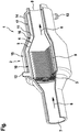
- Figure is a schematic partial sectional view of an exhaust gas purification device having an exhaust filter, a heat exchanger and a heat insulation.
- the figure shows a schematic partial sectional view of an exhaust gas purification device 1.
- This has an exhaust gas filter 2, which in turn has an exhaust filter body 3.
- an exhaust filter body 3 In the exhaust filter body 3, a plurality of flow channels not shown in detail here is formed.
- the exhaust filter body is arranged in an exhaust filter housing 4 and is enclosed by a housing wall 5 of the exhaust filter housing 4.
- the housing wall 5 With regard to a flow direction of exhaust gas flowing through the exhaust gas purification device 1, the housing wall 5 preferably comprises the exhaust gas filter body 3 completely in the circumferential direction.
- the flow direction of the exhaust gas is indicated by the arrows 6.
- an exhaust gas inlet 7 and an exhaust gas outlet 8 are formed in the exhaust filter housing 4, an exhaust gas inlet 7 and an exhaust gas outlet 8 are formed.
- the exhaust gas flows through the exhaust gas inlet 7 into the exhaust gas filter housing 4 and out of the exhaust gas filter housing 4 through the exhaust gas outlet 8.
- the exhaust gas filter body 3 is arranged, namely in such a way that the entire exhaust gas flowing through the exhaust gas filter 2 passes through the exhaust gas filter body 3 or its flow channels.
- the exhaust filter body 3 may be sealingly attached to the housing wall 5, for example via a fastening element 9.
- the fastening element 9 consists for example of an elastic material.
- a heat exchanger 10 is arranged on the exhaust filter body 3 side facing away from the housing wall 5.
- the heat exchanger 10 is viewed in the flow direction of the exhaust gas at least partially in overlap with the exhaust filter body 3 before.
- the heat exchanger 10 extends beyond the exhaust filter body 3 both upstream and downstream.
- the heat exchanger 10 is particularly preferably located closer to the exhaust gas outlet 8 than to the exhaust gas inlet 7.
- a reverse configuration may also be provided.
- the heat exchanger 10 preferably has a plurality of fluid ports 12 and 13, wherein one of the fluid ports 12 and 13 serves as a fluid inlet and another of the fluid ports 12 and 13 as a fluid outlet.
- the coolant can be supplied to the heat exchanger 10 through the fluid inlet and removed through the fluid outlet.
- the heat exchanger 10 or its fluid space 11 is associated with a cooling circuit for cooling a drive unit of a drive device, wherein the exhaust gas purification device 1 is part of the drive device.
- At least one flow guiding element and / or at least one surface enlarging element can be arranged in the fluid space 11.
- the at least one flow guide element is for example arranged and / or formed such that through the fluid inlet supplied fluid is passed to the fluid outlet.
- the fluid inlet and the fluid outlet are spaced apart in the axial direction, in particular in the axial direction at opposite ends of the fluid space 11.
- the flow guide element is now intended to guide the supplied fluid in a spiral shape in such a way that it is deflected by at least 180 ° in the circumferential direction on the way to the fluid outlet.
- a deflection of at least 360 °, at least 720 °, at least 1080 °, at least 1440 ° or at least 1800 ° may be provided.
- the flow guide element in the fluid space 11 forms a flow channel which starts at the fluid inlet and ends at the fluid outlet and has several turns in the circumferential direction, in particular at least 2, at least 3, at least 4 or at least 5.
- the surface enlargement element is provided in the fluid space 11. This is attached to the housing wall 5 and passes through the fluid space 11 in the radial direction preferably only partially. Alternatively, of course, a complete penetration can be provided. In this case, the surface enlarging element is additionally designed as a flow guide element.
- At least one of the exhaust gas flowing and / or overflowed Abgasleitelement is arranged downstream of the exhaust filter body 3 in the exhaust filter housing 4.
- This is preferably designed such that it directs exhaust gas in the radial direction outwards in the direction of the housing wall 5.
- the exhaust gas a comparatively large amount of heat can be withdrawn.
- this is the exhaust gas guide of the surface enlargement.
- the exhaust gas guide element consists for example of a heat-conducting material and is heat-conducting with the housing wall 5 connected. The exhaust gas guide element extends in each case starting from the housing wall 5, starting in the radial direction inwards.
- both the exhaust filter housing 4 and the heat exchanger 10 are encompassed in each case at least partially by a heat insulation 14.
- the heat insulation 14 extends both upstream and downstream beyond the heat exchanger 10 and is thus on both sides of the heat exchanger 10 to the housing wall 5 at.
- the thermal insulation 14 extends from the exhaust gas inlet 7 to the exhaust gas outlet 8.
- the heat exchanger 10 has different heat exchanger regions 15, 16 and 17. Each of these heat transfer areas 15, 16 and 17 is adapted to the exhaust filter housing 4 shape and dimension.
- the heat transfer regions 15 and 17, for example, cylindrical, in particular circular-cylindrical configured, while the heat transfer region 16 is conical.
- the heat supplied to the exhaust filter body 3 by means of an electric heater, not shown here, is supplied to at least one other device, in particular another vehicle device, after reaching an operating temperature through the exhaust filter body 3.
- the exhaust filter body 3 is further heated by the heater.
- the other vehicle device may be, for example, the drive unit, a passenger compartment and / or an energy store or a heat store.
Landscapes
- Engineering & Computer Science (AREA)
- Chemical & Material Sciences (AREA)
- Combustion & Propulsion (AREA)
- Mechanical Engineering (AREA)
- General Engineering & Computer Science (AREA)
- Exhaust Gas After Treatment (AREA)
- Processes For Solid Components From Exhaust (AREA)
- Filtering Of Dispersed Particles In Gases (AREA)
Abstract
Die Erfindung betrifft eine Abgasreinigungseinrichtung (1) mit einem Abgasfilter (2), der einen in einem Abgasfiltergehäuse (4) angeordneten, eine Vielzahl von Strömungskanälen ausbildenden Abgasfilterkörper (3) aufweist, und einer elektrischen Heizeinrichtung zur Beheizung des Abgasfilterkörpers (3), wobei der Abgasfilterkörper (3) von einer Gehäusewand (5) des Abgasfiltergehäuses (4) eingefasst ist, dabei ist vorgesehen, dass auf der dem Abgasfilterkörper (3) abgewandten Seite der Gehäusewand (5) ein Wärmeübertrager (10) angeordnet ist, der über die Gehäusewand (5) mit dem Abgasfilterkörper (3) in Wärmeübertragungsverbindung steht. Die Erfindung betrifft weiterhin eine Antriebseinrichtung mit einem abgaserzeugenden Antriebsaggregat und einer Abgasreinigungseinrichtung (1) zur Reinigung des von dem Antriebsaggregat erzeugten Abgases sowie ein Verfahren zum Betreiben einer Antriebseinrichtung.The invention relates to an exhaust gas purification device (1) having an exhaust gas filter (2) which has an exhaust gas filter body (3) arranged in an exhaust gas filter housing (4) and forming a plurality of flow channels, and an electric heating device for heating the exhaust gas filter body (3) Exhaust filter body (3) by a housing wall (5) of the exhaust filter housing (4) is enclosed, it is provided that on the exhaust filter body (3) facing away from the housing wall (5), a heat exchanger (10) is arranged, via the housing wall ( 5) is in heat transfer communication with the exhaust filter body (3). The invention further relates to a drive device with a waste-gas generating drive unit and an exhaust gas purification device (1) for cleaning the exhaust gas generated by the drive unit and a method for operating a drive device.
Description
Die Erfindung betrifft eine Abgasreinigungseinrichtung mit einem Abgasfilter, der einen in einem Abgasfiltergehäuse angeordneten, eine Vielzahl von Strömungskanälen ausbildenden Abgasfilterkörper aufweist, und einer elektrischen Heizeinrichtung zur Beheizung des Abgasfilterkörpers, wobei der Abgasfilterkörper von einer Gehäusewand des Abgasfiltergehäuses eingefasst ist. Die Erfindung betrifft weiterhin eine Antriebseinrichtung mit einem abgaserzeugenden Antriebsaggregat und einer Abgasreinigungseinrichtung zur Reinigung des von dem Antriebsaggregat erzeugten Abgases sowie ein Verfahren zum Betreiben einer Antriebseinrichtung.The invention relates to an exhaust gas purification device with an exhaust gas filter, which has arranged in an exhaust filter housing, a plurality of flow channels forming exhaust filter body, and an electric heater for heating the exhaust filter body, wherein the exhaust filter body is enclosed by a housing wall of the exhaust filter housing. The invention further relates to a drive device with a waste-gas generating drive unit and an exhaust gas purification device for cleaning the exhaust gas generated by the drive unit and a method for operating a drive device.
Die Abgasreinigungseinrichtung dient der Reinigung von Abgas, welche von dem abgaserzeugenden Antriebsaggregat, welches beispielsweise Bestandteil der Antriebseinrichtung ist, während seines Betriebs erzeugt werden. Insbesondere ist dabei eine Umwandlung von in dem Abgas enthaltenen Schadstoffen in unschädliche oder zumindest unschädlichere Stoffe vorgesehen. Der Abgasfilter verfügt über den Abgasfilterkörper, welcher die eigentliche filternde und/oder katalytische Wirkung auf das Abgas beziehungsweise die in diesem enthaltenen Schadstoffe ausübt. Der Abgasfilterkörper besteht beispielsweise aus einem Wabenkörper, in dem die Vielzahl von Strömungskanälen vorliegt. Der Wabenkörper besteht bevorzugt aus Keramik, beispielsweise Cordierit. Auch andere Materialien können jedoch zur Herstellung des Wabenkörpers verwendet werden.The exhaust gas purification device is used to purify exhaust gas, which is generated by the exhaust gas generating drive unit, which is for example part of the drive device, during its operation. In particular, a conversion of pollutants contained in the exhaust gas into innocuous or at least less harmful substances is provided. The exhaust gas filter has the exhaust filter body, which exerts the actual filtering and / or catalytic effect on the exhaust gas or the pollutants contained therein. The exhaust filter body consists for example of a honeycomb body, in which the plurality of flow channels is present. The honeycomb body is preferably made of ceramic, for example cordierite. However, other materials may be used to make the honeycomb body.
Der Abgasfilterkörper kann - im Falle einer zumindest teilweisen Ausgestaltung des Abgasfilters als Abgaskatalysator - mit einer katalytischen Beschichtung versehen sein. Beispielsweise liegt diese Beschichtung in Form eines sogenannten Wash Coats vor, welcher zur Vergrößerung einer effektiven Oberfläche eine hohe Rauheit, insbesondere eine höhere Rauheit als der Abgasfilterkörper selbst, aufweist. Bevorzugt ist in der Beschichtung wenigstens ein katalytisch wirksames Element, beispielsweise ein Edelmetall, eingelagert. Beispielsweise kommen hier eines oder mehrere der folgenden Edelmetalle zum Einsatz: Platin, Rhodium und Palladium. Der Abgaskatalysator kann beispielsweise als Dreiwegekatalysator oder als Vierwegekatalysator ausgestaltet sein. Alternativ oder zusätzlich kann der Abgasfilter jedoch auch als Partikelfilter ausgestaltet sein oder zumindest einen solchen aufweisen. Der Partikelfilter ist zum Beispiel ein Ottopartikelfilter oder ein Dieselpartikelfilter.The exhaust filter body may be provided with a catalytic coating in the case of an at least partial embodiment of the exhaust gas filter as exhaust gas catalytic converter. For example, this coating is in shape a so-called washcoat, which for increasing an effective surface has a high roughness, in particular a higher roughness than the exhaust filter body itself. Preferably, at least one catalytically active element, for example a noble metal, is incorporated in the coating. For example, here one or more of the following precious metals are used: platinum, rhodium and palladium. The exhaust gas catalyst can be configured, for example, as a three-way catalyst or as a four-way catalyst. Alternatively or additionally, however, the exhaust gas filter may also be configured as a particle filter or at least have such a filter. The particulate filter is, for example, a gasoline particulate filter or a diesel particulate filter.
Der Abgasfilterkörper ist in dem Abgasfiltergehäuse angeordnet. Das Abgasfiltergehäuse dient insbesondere der Strömungsführung der Abgasströmung. Insoweit weist das Abgasfiltergehäuse einen Abgaseinlass und einen Abgasauslass auf. Durch den Abgaseinlass kann Abgas in das Abgasfiltergehäuse austreten. Nachfolgend durchströmt es das Abgasfiltergehäuse und tritt durch den Abgasauslass aus dem Abgasfiltergehäuse aus. In dem Strömungsweg zwischen dem Abgaseinlass und dem Abgasauslass ist der Abgasfilterkörper in dem Abgasfiltergehäuse angeordnet, Dies ist dabei derart vorgesehen, dass das Abgas bei der Durchströmung des Abgasfiltergehäuses, also auf dem Strömungsweg zwischen dem Abgaseinlass und dem Abgasauslass, durch den Abgasfilterkörper beziehungsweise dessen Strömungskanäle hindurchtritt. Bevorzugt ist dabei der Abgasfilterkörper derart in dem Abgasfiltergehäuse angeordnet, dass das gesamte durch den Abgaseinlass in das Abgasfiltergehäuse eintretende Abgas den Abgasfilterkörper beziehungsweise seine Strömungskanäle durchströmt.The exhaust filter body is disposed in the exhaust filter housing. The exhaust gas filter housing is used in particular for the flow guidance of the exhaust gas flow. In that regard, the exhaust filter housing has an exhaust gas inlet and an exhaust gas outlet. Exhaust gas can escape into the exhaust gas filter housing through the exhaust gas inlet. Subsequently, it flows through the exhaust filter housing and exits through the exhaust outlet from the exhaust filter housing. In the flow path between the exhaust gas inlet and the exhaust gas outlet of the exhaust filter body is arranged in the exhaust filter housing, this is provided such that the exhaust gas passes through the exhaust filter body or its flow channels in the flow through the exhaust filter housing, ie on the flow path between the exhaust inlet and the exhaust gas outlet , In this case, the exhaust filter body is preferably arranged in the exhaust filter housing such that the entire exhaust gas entering the exhaust gas filter housing through the exhaust gas inlet flows through the exhaust filter body or its flow channels.
Der Abgasfilterkörper ist hierzu vorzugsweise von der Gehäusewand des Abgasfiltergehäuses eingefasst. Beispielsweise umgreift die Gehäusewand den Abgasfilterkörper in Umfangsrichtung bezüglich einer Längsmittelachse des Abgasfilterkörpers beziehungsweise einer Durchströmungsrichtung des Abgasfiltergehäuses vollständig. Bevorzugt begrenzt die Gehäusewand den Abgaseinlass und/oder über den Abgasauslass. Besonders bevorzugt sind der Abgaseinlass und der Abgasauslass jeweils als randgeschlossene Öffnung in der Gehäusewand ausgebildet. Die Gehäusewand sorgt insoweit für eine Strömungsführung des das Abgasfiltergehäuse durchströmenden Abgases von dem Abgaseinlass bis hin zu dem Abgasauslass.The exhaust filter body is for this purpose preferably enclosed by the housing wall of the exhaust filter housing. For example, encompasses the housing wall the exhaust filter body in the circumferential direction with respect to a longitudinal center axis of the exhaust filter body or a flow direction of the exhaust filter housing completely. The housing wall preferably limits the exhaust gas inlet and / or via the exhaust gas outlet. Particularly preferably, the exhaust gas inlet and the exhaust gas outlet are each formed as an edge-closed opening in the housing wall. The housing wall thus ensures a flow guidance of the exhaust gas flowing through the exhaust filter housing from the exhaust gas inlet to the exhaust gas outlet.
Der Abgasfilter weist seine höchsten Umwandlungsraten für die Schadstoffe bei einer bestimmten Betriebstemperatur auf. Insbesondere bei Temperaturen unterhalb dieser Betriebstemperatur sind die Umwandlungsraten äußerst niedrig, sodass die Abgase ohne Umwandlung den Abgasfilter durchströmen können, also zusammen mit dem Abgas aus dem Abgasauslass des Abgasfilters austreten. Um dies zu vermeiden, ist die elektrische Heizeinrichtung vorgesehen. Diese dient der Beheizung des Abgasfilterkörpers, um diesen möglichst rasch auf die Betriebstemperatur zu bringen. Bevorzugt erfolgt dies bereits vor einem Betriebsbeginn des abgaserzeugenden Antriebsaggregats, also bevor der Abgasfilter von Abgas durchströmt wird. Besonders bevorzugt wird der Abgasfilterkörper mittels der Heizeinrichtung bereits auf seine Betriebstemperatur gebracht, bevor das abgaserzeugende Antriebsaggregat in Betrieb genommen wird, also Abgas erzeugt wird.The exhaust filter has its highest conversion rates for the pollutants at a certain operating temperature. In particular, at temperatures below this operating temperature, the conversion rates are extremely low, so that the exhaust gases can flow through without conversion the exhaust gas filter, thus emerge together with the exhaust gas from the exhaust gas outlet of the exhaust gas filter. To avoid this, the electric heater is provided. This serves to heat the exhaust filter body in order to bring it as quickly as possible to the operating temperature. This is preferably done before the start of operation of the exhaust-generating drive unit, ie before the exhaust gas filter is flowed through by exhaust gas. Particularly preferably, the exhaust filter body is already brought to its operating temperature by means of the heater before the exhaust-generating drive unit is put into operation, that is, exhaust gas is generated.
Das Beheizen des Abgasfilterkörpers mittels der elektrischen Heizeinrichtung ist äußerst energieaufwendig. Dies gilt umso mehr, wenn das abgaserzeugende Antriebsaggregat lediglich temporär betrieben wird, wie es beispielsweise bei einer Hybridantriebseinrichtung eines Kraftfahrzeugs der Fall sein kann. In diesem Fall muss der Abgasfilterkörper während eines Betriebs des Kraftfahrzeugs bei abgeschaltetem abgaserzeugendem Antriebsaggregat durchgehend beheizt werden, weil die Einrichtung jederzeit gestartet werden kann.The heating of the exhaust filter body by means of the electric heater is extremely energy consuming. This is all the more true if the exhaust-generating drive unit is operated only temporarily, as may be the case for example in a hybrid drive device of a motor vehicle. In this case, the exhaust filter body must during operation of the motor vehicle with switched off gas generating drive unit be heated continuously, because the device can be started at any time.
Es ist Aufgabe der Erfindung, eine Abgasreinigungseinrichtung vorzuschlagen, welche gegenüber bekannten Abgasreinigungseinrichtungen Vorteile aufweist, insbesondere trotz vorsehen der elektrischen Heizeinrichtung zur Beheizung des Abgasfilterkörpers einen energieeffizienten Betrieb der Abgasreinigungseinrichtung ermöglicht.It is an object of the invention to propose an exhaust gas purification device, which has advantages over known exhaust gas purification devices, in particular despite providing the electric heater for heating the exhaust filter body allows energy-efficient operation of the exhaust gas purification device.
Dies wird erfindungsgemäß mit einer Abgasreinigungseinrichtung mit den Merkmalen des Anspruchs 1 erreicht. Dabei ist vorgesehen, dass auf der dem Abgasfilterkörper abgewandten Seite der Gehäusewand ein Wärmeübertrager angeordnet ist, der über die Gehäusewand mit dem Abgasfilterkörper in Wärmeübertragungsverbindung steht.This is achieved according to the invention with an exhaust gas purification device having the features of claim 1. It is provided that a heat exchanger is arranged on the side facing away from the exhaust filter body side of the housing wall, which is in heat transfer connection via the housing wall with the exhaust filter body.
Die Abgasreinigungseinrichtung weist also zusätzlich zu dem Abgasfilter den Wärmeübertrager auf. Dieser ist derart ausgestaltet, dass er dem Abführen von Wärme von dem Abgasfilterkörper dient. Entsprechend ist er derart angeordnet, dass er mit dem Abgasfilterkörper in Wärmeübertragungsverbindung steht. Die Wärmeübertragungsverbindung liegt über die Gehäusewand vor. Hierzu besteht die Gehäusewand vorzugsweise aus einem wärmeleitenden Material, insbesondere in einem Bereich der Gehäusewand, an welchem der Abgasfilterkörper einerseits und der Wärmeübertrager andererseits anliegen.The exhaust gas purification device therefore has the heat exchanger in addition to the exhaust gas filter. This is designed such that it serves to dissipate heat from the exhaust filter body. Accordingly, it is arranged such that it is in heat transfer communication with the exhaust filter body. The heat transfer connection is above the housing wall. For this purpose, the housing wall preferably consists of a thermally conductive material, in particular in a region of the housing wall, against which the exhaust filter body on the one hand and the heat exchanger on the other.
Hierbei kann es auch vorgesehen sein, dass die Gehäusewand aus mehreren Teilabschnitten besteht, welche aus unterschiedlichen Materialien bestehen. Beispielsweise besteht die Gehäusewand in einem Teilbereich, an welchem sowohl der Wärmeübertrager als auch der Abgasfilterkörper anliegt, aus einem Material, welches eine höhere Wärmeleitfähigkeit aufweist als ein Material, aus welchem wenigstens ein weiterer Teilbereich die Gehäusewand besteht, der abseits des Wärmeübertragers und des Abgasfilterkörpers vorliegt, also von diesen beabstandet ist.It can also be provided that the housing wall consists of several sections, which consist of different materials. For example, the housing wall is made of a material which has a higher thermal conductivity than a partial region in which both the heat exchanger and the exhaust filter body are present Material from which at least one further sub-area consists of the housing wall, which is present away from the heat exchanger and the exhaust filter body, that is spaced therefrom.
Zusätzlich oder alternativ kann es vorgesehen sein, in der Gehäusewand wenigstens ein Wärmeleitelement anzuordnen, über welches der Abgasfilterkörper in Wärmeübertragungsverbindung mit dem Wärmeübertrager steht. Ein solches Wärmeleitelement kann beispielsweise ein Wärmerohr, beispielsweise eine Heatpipe oder ein Thermosiphon, sein. Ist eine derartige Wärmeleiteinrichtung vorgesehen, so kann selbstverständlich die Gehäusewand durchgehend materialeinheitlich sein, also durchgängig aus demselben Material bestehen.Additionally or alternatively, it can be provided to arrange at least one heat-conducting element in the housing wall, via which the exhaust-gas filter body is in heat-transfer connection with the heat exchanger. Such a heat-conducting element can be, for example, a heat pipe, for example a heat pipe or a thermosyphon. If such a heat conduction device is provided, it goes without saying that the housing wall can be made of the same material throughout, that is, consist continuously of the same material.
Der Wärmeübertrager ist auf der dem Abgasfilterkörper abgewandten Seite der Gehäusewand angeordnet. Insbesondere soll der Wärmeübertrager nicht direkt von Abgas angeströmt und/oder überströmt sein. Vielmehr soll der Wärmeübertrager außerhalb von abgasführenden Bereichen des Abgasfiltergehäuses vorliegen. Entsprechend dient der Wärmeübertrager schlussendlich dem Abführen von Wärme von dem Abgasfilterkörper, nicht jedoch dem direkten Entnehmen von Wärme aus dem Abgas. Dies ist lediglich mittelbar über den Abgasfilterkörper vorgesehen.The heat exchanger is arranged on the side facing away from the exhaust filter body side of the housing wall. In particular, the heat exchanger should not be directly flowed by exhaust gas and / or overflowed. Rather, the heat exchanger should be present outside exhaust-carrying areas of the exhaust filter housing. Accordingly, the heat exchanger ultimately serves the removal of heat from the exhaust filter body, but not the direct removal of heat from the exhaust gas. This is only provided indirectly via the exhaust filter body.
Die mittels des Wärmeübertragers dem Abgasfilterkörper entnommene Wärme kann einer beliebigen anderen Einrichtung zugeführt werden. Beispielsweise ist der Wärmeübertrager an einen Kühlkreislauf angeschlossen, welcher der Temperierung beziehungsweise Kühlung eines Antriebsaggregats der Antriebseinrichtung dient. Zusätzlich oder alternativ kann die Wärme zum Temperieren eines Fahrgastraums des Kraftfahrzeugs herangezogen werden. Das bedeutet, dass zwar einerseits der Abgasfilterkörper mittels der elektrischen Heizeinrichtung beheizt wird, die hierzu verwendete Energie jedoch auch für andere Zwecke eingesetzt, insbesondere wenn der Abgasfilterkörper bereits seine Betriebstemperatur erreicht hat.The heat removed by the heat exchanger the exhaust filter body heat can be supplied to any other device. For example, the heat exchanger is connected to a cooling circuit, which serves for the temperature control or cooling of a drive unit of the drive device. Additionally or alternatively, the heat can be used for tempering a passenger compartment of the motor vehicle. This means that, on the one hand, the exhaust filter body is heated by means of the electric heater, but the energy used for this purpose also used for other purposes, especially when the exhaust filter body has already reached its operating temperature.
Zudem wird durch den Wärmeübertrager die thermische Masse des Abgasfilters beziehungsweise der Abgasreinigungseinrichtung vergrößert, sodass ein Auskühlen des Abgasfilters, insbesondere ausgehend von seiner Betriebstemperatur, im Vergleich mit herkömmlichen Abgasreinigungseinrichtungen verzögert ist. Auch ist es möglich, den Wärmeübertrager zum Kühlen des Abgases zu verwenden. Beispielsweise wird dem Abgas mittels des Wärmeübertragers eine bestimmte Wärmemenge entzogen, die derart gewählt ist, dass stromabwärts des Wärmeübertragers das Abgas eine bestimmte Abgastemperatur aufweist oder diese zumindest nicht überschreitet. Dies kann beispielsweise vorgesehen sein, wenn das Abgas stromabwärts der Abgasreinigungseinrichtung eine Abgasleitung durchströmt, die im Bereich eines Energiespeichers für elektrische Energie, insbesondere einer Batterie, beispielsweise einer Hochvoltbatterie, vorliegt oder durch diesen/diese verläuft. Auch wenn die Abgasleitung durch einen Tunnel verläuft, kann die beschriebene Vorgehensweise angewandt werden.In addition, the thermal mass of the exhaust gas filter or the exhaust gas purification device is increased by the heat exchanger, so that a cooling of the exhaust gas filter, in particular starting from its operating temperature, is delayed in comparison with conventional exhaust gas purification devices. It is also possible to use the heat exchanger for cooling the exhaust gas. For example, the exhaust gas by means of the heat exchanger, a certain amount of heat withdrawn, which is chosen such that downstream of the heat exchanger, the exhaust gas has a certain exhaust gas temperature or at least does not exceed. This can be provided, for example, when the exhaust gas downstream of the exhaust gas cleaning device flows through an exhaust gas line which is present in the region of an energy store for electrical energy, in particular a battery, for example a high-voltage battery, or passes through it. Even if the exhaust pipe passes through a tunnel, the described procedure can be used.
Im Rahmen einer weiteren Ausgestaltung der Erfindung ist vorgesehen, dass in axialer Richtung bezüglich einer Längsmittelachse des Abgasfilterkörpers gesehen der Wärmeübertrager mehrere jeweils an der Gehäusewand anliegende Wärmeübertragerbereiche aufweist, die voneinander verschiedene Innenabmessungen aufweisen. Beispielsweise setzt sich das Abgasfiltergehäuse beziehungsweise die Gehäusewand aus mehreren Teilbereichen zusammen. Vorzugsweise grenzen diese Teilbereiche in axialer Richtung bezüglich der Längsmittelachse des Abgasfilterkörpers gesehen aneinander an. Selbstverständlich können einige der Teilbereiche auch voneinander beabstandet angeordnet sein. Die Teilbereiche des Abgasfiltergehäuses können voneinander verschiedene Außenabmessungen aufweisen.As part of a further embodiment of the invention, it is provided that viewed in the axial direction with respect to a longitudinal central axis of the exhaust filter body, the heat exchanger has a plurality of heat transfer regions respectively adjacent to the housing wall, which have different inner dimensions from each other. For example, the exhaust filter housing or the housing wall is composed of several subregions. Preferably, these partial regions adjoin one another in the axial direction with respect to the longitudinal central axis of the exhaust filter body. Of course, some of the sections may also be spaced apart from each other. The portions of the exhaust filter housing may have different outer dimensions.
Der Wärmeübertrager ist an das Abgasfiltergehäuse beziehungsweise die Teilbereiche form- und/oder abmessungsangepasst, insbesondere derart, dass er von außen an ihm beziehungsweise ihnen anliegt. Entsprechend weist der Wärmeübertrager mehrere voneinander verschiedene Wärmeübertragerbereiche auf, welche über voneinander abweichende Innenabmessungen verfügen. Es kann dabei vorgesehen sein, dass der Wärmeübertrager in axialer Richtung größere Abmessungen aufweist als der Abgasfilterkörper. Insbesondere erstreckt sich der Wärmeübertrager in stromabwärtige Richtung bezüglich der Durchströmungsrichtung des Abgases durch den Abgasfilter über den Abgasfilterkörper hinaus. Alternativ kann es selbstverständlich vorgesehen sein, dass der Wärmeübertrager auf seiner stromabwärts gelegenen Seite mit dem Abgasfilterkörper fluchtet beziehungsweise stromaufwärts von diesem endet.The heat exchanger is adapted to the exhaust gas filter housing or the subregions in shape and / or dimensions, in particular in such a way that it rests against it or against it from the outside. Accordingly, the heat exchanger on a plurality of different heat transfer areas, which have different inner dimensions. It may be provided that the heat exchanger has larger dimensions in the axial direction than the exhaust filter body. In particular, the heat exchanger extends in the downstream direction with respect to the direction of flow of the exhaust gas through the exhaust gas filter beyond the exhaust filter body. Alternatively, it may of course be provided that the heat exchanger is aligned on its downstream side with the exhaust filter body or ends upstream of this.
Eine weitere Ausgestaltung der Erfindung sieht vor, dass zumindest einer der Wärmeübertragerbereiche eine zylindrische, insbesondere kreiszylindrische, Innenumfangsfläche und/oder zumindest ein weiterer der Wärmeübertragerbereiche eine konische Innenumfangsfläche aufweist. Grundsätzlich können die Wärmeübertagebereiche eine beliebige Form aufweisen. Bevorzugt ist jedoch einer der Wärmeübertragerbereiche zylindrisch und ein anderer der Wärmeübertragerbereiche konisch. Dies gilt entsprechend auch für die Teilabschnitte der Gehäusewand beziehungsweise des Abgasfiltergehäuses, an welchen der jeweilige Wärmeübertragerbereich anliegt.A further embodiment of the invention provides that at least one of the heat exchanger regions has a cylindrical, in particular circular-cylindrical, inner peripheral surface and / or at least one further of the heat-exchanger regions has a conical inner circumferential surface. In principle, the heat transfer areas can have any desired shape. However, one of the heat exchanger regions is preferably cylindrical and another of the heat exchanger regions is conical. This also applies correspondingly to the subsections of the housing wall or of the exhaust gas filter housing to which the respective heat exchanger area rests.
Beispielsweise ist es vorgesehen, dass das Abgasfiltergehäuse in Durchströmungsrichtung des Abgases gesehen zunächst einen zylindrischen Teilbereich aufweist, an welchen sich ein konischer Teilbereich anschließt, sodass sich der Durchströmungsquerschnitt in Strömungsrichtung vergrößert. An den konischen Teilbereich schließt sich wiederum ein zylindrischer Teilbereich an, in welchem der Abgasfilterkörper vorliegt. Stromabwärts des Abgasfilterkörpers liegt erneut ein konischer Teilbereich vor, in welchem sich der Durchströmungsquerschnitt in Strömungsrichtung verkleinert. An diesen konischen Teilbereich kann sich wiederum ein zylindrischer Teilbereich anschließen. In dem zuerst genannten Teilbereich kann der Abgaseinlass und in dem zuletzt genannten Teilbereich der Abgasauslass vorliegen.For example, it is provided that, viewed in the direction of flow of the exhaust gas, the exhaust gas filter housing initially has a cylindrical subarea, to which a conical subarea adjoins, so that the throughflow cross section in the flow direction increases. The conical portion is in turn closed by a cylindrical portion in which the exhaust filter body is present. Downstream of the exhaust filter body is again a conical portion, in which the flow cross-section decreases in the flow direction. In turn, a cylindrical section can follow this conical subregion. In the first-mentioned subarea, the exhaust gas inlet and in the last-mentioned subarea of the exhaust gas outlet may be present.
Schließlich kann im Rahmen einer weiteren bevorzugten Ausgestaltung vorgesehen sein, dass das Abgasfiltergehäuse und/oder der Wärmeübertrager wenigstens bereichsweise von einer, insbesondere wenigstens einerseits des Wärmeübertragers oder beiderseits des Wärmeübertragers an der Gehäusewand anliegenden, Wärmeisolierung umgriffen ist. Die Wärmeisolierung dient der thermischen Isolierung der Abgasreinigungseinrichtung, sodass möglichst wenig Wärme des Abgasfilterkörpers verloren geht, insbesondere falls er nicht von Abgas durchströmt ist. Die Wärmeisolierung umgreift das Abgasfiltergehäuse und/oder den Wärmeübertrager wenigstens bereichsweise, insbesondere in Umfangsrichtung bezüglich der Längsmittelachse des Abgasfilterkörpers vollständig. Bevorzugt liegt die Wärmeisolierung hierbei an einer Außenumfangsfläche des Abgasfiltergehäuses und/oder des Wärmeübertragers an.Finally, it can be provided within the scope of a further preferred embodiment that the exhaust gas filter housing and / or the heat exchanger is encompassed at least partially by one, in particular at least on the one hand of the heat exchanger or on both sides of the heat exchanger to the housing wall, heat insulation. The thermal insulation is used for thermal insulation of the exhaust gas purification device, so that as little heat of the exhaust filter body is lost, especially if it is not flowed through by exhaust gas. The heat insulation surrounds the exhaust filter housing and / or the heat exchanger at least in regions, in particular in the circumferential direction with respect to the longitudinal central axis of the exhaust filter body completely. The heat insulation is preferably applied to an outer peripheral surface of the exhaust filter housing and / or the heat exchanger.
Weiter bevorzugt erstreckt sich die Wärmeisolierung in Strömungsrichtung wenigstens einseitig, bevorzugt jedoch beidseitig, über den Wärmeübertrager hinaus. Das bedeutet, dass die Wärmeisolierung in Strömungsrichtung durchgehend an dem Wärmeübertrager anliegt und beidseitig des Wärmeübertragers an dem Abgasfiltergehäuse anliegt. Es kann hierbei vorgesehen sein, dass sich die Wärmeisolierung in Strömungsrichtung von dem Abgaseinlass bis hin zu dem Abgasauslass des Abgasfiltergehäuses erstreckt.More preferably, the heat insulation extends in the flow direction at least on one side, but preferably on both sides, beyond the heat exchanger addition. This means that the thermal insulation rests continuously in the flow direction on the heat exchanger and rests on both sides of the heat exchanger to the exhaust filter housing. It may be provided here that the heat insulation extends in the flow direction from the exhaust gas inlet to the exhaust gas outlet of the exhaust gas filter housing.
Die Erfindung betrifft weiterhin eine Antriebseinrichtung mit einem abgaserzeugenden Antriebsaggregat und einer Abgasreinigungseinrichtung zur Reinigung des von dem Antriebsaggregat erzeugten Abgases, insbesondere einer Abgasreinigungseinrichtung gemäß den vorstehenden Ausführungen, wobei die Abgasreinigungseinrichtung über einen Abgasfilter, der einen in einem Abgasfiltergehäuse angeordneten, eine Vielzahl von Strömungskanälen ausbildenden Abgasfilterkörper aufweist, und über eine elektrische Heizeinrichtung zur Beheizung des Abgasfilterkörpers verfügt, wobei der Abgasfilterkörper von einer Gehäusewand des Abgasfiltergehäuses eingefasst ist. Dabei ist vorgesehen, dass auf der dem Abgasfilterkörper abgewandten Seite der Gehäusewand ein Wärmeübertrager angeordnet ist, der über die Gehäusewand mit dem Abgasfilterkörper in Wärmeübertragungsverbindung steht.The invention further relates to a drive device with a waste gas generating drive unit and an exhaust gas purification device for cleaning the exhaust gas generated by the drive unit, in particular an exhaust gas purification device according to the above embodiments, wherein the exhaust gas purification device via an exhaust filter, which arranged in an exhaust filter housing, a plurality of flow channels forming exhaust filter body has, and has an electric heater for heating the exhaust filter body, wherein the exhaust filter body is enclosed by a housing wall of the exhaust filter housing. It is provided that a heat exchanger is arranged on the side facing away from the exhaust filter body side of the housing wall, which is in heat transfer connection via the housing wall with the exhaust filter body.
Auf die Vorteile einer derartigen Ausgestaltung der Abgasreinigungseinrichtung beziehungsweise der Antriebseinrichtung wurde bereits hingewiesen. Sowohl die Antriebseinrichtung als auch die Abgasreinigungseinrichtung können gemäß den vorstehenden Ausführungen weitergebildet sein, sodass insoweit auf diese verwiesen wird.The advantages of such an embodiment of the exhaust gas purification device or the drive device has already been pointed out. Both the drive device and the exhaust gas purification device can be developed further in accordance with the above explanations, so that reference is made to this extent.
Eine weitere bevorzugte Ausgestaltung der Erfindung sieht einen Kühlkreislauf zur Temperierung des Antriebsaggregats vor, der strömungstechnisch an den Wärmeübertrager angeschlossen ist. Allgemein ausgedrückt dient der Kühlkreislauf der Temperierung des Antriebsaggregats, sodass er auch als Temperierkreislauf bezeichnet werden kann. Der Kühlkreislauf ist strömungstechnisch an den Wärmeübertrager angeschlossen, sodass in dem Kühlkreislauf zirkulierendes Kühlmittel zumindest zweitweise auch durch den Wärmeübertrager geführt wird. Auf diese Art und Weise kann die dem Abgasfilterkörper entnommene Wärme dem temperieren des Antriebsaggregats dienen, insbesondere falls dieses momentan nicht betrieben wird.A further preferred embodiment of the invention provides a cooling circuit for controlling the temperature of the drive unit, which is fluidically connected to the heat exchanger. Generally speaking, the cooling circuit of the temperature control of the drive unit, so that it can also be referred to as tempering. The cooling circuit is fluidically connected to the heat exchanger, so that in the cooling circuit circulating coolant is at least partially guided by the heat exchanger. In this way, the heat taken from the exhaust filter body heat can serve the tempering of the drive unit, in particular if this is currently not operated.
Eine Weiterbildung der Erfindung sieht vor, dass der Kühlkreislauf strömungstechnisch direkt oder über einen weiteren Wärmeübertrager an einen Fahrgastraumheizkreislauf angeschlossen ist. Der Fahrgastraumheizkreislauf dient der Temperierung eines Fahrgastraums des Kraftfahrzeugs. Es kann nun vorgesehen sein, dass das in dem Kühlkreislauf verwendete Kühlmittel unmittelbar dem Fahrgastraumheizkreislauf zugeführt wird. Alternativ kann zwischen dem Kühlkreislauf und dem Fahrgastraumheizkreislauf ein weiterer Wärmeübertrager vorliegen, sodass der Kühlkreislauf und der Fahrgastraumheizkreislauf fluidtechnisch voneinander entkoppelt sind.A development of the invention provides that the cooling circuit is fluidically connected directly or via a further heat exchanger to a passenger compartment heating. The passenger compartment heating circuit serves to control the temperature of a passenger compartment of the motor vehicle. It can now be provided that the coolant used in the cooling circuit is supplied directly to the passenger compartment heating circuit. Alternatively, another heat exchanger can be present between the cooling circuit and the passenger compartment heating circuit, so that the cooling circuit and the passenger compartment heating circuit are fluidly decoupled from one another.
Schließlich betrifft die Erfindung ein Verfahren zum Betreiben einer Antriebseinrichtung, insbesondere einer Antriebseinrichtung gemäß den vorstehenden Ausführungen, die ein abgaserzeugendes Antriebsaggregat und eine Abgasreinigungseinrichtung zur Reinigung des von dem Antriebsaggregat erzeugten Abgas aufweist, wobei die Abgasreinigungseinrichtung über einen Abgasfilter, der einen in einem Abgasfiltergehäuse angeordneten, eine Vielzahl von Strömungskanälen ausbildenden Abgasfilterkörper aufweist, und eine elektrische Heizeinrichtung zum Beheizen des Abgasfilterkörpers verfügt, wobei der Abgasfilterkörper von einer Gehäusewand des Abgasfiltergehäuses eingefasst ist. Dabei ist vorgesehen, dass auf der dem Abgasfilterkörper abgewandten Seite der Gehäusewand ein Wärmeübertrager angeordnet ist, der über die Gehäusewand mit dem Abgasfilterkörper in Wärmeübertragungsverbindung steht.Finally, the invention relates to a method for operating a drive device, in particular a drive device according to the preceding embodiments, which has a waste gas generating drive unit and an exhaust gas purification device for cleaning the exhaust gas generated by the drive unit, the exhaust gas purification device via an exhaust filter, which arranged in a exhaust gas filter housing, has a plurality of flow channels forming exhaust filter body, and has an electric heater for heating the exhaust filter body, wherein the exhaust filter body is enclosed by a housing wall of the exhaust filter housing. It is provided that a heat exchanger is arranged on the side facing away from the exhaust filter body side of the housing wall, which is in heat transfer connection via the housing wall with the exhaust filter body.
Hinsichtlich der Vorteile einer derartigen Ausgestaltung der Antriebseinrichtung sowie der entsprechenden Vorgehensweise sowie hinsichtlich möglicher Weiterbildungen der Antriebseinrichtung und des Verfahrens wird erneut auf die vorstehenden Ausführungen Bezug genommen.With regard to the advantages of such an embodiment of the drive device and the corresponding procedure and with regard to possible developments of the drive device and the method, reference is again made to the above statements.
Im Rahmen einer bevorzugten Ausführungsform der Erfindung kann vorgesehen sein, dass in einer ersten Betriebsart der Abgasfilterkörper mittels der Heizeinrichtung beheizt wird, wobei ein Kühlmittelstrom durch den Wärmeübertrager unterbrochen wird bis der Abgasfilterkörper eine Solltemperatur erreicht hat und nach dem Erreichen der Soltemperatur dem Abgasfilterkörper mittels des Wärmeübertragers Wärme entnommen wird, die nachfolgend zum Temperieren wenigstens einer Fahrzeugeinrichtung, insbesondere des Antriebsaggregats, eines Fahrgastraums und/oder eines Energiespeichers, verwendet wird. Im Rahmen der ersten Betriebsart soll insoweit der Abgasfilterkörper zunächst möglichst rasch auf seine Betriebstemperatur gebracht werden. Hierzu wird dem Abgasfilterkörper vorzugsweise Wärme mittels der Heizeinrichtung zugeführt. Zusätzlich kann ihm Wärme des Abgases zugeführt werden.In a preferred embodiment of the invention can be provided that in a first mode of the exhaust filter body is heated by the heater, wherein a flow of coolant is interrupted by the heat exchanger until the exhaust filter body has reached a target temperature and after reaching the sol temperature of the exhaust filter body by means of the heat exchanger Heat is taken, which is subsequently used for tempering at least one vehicle device, in particular the drive unit, a passenger compartment and / or an energy storage. In the context of the first operating mode, the exhaust filter body should first be brought to its operating temperature as quickly as possible. For this purpose, the exhaust filter body is preferably supplied with heat by means of the heating device. In addition, it can be supplied heat of the exhaust gas.
Hat der Abgasfilterkörper seine Solltemperatur erreicht, ist die Temperatur des Abgasfilterkörpers also größer oder gleich der Solltemperatur, so kann der Kühlmittelstrom durch den Wärmeübertrager freigegeben werden, sodass das Kühlmittel den Wärmeübertrager durchströmt. Mithilfe des Wärmeübertragers beziehungsweise dem Kühlmittel wird nachfolgend dem Abgasfilterkörper Wärme entnommen und der wenigstens einen Fahrzeugeinrichtung zugeführt.If the exhaust filter body has reached its setpoint temperature, that is, the temperature of the exhaust filter body is greater than or equal to the desired temperature, the coolant flow can be released by the heat exchanger, so that the coolant flows through the heat exchanger. Using the heat exchanger or the coolant heat is subsequently removed from the exhaust filter body and fed to at least one vehicle device.
Schließlich kann eine weitere Ausgestaltung der Erfindung vorsehen, dass in einer zweiten Betriebsart die Heizeinrichtung deaktiviert wird, wobei dem Abgasfilterkörper mittels des Wärmeübertragers Wärme zum Temperieren der wenigstens einen Fahrzeugeinrichtung entnommen wird. In der zweiten Betriebsart ist die Heizeinrichtung deaktiviert. Dem Abgasfilterkörper wird insoweit keine oder lediglich mittels des Abgases Wärme zugeführt. In jedem Fall kann dem Abgasfilterkörper jedoch mittels des Wärmeübertragers Wärme entnommen werden, die nachfolgend zum Temperieren der wenigstens einen Fahrzeugeinrichtung herangezogen wird.Finally, a further embodiment of the invention can provide that in a second operating mode, the heating device is deactivated, wherein the exhaust filter body heat is removed by means of the heat exchanger for tempering the at least one vehicle device. In the second mode, the heater is disabled. The exhaust filter body is supplied so far no or only by means of the exhaust heat. In any case, however, the exhaust filter body by means of the heat exchanger heat are removed, which is subsequently used for tempering the at least one vehicle device.
Beispielsweise ist eine derartige Vorgehensweise während des Betreibens des abgaserzeugenden Antriebsaggregats vorgesehen, sodass die in dem Abgas enthaltene Wärme zum Temperieren der Fahrzeugeinrichtung verwendet wird. Es kann jedoch auch vorgesehen sein, dem Abgasfilterkörper die Wärme zu entnehmen, obwohl ihm weder mittels der Heizeinrichtung noch über das Abgas Wärme zugeführt wird. In diesem Fall wird beispielsweise der Abgasfilterkörper als Wärmespeicher verwendet. Bevorzugt wird dies durchgeführt, wenn die Temperatur des Abgasfilterkörpers größer ist als die Solltemperatur. Die Solltemperatur kann hierbei der vorstehend erwähnten Betriebstemperatur entsprechen.For example, such a procedure is provided during the operation of the exhaust gas generating drive unit, so that the heat contained in the exhaust gas is used for controlling the temperature of the vehicle device. However, it can also be provided to remove the heat from the exhaust filter body, although heat is neither supplied to it by means of the heating device nor via the exhaust gas. In this case, for example, the exhaust filter body is used as a heat storage. This is preferably carried out when the temperature of the exhaust filter body is greater than the target temperature. The setpoint temperature may in this case correspond to the above-mentioned operating temperature.
Bevorzugt ist es vorgesehen, die erste Betriebsart durchzuführen, wenn erkannt wird, dass sich ein Fahrer dem Kraftfahrzeug nähert. Dies wird insbesondere aufgrund einer Annäherung eines Fahrzeugschlüssels an das Kraftfahrzeug erkannt. Entsprechend wird der Abgasfilterkörper mithilfe der Heizeinrichtung beheizt, sodass sich seine Temperatur in Richtung der Solltemperatur beziehungsweise Betriebstemperatur erhöht. Hat der Abgasfilterkörper seine Solltemperatur erreicht, kann die mittels der Heizeinrichtung dem Abgasfilterkörper zugeführte Wärme zusätzlich zum Temperieren des Antriebsaggregats, des Fahrgastraums oder dergleichen herangezogen werden.It is preferably provided to carry out the first operating mode when it is detected that a driver is approaching the motor vehicle. This is recognized in particular due to an approach of a vehicle key to the motor vehicle. Accordingly, the exhaust filter body is heated by means of the heater, so that its temperature increases in the direction of the setpoint temperature or operating temperature. If the exhaust filter body has reached its setpoint temperature, the heat supplied to the exhaust filter body by means of the heating device can be used in addition to controlling the temperature of the drive assembly, the passenger compartment or the like.
Beispielsweise kann in den Wärmeübertrager ein Fluid vorliegen, welches in dem Wärmeübertrager oder innerhalb eines dem Wärmeübertrager zugeordneten geschlossenen Kühlmittelkreislauf umgewälzt wird. Als Kühlmittel kommt beispielsweise Thermoöl zum Einsatz. Dieses kann in dem Wärmeübertrager beziehungsweise dem Kühlmittelkreislauf entweder aktiv, also mittels einer Fördereinrichtung, oder passiv umgewälzt werden. Für das passive Umwälzen wird beispielsweise der Thermosiphoneffekt herangezogen. Bei einer derartigen Ausgestaltung des Wärmeübertragers ist der Wärmeübertrager strömungstechnisch über einen weiteren Wärmeübertrager an den Kühlkreislauf und/oder den Fahrgastraumheizkreislauf angeschlossen.For example, a fluid can be present in the heat exchanger, which is circulated in the heat exchanger or within a closed coolant circuit associated with the heat exchanger. As a coolant, for example, thermal oil is used. This can either active in the heat exchanger or the coolant circuit, ie by means of a conveyor, or passively circulated. For passive circulation, for example, the thermosiphon effect is used. In such an embodiment of the heat exchanger, the heat exchanger is fluidically connected via a further heat exchanger to the cooling circuit and / or the passenger compartment heating circuit.
Die Erfindung wird nachfolgend anhand der in der Zeichnung dargestellten Ausführungsbeispiele näher erläutert, ohne dass eine Beschränkung der Erfindung erfolgt. Dabei zeigt die einzigeThe invention will be explained in more detail with reference to the embodiments illustrated in the drawings, without any limitation of the invention. The only one shows
Figur eine schematische Teilschnittdarstellung einer Abgasreinigungseinrichtung, die einen Abgasfilter, einen Wärmeübertrager sowie eine Wärmeisolierung aufweist.Figure is a schematic partial sectional view of an exhaust gas purification device having an exhaust filter, a heat exchanger and a heat insulation.
Die Figur zeigt eine schematische teilgeschnittene Darstellung einer Abgasreinigungseinrichtung 1. Dies verfügt über einen Abgasfilter 2, der wiederum einen Abgasfilterkörper 3 aufweist. In dem Abgasfilterkörper 3 ist eine Vielzahl von hier nicht im Einzelnen dargestellten Strömungskanälen ausgebildet. Der Abgasfilterkörper ist in einem Abgasfiltergehäuse 4 angeordnet und wird dabei von einer Gehäusewand 5 des Abgasfiltergehäuses 4 eingefasst. Bezüglich einer Strömungsrichtung von die Abgasreinigungseinrichtung 1 durchströmendem Abgases umfasst die Gehäusewand 5 den Abgasfilterkörper 3 in Umfangsrichtung vorzugsweise vollständig. Die Strömungsrichtung des Abgases ist durch die Pfeile 6 angedeutet.The figure shows a schematic partial sectional view of an exhaust gas purification device 1. This has an
In dem Abgasfiltergehäuse 4 sind ein Abgaseinlass 7 sowie ein Abgasauslass 8 ausgebildet. Das Abgas strömt durch den Abgaseinlass 7 in das Abgasfiltergehäuse 4 ein und durch den Abgasauslass 8 aus dem Abgasfiltergehäuse 4 aus. In Strömungsrichtung des Abgases zwischen dem Abgaseinlass 7 und dem Abgasauslass 8 ist der Abgasfilterkörper 3 angeordnet, nämlich derart, dass das gesamte den Abgasfilter 2 durchströmende Abgas den Abgasfilterkörper 3 beziehungsweise dessen Strömungskanäle durchtritt. Um dies zu erreichen, kann der Abgasfilterkörper 3 beispielsweise über ein Befestigungselement 9 an der Gehäusewand 5 dichtend befestigt sein. Das Befestigungselement 9 besteht beispielsweise aus einem elastischen Material.In the
Auf der dem Abgasfilterkörper 3 abgewandten Seite der Gehäusewand 5 ist ein Wärmeübertrager 10 angeordnet. Ein Fluidraum 11 des Wärmeübertragers 10, in welchem ein Kühlmittel vorliegt, wird beispielsweise zumindest bereichsweise von der Gehäusewand 5 mit ausgebildet. Der Wärmeübertrager 10 liegt in Strömungsrichtung des Abgases gesehen wenigstens teilweise in Überdeckung mit dem Abgasfilterkörper 3 vor. Insbesondere erstreckt sich der Wärmeübertrager 10 sowohl stromaufwärts als auch stromabwärts über den Abgasfilterkörper 3 hinaus. Besonders bevorzugt lieg der Wärmeübertrager 10 dabei näher an dem Abgasauslass 8 als an dem Abgaseinlass 7. Auch eine umgekehrte Ausgestaltung kann jedoch vorgesehen sein.On the exhaust filter body 3 side facing away from the
Der Wärmeübertrager 10 weist vorzugsweise mehrere Fluidanschlüsse 12 und 13 auf, wobei einer der Fluidanschlüsse 12 und 13 als Fluideinlass und ein anderer der Fluidanschlüsse 12 und 13 als Fluidauslass dient. Durch den Fluideinlass kann dem Wärmeübertrager 10 das Kühlmittel zugeführt und durch den Fluidauslass entnommen werden. Bevorzugt ist der Wärmeübertrager 10 beziehungsweise sein Fluidraum 11 einem Kühlkreislauf zur Kühlung eines Antriebaggregats einer Antriebseinrichtung zugeordnet, wobei die Abgasreinigungseinrichtung 1 Bestandteil der Antriebseinrichtung ist.The
In dem Fluidraum 11 können wenigstens ein Strömungsführungselement und/oder wenigstens ein Oberflächenvergrößerungselement angeordnet sein. Das wenigstens eine Strömungsführungselement ist beispielsweise derart angeordnet und/oder ausgebildet, dass das durch den Fluideinlass zugeführte Fluid hin zu dem Fluidauslass geführt wird. Beispielsweise sind der Fluideinlass und der Fluidauslass in axialer Richtung voneinander beabstandet, insbesondere in axialer Richtung an gegenüberliegenden Enden des Fluidraums 11 angeordnet. Beispielsweise soll das Strömungsführungselement nun das zugeführte Fluid derart spiralförmig leiten, dass es auf dem Weg hin zu dem Fluidauslass in Umfangsrichtung wenigstens um 180° umgelenkt wird. Auch eine Umlenkung um wenigstens 360°, wenigstens 720°, wenigstens 1080°, wenigstens 1440° oder wenigstens 1800° kann vorgesehen sein. Beispielsweise bildet das Strömungsführungselement in dem Fluidraum 11 einen Strömungskanal aus, der an dem Fluideinlass beginnt und an dem Fluidauslass endet und in Umfangsrichtung gesehen mehrere Windungen aufweist, insbesondere mindestens 2, mindestens 3, mindestens 4 oder mindestens 5.At least one flow guiding element and / or at least one surface enlarging element can be arranged in the
Zusätzlich oder alternativ ist das Oberflächenvergrößerungselement in dem Fluidraum 11 vorgesehen. Dieses ist an der Gehäusewand 5 befestigt und durchgreift den Fluidraum 11 in radialer Richtung bevorzugt lediglich teilweise. Alternativ kann selbstverständlich auch ein vollständiges Durchgreifen vorgesehen sein. In diesem Fall ist das Oberflächenvergrößerungselement zusätzlich als Strömungsführungselement ausgebildet.Additionally or alternatively, the surface enlargement element is provided in the
Weiterhin kann es vorgesehen sein, dass stromabwärts des Abgasfilterkörpers 3 in dem Abgasfiltergehäuse 4 wenigstens ein von dem Abgas angeströmtes und/oder überströmtes Abgasleitelement angeordnet ist. Dieses ist vorzugsweise derart ausgestaltet, dass es Abgas in radialer Richtung nach außen in Richtung der Gehäusewand 5 lenkt. Auf diese Art und Weise kann dem Abgas eine vergleichsweise große Wärmemenge entzogen werden. Zusätzlich oder alternativ dies das Abgasleitelement der Oberflächenvergrößerung. In diesem Fall besteht das Abgasleitelement beispielsweise aus einem wärmeleitenden Material und ist wärmeleitend mit der Gehäusewand 5 verbunden. Das Abgasleitelement erstreckt sich in jedem Fall ausgehend von der Gehäusewand 5 ausgehend in radialer Richtung nach innen.Furthermore, it may be provided that at least one of the exhaust gas flowing and / or overflowed Abgasleitelement is arranged downstream of the exhaust filter body 3 in the
Es ist erkennbar, dass sowohl das Abgasfiltergehäuse 4 als auch der Wärmeübertrager 10 jeweils zumindest bereichsweise von einer Wärmeisolierung 14 umgriffen ist. Insbesondere erstreckt sich die Wärmeisolierung 14 sowohl stromaufwärts als auch stromabwärts über den Wärmeübertrager 10 hinaus und liegt somit beidseitig des Wärmeübertragers 10 an der Gehäusewand 5 an. Beispielsweise erstreckt sich die Wärmeisolierung 14 von dem Abgaseinlass 7 bis hin zu dem Abgasauslass 8.It can be seen that both the
Weiter ist erkennbar, dass der Wärmeübertrager 10 unterschiedliche Wärmeübertragerbereiche 15, 16 und 17 aufweist. Jeder dieser Wärmeübertragerbereiche 15, 16 und 17 ist an das Abgasfiltergehäuse 4 form- und Abmessungsangepasst. Hierbei sind die Wärmeübertragerbereiche 15 und 17 beispielsweise zylindrisch, insbesondere kreiszylindrisch ausgestaltet, während der Wärmeübertragerbereich 16 konisch ist.It can also be seen that the
Mithilfe der hier beschriebenen Abgasreinigungseinrichtung 1 ist ein äußerst effizientes Temperieren des Abgasfilters 2 beziehungsweise des Abgasfilterkörpers 3 möglich. Insbesondere wird die dabei mithilfe einer hier nicht dargestellten elektrischen Heizeinrichtung dem Abgasfilterkörper 3 zugeführte Wärme nach dem Erreichen einer Betriebstemperatur durch den Abgasfilterkörper 3 wenigstens einer anderen Einrichtung, insbesondere einer anderen Fahrzeugeinrichtung zugeführt. Dabei wird der Abgasfilterkörper 3 weiterhin mittels der Heizeinrichtung beheizt. Die andere Fahrzeugeinrichtung kann beispielsweise das Antriebsaggregat, ein Fahrgastraum und/oder ein Energiespeicher beziehungsweise ein Wärmespeicher sein.With the aid of the exhaust gas purification device 1 described here, extremely efficient tempering of the
Claims (10)
Applications Claiming Priority (1)
| Application Number | Priority Date | Filing Date | Title |
|---|---|---|---|
| DE102016219389.9A DE102016219389A1 (en) | 2016-10-06 | 2016-10-06 | Exhaust gas purification device, drive device and method for operating a drive device |
Publications (2)
| Publication Number | Publication Date |
|---|---|
| EP3306045A1 true EP3306045A1 (en) | 2018-04-11 |
| EP3306045B1 EP3306045B1 (en) | 2019-07-10 |
Family
ID=59997169
Family Applications (1)
| Application Number | Title | Priority Date | Filing Date |
|---|---|---|---|
| EP17193734.5A Active EP3306045B1 (en) | 2016-10-06 | 2017-09-28 | Waste gas purification device, drive device and method for operating a drive device |
Country Status (2)
| Country | Link |
|---|---|
| EP (1) | EP3306045B1 (en) |
| DE (1) | DE102016219389A1 (en) |
Cited By (1)
| Publication number | Priority date | Publication date | Assignee | Title |
|---|---|---|---|---|
| FR3106368A1 (en) * | 2020-01-19 | 2021-07-23 | Psa Automobiles Sa | VEHICLE CATALYTIC CONTAINER INTENDED TO REDUCE POLLUTANT EMISSIONS |
Citations (3)
| Publication number | Priority date | Publication date | Assignee | Title |
|---|---|---|---|---|
| JPH04175415A (en) * | 1990-11-07 | 1992-06-23 | Toyota Motor Corp | Exhaust emission control device |
| JPH06108822A (en) * | 1992-09-28 | 1994-04-19 | Mitsubishi Motors Corp | Particulate collecting system |
| JP2002336628A (en) * | 2001-05-17 | 2002-11-26 | Mitsubishi Heavy Ind Ltd | Apparatus for removing suspended particles in exhaust gas |
Family Cites Families (2)
| Publication number | Priority date | Publication date | Assignee | Title |
|---|---|---|---|---|
| DE2432285A1 (en) * | 1974-07-05 | 1976-01-22 | Eberspaecher J | Exhaust gas catalyst has monolithic catalyst body - in double walled enclosure forming annular chamber for heat exchange medium |
| US4359863A (en) * | 1980-12-22 | 1982-11-23 | Texaco Inc. | Exhaust gas torch apparatus |
-
2016
- 2016-10-06 DE DE102016219389.9A patent/DE102016219389A1/en not_active Withdrawn
-
2017
- 2017-09-28 EP EP17193734.5A patent/EP3306045B1/en active Active
Patent Citations (3)
| Publication number | Priority date | Publication date | Assignee | Title |
|---|---|---|---|---|
| JPH04175415A (en) * | 1990-11-07 | 1992-06-23 | Toyota Motor Corp | Exhaust emission control device |
| JPH06108822A (en) * | 1992-09-28 | 1994-04-19 | Mitsubishi Motors Corp | Particulate collecting system |
| JP2002336628A (en) * | 2001-05-17 | 2002-11-26 | Mitsubishi Heavy Ind Ltd | Apparatus for removing suspended particles in exhaust gas |
Cited By (1)
| Publication number | Priority date | Publication date | Assignee | Title |
|---|---|---|---|---|
| FR3106368A1 (en) * | 2020-01-19 | 2021-07-23 | Psa Automobiles Sa | VEHICLE CATALYTIC CONTAINER INTENDED TO REDUCE POLLUTANT EMISSIONS |
Also Published As
| Publication number | Publication date |
|---|---|
| DE102016219389A1 (en) | 2018-04-12 |
| EP3306045B1 (en) | 2019-07-10 |
Similar Documents
| Publication | Publication Date | Title |
|---|---|---|
| EP3212907B1 (en) | Honeycomb body with an electric heating device | |
| DE102009054252B4 (en) | Apparatus and method for cooling an exhaust gas | |
| DE102009030963B4 (en) | Device and method for cooling an exhaust gas | |
| EP3899219B1 (en) | Method for operating a propulsion device and corresponding propulsion device | |
| DE102005005078B4 (en) | Thermoelectric generator for an internal combustion engine | |
| EP0504719A1 (en) | Exhaust filter and/or catalytic converter | |
| EP3247889B1 (en) | Exhaust gas purification device for purifying exhaust gas of an internal combustion engine | |
| EP3500737B1 (en) | Component of an exhaust system and method of exhaust gas aftertreatement | |
| DE10004545A1 (en) | Honeycomb composite for exhaust gas system contains heat accumulator of predeterminable volume and with surface larger than that of individual cylindrical heat accumulator of same volume | |
| WO2008145566A1 (en) | Method and device for operating a motor vehicle comprising an exhaust gas heating device | |
| DE102015101955A1 (en) | Device and method for tempering a body | |
| EP3306045B1 (en) | Waste gas purification device, drive device and method for operating a drive device | |
| DE60018201T2 (en) | DEVICE FOR THE SELECTIVE COOLING OF EXHAUST GASES OF A MOTOR VEHICLE ENGINE | |
| DE102018208718B4 (en) | Method for operating an electrically heatable catalytic converter | |
| DE102020116485A1 (en) | EXHAUST SYSTEM COMPONENT WITH SCREW-SHAPED HEATING DEVICE | |
| DE102009032038A1 (en) | Exhaust gas treatment device, particularly for internal combustion engines, has exhaust gas guiding section provided between motor and exhaust gas catalyst | |
| DE102022103212A1 (en) | Heating element and exhaust line with such an element | |
| DE102019206073A1 (en) | Heater, internal combustion engine and motor vehicle | |
| DE102018122658A1 (en) | Exhaust pipe device | |
| DE102013225767A1 (en) | Agricultural work vehicle | |
| DE102018203300A1 (en) | Controlling an exhaust aftertreatment | |
| EP4155513B1 (en) | Exhaust gas guide housing | |
| DE102021123743A1 (en) | Exhaust aftertreatment device for a drive device and a corresponding drive device and a method for its operation | |
| DE102017200096A1 (en) | Method for operating an air conditioning device for a power supply device and energy supply device and motor vehicle | |
| EP2853706B1 (en) | Cooling element and exhaust system, including a cooling element |
Legal Events
| Date | Code | Title | Description |
|---|---|---|---|
| PUAI | Public reference made under article 153(3) epc to a published international application that has entered the european phase |
Free format text: ORIGINAL CODE: 0009012 |
|
| STAA | Information on the status of an ep patent application or granted ep patent |
Free format text: STATUS: THE APPLICATION HAS BEEN PUBLISHED |
|
| AK | Designated contracting states |
Kind code of ref document: A1 Designated state(s): AL AT BE BG CH CY CZ DE DK EE ES FI FR GB GR HR HU IE IS IT LI LT LU LV MC MK MT NL NO PL PT RO RS SE SI SK SM TR |
|
| AX | Request for extension of the european patent |
Extension state: BA ME |
|
| STAA | Information on the status of an ep patent application or granted ep patent |
Free format text: STATUS: REQUEST FOR EXAMINATION WAS MADE |
|
| 17P | Request for examination filed |
Effective date: 20181011 |
|
| RBV | Designated contracting states (corrected) |
Designated state(s): AL AT BE BG CH CY CZ DE DK EE ES FI FR GB GR HR HU IE IS IT LI LT LU LV MC MK MT NL NO PL PT RO RS SE SI SK SM TR |
|
| STAA | Information on the status of an ep patent application or granted ep patent |
Free format text: STATUS: EXAMINATION IS IN PROGRESS |
|
| 17Q | First examination report despatched |
Effective date: 20190103 |
|
| GRAP | Despatch of communication of intention to grant a patent |
Free format text: ORIGINAL CODE: EPIDOSNIGR1 |
|
| STAA | Information on the status of an ep patent application or granted ep patent |
Free format text: STATUS: GRANT OF PATENT IS INTENDED |
|
| GRAA | (expected) grant |
Free format text: ORIGINAL CODE: 0009210 |
|
| STAA | Information on the status of an ep patent application or granted ep patent |
Free format text: STATUS: THE PATENT HAS BEEN GRANTED |
|
| INTG | Intention to grant announced |
Effective date: 20190514 |
|
| AK | Designated contracting states |
Kind code of ref document: B1 Designated state(s): AL AT BE BG CH CY CZ DE DK EE ES FI FR GB GR HR HU IE IS IT LI LT LU LV MC MK MT NL NO PL PT RO RS SE SI SK SM TR |
|
| REG | Reference to a national code |
Ref country code: GB Ref legal event code: FG4D Free format text: NOT ENGLISH |
|
| REG | Reference to a national code |
Ref country code: CH Ref legal event code: EP Ref country code: AT Ref legal event code: REF Ref document number: 1153793 Country of ref document: AT Kind code of ref document: T Effective date: 20190715 |
|
| REG | Reference to a national code |
Ref country code: DE Ref legal event code: R096 Ref document number: 502017001735 Country of ref document: DE |
|
| REG | Reference to a national code |
Ref country code: IE Ref legal event code: FG4D Free format text: LANGUAGE OF EP DOCUMENT: GERMAN |
|
| REG | Reference to a national code |
Ref country code: NL Ref legal event code: MP Effective date: 20190710 |
|
| REG | Reference to a national code |
Ref country code: LT Ref legal event code: MG4D |
|
| PG25 | Lapsed in a contracting state [announced via postgrant information from national office to epo] |
Ref country code: PT Free format text: LAPSE BECAUSE OF FAILURE TO SUBMIT A TRANSLATION OF THE DESCRIPTION OR TO PAY THE FEE WITHIN THE PRESCRIBED TIME-LIMIT Effective date: 20191111 Ref country code: LT Free format text: LAPSE BECAUSE OF FAILURE TO SUBMIT A TRANSLATION OF THE DESCRIPTION OR TO PAY THE FEE WITHIN THE PRESCRIBED TIME-LIMIT Effective date: 20190710 Ref country code: NL Free format text: LAPSE BECAUSE OF FAILURE TO SUBMIT A TRANSLATION OF THE DESCRIPTION OR TO PAY THE FEE WITHIN THE PRESCRIBED TIME-LIMIT Effective date: 20190710 Ref country code: HR Free format text: LAPSE BECAUSE OF FAILURE TO SUBMIT A TRANSLATION OF THE DESCRIPTION OR TO PAY THE FEE WITHIN THE PRESCRIBED TIME-LIMIT Effective date: 20190710 Ref country code: BG Free format text: LAPSE BECAUSE OF FAILURE TO SUBMIT A TRANSLATION OF THE DESCRIPTION OR TO PAY THE FEE WITHIN THE PRESCRIBED TIME-LIMIT Effective date: 20191010 Ref country code: SE Free format text: LAPSE BECAUSE OF FAILURE TO SUBMIT A TRANSLATION OF THE DESCRIPTION OR TO PAY THE FEE WITHIN THE PRESCRIBED TIME-LIMIT Effective date: 20190710 Ref country code: FI Free format text: LAPSE BECAUSE OF FAILURE TO SUBMIT A TRANSLATION OF THE DESCRIPTION OR TO PAY THE FEE WITHIN THE PRESCRIBED TIME-LIMIT Effective date: 20190710 Ref country code: NO Free format text: LAPSE BECAUSE OF FAILURE TO SUBMIT A TRANSLATION OF THE DESCRIPTION OR TO PAY THE FEE WITHIN THE PRESCRIBED TIME-LIMIT Effective date: 20191010 |
|
| PG25 | Lapsed in a contracting state [announced via postgrant information from national office to epo] |
Ref country code: ES Free format text: LAPSE BECAUSE OF FAILURE TO SUBMIT A TRANSLATION OF THE DESCRIPTION OR TO PAY THE FEE WITHIN THE PRESCRIBED TIME-LIMIT Effective date: 20190710 Ref country code: RS Free format text: LAPSE BECAUSE OF FAILURE TO SUBMIT A TRANSLATION OF THE DESCRIPTION OR TO PAY THE FEE WITHIN THE PRESCRIBED TIME-LIMIT Effective date: 20190710 Ref country code: IS Free format text: LAPSE BECAUSE OF FAILURE TO SUBMIT A TRANSLATION OF THE DESCRIPTION OR TO PAY THE FEE WITHIN THE PRESCRIBED TIME-LIMIT Effective date: 20191110 Ref country code: GR Free format text: LAPSE BECAUSE OF FAILURE TO SUBMIT A TRANSLATION OF THE DESCRIPTION OR TO PAY THE FEE WITHIN THE PRESCRIBED TIME-LIMIT Effective date: 20191011 Ref country code: LV Free format text: LAPSE BECAUSE OF FAILURE TO SUBMIT A TRANSLATION OF THE DESCRIPTION OR TO PAY THE FEE WITHIN THE PRESCRIBED TIME-LIMIT Effective date: 20190710 Ref country code: AL Free format text: LAPSE BECAUSE OF FAILURE TO SUBMIT A TRANSLATION OF THE DESCRIPTION OR TO PAY THE FEE WITHIN THE PRESCRIBED TIME-LIMIT Effective date: 20190710 |
|
| PG25 | Lapsed in a contracting state [announced via postgrant information from national office to epo] |
Ref country code: TR Free format text: LAPSE BECAUSE OF FAILURE TO SUBMIT A TRANSLATION OF THE DESCRIPTION OR TO PAY THE FEE WITHIN THE PRESCRIBED TIME-LIMIT Effective date: 20190710 |
|
| PG25 | Lapsed in a contracting state [announced via postgrant information from national office to epo] |
Ref country code: RO Free format text: LAPSE BECAUSE OF FAILURE TO SUBMIT A TRANSLATION OF THE DESCRIPTION OR TO PAY THE FEE WITHIN THE PRESCRIBED TIME-LIMIT Effective date: 20190710 Ref country code: IT Free format text: LAPSE BECAUSE OF FAILURE TO SUBMIT A TRANSLATION OF THE DESCRIPTION OR TO PAY THE FEE WITHIN THE PRESCRIBED TIME-LIMIT Effective date: 20190710 Ref country code: EE Free format text: LAPSE BECAUSE OF FAILURE TO SUBMIT A TRANSLATION OF THE DESCRIPTION OR TO PAY THE FEE WITHIN THE PRESCRIBED TIME-LIMIT Effective date: 20190710 Ref country code: DK Free format text: LAPSE BECAUSE OF FAILURE TO SUBMIT A TRANSLATION OF THE DESCRIPTION OR TO PAY THE FEE WITHIN THE PRESCRIBED TIME-LIMIT Effective date: 20190710 Ref country code: PL Free format text: LAPSE BECAUSE OF FAILURE TO SUBMIT A TRANSLATION OF THE DESCRIPTION OR TO PAY THE FEE WITHIN THE PRESCRIBED TIME-LIMIT Effective date: 20190710 |
|
| PG25 | Lapsed in a contracting state [announced via postgrant information from national office to epo] |
Ref country code: MC Free format text: LAPSE BECAUSE OF FAILURE TO SUBMIT A TRANSLATION OF THE DESCRIPTION OR TO PAY THE FEE WITHIN THE PRESCRIBED TIME-LIMIT Effective date: 20190710 Ref country code: SK Free format text: LAPSE BECAUSE OF FAILURE TO SUBMIT A TRANSLATION OF THE DESCRIPTION OR TO PAY THE FEE WITHIN THE PRESCRIBED TIME-LIMIT Effective date: 20190710 Ref country code: IS Free format text: LAPSE BECAUSE OF FAILURE TO SUBMIT A TRANSLATION OF THE DESCRIPTION OR TO PAY THE FEE WITHIN THE PRESCRIBED TIME-LIMIT Effective date: 20200224 Ref country code: SM Free format text: LAPSE BECAUSE OF FAILURE TO SUBMIT A TRANSLATION OF THE DESCRIPTION OR TO PAY THE FEE WITHIN THE PRESCRIBED TIME-LIMIT Effective date: 20190710 Ref country code: CZ Free format text: LAPSE BECAUSE OF FAILURE TO SUBMIT A TRANSLATION OF THE DESCRIPTION OR TO PAY THE FEE WITHIN THE PRESCRIBED TIME-LIMIT Effective date: 20190710 |
|
| REG | Reference to a national code |
Ref country code: DE Ref legal event code: R097 Ref document number: 502017001735 Country of ref document: DE |
|
| PLBE | No opposition filed within time limit |
Free format text: ORIGINAL CODE: 0009261 |
|
| STAA | Information on the status of an ep patent application or granted ep patent |
Free format text: STATUS: NO OPPOSITION FILED WITHIN TIME LIMIT |
|
| PG2D | Information on lapse in contracting state deleted |
Ref country code: IS |
|
| PG25 | Lapsed in a contracting state [announced via postgrant information from national office to epo] |
Ref country code: IE Free format text: LAPSE BECAUSE OF NON-PAYMENT OF DUE FEES Effective date: 20190928 Ref country code: LU Free format text: LAPSE BECAUSE OF NON-PAYMENT OF DUE FEES Effective date: 20190928 |
|
| 26N | No opposition filed |
Effective date: 20200603 |
|
| REG | Reference to a national code |
Ref country code: BE Ref legal event code: MM Effective date: 20190930 |
|
| PG25 | Lapsed in a contracting state [announced via postgrant information from national office to epo] |
Ref country code: SI Free format text: LAPSE BECAUSE OF FAILURE TO SUBMIT A TRANSLATION OF THE DESCRIPTION OR TO PAY THE FEE WITHIN THE PRESCRIBED TIME-LIMIT Effective date: 20190710 Ref country code: BE Free format text: LAPSE BECAUSE OF NON-PAYMENT OF DUE FEES Effective date: 20190930 |
|
| REG | Reference to a national code |
Ref country code: CH Ref legal event code: PL |
|
| PG25 | Lapsed in a contracting state [announced via postgrant information from national office to epo] |
Ref country code: CY Free format text: LAPSE BECAUSE OF FAILURE TO SUBMIT A TRANSLATION OF THE DESCRIPTION OR TO PAY THE FEE WITHIN THE PRESCRIBED TIME-LIMIT Effective date: 20190710 |
|
| PG25 | Lapsed in a contracting state [announced via postgrant information from national office to epo] |
Ref country code: HU Free format text: LAPSE BECAUSE OF FAILURE TO SUBMIT A TRANSLATION OF THE DESCRIPTION OR TO PAY THE FEE WITHIN THE PRESCRIBED TIME-LIMIT; INVALID AB INITIO Effective date: 20170928 Ref country code: MT Free format text: LAPSE BECAUSE OF FAILURE TO SUBMIT A TRANSLATION OF THE DESCRIPTION OR TO PAY THE FEE WITHIN THE PRESCRIBED TIME-LIMIT Effective date: 20190710 |
|
| PG25 | Lapsed in a contracting state [announced via postgrant information from national office to epo] |
Ref country code: CH Free format text: LAPSE BECAUSE OF NON-PAYMENT OF DUE FEES Effective date: 20200930 Ref country code: LI Free format text: LAPSE BECAUSE OF NON-PAYMENT OF DUE FEES Effective date: 20200930 |
|
| PG25 | Lapsed in a contracting state [announced via postgrant information from national office to epo] |
Ref country code: MK Free format text: LAPSE BECAUSE OF FAILURE TO SUBMIT A TRANSLATION OF THE DESCRIPTION OR TO PAY THE FEE WITHIN THE PRESCRIBED TIME-LIMIT Effective date: 20190710 |
|
| PGFP | Annual fee paid to national office [announced via postgrant information from national office to epo] |
Ref country code: DE Payment date: 20220930 Year of fee payment: 6 |
|
| P01 | Opt-out of the competence of the unified patent court (upc) registered |
Effective date: 20230530 |
|
| PGFP | Annual fee paid to national office [announced via postgrant information from national office to epo] |
Ref country code: GB Payment date: 20230920 Year of fee payment: 7 |
|
| REG | Reference to a national code |
Ref country code: AT Ref legal event code: MM01 Ref document number: 1153793 Country of ref document: AT Kind code of ref document: T Effective date: 20220928 |
|
| PGFP | Annual fee paid to national office [announced via postgrant information from national office to epo] |
Ref country code: FR Payment date: 20230922 Year of fee payment: 7 |
|
| PG25 | Lapsed in a contracting state [announced via postgrant information from national office to epo] |
Ref country code: AT Free format text: LAPSE BECAUSE OF NON-PAYMENT OF DUE FEES Effective date: 20220928 |
|
| REG | Reference to a national code |
Ref country code: DE Ref legal event code: R119 Ref document number: 502017001735 Country of ref document: DE |
|
| PG25 | Lapsed in a contracting state [announced via postgrant information from national office to epo] |
Ref country code: DE Free format text: LAPSE BECAUSE OF NON-PAYMENT OF DUE FEES Effective date: 20240403 |