EP3306036B1 - Turbine blade with a cooling passage and a flow meter - Google Patents
Turbine blade with a cooling passage and a flow meter Download PDFInfo
- Publication number
- EP3306036B1 EP3306036B1 EP17194625.4A EP17194625A EP3306036B1 EP 3306036 B1 EP3306036 B1 EP 3306036B1 EP 17194625 A EP17194625 A EP 17194625A EP 3306036 B1 EP3306036 B1 EP 3306036B1
- Authority
- EP
- European Patent Office
- Prior art keywords
- cooling
- cooling passage
- inlet
- flow meter
- passage
- Prior art date
- Legal status (The legal status is an assumption and is not a legal conclusion. Google has not performed a legal analysis and makes no representation as to the accuracy of the status listed.)
- Active
Links
- 238000001816 cooling Methods 0.000 title claims description 218
- 239000012809 cooling fluid Substances 0.000 claims description 102
- 239000012530 fluid Substances 0.000 claims description 34
- 238000004891 communication Methods 0.000 claims description 28
- 239000000463 material Substances 0.000 claims description 24
- 238000000034 method Methods 0.000 claims description 16
- 238000004519 manufacturing process Methods 0.000 claims description 8
- 238000003754 machining Methods 0.000 claims description 5
- 239000007789 gas Substances 0.000 description 40
- 239000000919 ceramic Substances 0.000 description 17
- 239000002184 metal Substances 0.000 description 10
- 229910052751 metal Inorganic materials 0.000 description 10
- 229910001092 metal group alloy Inorganic materials 0.000 description 9
- 238000007789 sealing Methods 0.000 description 9
- 238000005495 investment casting Methods 0.000 description 8
- 238000012360 testing method Methods 0.000 description 8
- 230000002093 peripheral effect Effects 0.000 description 6
- 239000002826 coolant Substances 0.000 description 4
- 238000009760 electrical discharge machining Methods 0.000 description 4
- 239000007788 liquid Substances 0.000 description 4
- 238000011144 upstream manufacturing Methods 0.000 description 4
- 230000015572 biosynthetic process Effects 0.000 description 3
- 230000008859 change Effects 0.000 description 3
- 238000005553 drilling Methods 0.000 description 3
- 239000000446 fuel Substances 0.000 description 3
- 238000000227 grinding Methods 0.000 description 3
- 238000003801 milling Methods 0.000 description 3
- PXHVJJICTQNCMI-UHFFFAOYSA-N Nickel Chemical compound [Ni] PXHVJJICTQNCMI-UHFFFAOYSA-N 0.000 description 2
- 229910045601 alloy Inorganic materials 0.000 description 2
- 239000000956 alloy Substances 0.000 description 2
- 238000004458 analytical method Methods 0.000 description 2
- 230000033228 biological regulation Effects 0.000 description 2
- 238000002485 combustion reaction Methods 0.000 description 2
- 238000005094 computer simulation Methods 0.000 description 2
- 238000009792 diffusion process Methods 0.000 description 2
- 238000007689 inspection Methods 0.000 description 2
- 238000002386 leaching Methods 0.000 description 2
- 230000004048 modification Effects 0.000 description 2
- 238000012986 modification Methods 0.000 description 2
- 230000008569 process Effects 0.000 description 2
- 238000004088 simulation Methods 0.000 description 2
- 239000000126 substance Substances 0.000 description 2
- 239000000654 additive Substances 0.000 description 1
- 230000000996 additive effect Effects 0.000 description 1
- 230000008901 benefit Effects 0.000 description 1
- 238000005219 brazing Methods 0.000 description 1
- 238000005266 casting Methods 0.000 description 1
- 229910010293 ceramic material Inorganic materials 0.000 description 1
- 239000011248 coating agent Substances 0.000 description 1
- 238000000576 coating method Methods 0.000 description 1
- 238000007796 conventional method Methods 0.000 description 1
- 230000008878 coupling Effects 0.000 description 1
- 238000010168 coupling process Methods 0.000 description 1
- 238000005859 coupling reaction Methods 0.000 description 1
- 230000001419 dependent effect Effects 0.000 description 1
- 230000009977 dual effect Effects 0.000 description 1
- 238000002347 injection Methods 0.000 description 1
- 239000007924 injection Substances 0.000 description 1
- 229910052759 nickel Inorganic materials 0.000 description 1
- 238000000110 selective laser sintering Methods 0.000 description 1
- 238000007493 shaping process Methods 0.000 description 1
- 229910000601 superalloy Inorganic materials 0.000 description 1
Images


Classifications
-
- F—MECHANICAL ENGINEERING; LIGHTING; HEATING; WEAPONS; BLASTING
- F01—MACHINES OR ENGINES IN GENERAL; ENGINE PLANTS IN GENERAL; STEAM ENGINES
- F01D—NON-POSITIVE DISPLACEMENT MACHINES OR ENGINES, e.g. STEAM TURBINES
- F01D5/00—Blades; Blade-carrying members; Heating, heat-insulating, cooling or antivibration means on the blades or the members
- F01D5/12—Blades
- F01D5/14—Form or construction
- F01D5/18—Hollow blades, i.e. blades with cooling or heating channels or cavities; Heating, heat-insulating or cooling means on blades
- F01D5/187—Convection cooling
-
- F—MECHANICAL ENGINEERING; LIGHTING; HEATING; WEAPONS; BLASTING
- F01—MACHINES OR ENGINES IN GENERAL; ENGINE PLANTS IN GENERAL; STEAM ENGINES
- F01D—NON-POSITIVE DISPLACEMENT MACHINES OR ENGINES, e.g. STEAM TURBINES
- F01D5/00—Blades; Blade-carrying members; Heating, heat-insulating, cooling or antivibration means on the blades or the members
- F01D5/02—Blade-carrying members, e.g. rotors
- F01D5/08—Heating, heat-insulating or cooling means
- F01D5/081—Cooling fluid being directed on the side of the rotor disc or at the roots of the blades
- F01D5/082—Cooling fluid being directed on the side of the rotor disc or at the roots of the blades on the side of the rotor disc
-
- F—MECHANICAL ENGINEERING; LIGHTING; HEATING; WEAPONS; BLASTING
- F01—MACHINES OR ENGINES IN GENERAL; ENGINE PLANTS IN GENERAL; STEAM ENGINES
- F01D—NON-POSITIVE DISPLACEMENT MACHINES OR ENGINES, e.g. STEAM TURBINES
- F01D5/00—Blades; Blade-carrying members; Heating, heat-insulating, cooling or antivibration means on the blades or the members
- F01D5/12—Blades
- F01D5/14—Form or construction
- F01D5/18—Hollow blades, i.e. blades with cooling or heating channels or cavities; Heating, heat-insulating or cooling means on blades
- F01D5/187—Convection cooling
- F01D5/188—Convection cooling with an insert in the blade cavity to guide the cooling fluid, e.g. forming a separation wall
-
- F—MECHANICAL ENGINEERING; LIGHTING; HEATING; WEAPONS; BLASTING
- F05—INDEXING SCHEMES RELATING TO ENGINES OR PUMPS IN VARIOUS SUBCLASSES OF CLASSES F01-F04
- F05D—INDEXING SCHEME FOR ASPECTS RELATING TO NON-POSITIVE-DISPLACEMENT MACHINES OR ENGINES, GAS-TURBINES OR JET-PROPULSION PLANTS
- F05D2220/00—Application
- F05D2220/30—Application in turbines
- F05D2220/32—Application in turbines in gas turbines
-
- F—MECHANICAL ENGINEERING; LIGHTING; HEATING; WEAPONS; BLASTING
- F05—INDEXING SCHEMES RELATING TO ENGINES OR PUMPS IN VARIOUS SUBCLASSES OF CLASSES F01-F04
- F05D—INDEXING SCHEME FOR ASPECTS RELATING TO NON-POSITIVE-DISPLACEMENT MACHINES OR ENGINES, GAS-TURBINES OR JET-PROPULSION PLANTS
- F05D2230/00—Manufacture
- F05D2230/10—Manufacture by removing material
-
- F—MECHANICAL ENGINEERING; LIGHTING; HEATING; WEAPONS; BLASTING
- F05—INDEXING SCHEMES RELATING TO ENGINES OR PUMPS IN VARIOUS SUBCLASSES OF CLASSES F01-F04
- F05D—INDEXING SCHEME FOR ASPECTS RELATING TO NON-POSITIVE-DISPLACEMENT MACHINES OR ENGINES, GAS-TURBINES OR JET-PROPULSION PLANTS
- F05D2230/00—Manufacture
- F05D2230/60—Assembly methods
- F05D2230/61—Assembly methods using limited numbers of standard modules which can be adapted by machining
-
- F—MECHANICAL ENGINEERING; LIGHTING; HEATING; WEAPONS; BLASTING
- F05—INDEXING SCHEMES RELATING TO ENGINES OR PUMPS IN VARIOUS SUBCLASSES OF CLASSES F01-F04
- F05D—INDEXING SCHEME FOR ASPECTS RELATING TO NON-POSITIVE-DISPLACEMENT MACHINES OR ENGINES, GAS-TURBINES OR JET-PROPULSION PLANTS
- F05D2230/00—Manufacture
- F05D2230/80—Repairing, retrofitting or upgrading methods
-
- F—MECHANICAL ENGINEERING; LIGHTING; HEATING; WEAPONS; BLASTING
- F05—INDEXING SCHEMES RELATING TO ENGINES OR PUMPS IN VARIOUS SUBCLASSES OF CLASSES F01-F04
- F05D—INDEXING SCHEME FOR ASPECTS RELATING TO NON-POSITIVE-DISPLACEMENT MACHINES OR ENGINES, GAS-TURBINES OR JET-PROPULSION PLANTS
- F05D2260/00—Function
- F05D2260/20—Heat transfer, e.g. cooling
- F05D2260/221—Improvement of heat transfer
-
- Y—GENERAL TAGGING OF NEW TECHNOLOGICAL DEVELOPMENTS; GENERAL TAGGING OF CROSS-SECTIONAL TECHNOLOGIES SPANNING OVER SEVERAL SECTIONS OF THE IPC; TECHNICAL SUBJECTS COVERED BY FORMER USPC CROSS-REFERENCE ART COLLECTIONS [XRACs] AND DIGESTS
- Y02—TECHNOLOGIES OR APPLICATIONS FOR MITIGATION OR ADAPTATION AGAINST CLIMATE CHANGE
- Y02T—CLIMATE CHANGE MITIGATION TECHNOLOGIES RELATED TO TRANSPORTATION
- Y02T50/00—Aeronautics or air transport
- Y02T50/60—Efficient propulsion technologies, e.g. for aircraft
Definitions
- the present disclosure generally relates to gas turbine engines, and more particularly relates to an axial turbine for use within a gas turbine engine that has one or more turbine blades with an integral flow meter.
- Gas turbine engines may be employed to power various devices.
- a gas turbine engine may be employed to power a mobile platform, such as an aircraft.
- gas turbine engines include an axial turbine that rotates at a high speed when impinged by high-energy compressed fluid.
- higher axial turbine inlet fluid temperature and higher axial turbine speed may be required to improve gas turbine engine efficiency.
- Increased speeds and higher temperatures may require cooling of a turbine blade associated with the axial turbine.
- cooling may be provided via an additional external part that serves as a cooling fluid metering device, such as a plate or tube, which is coupled to the axial turbine blade.
- the additional part may require precise alignment to ensure proper cooling of the axial turbine blade and increases cost and weight associated with the axial turbine.
- WO 2005/068783 describes a gas turbine blade with a plurality of sequential cooling passages connected by deflection regions to form a serpentine pattern: a first cooling passage along the leading edge, a second cooling passage along the trailing edge and a third cooling passage arranged between the first and the second cooling passage.
- An inlet of the first cooling passage is in connection with a main coolant inlet.
- EP 2924239 describes a gas turbine blade with a cooling bypass between the airfoil and the platform, having a serpentine cooling passage and an inlet for cooling fluid through the platform.
- EP 1630352 describes a turbine blade with a tapered cooling chamber that induces a helical swirl. Cooling fluid reaches the chamber via a coolant passage and at least one injection passage.
- US 6139269 describes a turbine blade with a leading-edge cooling passage and a separate multi-pass cooling system for the rest of the blade. Additional cooling fluid is injected part way along the multi-pass system via resupply passages in the blade root rib.
- US 6092991 describes a gas turbine blade having cooling passages connected to one another in a blade trunk section, the supply-side and discharge-side passages being in the blade root.
- the present invention relates to a turbine blade in accordance with claim 1 and a method of manufacturing a turbine blade in accordance with claim 3. Further embodiments of the invention are set out in the dependent claims.
- a partial, cross-sectional view of an exemplary gas turbine engine 100 is shown with the remaining portion of the gas turbine engine 100 being axi-symmetric about a longitudinal axis 140, which also comprises an axis of rotation for the gas turbine engine 100.
- the gas turbine engine 100 is an annular multi-spool turbofan gas turbine jet engine 100 within an aircraft 99, although other arrangements and uses may be provided.
- the gas turbine engine 100 may be, for example, an auxiliary power unit ("APU").
- APU auxiliary power unit
- one or more axial turbine blades of the gas turbine engine 100 includes an integral flow meter, which supplies cooling fluid to a portion of the axial turbine blade.
- integral denotes a component, such as the flow meter, which is formed within the turbine blade or defined within the turbine blade so as to be a part of the turbine blade and is not separate from the turbine blade itself.
- integralally formed and integral mean one-piece and excludes brazing, fasteners, or the like for coupling components in a fixed relationship as a single unit.
- the gas turbine engine 100 includes fan section 102, a compressor section 104, a combustor section 106, a turbine section 108, and an exhaust section 110.
- the fan section 102 includes a fan 112 mounted on a rotor 114 that draws air into the gas turbine engine 100 and accelerates it. A fraction of the accelerated air exhausted from the fan 112 is directed through an outer (or first) bypass duct 116 and the remaining fraction of air exhausted from the fan 112 is directed into the compressor section 104.
- the outer bypass duct 116 is generally defined by an inner casing 118 and an outer casing 144.
- the compressor section 104 includes an intermediate pressure compressor 120 and a high pressure compressor 122.
- the number of compressors in the compressor section 104 may vary.
- the intermediate pressure compressor 120 and the high pressure compressor 122 sequentially raise the pressure of the air and direct a majority of the high pressure air into the combustor section 106.
- a fraction of the compressed air bypasses the combustor section 106 and is used to cool, among other components, turbine blades in the turbine section 108 via an inner bypass duct.
- the high pressure air is mixed with fuel and combusted.
- the high-temperature combusted air is then directed into the turbine section 108.
- the turbine section 108 includes three turbines disposed in axial flow series, namely, a high pressure turbine 126, an intermediate pressure turbine 128, and a low pressure turbine 130.
- the number of turbines, and/or the configurations thereof may vary.
- the high-temperature combusted air from the combustor section 106 expands through and rotates each turbine 126, 128, and 130.
- each drives equipment in the gas turbine engine 100 via concentrically disposed shafts or spools.
- the high pressure turbine 126 drives the high pressure compressor 122 via a high pressure shaft 134
- the intermediate pressure turbine 128 drives the intermediate pressure compressor 120 via an intermediate pressure shaft 136
- the low pressure turbine 130 drives the fan 112 via a low pressure shaft 138.
- the high pressure turbine 126 is an axial turbine. It should be understood that while the high pressure turbine 126 is described herein as comprising a dual alloy axial turbine, the high pressure turbine 126 may comprise a single alloy, which may be cast or machined, or it may be an inserted blade and disk arrangement.
- the high pressure turbine 126 is illustrated herein as being used with the gas turbine engine 100, which can be included with an auxiliary power unit, the high pressure turbine 126 can be employed with various types of engines, including, but not limited to, turbofan, turboprop, turboshaft, and turbojet engines, whether deployed onboard an aircraft, watercraft, or ground vehicle (e.g., a tank), included within industrial power generators, or utilized within another platform or application.
- turbofan, turboprop, turboshaft, and turbojet engines whether deployed onboard an aircraft, watercraft, or ground vehicle (e.g., a tank), included within industrial power generators, or utilized within another platform or application.
- the turbine section 108 includes a turbine duct section 200, which is in fluid communication with the combustor section 106 to receive combustive gases from the combustion chamber 124.
- a second turbine duct section 202 is positioned downstream from the high pressure turbine 126, and is in fluid communication with the intermediate pressure turbine 128 ( Fig. 1 ).
- the second turbine duct section 202 directs the combustive gas flow 204 from the high pressure turbine 126 to the intermediate pressure turbine 128.
- the combustive gas flow 204 drives rotation of the high pressure turbine 126, which drives the high pressure compressor 122.
- a first, forward seal plate 206 is coupled to the high pressure turbine 126 so as to be upstream from the high pressure turbine 126 in a direction of airflow
- a second, rear seal plate 208 is coupled to the high pressure turbine 126 so as to be downstream from the high pressure turbine 126 in the direction of air flow.
- the forward seal plate 206 at least partially defines a cooling fluid plenum 210.
- the cooling fluid plenum 210 receives cooling fluid or air from a source upstream from the high pressure turbine 126 and cooperates with the forward seal plate 206 to direct the cooling fluid into each of a plurality of blades 212 of the high pressure turbine 126.
- each of the plurality of blades 212 comprise forward-fed turbine blades.
- the cooling fluid plenum 210 is in fluid communication with an outlet 214, which provides cooling fluid, as indicated in Fig. 2 by arrows 216, bled from a section of the gas turbine engine 100 upstream of the combustor section 106.
- a portion of the airflow flowing within compressor section 104 ( Fig. 1 ) is diverted into the inner bypass duct 118 to provide the cooling fluid 216.
- the cooling fluid 216 flowing from the inner bypass duct 118 is directed radially inward toward the engine centerline via the outlet 214 and an inlet 218 defined through a portion of the forward seal plate 206.
- the cooling fluid 216 flows axially along the high pressure shaft 134 and ultimately flows into an inlet 220 of each of the plurality of blades 212.
- the inlet 220 provides each of the plurality of blades 212 with cooling fluid to internally cool the plurality of blades 212.
- the high pressure turbine 126 includes a turbine rotor 224 having a hub 226 and the plurality of blades 212.
- the hub 226 is substantially annular about the axis of rotation or longitudinal axis 140, and is coupled to the high pressure shaft 134.
- the hub 226 is substantially one-piece or monolithic.
- the hub 226 is composed of a nickel-based superalloy, having a relatively high Low Cycle Fatigue (LCF) resistance and moderate thermal tolerance.
- the hub 226 defines a throughbore 230 and an outer peripheral surface 232.
- the throughbore 230 is generally defined near the axial centerline of the turbine rotor 224, and enables the turbine rotor 224 to be positioned about at least the intermediate pressure shaft 136 ( Fig. 1 ).
- the outer peripheral surface 232 is coupled to the plurality of blades 212.
- each of the plurality of blades 212 is coupled to the outer peripheral surface 232 of the hub 226 so as to be spaced apart about a circumference of the hub 226.
- the blade 212 has an airfoil 238 extending outwardly from a root 240.
- the airfoil 238 includes a leading edge 242, a trailing edge 244, a first or pressure side 246 and a second or suction side 248.
- At least one cooling passage 250 is defined internally within the blade 212 and is in fluid communication with the inlet 220 to receive the cooling fluid 216.
- the cooling passage 250 extends from the root 240 to a tip or tip portion 262 of the airfoil 238 to direct cooling fluid through the blade 212.
- at least one flow meter is formed or defined within the blade 212 at the inlet 220 to supply the cooling fluid 216 to the at least one cooling passage 250.
- a first or top surface 252 of the root 240 is coupled to a bottom surface 254 of the airfoil 238.
- a second or bottom surface 256 of the root 240 is in contact with the outer peripheral surface 232 of the hub 226 to couple the blade 212 to the hub 226.
- the root 240 may be metallurgically bonded to the outer peripheral surface 232 of the hub 226 via diffusion bonding along a bond line BL. It should be understood that various other techniques may be employed to couple the blade 212 to the hub 226, such as through blade attachment slots that receive the bottom surface 256 of the root 240.
- the root 240 also includes a first or forward side 258 and a second or aft side 260.
- Each of the first side 258 and the second side 260 define annular flanges 261, which extend outwardly from the first side 258 and the second side 260 to project over the forward seal plate 206 and the rear seal plate 208.
- the first side 258 is coupled to the forward seal plate 206, and is upstream from the second side 260 in a direction of airflow A.
- the first side 258 defines the inlet 220 for the cooling passage 250.
- the cooling passage 250 of the blade 212 includes only a single inlet, the inlet 220.
- the second side 260 is coupled to the rear seal plate 208.
- the leading edge 242 of the airfoil 238 extends from the tip portion 262 to the bottom surface 254.
- the trailing edge 244 comprises the distalmost portion of the airfoil 238.
- the pressure side 246 is substantially opposite the suction side 248. Each of the pressure side 246 and the suction side 248 extend along the airfoil 238 from the leading edge 242 to the trailing edge 244.
- the cooling passage 250 is defined within the root 240 and the airfoil 238 to direct cooling fluid through the blade 212. Generally, the cooling passage 250 is defined wholly or entirely within the blade 212. With reference to Fig. 4 , the cooling passage 250 is shown in greater detail. In this example, the cooling passage 250 includes the inlet 220, a first, leading cooling passage 270, a second, secondary cooling passage 272, a third, tip plenum 274 and at least one fourth, trailing cooling passage 276. Each of the cooling passages 270-276 receive the cooling fluid 216 from the inlet 220 and cooperate to cool the blade 212. It should be noted that although while not illustrated herein for clarity, the airfoil 23 8 generally includes a plurality of film cooling holes over an exterior surface of the airfoil 238 to direct cooling fluid over the exterior surface of the airfoil 238.
- the leading cooling passage 270 is defined along the first side 258 of the root 240 and adjacent to the leading edge 242 of the airfoil 238.
- the leading cooling passage 270 has an inlet 278.
- the inlet 278 is downstream from the inlet 220 and is in fluid communication with the inlet 220 to receive the cooling fluid 216.
- the leading cooling passage 270 is also in fluid communication with a leading edge cooling passage 280 via a plurality of conduits 282.
- the leading edge cooling passage 280 receives a portion of the cooling fluid 216 from the leading cooling passage 270 via the conduits 282 to assist in further cooling the leading edge 242 of the airfoil 238.
- the leading cooling passage 270 also includes a conduit 284 defined near the tip portion 262, which is in fluid communication with the tip plenum 274.
- the conduit 284 directs a portion of the cooling fluid 216 from the leading cooling passage 270 to the tip plenum 274 to cool the tip portion 262 of the blade 212.
- the secondary cooling passage 272 is defined through the airfoil 238 and the root 240 so as to be downstream from the leading cooling passage 270, between the leading cooling passage 270 and the trailing edge 244 of the blade 212.
- the secondary cooling passage 272 comprises a serpentine passage.
- the secondary cooling passage 272 comprises a radial passage.
- the secondary cooling passage 272 is in fluid communication with an integral flow meter 288 to receive the cooling fluid 216.
- the flow meter 288 is defined through a portion of the airfoil 238 between the leading cooling passage 270 and the secondary cooling passage 272 to supply the secondary cooling passage 272 with a predefined amount of the cooling fluid 216.
- the flow meter 288 comprises a bore defined through a dividing wall 289 of the airfoil 238 that has a predetermined diameter to direct a particular flow rate of the cooling fluid 216 into the secondary cooling passage 272.
- the dividing wall 289 separates the leading cooling passage 270 from the secondary cooling passage 272, and is defined within the airfoil 238.
- flow meter 288 is illustrated herein as having a diameter D 2 that is substantially the same over a length L 2 of the flow meter 288, the flow meter 288 can have a diameter that varies over the length L 2 of the integral flow meter 288.
- the flow meter 288 is illustrated herein as comprising a cylindrical bore ( Fig. 5 ), the flow meter 288 can be formed with any desired shape, such as elliptical, triangular, etc. Further, with reference to Fig.
- the flow meter 288 is illustrated herein as being defined along an axis A 2 substantially parallel to the longitudinal axis 140 of the gas turbine engine, the flow meter 288 can be defined along an axis that is transverse to or oblique to the longitudinal axis 140.
- the cross sectional flow area of the meter restricts the flow, and is sized based on the needs of the cooling circuit(s), in this example, the secondary cooling passage 272.
- the area of the flow meter 288 is directly proportional to a flow rate of the cooling fluid 216 that is supplied to the secondary cooling passage 272.
- D 2 is the diameter of the flow meter 288.
- the flow meter 288 includes a flow meter inlet 290 and a flow meter outlet 292.
- the flow meter inlet 290 is in fluid communication with the inlet 220 to receive the cooling fluid 216
- the flow meter outlet 292 is in fluid communication with a secondary passage inlet 294 to provide the secondary cooling passage 272 with the cooling fluid 216.
- the flow meter 288 is the primary supply or source of cooling fluid 216 into the secondary cooling passage 272.
- the flow meter 288 controls substantially a majority of the flow of the cooling fluid 216 into the secondary cooling passage 272, as the secondary cooling passage 272 is divided from the leading cooling passage 270 by the dividing wall 289 and is not in direct fluid communication with the leading cooling passage 270. Rather, the secondary passage inlet 294 of the secondary cooling passage 272 is primarily in fluid communication with the flow meter 288, and secondarily in fluid communication with the leading cooling passage 270 at a secondary location 299. Generally, the flow meter 288 provides about 60% to about 100% of the flow of the cooling fluid 216 into the secondary cooling passage 272, while the secondary location 299 provides about 0% to about 40% of the flow of the cooling fluid 216 into the secondary cooling passage 272.
- the flow meter 288 controls all of the flow of the cooling fluid 216 at a first location between the leading cooling passage 270 and the secondary cooling passage 272, but the leading cooling passage 270 and the secondary cooling passage 272 may communicate at other locations, which are spaced apart from the first location. As will be discussed, the flow meter 288 can be machined to control an amount or flow rate of the cooling fluid 216 received into the secondary cooling passage 272.
- the flow rate through the flow meter 288 is generally proportional to the cross-sectional area of the flow meter 288, the flow rate is also a function of aerodynamic flow characteristics within the metering hole that is the flow meter 288. Because these flow characteristics can be affected by the metering hole inlet and exit geometries, the flow rate through the flow meter 288 can also be affected by these geometries.
- the aerodynamic flow characteristics are generally quantified as the hole flow, or discharge, coefficient where the flow rate is directly proportional to the flow coefficient.
- flow rate can also be modified by changes to the shape of the flow meter inlet 290 or flow meter outlet 292 of the flow meter 288, in addition to the area of the hole that is the flow meter 288. In this embodiment, the flow rate through the metering hole that is the flow meter 288 can be both increased and reduced depending upon the cooling requirements for the secondary cooling passage 272.
- the inlet geometry of the flow meter 288 near or at the flow meter inlet 290 the shape of a bellmouth in the cast form, one can ensure the flow coefficient is relatively high. However, if one were to remove the bellmouth shape that were cast and machine a smaller inlet fillet radius at the inlet 290 of the flow meter 288, the flow coefficient could be reduced. Similarly, by shaping the inlet 220 and/or the region adjacent to the inlet 220 as needed, the cooling fluid 216 would interact with the metering location or the flow meter 288 in a manner that would either increase or decrease, as intended, the flow coefficient.
- a passage 221 between the inlet 220 of the blade 212 and the metering location or flow meter 288 is treated as a single inlet to the flow meter 288 for metering of the cooling fluid 216. Therefore, any modification to this geometry has the potential to increase or decrease the flow rate of the flow meter 288.
- one or more disruptive features can be cast or machined within the passage 221 to disrupt the flow of the cooling fluid 216 into the flow meter 288. These modifications can be modeled with fluid dynamics based computation modeling or empirically derived through testing.
- the geometry of the inlet 290 of the flow meter 288, the geometry of the inlet 220 and the geometry of the passage 221 can each be modified, via machining or casting, in a predetermined manner to change a flow coefficient through the flow meter 288, and thereby increase or decrease a flow rate of the cooling fluid 216 that is the primary source of the cooling fluid 216 supplied to the secondary cooling passage 272.
- the flow meter outlet 292 of the flow meter 288 can be machined to change the flow coefficient, and thus, the flow rate through the flow meter 288 as determined by the fluid dynamics based computation modeling or testing.
- the secondary cooling passage 272 also includes one or more trailing conduits 296 downstream from the secondary passage inlet 294 and one or more tip conduits 298.
- the trailing conduits 296 direct a portion of the cooling fluid 216 from the secondary cooling passage 272 to the at least one trailing cooling passage 276.
- the tip conduits 298 direct a portion of the cooling fluid 216 from the secondary cooling passage 272 to the tip plenum 274.
- the tip plenum 274 is in fluid communication with the conduit 284 of the leading cooling passage 270 and the tip conduits 298 of the secondary cooling passage 272 to receive the portion of the cooling fluid 216.
- the tip plenum 274 generally extends along the tip portion 262 from the leading edge 242 to the trailing edge 244 to cool the tip portion 262 of the airfoil 238.
- At least one trailing cooling passage 276 is in fluid communication with the secondary cooling passage 272 via the trailing conduits 296.
- the at least one trailing cooling passage 276 comprises four trailing flow passages 276a-d, which are each in fluid communication with one or more of the trailing conduits 296 to receive the cooling fluid 216.
- Each of the trailing flow passages 276a-d receive the cooling fluid 216 from the secondary cooling passage 272 to cool the airfoil 238 along the trailing edge 244.
- the trailing flow passages 276a-d are defined within the airfoil 238 along the trailing edge 244 from the tip portion 262 to the bottom surface 254.
- the forward seal plate 206 defines the inlet 218 at a distal end 300 and is coupled to the first side 258 of the blade 212 at a proximal end 302.
- the distal end 300 can also define a first plurality of sealing teeth 304 and a second plurality of sealing teeth 306.
- the sealing teeth 304, 306 extend outwardly from the forward seal plate 206 and seal against adjacent structures within the gas turbine engine 100 to ensure that a substantial majority of the cooling fluid 216 is directed into the inlet 218.
- the proximal end 302 defines a groove 308, which receives a sealing member 310.
- the sealing member 310 seats against the first side 258 and forms a seal that substantially prevents leakage of the cooling fluid 216 from the cooling fluid plenum 210.
- the rear seal plate 208 is coupled to the second side 260 of the blade 212 at a proximal end 312, and is coupled to an adjacent forward seal plate (not shown) at a distal end 314.
- the proximal end 312 defines a groove 316, which receives a second sealing member 318.
- the second sealing member 318 seats against the second side 260 and forms a seal that substantially prevents leakage of a cooling fluid for an adjacent rotor (not shown).
- the distal end 314 defines a passage 320 for cooling fluid for the adjacent rotor, and can also define one or more sealing fins 322 that extend outwardly from the rear seal plate 208.
- the sealing fins 322 seal against adjacent structures within the gas turbine engine 100 to ensure that a substantial majority of the cooling fluid for the adjacent rotor is directed from the passage 320 into the corresponding inlet for the cooling passage of the adjacent rotor.
- the forward seal plate 206 and the rear seal plate 208 can be composed of any suitable material, such as a metal or metal alloy.
- a method 399 of manufacturing the blade 212 with the flow meter 288 is shown.
- the method begins at 400.
- the blade 212 is formed.
- the blade 212 is formed using investment casting.
- a core is formed from a ceramic material, which may be cast, molded, or manufactured from a ceramic using ceramic additive manufacturing or selective laser sintering.
- the core comprises the inverse of the cooling passage 250 shown in Fig. 4 without the flow meter 288.
- the core comprises the inlet 220, the leading cooling passage 270, the secondary cooling passage 272, the tip plenum 274 and the at least one trailing cooling passage 276, but does not include the flow meter 288.
- the core With the core formed, the core is positioned within a die. With the core positioned within the die, the die is injected with liquid wax such that liquid wax surrounds the core. A wax sprue or conduit may also be coupled to the core within the die to aid in the formation of the blade 212.
- the wax pattern is coated or dipped in ceramic to create a ceramic mold about the wax pattern. After coating the wax pattern with ceramic, the wax pattern may be subject to stuccoing and hardening until the ceramic mold has reached the desired thickness.
- the wax is heated to melt the wax out of the ceramic mold. With the wax melted out of the ceramic mold, voids remain surrounding the core.
- the ceramic mold is filled with molten metal or metal alloy. In one example, the molten metal is poured down an opening created by the wax sprue. Once the metal or metal alloy has solidified, the ceramic is removed from the metal or metal alloy, through chemical leaching, for example, leaving the cooling passage 250 formed in the metal or metal alloy, as illustrated in Fig. 4 .
- the blade 212 may be formed using conventional dies with one or more portions of the cooling passage 250 (or portions adjacent to the cooling passage 250) comprising a fugitive core insert.
- the cooling requirements for the secondary cooling passage 272 are determined.
- the cooling requirements are pre-defined, via a fluid dynamics analysis performed using a computer model of the blade 212.
- the cooling requirements are pre-defined based on experimental testing and simulation.
- the cooling requirements are defined based on a regulation from one or more governing agencies.
- the flow meter 288 is machined through the inlet 220 of the blade 212.
- the flow meter 288 is defined through the inlet 220 to fluidly couple the inlet 220 to the secondary cooling passage 272.
- the inlet 220 has a diameter D 3 , which is sized to enable a tool to be inserted into the inlet 220 to form or define the flow meter 288.
- the diameter D 3 of the inlet 220 is greater than the diameter D 2 of the flow meter 288.
- the flow meter 288 is machined through the dividing wall 289 by drilling, grinding and/or milling the bore that defines the flow meter 288 through the dividing wall 289.
- the flow meter 288 is formed by electrical discharge machining (EDM).
- EDM electrical discharge machining
- one or more of the geometry of the flow meter inlet 290 of the flow meter 288, the flow meter outlet 292 of the flow meter 288, the geometry of the inlet 220 and the geometry of the passage 221 are machined, via EDM for example, to change the flow coefficient through the flow meter 288, and thereby increase or decrease a flow rate of the cooling fluid 216 that is the primary source of the cooling fluid 216 supplied to the secondary cooling passage 272.
- this determination can be made by testing the blade 212 in a test rig, in which a cooling flow through the blade 212, including the secondary cooling passage 272, is measured. In another example this determination may be made by dimensional inspection of the flow meter 288 and the inlet 220.
- the method ends. Otherwise, at 412, the flow meter 288 is further machined through the inlet 220, the inlet 220 is further machined and/or the passage 221 is further machined to adjust the cooling fluid 216 supplied to the secondary cooling passage 272.
- the diameter D 2 of the bore of the flow meter 288 is enlarged to increase the flow rate of the cooling fluid 216 to the secondary cooling passage 272; however, one or more of the inlet 290, the outlet 292, the inlet 220 of the blade 212 and the passage 221 can be modified to reduce the flow rate of the cooling fluid 216 to the secondary cooling passage 272. The method proceeds back to 408.
- the method of Fig. 6 can be repeated to form any number of blades 212 for use with the turbine rotor 224.
- the blades 212 are consolidated into a ring, and coupled together through any conventional technique to form a blade ring.
- the blade ring comprising the blades 212 is coupled to the hub 226 to form the turbine rotor 224.
- the turbine rotor 224 With the turbine rotor 224 formed and assembled, the turbine rotor 224 can be installed in the gas turbine engine 100.
- each of the blades 212 of the turbine rotor 224 include the cooling passage, having the integral flow meter 288, the cooling fluid 216 is supplied to the blades 212 without requiring additional metering plates or metering components.
- the flow meter 288 integrally with the blade 212 to provide the desired cooling flow, the amount of cooling fluid 216 used by the blade 212 substantially comports with the amount of cooling flow needed by the blade 212, thereby reducing instances where the blade 212 is receiving more cooling fluid 216 than needed, which may impact fuel consumption of the gas turbine engine 100.
- the integrally formed flow meter 288 ensures the proper amount of the cooling fluid 216 is supplied to the secondary cooling passage 272 of the blade 212, thereby reducing the likelihood that the blade 212 is insufficiently cooled.
- the flow meter 288 is described herein as being separately defined after the formation of the blade 212, it will be understood that the present disclosure is not so limited.
- the flow meter 288 can be part of the core used with the investment casting of the blade 212 such that the flow meter 288 is integrally formed or defined during the investment casting of the blade 212.
- the flow meter 288 defined by the investment casting can be separately machined via drilling, grinding, milling and/or EDM to tune the amount of cooling fluid 216 received by the secondary cooling passage 272 in a separate step after formation of the blade 212.
- the cooling passage 250 described with regard to Figs. 1-6 is merely exemplary, and depending upon the shape and size of the axial turbine, the shape of the cooling passage 250 may vary.
- Fig. 7 a cross-section of a blade 500 of an axial turbine is shown.
- the blade 500 includes components that are the same or substantially similar to the blade 212 discussed with regard to Figs. 1-6 , the same reference numerals will be used herein to denote the same or similar components.
- the blade 500 is metallurgically bonded to an outer peripheral surface of a hub via diffusion bonding along a bond line BL2, and does not include the root 240 as discussed with regard to Figs. 1-6 .
- the blade 500 includes an airfoil 502 having a leading edge 504, the trailing edge 244, the first or pressure side 246 and the second or suction side 248.
- an inlet 508 is defined through a portion of the airfoil 502 below the leading edge 504.
- the cooling fluid 216 flows axially along the high pressure shaft 134 and ultimately flows into the inlet 508 of each of the plurality of blades 500 adjacent to or near the leading edge 504.
- the inlet 508 provides each of the plurality of blades 500 with cooling fluid to internally cool the plurality of blades 500.
- At least one cooling passage 510 is defined internally within the blade 500 and is in fluid communication with the inlet 508.
- the cooling passage 510 is defined within the airfoil 502 to direct cooling fluid through the blade 212.
- the cooling passage 510 is defined wholly or entirely within the airfoil 502.
- the cooling passage 510 includes the inlet 508, the leading cooling passage 270, the secondary cooling passage 272, the tip plenum 274 and the at least one trailing cooling passage 276.
- Each of the cooling passages 270-276 receive the cooling fluid 216 from the inlet 508 and cooperate to cool the blade 500.
- the airfoil 502 generally includes a plurality of film cooling holes over an exterior surface of the airfoil 502 to direct cooling fluid over the exterior surface of the airfoil 502.
- cooling passage 510 including the integral flow meter 288, is substantially the same as the cooling passage 250 and the flow meter 288 discussed with reference to Figs. 1-6 with the exception of the location of the inlet 508, the cooling passage 510 will not be discussed in detail herein.
- the blade 500 with the integral flow meter can be formed using the method of blocks 400-412 of Fig. 6 , the method of manufacturing the blade 500 will also not be discussed in detail herein.
- a bottom fed turbine blade 600 is shown.
- the blade 600 is coupled to a hub to form a turbine rotor (not shown), and can be used with the gas turbine engine 100 of Figs. 1-6 .
- the blade 600 has an airfoil 602 extending outwardly from a root 604.
- the airfoil 602 includes a leading edge 606, a trailing edge 608, a first or pressure side 610 and a second or suction side 612.
- At least one or a plurality of cooling passages 614 are defined internally within the blade 600, and each of the plurality of cooling passages 614 are in fluid communication with respective ones of a plurality of integral flow meters 616. As will be discussed, the plurality of cooling passages 614 extend from the root 604 to a tip or tip portion 618 of the airfoil 602 to direct cooling fluid through the blade 600.
- a first or top surface 620 of the root 604 is coupled to the airfoil 602.
- a second or bottom surface 622 of the root 604 defines the plurality of flow meters 616, as will be discussed further herein.
- the root 604 also includes a first side 624 opposite a second side 626.
- the leading edge 606 of the airfoil 602 extends from the tip portion 618 to the top surface 620 of the root 604.
- the trailing edge 608 comprises the distalmost portion of the airfoil 602.
- the pressure side 610 is substantially opposite the suction side 612. Each of the pressure side 610 and the suction side 612 extend along the airfoil 602 from the leading edge 606 to the trailing edge 608.
- the plurality of cooling passages 614 are defined within the root 604 and the airfoil 602 to direct cooling fluid through the blade 600. Generally, the plurality of cooling passages 614 are defined wholly or entirely within the blade 600. In this example, the plurality of cooling passages 614 include a first cooling passage 614a, a second cooling passage 614b, a third cooling passage 614c and a fourth cooling passage 614d. It will be understood, however, that the blade 600 can include more or less cooling passages, if desired.
- each of the cooling passages 614a-d receive the cooling fluid 216 from a respective inlet 619a-e, and each of the plurality of flow meters 616a-e are defined at the respective inlet 619a-e that supplies the cooling fluid 216 to the respective one of the plurality of cooling passages 614a-d.
- the airfoil 602 generally may include a plurality of film cooling holes over an exterior surface of the airfoil 602 to direct cooling fluid over the exterior surface of the airfoil 602.
- the first cooling passage 614a is adjacent to the leading edge 606 and includes a first branch 628 and a second branch 629 that merge into a main branch 631.
- the first branch 628 and the second branch 629 are defined in the root 604, and merge into the main branch 631 adjacent to the top surface 620 of the root 604 such that the main branch 631 extends through the airfoil 602.
- the first branch 628 and the second branch 629 each receive the cooling fluid 216 from a respective one of the plurality of flow meters 616, such as flow meter 616a, 616b.
- Each of the second cooling passage 614b, the third cooling passage 614c and the fourth cooling passage 614d extend from the root 604 to the tip portion 618 of the airfoil 602, and are each in fluid communication with a respective one of the plurality of flow meters 616, for example, flow meter 616c, flow meter 616d and flow meter 616e, respectively.
- Each of the plurality of flow meters 616a-e is formed within or defined in the bottom surface 622 of the root 604 about a respective one of the inlets 619a-e to supply each of the plurality of cooling passages 614a-d with a predefined amount of the cooling fluid 216.
- each of the plurality of flow meters 616a-e comprise a volume of additional material M defined about the respective inlet 619a-e that is able to be machined to a predetermined diameter to direct a particular flow rate of the cooling fluid 216 into the respective one of the plurality of cooling passages 614a-d.
- the additional material M may cover about 10% to about 100% of the area of the inlet 619a-e prior to machining the additional material M at the respective inlet 619a-e to achieve the final configuration for the respective inlet 619a-e that corresponds to the predetermined flow requirement for the particular cooling passage 614a-d. While each of the plurality of flow meters 616a-e are illustrated herein as having a thickness D 6 (i.e. (D 5 -D 4 )/2) that is substantially the same over a height h4 of the flow meters 616a-e, the plurality of flow meters 616a-e can have a diameter that varies over the height h 4 of the plurality of flow meters 616a-e.
- each of the plurality of flow meters 616a-e are defined with the diameter D 6 , which can be machined in various amounts to create the respective inlet 619a-e with a diameter as needed for the selected amount of the cooling fluid 216.
- each of the plurality of flow meters 616a-e can be initially defined as the additional material M that surrounds the respective inlets 619a-e with the diameter D 4 , and the additional material M surrounding each of the inlets 619a-e can be machined up to a diameter D 5 as needed to provide a predetermined amount of the cooling fluid 216 to the respective one of the plurality of cooling passages 614a-d.
- the plurality of flow meters 616a-e are illustrated herein as being machinable into a cylindrical bore, the plurality of flow meters 616a-e can be formed with any desired shape, such as elliptical, triangular, etc. Further, while the plurality of flow meters 616a-e are illustrated herein as being defined along an axis A 4 substantially perpendicular to the longitudinal axis 140 of the gas turbine engine, the additional material M of the plurality of flow meters 616a-e can be defined along an axis that is transverse to or oblique to the longitudinal axis 140. In addition, while each of the plurality of flow meters 616a-e are illustrated as having substantially the same size and shape (i.e.
- one or more of the plurality of flow meters 616a-e can have a different shape, diameter and/or height.
- the cross-sectional area of each of the inlets 619a-e is directly proportional to the flow rate of the cooling fluid 216 that is supplied to the respective ones of the plurality of cooling passages 614a-d.
- Each of the plurality of flow meters 616a-e includes a flow meter inlet 630a-e and a flow meter outlet 632a-e.
- the respective flow meter inlet 630a-e is in fluid communication with the cooling fluid 216 at the respective inlet 619a-e
- the respective flow meter outlet 632a-e is in fluid communication with the respective one of the plurality of cooling passages 614a-d.
- the respective one or more of the plurality of flow meters 616a-e cooperate with the respective inlet 619a-e to control all of the flow of the cooling fluid 216 into the respective one of the plurality of cooling passages 614a-d.
- the additional material M can be machined to control an amount or flow rate of the cooling fluid 216 received into the respective one of the plurality of cooling passages 614a-d at the respective inlet 619a-e.
- the flow rate may be reduced in the flow meters 616a-e by modifying the inlet 619a-e at the bottom surface 622.
- one or more fillets, bumps or contours may be defined on the bottom surface 622 adjacent to, near or around one or more of the inlets 619a-e to alter the flow through the respective flow meters 616a-e.
- a method 799 of manufacturing the blade 600 with the plurality of flow meters 616a-e is shown.
- the method begins at 800.
- the blade 600 is formed.
- the blade 600 is formed using investment casting, as discussed with regard to Fig. 6 , above.
- the remainder of the investment casting process for the blade 600 is substantially similar to the process discussed with regard to Fig. 6 , the method of investment casting the blade 600 will not be discussed in great detail herein.
- the core that is formed in investment casting the blade 600 comprises the inverse of the plurality of cooling passages 614a-d, including the extra material M of the plurality of flow meters 616a-e that surrounds each of the inlets 619a-e.
- the die With the core positioned within the die, the die is injected with liquid wax such that liquid wax surrounds the core. Once the wax has hardened to form a wax pattern, the wax pattern is coated or dipped in ceramic to create the ceramic mold about the wax pattern. With the ceramic mold at the desired thickness, the wax is heated to melt the wax out of the ceramic mold. The ceramic mold is filled with molten metal or metal alloy.
- the ceramic is removed from the metal or metal alloy, through chemical leaching, for example, leaving the plurality of cooling passages 614a-d, including the extra material M surrounding each of the inlets 619a-e of the plurality of cooling passages 614a-d formed in the metal or metal alloy.
- the blade 600 may be formed using conventional dies with one or more portions of the plurality of cooling passages 614a-d, including the extra material M surrounding each of the inlets 619a-e (or portions adjacent to the plurality of cooling passages 614a-d) comprising a fugitive core insert.
- the cooling requirements for each of the plurality of cooling passages 614a-d are determined.
- the cooling requirements are pre-defined, via a fluid dynamics analysis performed using a computer model of the blade 600.
- the cooling requirements are pre-defined based on experimental testing and simulation.
- the cooling requirements are defined based on a regulation from one or more governing agencies.
- the additional material M of one or more of the plurality of flow meters 616a-e is machined to adjust the amount or flow rate of the cooling fluid 216 received by the particular one of the plurality of cooling passages 614a-d at the respective inlet 619a-e.
- the additional material M is removed, if necessary, to provide for a greater flow rate of the cooling fluid 216 to enter the respective one of the plurality of cooling passages 614a-d at the respective inlet 619a-e.
- the additional material M of the plurality of flow meters 616a-e is machined by drilling, grinding and/or milling about the respective one of the inlets 619a-e.
- the additional material M is removed by electrical discharge machining (EDM).
- this determination can be made by testing the blade 600 in a test rig, in which a cooling flow through the blade 600, including the plurality of cooling passages 614a-d, is measured. It may also be determined through dimensional inspection.
- each of the plurality of cooling passages 614a-d are receiving the desired amount of the cooling fluid 216 from the respective ones of the inlets 619a-e, at 810, the method ends. Otherwise, at 812, the additional material M of respective ones of the plurality of flow meters 616a-e is further removed by machining to increase the cooling fluid 216 flow rate supplied to the respective ones of the plurality of cooling passages 614a-d. The method proceeds back to 808.
- the method of Fig. 9 can be repeated to form any number of blades 600 for use with a turbine rotor of the gas turbine engine 100.
- the blades 600 are consolidated into a ring, and coupled together to form a blade ring, which is coupled to the hub of the turbine rotor as discussed above with regard to the blades 212.
- the turbine rotor With the turbine rotor formed and assembled, the turbine rotor can be installed in the gas turbine engine 100.
- each of the blades 600 include the plurality of cooling passages 614a-d, each having one or more of the plurality of integral flow meters 616a-e
- the cooling fluid 216 is supplied to the blades 600 without requiring additional metering plates or metering components.
- the plurality of flow meters 616a-e integrally with the blade 600 with the additional material M
- one or more of the plurality of flow meters 616a-e can be machined to remove portions of the additional material M to adjust the cooling fluid 216 individually for each of the plurality of cooling passages 614a-d. This adjustability reduces instances where one or more of the plurality of cooling passages 614a-d is receiving more cooling fluid 216 than needed, which may impact fuel consumption of the gas turbine engine 100.
- the plurality of flow meters 616a-e having the additional material M which is removable ensures the proper amount of the cooling fluid 216 is supplied to each of the plurality of cooling passages 614a-d of the blade 600, thereby reducing the likelihood that the blade 600 is insufficiently cooled.
Description
- The present disclosure generally relates to gas turbine engines, and more particularly relates to an axial turbine for use within a gas turbine engine that has one or more turbine blades with an integral flow meter.
- Gas turbine engines may be employed to power various devices. For example, a gas turbine engine may be employed to power a mobile platform, such as an aircraft. In certain examples, gas turbine engines include an axial turbine that rotates at a high speed when impinged by high-energy compressed fluid. Generally, higher axial turbine inlet fluid temperature and higher axial turbine speed may be required to improve gas turbine engine efficiency. Increased speeds and higher temperatures, however, may require cooling of a turbine blade associated with the axial turbine. In certain instances, cooling may be provided via an additional external part that serves as a cooling fluid metering device, such as a plate or tube, which is coupled to the axial turbine blade. The additional part, however, may require precise alignment to ensure proper cooling of the axial turbine blade and increases cost and weight associated with the axial turbine.
- Accordingly, it is desirable to provide improved cooling for an axial turbine blade using an integral flow meter, which supplies cooling fluid to the axial turbine blade without requiring additional parts. Furthermore, other desirable features and characteristics of the present invention will become apparent from the subsequent detailed description and the appended claims, taken in conjunction with the accompanying drawings and the foregoing technical field and background.
WO 2005/068783 describes a gas turbine blade with a plurality of sequential cooling passages connected by deflection regions to form a serpentine pattern: a first cooling passage along the leading edge, a second cooling passage along the trailing edge and a third cooling passage arranged between the first and the second cooling passage. An inlet of the first cooling passage is in connection with a main coolant inlet. An orifice extends from the main coolant inlet to a second deflection region to supply coolant into the second cooling passageEP 2924239 describes a gas turbine blade with a cooling bypass between the airfoil and the platform, having a serpentine cooling passage and an inlet for cooling fluid through the platform.EP 1630352 describes a turbine blade with a tapered cooling chamber that induces a helical swirl. Cooling fluid reaches the chamber via a coolant passage and at least one injection passage. -
US 6139269 describes a turbine blade with a leading-edge cooling passage and a separate multi-pass cooling system for the rest of the blade. Additional cooling fluid is injected part way along the multi-pass system via resupply passages in the blade root rib. -
US 6092991 describes a gas turbine blade having cooling passages connected to one another in a blade trunk section, the supply-side and discharge-side passages being in the blade root. - The present invention relates to a turbine blade in accordance with
claim 1 and a method of manufacturing a turbine blade in accordance with claim 3. Further embodiments of the invention are set out in the dependent claims. - The exemplary embodiments will hereinafter be described in conjunction with the following drawing figures, wherein like numerals denote like elements, and wherein:
-
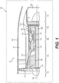
Fig. 1 is a schematic cross-sectional illustration of a gas turbine engine including an axial turbine having a turbine blade according to the various teachings of the present disclosure; -
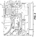
Fig. 2 is a detail cross-sectional illustration of a portion of the gas turbine engine ofFig. 1 , identified at 2 inFig. 1 , which includes the axial turbine having the turbine blade, and the turbine blade includes an exemplary cooling passage having an integral flow meter, with the cross-sectional illustration taken along a surface coincident with the camber line of the turbine airfoil at all radial spans; -
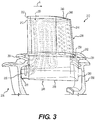
Fig. 3 is a side perspective view of the turbine blade ofFig. 2 , which includes a portion of a forward seal plate and a rear seal plate; -
Fig. 4 is a cross-sectional view of the turbine blade ofFig. 3 , taken along a surface intersecting the camber line of the turbine airfoil at all radial spans; -
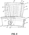
Fig. 5 is a front perspective view of the turbine blade ofFig. 2 , with the forward seal plate removed to illustrate the integral flow meter; -
Fig. 6 is a flow chart illustrating an exemplary method of manufacturing the turbine blade ofFig. 2 ; -
Fig. 7 is a schematic cross-sectional view of a turbine blade for an axial turbine that includes an exemplary cooling passage having the integral flow meter according to the various teachings of the present disclosure, with the cross-sectional illustration taken along a surface coincident with the camber line of the turbine airfoil at all radial spans; -
Fig. 8 is a schematic cross-sectional view of a turbine blade for an axial turbine that includes an exemplary cooling passage having an integral flow meter according to the various teachings of the present disclosure with the cross-sectional illustration taken along a surface coincident with the camber line of the turbine airfoil at all radial spans; and -
Fig. 9 is a flow chart illustrating an exemplary method of manufacturing the turbine blade ofFig. 8 . - The following detailed description is merely exemplary in nature and is not intended to limit the application and uses. Furthermore, there is no intention to be bound by any expressed or implied theory presented in the preceding technical field, background, brief summary or the following detailed description. In addition, those skilled in the art will appreciate that embodiments of the present disclosure may be practiced in conjunction with any type of turbine blade that would benefit from an internal flow meter, and that the axial turbine blade described herein for use with a gas turbine engine is merely one exemplary embodiment according to the present disclosure. Moreover, while the turbine blade is described herein as being used with an axial turbine of a gas turbine engine onboard a mobile platform or vehicle, such as a bus, motorcycle, train, motor vehicle, marine vessel, aircraft, rotorcraft and the like, the various teachings of the present disclosure can be used with a gas turbine engine or with an axial turbine associated with a stationary platform. Further, it should be noted that many alternative or additional functional relationships or physical connections may be present in an embodiment of the present disclosure. In addition, while the figures shown herein depict an example with certain arrangements of elements, additional intervening elements, devices, features, or components may be present in an actual embodiment. It should also be understood that the drawings are merely illustrative and may not be drawn to scale.
- With reference to
Fig. 1 , a partial, cross-sectional view of an exemplarygas turbine engine 100 is shown with the remaining portion of thegas turbine engine 100 being axi-symmetric about alongitudinal axis 140, which also comprises an axis of rotation for thegas turbine engine 100. In the depicted embodiment, thegas turbine engine 100 is an annular multi-spool turbofan gasturbine jet engine 100 within an aircraft 99, although other arrangements and uses may be provided. Thegas turbine engine 100 may be, for example, an auxiliary power unit ("APU"). As will be discussed herein, one or more axial turbine blades of thegas turbine engine 100 includes an integral flow meter, which supplies cooling fluid to a portion of the axial turbine blade. By using an integral flow meter, an external part is not required to meter cooling fluid to the turbine blade, thereby reducing cost and complexity associated with cooling the axial turbine blade. As used herein, the term "integral" denotes a component, such as the flow meter, which is formed within the turbine blade or defined within the turbine blade so as to be a part of the turbine blade and is not separate from the turbine blade itself. Stated another way, the term "integrally formed" and "integral" mean one-piece and excludes brazing, fasteners, or the like for coupling components in a fixed relationship as a single unit. - In this example, the
gas turbine engine 100 includesfan section 102, acompressor section 104, acombustor section 106, aturbine section 108, and anexhaust section 110. Thefan section 102 includes afan 112 mounted on arotor 114 that draws air into thegas turbine engine 100 and accelerates it. A fraction of the accelerated air exhausted from thefan 112 is directed through an outer (or first)bypass duct 116 and the remaining fraction of air exhausted from thefan 112 is directed into thecompressor section 104. Theouter bypass duct 116 is generally defined by aninner casing 118 and anouter casing 144. In the embodiment ofFig. 1 , thecompressor section 104 includes anintermediate pressure compressor 120 and ahigh pressure compressor 122. However, in other embodiments, the number of compressors in thecompressor section 104 may vary. In the depicted embodiment, theintermediate pressure compressor 120 and thehigh pressure compressor 122 sequentially raise the pressure of the air and direct a majority of the high pressure air into thecombustor section 106. A fraction of the compressed air bypasses thecombustor section 106 and is used to cool, among other components, turbine blades in theturbine section 108 via an inner bypass duct. - In the embodiment of
Fig. 1 , in thecombustor section 106, which includes acombustion chamber 124, the high pressure air is mixed with fuel and combusted. The high-temperature combusted air is then directed into theturbine section 108. In this example, theturbine section 108 includes three turbines disposed in axial flow series, namely, ahigh pressure turbine 126, anintermediate pressure turbine 128, and alow pressure turbine 130. However, it will be appreciated that the number of turbines, and/or the configurations thereof, may vary. In this embodiment, the high-temperature combusted air from thecombustor section 106 expands through and rotates eachturbine turbines gas turbine engine 100 via concentrically disposed shafts or spools. In one example, thehigh pressure turbine 126 drives thehigh pressure compressor 122 via ahigh pressure shaft 134, theintermediate pressure turbine 128 drives theintermediate pressure compressor 120 via anintermediate pressure shaft 136, and thelow pressure turbine 130 drives thefan 112 via alow pressure shaft 138. - With reference to
Fig. 2 , a portion of thehigh pressure turbine 126 of thegas turbine engine 100 ofFig. 1 is shown in greater detail. In this example, thehigh pressure turbine 126 is an axial turbine. It should be understood that while thehigh pressure turbine 126 is described herein as comprising a dual alloy axial turbine, thehigh pressure turbine 126 may comprise a single alloy, which may be cast or machined, or it may be an inserted blade and disk arrangement. In addition, while thehigh pressure turbine 126 is illustrated herein as being used with thegas turbine engine 100, which can be included with an auxiliary power unit, thehigh pressure turbine 126 can be employed with various types of engines, including, but not limited to, turbofan, turboprop, turboshaft, and turbojet engines, whether deployed onboard an aircraft, watercraft, or ground vehicle (e.g., a tank), included within industrial power generators, or utilized within another platform or application. - The
turbine section 108 includes aturbine duct section 200, which is in fluid communication with thecombustor section 106 to receive combustive gases from thecombustion chamber 124. A secondturbine duct section 202 is positioned downstream from thehigh pressure turbine 126, and is in fluid communication with the intermediate pressure turbine 128 (Fig. 1 ). The secondturbine duct section 202 directs thecombustive gas flow 204 from thehigh pressure turbine 126 to theintermediate pressure turbine 128. - The
combustive gas flow 204 drives rotation of thehigh pressure turbine 126, which drives thehigh pressure compressor 122. In this example, a first,forward seal plate 206 is coupled to thehigh pressure turbine 126 so as to be upstream from thehigh pressure turbine 126 in a direction of airflow, and a second,rear seal plate 208 is coupled to thehigh pressure turbine 126 so as to be downstream from thehigh pressure turbine 126 in the direction of air flow. Generally, theforward seal plate 206 at least partially defines a coolingfluid plenum 210. In this example, the coolingfluid plenum 210 receives cooling fluid or air from a source upstream from thehigh pressure turbine 126 and cooperates with theforward seal plate 206 to direct the cooling fluid into each of a plurality ofblades 212 of thehigh pressure turbine 126. Thus, in this embodiment, each of the plurality ofblades 212 comprise forward-fed turbine blades. - In one example, the cooling
fluid plenum 210 is in fluid communication with anoutlet 214, which provides cooling fluid, as indicated inFig. 2 byarrows 216, bled from a section of thegas turbine engine 100 upstream of thecombustor section 106. In this example, a portion of the airflow flowing within compressor section 104 (Fig. 1 ) is diverted into theinner bypass duct 118 to provide the coolingfluid 216. The coolingfluid 216 flowing from theinner bypass duct 118 is directed radially inward toward the engine centerline via theoutlet 214 and aninlet 218 defined through a portion of theforward seal plate 206. From theinlet 218, the cooling fluid 216 flows axially along thehigh pressure shaft 134 and ultimately flows into aninlet 220 of each of the plurality ofblades 212. Theinlet 220 provides each of the plurality ofblades 212 with cooling fluid to internally cool the plurality ofblades 212. - With continued reference to
Fig. 2 , thehigh pressure turbine 126 includes aturbine rotor 224 having a hub 226 and the plurality ofblades 212. The hub 226 is substantially annular about the axis of rotation orlongitudinal axis 140, and is coupled to thehigh pressure shaft 134. In one example, the hub 226 is substantially one-piece or monolithic. In one example, the hub 226 is composed of a nickel-based superalloy, having a relatively high Low Cycle Fatigue (LCF) resistance and moderate thermal tolerance. The hub 226 defines athroughbore 230 and an outerperipheral surface 232. Thethroughbore 230 is generally defined near the axial centerline of theturbine rotor 224, and enables theturbine rotor 224 to be positioned about at least the intermediate pressure shaft 136 (Fig. 1 ). The outerperipheral surface 232 is coupled to the plurality ofblades 212. - As will be discussed further herein, each of the plurality of
blades 212 is coupled to the outerperipheral surface 232 of the hub 226 so as to be spaced apart about a circumference of the hub 226. As each of the plurality ofblades 212 are substantially the same or similar, for ease of description, asingle blade 212 will be discussed in detail herein. With reference toFig. 3 , theblade 212 has anairfoil 238 extending outwardly from aroot 240. Theairfoil 238 includes aleading edge 242, a trailingedge 244, a first orpressure side 246 and a second orsuction side 248. At least onecooling passage 250 is defined internally within theblade 212 and is in fluid communication with theinlet 220 to receive the coolingfluid 216. Thecooling passage 250 extends from theroot 240 to a tip ortip portion 262 of theairfoil 238 to direct cooling fluid through theblade 212. As will be discussed further herein, at least one flow meter is formed or defined within theblade 212 at theinlet 220 to supply the cooling fluid 216 to the at least onecooling passage 250. - A first or
top surface 252 of theroot 240 is coupled to abottom surface 254 of theairfoil 238. A second orbottom surface 256 of theroot 240 is in contact with the outerperipheral surface 232 of the hub 226 to couple theblade 212 to the hub 226. For example, with reference toFig. 2 , theroot 240 may be metallurgically bonded to the outerperipheral surface 232 of the hub 226 via diffusion bonding along a bond line BL. It should be understood that various other techniques may be employed to couple theblade 212 to the hub 226, such as through blade attachment slots that receive thebottom surface 256 of theroot 240. - The
root 240 also includes a first orforward side 258 and a second oraft side 260. Each of thefirst side 258 and thesecond side 260 defineannular flanges 261, which extend outwardly from thefirst side 258 and thesecond side 260 to project over theforward seal plate 206 and therear seal plate 208. Thefirst side 258 is coupled to theforward seal plate 206, and is upstream from thesecond side 260 in a direction of airflow A. Thefirst side 258 defines theinlet 220 for thecooling passage 250. Generally, thecooling passage 250 of theblade 212 includes only a single inlet, theinlet 220. Thesecond side 260 is coupled to therear seal plate 208. - The
leading edge 242 of theairfoil 238 extends from thetip portion 262 to thebottom surface 254. The trailingedge 244 comprises the distalmost portion of theairfoil 238. Thepressure side 246 is substantially opposite thesuction side 248. Each of thepressure side 246 and thesuction side 248 extend along theairfoil 238 from theleading edge 242 to the trailingedge 244. - The
cooling passage 250 is defined within theroot 240 and theairfoil 238 to direct cooling fluid through theblade 212. Generally, thecooling passage 250 is defined wholly or entirely within theblade 212. With reference toFig. 4 , thecooling passage 250 is shown in greater detail. In this example, thecooling passage 250 includes theinlet 220, a first, leadingcooling passage 270, a second,secondary cooling passage 272, a third,tip plenum 274 and at least one fourth, trailingcooling passage 276. Each of the cooling passages 270-276 receive the cooling fluid 216 from theinlet 220 and cooperate to cool theblade 212. It should be noted that although while not illustrated herein for clarity, the airfoil 23 8 generally includes a plurality of film cooling holes over an exterior surface of theairfoil 238 to direct cooling fluid over the exterior surface of theairfoil 238. - The leading
cooling passage 270 is defined along thefirst side 258 of theroot 240 and adjacent to theleading edge 242 of theairfoil 238. The leadingcooling passage 270 has aninlet 278. Theinlet 278 is downstream from theinlet 220 and is in fluid communication with theinlet 220 to receive the coolingfluid 216. In certain embodiments, the leadingcooling passage 270 is also in fluid communication with a leadingedge cooling passage 280 via a plurality ofconduits 282. The leadingedge cooling passage 280 receives a portion of the cooling fluid 216 from the leadingcooling passage 270 via theconduits 282 to assist in further cooling theleading edge 242 of theairfoil 238. The leadingcooling passage 270 also includes aconduit 284 defined near thetip portion 262, which is in fluid communication with thetip plenum 274. Thus, theconduit 284 directs a portion of the cooling fluid 216 from the leadingcooling passage 270 to thetip plenum 274 to cool thetip portion 262 of theblade 212. - The
secondary cooling passage 272 is defined through theairfoil 238 and theroot 240 so as to be downstream from the leadingcooling passage 270, between the leadingcooling passage 270 and the trailingedge 244 of theblade 212. In this example, thesecondary cooling passage 272 comprises a serpentine passage. In other examples, thesecondary cooling passage 272 comprises a radial passage. Thesecondary cooling passage 272 is in fluid communication with anintegral flow meter 288 to receive the coolingfluid 216. In this regard, theflow meter 288 is defined through a portion of theairfoil 238 between the leadingcooling passage 270 and thesecondary cooling passage 272 to supply thesecondary cooling passage 272 with a predefined amount of the coolingfluid 216. In one example, theflow meter 288 comprises a bore defined through a dividingwall 289 of theairfoil 238 that has a predetermined diameter to direct a particular flow rate of the coolingfluid 216 into thesecondary cooling passage 272. The dividingwall 289 separates the leadingcooling passage 270 from thesecondary cooling passage 272, and is defined within theairfoil 238. In one embodiment, there may be two cooling passages and oneflow meter 288. In other embodiments there may be more than two cooling passages and more than oneflow meter 288. - While the
flow meter 288 is illustrated herein as having a diameter D2 that is substantially the same over a length L2 of theflow meter 288, theflow meter 288 can have a diameter that varies over the length L2 of theintegral flow meter 288. Moreover, while theflow meter 288 is illustrated herein as comprising a cylindrical bore (Fig. 5 ), theflow meter 288 can be formed with any desired shape, such as elliptical, triangular, etc. Further, with reference toFig. 2 , while theflow meter 288 is illustrated herein as being defined along an axis A2 substantially parallel to thelongitudinal axis 140 of the gas turbine engine, theflow meter 288 can be defined along an axis that is transverse to or oblique to thelongitudinal axis 140. The cross sectional flow area of the meter restricts the flow, and is sized based on the needs of the cooling circuit(s), in this example, thesecondary cooling passage 272. Generally, the area of theflow meter 288 is directly proportional to a flow rate of the cooling fluid 216 that is supplied to thesecondary cooling passage 272. In the example of a cylindrical bore for theflow meter 288, the cross-sectional area of theflow meter 288 is defined as:
- Wherein, D2 is the diameter of the
flow meter 288. With reference back toFig. 4 , theflow meter 288 includes aflow meter inlet 290 and aflow meter outlet 292. Theflow meter inlet 290 is in fluid communication with theinlet 220 to receive the coolingfluid 216, and theflow meter outlet 292 is in fluid communication with asecondary passage inlet 294 to provide thesecondary cooling passage 272 with the coolingfluid 216. Thus, in one embodiment, theflow meter 288 is the primary supply or source of cooling fluid 216 into thesecondary cooling passage 272. Stated another way, theflow meter 288 controls substantially a majority of the flow of the coolingfluid 216 into thesecondary cooling passage 272, as thesecondary cooling passage 272 is divided from the leadingcooling passage 270 by the dividingwall 289 and is not in direct fluid communication with the leadingcooling passage 270. Rather, thesecondary passage inlet 294 of thesecondary cooling passage 272 is primarily in fluid communication with theflow meter 288, and secondarily in fluid communication with the leadingcooling passage 270 at asecondary location 299. Generally, theflow meter 288 provides about 60% to about 100% of the flow of the coolingfluid 216 into thesecondary cooling passage 272, while thesecondary location 299 provides about 0% to about 40% of the flow of the coolingfluid 216 into thesecondary cooling passage 272. In one embodiment, theflow meter 288 controls all of the flow of the cooling fluid 216 at a first location between the leadingcooling passage 270 and thesecondary cooling passage 272, but the leadingcooling passage 270 and thesecondary cooling passage 272 may communicate at other locations, which are spaced apart from the first location. As will be discussed, theflow meter 288 can be machined to control an amount or flow rate of the coolingfluid 216 received into thesecondary cooling passage 272. - Although the flow rate through the
flow meter 288 is generally proportional to the cross-sectional area of theflow meter 288, the flow rate is also a function of aerodynamic flow characteristics within the metering hole that is theflow meter 288. Because these flow characteristics can be affected by the metering hole inlet and exit geometries, the flow rate through theflow meter 288 can also be affected by these geometries. The aerodynamic flow characteristics are generally quantified as the hole flow, or discharge, coefficient where the flow rate is directly proportional to the flow coefficient. Thus, flow rate can also be modified by changes to the shape of theflow meter inlet 290 or flowmeter outlet 292 of theflow meter 288, in addition to the area of the hole that is theflow meter 288. In this embodiment, the flow rate through the metering hole that is theflow meter 288 can be both increased and reduced depending upon the cooling requirements for thesecondary cooling passage 272. - For example, by making the inlet geometry of the
flow meter 288 near or at theflow meter inlet 290 the shape of a bellmouth in the cast form, one can ensure the flow coefficient is relatively high. However, if one were to remove the bellmouth shape that were cast and machine a smaller inlet fillet radius at theinlet 290 of theflow meter 288, the flow coefficient could be reduced. Similarly, by shaping theinlet 220 and/or the region adjacent to theinlet 220 as needed, the coolingfluid 216 would interact with the metering location or theflow meter 288 in a manner that would either increase or decrease, as intended, the flow coefficient. In this example, apassage 221 between theinlet 220 of theblade 212 and the metering location or flowmeter 288 is treated as a single inlet to theflow meter 288 for metering of the coolingfluid 216. Therefore, any modification to this geometry has the potential to increase or decrease the flow rate of theflow meter 288. For example, one or more disruptive features can be cast or machined within thepassage 221 to disrupt the flow of the coolingfluid 216 into theflow meter 288. These modifications can be modeled with fluid dynamics based computation modeling or empirically derived through testing. Thus, the geometry of theinlet 290 of theflow meter 288, the geometry of theinlet 220 and the geometry of thepassage 221 can each be modified, via machining or casting, in a predetermined manner to change a flow coefficient through theflow meter 288, and thereby increase or decrease a flow rate of the cooling fluid 216 that is the primary source of the coolingfluid 216 supplied to thesecondary cooling passage 272. In addition, theflow meter outlet 292 of theflow meter 288 can be machined to change the flow coefficient, and thus, the flow rate through theflow meter 288 as determined by the fluid dynamics based computation modeling or testing. - The
secondary cooling passage 272 also includes one or more trailingconduits 296 downstream from thesecondary passage inlet 294 and one ormore tip conduits 298. The trailingconduits 296 direct a portion of the cooling fluid 216 from thesecondary cooling passage 272 to the at least one trailingcooling passage 276. Thetip conduits 298 direct a portion of the cooling fluid 216 from thesecondary cooling passage 272 to thetip plenum 274. - The
tip plenum 274 is in fluid communication with theconduit 284 of the leadingcooling passage 270 and thetip conduits 298 of thesecondary cooling passage 272 to receive the portion of the coolingfluid 216. Thetip plenum 274 generally extends along thetip portion 262 from theleading edge 242 to the trailingedge 244 to cool thetip portion 262 of theairfoil 238. - At least one trailing
cooling passage 276 is in fluid communication with thesecondary cooling passage 272 via the trailingconduits 296. In this example, the at least one trailingcooling passage 276 comprises four trailingflow passages 276a-d, which are each in fluid communication with one or more of the trailingconduits 296 to receive the coolingfluid 216. Each of the trailingflow passages 276a-d receive the cooling fluid 216 from thesecondary cooling passage 272 to cool theairfoil 238 along the trailingedge 244. Thus, generally, the trailingflow passages 276a-d are defined within theairfoil 238 along the trailingedge 244 from thetip portion 262 to thebottom surface 254. - With reference to
Fig. 2 , theforward seal plate 206 defines theinlet 218 at adistal end 300 and is coupled to thefirst side 258 of theblade 212 at aproximal end 302. Thedistal end 300 can also define a first plurality of sealingteeth 304 and a second plurality of sealingteeth 306. The sealingteeth forward seal plate 206 and seal against adjacent structures within thegas turbine engine 100 to ensure that a substantial majority of the coolingfluid 216 is directed into theinlet 218. Theproximal end 302 defines a groove 308, which receives a sealingmember 310. The sealingmember 310 seats against thefirst side 258 and forms a seal that substantially prevents leakage of the cooling fluid 216 from the coolingfluid plenum 210. - The
rear seal plate 208 is coupled to thesecond side 260 of theblade 212 at aproximal end 312, and is coupled to an adjacent forward seal plate (not shown) at adistal end 314. Theproximal end 312 defines agroove 316, which receives asecond sealing member 318. Thesecond sealing member 318 seats against thesecond side 260 and forms a seal that substantially prevents leakage of a cooling fluid for an adjacent rotor (not shown). Thedistal end 314 defines a passage 320 for cooling fluid for the adjacent rotor, and can also define one ormore sealing fins 322 that extend outwardly from therear seal plate 208. The sealingfins 322 seal against adjacent structures within thegas turbine engine 100 to ensure that a substantial majority of the cooling fluid for the adjacent rotor is directed from the passage 320 into the corresponding inlet for the cooling passage of the adjacent rotor. Theforward seal plate 206 and therear seal plate 208 can be composed of any suitable material, such as a metal or metal alloy. - With reference to
Fig. 6 , and with continued reference toFigs. 1-5 , in accordance with one example, amethod 399 of manufacturing theblade 212 with theflow meter 288 is shown. The method begins at 400. At 402, theblade 212 is formed. In one example, theblade 212 is formed using investment casting. In this example, a core is formed from a ceramic material, which may be cast, molded, or manufactured from a ceramic using ceramic additive manufacturing or selective laser sintering. Generally, the core comprises the inverse of thecooling passage 250 shown inFig. 4 without theflow meter 288. Stated another way, the core comprises theinlet 220, the leadingcooling passage 270, thesecondary cooling passage 272, thetip plenum 274 and the at least one trailingcooling passage 276, but does not include theflow meter 288. With the core formed, the core is positioned within a die. With the core positioned within the die, the die is injected with liquid wax such that liquid wax surrounds the core. A wax sprue or conduit may also be coupled to the core within the die to aid in the formation of theblade 212. Once the wax has hardened to form a wax pattern, the wax pattern is coated or dipped in ceramic to create a ceramic mold about the wax pattern. After coating the wax pattern with ceramic, the wax pattern may be subject to stuccoing and hardening until the ceramic mold has reached the desired thickness. - With the ceramic mold at the desired thickness, the wax is heated to melt the wax out of the ceramic mold. With the wax melted out of the ceramic mold, voids remain surrounding the core. The ceramic mold is filled with molten metal or metal alloy. In one example, the molten metal is poured down an opening created by the wax sprue. Once the metal or metal alloy has solidified, the ceramic is removed from the metal or metal alloy, through chemical leaching, for example, leaving the
cooling passage 250 formed in the metal or metal alloy, as illustrated inFig. 4 . - It should be noted that alternatively the
blade 212 may be formed using conventional dies with one or more portions of the cooling passage 250 (or portions adjacent to the cooling passage 250) comprising a fugitive core insert. - With the
blade 212 formed, at 404, the cooling requirements for thesecondary cooling passage 272 are determined. In one example, the cooling requirements are pre-defined, via a fluid dynamics analysis performed using a computer model of theblade 212. In other embodiments, the cooling requirements are pre-defined based on experimental testing and simulation. In still other embodiments, the cooling requirements are defined based on a regulation from one or more governing agencies. - At 406, the
flow meter 288 is machined through theinlet 220 of theblade 212. In this regard, given the determined cooling requirements for thesecondary cooling passage 272, theflow meter 288 is defined through theinlet 220 to fluidly couple theinlet 220 to thesecondary cooling passage 272. In this example, with reference toFig. 4 , theinlet 220 has a diameter D3, which is sized to enable a tool to be inserted into theinlet 220 to form or define theflow meter 288. Generally, the diameter D3 of theinlet 220 is greater than the diameter D2 of theflow meter 288. In one example, theflow meter 288 is machined through the dividingwall 289 by drilling, grinding and/or milling the bore that defines theflow meter 288 through the dividingwall 289. In other embodiments, theflow meter 288 is formed by electrical discharge machining (EDM). With reference toFig. 6 , optionally at 407, one or more of the geometry of theflow meter inlet 290 of theflow meter 288, theflow meter outlet 292 of theflow meter 288, the geometry of theinlet 220 and the geometry of thepassage 221 are machined, via EDM for example, to change the flow coefficient through theflow meter 288, and thereby increase or decrease a flow rate of the cooling fluid 216 that is the primary source of the coolingfluid 216 supplied to thesecondary cooling passage 272. - With continued reference to
Fig. 6 , at 408, it is determined whether there is sufficient cooling flow into thesecondary cooling passage 272. In one example, this determination can be made by testing theblade 212 in a test rig, in which a cooling flow through theblade 212, including thesecondary cooling passage 272, is measured. In another example this determination may be made by dimensional inspection of theflow meter 288 and theinlet 220. - Based on the determination at 408, if the
secondary cooling passage 272 is receiving the desired amount of the cooling fluid 216 from theflow meter 288, at 410, the method ends. Otherwise, at 412, theflow meter 288 is further machined through theinlet 220, theinlet 220 is further machined and/or thepassage 221 is further machined to adjust the coolingfluid 216 supplied to thesecondary cooling passage 272. In one example, the diameter D2 of the bore of theflow meter 288 is enlarged to increase the flow rate of the cooling fluid 216 to thesecondary cooling passage 272; however, one or more of theinlet 290, theoutlet 292, theinlet 220 of theblade 212 and thepassage 221 can be modified to reduce the flow rate of the cooling fluid 216 to thesecondary cooling passage 272. The method proceeds back to 408. - The method of
Fig. 6 can be repeated to form any number ofblades 212 for use with theturbine rotor 224. With the desired number ofblades 212 formed, theblades 212 are consolidated into a ring, and coupled together through any conventional technique to form a blade ring. The blade ring comprising theblades 212 is coupled to the hub 226 to form theturbine rotor 224. With theturbine rotor 224 formed and assembled, theturbine rotor 224 can be installed in thegas turbine engine 100. - As each of the
blades 212 of theturbine rotor 224 include the cooling passage, having theintegral flow meter 288, the coolingfluid 216 is supplied to theblades 212 without requiring additional metering plates or metering components. By forming theflow meter 288 integrally with theblade 212 to provide the desired cooling flow, the amount of cooling fluid 216 used by theblade 212 substantially comports with the amount of cooling flow needed by theblade 212, thereby reducing instances where theblade 212 is receivingmore cooling fluid 216 than needed, which may impact fuel consumption of thegas turbine engine 100. Moreover, the integrally formedflow meter 288 ensures the proper amount of the coolingfluid 216 is supplied to thesecondary cooling passage 272 of theblade 212, thereby reducing the likelihood that theblade 212 is insufficiently cooled. - It should be noted that while the
flow meter 288 is described herein as being separately defined after the formation of theblade 212, it will be understood that the present disclosure is not so limited. In this regard, theflow meter 288 can be part of the core used with the investment casting of theblade 212 such that theflow meter 288 is integrally formed or defined during the investment casting of theblade 212. In this example, theflow meter 288 defined by the investment casting can be separately machined via drilling, grinding, milling and/or EDM to tune the amount of cooling fluid 216 received by thesecondary cooling passage 272 in a separate step after formation of theblade 212. - It should be noted that the
cooling passage 250 described with regard toFigs. 1-6 is merely exemplary, and depending upon the shape and size of the axial turbine, the shape of thecooling passage 250 may vary. For example, with reference toFig. 7 , a cross-section of ablade 500 of an axial turbine is shown. As theblade 500 includes components that are the same or substantially similar to theblade 212 discussed with regard toFigs. 1-6 , the same reference numerals will be used herein to denote the same or similar components. In this example, theblade 500 is metallurgically bonded to an outer peripheral surface of a hub via diffusion bonding along a bond line BL2, and does not include theroot 240 as discussed with regard toFigs. 1-6 . - The
blade 500 includes an airfoil 502 having aleading edge 504, the trailingedge 244, the first orpressure side 246 and the second orsuction side 248. In this example, due to the shape of theblade 500, aninlet 508 is defined through a portion of the airfoil 502 below theleading edge 504. Thus, in this example, the cooling fluid 216 flows axially along thehigh pressure shaft 134 and ultimately flows into theinlet 508 of each of the plurality ofblades 500 adjacent to or near theleading edge 504. Theinlet 508 provides each of the plurality ofblades 500 with cooling fluid to internally cool the plurality ofblades 500. At least onecooling passage 510 is defined internally within theblade 500 and is in fluid communication with theinlet 508. - The
cooling passage 510 is defined within the airfoil 502 to direct cooling fluid through theblade 212. Generally, thecooling passage 510 is defined wholly or entirely within the airfoil 502. Thecooling passage 510 includes theinlet 508, the leadingcooling passage 270, thesecondary cooling passage 272, thetip plenum 274 and the at least one trailingcooling passage 276. Each of the cooling passages 270-276 receive the cooling fluid 216 from theinlet 508 and cooperate to cool theblade 500. It should be noted that although while not illustrated herein for clarity, the airfoil 502 generally includes a plurality of film cooling holes over an exterior surface of the airfoil 502 to direct cooling fluid over the exterior surface of the airfoil 502. As thecooling passage 510, including theintegral flow meter 288, is substantially the same as thecooling passage 250 and theflow meter 288 discussed with reference toFigs. 1-6 with the exception of the location of theinlet 508, thecooling passage 510 will not be discussed in detail herein. Moreover, as theblade 500 with the integral flow meter can be formed using the method of blocks 400-412 ofFig. 6 , the method of manufacturing theblade 500 will also not be discussed in detail herein. - It should be noted that the present disclosure is not limited to forward fed
turbine blades Fig. 8 , a bottom fedturbine blade 600 is shown. Theblade 600 is coupled to a hub to form a turbine rotor (not shown), and can be used with thegas turbine engine 100 ofFigs. 1-6 . Theblade 600 has anairfoil 602 extending outwardly from aroot 604. Theairfoil 602 includes aleading edge 606, a trailingedge 608, a first orpressure side 610 and a second orsuction side 612. At least one or a plurality of coolingpassages 614 are defined internally within theblade 600, and each of the plurality of coolingpassages 614 are in fluid communication with respective ones of a plurality of integral flow meters 616. As will be discussed, the plurality of coolingpassages 614 extend from theroot 604 to a tip ortip portion 618 of theairfoil 602 to direct cooling fluid through theblade 600. - A first or
top surface 620 of theroot 604 is coupled to theairfoil 602. A second orbottom surface 622 of theroot 604 defines the plurality of flow meters 616, as will be discussed further herein. Theroot 604 also includes afirst side 624 opposite asecond side 626. Theleading edge 606 of theairfoil 602 extends from thetip portion 618 to thetop surface 620 of theroot 604. The trailingedge 608 comprises the distalmost portion of theairfoil 602. Thepressure side 610 is substantially opposite thesuction side 612. Each of thepressure side 610 and thesuction side 612 extend along theairfoil 602 from theleading edge 606 to the trailingedge 608. - The plurality of cooling
passages 614 are defined within theroot 604 and theairfoil 602 to direct cooling fluid through theblade 600. Generally, the plurality of coolingpassages 614 are defined wholly or entirely within theblade 600. In this example, the plurality of coolingpassages 614 include afirst cooling passage 614a, asecond cooling passage 614b, athird cooling passage 614c and afourth cooling passage 614d. It will be understood, however, that theblade 600 can include more or less cooling passages, if desired. Each of thecooling passages 614a-d receive the cooling fluid 216 from arespective inlet 619a-e, and each of the plurality offlow meters 616a-e are defined at therespective inlet 619a-e that supplies the cooling fluid 216 to the respective one of the plurality ofcooling passages 614a-d. It should be noted that although while not illustrated herein for clarity, theairfoil 602 generally may include a plurality of film cooling holes over an exterior surface of theairfoil 602 to direct cooling fluid over the exterior surface of theairfoil 602. - The
first cooling passage 614a is adjacent to theleading edge 606 and includes afirst branch 628 and asecond branch 629 that merge into amain branch 631. Thefirst branch 628 and thesecond branch 629 are defined in theroot 604, and merge into themain branch 631 adjacent to thetop surface 620 of theroot 604 such that themain branch 631 extends through theairfoil 602. Thefirst branch 628 and thesecond branch 629 each receive the cooling fluid 216 from a respective one of the plurality of flow meters 616, such asflow meter second cooling passage 614b, thethird cooling passage 614c and thefourth cooling passage 614d extend from theroot 604 to thetip portion 618 of theairfoil 602, and are each in fluid communication with a respective one of the plurality of flow meters 616, for example, flowmeter 616c,flow meter 616d and flowmeter 616e, respectively. - Each of the plurality of
flow meters 616a-e is formed within or defined in thebottom surface 622 of theroot 604 about a respective one of theinlets 619a-e to supply each of the plurality ofcooling passages 614a-d with a predefined amount of the coolingfluid 216. In one example, each of the plurality offlow meters 616a-e comprise a volume of additional material M defined about therespective inlet 619a-e that is able to be machined to a predetermined diameter to direct a particular flow rate of the coolingfluid 216 into the respective one of the plurality ofcooling passages 614a-d. The additional material M may cover about 10% to about 100% of the area of theinlet 619a-e prior to machining the additional material M at therespective inlet 619a-e to achieve the final configuration for therespective inlet 619a-e that corresponds to the predetermined flow requirement for theparticular cooling passage 614a-d. While each of the plurality offlow meters 616a-e are illustrated herein as having a thickness D6 (i.e. (D5-D4)/2) that is substantially the same over a height h4 of theflow meters 616a-e, the plurality offlow meters 616a-e can have a diameter that varies over the height h4 of the plurality offlow meters 616a-e. Generally, each of the plurality offlow meters 616a-e are defined with the diameter D6, which can be machined in various amounts to create therespective inlet 619a-e with a diameter as needed for the selected amount of the coolingfluid 216. Stated another way, each of the plurality offlow meters 616a-e can be initially defined as the additional material M that surrounds therespective inlets 619a-e with the diameter D4, and the additional material M surrounding each of theinlets 619a-e can be machined up to a diameter D5 as needed to provide a predetermined amount of the cooling fluid 216 to the respective one of the plurality ofcooling passages 614a-d. - Moreover, while the plurality of
flow meters 616a-e are illustrated herein as being machinable into a cylindrical bore, the plurality offlow meters 616a-e can be formed with any desired shape, such as elliptical, triangular, etc. Further, while the plurality offlow meters 616a-e are illustrated herein as being defined along an axis A4 substantially perpendicular to thelongitudinal axis 140 of the gas turbine engine, the additional material M of the plurality offlow meters 616a-e can be defined along an axis that is transverse to or oblique to thelongitudinal axis 140. In addition, while each of the plurality offlow meters 616a-e are illustrated as having substantially the same size and shape (i.e. the same diameter D6 and the same height h4), one or more of the plurality offlow meters 616a-e can have a different shape, diameter and/or height. Generally, the cross-sectional area of each of theinlets 619a-e is directly proportional to the flow rate of the cooling fluid 216 that is supplied to the respective ones of the plurality ofcooling passages 614a-d. In the example of a cylindrical bore for each of the plurality offlow meters 616a-e, the cross-sectional flow area of a single one of the inlets is defined as:
- Each of the plurality of
flow meters 616a-e includes aflow meter inlet 630a-e and aflow meter outlet 632a-e. The respectiveflow meter inlet 630a-e is in fluid communication with the cooling fluid 216 at therespective inlet 619a-e, and the respectiveflow meter outlet 632a-e is in fluid communication with the respective one of the plurality ofcooling passages 614a-d. The respective one or more of the plurality offlow meters 616a-e cooperate with therespective inlet 619a-e to control all of the flow of the coolingfluid 216 into the respective one of the plurality ofcooling passages 614a-d. As will be discussed, the additional material M can be machined to control an amount or flow rate of the coolingfluid 216 received into the respective one of the plurality ofcooling passages 614a-d at therespective inlet 619a-e. In one example, the flow rate may be reduced in theflow meters 616a-e by modifying theinlet 619a-e at thebottom surface 622. In this regard, one or more fillets, bumps or contours may be defined on thebottom surface 622 adjacent to, near or around one or more of theinlets 619a-e to alter the flow through therespective flow meters 616a-e. - With reference to
Fig. 9 , and with continued reference toFig. 8 , in accordance with one example, amethod 799 of manufacturing theblade 600 with the plurality offlow meters 616a-e is shown. The method begins at 800. At 802, theblade 600 is formed. In one example, theblade 600 is formed using investment casting, as discussed with regard toFig. 6 , above. As the remainder of the investment casting process for theblade 600 is substantially similar to the process discussed with regard toFig. 6 , the method of investment casting theblade 600 will not be discussed in great detail herein. Briefly, however, the core that is formed in investment casting theblade 600 comprises the inverse of the plurality ofcooling passages 614a-d, including the extra material M of the plurality offlow meters 616a-e that surrounds each of theinlets 619a-e. With the core positioned within the die, the die is injected with liquid wax such that liquid wax surrounds the core. Once the wax has hardened to form a wax pattern, the wax pattern is coated or dipped in ceramic to create the ceramic mold about the wax pattern. With the ceramic mold at the desired thickness, the wax is heated to melt the wax out of the ceramic mold. The ceramic mold is filled with molten metal or metal alloy. Once the metal or metal alloy has solidified, the ceramic is removed from the metal or metal alloy, through chemical leaching, for example, leaving the plurality ofcooling passages 614a-d, including the extra material M surrounding each of theinlets 619a-e of the plurality ofcooling passages 614a-d formed in the metal or metal alloy. - It should be noted that alternatively the
blade 600 may be formed using conventional dies with one or more portions of the plurality ofcooling passages 614a-d, including the extra material M surrounding each of theinlets 619a-e (or portions adjacent to the plurality ofcooling passages 614a-d) comprising a fugitive core insert. - With the
blade 600 formed, at 804, the cooling requirements for each of the plurality ofcooling passages 614a-d are determined. In one example, the cooling requirements are pre-defined, via a fluid dynamics analysis performed using a computer model of theblade 600. In other embodiments, the cooling requirements are pre-defined based on experimental testing and simulation. In still other embodiments, the cooling requirements are defined based on a regulation from one or more governing agencies. - At 806, based on the determination at 804, the additional material M of one or more of the plurality of
flow meters 616a-e is machined to adjust the amount or flow rate of the coolingfluid 216 received by the particular one of the plurality ofcooling passages 614a-d at therespective inlet 619a-e. In this regard, given the determined cooling requirements for each of the plurality ofcooling passages 614a-d, the additional material M is removed, if necessary, to provide for a greater flow rate of the cooling fluid 216 to enter the respective one of the plurality ofcooling passages 614a-d at therespective inlet 619a-e. In one example, the additional material M of the plurality offlow meters 616a-e is machined by drilling, grinding and/or milling about the respective one of theinlets 619a-e. In other embodiments, the additional material M is removed by electrical discharge machining (EDM). - With continued reference to
Fig. 9 , at 808, it is determined whether there is sufficient cooling flow into each of the plurality ofcooling passages 614a-d. In one example, this determination can be made by testing theblade 600 in a test rig, in which a cooling flow through theblade 600, including the plurality ofcooling passages 614a-d, is measured. It may also be determined through dimensional inspection. - Based on the determination at 808, if each of the plurality of
cooling passages 614a-d are receiving the desired amount of the cooling fluid 216 from the respective ones of theinlets 619a-e, at 810, the method ends. Otherwise, at 812, the additional material M of respective ones of the plurality offlow meters 616a-e is further removed by machining to increase the cooling fluid 216 flow rate supplied to the respective ones of the plurality ofcooling passages 614a-d. The method proceeds back to 808. - The method of
Fig. 9 can be repeated to form any number ofblades 600 for use with a turbine rotor of thegas turbine engine 100. With the desired number ofblades 600 formed, theblades 600 are consolidated into a ring, and coupled together to form a blade ring, which is coupled to the hub of the turbine rotor as discussed above with regard to theblades 212. With the turbine rotor formed and assembled, the turbine rotor can be installed in thegas turbine engine 100. - As each of the
blades 600 include the plurality ofcooling passages 614a-d, each having one or more of the plurality ofintegral flow meters 616a-e, the coolingfluid 216 is supplied to theblades 600 without requiring additional metering plates or metering components. By forming the plurality offlow meters 616a-e integrally with theblade 600 with the additional material M, one or more of the plurality offlow meters 616a-e can be machined to remove portions of the additional material M to adjust the coolingfluid 216 individually for each of the plurality ofcooling passages 614a-d. This adjustability reduces instances where one or more of the plurality ofcooling passages 614a-d is receivingmore cooling fluid 216 than needed, which may impact fuel consumption of thegas turbine engine 100. Moreover, the plurality offlow meters 616a-e having the additional material M which is removable ensures the proper amount of the coolingfluid 216 is supplied to each of the plurality ofcooling passages 614a-d of theblade 600, thereby reducing the likelihood that theblade 600 is insufficiently cooled. - While at least one exemplary embodiment has been presented in the foregoing detailed description, it should be appreciated that a vast number of variations exist. It should also be appreciated that the exemplary embodiment or exemplary embodiments are only examples, and are not intended to limit the scope, applicability, or configuration of the disclosure in any way. Rather, the foregoing detailed description will provide those skilled in the art with a convenient road map for implementing the exemplary embodiment or exemplary embodiments. It should be understood that various changes can be made in the function and arrangement of elements without departing from the scope of the disclosure as set forth in the appended claims.
Claims (4)
- A turbine blade (212, 500), comprising:an airfoil (238, 502) extending outwardly from a root (240), the airfoil having a trailing edge (244) and a leading edge (242, 504) opposite the trailing edge, the root having a forward side (258) and an aft side (260);at least one cooling passage (250, 510) defined internally within the turbine blade (212, 500), the at least one cooling passage being in fluid communication with a source of cooling fluid via an inlet (220, 508), the inlet (220, 508) being configured to receive a cooling fluid (216), the inlet being defined in the forward side (258) of the root (240),wherein the at least one cooling passage (250, 510) comprises at leasta first cooling passage (270) along the leading edge (242, 504),at least one trailing cooling passage (276), anda second cooling passage (272) between the first cooling passage (270) and the at least one trailing cooling passage (276), wherein the second cooling passage (272) is a serpentine cooling passage,wherein the first cooling passage is separated from the second cooling passage by a dividing wall (289) defined within the airfoil, the dividing wall (289) separating the first cooling passage (270) from the second cooling passage (272) such that the first cooling passage (270) is not in direct fluid communication with the second cooling passage (272),wherein the second cooling passage includes a secondary passage inlet (294) that is configured to receive the cooling fluid (216) and the second cooling passage is in fluid communication with one or more trailing conduits (296) downstream from the secondary passage inlet (294) and configured to direct the cooling fluid into the at least one trailing cooling passage;the turbine blade further comprisingat least one flow meter (288) defined through the dividing wall (289) of the turbine blade at the inlet (220, 508), the at least one flow meter having a flow meter inlet (290) in fluid communication with the inlet (220, 508) and a flow meter outlet (292) in fluid communication with the secondary passage inlet (294) that is configured to supply the cooling fluid to the second cooling passage, wherein the at least one flow meter is a bore defined through the dividing wall (289) that is configured to supply about 60% to about 100% of the cooling fluid to the second cooling passage; andwherein the second cooling passage (272) is in fluid communication with the first cooling passage at a secondary location (299), the secondary location (299) defined through the dividing wall and configured to supply about 0% to about 40% of the cooling fluid to the second cooling passage.
- The turbine blade (212, 500) of Claim 1, wherein the inlet (220, 508) has a first diameter, the at least one flow meter (288) has a second diameter, and the first diameter is greater than the second diameter.
- A method of manufacturing a turbine blade (600), of one of claims 1 and 2, comprising:forming the turbine blade (600) with an airfoil (602), a root (604) and a plurality of integral cooling passages (614), each of the plurality of cooling passages (614) having at least a respective inlet (619) in fluid communication with a source of a cooling fluid, each inlet (619) of the plurality of cooling passages defined at a bottom surface (622) of a root (604), each of the plurality of cooling passages extending to a tip portion (618) of the airfoil (602), each of the plurality of cooling passages associated with a respective flow meter (616), and the respective flow meter comprises additional material (M) defined about the respective inlet (619); andmachining the additional material of the respective flow meter at the inlet of at least one of the plurality of cooling passages to remove portions of the additional material to adjust the flow of the cooling fluid to the respective at least one of the plurality of cooling passages based on a determined cooling requirement for the respective at least one of the plurality of cooling passages.
- The method of Claim 3, wherein machining the additional material (M) of the respective flow meter (616) further comprises:
removing further portions of the additional material about the inlet (619) of the at least one of the plurality of cooling passages (614) to adjust the flow of the cooling fluid.
Applications Claiming Priority (1)
| Application Number | Priority Date | Filing Date | Title |
|---|---|---|---|
| US15/285,347 US10683763B2 (en) | 2016-10-04 | 2016-10-04 | Turbine blade with integral flow meter |
Publications (2)
| Publication Number | Publication Date |
|---|---|
| EP3306036A1 EP3306036A1 (en) | 2018-04-11 |
| EP3306036B1 true EP3306036B1 (en) | 2021-02-17 |
Family
ID=60019762
Family Applications (1)
| Application Number | Title | Priority Date | Filing Date |
|---|---|---|---|
| EP17194625.4A Active EP3306036B1 (en) | 2016-10-04 | 2017-10-03 | Turbine blade with a cooling passage and a flow meter |
Country Status (2)
| Country | Link |
|---|---|
| US (2) | US10683763B2 (en) |
| EP (1) | EP3306036B1 (en) |
Families Citing this family (9)
| Publication number | Priority date | Publication date | Assignee | Title |
|---|---|---|---|---|
| JP5905631B1 (en) * | 2015-09-15 | 2016-04-20 | 三菱日立パワーシステムズ株式会社 | Rotor blade, gas turbine provided with the same, and method of manufacturing rotor blade |
| US10641106B2 (en) * | 2017-11-13 | 2020-05-05 | Honeywell International Inc. | Gas turbine engines with improved airfoil dust removal |
| US11021961B2 (en) | 2018-12-05 | 2021-06-01 | General Electric Company | Rotor assembly thermal attenuation structure and system |
| US10767492B2 (en) | 2018-12-18 | 2020-09-08 | General Electric Company | Turbine engine airfoil |
| US10711620B1 (en) * | 2019-01-14 | 2020-07-14 | General Electric Company | Insert system for an airfoil and method of installing same |
| KR102162970B1 (en) * | 2019-02-21 | 2020-10-07 | 두산중공업 주식회사 | Airfoil for turbine, turbine including the same |
| KR102161765B1 (en) * | 2019-02-22 | 2020-10-05 | 두산중공업 주식회사 | Airfoil for turbine, turbine including the same |
| US11629601B2 (en) * | 2020-03-31 | 2023-04-18 | General Electric Company | Turbomachine rotor blade with a cooling circuit having an offset rib |
| EP4134515A1 (en) | 2021-08-12 | 2023-02-15 | Rolls-Royce plc | Blade for use in a gas turbine engine and gas turbine engine for an aircraft |
Family Cites Families (32)
| Publication number | Priority date | Publication date | Assignee | Title |
|---|---|---|---|---|
| US5403159A (en) * | 1992-11-30 | 1995-04-04 | United Technoligies Corporation | Coolable airfoil structure |
| US5403156A (en) | 1993-10-26 | 1995-04-04 | United Technologies Corporation | Integral meter plate for turbine blade and method |
| US5387085A (en) | 1994-01-07 | 1995-02-07 | General Electric Company | Turbine blade composite cooling circuit |
| JP2851575B2 (en) * | 1996-01-29 | 1999-01-27 | 三菱重工業株式会社 | Steam cooling wings |
| US6139269A (en) * | 1997-12-17 | 2000-10-31 | United Technologies Corporation | Turbine blade with multi-pass cooling and cooling air addition |
| DE19801804C2 (en) | 1998-01-19 | 1999-10-28 | Siemens Ag | Turbine blade and method for inspecting and / or cleaning a turbine blade |
| JPH11241602A (en) * | 1998-02-26 | 1999-09-07 | Toshiba Corp | Gas turbine blade |
| US6092991A (en) | 1998-03-05 | 2000-07-25 | Mitsubishi Heavy Industries, Ltd. | Gas turbine blade |
| US6186741B1 (en) | 1999-07-22 | 2001-02-13 | General Electric Company | Airfoil component having internal cooling and method of cooling |
| JP3361501B2 (en) * | 2000-03-02 | 2003-01-07 | 株式会社日立製作所 | Closed-circuit blade cooling turbine |
| US6491496B2 (en) | 2001-02-23 | 2002-12-10 | General Electric Company | Turbine airfoil with metering plates for refresher holes |
| EP1507957B1 (en) * | 2002-05-22 | 2005-08-24 | ALSTOM Technology Ltd | Coolable component and method for the production of a through-opening in a coolable component |
| US7014424B2 (en) | 2003-04-08 | 2006-03-21 | United Technologies Corporation | Turbine element |
| DE102004002327A1 (en) * | 2004-01-16 | 2005-08-04 | Alstom Technology Ltd | Cooled shovel for a gas turbine |
| DE502004004290D1 (en) | 2004-05-21 | 2007-08-23 | Siemens Ag | Steam turbine component and method of cooling a steam turbine and use |
| US7097419B2 (en) * | 2004-07-26 | 2006-08-29 | General Electric Company | Common tip chamber blade |
| GB0418914D0 (en) | 2004-08-25 | 2004-09-29 | Rolls Royce Plc | Turbine component |
| EP1717416A1 (en) | 2005-04-25 | 2006-11-02 | Siemens Aktiengesellschaft | Turbine blade, use of the blade and manufacturing method thereof |
| US7413406B2 (en) | 2006-02-15 | 2008-08-19 | United Technologies Corporation | Turbine blade with radial cooling channels |
| US7568887B1 (en) | 2006-11-16 | 2009-08-04 | Florida Turbine Technologies, Inc. | Turbine blade with near wall spiral flow serpentine cooling circuit |
| US7780414B1 (en) | 2007-01-17 | 2010-08-24 | Florida Turbine Technologies, Inc. | Turbine blade with multiple metering trailing edge cooling holes |
| US7967563B1 (en) | 2007-11-19 | 2011-06-28 | Florida Turbine Technologies, Inc. | Turbine blade with tip section cooling channel |
| US8016547B2 (en) * | 2008-01-22 | 2011-09-13 | United Technologies Corporation | Radial inner diameter metering plate |
| US8043059B1 (en) | 2008-09-12 | 2011-10-25 | Florida Turbine Technologies, Inc. | Turbine blade with multi-vortex tip cooling and sealing |
| US8083486B1 (en) | 2009-05-15 | 2011-12-27 | Florida Turbine Technologies, Inc. | Turbine blade with cooling flow modulation |
| US8337158B1 (en) | 2009-10-22 | 2012-12-25 | Florida Turbine Technologies, Inc. | Turbine blade with tip cap |
| US8807943B1 (en) | 2010-02-15 | 2014-08-19 | Florida Turbine Technologies, Inc. | Turbine blade with trailing edge cooling circuit |
| US8827647B1 (en) * | 2010-06-24 | 2014-09-09 | Florida Turbine Technologies, Inc. | Turbine blade with root section cooling |
| KR101552450B1 (en) * | 2011-03-11 | 2015-09-11 | 미츠비시 히타치 파워 시스템즈 가부시키가이샤 | Gas turbine rotor blade, and gas turbine |
| US20140161625A1 (en) | 2012-12-11 | 2014-06-12 | General Electric Company | Turbine component having cooling passages with varying diameter |
| US9777575B2 (en) | 2014-01-20 | 2017-10-03 | Honeywell International Inc. | Turbine rotor assemblies with improved slot cavities |
| GB201506728D0 (en) * | 2015-04-21 | 2015-06-03 | Rolls Royce Plc | Thermal shielding in a gas turbine |
-
2016
- 2016-10-04 US US15/285,347 patent/US10683763B2/en active Active
-
2017
- 2017-10-03 EP EP17194625.4A patent/EP3306036B1/en active Active
-
2020
- 2020-04-22 US US16/855,591 patent/US20200291792A1/en not_active Abandoned
Non-Patent Citations (1)
| Title |
|---|
| None * |
Also Published As
| Publication number | Publication date |
|---|---|
| US10683763B2 (en) | 2020-06-16 |
| US20200291792A1 (en) | 2020-09-17 |
| US20180094527A1 (en) | 2018-04-05 |
| EP3306036A1 (en) | 2018-04-11 |
Similar Documents
| Publication | Publication Date | Title |
|---|---|---|
| EP3306036B1 (en) | Turbine blade with a cooling passage and a flow meter | |
| EP3216981B1 (en) | Radial turbine blade comprising a diverging-converging cooling passage | |
| EP2867472B1 (en) | Turbine vane | |
| US11035236B2 (en) | Baffle for a component of a gas turbine engine | |
| EP3495617B1 (en) | Airfoil with internal cooling passages | |
| US11448093B2 (en) | Turbine vane with dust tolerant cooling system | |
| US11230929B2 (en) | Turbine component with dust tolerant cooling system | |
| US20170081967A1 (en) | Casting of thin wall hollow airfoil sections | |
| CN108339941B (en) | Investment casting core, method of casting airfoil, and turbine blade assembly | |
| CN112343665B (en) | Engine component with cooling holes | |
| EP2998511B1 (en) | Cooling passage with surface features | |
| US20180223672A1 (en) | Investment casting core | |
| US20210207493A1 (en) | Engine component with cooling hole | |
| EP3495615B1 (en) | Airfoil with internal cooling passages | |
| EP3495618B1 (en) | Airfoil with internal cooling passages | |
| EP3495616B1 (en) | Airfoil with internal cooling passages | |
| EP3495619B1 (en) | Airfoil with internal cooling passages |
Legal Events
| Date | Code | Title | Description |
|---|---|---|---|
| PUAI | Public reference made under article 153(3) epc to a published international application that has entered the european phase |
Free format text: ORIGINAL CODE: 0009012 |
|
| STAA | Information on the status of an ep patent application or granted ep patent |
Free format text: STATUS: REQUEST FOR EXAMINATION WAS MADE |
|
| 17P | Request for examination filed |
Effective date: 20171003 |
|
| AK | Designated contracting states |
Kind code of ref document: A1 Designated state(s): AL AT BE BG CH CY CZ DE DK EE ES FI FR GB GR HR HU IE IS IT LI LT LU LV MC MK MT NL NO PL PT RO RS SE SI SK SM TR |
|
| AX | Request for extension of the european patent |
Extension state: BA ME |
|
| STAA | Information on the status of an ep patent application or granted ep patent |
Free format text: STATUS: EXAMINATION IS IN PROGRESS |
|
| 17Q | First examination report despatched |
Effective date: 20190128 |
|
| GRAP | Despatch of communication of intention to grant a patent |
Free format text: ORIGINAL CODE: EPIDOSNIGR1 |
|
| STAA | Information on the status of an ep patent application or granted ep patent |
Free format text: STATUS: GRANT OF PATENT IS INTENDED |
|
| INTG | Intention to grant announced |
Effective date: 20201007 |
|
| RIN1 | Information on inventor provided before grant (corrected) |
Inventor name: KAHRS, MICHAEL Inventor name: RIAHI, ARDESHIR Inventor name: HALFMANN, STEVE Inventor name: CRITES, DANIEL C. Inventor name: MILLER, JUDE |
|
| GRAS | Grant fee paid |
Free format text: ORIGINAL CODE: EPIDOSNIGR3 |
|
| GRAA | (expected) grant |
Free format text: ORIGINAL CODE: 0009210 |
|
| STAA | Information on the status of an ep patent application or granted ep patent |
Free format text: STATUS: THE PATENT HAS BEEN GRANTED |
|
| AK | Designated contracting states |
Kind code of ref document: B1 Designated state(s): AL AT BE BG CH CY CZ DE DK EE ES FI FR GB GR HR HU IE IS IT LI LT LU LV MC MK MT NL NO PL PT RO RS SE SI SK SM TR |
|
| REG | Reference to a national code |
Ref country code: GB Ref legal event code: FG4D |
|
| REG | Reference to a national code |
Ref country code: CH Ref legal event code: EP |
|
| REG | Reference to a national code |
Ref country code: DE Ref legal event code: R096 Ref document number: 602017032556 Country of ref document: DE |
|
| REG | Reference to a national code |
Ref country code: AT Ref legal event code: REF Ref document number: 1361720 Country of ref document: AT Kind code of ref document: T Effective date: 20210315 |
|
| REG | Reference to a national code |
Ref country code: IE Ref legal event code: FG4D |
|
| REG | Reference to a national code |
Ref country code: LT Ref legal event code: MG9D |
|
| REG | Reference to a national code |
Ref country code: NL Ref legal event code: MP Effective date: 20210217 |
|
| PG25 | Lapsed in a contracting state [announced via postgrant information from national office to epo] |
Ref country code: BG Free format text: LAPSE BECAUSE OF FAILURE TO SUBMIT A TRANSLATION OF THE DESCRIPTION OR TO PAY THE FEE WITHIN THE PRESCRIBED TIME-LIMIT Effective date: 20210517 Ref country code: LT Free format text: LAPSE BECAUSE OF FAILURE TO SUBMIT A TRANSLATION OF THE DESCRIPTION OR TO PAY THE FEE WITHIN THE PRESCRIBED TIME-LIMIT Effective date: 20210217 Ref country code: PT Free format text: LAPSE BECAUSE OF FAILURE TO SUBMIT A TRANSLATION OF THE DESCRIPTION OR TO PAY THE FEE WITHIN THE PRESCRIBED TIME-LIMIT Effective date: 20210617 Ref country code: NO Free format text: LAPSE BECAUSE OF FAILURE TO SUBMIT A TRANSLATION OF THE DESCRIPTION OR TO PAY THE FEE WITHIN THE PRESCRIBED TIME-LIMIT Effective date: 20210517 Ref country code: GR Free format text: LAPSE BECAUSE OF FAILURE TO SUBMIT A TRANSLATION OF THE DESCRIPTION OR TO PAY THE FEE WITHIN THE PRESCRIBED TIME-LIMIT Effective date: 20210518 Ref country code: HR Free format text: LAPSE BECAUSE OF FAILURE TO SUBMIT A TRANSLATION OF THE DESCRIPTION OR TO PAY THE FEE WITHIN THE PRESCRIBED TIME-LIMIT Effective date: 20210217 Ref country code: FI Free format text: LAPSE BECAUSE OF FAILURE TO SUBMIT A TRANSLATION OF THE DESCRIPTION OR TO PAY THE FEE WITHIN THE PRESCRIBED TIME-LIMIT Effective date: 20210217 |
|
| REG | Reference to a national code |
Ref country code: AT Ref legal event code: MK05 Ref document number: 1361720 Country of ref document: AT Kind code of ref document: T Effective date: 20210217 |
|
| PG25 | Lapsed in a contracting state [announced via postgrant information from national office to epo] |
Ref country code: SE Free format text: LAPSE BECAUSE OF FAILURE TO SUBMIT A TRANSLATION OF THE DESCRIPTION OR TO PAY THE FEE WITHIN THE PRESCRIBED TIME-LIMIT Effective date: 20210217 Ref country code: LV Free format text: LAPSE BECAUSE OF FAILURE TO SUBMIT A TRANSLATION OF THE DESCRIPTION OR TO PAY THE FEE WITHIN THE PRESCRIBED TIME-LIMIT Effective date: 20210217 Ref country code: PL Free format text: LAPSE BECAUSE OF FAILURE TO SUBMIT A TRANSLATION OF THE DESCRIPTION OR TO PAY THE FEE WITHIN THE PRESCRIBED TIME-LIMIT Effective date: 20210217 Ref country code: RS Free format text: LAPSE BECAUSE OF FAILURE TO SUBMIT A TRANSLATION OF THE DESCRIPTION OR TO PAY THE FEE WITHIN THE PRESCRIBED TIME-LIMIT Effective date: 20210217 Ref country code: NL Free format text: LAPSE BECAUSE OF FAILURE TO SUBMIT A TRANSLATION OF THE DESCRIPTION OR TO PAY THE FEE WITHIN THE PRESCRIBED TIME-LIMIT Effective date: 20210217 |
|
| PG25 | Lapsed in a contracting state [announced via postgrant information from national office to epo] |
Ref country code: IS Free format text: LAPSE BECAUSE OF FAILURE TO SUBMIT A TRANSLATION OF THE DESCRIPTION OR TO PAY THE FEE WITHIN THE PRESCRIBED TIME-LIMIT Effective date: 20210617 |
|
| PG25 | Lapsed in a contracting state [announced via postgrant information from national office to epo] |
Ref country code: AT Free format text: LAPSE BECAUSE OF FAILURE TO SUBMIT A TRANSLATION OF THE DESCRIPTION OR TO PAY THE FEE WITHIN THE PRESCRIBED TIME-LIMIT Effective date: 20210217 Ref country code: SM Free format text: LAPSE BECAUSE OF FAILURE TO SUBMIT A TRANSLATION OF THE DESCRIPTION OR TO PAY THE FEE WITHIN THE PRESCRIBED TIME-LIMIT Effective date: 20210217 Ref country code: EE Free format text: LAPSE BECAUSE OF FAILURE TO SUBMIT A TRANSLATION OF THE DESCRIPTION OR TO PAY THE FEE WITHIN THE PRESCRIBED TIME-LIMIT Effective date: 20210217 Ref country code: CZ Free format text: LAPSE BECAUSE OF FAILURE TO SUBMIT A TRANSLATION OF THE DESCRIPTION OR TO PAY THE FEE WITHIN THE PRESCRIBED TIME-LIMIT Effective date: 20210217 |
|
| REG | Reference to a national code |
Ref country code: DE Ref legal event code: R097 Ref document number: 602017032556 Country of ref document: DE |
|
| PG25 | Lapsed in a contracting state [announced via postgrant information from national office to epo] |
Ref country code: DK Free format text: LAPSE BECAUSE OF FAILURE TO SUBMIT A TRANSLATION OF THE DESCRIPTION OR TO PAY THE FEE WITHIN THE PRESCRIBED TIME-LIMIT Effective date: 20210217 Ref country code: RO Free format text: LAPSE BECAUSE OF FAILURE TO SUBMIT A TRANSLATION OF THE DESCRIPTION OR TO PAY THE FEE WITHIN THE PRESCRIBED TIME-LIMIT Effective date: 20210217 Ref country code: SK Free format text: LAPSE BECAUSE OF FAILURE TO SUBMIT A TRANSLATION OF THE DESCRIPTION OR TO PAY THE FEE WITHIN THE PRESCRIBED TIME-LIMIT Effective date: 20210217 |
|
| PLBE | No opposition filed within time limit |
Free format text: ORIGINAL CODE: 0009261 |
|
| STAA | Information on the status of an ep patent application or granted ep patent |
Free format text: STATUS: NO OPPOSITION FILED WITHIN TIME LIMIT |
|
| 26N | No opposition filed |
Effective date: 20211118 |
|
| PG25 | Lapsed in a contracting state [announced via postgrant information from national office to epo] |
Ref country code: AL Free format text: LAPSE BECAUSE OF FAILURE TO SUBMIT A TRANSLATION OF THE DESCRIPTION OR TO PAY THE FEE WITHIN THE PRESCRIBED TIME-LIMIT Effective date: 20210217 Ref country code: ES Free format text: LAPSE BECAUSE OF FAILURE TO SUBMIT A TRANSLATION OF THE DESCRIPTION OR TO PAY THE FEE WITHIN THE PRESCRIBED TIME-LIMIT Effective date: 20210217 |
|
| PG25 | Lapsed in a contracting state [announced via postgrant information from national office to epo] |
Ref country code: SI Free format text: LAPSE BECAUSE OF FAILURE TO SUBMIT A TRANSLATION OF THE DESCRIPTION OR TO PAY THE FEE WITHIN THE PRESCRIBED TIME-LIMIT Effective date: 20210217 |
|
| PG25 | Lapsed in a contracting state [announced via postgrant information from national office to epo] |
Ref country code: IT Free format text: LAPSE BECAUSE OF FAILURE TO SUBMIT A TRANSLATION OF THE DESCRIPTION OR TO PAY THE FEE WITHIN THE PRESCRIBED TIME-LIMIT Effective date: 20210217 |
|
| REG | Reference to a national code |
Ref country code: CH Ref legal event code: PL |
|
| PG25 | Lapsed in a contracting state [announced via postgrant information from national office to epo] |
Ref country code: IS Free format text: LAPSE BECAUSE OF FAILURE TO SUBMIT A TRANSLATION OF THE DESCRIPTION OR TO PAY THE FEE WITHIN THE PRESCRIBED TIME-LIMIT Effective date: 20210617 |
|
| REG | Reference to a national code |
Ref country code: BE Ref legal event code: MM Effective date: 20211031 |
|
| GBPC | Gb: european patent ceased through non-payment of renewal fee |
Effective date: 20211003 |
|
| PG25 | Lapsed in a contracting state [announced via postgrant information from national office to epo] |
Ref country code: MC Free format text: LAPSE BECAUSE OF FAILURE TO SUBMIT A TRANSLATION OF THE DESCRIPTION OR TO PAY THE FEE WITHIN THE PRESCRIBED TIME-LIMIT Effective date: 20210217 |
|
| PG25 | Lapsed in a contracting state [announced via postgrant information from national office to epo] |
Ref country code: LU Free format text: LAPSE BECAUSE OF NON-PAYMENT OF DUE FEES Effective date: 20211003 Ref country code: GB Free format text: LAPSE BECAUSE OF NON-PAYMENT OF DUE FEES Effective date: 20211003 Ref country code: BE Free format text: LAPSE BECAUSE OF NON-PAYMENT OF DUE FEES Effective date: 20211031 |
|
| PG25 | Lapsed in a contracting state [announced via postgrant information from national office to epo] |
Ref country code: LI Free format text: LAPSE BECAUSE OF NON-PAYMENT OF DUE FEES Effective date: 20211031 Ref country code: CH Free format text: LAPSE BECAUSE OF NON-PAYMENT OF DUE FEES Effective date: 20211031 |
|
| PG25 | Lapsed in a contracting state [announced via postgrant information from national office to epo] |
Ref country code: FR Free format text: LAPSE BECAUSE OF NON-PAYMENT OF DUE FEES Effective date: 20211031 |
|
| PG25 | Lapsed in a contracting state [announced via postgrant information from national office to epo] |
Ref country code: IE Free format text: LAPSE BECAUSE OF NON-PAYMENT OF DUE FEES Effective date: 20211003 |
|
| PG25 | Lapsed in a contracting state [announced via postgrant information from national office to epo] |
Ref country code: HU Free format text: LAPSE BECAUSE OF FAILURE TO SUBMIT A TRANSLATION OF THE DESCRIPTION OR TO PAY THE FEE WITHIN THE PRESCRIBED TIME-LIMIT; INVALID AB INITIO Effective date: 20171003 |
|
| PG25 | Lapsed in a contracting state [announced via postgrant information from national office to epo] |
Ref country code: CY Free format text: LAPSE BECAUSE OF FAILURE TO SUBMIT A TRANSLATION OF THE DESCRIPTION OR TO PAY THE FEE WITHIN THE PRESCRIBED TIME-LIMIT Effective date: 20210217 |
|
| P01 | Opt-out of the competence of the unified patent court (upc) registered |
Effective date: 20230525 |
|
| PGFP | Annual fee paid to national office [announced via postgrant information from national office to epo] |
Ref country code: DE Payment date: 20231027 Year of fee payment: 7 |