EP3305974A1 - Clothes dryer - Google Patents
Clothes dryer Download PDFInfo
- Publication number
- EP3305974A1 EP3305974A1 EP15893975.1A EP15893975A EP3305974A1 EP 3305974 A1 EP3305974 A1 EP 3305974A1 EP 15893975 A EP15893975 A EP 15893975A EP 3305974 A1 EP3305974 A1 EP 3305974A1
- Authority
- EP
- European Patent Office
- Prior art keywords
- hook
- wind channel
- front wind
- clothes
- door body
- Prior art date
- Legal status (The legal status is an assumption and is not a legal conclusion. Google has not performed a legal analysis and makes no representation as to the accuracy of the status listed.)
- Withdrawn
Links
- 238000001035 drying Methods 0.000 claims abstract description 57
- 230000007704 transition Effects 0.000 claims description 6
- 238000004519 manufacturing process Methods 0.000 abstract description 11
- 238000010586 diagram Methods 0.000 description 5
- 238000007790 scraping Methods 0.000 description 5
- 238000000034 method Methods 0.000 description 3
- 239000002994 raw material Substances 0.000 description 3
- 230000007306 turnover Effects 0.000 description 3
- 238000002347 injection Methods 0.000 description 2
- 239000007924 injection Substances 0.000 description 2
- 238000000465 moulding Methods 0.000 description 2
- 230000008569 process Effects 0.000 description 2
- 239000000243 solution Substances 0.000 description 2
- 230000009466 transformation Effects 0.000 description 2
- 238000000844 transformation Methods 0.000 description 2
- 230000009286 beneficial effect Effects 0.000 description 1
Images



Classifications
-
- D—TEXTILES; PAPER
- D06—TREATMENT OF TEXTILES OR THE LIKE; LAUNDERING; FLEXIBLE MATERIALS NOT OTHERWISE PROVIDED FOR
- D06F—LAUNDERING, DRYING, IRONING, PRESSING OR FOLDING TEXTILE ARTICLES
- D06F58/00—Domestic laundry dryers
- D06F58/02—Domestic laundry dryers having dryer drums rotating about a horizontal axis
- D06F58/04—Details
-
- D—TEXTILES; PAPER
- D06—TREATMENT OF TEXTILES OR THE LIKE; LAUNDERING; FLEXIBLE MATERIALS NOT OTHERWISE PROVIDED FOR
- D06F—LAUNDERING, DRYING, IRONING, PRESSING OR FOLDING TEXTILE ARTICLES
- D06F58/00—Domestic laundry dryers
- D06F58/18—Detachable or door-mounted drying arrangements for washing machines
-
- D—TEXTILES; PAPER
- D06—TREATMENT OF TEXTILES OR THE LIKE; LAUNDERING; FLEXIBLE MATERIALS NOT OTHERWISE PROVIDED FOR
- D06F—LAUNDERING, DRYING, IRONING, PRESSING OR FOLDING TEXTILE ARTICLES
- D06F58/00—Domestic laundry dryers
- D06F58/20—General details of domestic laundry dryers
Definitions
- the present disclosure relates to a field of clothes dryer, and particularly relates to a clothes dryer in which a front wind channel and a hook are arranged in an integrated manner.
- a hook of the drying bracket is located above the central ring of the front wind channel, and mainly plays a role of supporting the drying bracket. Due to the design of the mold of the front wind channel, the hook of the drying bracket cannot be molded in an integrated manner with the front wind channel, and a new mold needs to be designed for the hook, thereby leading to such problems as high cost of the mold, multiple assembling procedures and low production efficiency.
- the hook and the front wind channel are designed in a separated manner, which is mainly caused by mold splitting of the central ring in the front wind channel.
- the draft angle of the whole central ring is +1°
- mold stripping is towards the left side
- the parting line is on the right side
- the hook In order to satisfy the mold stripping requirement of the front wind channel, the hook needs to be singly regarded as a separate part.
- the hook is separately regarded as a part, a new mold needs to be designed, and then the cost of mold is increased.
- the process of installing a hook needs to be added, thereby increasing the production cost, and reducing the production efficiency. And as the hook and the front wind channel are separated, then the strength will be reduced.
- the objective of the present disclosure is to overcome the shortcomings of the prior art and provide a clothes dryer, wherein a front wind channel and a hook of the drying bracket are designed in an integrated manner, thereby reducing the cost of the mold and improving the production efficiency.
- the present disclosure adopts the following technical solution.
- a clothes dryer includes a clothes drying drum, a front wind channel and a door body.
- a drying bracket is provided in the clothes drying drum, and one end of the drying bracket is connected onto the front wind channel in a hanging manner.
- the front wind channel is provided with a hook for connecting the drying bracket in a hanging manner, and the hook and the front wind channel are set in an integrated manner.
- the hook is arranged on a top of an inner wall of the front wind channel, and the opening of the hook is toward the door body of the clothes dryer.
- the hook includes a connecting part and a supporting part, the connecting part is formed by an extension of the inner wall of the front wind channel towards a central axis direction of the clothes drying drum, and the supporting part is formed by the extension of an end of the connecting part towards the door body along the central axis direction of the clothes drying drum.
- the inside of the hook is of a hollow structure, an end of the hook towards the clothes drying drum is of an open structure, the hook is provided with a stiffened plate therein.
- the stiffened plate is arranged along an axial direction, and preferably, the inside of the connecting part is of a hollow structure.
- the end part of the connecting part toward the clothes drying drum is of an open structure, the connecting part is provided with a stiffened plate therein, and the stiffened plate is arranged along an axial direction.
- the inner wall of the front wind channel except the position in which the hook is located, inclines towards the direction far away from the central axis from the door body to the clothes drying drum , and the inner wall of the front wind channel where the hook is located inclines towards the direction far away from the central axis direction from the connecting part to the door body.
- the supporting part of the hook inclines towards a direction close to the central axis from the connecting end connected with the connecting part to the opening end towards the door body.
- the angle of inclination is a draft angle, and preferably, an angle of inclination is in a range of 1°-3°.
- Two sides of the hook on the inner wall of the front wind channel are inclined planes with different inclining directions, convex ribs are arranged between the inclined planes with different inclining directions, and the convex ribs are in smooth transition with the inclined planes on the two sides.
- Reference numerals 1, front wind channel, 2, drying bracket, 3, hook, 4, connecting part, 5, supporting part, 6, stiffened plate, 7, convex rib, 8, inner wall of the front wind channel, 9, central axis.
- the present disclosure provides a clothes dryer which includes a clothes drying drum, a front wind channel 1 and a door body.
- the clothes drying drum is provided with a drying bracket 2 therein
- the front wind channel 1 is provided with a hook 3 for hanging the drying bracket 2
- the hook 3 and the front wind channel 1 are set in an integrated manner.
- One end of the drying bracket 2 is connected onto the front wind channel 1 in a hanging manner, and the other end is connected with the bottom of the clothes drying drum or the bottom of the front wind channel 1.
- the hook 3 and the front wind channel 1 are set in an integrated manner.
- the mold stripping manner of the front wind channel 1 is improved, thereby eliminating the contradiction of the mold stripping directions of the hook 3 and the front wind channel 1.
- the mold cost is reduced, the production efficiency is improved, and the intensity of the hook is improved.
- the hook 3 is arranged on the top of the inner wall 8 of the front wind channel, thereby reducing the scraping of clothes and avoiding the influence on the turnover of the clothes inside the drum.
- the opening of the hook 3 is toward the door body of the clothes dryer.
- the drying bracket 2 is arranged from the outside to the inside, the hanging part of the drying bracket 2 is directly placed inside the opening of the hook 3 and is supported by the hook 3.
- the opening of the hook 3 is toward the door body of the clothes dryer, which facilitate the operation when users place the drying bracket 2 from the outside to the inside. Meanwhile, the opening of the hook 3 is toward the door body of the clothes dryer, thereby avoiding hooking on the clothes to influence on the turnover of clothes inside the drum.
- the hook 3 includes a connecting part 4 and a supporting part 5, the connecting part 4 is formed by the extension of the inner wall 8 of the front wind channel towards the central axis direction of the clothes drying drum.
- the supporting part 5 is formed by the extension of the end part of the connecting part 4 towards the door body direction along the central axis direction of the drum.
- the hook 3 is of an L shape in a sectional view.
- One side of the L shape and the inner wall 8 of the front wind channel are injection molded in an integrated manner to form the connecting part 4, the other side of the L shape hangs in the air to form the supporting part 5 for hanging the drying bracket 2, and forms an opening together with the inner wall 8 of the front wind channel.
- the opening is towards the door body.
- Such a structure is simple, and manufactured easily by integrated molding. The structure facilitates users in taking and placing the drying bracket, and ensures strength.
- the inside of the hook 3 is of a hollow structure, and the end of the hook 3 towards the clothes drying drum is of an open structure.
- the hook 3 is internally provided with a stiffened plate 6, and the stiffened plate 6 is arranged along an axial direction.
- the inside of the connecting part 4 is of a hollow structure.
- the end part of the connecting part 4 toward the clothes drying drum is of an open structure, and the connecting part 4 is internally provided with a stiffened plate 6.
- the stiffened plate 6 is arranged along an axial direction.
- the stiffened plate 6 enhances the connecting strength between the hook 3 and the inner wall 8 of the front wind channel.
- the overall size is smaller than that of the structure in which the hook 3 and the front wind channel 1 are arranged in a separated manner. It is reduced in the possibility of scraping clothes and the consumption of raw materials.
- the arrangement along the axial direction does not influence the mold stripping in the manufacturing process.
- the inner wall 8 of the front wind channel except the position in which the hook 3 is located, inclines towards the direction far away from the central axis 9 from the door body to the clothes drying drum. And the inner wall 8 of the front wind channel where the hook 3 is located inclines towards the direction far away from the central axis 9 direction from the connecting part to the door body.
- the angle of inclination is a draft angle, and preferably, the angle of inclination is in a range of 1°-3°. In the manufacturing process, the mold stripping direction of most of the front wind channel 1 is from the door body to the clothes drying drum.
- the mold stripping direction of the front wind channel 1 in which the hook 3 is located is from the door body to the clothes drying drum
- the mold stripping direction of the position in which the hook 3 is located is in a reversed direction, that is, from the clothes drying drum to the door body.
- the supporting part 5 of the hook 3 inclines towards the direction close to the central axis 9 from the connecting end connected with the connecting part 4 to the opening end towards the door body, which is more convenient for the mold stripping of most of the front wind channel 1 from the door body to the clothes drying drum , and for the mold stripping of the position in which the hook 3 is located from the clothes drying drum to the door body.
- the mold stripping mode of the front wind channel 1 is changed, thereby eliminating the contradiction of the mold stripping directions of the hook and the front wind channel.
- the front wind channel and the hook of the drying bracket are set in an integrated manner, thereby reducing the mold cost, improving the production efficiency, and improving the intensity of the hook.
- Convex ribs 7 are arranged between the inclined planes with different inclining directions on the inner wall 8 of the front wind channel, and the convex ribs 7 are in smooth transition with the inclined planes on the two sides. Most of the front wind channel 1 strips mold from the door body to the clothes drying drum , and the position in which the hook 3 is located strips mold from the clothes drying drum to the door body , on the two sides of the hook 3 along the axial direction, and the inclined planes with different inclining directions are intersected to form corner angles.
- convex ribs 7 are arranged at the intersection point of inclined planes with different inclining directions, one side of the convex rib 7 is in smooth transition with the inclined plane which inclines toward the same direction, and the other side is in smooth transition with the inclined plane which inclines toward the other direction. And the convex rib 7 changes two inclined planes which are connected vertically into two inclined planes in smooth transition, thereby avoiding the scraping of users on the clothes.
- the front wind channel 1 and the hook 3 are injection molded in an integrated manner, and the normal mold stripping of the front wind channel 1 and the hook 3 are not influenced.
- the mold stripping directions in the X region and the Y region are opposite.
- the mold stripping in the Y region in the inner wall of the front wind channel is from the door body to the clothes drying drum, while the mold stripping in the X region is from the clothes drying drum to the door body, thereby solving the problem that mold cannot be stripped due to the integrated arrangement of the front wind channel 1 and the hook 3.
- the overall size in integrated arrangement is smaller than the size in which the hook 3 and the front wind channel 1 are arranged in a split manner, thereby reducing the possibility of scraping clothes, and reducing the consumption of raw materials.
Landscapes
- Engineering & Computer Science (AREA)
- Textile Engineering (AREA)
- Detail Structures Of Washing Machines And Dryers (AREA)
Abstract
Description
- The present disclosure relates to a field of clothes dryer, and particularly relates to a clothes dryer in which a front wind channel and a hook are arranged in an integrated manner.
- In domestic clothes dryers, a hook of the drying bracket is located above the central ring of the front wind channel, and mainly plays a role of supporting the drying bracket. Due to the design of the mold of the front wind channel, the hook of the drying bracket cannot be molded in an integrated manner with the front wind channel, and a new mold needs to be designed for the hook, thereby leading to such problems as high cost of the mold, multiple assembling procedures and low production efficiency.
- At present, the hook and the front wind channel are designed in a separated manner, which is mainly caused by mold splitting of the central ring in the front wind channel. The draft angle of the whole central ring is +1°, mold stripping is towards the left side, while the parting line is on the right side, and then mold cannot be stripped at the position of the hook. In order to satisfy the mold stripping requirement of the front wind channel, the hook needs to be singly regarded as a separate part. However, if the hook is separately regarded as a part, a new mold needs to be designed, and then the cost of mold is increased. Meanwhile, in the assembly process, the process of installing a hook needs to be added, thereby increasing the production cost, and reducing the production efficiency. And as the hook and the front wind channel are separated, then the strength will be reduced.
- In view of this, the present disclosure is hereby proposed.
- The objective of the present disclosure is to overcome the shortcomings of the prior art and provide a clothes dryer, wherein a front wind channel and a hook of the drying bracket are designed in an integrated manner, thereby reducing the cost of the mold and improving the production efficiency.
- In order to realize the present objective, the present disclosure adopts the following technical solution.
- A clothes dryer includes a clothes drying drum, a front wind channel and a door body. A drying bracket is provided in the clothes drying drum, and one end of the drying bracket is connected onto the front wind channel in a hanging manner. The front wind channel is provided with a hook for connecting the drying bracket in a hanging manner, and the hook and the front wind channel are set in an integrated manner.
- The hook is arranged on a top of an inner wall of the front wind channel, and the opening of the hook is toward the door body of the clothes dryer.
- The hook includes a connecting part and a supporting part, the connecting part is formed by an extension of the inner wall of the front wind channel towards a central axis direction of the clothes drying drum, and the supporting part is formed by the extension of an end of the connecting part towards the door body along the central axis direction of the clothes drying drum.
- The inside of the hook is of a hollow structure, an end of the hook towards the clothes drying drum is of an open structure, the hook is provided with a stiffened plate therein. The stiffened plate is arranged along an axial direction, and preferably, the inside of the connecting part is of a hollow structure. The end part of the connecting part toward the clothes drying drum is of an open structure, the connecting part is provided with a stiffened plate therein, and the stiffened plate is arranged along an axial direction.
- The inner wall of the front wind channel, except the position in which the hook is located, inclines towards the direction far away from the central axis from the door body to the clothes drying drum , and the inner wall of the front wind channel where the hook is located inclines towards the direction far away from the central axis direction from the connecting part to the door body.
- The supporting part of the hook inclines towards a direction close to the central axis from the connecting end connected with the connecting part to the opening end towards the door body.
- The angle of inclination is a draft angle, and preferably, an angle of inclination is in a range of 1°-3°.
- Two sides of the hook on the inner wall of the front wind channel are inclined planes with different inclining directions, convex ribs are arranged between the inclined planes with different inclining directions, and the convex ribs are in smooth transition with the inclined planes on the two sides.
- After the technical solution of the present disclosure is adopted, the following beneficial effects are brought about:
- 1. In the present disclosure, the hook and the front wind channel are designed in an integrated manner, under the premise of not influencing the mold stripping of the front wind channel and the normal use of the hook, the mold stripping manner of the front wind channel is improved, thereby eliminating the contradiction of the mold stripping directions of the hook and the front wind channel, reducing the mold cost, improving the production efficiency, and improving the intensity of the hook.
- 2. In the present disclosure, the hook structure has a simple structure and convenient molding in an integrated manner, thereby facilitating users in taking and placing the drying bracket and ensuring strength. The opening of the hook is toward the door body of the clothes dryer, thereby avoiding the influence on the turnover of clothes inside the drum when the clothes are hooked on.
- 3. In the present disclosure, the stiffened plate can enhance the connecting strength between the hook and the inner wall of the front wind channel, the overall size is smaller than that in which the hook and the front wind channel are arranged in a separated manner, thereby reducing the possibility of scraping clothes and reducing the consumption of raw materials. The arrangement along the axial direction does not influence the mold stripping in the manufacturing process.
- The specific embodiments of the present disclosure will be further described in detail below in combination with the accompanying drawings.
-
-
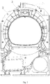
Fig. 1 is a structural schematic diagram of a clothes dryer (without the clothes drying drum and the door body) in the present disclosure. -
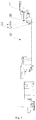
Fig. 2 is a structural schematic diagram of the front wind channel of the present disclosure. -
Fig. 3 is a sectional view ofFig. 2 . -
Fig. 4 is a schematic diagram of the front wind channel in another point of view. -
Fig. 5 is a schematic diagram of the front wind channel in another point of view. -
Fig. 6 is a schematic diagram of the front wind channel in another point of view. -
Fig. 7 is an enlarged view of part A inFig. 6 . - Reference numerals: 1, front wind channel, 2, drying bracket, 3, hook, 4, connecting part, 5, supporting part, 6, stiffened plate, 7, convex rib, 8, inner wall of the front wind channel, 9, central axis.
- As shown in
Fig. 1 to Fig. 7 , the present disclosure provides a clothes dryer which includes a clothes drying drum, afront wind channel 1 and a door body. The clothes drying drum is provided with adrying bracket 2 therein, thefront wind channel 1 is provided with ahook 3 for hanging thedrying bracket 2, and thehook 3 and thefront wind channel 1 are set in an integrated manner. One end of thedrying bracket 2 is connected onto thefront wind channel 1 in a hanging manner, and the other end is connected with the bottom of the clothes drying drum or the bottom of thefront wind channel 1. Thehook 3 and thefront wind channel 1 are set in an integrated manner. Under the premise of not influencing the mold stripping of thefront wind channel 1 and the normal use of thehook 3, the mold stripping manner of thefront wind channel 1 is improved, thereby eliminating the contradiction of the mold stripping directions of thehook 3 and thefront wind channel 1. The mold cost is reduced, the production efficiency is improved, and the intensity of the hook is improved. - The
hook 3 is arranged on the top of theinner wall 8 of the front wind channel, thereby reducing the scraping of clothes and avoiding the influence on the turnover of the clothes inside the drum. The opening of thehook 3 is toward the door body of the clothes dryer. When thedrying bracket 2 is arranged from the outside to the inside, the hanging part of thedrying bracket 2 is directly placed inside the opening of thehook 3 and is supported by thehook 3. The opening of thehook 3 is toward the door body of the clothes dryer, which facilitate the operation when users place thedrying bracket 2 from the outside to the inside. Meanwhile, the opening of thehook 3 is toward the door body of the clothes dryer, thereby avoiding hooking on the clothes to influence on the turnover of clothes inside the drum. - The
hook 3 includes a connectingpart 4 and a supporting part 5, the connectingpart 4 is formed by the extension of theinner wall 8 of the front wind channel towards the central axis direction of the clothes drying drum. The supporting part 5 is formed by the extension of the end part of the connectingpart 4 towards the door body direction along the central axis direction of the drum. Namely, thehook 3 is of an L shape in a sectional view. One side of the L shape and theinner wall 8 of the front wind channel are injection molded in an integrated manner to form the connectingpart 4, the other side of the L shape hangs in the air to form the supporting part 5 for hanging thedrying bracket 2, and forms an opening together with theinner wall 8 of the front wind channel. The opening is towards the door body. Such a structure is simple, and manufactured easily by integrated molding. The structure facilitates users in taking and placing the drying bracket, and ensures strength. - The inside of the
hook 3 is of a hollow structure, and the end of thehook 3 towards the clothes drying drum is of an open structure. Thehook 3 is internally provided with a stiffenedplate 6, and the stiffenedplate 6 is arranged along an axial direction. Preferably, the inside of the connectingpart 4 is of a hollow structure. The end part of the connectingpart 4 toward the clothes drying drum is of an open structure, and the connectingpart 4 is internally provided with a stiffenedplate 6. The stiffenedplate 6 is arranged along an axial direction. The stiffenedplate 6 enhances the connecting strength between thehook 3 and theinner wall 8 of the front wind channel. The overall size is smaller than that of the structure in which thehook 3 and thefront wind channel 1 are arranged in a separated manner. It is reduced in the possibility of scraping clothes and the consumption of raw materials. The arrangement along the axial direction does not influence the mold stripping in the manufacturing process. - The
inner wall 8 of the front wind channel, except the position in which thehook 3 is located, inclines towards the direction far away from thecentral axis 9 from the door body to the clothes drying drum. And theinner wall 8 of the front wind channel where thehook 3 is located inclines towards the direction far away from thecentral axis 9 direction from the connecting part to the door body. The angle of inclination is a draft angle, and preferably, the angle of inclination is in a range of 1°-3°. In the manufacturing process, the mold stripping direction of most of thefront wind channel 1 is from the door body to the clothes drying drum. Namely, except the mold stripping direction of thefront wind channel 1 in which thehook 3 is located is from the door body to the clothes drying drum , the mold stripping direction of the position in which thehook 3 is located is in a reversed direction, that is, from the clothes drying drum to the door body. - The supporting part 5 of the
hook 3 inclines towards the direction close to thecentral axis 9 from the connecting end connected with the connectingpart 4 to the opening end towards the door body, which is more convenient for the mold stripping of most of thefront wind channel 1 from the door body to the clothes drying drum , and for the mold stripping of the position in which thehook 3 is located from the clothes drying drum to the door body. Under the premise of not influencing the mold stripping of thefront wind channel 1 and the normal use of thehook 3, the mold stripping mode of thefront wind channel 1 is changed, thereby eliminating the contradiction of the mold stripping directions of the hook and the front wind channel. The front wind channel and the hook of the drying bracket are set in an integrated manner, thereby reducing the mold cost, improving the production efficiency, and improving the intensity of the hook. -
Convex ribs 7 are arranged between the inclined planes with different inclining directions on theinner wall 8 of the front wind channel, and theconvex ribs 7 are in smooth transition with the inclined planes on the two sides. Most of thefront wind channel 1 strips mold from the door body to the clothes drying drum , and the position in which thehook 3 is located strips mold from the clothes drying drum to the door body , on the two sides of thehook 3 along the axial direction, and the inclined planes with different inclining directions are intersected to form corner angles. In the present disclosure,convex ribs 7 are arranged at the intersection point of inclined planes with different inclining directions, one side of theconvex rib 7 is in smooth transition with the inclined plane which inclines toward the same direction, and the other side is in smooth transition with the inclined plane which inclines toward the other direction. And theconvex rib 7 changes two inclined planes which are connected vertically into two inclined planes in smooth transition, thereby avoiding the scraping of users on the clothes. - In the present disclosure, the
front wind channel 1 and thehook 3 are injection molded in an integrated manner, and the normal mold stripping of thefront wind channel 1 and thehook 3 are not influenced. As shown inFig. 6 andFig. 7 , the mold stripping directions in the X region and the Y region are opposite. The mold stripping in the Y region in the inner wall of the front wind channel is from the door body to the clothes drying drum, while the mold stripping in the X region is from the clothes drying drum to the door body, thereby solving the problem that mold cannot be stripped due to the integrated arrangement of thefront wind channel 1 and thehook 3. Meanwhile, the overall size in integrated arrangement is smaller than the size in which thehook 3 and thefront wind channel 1 are arranged in a split manner, thereby reducing the possibility of scraping clothes, and reducing the consumption of raw materials. - The forgoing are merely preferred embodiments of the present disclosure. It should be noted that, for those of ordinary skill in the art, under the premise of not departing from the present disclosure, various transformations and improvements can still be made, and such transformations and improvements shall also be deemed as falling within the protection scope of the present disclosure.
Claims (8)
- A clothes dryer, comprising a clothes drying drum, a front wind channel and a door body,
wherein the drying bracke is arranged in the clothes drying drum,
one end of the drying bracket is connected onto the front wind channel in a hanging manner,
the front wind channel is provided with a hook for connecting the drying bracket in a hanging manner, and
the hook and the front wind channel are set in an integrated manner. - The clothes dryer according to claim 1, wherein the hook is arranged on a top of an inner wall of the front wind channel, and an opening of the hook is toward the door body of the clothes dryer.
- The clothes dryer according to claim 1 or 2, wherein the hook comprises a connecting part and a supporting part,
the connecting part is formed by an extension of the inner wall of the front wind channel towards a central axis direction of the clothes drying drum, and
the supporting part is formed by an extension of an end of the connecting part towards the door body along the central axis direction of the clothes drying drum. - The clothes dryer according to any one of claims 1-3, wherein an inside of the hook is of a hollow structure,
an end of the hook towards the clothes drying drum is of an open structure,
the hook is internally provided with a stiffened plate, the stiffened plate is arranged along an axial direction, and
preferably, an inside of the connecting part is of a hollow structure, an end of the connecting part toward the clothes drying drum is of an open structure,
the connecting part is provided with a stiffened plate therein, and the stiffened plate is arranged along an axial direction. - The clothes dryer according to any one of claims 1-4, wherein the inner wall of the front wind channel, except a position in which the hook is located, inclines towards a direction far away from the central axis from the door body to the clothes drying drum, and
the inner wall of the front wind channel where the hook is located inclines towards a direction far away from the central axis direction from the connecting part to the door body. - The clothes dryer according to any one of claims 1-5, wherein the supporting part of the hook inclines towards adirection close to the central axis from the connecting end connected with the connecting part to the opening end towards the door body.
- The clothes dryer according to claim 5 or 6, wherein an angle of inclination is a draft angle, and
preferably, the angle of inclination is in a range of 1°-3°. - The clothes dryer according to any one of claims 1-7, wherein two sides of the hook on the inner wall of the front wind channel are inclined planes with different inclining directions,
convex ribs are arranged between the inclined planes with different inclining directions, and the convex ribs are in smooth transition with the inclined planes on the two sides.
Applications Claiming Priority (2)
| Application Number | Priority Date | Filing Date | Title |
|---|---|---|---|
| CN201510289865.9A CN106283559B (en) | 2015-05-29 | 2015-05-29 | a clothes dryer |
| PCT/CN2015/095303 WO2016192331A1 (en) | 2015-05-29 | 2015-11-23 | Clothes dryer |
Publications (2)
| Publication Number | Publication Date |
|---|---|
| EP3305974A1 true EP3305974A1 (en) | 2018-04-11 |
| EP3305974A4 EP3305974A4 (en) | 2018-07-11 |
Family
ID=57440065
Family Applications (1)
| Application Number | Title | Priority Date | Filing Date |
|---|---|---|---|
| EP15893975.1A Withdrawn EP3305974A4 (en) | 2015-05-29 | 2015-11-23 | Clothes dryer |
Country Status (4)
| Country | Link |
|---|---|
| EP (1) | EP3305974A4 (en) |
| KR (1) | KR20180014038A (en) |
| CN (1) | CN106283559B (en) |
| WO (1) | WO2016192331A1 (en) |
Families Citing this family (2)
| Publication number | Priority date | Publication date | Assignee | Title |
|---|---|---|---|---|
| CN109763309A (en) * | 2017-11-09 | 2019-05-17 | 青岛海尔洗衣机有限公司 | Drying bracket and clothes dryer including the same |
| CN111172703A (en) * | 2018-11-09 | 2020-05-19 | 青岛海尔滚筒洗衣机有限公司 | A clothes treatment device |
Family Cites Families (10)
| Publication number | Priority date | Publication date | Assignee | Title |
|---|---|---|---|---|
| JPS5077874A (en) * | 1973-11-14 | 1975-06-25 | ||
| JPS5249830Y2 (en) * | 1973-11-16 | 1977-11-11 | ||
| JPS5488973U (en) * | 1977-12-07 | 1979-06-23 | ||
| US6067723A (en) * | 1999-01-29 | 2000-05-30 | Maytag Corporation | Clothes dryer hanging feature |
| DE10360872A1 (en) * | 2003-12-23 | 2005-07-21 | BSH Bosch und Siemens Hausgeräte GmbH | Drying basket and fastening device for a drying basket on a tumble dryer |
| KR101225502B1 (en) * | 2005-10-20 | 2013-01-23 | 삼성전자주식회사 | Clothing dryer |
| CN201770870U (en) * | 2010-08-24 | 2011-03-23 | 松下家电研究开发(杭州)有限公司 | A bucket structure of a drum washing machine |
| KR101814527B1 (en) * | 2011-10-06 | 2018-01-05 | 주식회사 대유위니아 | Drying machine |
| EP3392394B1 (en) * | 2011-11-04 | 2020-12-02 | Arçelik Anonim Sirketi | A laundry dryer comprising a carrier |
| EP2712953A1 (en) * | 2012-10-01 | 2014-04-02 | V-Zug AG | Stationary holder for desiccation material in a laundry dryer with rotatable drying drum |
-
2015
- 2015-05-29 CN CN201510289865.9A patent/CN106283559B/en active Active
- 2015-11-23 EP EP15893975.1A patent/EP3305974A4/en not_active Withdrawn
- 2015-11-23 KR KR1020177037450A patent/KR20180014038A/en not_active Ceased
- 2015-11-23 WO PCT/CN2015/095303 patent/WO2016192331A1/en not_active Ceased
Also Published As
| Publication number | Publication date |
|---|---|
| WO2016192331A1 (en) | 2016-12-08 |
| CN106283559A (en) | 2017-01-04 |
| CN106283559B (en) | 2020-04-03 |
| KR20180014038A (en) | 2018-02-07 |
| EP3305974A4 (en) | 2018-07-11 |
Similar Documents
| Publication | Publication Date | Title |
|---|---|---|
| CN106283559B (en) | a clothes dryer | |
| WO2020164426A1 (en) | Wall-mounted washing machine | |
| CN203539020U (en) | Clothes hanger | |
| CN104305830A (en) | Self-locking clothes hanger | |
| CN105318332A (en) | An energy-gathering outer fire cover | |
| CN202359364U (en) | The lid of the vacuum bucket of the sewing machine | |
| CN204254849U (en) | Decorative plate assembling structure of cabinet air conditioner and cabinet air conditioner | |
| CN203411834U (en) | Clothes dryer | |
| CN207217938U (en) | A kind of built-in switch jack | |
| CN208645744U (en) | Extruding machine dehumidification device | |
| CN201087295Y (en) | Novel wind-proof clothes airing device | |
| CN207860876U (en) | A kind of tank bucket for storing material | |
| CN210177204U (en) | Airing rod | |
| CN216364691U (en) | A curtain rod with high stability | |
| CN207395282U (en) | A kind of air passage and refrigerator | |
| CN204238045U (en) | A kind of garment support of the suspended garment with shell fragment | |
| CN209941336U (en) | Clothes-horse convenient to put clothes hanger | |
| CN204717622U (en) | A kind of separated burner | |
| CN206423939U (en) | Practical clothes hanger with windproof lock | |
| CN204683261U (en) | A kind of wind-proof clothes hanger | |
| CN203367906U (en) | An octagonal lamp head box | |
| CN107119434A (en) | A kind of drying-type hat rack | |
| CN202913262U (en) | Remote control clotheshorse convenient to dismantle | |
| CN206062806U (en) | A kind of novel windproof clothes hanger | |
| CN219280303U (en) | Clothes support fixing sleeve |
Legal Events
| Date | Code | Title | Description |
|---|---|---|---|
| PUAI | Public reference made under article 153(3) epc to a published international application that has entered the european phase |
Free format text: ORIGINAL CODE: 0009012 |
|
| 17P | Request for examination filed |
Effective date: 20171228 |
|
| AK | Designated contracting states |
Kind code of ref document: A1 Designated state(s): AL AT BE BG CH CY CZ DE DK EE ES FI FR GB GR HR HU IE IS IT LI LT LU LV MC MK MT NL NO PL PT RO RS SE SI SK SM TR |
|
| AX | Request for extension of the european patent |
Extension state: BA ME |
|
| A4 | Supplementary search report drawn up and despatched |
Effective date: 20180611 |
|
| RIC1 | Information provided on ipc code assigned before grant |
Ipc: D06F 37/08 20060101ALN20180605BHEP Ipc: D06F 58/04 20060101AFI20180605BHEP |
|
| DAV | Request for validation of the european patent (deleted) | ||
| DAX | Request for extension of the european patent (deleted) | ||
| STAA | Information on the status of an ep patent application or granted ep patent |
Free format text: STATUS: THE APPLICATION IS DEEMED TO BE WITHDRAWN |
|
| 18D | Application deemed to be withdrawn |
Effective date: 20190109 |