EP3305887A1 - Concentrating device and method for concentrating cell suspension - Google Patents
Concentrating device and method for concentrating cell suspension Download PDFInfo
- Publication number
- EP3305887A1 EP3305887A1 EP16800018.0A EP16800018A EP3305887A1 EP 3305887 A1 EP3305887 A1 EP 3305887A1 EP 16800018 A EP16800018 A EP 16800018A EP 3305887 A1 EP3305887 A1 EP 3305887A1
- Authority
- EP
- European Patent Office
- Prior art keywords
- port
- bringing
- culture
- filtering device
- communication
- Prior art date
- Legal status (The legal status is an assumption and is not a legal conclusion. Google has not performed a legal analysis and makes no representation as to the accuracy of the status listed.)
- Granted
Links
Images









Classifications
-
- C—CHEMISTRY; METALLURGY
- C12—BIOCHEMISTRY; BEER; SPIRITS; WINE; VINEGAR; MICROBIOLOGY; ENZYMOLOGY; MUTATION OR GENETIC ENGINEERING
- C12M—APPARATUS FOR ENZYMOLOGY OR MICROBIOLOGY; APPARATUS FOR CULTURING MICROORGANISMS FOR PRODUCING BIOMASS, FOR GROWING CELLS OR FOR OBTAINING FERMENTATION OR METABOLIC PRODUCTS, i.e. BIOREACTORS OR FERMENTERS
- C12M47/00—Means for after-treatment of the produced biomass or of the fermentation or metabolic products, e.g. storage of biomass
- C12M47/02—Separating microorganisms from the culture medium; Concentration of biomass
-
- B—PERFORMING OPERATIONS; TRANSPORTING
- B01—PHYSICAL OR CHEMICAL PROCESSES OR APPARATUS IN GENERAL
- B01D—SEPARATION
- B01D61/00—Processes of separation using semi-permeable membranes, e.g. dialysis, osmosis or ultrafiltration; Apparatus, accessories or auxiliary operations specially adapted therefor
- B01D61/24—Dialysis ; Membrane extraction
- B01D61/243—Dialysis
-
- B—PERFORMING OPERATIONS; TRANSPORTING
- B01—PHYSICAL OR CHEMICAL PROCESSES OR APPARATUS IN GENERAL
- B01D—SEPARATION
- B01D63/00—Apparatus in general for separation processes using semi-permeable membranes
- B01D63/02—Hollow fibre modules
-
- B—PERFORMING OPERATIONS; TRANSPORTING
- B01—PHYSICAL OR CHEMICAL PROCESSES OR APPARATUS IN GENERAL
- B01D—SEPARATION
- B01D63/00—Apparatus in general for separation processes using semi-permeable membranes
- B01D63/02—Hollow fibre modules
- B01D63/04—Hollow fibre modules comprising multiple hollow fibre assemblies
-
- B—PERFORMING OPERATIONS; TRANSPORTING
- B01—PHYSICAL OR CHEMICAL PROCESSES OR APPARATUS IN GENERAL
- B01D—SEPARATION
- B01D63/00—Apparatus in general for separation processes using semi-permeable membranes
- B01D63/16—Rotary, reciprocated or vibrated modules
-
- C—CHEMISTRY; METALLURGY
- C12—BIOCHEMISTRY; BEER; SPIRITS; WINE; VINEGAR; MICROBIOLOGY; ENZYMOLOGY; MUTATION OR GENETIC ENGINEERING
- C12M—APPARATUS FOR ENZYMOLOGY OR MICROBIOLOGY; APPARATUS FOR CULTURING MICROORGANISMS FOR PRODUCING BIOMASS, FOR GROWING CELLS OR FOR OBTAINING FERMENTATION OR METABOLIC PRODUCTS, i.e. BIOREACTORS OR FERMENTERS
- C12M1/00—Apparatus for enzymology or microbiology
- C12M1/10—Apparatus for enzymology or microbiology rotatably mounted
-
- C—CHEMISTRY; METALLURGY
- C12—BIOCHEMISTRY; BEER; SPIRITS; WINE; VINEGAR; MICROBIOLOGY; ENZYMOLOGY; MUTATION OR GENETIC ENGINEERING
- C12M—APPARATUS FOR ENZYMOLOGY OR MICROBIOLOGY; APPARATUS FOR CULTURING MICROORGANISMS FOR PRODUCING BIOMASS, FOR GROWING CELLS OR FOR OBTAINING FERMENTATION OR METABOLIC PRODUCTS, i.e. BIOREACTORS OR FERMENTERS
- C12M23/00—Constructional details, e.g. recesses, hinges
- C12M23/02—Form or structure of the vessel
- C12M23/14—Bags
-
- C—CHEMISTRY; METALLURGY
- C12—BIOCHEMISTRY; BEER; SPIRITS; WINE; VINEGAR; MICROBIOLOGY; ENZYMOLOGY; MUTATION OR GENETIC ENGINEERING
- C12M—APPARATUS FOR ENZYMOLOGY OR MICROBIOLOGY; APPARATUS FOR CULTURING MICROORGANISMS FOR PRODUCING BIOMASS, FOR GROWING CELLS OR FOR OBTAINING FERMENTATION OR METABOLIC PRODUCTS, i.e. BIOREACTORS OR FERMENTERS
- C12M23/00—Constructional details, e.g. recesses, hinges
- C12M23/42—Integrated assemblies, e.g. cassettes or cartridges
-
- C—CHEMISTRY; METALLURGY
- C12—BIOCHEMISTRY; BEER; SPIRITS; WINE; VINEGAR; MICROBIOLOGY; ENZYMOLOGY; MUTATION OR GENETIC ENGINEERING
- C12M—APPARATUS FOR ENZYMOLOGY OR MICROBIOLOGY; APPARATUS FOR CULTURING MICROORGANISMS FOR PRODUCING BIOMASS, FOR GROWING CELLS OR FOR OBTAINING FERMENTATION OR METABOLIC PRODUCTS, i.e. BIOREACTORS OR FERMENTERS
- C12M23/00—Constructional details, e.g. recesses, hinges
- C12M23/44—Multiple separable units; Modules
-
- C—CHEMISTRY; METALLURGY
- C12—BIOCHEMISTRY; BEER; SPIRITS; WINE; VINEGAR; MICROBIOLOGY; ENZYMOLOGY; MUTATION OR GENETIC ENGINEERING
- C12M—APPARATUS FOR ENZYMOLOGY OR MICROBIOLOGY; APPARATUS FOR CULTURING MICROORGANISMS FOR PRODUCING BIOMASS, FOR GROWING CELLS OR FOR OBTAINING FERMENTATION OR METABOLIC PRODUCTS, i.e. BIOREACTORS OR FERMENTERS
- C12M23/00—Constructional details, e.g. recesses, hinges
- C12M23/50—Means for positioning or orientating the apparatus
-
- C—CHEMISTRY; METALLURGY
- C12—BIOCHEMISTRY; BEER; SPIRITS; WINE; VINEGAR; MICROBIOLOGY; ENZYMOLOGY; MUTATION OR GENETIC ENGINEERING
- C12M—APPARATUS FOR ENZYMOLOGY OR MICROBIOLOGY; APPARATUS FOR CULTURING MICROORGANISMS FOR PRODUCING BIOMASS, FOR GROWING CELLS OR FOR OBTAINING FERMENTATION OR METABOLIC PRODUCTS, i.e. BIOREACTORS OR FERMENTERS
- C12M29/00—Means for introduction, extraction or recirculation of materials, e.g. pumps
- C12M29/04—Filters; Permeable or porous membranes or plates, e.g. dialysis
-
- C—CHEMISTRY; METALLURGY
- C12—BIOCHEMISTRY; BEER; SPIRITS; WINE; VINEGAR; MICROBIOLOGY; ENZYMOLOGY; MUTATION OR GENETIC ENGINEERING
- C12M—APPARATUS FOR ENZYMOLOGY OR MICROBIOLOGY; APPARATUS FOR CULTURING MICROORGANISMS FOR PRODUCING BIOMASS, FOR GROWING CELLS OR FOR OBTAINING FERMENTATION OR METABOLIC PRODUCTS, i.e. BIOREACTORS OR FERMENTERS
- C12M3/00—Tissue, human, animal or plant cell, or virus culture apparatus
- C12M3/02—Tissue, human, animal or plant cell, or virus culture apparatus with means providing suspensions
-
- C—CHEMISTRY; METALLURGY
- C12—BIOCHEMISTRY; BEER; SPIRITS; WINE; VINEGAR; MICROBIOLOGY; ENZYMOLOGY; MUTATION OR GENETIC ENGINEERING
- C12M—APPARATUS FOR ENZYMOLOGY OR MICROBIOLOGY; APPARATUS FOR CULTURING MICROORGANISMS FOR PRODUCING BIOMASS, FOR GROWING CELLS OR FOR OBTAINING FERMENTATION OR METABOLIC PRODUCTS, i.e. BIOREACTORS OR FERMENTERS
- C12M3/00—Tissue, human, animal or plant cell, or virus culture apparatus
- C12M3/04—Tissue, human, animal or plant cell, or virus culture apparatus with means providing thin layers
- C12M3/043—Tissue, human, animal or plant cell, or virus culture apparatus with means providing thin layers rotatably mounted
-
- C—CHEMISTRY; METALLURGY
- C12—BIOCHEMISTRY; BEER; SPIRITS; WINE; VINEGAR; MICROBIOLOGY; ENZYMOLOGY; MUTATION OR GENETIC ENGINEERING
- C12M—APPARATUS FOR ENZYMOLOGY OR MICROBIOLOGY; APPARATUS FOR CULTURING MICROORGANISMS FOR PRODUCING BIOMASS, FOR GROWING CELLS OR FOR OBTAINING FERMENTATION OR METABOLIC PRODUCTS, i.e. BIOREACTORS OR FERMENTERS
- C12M3/00—Tissue, human, animal or plant cell, or virus culture apparatus
- C12M3/06—Tissue, human, animal or plant cell, or virus culture apparatus with filtration, ultrafiltration, inverse osmosis or dialysis means
-
- C—CHEMISTRY; METALLURGY
- C12—BIOCHEMISTRY; BEER; SPIRITS; WINE; VINEGAR; MICROBIOLOGY; ENZYMOLOGY; MUTATION OR GENETIC ENGINEERING
- C12M—APPARATUS FOR ENZYMOLOGY OR MICROBIOLOGY; APPARATUS FOR CULTURING MICROORGANISMS FOR PRODUCING BIOMASS, FOR GROWING CELLS OR FOR OBTAINING FERMENTATION OR METABOLIC PRODUCTS, i.e. BIOREACTORS OR FERMENTERS
- C12M3/00—Tissue, human, animal or plant cell, or virus culture apparatus
- C12M3/06—Tissue, human, animal or plant cell, or virus culture apparatus with filtration, ultrafiltration, inverse osmosis or dialysis means
- C12M3/065—Tissue, human, animal or plant cell, or virus culture apparatus with filtration, ultrafiltration, inverse osmosis or dialysis means with hollow fibres or tubes
-
- C—CHEMISTRY; METALLURGY
- C12—BIOCHEMISTRY; BEER; SPIRITS; WINE; VINEGAR; MICROBIOLOGY; ENZYMOLOGY; MUTATION OR GENETIC ENGINEERING
- C12M—APPARATUS FOR ENZYMOLOGY OR MICROBIOLOGY; APPARATUS FOR CULTURING MICROORGANISMS FOR PRODUCING BIOMASS, FOR GROWING CELLS OR FOR OBTAINING FERMENTATION OR METABOLIC PRODUCTS, i.e. BIOREACTORS OR FERMENTERS
- C12M41/00—Means for regulation, monitoring, measurement or control, e.g. flow regulation
- C12M41/48—Automatic or computerized control
-
- B—PERFORMING OPERATIONS; TRANSPORTING
- B01—PHYSICAL OR CHEMICAL PROCESSES OR APPARATUS IN GENERAL
- B01D—SEPARATION
- B01D2313/00—Details relating to membrane modules or apparatus
- B01D2313/06—External membrane module supporting or fixing means
-
- B—PERFORMING OPERATIONS; TRANSPORTING
- B01—PHYSICAL OR CHEMICAL PROCESSES OR APPARATUS IN GENERAL
- B01D—SEPARATION
- B01D2313/00—Details relating to membrane modules or apparatus
- B01D2313/10—Specific supply elements
-
- B—PERFORMING OPERATIONS; TRANSPORTING
- B01—PHYSICAL OR CHEMICAL PROCESSES OR APPARATUS IN GENERAL
- B01D—SEPARATION
- B01D2313/00—Details relating to membrane modules or apparatus
- B01D2313/12—Specific discharge elements
-
- B—PERFORMING OPERATIONS; TRANSPORTING
- B01—PHYSICAL OR CHEMICAL PROCESSES OR APPARATUS IN GENERAL
- B01D—SEPARATION
- B01D2315/00—Details relating to the membrane module operation
- B01D2315/02—Rotation or turning
-
- B—PERFORMING OPERATIONS; TRANSPORTING
- B01—PHYSICAL OR CHEMICAL PROCESSES OR APPARATUS IN GENERAL
- B01D—SEPARATION
- B01D2315/00—Details relating to the membrane module operation
- B01D2315/18—Time sequence of one or more process steps carried out periodically within one apparatus
-
- C—CHEMISTRY; METALLURGY
- C12—BIOCHEMISTRY; BEER; SPIRITS; WINE; VINEGAR; MICROBIOLOGY; ENZYMOLOGY; MUTATION OR GENETIC ENGINEERING
- C12M—APPARATUS FOR ENZYMOLOGY OR MICROBIOLOGY; APPARATUS FOR CULTURING MICROORGANISMS FOR PRODUCING BIOMASS, FOR GROWING CELLS OR FOR OBTAINING FERMENTATION OR METABOLIC PRODUCTS, i.e. BIOREACTORS OR FERMENTERS
- C12M29/00—Means for introduction, extraction or recirculation of materials, e.g. pumps
- C12M29/16—Hollow fibers
Definitions
- the present invention relates to a concentrator concentrating a cell suspension and a method for concentrating a cell suspension.
- Cell culture includes a process of transferring cells in a culture vessel to another culture vessel and a process of exchanging culture media in a culture vessel. Such processes of the cell culture need to be performed in an aseptic state. The cell culture is performed over several day to several weeks, and, during this period, each process is repeatedly performed. For the purpose of saving labor and culturing a large number of cells in cell culture, a device performing each process in cell culture is known (Patent Document 1).
- the concentration (number of cells per capacity) of cells in a cell suspension containing cultured cells is increased in some cases.
- a method for concentrating a cell suspension a method is known which uses a cell suspension treating device which has a hollow fiber separation membrane and is an inner pressure filtration system (Patent Document 2).
- a technique using a centrifugal separator as in a cell concentrator described in Patent Document 1 requires a space where a centrifugal separator is placed. Moreover, a space held in an aseptic state for moving a cell suspension from a culture vessel to a vessel suitable for centrifugal separation is required. Furthermore, a robot arm for treating a centrifugal separator requires a complicated motion, which has posed a problem that the device is complicated and the size increases.
- a cell suspension treating device described in Patent Document 2 is small as compared with the centrifugal separator but is not fully automated, and thus is not suitable for culturing and concentrating a large number of cells.
- the present invention has been made in view of the above-described circumstances. It is an object of the present invention to provide a means capable of simply concentrating a cell suspension.
- a cell suspension containing cells cultured in a culture vessel can be simply and efficiently concentrated.
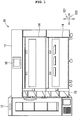
- a concentrator 10 has a control portion 11, a cold storage portion 12, a normal temperature storage portion 13, and two culture portions 14.
- the cold storage portion 12 and the normal temperature storage portion 13 are provided outside the culture portion 14.
- the two culture portions 14 are separately disposed upward and downward.
- the control portion 11 has a display 15.
- the display 15 is disposed on the front surface of the concentrator 10.
- the control portion 11 has a data input portion (not illustrated), and various conditions about cell culture and the like are input into the control portion 11 through the data input portion.
- the concentrator 10 is a device automatically culturing cells according to a program input and stored in the control portion 11.
- a vertical direction 101 is defined along the upper and lower sides in Fig. 1
- a lateral direction 102 is defined along the right and left sides in Fig. 1
- a forward and backward direction 103 is defined along a direction (direction perpendicular to the sheet surface of Fig. 1 ) perpendicular to the vertical direction 101 and the lateral direction 102.
- the control portion 11 has a rotation control portion 20, a culture control portion 21, and a supply/discharge control portion 22.
- the rotation control portion 20, the culture control portion 21, and the supply/discharge control portion 22 are arithmetic units for controlling an operation of a control target of each of the portions and store a program and information beforehand.
- the culture control portion 21 outputs control information to the rotation control portion 20 and the supply/discharge control portion 22.
- the culture control portion 21 outputs control information for controlling the environmental temperature of the culture portions 14.
- the rotation control portion 20 is electrically connected to the rotation mechanisms 34 and outputs the control information for controlling the drive of the rotation mechanisms 34.
- the supply/discharge control portion 22 is connected to a liquid supply/discharge mechanism 37 and outputs control information for driving actuators of the liquid supply/discharge mechanism 37, i.e., a supply pump 91, a discharge pump 92, and valves V1 to V18.
- the cold storage portion 12 is a case in which shelfs for placing vessels reserving a reagent or a culture medium therein are formed.
- a door capable of opening and closing an opening provided in the front surface of the case is provided.
- the cold storage portion 12 is a so-called refrigerator having a cooling mechanism (not illustrated).
- the temperature inside the cold storage portion 12 is kept at an arbitrary preset temperature, e.g., about 10°C or about 4°C, for example, lower than normal temperature by the cooling mechanism.
- the normal temperature storage portion 13 is a case having shelfs for placing vessels reserving a reagent or a culture medium therein.
- the vessels placed inside the cold storage portion 12 and the normal temperature storage portion 13 can reserve a reagent or a culture medium in a fluid tight manner.
- the vessels include a bag, a bottle, a cassette, and the like, for example.
- a tube and the like are connected so that a liquid therein can flow out, and thus a reserved liquid can be caused to flow out by the liquid supply/discharge mechanism 37.
- the two culture portions 14 have the same structure except a difference in the arrangement in the device, and therefore a detailed configuration thereof is described below taking one culture portion 14 as an example.
- the culture portion 14 is space formed inside the concentrator 10. The space is partitioned by a case frame of the concentrator 10 and a tray 17 ( Fig. 2 ).
- the tray 17 can be drawn to the front side from the front surface of the concentrator 10. By drawing of the tray 17, the culture portion 14 is opened, so that each configuration provided in the culture portion 14 can be accessed.
- the culture portion 14 can be held at predetermined temperature and CO 2 concentration. Although not illustrated in each figure, the culture portion 14 is provided with a warming device and a CO 2 supply device. Moreover, the culture portion 14 is provided with a temperature sensor and a CO 2 concentration sensor. The culture control portion 21 drives the warming device and the CO 2 supply device in order to set the inside of the culture portion 14 to set temperature and CO 2 concentration based on outputs of the temperature sensor and the CO 2 concentration sensor. In cell culture, the culture portion 14 can be held in an environment of 37°C and 5%CO 2 , for example.
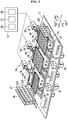
- the first bag holding portion 31, the second bag holding portion 32, and the third bag holding portion 33 are provided side by side in the lateral direction 102 in the tray 17.
- the rotation mechanism 34 is provided in the rear side in the forward and backward direction 103 of the first bag holding portion 31. By the rotation mechanism 34, the first bag holding portion 31 is rotated to a predetermined rotation position.
- the rotation mechanism 34 is provided in the rear side in the forward and backward direction 103 of the second bag holding portion 32 and the rotation mechanism 34 is provided in the rear side in the forward and backward direction 103 of the third bag holding portion 33.
- the liquid supply/discharge mechanism 37 is provided on the front side of the tray 17.
- a filtering device support portion 104 connected to the first bag holding portion 31 in such a manner as to be coaxially rotatable with the first bag holding portion 31 is provided.
- vessel storage portions 27 and 28 are provided on the left side in the lateral direction 102 of the tray 17 and a vessel storage portion 29 is provided on the right side in the lateral direction 102 of the tray 17.
- the first bag holding portion 31, the second bag holding portion 32, and the third bag holding portion 33 basically have the same configuration except a difference in the arrangement and the size, and therefore a detailed configuration is described taking the third bag holding portion 33 as an example.
- the outer shapes and the sizes of the first bag holding portion 31, the second bag holding portion 32, and the third bag holding portion 33 are designed according to the outer shape of a culture bag which can be held.
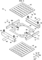
- the third bag holding portion 33 has holding plates 42 and 43, holders 44 and 45, spacers 46 and 47, and rotating shafts 48 and 49.
- the holding plates 42 and 43 are rectangular plates. In the holding plates 42 and 43, a plurality of holes penetrating in the thickness direction is formed. The holes increase the heat conduction from gas in the culture portion 14 to the culture bag 90 sandwiched between the holding plates 42 and 43 to be held.
- the holding plates 42 and 43 are disposed facing each other.
- the surfaces facing each other in the holding plates 42 and 43 are supporting surfaces 65 and 66.
- a distance sensor 67 is disposed on the spacer 47.
- a magnet 68 is disposed facing the distance sensor 67.
- the distance sensor 67 outputs a voltage according to the magnetic flux density from the magnet 68, and a hall element is used, for example.
- the control portion 11 stores a threshold value beforehand.
- the threshold value is a value for judging that the distance between the holding plate 42 and the spacer 47 increases to reach a fixed value or above.
- the control portion 11 can judge that the distance between the holding plate 42 and the spacer 47 increases to reach a fixed value or above by comparing an output of the distance sensor 67 with the threshold value.
- the distance sensor 67 may be provided in the spacer 46 instead of the spacer 47 or may be provided in both the spacers 46 and 47.
- the magnet 68 may be provided in either the holding plate 42 or 43 insofar as the magnetic flux is detectable by the distance sensor 67.
- the arrangements of the distance sensor 67 and the magnet 68 are relative. It is a matter of course that the arrangement of the distance sensor 67 and the arrangement of the magnet 68 may be switched.
- the distance sensor 67 and the magnet 68 may be disposed facing each other in the holding plates 42 and 43.
- the spacers 46 and 47 are disposed in a pair of edge portions facing each other which are located between the holding plates 42 and 43 and in which ports 73 and 74 of the culture bag 90 (an example of the culture vessel) are disposed.
- the spacers 46 and 47 maintain the interval between the holding plates 42 and 43.
- the spacers 46 and 47 each have a square pole shape.
- the length in the longitudinal direction of the spacers 46 and 47 is almost the same as the length of the pair of edge portions of the holding plates 42 and 43.
- the cross-sectional shape of the spacers 46 and 47 is fixed over a longitudinal direction. In the center in the longitudinal direction of the spacers 46 and 47, recessed portions 46A and 47A recessed in a direction orthogonal to the longitudinal direction are formed.
- the recessed portions 46A and 47A are space into which tubes 99 of the culture bag 90 each are inserted.
- the spacers 46 and 47 may be integrally configured with one of the holding plates 42 and 43.
- the holders 44 and 45 sandwich the holding plates 42 and 43 in a state where the spacers 46 and 47 are present therebetween to integrally hold the same.
- the holders 44 and 45 are long and narrow members having a cross section of a lateral U-shape. Into the inside of the lateral U-shape, edge portions of the holding plates 42 and 43 in the state where the spacers 46 and 47 are present therebetween are inserted. The edge portions of the holding plates 42 and 43 to be inserted into the holders 44 and 45 are a pair of edge portions where the spacers 46 and 47 are not present.
- screw holes are formed, and screws 18 are screwed into the screw holes.
- the tip of the screws 18 is projected to the inside of the lateral U-shape of the holders 44 and 45. Due to the fact that one of the holders 44 and 45 inserted into the lateral U-shape of the holders 44 and 45 is pressurized by the screws 18, the holders 44 and 45 hold the holding plates 42 and 43 in the state where the spacers 46 and 47 are present therebetween. In this state, space formed between the supporting surfaces 65 and 66 of the holding plates 42 and 43 serves as space holding a culture bag.
- the holders 44 and 45 may be integrally configured with one of the holding plates 42 and 43.
- the holding plates 42 and 43 may be turnably connected by one of the holders 44 and 45 as in a hinge.
- the holders 44 and 45 are provided with rotating shafts 48 and 49, respectively, which are projected from the vicinity of the center in the longitudinal direction to the side opposite to the side where the holding plates 42 and 43 are held.
- the rotating shafts 48 and 49 coaxially extend in the state where the holders 44 and 45 hold the holding plates 42 and 43.
- the direction where the rotating shafts 48 and 49 extend is in parallel to the supporting surfaces 65 and 66 of the holding plates 42 and 43.
- the culture bag 90 in the case where a liquid is not contained in the culture bag 90 supported by the third bag holding portion 33 when the third bag holding portion 33 is in a state where the supporting surface 66 is located downward relative to the supporting surface 65 and the supporting surfaces 65 and 66 are in parallel with the horizontal direction, the culture bag 90 mainly contacts the supporting surface 66.
- the distance between the supporting surfaces 65 and 66 is a distance D1.
- a liquid of a capacity with which the holding plates 42 and 43 are not bent is caused to flow in the culture bag 90.
- Such a liquid amount is set as the amount of a liquid which can be reserved in the culture bag 90 beforehand.
- the culture bag 90 in contact with the supporting surfaces 65 and 66 further expands to bend the holding plates 42 and 43 in such a manner as to be spread out in a direction of separating from each other. Due to the bending of the holding plates 42 and 43, the distance between the supporting surfaces 65 and 66 increases (Distance D2).
- the control portion 11 judges that the distance between the supporting surfaces 65 and 66 exceeds the distance D2.
- first bag holding portion 31 and the second bag holding portion 32 are not described in detail with reference to the drawings but have holding plate holders and spacers as with the third bag holding portion 33.
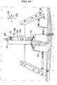
- a filtering device support portion 104 is disposed in the rear side in the forward and backward direction 103 of the first bag holding portion 31.
- the filtering device support portion 104 is integrally connected to the first bag holding portion 31. Therefore, the filtering device support portion 104 rotates integrally with the first bag holding portion 31 around the rotating shafts 48 and 49.
- the filtering device support portion 104 supports a filtering device 120.
- the filtering device 120 supported by the filtering device support portion 104 is disposed so that an inflow port 110 and a first outflow port 111 each face a direction crossing (in this embodiment, direction orthogonal to) the rotation axis by the rotating shafts 48 and 49.
- openings 17A are formed in three places in the tray 17 in the portions where the first bag holding portion 31, the second bag holding portion 32, the third bag holding portion 33, and the filtering device support portion 104 are disposed in order to avoid interference with the first bag holding portion 31, the second bag holding portion 32, the third bag holding portion 33, and the filtering device support portion 104 which are rotating.
- a pair of bearing portions 24 is individually disposed.
- the pair of bearing portions 24 rotatably supports each of the rotating shafts 48 and 49 of the first bag holding portion 31, the second bag holding portion 32, the third bag holding portion 33, and the filtering device support portion 104 in the state in parallel with the forward and backward direction 103.
- each of the holding plates 42 and 43 of the first bag holding portion 31, the second bag holding portion 32, and the third bag holding portion 33 and the filtering device support portion 104 can be rotated around the rotating shafts 48 and 49 as the rotation center.
- each bearing portion 24 is placed on each weight detector 23 provided on the tray 17.
- a pair of weight detectors 23 corresponding to each of the first bag holding portion 31, the second bag holding portion 32, or the third bag holding portion 33 the weights of the corresponding bag holding portion, a culture bag held by the corresponding bag holding portion, the bearing portion 24, and the like are detected.
- a load cell converting power (weight) applied to the weight detector 23 to an electric signal or the like is used, for example.
- the rotation mechanism 34 is provided in the rear side in the forward and backward direction 103 of each bearing portion 24 in the tray 17.
- the rotation mechanism 34 has a rotation shaft support portion 16 and a stepping motor (not illustrated).
- the rotation shaft support portion 16 extends toward the rear side in the forward and backward direction 103 and is coaxially connected to the rotating shaft 49 supported by each bearing portion 24.
- power is supplied to the stepping motor from a power supply.
- drive is transmitted to the stepping motor and the rotation shaft support portion 16 by a known speed reduction gear or the like.
- the rotation shaft support portion 16 rotates by only a predetermined rotation angle.
- the stepping motor may be provided with a sensor for detecting the original point position, i.e., the rotation position where the supporting surfaces 65 and 66 of the holding plates 42 and 43 of the first bag holding portion 31, the second bag holding portion 32, and the third bag holding portion 33 are in parallel with the horizontal direction.
- the rotation control portion 20 can drive the stepping motor so that the supporting surfaces 65 and 66 are in parallel with the horizontal direction based on the output of this sensor.
- the stepping motor can be driven so that the inflow port 110 and the first outflow port 111 of the filtering device 120 extend in the horizontal direction.
- the stepping motor is an example of a driving source of the rotation mechanism 34 and the other driving sources, such as a DC motor having an encoder capable of detecting the rotation amount, may be used, for example, in replace of the stepping motor.
- the rotation position of the driving source may be detected by other detection means, such as a resolver, or a sensor capable of directly detecting the rotation position of the first bag holding portion 31 and the like may be provided.
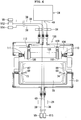
- the liquid supply/discharge mechanism 37 has a supply pump 91, a discharge pump 92, and a plurality of valves V1 to V18.
- the supply pump 91 and the discharge pump 92 known substances capable of sending a liquid in a tube are used. Examples of such a pump include a so-called tube pump sending liquid by squeezing an elastic tube with a turning roller, for example.
- Power is supplied to the supply pump 91 and the discharge pump 92 from the power supply.
- the supply/discharge control portion 22 can drive the supply pump 91 and the discharge pump 92 for a definite period of time by controlling the power supplied to the supply pump 91 and the discharge pump 92.
- the plurality of valves V1 to V18 are roughly classified into the valves V1 to V11 relating to the supply pump 91 and the valves V12 to V18 relating to the discharge pump 92.
- the supply pump 91 and the valves V1 to V11 are a liquid supply mechanism 81 in the liquid supply/discharge mechanism 37 and the discharge pump 92 and the valves V12 to V18 are a liquid discharge mechanism 82 in the liquid supply/discharge mechanism 37.
- ON/OFF is switched based on a control signal output from the supply/discharge control portion 22.
- the valves V1 to V18 are examples of the switching mechanism.
- an electromagnetic valve is used, for example.
- a culture circuit has three culture bags 70, 80, and 90, two server bags 39 and 40 (one example of the first reservoir), a collection bag 41 (one example of the collection vessel), the filtering device 120, reservoirs 116 and 117 (one example of the second reservoir and the third reservoir) held by the cold storage portion 12 or the normal temperature storage portion 13, and a plurality of tubes 38 connecting them so that a liquid can flow.
- the culture bag 70 is disposed in the first bag holding portion 31.
- the culture bag 80 is disposed in the second bag holding portion 32.
- the culture bag 90 is disposed in the third bag holding portion 33.
- the filtering device 120 is disposed in the filtering device support portion 104.
- the collection bag 41 is disposed in the culture portion 14.
- the culture bags 70, 80, and 90 have the same configuration except that the capacity of the culture bag 70 is smaller than that of the culture bags 80 and 90, and therefore a detailed configuration is described below taking the culture bag 90 as an example.
- the culture bag 90 is formed into a bag shape by bonding peripheral edges of two rectangular sheets formed of a synthetic resin by known methods, such as thermal welding.
- the tubes 99 formed of a synthetic resin are disposed near the center of each of a pair of end portions 77 and 78 facing each other in the two rectangular sheets.
- a notch portion 105 is formed toward edges 87 and 88 from the ends located in the internal space 75 of the culture bag 90 as illustrated in Figs. 9(A) and 9(B) .
- the notch portion 105 is located in a portion not facing inner surfaces 71 and 72 demarcating the internal space 75 of the culture bag 90, i.e., a place facing end portions other than the pair of end portions 77 and 78 in the two rectangular sheets, as illustrated in Fig. 10 . Even when it is supposed that, when a liquid is caused to flow out of the culture bag 90, the inner surfaces 71 and 72 are brought close to each other by a negative pressure arising in the internal space 75, the inner surfaces 71 and 72 are difficult to contact each other near the tubes 99 due to the fact that the tubes 99 are present between the inner surfaces 71 and 72.
- notch portion 105 is formed in a place not facing the inner surfaces 71 and 72 in the tubes 99, a liquid remaining near the edges 87 and 88 of the internal space 75 can flow in the internal space of the tubes 99 through the notch portions 105.
- the internal space 75 of the culture bag 90 is brought into communication with the outside through the internal space of the tubes 99. More specifically, the ports 73 and 74 are formed by the tubes 99.
- the edges 87 and 88 where the tubes 99 are disposed of the edges demarcating the internal space 75 of the culture bag 90 have a tapered shape in which the distance between the edges 87 and 88 decreases as separating from the ports 73 and 74. In other words, the edges 87 and 88 have a shape of expanding to the outside of the culture bag 90 toward the center where the tubes 99 are disposed.
- the tubes 99 extend in a direction orthogonal to the rotating shafts 48 and 49. More specifically, the ports 73 and 74 extend in the direction orthogonal to the rotating shafts 48 and 49.
- the synthetic resin sheet for use in the culture bag 90 has flexibility and has bending rigidity with which the bag shape can be maintained when a culture medium is placed therein.
- low density polyethylene, ultrahigh molecular weight polyethylene, cyclic polyolefin resin, and those having a laminated structure with the materials above or other materials are mentioned.
- the inner surfaces 71 and 72 of the culture bag 90 have cell adhesiveness suitable for culturing adhesive cells.
- cell adhesive functional groups are exposed by plasma treatment or the like, for example, in the inner surfaces 71 and 72.
- the cell adhesive functional group include an amino group, an amine group, a hydroxyl group, a sulfone group, a sulfen group, a sulfin group, an ether group, a carboxyl group, a carbonyl group, and the like, for example.
- an amino group and a carboxyl group having high adhesiveness with cells are preferable.
- the server bags 39 and 40, the collection bag 41, and the reservoirs 116 and 117 illustrated in Fig. 3 are formed into a bag shape by bonding synthetic resin sheets and have at least one of ports 94 to 98 (one example of the third port, the fourth port, the fifth port, and the sixth port).
- the server bags 39 and 40 reserve a culture medium.
- the collection bag 41 collects a cell suspension.
- the reservoirs 116 and 117 reserve a peeling liquid and a priming liquid.
- known vessels capable of reserving a culture medium and a cell suspension are usable besides known bags.
- tubes 38 are individually connected to each port of the culture bags 70, 80, and 90, the server bags 39 and 40, the collection bag 41, and the reservoirs 116 and 117.
- Each tube 38 connected to one port 73 of each of the culture bags 70, 80, and 90, the tube 38 connected to the inflow port 110 of the filtering device 120, each tube 38 connected to each of the ports 94 and 95 of the server bags 39 and 40, and each tube 38 connected to each of the ports 97 and 98 of the reservoirs 116 and 117 is extended to the supply pump 91.
- These tubes 38 are integrated into one tube 38 through a connector before reaching the supply pump 91 to configure a liquid supply circuit.
- the tubes 38 each are passed through the valves V6 to V11 before integrated into one tube 38 and the valves V6 to V11 can change the internal space of each tube 38 to an opened state where a liquid can flow and a closed state where a liquid cannot flow.
- Each tube 38 connected to the other port 74 of each of the culture bags 70, 80, and 90, each tube 38 connected to the first outflow port 111 and a second outflow port 112 of the filtering device 120, and the tube 38 connected to the port 96 of the collection bag 41 are extended to the discharge pump 92.
- These tubes 38 are integrated into one tube 38 before reaching the discharge pump 92 through a connector to configure a liquid discharge circuit.
- the tubes 38 each are passed through the valves V12 and V14 to V18 before integrated into one tube 38 and the valves V12 and V14 to V18 can change the internal space of each tube 38 to an opened state where a liquid can flow and a closed state where a liquid cannot flow.
- each tube 38 leading to the supply pump 91 is branched again, and then each tube 38 is connected to bags and vessels placed in the cold storage portion 12 or the normal temperature storage portion 13 through the valves V1 to V5. These bags and the vessels reserve a cell suspension, a culture medium, a peeling liquid, and the like.
- the tube 38 leading to the discharge pump 92 is connected to a waste liquid vessel 19.
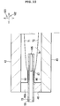
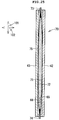
- the filtering device 120 has a body 106 (one example of the case), a cap 107, a cap 108, and a hollow fiber bundle 109 (one example of the filtration membrane).
- the body 106 has an approximately cylindrical shape.
- the body 106 is opened in both sides in the axial direction (direction along the vertical direction in Fig. 7 (A) ).
- the cap 107 and the cap 108 are screwed into each opening of the body 106.
- the inflow port 110 bringing the internal space and the external space of the filtering device 120 into communication with each other is formed so as to extend along the axial direction of the body 106.
- the first outflow port 111 bringing the internal space and the external space of the filtering device 120 into communication with each other is formed so as to extend along the axial direction of the body 106.
- a pair of hollow fiber supports (not illustrated) is formed near each opening of the body 106.
- the hollow fiber bundle 109 is supported by the pair of hollow fiber supports to be disposed in the internal space of the body 106. Both ends of the hollow fiber bundle 109 are disposed near the openings of the body 106.
- the hollow fiber supports support both the ends of the hollow fiber bundle 109 and separates both the ends of the hollow fiber bundle 109 and the internal space of the body 106 in a fluid tight manner. Therefore, a liquid flowing into the internal space of the body 106 through the inflow port 110 of the cap 107 flows into one end of a hollow fiber bundle 114 and does not flow in the space demarcated by the pair of hollow fiber supports in the internal space of the body 106.
- a liquid flowing out of the other end of the hollow fiber bundle 109 flows out of the first outflow port 111 of the cap 108 to the outside and a liquid does not flow in the first outflow port 111 from the space demarcated by the pair of hollow fiber supports in the internal space of the body 106.
- the second outflow port 112 extends in a direction orthogonal to the axial direction (direction along the vertical direction in Fig. 7 ) of the body 106 on the side where the cap 108 is screwed and the port 113 extends in a direction orthogonal to the axial direction of the body 106 on the side where the cap 107 is screwed.
- the second outflow port 112 and the port 113 bring the space demarcated by the pair of hollow fiber supports in the internal space of the body 106 and the outside of the body 106 into communication with each other.
- a liquid flowing out of the hollow fiber bundle 109 by filtering is caused to flow out to the outside through the second discharge port 112.
- the port 113 is sealed in this embodiment.
- the tubes 38 described above are connected to the inflow port 110, the first outflow port 111, and the second outflow port 112.
- the hollow fiber bundle 109 is a bundle of hollow fibers in which a dialysis membrane is formed into a tubular shape.
- the hollow fibers each are opened in both ends thereof.
- raw materials of the hollow fibers include triacetate, polyether sulfone, and the like.
- the thickness, film thickness, pore size, length, type, and the like of the hollow fibers are set as appropriate according to the conditions, such as a size, of cells to be filtered in the filtering device 120.
- the cell culture using the concentrator 10 can be performed by arbitrarily selecting any one or a plurality of the culture bags 70, 80, and 90 but, hereinafter, a cell culture method using only the culture bag 70 is described.
- the cell culture method using the concentrator 10 includes each step described below.
- a culture circuit is set beforehand.
- the culture bags 70, 80, and 90 are set in the first bag holding portion 31, the second bag holding portion 32, and the third bag holding portion 33, respectively
- the filtering device 120 is set in the filtering device support portion 104
- the server bags 39 and 40 are held by the vessel storage portions 27 and 28, respectively
- the collection bag 41 is held by the vessel storage portion 29.
- the reservoirs 116 and 117 are held by the cold storage portion 12 or the normal temperature storage portion 13.
- the tubes 38 of the circuit are set in the valves V1 to V18, the supply pump 91, and the discharge pump 92.
- a user sets beforehand the culture control portion 21 so that the culture step , the culture medium exchanging step, the culture step , the cell suspension concentrating step, and the cell suspension collecting step are successively performed.
- a user also sets beforehand various settings, such as the culture time in the culture step, the culture medium exchange amount in the culture medium exchanging step, the concentration time and the culture medium supply amount in the cell suspension concentrating step, and the reaction time with a peeling liquid in the cell suspension collecting step.
- the culture control portion 21 outputs a first information containing various setting information in the culture step, outputs a second information containing various setting information in the culture medium exchanging step, and outputs a third information containing various setting information in the cell suspension collecting step.
- the culture control portion 21 outputs various setting information in the cell suspension concentrating step.
- the rotation control portion 20 controls the drive of the rotation mechanism 34 based on each information output from the culture control portion 21.
- the supply/discharge control portion 22 controls the drive of the liquid supply/discharge mechanism 37 (liquid supply mechanism 81 and liquid discharge mechanism 82) based on each information output from the culture control portion 21.
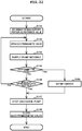
- the culture portion 14 in the concentrator 10 performs a preliminary operation due to the fact that the culture control portion 21 receives an input of start of culture.
- the temperature of the culture portion 14 is adjusted to 37°C and the carbon dioxide concentration is adjusted to 5% (Step S11).
- the rotation control portion 20 judges whether the first bag holding portion 31 is in the first position (Step S12).
- Step S12 When the rotation control portion 20 judges that the first bag holding portion 31 is not in the first position, i.e., the stepping motor in the rotation mechanism 34 is not located at the original point position (Step S12: No), the rotation control portion 20 rotates the stepping motor of the rotation mechanism 34 until the stepping motor reaches the original point position.
- the first bag holding portion 31 stops at the first position in which the supporting surfaces 65 and 66 are in parallel with the horizontal direction (Step S13).
- the rotation control portion 20 does not drive the rotation mechanism 34.
- the supporting surfaces 65 and 66 in the first position may be almost in parallel with the horizontal direction and do not need to be strictly in parallel with the horizontal direction.
- the valves V1 to V18 bring the tubes 38 into the closed state.
- the supply/discharge control portion 22 supplies a cell suspension to the culture bag 70 (Step S14).
- the supply of the cell suspension to the culture bag 70 is performed according to the liquid supply step.
- the weight detector 23 detects the weight of the culture bag 70 and the first bag holding portion 31.
- the control portion 11 sets a first reference value (Step S121).
- the control portion 11 calculates a value obtained by adding the weight of a cell suspension to be supplied to the culture bag 70 to the first reference value as a first target value.
- the weight of a liquid to be supplied to the culture bag 70 can be calculated based on the capacity of a cell suspension to be supplied to the culture bag 70. Assuming that the specific gravity of various liquids, such as a cell suspension, a culture medium, and a peeling liquid, is approximately 1, it may be regarded that the capacity (mL) and the weight (g) are equal.
- Step S14 the cell suspension is supplied to the culture bag 70 but Step S14 may be omitted and a cell suspension may be manually charged into the culture bag 70 beforehand.
- the supply/discharge control portion 22 drives the liquid supply mechanism 81 to supply a liquid to the culture bag 70.
- the valves V6 and V9 are brought into the opened state (Step S122).
- the supply pump 91 is driven (Step S123).
- the server bag 40 reserves beforehand a cell suspension containing cells to be cultured. Therefore, the cell suspension is supplied from the server bag 40 to the culture bag 70 through the port 73. While the cell suspension is being supplied to the culture bag 70, i.e., while the supply pump 91 is being driven, the control portion 11 monitors whether an output value of the distance sensor 67 exceeds a preset threshold value (Step 124).
- Step 124 When the control portion 11 judges that an output value of the distance sensor 67 exceeds the threshold value (Step 124: Yes), the control portion 11 issues an alarm by generating a buzzer sound or turning on a light (Step S126). Then, the supply/discharge control portion 22 stops the supply pump 91 (Step S128).
- the control portion 11 monitors whether preset time has passed after the supply pump 91 is driven (Step 125). As the time, time longer than time enough for the supply pump 91 to supply a maximum amount of liquid to the culture bag 70 is set. When the control portion 11 judges that the preset time has passed after the supply pump 91 is driven (Step 125: Yes), the control portion 11 issues an alarm in the same manner as above (Step S126), and then the supply/discharge control portion 22 stops the supply pump 91 (Step 128).
- the control portion 11 monitors whether an output value of the weight detector 23 has reached the first target value while the supply pump 91 is being driven (Step 127).
- the control portion 11 judges that the output value of the weight detector 23 has reached the first target value (Step 127: Yes)
- the supply/discharge control portion 22 stops the supply pump 91 (Step S128) to bring the valves V6 and V9 into the closed state (Step S129).
- the supply (liquid supply step) of the cell suspension to the culture bag 70 is completed (Step S14).
- the rotation control portion 20 drives the rotation mechanism 34 to rotate the first bag holding portion 31 counterclockwise by 90°.
- the first bag holding portion 31 is brought into a third position where the supporting surfaces 65 and 66 are in parallel with the vertical direction, the port 74 is located upward, and the port 73 is located downward (Step S15).
- gas entering the internal space 75 gathers. Since the edge 88 has the tapered shape toward the port 74, the gas moving along the edge 88 gathers to the port 74.
- the supporting surfaces 65 and 66 in the third position may be in parallel with the approximately vertical direction and do not necessarily need to be strictly in parallel with the vertical direction.
- the first bag holding portion 31 is brought into the third position, and then the supply/discharge control portion 22 brings the valves V6 and V9 into the closed state and brings the valves V13 and V15 into the opened state. Subsequently, the supply/discharge control portion 22 drives the discharge pump 92. Thus, a liquid or gas is discharged from the port 74 of the culture bag 70. When the gas remains in the internal space 75 of the culture bag 70 when a cell suspension is supplied to the culture bag 70, the gas is discharged from the internal space 75 through the port 74 (Step S16). Thus, a preliminary operation is completed.
- the culture control portion 21 successively performs the culture step (Step S17), the culture medium exchanging step (Step S18), the culture step (Step S19), and the cell suspension collecting step (Step S20). The details of each step are described later.
- a direction of performing subculture is input into the culture control portion 21 after the cell suspension collecting step (Step S21: Yes)
- a cell suspension collected by the other culture bags 80 and 90 is supplied in order to perform the subculture (Step S22).
- Step S22 No
- the culture control portion 21 does not perform subculture.
- a cell suspension concentrating step (Step S23) is performed.
- the culture control portion 21 outputs the first information to the rotation control portion 20 and the supply/discharge control portion 22.
- the rotation control portion 20 drives the rotation mechanism 34 to bring the first bag holding portion 31 into the first position (Step S24).
- the inner surface 71 is located upward and the inner surface 72 is located downward in the culture bag 70.
- the internal space 75 of the culture bag 70 reserves a cell suspension containing cells to be cultured and a culture medium. In the internal space 75, the cells descend in the cell suspension by gravity to contact the inner surface 72. Thus, the cells adhere to the inner surface 72 to be cultured.
- the rotation control portion 20 maintains the first bag holding portion 31 in the first position until the preset time passes (Step S25: No). After the preset time has passed (Step S25: Yes), the rotation control portion 20 drives the rotation mechanism 34 to rotate the first bag holding portion 31 clockwise by 180° as viewed from the front of the concentrator 10 (Step S26).
- the first bag holding portion 31 is brought into a fourth position in which the supporting surfaces 65 and 66 are in parallel with the horizontal direction, the inner surface 72 of the culture bag 70 is located upward, and the inner surface 71 is located downward.
- the rotation control portion 20 maintains the first bag holding portion 31 in the fourth position until the preset time passes (Step S27: No). When the preset time has passed, the culture step is completed (Step S27: Yes).
- the culture control portion 21 outputs the second information to the rotation control portion 20 and the supply/discharge control portion 22.
- the valve V1 and the valve V7 through which the tubes 38, which are connected to the reservoir 117 reserving a fresh culture medium stored in the cold storage portion 12 or the normal temperature storage portion 13, are passed are brought into the opened state, and then the supply pump 91 is driven to supply the fresh culture medium to the server bag 39.
- the supply/discharge control portion 22 stops the supply pump 91, brings the valve V1 into the closed state, and then brings the valve V6 into the opened state.
- the supply/discharge control portion 22 brings the valves V6 and V7 through which the tubes 38, which are connected to the server bags 39 and 40, are passed into the opened state, and then reversely drives the supply pump 91 to supply a fresh culture medium to the server bag 40. Thereafter, the supply/discharge control portion 22 stops the supply pump 91, and then brings the valves V6 and V7 into the closed state. The fresh culture medium is held in the server bag 40 to be warmed to 37°C.
- the rotation control portion 20 drives the rotation mechanism 34 to rotate the first bag holding portion 31 in the first position clockwise by 30° as viewed from the front of the concentrator 10.
- the first bag holding portion 31 is brought into the second position in which the acute angle formed by the supporting surfaces 65 and 66 with respect to the horizontal direction is 30° and the port 73 is located upward and the port 74 is located downward (Step S31).
- the acute angle formed by the supporting surfaces 65 and 66 with respect to the horizontal direction is not limited to 30° and may be arbitrarily set insofar as the supporting surfaces 65 and 66 are not in parallel with the horizontal direction and the vertical direction.
- the acute angle formed by the supporting surfaces 65 and 66 with respect to the horizontal direction is 20° or more and 70° or less. More preferably, the acute angle is 30° or more and 60° or less.
- the supply/discharge control portion 22 discharges the culture medium from the culture bag 70 (Step S32).
- the discharge of the culture medium from the culture bag 70 is performed according to the liquid supply step.
- the weight detector 23 detects the weights of the culture bag 70 and the first bag holding portion 31.
- the control portion 11 sets a second reference value (Step S141).
- the control portion 11 calculates a value obtained by subtracting the weight of a culture medium to be discharged from the culture bag 70 from the second reference value as a second target value.
- the supply/discharge control portion 22 drives the liquid discharge mechanism 82 to discharge the culture medium from the culture bag 70.
- the valves V13 and V15 are brought into the opened state (Step S142).
- the discharge pump 92 is driven (Step S143).
- the control portion 11 monitors whether the preset time has passed after the discharge pump 92 is driven (Step S144). As the time, time longer than time enough for the discharge pump 92 to discharge the half amount of a liquid from the culture bag 70 is set.
- Step 144 When the control portion 11 judges that the preset time has passed after the discharge pump 92 is driven (Step 144: Yes), the control portion 11 issues an alarm in the same manner as above (Step S145), and then the supply/discharge control portion 22 stops the discharge pump 92 (Step 147).
- the control portion 11 monitors whether the output value of the weight detector 23 has reached the second target value while the discharge pump 92 is being driven (Step 146).
- the supply/discharge control portion 22 stops the discharge pump 92 (Step S147) and brings the valves V13 and V15 into the closed state (Step S148).
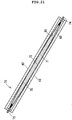
- the half of the culture medium reserved in the culture bag 70 is discharged from the internal space 75 of the culture bag 70 (Liquid discharging step) (Step S32). Due to the fact that the first bag holding portion 31 is maintained at the second position, the discharge of the culture medium from the port 74 is facilitated. Even when the half of the culture medium is discharged from the culture bag 70, the inner surfaces 71 and 72 of the culture bag 70 are difficult to contact each other as illustrated in Fig. 21 .
- the rotation control portion 20 drives the rotation mechanisms 34 to bring the first bag holding portion 31 into the first position (Step S33).
- the valve V6 and V9 are brought into the opened state, and then the supply of the culture medium to the culture bag 70 is performed in the same manner as in the liquid supply step described above.
- the fresh culture medium reserved in the server bag 40 is supplied to the culture bag 70 (Step S34).
- the amount of the fresh culture medium to be supplied to the culture bag 70 is the same as the amount of the culture medium previously discharged from the culture bag 70, i.e., the half amount of the culture medium reserved in the internal space 75.
- the supply/discharge control portion 22 stops the supply pump 91, and then brings the valve V6 and V9 into the closed state.
- the rotation control portion 20 drives the rotation mechanism 34 to rotate the first bag holding portion 31 in the first position counterclockwise by 90° as viewed from the front of the concentrator 10.
- the first bag holding portion 31 is brought into the third position in which the supporting surfaces 65 and 66 are in parallel with the vertical direction, the port 73 is located downward, and the port 74 is located upward (Step S35).
- the supply/discharge control portion 22 brings the valves V13 and V15 into the opened state, and then drives the discharge pump 92.
- Step S36 the gas is discharged from the internal space 75 with the culture medium through the port 74 (Step S36). Then, the discharge pump 92 is stopped, and then the valves V13 and V15 are brought into the closed state, so that the culture medium exchanging step (Step S18) is completed.
- the culture step (Step S19) is performed in the same manner as above.
- the culture medium exchanging step and the culture step may be further repeated after subculture.
- the cell suspension may be moved to the culture bags 80 and 90 from the culture bag 70 so that the culture bags 80 and 90 having a capacity larger than that of the culture bag 70 are used.
- the cell suspension collecting step (Step S20) and the cell suspension concentrating step (Step S23) are performed.
- the culture control portion 21 outputs the third information to the rotation control portion 20 and the supply/discharge control portion 22.
- the rotation control portion 20 drives the rotation mechanism 34 to rotate the first bag holding portion 31 in the fourth position counterclockwise by 90° as viewed from the front of the concentrator 10.
- the first bag holding portion 31 is brought into the third position in which the supporting surfaces 65 and 66 are in parallel with the vertical direction, the port 73 is located upward, and the port 74 is located downward (Step S41).
- any position is referred to as the third position insofar as the supporting surfaces 65 and 66 of the first bag holding portion 31 are in parallel with the vertical direction irrespective of the positions (upward or downward) of the ports 73 and 74.
- the culture medium is discharged from the culture bag 70.
- the supply/discharge control portion 22 brings the valve V13 and V15 into the opened state, and then drives the discharge pump 92.
- the entire amount of the culture medium reserved in the culture bag 70 is discharged from the internal space 75 through the port 74 (Step S42).
- the rotation control portion 20 drives the rotation mechanism 34 to bring the first bag holding portion 31 in the third position into the first position (Step S43).
- a peeling liquid is supplied to the culture bag 70.
- the supply/discharge control portion 22 brings any one of the valves V3 to V5 through which the tube 38, which is connected to a vessel reserving a peeling liquid stored in the cold storage portion 12 or the normal temperature storage portion 13, is passed and the valve V9 into the opened state, and then drives the supply pump 91.
- the peeling liquid is supplied to the internal space 75 of the culture bag 70 through the port 73 (Step S44).
- the supply/discharge control portion 22 stops the supply pump 91, and then brings any one of the valves V3 to V5 and V9, which are brought into the opened state, into the closed state.
- the rotation control portion 20 maintains the first bag holding portion 31 in the first position until the preset time passes (Step S45: No).
- the peeling liquid weakens the adhesion to the inner surfaces 71 and 72 of the culture bag 70 of the cells adhering to the inner surfaces 71 and 72.
- Such an action of weakening the adhesion of the cells to the inner surfaces 71 and 72 is realized by setting the type and the concentration of the peeling liquid, the contact time with the inner surfaces 71 and 72, the position of, for example, the first bag holding portion 31, and the like as appropriate. After the peeling liquid is supplied to the culture bag 70, gas may be discharged from the internal space 75 of the culture bag 70 as necessary in the same manner as above.
- Step S45 the rotation control portion 20 drives the rotation mechanism 34 to rotate the first bag holding portion 31 counterclockwise by 90° as viewed from the front of the concentrator 10 to bring the same into the third position (Step S46).
- the discharge of the cell suspension from the culture bag 70 is performed in the same manner as in the liquid discharging step described above.
- the supply/discharge control portion 22 brings the valves V6 and V9 into the opened state, and then reversely drives the supply pump 91.
- the peeling liquid is discharged from the internal space 75 through the port 73 in the culture bag 70 to the waste liquid vessel 19 (Step S47).
- the rotation control portion 20 drives the rotation mechanism 34 to rotate the first bag holding portion 31 clockwise by 90° as viewed from the front of the concentrator 10 to bring the same into the first position (Step S48).
- a culture medium is supplied to the culture bag 70.
- the supply/discharge control portion 22 brings any one of the valves V3 to V5 through which the tube 38, which is connected to a vessel reserving the culture medium stored in the cold storage portion 12 or the normal temperature storage portion 13, is passed and the valve V9 into the opened state, and then drives the supply pump 91.
- the culture medium is supplied to the internal space 75 of the culture bag 70 through the port 73 (Step S49).
- the supply/discharge control portion 22 stops the supply pump 91, and then brings any one of the valves V3 to V5 and V9, which are brought into the opened state, into the closed state.
- the rotation control portion 20 maintains the first bag holding portion 31 in the first position until the preset time passes (Step S50).
- the cells adhering to the inner surfaces 71 and 72 of the culture bag 70 are peeled off.
- the peeling of the cells from the inner surfaces 71 and 72 by the supply of the culture medium is realized by setting the flow velocity of the culture medium, the position of, for example, the first bag holding portion 31, the period of time when it is allowed to stand, and the like as appropriate.
- gas may be discharged from the internal space 75 of the culture bag 70 as necessary in the same manner as above.
- the rotation control portion 20 drives the rotation mechanism 34 to rotate the first bag holding portion 31 counterclockwise by 90° as viewed from the front of the concentrator 10 to bring the same into the third position (Step S51).
- the discharge of a cell suspension from the culture bag 70 is performed in the same manner as in the liquid discharging step described above.
- the supply/discharge control portion 22 brings the valves V6 and V9 into the opened state, and then reversely drives the supply pump 91.
- the cell suspension is discharged from the internal space 75 through the port 73 (Step S52) in the culture bag 70 to be collected by the server bag 40.
- the cell suspension collecting step (Step S20) is completed.
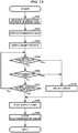
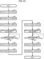
- Step S23 A method for concentrating a cell suspension using the filtering device 120 includes each step described below.
- a cell suspension is moved to the server bag 40 from the culture bag 70 (Step S151).
- the moving step is performed in the cell suspension collecting step described above.
- the rotation control portion 20 judges whether the filtering device support portion 104 is in a first state (Step S152).
- the first state is a state where the axial direction of the body 106 of the filtering device 120 is in parallel with the vertical direction and the inflow port 110 is located downward relative to the first discharge port 111 ( Fig. 7(B) ).
- the rotation control portion 20 drives the rotation mechanism 34 to rotate the filtering device support portion 104 to the first position (Step S153).
- the axial direction of the body 106 of the filtering device 120 does not necessarily need to be in parallel with the vertical direction.
- a priming liquid is supplied to the filtering device 120 supported by the filtering device support portion 104 in the first state.
- the priming liquid is a phosphate buffer or the like, for example.
- the supply/discharge control portion 22 brings the valve V2 connected to the reservoir 116 which is held by the cold storage portion 12 or the normal temperature storage portion 13 and reserves the priming liquid and the valve V8, V13, and V14 into the opened state, and then drives the supply pump 91.
- the priming liquid is supplied to the filtering device 120 through the inflow port 110.
- the air, substances charged for storing the hollow fiber bundle 109, and the like are discharged from the first outflow port 111 of the filtering device 120 in such a manner as to be pressed out by the priming liquid.
- the supply/discharge control portion 22 monitors whether the preset time has passed after the supply pump 91 is driven. As the time, time longer than time enough for the supply pump 91 to discharge the gas from the inside of the filtering device 120 is set. When the supply/discharge control portion 22 judges that the preset time has passed after the supply pump 91 is driven, the supply/discharge control portion 22 stops the supply pump 91, and then brings the valve V2 and the valves V13 and V14 into the closed state. Thus, the priming step is completed.
- the rotation control portion 20 drives the rotation mechanisms 34 to rotate the filtering device support portion 104 by 180° (Step S155).
- the filtering device 120 is brought into a second state.
- the second state is a state where the axial direction of the body 106 of the filtering device 120 is in parallel with the vertical direction and the inflow port 110 is located upward relative to the first discharge port 111.
- the axial direction of the body 106 of the filtering device 120 does not necessarily need to be in parallel with the vertical direction.
- the filtering step (step156) is performed.
- the supply/discharge control portion 22 brings the valves V6 and V12 into the opened state, and then drives the supply pump 91.
- a cell suspension is supplied to the filtering device 120 through the inflow port 110 from the server bag 40.
- the cell suspension supplied to the filtering device 120 flows through the inside of the hollow fiber bundle 109, and then cells contained in the cell suspension precipitate to the downside of the inside of the hollow fiber bundle 109 by gravity to stay near the first outflow port 111.
- a liquid, such as a culture medium, contained in the cell suspension flows out to the outside of the hollow fiber bundle 109 while flowing downward in the internal space of the hollow fiber bundle 109, and then is caused to flow out to the outside of the filtering device 120 through the second outflow port 112.
- the cell suspension which is caused to flow in the filtering device 120 is held in a concentrated state in the hollow fiber bundle 109 and near the first outflow port 111 located downward in the gravity direction.
- the supply/discharge control portion 22 stops the supply pump 91, and then brings the valve V6 and V12 into the closed state.
- the filtering step is completed (Step S156).
- Step S157 The supply/discharge control portion 22 brings the valve V1 connected to the reservoir 117 reserving the fresh culture medium stored in the cold storage portion 12 or the normal temperature storage portion 13 and the valves V14 and V18 into the opened state, and then drives the supply pump 91.
- the fresh culture medium is supplied to the filtering device 120 through the inflow port 110 as illustrated in Fig. 7 (D) .
- the filtering device 120 the fresh culture medium flowing through the hollow fiber bundle 109 is caused to flow out of the filtering device 120 to the collection bag 41 through the first discharge port 111 with the concentrated cell suspension.
- the collecting step is completed (Step S157).
- the concentrated cell suspension is caused to flow in the collection bag 41 but may be caused to flow in the culture bags 70, 80, and 90.
- the inflow and the outflow of a liquid in/from the culture bag 70 or the filtering device 120 are separated into the liquid supply circuit and the liquid discharge circuit, which reduces a possibility that the liquid which is caused to flow out of the culture bag 70 or the filtering device 120 is mixed with the liquid which is caused to flow in the culture bag 70 or the filtering device 120.
- a priming liquid is caused to flow in from the inflow port 110 located downward in the filtering device 120 and gas or the like is discharged from the outflow port 110 located upward in the filtering device 120.
- the cell suspension In the concentration of the cell suspension, the cell suspension is caused to flow in from the inflow port 110 located above the filtering device 120, and then the cell suspension is concentrated by the hollow fiber bundle 109. Then, the concentrated cell suspension is caused to flow out of the first outflow port 110 located downward in the filtering device 120.
- the cell suspension containing the cells cultured in the culture bag 70 can be simply and efficiently concentrated.
- the positions in the vertical direction of the ports 73 and 74 of the culture bag 70 change by the rotation of the first bag holding portion 31 and the like, and therefore the culture bag 70 can be brought into a position suitable for culturing, culture-medium exchange, collection of a cell suspension, and the like.
- the rotation mechanism 34 integrally rotates the first bag holding portion 31 and the filtering device support part 104, and therefore the size of the concentrator 10 is reduced.
- the culture vessel is not limited to a bag-shaped substance and substances having shapes with flexibility, such as a bottle and a cassette, may be used.
- the server bags 39 and 40 and the like are not limited to a bag-shaped substance and substances having shapes with flexibility, such as a bottle and a cassette, may be used.
- the embodiment described above describes the configuration in which the rotation mechanism 34 integrally rotates the first bag holding portion 31 and the filtering device support portion 104 but a configuration may be acceptable in which the first bag holding portion 31 and the filtering device support portion 104 are individually and independently rotated by a separate rotation mechanism (for example, a rotation mechanism and a second rotation mechanism).
- a separate rotation mechanism for example, a rotation mechanism and a second rotation mechanism.
- the embodiment described above describes one having the hollow fiber bunch 109 as the filtering device 120 but a filtering device having a filtration membrane (dialysis membrane) other than hollow fiber bunch 109 may be used.
- the configuration of the culture circuit described in the embodiment described above is merely one example. It is a matter of course that the configuration of the culture circuit may be altered insofar as the scope of the present invention is not altered, e.g., the server bags 39 and 40 and the like are omitted and another vessel and the like are added as appropriate. Moreover, pumps other than the tube pump may be used as the supply pump 91 and the discharge pump 92. Moreover, those other than the valve may be used as the switching mechanism of the flow passages of the culture circuit.
- the embodiment described above describes the example of culturing adhesive cells but cells other than the adhesive cells may be cultured by the culture device 10.
Landscapes
- Engineering & Computer Science (AREA)
- Health & Medical Sciences (AREA)
- Chemical & Material Sciences (AREA)
- Life Sciences & Earth Sciences (AREA)
- Bioinformatics & Cheminformatics (AREA)
- Organic Chemistry (AREA)
- Zoology (AREA)
- Wood Science & Technology (AREA)
- Biomedical Technology (AREA)
- Biotechnology (AREA)
- Genetics & Genomics (AREA)
- General Health & Medical Sciences (AREA)
- Sustainable Development (AREA)
- Microbiology (AREA)
- Biochemistry (AREA)
- General Engineering & Computer Science (AREA)
- Clinical Laboratory Science (AREA)
- Chemical Kinetics & Catalysis (AREA)
- Cell Biology (AREA)
- Virology (AREA)
- Water Supply & Treatment (AREA)
- Analytical Chemistry (AREA)
- Computer Hardware Design (AREA)
- Urology & Nephrology (AREA)
- Medicinal Chemistry (AREA)
- Apparatus Associated With Microorganisms And Enzymes (AREA)
Abstract
Description
- The present invention relates to a concentrator concentrating a cell suspension and a method for concentrating a cell suspension.
- Cell culture includes a process of transferring cells in a culture vessel to another culture vessel and a process of exchanging culture media in a culture vessel. Such processes of the cell culture need to be performed in an aseptic state. The cell culture is performed over several day to several weeks, and, during this period, each process is repeatedly performed. For the purpose of saving labor and culturing a large number of cells in cell culture, a device performing each process in cell culture is known (Patent Document 1).
- For storage or transplantation of cells, for example, the concentration (number of cells per capacity) of cells in a cell suspension containing cultured cells is increased in some cases. As a method for concentrating a cell suspension, a method is known which uses a cell suspension treating device which has a hollow fiber separation membrane and is an inner pressure filtration system (Patent Document 2).
-
- Patent Document 1: Japanese Patent Laid-Open No.
2009-291104 - Patent Document 2: Japanese Patent Laid-Open No.
2012-210187 - A technique using a centrifugal separator as in a cell concentrator described in Patent Document 1 requires a space where a centrifugal separator is placed. Moreover, a space held in an aseptic state for moving a cell suspension from a culture vessel to a vessel suitable for centrifugal separation is required. Furthermore, a robot arm for treating a centrifugal separator requires a complicated motion, which has posed a problem that the device is complicated and the size increases. A cell suspension treating device described in Patent Document 2 is small as compared with the centrifugal separator but is not fully automated, and thus is not suitable for culturing and concentrating a large number of cells.
- The present invention has been made in view of the above-described circumstances. It is an object of the present invention to provide a means capable of simply concentrating a cell suspension.
-
- (1) A concentrator according to the present invention has a filtering device having a case provided with a filtration membrane in the internal space, an inflow port and a first outflow port bringing the inside of the filtration membrane and an outside of the case into communication with each other, and a second outflow port bringing the outside of the filtration membrane and an outside into communication with each other, a liquid supply circuit connected to the inflow port, a liquid discharge circuit connected to the first outflow port and the second outflow port, and a first rotation mechanism rotating the filtering device so that the positions in the vertical direction of the inflow port and the first outflow port are changeable.
The filtering device allows a liquid to flow in through the liquid supply circuit. Moreover, the filtering device allows a liquid to flow out through the liquid discharge circuit. Each of the inflow and the outflow of the liquid in/from the filtering device is performed through a different port and the inflow and the outflow of the liquid in/from the filtering device are separated into the liquid supply circuit and the liquid discharge circuit, which reduces a possibility that a liquid which is caused to flow out of another vessel or device is mixed with a liquid which is caused to flow in the filtering device.
For example, the gravity is utilized in priming of the filtering device or the concentration of a cell suspension using the filtering device. In the priming of the filtering device, a priming liquid is caused to flow in from a port located downward in the filtering device and gas is discharged from a port located upward in the filtering device. In the concentration of the cell suspension, the cell suspension is caused to flow in from the port located upward in the filtering device and cells trapped by the filtration membrane descend downward in the filtering device by gravity.
Since the rotation mechanism rotates the filtering device so that the positions in the vertical direction of the inflow port and the first outflow port of the filtering device are changeable, the positions in the vertical direction of the inflow port and the first outflow port can be changed as appropriate in the priming or the concentration of the cell suspension. This eliminates the necessity of discharging gas and a liquid from the inflow port or causing a liquid to flow in from the first outflow port. Moreover, in the concentration of the cell suspension, cells contained in the cell suspension descend in the internal space of the filtration membrane by the action of the gravity, and thus the entire filtration membrane can be efficiently used. - (2) Preferably, the concentrator further has a culture vessel having a first port and a second port bringing an internal space and the outside into communication with each other, a first reservoir having a third port bringing the internal space and the outside into communication with each other, a collection vessel having a fourth port bringing an internal space and the outside into communication with each other, and a liquid supply/discharge mechanism having a switching mechanism switching flow passages in the liquid supply circuit and the liquid discharge circuit, a first pump circulating a liquid in the liquid supply circuit, and a second pump circulating a fluid in the liquid discharge circuit, in which the liquid supply circuit is connected to the first port, the inflow port, and the third port so that the flow passages are switchable and the liquid discharge circuit is connected to the second port, the first outflow port, the second outflow port, and the fourth port so that the flow passages are switchable.
The culture vessel, the first reservoir, and the filtering device allow a liquid to flow in through the liquid supply circuit. Moreover, the culture vessel and the filtering device allow a liquid to flow out through the liquid discharge circuit. Moreover, the collection vessel allows a liquid to flow in from the filtering device through the liquid discharge circuit. Moreover, each of the inflow and the outflow of a liquid in/from the culture vessel and the filtering device is performed through a different port. Thus, the inflow and the outflow of a liquid in/from each vessel or device are separated into the liquid supply circuit and the liquid discharge circuit, which reduces a possibility that a liquid which is caused to flow out of each vessel or device is mixed with a liquid which is caused to flow in each vessel or device. - (3) Preferably, a second rotation mechanism rotating the culture vessel so that the positions in the vertical direction of the first port and the second port are changeable is further provided.
Thus, the culture vessel can be brought into a position suitable for causing a liquid to flow in the culture vessel or discharging a liquid and gas from the culture vessel. - (4) Preferably, the rotation mechanism rotates the culture vessel so that the positions in the vertical direction of the first port and the second port are changeable and integrally rotates the culture vessel and the filtering device.
Thus, the size of the filtering device is reduced. - (5) Preferably, a second reservoir having a fifth port bringing an internal space and the outside into communication with each other and capable of reserving a priming liquid in the internal space, a third reservoir having a sixth port bringing an internal space and the outside into communication with each other and capable of reserving a culture medium in the internal space, and a control portion controlling an operation of the liquid supply/discharge mechanism and the rotation mechanism are further provided, in which the liquid supply circuit is connected to the fifth port and the sixth port so that the flow passages are switchable, and the control portion executes a moving step of bringing the second port and the third port into communication with each other by the liquid supply/discharge mechanism, and then driving the first pump to thereby move the cell suspension to the first reservoir from the culture vessel, a priming step of bringing the filtering device into a first state in which the inflow port is located downward relative to the first outflow port by the rotation mechanism, bringing the fifth port and the inflow port into communication with each other by the liquid supply/discharge mechanism and opening the inflow port, and then driving at least the first pump to thereby supply the priming liquid to the filtering device from the second reservoir, a filtering step of bringing the filtering device into a second state in which the inflow port is located upward relative to the first outflow port by the rotation mechanism, bringing the third port and the inflow port into communication with each other by the liquid supply/discharge mechanism, closing the first outflow port and opening the second outflow port, and then driving at least the first pump to thereby supply the cell suspension to the filtering device from the first reservoir, and a collecting step of bringing the sixth port and the inflow port into communication with each other by the liquid supply/discharge mechanism, closing the second outflow port and bringing the first outflow port and the fourth port into communication with each other, and then driving at least the first pump to thereby supply the cell suspension to the collection vessel from the filtering device.
By the moving step, the cell suspension is caused to flow in the first reservoir from the culture vessel. By the priming step, the priming liquid is supplied to the inflow port of the filtering device from the second reservoir. In the priming step, the inflow port is located downward relative to the first outflow port in the filtering device, and therefore gas present inside the filtering device is discharged from the first outflow port. By the filtering step, the cell suspension is supplied to the inflow port of the filtering device from the first reservoir. In the filtering step, the inflow port is located upward relative to the first outflow port in the filtering device, and therefore the cells contained in the cell suspension descend to stay near the first outflow port in the filtering device. By the collecting step, the culture medium is caused to flow in the inflow port of the filtering device from the third reservoir, and then the cells staying inside the filtering device flow in the collection vessel with the culture medium from the first outflow port. - (6) Preferably, the control portion brings the culture vessel into a third state in which the first port is located downward relative to the second port by the rotation mechanism or the second rotation mechanism in the moving step.
Due to the fact that the first port is located downward relative to the second port of the culture vessel in the moving step, the cell suspension is easily caused to flow out of the internal space of the culture vessel. - (7) Preferably, the culture vessel has a bag shape in which an internal space is formed with a flexible sheet.
- (8) Preferably, an inner surface demarcating the internal space in the culture bag has cell adhesiveness suitable for culturing adhesive cells.
- (9) Preferably, the filtration membrane contains hollow fibers.
- (10) Preferably, the first pump and the second pump are tube pumps.
- (11) A method for concentrating a cell suspension according to the present invention uses a switching mechanism of switching flow passages in a liquid supply circuit connected to a first port bringing the internal space of a culture vessel and the outside into communication with each other, an inflow port bringing an inside of a filtration membrane of a filtering device having a case provided with the filtration membrane in the internal space and an outside of the case into communication with each other, a third port bringing an internal space of a first reservoir and the outside into communication with each other, a fifth port bringing an internal space of a second reservoir capable of reserving a priming liquid in the internal space and the outside into communication with each other, and a sixth port bringing an internal space of a third reservoir capable of reserving a culture medium in the internal space and the outside into communication with each other so that the flow passages are switchable and in a liquid discharge circuit connected to a second port bringing the internal space of the culture vessel and the outside into communication with each other, a first outflow port bringing the inside of the filtration membrane of the filtering device and the outside of the case into communication with each other, a second outflow port bringing the outside of the filtration membrane of the filtering device and the outside into communication with each other, and a fourth port bringing an internal space of the collection vessel and the outside into communication with each other so that the flow passages are switchable, a liquid supply/discharge mechanism having a first pump circulating a liquid in the liquid supply circuit and a second pump circulating a liquid in the liquid discharge circuit, and a rotation mechanism rotating the filtering device so that the positions in the vertical direction of the inflow port and the first outflow port are changeable, and the method includes a moving step of bringing the second port and the third port into communication with each other, and then driving the first pump to thereby move a cell suspension to the first reservoir from the culture vessel, a priming step of bringing the filtering device into a first state in which the inflow port is located downward relative to the first outflow port, bringing the fifth port and the inflow port into communication with each other and opening the inflow port, and then driving at least the first pump drive to thereby supply a priming liquid to the filtering device from the second reservoir, a filtering step of bringing the filtering device into a second state in which the inflow port is located upward relative to the first outflow port, bringing the third port and the inflow port into communication with each other, closing the first outflow port and opening the second outflow port open, and then driving at least the first pump to thereby supply the cell suspension to the filtering device from the first reservoir, and a collecting step of bringing the sixth port and the inflow port into communication with each other, closing the second outflow port and bringing the first outflow port and the fourth port into communication with each other, and then driving at least the first pump to thereby supply the cell suspension to the collection vessel from the filtering device.
- According to the present invention, a cell suspension containing cells cultured in a culture vessel can be simply and efficiently concentrated.
-
- [
Fig. 1] Fig. 1 is a schematic view of aconcentrator 10. - [
Fig. 2] Fig. 2 is a perspective diagram of the inside of aculture portion 14, in whichtubes 38 are omitted and acontrol portion 11 is illustrated for explanation. - [
Fig. 3] Fig. 3 is a schematic view viewed from above the inside of theculture portion 14, in which holdingplates 42 on the upper surface of a firstbag holding portion 31, a secondbag holding portion 32, and a thirdbag holding portion 33 are omitted. - [
Fig. 4] Fig. 4 is an exploded perspective view of the thirdbag holding portion 33. - [
Fig. 5] Figs. 5(A) to 5(C) are cross-sectional views illustrating a cut plane V-V of aculture bag 70. - [
Fig. 6] Fig. 6 is a schematic view of the firstbag holding portion 31 for explaining afiltering device 120. - [
Fig. 7] Figs. 7(A) to 7(D) are schematic views of thefiltering device 120. - [
Fig. 8] Fig. 8 is a perspective diagram of aweight detector 23 and abearing portion 24. - [
Fig. 9] Fig. 9(A) is a perspective diagram of atube 99 andFig. 9(B) is a schematic view of a cross section along a cut plane IX-IX of thetube 99. - [
Fig. 10] Fig. 10 is an enlarged cross-sectional view illustrating a cut plane V-V of theculture bag 70. - [
Fig. 11] Fig. 11 is a flow chart of a cell culture method. - [
Fig. 12] Fig. 12 is a schematic view for explaining a first position of the firstbag holding portion 31. - [
Fig. 13] Fig. 13 is a flow chart of a liquid supply step. - [
Fig. 14] Fig. 14 is a schematic view for explaining a third position of the firstbag holding portion 31. - [
Fig. 15] Fig. 15 is a cross-sectional view illustrating the cut plane V-V of theculture bag 70 when the firstbag holding portion 31 is in the third position. - [
Fig. 16] Fig. 16 is a flow chart of a culture step. - [
Fig. 17] Fig. 17 (A) is a cross-sectional view illustrating the cut plane V-V of theculture bag 70 when the firstbag holding portion 31 is in the first position andFig. 17(B) is a cross-sectional view illustrating the cut plane V-V of theculture bag 70 when the firstbag holding portion 31 is in a fourth position. - [
Fig. 18] Fig. 18 is a schematic view for explaining the fourth position of the firstbag holding portion 31. - [
Fig. 19] Fig. 19 is a flow chart of a culture medium exchanging step. - [
Fig. 20] Fig. 20 is a schematic view for explaining a second position of the firstbag holding portion 31. - [
Fig. 21] Fig. 21 is a cross-sectional view illustrating the cut plane V-V of theculture bag 70 when the firstbag holding portion 31 is in the second position. - [
Fig. 22] Fig. 22 is a flow chart of a liquid discharging step. - [
Fig. 23] Fig. 23 is a flow chart of a cell suspension collecting step. - [
Fig. 24] Fig. 24 is a schematic view for explaining the firstbag holding portion 31 in a reverse third position. - [
Fig. 25] Fig. 25 is a cross-sectional view illustrating the cut plane V-V of theculture bag 70 when the firstbag holding portion 31 is in the reverse third position. - [
Fig. 26] Fig. 26 is a flow chart of a cell suspension concentrating step. - Hereinafter, a preferable embodiment of the present invention is described. It is a matter of course that this embodiment is merely one embodiment of the present invention and the embodiment can be altered in the range where the scope of the present invention is not altered.
- As illustrated in
Fig. 1 , aconcentrator 10 has acontrol portion 11, acold storage portion 12, a normaltemperature storage portion 13, and twoculture portions 14. Thecold storage portion 12 and the normaltemperature storage portion 13 are provided outside theculture portion 14. The twoculture portions 14 are separately disposed upward and downward. Thecontrol portion 11 has adisplay 15. Thedisplay 15 is disposed on the front surface of theconcentrator 10. Thecontrol portion 11 has a data input portion (not illustrated), and various conditions about cell culture and the like are input into thecontrol portion 11 through the data input portion. - The
concentrator 10 is a device automatically culturing cells according to a program input and stored in thecontrol portion 11. Hereinafter, constituent components of theconcentrator 10 are described in detail. In the following description, avertical direction 101 is defined along the upper and lower sides inFig. 1 , alateral direction 102 is defined along the right and left sides inFig. 1 , and a forward andbackward direction 103 is defined along a direction (direction perpendicular to the sheet surface ofFig. 1 ) perpendicular to thevertical direction 101 and thelateral direction 102. - As illustrated in
Figs. 2 and3 , thecontrol portion 11 has arotation control portion 20, aculture control portion 21, and a supply/discharge control portion 22. Therotation control portion 20, theculture control portion 21, and the supply/discharge control portion 22 are arithmetic units for controlling an operation of a control target of each of the portions and store a program and information beforehand. Theculture control portion 21 outputs control information to therotation control portion 20 and the supply/discharge control portion 22. Moreover, theculture control portion 21 outputs control information for controlling the environmental temperature of theculture portions 14. Therotation control portion 20 is electrically connected to therotation mechanisms 34 and outputs the control information for controlling the drive of therotation mechanisms 34. The supply/discharge control portion 22 is connected to a liquid supply/discharge mechanism 37 and outputs control information for driving actuators of the liquid supply/discharge mechanism 37, i.e., asupply pump 91, adischarge pump 92, and valves V1 to V18. - As illustrated in
Fig. 1 , thecold storage portion 12 is a case in which shelfs for placing vessels reserving a reagent or a culture medium therein are formed. On the front surface of thecold storage portion 12, a door capable of opening and closing an opening provided in the front surface of the case is provided. Thecold storage portion 12 is a so-called refrigerator having a cooling mechanism (not illustrated). The temperature inside thecold storage portion 12 is kept at an arbitrary preset temperature, e.g., about 10°C or about 4°C, for example, lower than normal temperature by the cooling mechanism. The normaltemperature storage portion 13 is a case having shelfs for placing vessels reserving a reagent or a culture medium therein. - The vessels placed inside the
cold storage portion 12 and the normaltemperature storage portion 13 can reserve a reagent or a culture medium in a fluid tight manner. Examples of the vessels include a bag, a bottle, a cassette, and the like, for example. To each vessel, a tube and the like are connected so that a liquid therein can flow out, and thus a reserved liquid can be caused to flow out by the liquid supply/discharge mechanism 37. - The two
culture portions 14 have the same structure except a difference in the arrangement in the device, and therefore a detailed configuration thereof is described below taking oneculture portion 14 as an example. Theculture portion 14 is space formed inside theconcentrator 10. The space is partitioned by a case frame of theconcentrator 10 and a tray 17 (Fig. 2 ). Thetray 17 can be drawn to the front side from the front surface of theconcentrator 10. By drawing of thetray 17, theculture portion 14 is opened, so that each configuration provided in theculture portion 14 can be accessed. - The
culture portion 14 can be held at predetermined temperature and CO2 concentration. Although not illustrated in each figure, theculture portion 14 is provided with a warming device and a CO2 supply device. Moreover, theculture portion 14 is provided with a temperature sensor and a CO2 concentration sensor. Theculture control portion 21 drives the warming device and the CO2 supply device in order to set the inside of theculture portion 14 to set temperature and CO2 concentration based on outputs of the temperature sensor and the CO2 concentration sensor. In cell culture, theculture portion 14 can be held in an environment of 37°C and 5%CO2, for example. - As illustrated in
Figs. 2 and3 , the firstbag holding portion 31, the secondbag holding portion 32, and the thirdbag holding portion 33 are provided side by side in thelateral direction 102 in thetray 17. Therotation mechanism 34 is provided in the rear side in the forward andbackward direction 103 of the firstbag holding portion 31. By therotation mechanism 34, the firstbag holding portion 31 is rotated to a predetermined rotation position. Similarly, therotation mechanism 34 is provided in the rear side in the forward andbackward direction 103 of the secondbag holding portion 32 and therotation mechanism 34 is provided in the rear side in the forward andbackward direction 103 of the thirdbag holding portion 33. The liquid supply/discharge mechanism 37 is provided on the front side of thetray 17. Moreover, a filteringdevice support portion 104 connected to the firstbag holding portion 31 in such a manner as to be coaxially rotatable with the firstbag holding portion 31 is provided. Moreover,vessel storage portions lateral direction 102 of thetray 17 and avessel storage portion 29 is provided on the right side in thelateral direction 102 of thetray 17. - The first
bag holding portion 31, the secondbag holding portion 32, and the thirdbag holding portion 33 basically have the same configuration except a difference in the arrangement and the size, and therefore a detailed configuration is described taking the thirdbag holding portion 33 as an example. The outer shapes and the sizes of the firstbag holding portion 31, the secondbag holding portion 32, and the thirdbag holding portion 33 are designed according to the outer shape of a culture bag which can be held. - As illustrated in
Fig. 4 andFig. 5 , the thirdbag holding portion 33 has holdingplates holders spacers rotating shafts plates plates culture portion 14 to theculture bag 90 sandwiched between the holdingplates plates plates surfaces - On the
spacer 47, adistance sensor 67 is disposed. On the holdingplate 42 abutting on thespacer 47, amagnet 68 is disposed facing thedistance sensor 67. Thedistance sensor 67 outputs a voltage according to the magnetic flux density from themagnet 68, and a hall element is used, for example. When the holdingplates plate 42 and thespacer 47 is constant, and therefore an output of thedistance sensor 67 is also constant. When the holdingplates plates plate 42 and thespacer 47, the magnetic flux density of themagnet 68 which thedistance sensor 67 detects decreases, and the output of thedistance sensor 67 varies. - The
control portion 11 stores a threshold value beforehand. The threshold value is a value for judging that the distance between the holdingplate 42 and thespacer 47 increases to reach a fixed value or above. Thecontrol portion 11 can judge that the distance between the holdingplate 42 and thespacer 47 increases to reach a fixed value or above by comparing an output of thedistance sensor 67 with the threshold value. Thedistance sensor 67 may be provided in thespacer 46 instead of thespacer 47 or may be provided in both thespacers magnet 68 may be provided in either the holdingplate distance sensor 67. The arrangements of thedistance sensor 67 and themagnet 68 are relative. It is a matter of course that the arrangement of thedistance sensor 67 and the arrangement of themagnet 68 may be switched. Thedistance sensor 67 and themagnet 68 may be disposed facing each other in the holdingplates - The
spacers plates ports spacers plates spacers spacers plates spacers spacers portions portions tubes 99 of theculture bag 90 each are inserted. Thespacers plates - The
holders plates spacers holders plates spacers plates holders spacers holders screws 18 is projected to the inside of the lateral U-shape of theholders holders holders screws 18, theholders plates spacers surfaces plates holders plates plates holders - The
holders rotating shafts plates shafts holders plates rotating shafts surfaces plates - As illustrated in
Fig. 5(A) , in the case where a liquid is not contained in theculture bag 90 supported by the thirdbag holding portion 33 when the thirdbag holding portion 33 is in a state where the supportingsurface 66 is located downward relative to the supportingsurface 65 and the supportingsurfaces culture bag 90 mainly contacts the supportingsurface 66. Herein, the distance between the supportingsurfaces Fig. 5(B) , even when it is supposed that theculture bag 90 expands by a reserved liquid to contact the supportingsurfaces plates culture bag 90. Such a liquid amount is set as the amount of a liquid which can be reserved in theculture bag 90 beforehand. As illustrated inFig. 5(C) , when a liquid with an amount larger than the preset amount is caused to flow in theculture bag 90, theculture bag 90 in contact with the supportingsurfaces plates plates surfaces distance sensor 67 according to the distance between the holdingplate 42 and thespacer 47 exceeds the threshold value described above, thecontrol portion 11 judges that the distance between the supportingsurfaces - Detailed configurations of the first
bag holding portion 31 and the secondbag holding portion 32 are not described in detail with reference to the drawings but have holding plate holders and spacers as with the thirdbag holding portion 33. - As illustrated in
Fig. 6 , a filteringdevice support portion 104 is disposed in the rear side in the forward andbackward direction 103 of the firstbag holding portion 31. The filteringdevice support portion 104 is integrally connected to the firstbag holding portion 31. Therefore, the filteringdevice support portion 104 rotates integrally with the firstbag holding portion 31 around the rotatingshafts device support portion 104 supports afiltering device 120. Thefiltering device 120 supported by the filteringdevice support portion 104 is disposed so that aninflow port 110 and afirst outflow port 111 each face a direction crossing (in this embodiment, direction orthogonal to) the rotation axis by the rotatingshafts filtering device 120 rotates around the rotatingshafts device support portion 104, the positions in thevertical direction 101 of theinflow port 110 and thefirst outflow port 111 are changed. A direction where each of theinflow port 110 and thefirst outflow port 111 of thefiltering device 120 supported by the filteringdevice support portion 104 extends and a direction where each of theports culture bag 70 held by the firstbag holding portion 31 extends are in agreement with each other. - As illustrated in
Fig. 2 ,openings 17A are formed in three places in thetray 17 in the portions where the firstbag holding portion 31, the secondbag holding portion 32, the thirdbag holding portion 33, and the filteringdevice support portion 104 are disposed in order to avoid interference with the firstbag holding portion 31, the secondbag holding portion 32, the thirdbag holding portion 33, and the filteringdevice support portion 104 which are rotating. - In the front side and the rear side in the forward and
backward direction 103 of eachopening 17A, a pair of bearingportions 24 is individually disposed. The pair of bearingportions 24 rotatably supports each of therotating shafts bag holding portion 31, the secondbag holding portion 32, the thirdbag holding portion 33, and the filteringdevice support portion 104 in the state in parallel with the forward andbackward direction 103. Thus, each of the holdingplates bag holding portion 31, the secondbag holding portion 32, and the thirdbag holding portion 33 and the filteringdevice support portion 104 can be rotated around the rotatingshafts - As illustrated in
Fig. 8 , each bearingportion 24 is placed on eachweight detector 23 provided on thetray 17. By a pair ofweight detectors 23 corresponding to each of the firstbag holding portion 31, the secondbag holding portion 32, or the thirdbag holding portion 33, the weights of the corresponding bag holding portion, a culture bag held by the corresponding bag holding portion, the bearingportion 24, and the like are detected. As theweight detector 23, a load cell converting power (weight) applied to theweight detector 23 to an electric signal or the like is used, for example. - As illustrated in
Fig. 2 andFig. 3 , therotation mechanism 34 is provided in the rear side in the forward andbackward direction 103 of each bearingportion 24 in thetray 17. Therotation mechanism 34 has a rotationshaft support portion 16 and a stepping motor (not illustrated). The rotationshaft support portion 16 extends toward the rear side in the forward andbackward direction 103 and is coaxially connected to therotating shaft 49 supported by each bearingportion 24. Although not illustrated in each figure, power is supplied to the stepping motor from a power supply. Moreover, drive is transmitted to the stepping motor and the rotationshaft support portion 16 by a known speed reduction gear or the like. By the supply of power based on a control signal output from therotation control portion 20 to the stepping motor, the rotationshaft support portion 16 rotates by only a predetermined rotation angle. The stepping motor may be provided with a sensor for detecting the original point position, i.e., the rotation position where the supportingsurfaces plates bag holding portion 31, the secondbag holding portion 32, and the thirdbag holding portion 33 are in parallel with the horizontal direction. Therotation control portion 20 can drive the stepping motor so that the supportingsurfaces inflow port 110 and thefirst outflow port 111 of thefiltering device 120 extend in the horizontal direction. The stepping motor is an example of a driving source of therotation mechanism 34 and the other driving sources, such as a DC motor having an encoder capable of detecting the rotation amount, may be used, for example, in replace of the stepping motor. The rotation position of the driving source may be detected by other detection means, such as a resolver, or a sensor capable of directly detecting the rotation position of the firstbag holding portion 31 and the like may be provided. - As illustrated in
Figs. 2 and3 , the liquid supply/discharge mechanism 37 has asupply pump 91, adischarge pump 92, and a plurality of valves V1 to V18. As thesupply pump 91 and thedischarge pump 92, known substances capable of sending a liquid in a tube are used. Examples of such a pump include a so-called tube pump sending liquid by squeezing an elastic tube with a turning roller, for example. Power is supplied to thesupply pump 91 and thedischarge pump 92 from the power supply. The supply/discharge control portion 22 can drive thesupply pump 91 and thedischarge pump 92 for a definite period of time by controlling the power supplied to thesupply pump 91 and thedischarge pump 92. - The plurality of valves V1 to V18 are roughly classified into the valves V1 to V11 relating to the
supply pump 91 and the valves V12 to V18 relating to thedischarge pump 92. Thesupply pump 91 and the valves V1 to V11 are aliquid supply mechanism 81 in the liquid supply/discharge mechanism 37 and thedischarge pump 92 and the valves V12 to V18 are a liquid discharge mechanism 82 in the liquid supply/discharge mechanism 37. In each valve V1 to V18, ON/OFF is switched based on a control signal output from the supply/discharge control portion 22. By ON/OFF of each valve V1 to V18, the flow of a liquid in eachtube 38 connected to the culture bag and the like can be changed. The valves V1 to V18 are examples of the switching mechanism. As the valves V1 to V18, an electromagnetic valve is used, for example. - As illustrated in
Fig. 3 , a culture circuit has threeculture bags server bags 39 and 40 (one example of the first reservoir), a collection bag 41 (one example of the collection vessel), thefiltering device 120,reservoirs 116 and 117 (one example of the second reservoir and the third reservoir) held by thecold storage portion 12 or the normaltemperature storage portion 13, and a plurality oftubes 38 connecting them so that a liquid can flow. Theculture bag 70 is disposed in the firstbag holding portion 31. Theculture bag 80 is disposed in the secondbag holding portion 32. Theculture bag 90 is disposed in the thirdbag holding portion 33. Thefiltering device 120 is disposed in the filteringdevice support portion 104. Thecollection bag 41 is disposed in theculture portion 14. Theculture bags culture bag 70 is smaller than that of theculture bags culture bag 90 as an example. - As illustrated in
Fig. 4 , theculture bag 90 is formed into a bag shape by bonding peripheral edges of two rectangular sheets formed of a synthetic resin by known methods, such as thermal welding. Thetubes 99 formed of a synthetic resin are disposed near the center of each of a pair ofend portions internal space 75 of theculture bag 90 of eachtube 99, anotch portion 105 is formed towardedges internal space 75 of theculture bag 90 as illustrated inFigs. 9(A) and 9(B) . Thenotch portion 105 is located in a portion not facinginner surfaces internal space 75 of theculture bag 90, i.e., a place facing end portions other than the pair ofend portions Fig. 10 . Even when it is supposed that, when a liquid is caused to flow out of theculture bag 90, theinner surfaces internal space 75, theinner surfaces tubes 99 due to the fact that thetubes 99 are present between theinner surfaces notch portion 105 is formed in a place not facing theinner surfaces tubes 99, a liquid remaining near theedges internal space 75 can flow in the internal space of thetubes 99 through thenotch portions 105. - As illustrated in
Fig. 4 , theinternal space 75 of theculture bag 90 is brought into communication with the outside through the internal space of thetubes 99. More specifically, theports tubes 99. Theedges tubes 99 are disposed of the edges demarcating theinternal space 75 of theculture bag 90 have a tapered shape in which the distance between theedges ports edges culture bag 90 toward the center where thetubes 99 are disposed. In the state where theculture bag 90 is held by the firstbag holding portion 31, thetubes 99 extend in a direction orthogonal to therotating shafts ports rotating shafts - The synthetic resin sheet for use in the
culture bag 90 has flexibility and has bending rigidity with which the bag shape can be maintained when a culture medium is placed therein. For example, low density polyethylene, ultrahigh molecular weight polyethylene, cyclic polyolefin resin, and those having a laminated structure with the materials above or other materials are mentioned. - The
inner surfaces culture bag 90 have cell adhesiveness suitable for culturing adhesive cells. In detail, cell adhesive functional groups are exposed by plasma treatment or the like, for example, in theinner surfaces - The
server bags collection bag 41, and thereservoirs Fig. 3 are formed into a bag shape by bonding synthetic resin sheets and have at least one ofports 94 to 98 (one example of the third port, the fourth port, the fifth port, and the sixth port). Theserver bags collection bag 41 collects a cell suspension. Thereservoirs server bags collection bag 41, and thereservoirs - As illustrated in
Fig. 3 ,tubes 38 are individually connected to each port of theculture bags server bags collection bag 41, and thereservoirs tube 38 connected to oneport 73 of each of theculture bags tube 38 connected to theinflow port 110 of thefiltering device 120, eachtube 38 connected to each of theports server bags tube 38 connected to each of theports reservoirs supply pump 91. Thesetubes 38 are integrated into onetube 38 through a connector before reaching thesupply pump 91 to configure a liquid supply circuit. Moreover, thetubes 38 each are passed through the valves V6 to V11 before integrated into onetube 38 and the valves V6 to V11 can change the internal space of eachtube 38 to an opened state where a liquid can flow and a closed state where a liquid cannot flow. - Each
tube 38 connected to theother port 74 of each of theculture bags tube 38 connected to thefirst outflow port 111 and asecond outflow port 112 of thefiltering device 120, and thetube 38 connected to theport 96 of thecollection bag 41 are extended to thedischarge pump 92. Thesetubes 38 are integrated into onetube 38 before reaching thedischarge pump 92 through a connector to configure a liquid discharge circuit. Moreover, thetubes 38 each are passed through the valves V12 and V14 to V18 before integrated into onetube 38 and the valves V12 and V14 to V18 can change the internal space of eachtube 38 to an opened state where a liquid can flow and a closed state where a liquid cannot flow. - The
tube 38 leading to thesupply pump 91 is branched again, and then eachtube 38 is connected to bags and vessels placed in thecold storage portion 12 or the normaltemperature storage portion 13 through the valves V1 to V5. These bags and the vessels reserve a cell suspension, a culture medium, a peeling liquid, and the like. Thetube 38 leading to thedischarge pump 92 is connected to awaste liquid vessel 19. - As illustrated in
Fig. 7(A) , thefiltering device 120 has a body 106 (one example of the case), acap 107, acap 108, and a hollow fiber bundle 109 (one example of the filtration membrane). Thebody 106 has an approximately cylindrical shape. Thebody 106 is opened in both sides in the axial direction (direction along the vertical direction inFig. 7 (A) ). Thecap 107 and thecap 108 are screwed into each opening of thebody 106. In thecap 107, theinflow port 110 bringing the internal space and the external space of thefiltering device 120 into communication with each other is formed so as to extend along the axial direction of thebody 106. In thecap 108, thefirst outflow port 111 bringing the internal space and the external space of thefiltering device 120 into communication with each other is formed so as to extend along the axial direction of thebody 106. - A pair of hollow fiber supports (not illustrated) is formed near each opening of the
body 106. Thehollow fiber bundle 109 is supported by the pair of hollow fiber supports to be disposed in the internal space of thebody 106. Both ends of thehollow fiber bundle 109 are disposed near the openings of thebody 106. The hollow fiber supports support both the ends of thehollow fiber bundle 109 and separates both the ends of thehollow fiber bundle 109 and the internal space of thebody 106 in a fluid tight manner. Therefore, a liquid flowing into the internal space of thebody 106 through theinflow port 110 of thecap 107 flows into one end of a hollow fiber bundle 114 and does not flow in the space demarcated by the pair of hollow fiber supports in the internal space of thebody 106. On the other hand, a liquid flowing out of the other end of thehollow fiber bundle 109 flows out of thefirst outflow port 111 of thecap 108 to the outside and a liquid does not flow in thefirst outflow port 111 from the space demarcated by the pair of hollow fiber supports in the internal space of thebody 106. - In the
body 106, thesecond outflow port 112 extends in a direction orthogonal to the axial direction (direction along the vertical direction inFig. 7 ) of thebody 106 on the side where thecap 108 is screwed and theport 113 extends in a direction orthogonal to the axial direction of thebody 106 on the side where thecap 107 is screwed. Thesecond outflow port 112 and theport 113 bring the space demarcated by the pair of hollow fiber supports in the internal space of thebody 106 and the outside of thebody 106 into communication with each other. A liquid flowing out of thehollow fiber bundle 109 by filtering is caused to flow out to the outside through thesecond discharge port 112. Theport 113 is sealed in this embodiment. Thetubes 38 described above are connected to theinflow port 110, thefirst outflow port 111, and thesecond outflow port 112. - The
hollow fiber bundle 109 is a bundle of hollow fibers in which a dialysis membrane is formed into a tubular shape. The hollow fibers each are opened in both ends thereof. Examples of raw materials of the hollow fibers include triacetate, polyether sulfone, and the like. The thickness, film thickness, pore size, length, type, and the like of the hollow fibers are set as appropriate according to the conditions, such as a size, of cells to be filtered in thefiltering device 120. - Hereinafter, a cell culture method using the
concentrator 10 is described. The cell culture using theconcentrator 10 can be performed by arbitrarily selecting any one or a plurality of theculture bags culture bag 70 is described. The cell culture method using theconcentrator 10 includes each step described below. - (1) Culture step of amplifying cells in the
culture bag 70. - (2) Culture medium exchanging step of exchanging culture media in the
culture bag 70. - (3) Cell suspension collecting step of collecting a cell suspension in the
culture bag 70. - (4) Cell suspension concentrating step of concentrating a cell suspension in the
server bag 40. - In the
concentrator 10, a culture circuit is set beforehand. In detail, as illustrated inFig. 3 , theculture bags bag holding portion 31, the secondbag holding portion 32, and the thirdbag holding portion 33, respectively, thefiltering device 120 is set in the filteringdevice support portion 104, theserver bags vessel storage portions collection bag 41 is held by thevessel storage portion 29. Thereservoirs cold storage portion 12 or the normaltemperature storage portion 13. Thetubes 38 of the circuit are set in the valves V1 to V18, thesupply pump 91, and thedischarge pump 92. - A user sets beforehand the
culture control portion 21 so that the culture step , the culture medium exchanging step, the culture step , the cell suspension concentrating step, and the cell suspension collecting step are successively performed. A user also sets beforehand various settings, such as the culture time in the culture step, the culture medium exchange amount in the culture medium exchanging step, the concentration time and the culture medium supply amount in the cell suspension concentrating step, and the reaction time with a peeling liquid in the cell suspension collecting step. Theculture control portion 21 outputs a first information containing various setting information in the culture step, outputs a second information containing various setting information in the culture medium exchanging step, and outputs a third information containing various setting information in the cell suspension collecting step. Theculture control portion 21 outputs various setting information in the cell suspension concentrating step. Therotation control portion 20 controls the drive of therotation mechanism 34 based on each information output from theculture control portion 21. The supply/discharge control portion 22 controls the drive of the liquid supply/discharge mechanism 37 (liquid supply mechanism 81 and liquid discharge mechanism 82) based on each information output from theculture control portion 21. - As illustrated in
Fig. 11 , theculture portion 14 in theconcentrator 10 performs a preliminary operation due to the fact that theculture control portion 21 receives an input of start of culture. In detail, due to the fact that the warming device and the CO2 supply device are driven based on the control information from theculture control portion 21, the temperature of theculture portion 14 is adjusted to 37°C and the carbon dioxide concentration is adjusted to 5% (Step S11). Subsequently, therotation control portion 20 judges whether the firstbag holding portion 31 is in the first position (Step S12). When therotation control portion 20 judges that the firstbag holding portion 31 is not in the first position, i.e., the stepping motor in therotation mechanism 34 is not located at the original point position (Step S12: No), therotation control portion 20 rotates the stepping motor of therotation mechanism 34 until the stepping motor reaches the original point position. Thus, as illustrated inFig. 12 , the firstbag holding portion 31 stops at the first position in which the supportingsurfaces bag holding portion 31 is in the first position (Step S12: Yes), therotation control portion 20 does not drive therotation mechanism 34. The supporting surfaces 65 and 66 in the first position may be almost in parallel with the horizontal direction and do not need to be strictly in parallel with the horizontal direction. The valves V1 to V18 bring thetubes 38 into the closed state. - Subsequently, the supply/
discharge control portion 22 supplies a cell suspension to the culture bag 70 (Step S14). The supply of the cell suspension to theculture bag 70 is performed according to the liquid supply step. In detail, as illustrated inFig. 13 , when the firstbag holding portion 31 stops at the first position, theweight detector 23 detects the weight of theculture bag 70 and the firstbag holding portion 31. According to information on the weight output from theweight detector 23, thecontrol portion 11 sets a first reference value (Step S121). Subsequently, thecontrol portion 11 calculates a value obtained by adding the weight of a cell suspension to be supplied to theculture bag 70 to the first reference value as a first target value. The weight of a liquid to be supplied to theculture bag 70 can be calculated based on the capacity of a cell suspension to be supplied to theculture bag 70. Assuming that the specific gravity of various liquids, such as a cell suspension, a culture medium, and a peeling liquid, is approximately 1, it may be regarded that the capacity (mL) and the weight (g) are equal. In Step S14, the cell suspension is supplied to theculture bag 70 but Step S14 may be omitted and a cell suspension may be manually charged into theculture bag 70 beforehand. - When the first
bag holding portion 31 is in the first position, the supply/discharge control portion 22 drives theliquid supply mechanism 81 to supply a liquid to theculture bag 70. In detail, the valves V6 and V9 are brought into the opened state (Step S122). Then, thesupply pump 91 is driven (Step S123). Theserver bag 40 reserves beforehand a cell suspension containing cells to be cultured. Therefore, the cell suspension is supplied from theserver bag 40 to theculture bag 70 through theport 73. While the cell suspension is being supplied to theculture bag 70, i.e., while thesupply pump 91 is being driven, thecontrol portion 11 monitors whether an output value of thedistance sensor 67 exceeds a preset threshold value (Step 124). When thecontrol portion 11 judges that an output value of thedistance sensor 67 exceeds the threshold value (Step 124: Yes), thecontrol portion 11 issues an alarm by generating a buzzer sound or turning on a light (Step S126). Then, the supply/discharge control portion 22 stops the supply pump 91 (Step S128). - The
control portion 11 monitors whether preset time has passed after thesupply pump 91 is driven (Step 125). As the time, time longer than time enough for thesupply pump 91 to supply a maximum amount of liquid to theculture bag 70 is set. When thecontrol portion 11 judges that the preset time has passed after thesupply pump 91 is driven (Step 125: Yes), thecontrol portion 11 issues an alarm in the same manner as above (Step S126), and then the supply/discharge control portion 22 stops the supply pump 91 (Step 128). - The
control portion 11 monitors whether an output value of theweight detector 23 has reached the first target value while thesupply pump 91 is being driven (Step 127). When thecontrol portion 11 judges that the output value of theweight detector 23 has reached the first target value (Step 127: Yes), the supply/discharge control portion 22 stops the supply pump 91 (Step S128) to bring the valves V6 and V9 into the closed state (Step S129). Thus, the supply (liquid supply step) of the cell suspension to theculture bag 70 is completed (Step S14). - Subsequently, as illustrated in
Fig. 11 , therotation control portion 20 drives therotation mechanism 34 to rotate the firstbag holding portion 31 counterclockwise by 90°. Thus, as illustrated inFigs. 14 and15 , the firstbag holding portion 31 is brought into a third position where the supportingsurfaces port 74 is located upward, and theport 73 is located downward (Step S15). To theedge 88 of theport 74 located upward in theculture bag 70 held by the firstbag holding portion 31 in the third position, gas entering theinternal space 75 gathers. Since theedge 88 has the tapered shape toward theport 74, the gas moving along theedge 88 gathers to theport 74. The supporting surfaces 65 and 66 in the third position may be in parallel with the approximately vertical direction and do not necessarily need to be strictly in parallel with the vertical direction. - The first
bag holding portion 31 is brought into the third position, and then the supply/discharge control portion 22 brings the valves V6 and V9 into the closed state and brings the valves V13 and V15 into the opened state. Subsequently, the supply/discharge control portion 22 drives thedischarge pump 92. Thus, a liquid or gas is discharged from theport 74 of theculture bag 70. When the gas remains in theinternal space 75 of theculture bag 70 when a cell suspension is supplied to theculture bag 70, the gas is discharged from theinternal space 75 through the port 74 (Step S16). Thus, a preliminary operation is completed. - After the preliminary operation is completed, the
culture control portion 21 successively performs the culture step (Step S17), the culture medium exchanging step (Step S18), the culture step (Step S19), and the cell suspension collecting step (Step S20). The details of each step are described later. When a direction of performing subculture is input into theculture control portion 21 after the cell suspension collecting step (Step S21: Yes), a cell suspension collected by theother culture bags culture control portion 21 does not perform subculture. Thereafter, a cell suspension concentrating step (Step S23) is performed. - Hereinafter, the culture step is described. When the culture step is performed, the
culture control portion 21 outputs the first information to therotation control portion 20 and the supply/discharge control portion 22. As illustrated inFig. 12 andFig. 16 , therotation control portion 20 drives therotation mechanism 34 to bring the firstbag holding portion 31 into the first position (Step S24). Thus, as illustrated inFig. 17(A) , theinner surface 71 is located upward and theinner surface 72 is located downward in theculture bag 70. Theinternal space 75 of theculture bag 70 reserves a cell suspension containing cells to be cultured and a culture medium. In theinternal space 75, the cells descend in the cell suspension by gravity to contact theinner surface 72. Thus, the cells adhere to theinner surface 72 to be cultured. - As illustrated in
Fig. 16 , therotation control portion 20 maintains the firstbag holding portion 31 in the first position until the preset time passes (Step S25: No). After the preset time has passed (Step S25: Yes), therotation control portion 20 drives therotation mechanism 34 to rotate the firstbag holding portion 31 clockwise by 180° as viewed from the front of the concentrator 10 (Step S26). Thus, as illustrated inFig. 17 (B) andFig. 18 , the firstbag holding portion 31 is brought into a fourth position in which the supportingsurfaces inner surface 72 of theculture bag 70 is located upward, and theinner surface 71 is located downward. When theinner surface 72 is located upward and theinner surfaces 71 is located downward in theculture bag 70, cells contained in the cell suspension reserved in theinternal space 75 of theculture bag 70 and not adhering to theinner surface 72 descend in the cell suspension by gravity to contact theinner surface 71. Thus, the cells adhere to theinner surface 71 to be cultured. Therotation control portion 20 maintains the firstbag holding portion 31 in the fourth position until the preset time passes (Step S27: No). When the preset time has passed, the culture step is completed (Step S27: Yes). - Hereinafter, the culture medium exchanging step is described. When the culture medium exchanging step is performed, the
culture control portion 21 outputs the second information to therotation control portion 20 and the supply/discharge control portion 22. The valve V1 and the valve V7 through which thetubes 38, which are connected to thereservoir 117 reserving a fresh culture medium stored in thecold storage portion 12 or the normaltemperature storage portion 13, are passed are brought into the opened state, and then thesupply pump 91 is driven to supply the fresh culture medium to theserver bag 39. Thereafter, the supply/discharge control portion 22 stops thesupply pump 91, brings the valve V1 into the closed state, and then brings the valve V6 into the opened state. The supply/discharge control portion 22 brings the valves V6 and V7 through which thetubes 38, which are connected to theserver bags supply pump 91 to supply a fresh culture medium to theserver bag 40. Thereafter, the supply/discharge control portion 22 stops thesupply pump 91, and then brings the valves V6 and V7 into the closed state. The fresh culture medium is held in theserver bag 40 to be warmed to 37°C. - As illustrated in
Fig. 19 , therotation control portion 20 drives therotation mechanism 34 to rotate the firstbag holding portion 31 in the first position clockwise by 30° as viewed from the front of theconcentrator 10. Thus, as illustrated inFigs. 20 and21 , the firstbag holding portion 31 is brought into the second position in which the acute angle formed by the supportingsurfaces port 73 is located upward and theport 74 is located downward (Step S31). In the second position, the acute angle formed by the supportingsurfaces surfaces surfaces - Subsequently, the supply/
discharge control portion 22 discharges the culture medium from the culture bag 70 (Step S32). The discharge of the culture medium from theculture bag 70 is performed according to the liquid supply step. In detail, when the firstbag holding portion 31 stops at the second position as illustrated inFig. 22 , theweight detector 23 detects the weights of theculture bag 70 and the firstbag holding portion 31. According to information on the weight output from theweight detector 23, thecontrol portion 11 sets a second reference value (Step S141). Subsequently, thecontrol portion 11 calculates a value obtained by subtracting the weight of a culture medium to be discharged from theculture bag 70 from the second reference value as a second target value. - When the first
bag holding portion 31 stops at the second position, the supply/discharge control portion 22 drives the liquid discharge mechanism 82 to discharge the culture medium from theculture bag 70. When described in detail, the valves V13 and V15 are brought into the opened state (Step S142). Subsequently, thedischarge pump 92 is driven (Step S143). Thecontrol portion 11 monitors whether the preset time has passed after thedischarge pump 92 is driven (Step S144). As the time, time longer than time enough for thedischarge pump 92 to discharge the half amount of a liquid from theculture bag 70 is set. When thecontrol portion 11 judges that the preset time has passed after thedischarge pump 92 is driven (Step 144: Yes), thecontrol portion 11 issues an alarm in the same manner as above (Step S145), and then the supply/discharge control portion 22 stops the discharge pump 92 (Step 147). - The
control portion 11 monitors whether the output value of theweight detector 23 has reached the second target value while thedischarge pump 92 is being driven (Step 146). When thecontrol portion 11 judges that the output value of theweight detector 23 has reached the second target value (Step 146: Yes), the supply/discharge control portion 22 stops the discharge pump 92 (Step S147) and brings the valves V13 and V15 into the closed state (Step S148). Thus, the half of the culture medium reserved in theculture bag 70 is discharged from theinternal space 75 of the culture bag 70 (Liquid discharging step) (Step S32). Due to the fact that the firstbag holding portion 31 is maintained at the second position, the discharge of the culture medium from theport 74 is facilitated. Even when the half of the culture medium is discharged from theculture bag 70, theinner surfaces culture bag 70 are difficult to contact each other as illustrated inFig. 21 . - As illustrated in
Fig. 19 , after the half culture medium is discharged from theculture bag 70, therotation control portion 20 drives therotation mechanisms 34 to bring the firstbag holding portion 31 into the first position (Step S33). After the firstbag holding portion 31 is brought into the first position, the valve V6 and V9 are brought into the opened state, and then the supply of the culture medium to theculture bag 70 is performed in the same manner as in the liquid supply step described above. Thus, the fresh culture medium reserved in theserver bag 40 is supplied to the culture bag 70 (Step S34). The amount of the fresh culture medium to be supplied to theculture bag 70 is the same as the amount of the culture medium previously discharged from theculture bag 70, i.e., the half amount of the culture medium reserved in theinternal space 75. After the fresh culture medium is supplied to theculture bag 70, the supply/discharge control portion 22 stops thesupply pump 91, and then brings the valve V6 and V9 into the closed state. - After the fresh culture medium is supplied to the
culture bag 70, therotation control portion 20 drives therotation mechanism 34 to rotate the firstbag holding portion 31 in the first position counterclockwise by 90° as viewed from the front of theconcentrator 10. Thus, as illustrated inFig. 14 , the firstbag holding portion 31 is brought into the third position in which the supportingsurfaces port 73 is located downward, and theport 74 is located upward (Step S35). After the firstbag holding portion 31 is brought into the third position, the supply/discharge control portion 22 brings the valves V13 and V15 into the opened state, and then drives thedischarge pump 92. Thus, even when gas is mixed in theinternal space 75 of theculture bag 70, the gas is discharged from theinternal space 75 with the culture medium through the port 74 (Step S36). Then, thedischarge pump 92 is stopped, and then the valves V13 and V15 are brought into the closed state, so that the culture medium exchanging step (Step S18) is completed. - When the culture medium exchanging step (Step S18) is completed, the culture step (Step S19) is performed in the same manner as above. The culture medium exchanging step and the culture step may be further repeated after subculture. When the amount of the cells increases in the culture step repeated after subculture, the cell suspension may be moved to the
culture bags culture bag 70 so that theculture bags culture bag 70 are used. After the culture step (Step S19) repeatedly performed as necessary, the cell suspension collecting step (Step S20) and the cell suspension concentrating step (Step S23) are performed. - Hereinafter, the cell suspension collecting step is described. When the cell suspension collecting step is performed, the
culture control portion 21 outputs the third information to therotation control portion 20 and the supply/discharge control portion 22. - As illustrated in
Fig. 23 , therotation control portion 20 drives therotation mechanism 34 to rotate the firstbag holding portion 31 in the fourth position counterclockwise by 90° as viewed from the front of theconcentrator 10. Thus, as illustrated inFig. 24 andFig. 25 , the firstbag holding portion 31 is brought into the third position in which the supportingsurfaces port 73 is located upward, and theport 74 is located downward (Step S41). In this embodiment, any position is referred to as the third position insofar as the supportingsurfaces bag holding portion 31 are in parallel with the vertical direction irrespective of the positions (upward or downward) of theports - As illustrated in
Fig. 23 , after the firstbag holding portion 31 is brought into the third position, the culture medium is discharged from theculture bag 70. The supply/discharge control portion 22 brings the valve V13 and V15 into the opened state, and then drives thedischarge pump 92. Thus, the entire amount of the culture medium reserved in theculture bag 70 is discharged from theinternal space 75 through the port 74 (Step S42). After the entire amount of the culture medium is discharged from theculture bag 70, therotation control portion 20 drives therotation mechanism 34 to bring the firstbag holding portion 31 in the third position into the first position (Step S43). - After the first
bag holding portion 31 is brought into the first position, a peeling liquid is supplied to theculture bag 70. The supply/discharge control portion 22 brings any one of the valves V3 to V5 through which thetube 38, which is connected to a vessel reserving a peeling liquid stored in thecold storage portion 12 or the normaltemperature storage portion 13, is passed and the valve V9 into the opened state, and then drives thesupply pump 91. Thus, the peeling liquid is supplied to theinternal space 75 of theculture bag 70 through the port 73 (Step S44). After the peeling liquid is supplied to theculture bag 70, the supply/discharge control portion 22 stops thesupply pump 91, and then brings any one of the valves V3 to V5 and V9, which are brought into the opened state, into the closed state. Therotation control portion 20 maintains the firstbag holding portion 31 in the first position until the preset time passes (Step S45: No). The peeling liquid weakens the adhesion to theinner surfaces culture bag 70 of the cells adhering to theinner surfaces inner surfaces inner surfaces bag holding portion 31, and the like as appropriate. After the peeling liquid is supplied to theculture bag 70, gas may be discharged from theinternal space 75 of theculture bag 70 as necessary in the same manner as above. - After the preset time has passed (Step S45: Yes), the
rotation control portion 20 drives therotation mechanism 34 to rotate the firstbag holding portion 31 counterclockwise by 90° as viewed from the front of theconcentrator 10 to bring the same into the third position (Step S46). After the firstbag holding portion 31 is brought into the third position, the discharge of the cell suspension from theculture bag 70 is performed in the same manner as in the liquid discharging step described above. The supply/discharge control portion 22 brings the valves V6 and V9 into the opened state, and then reversely drives thesupply pump 91. Thus, the peeling liquid is discharged from theinternal space 75 through theport 73 in theculture bag 70 to the waste liquid vessel 19 (Step S47). After the entire amount of the peeling liquid is discharged from theculture bag 70, therotation control portion 20 drives therotation mechanism 34 to rotate the firstbag holding portion 31 clockwise by 90° as viewed from the front of theconcentrator 10 to bring the same into the first position (Step S48). - After the first
bag holding portion 31 is brought into the first position, a culture medium is supplied to theculture bag 70. The supply/discharge control portion 22 brings any one of the valves V3 to V5 through which thetube 38, which is connected to a vessel reserving the culture medium stored in thecold storage portion 12 or the normaltemperature storage portion 13, is passed and the valve V9 into the opened state, and then drives thesupply pump 91. Thus, the culture medium is supplied to theinternal space 75 of theculture bag 70 through the port 73 (Step S49). After the culture medium is supplied to theculture bag 70, the supply/discharge control portion 22 stops thesupply pump 91, and then brings any one of the valves V3 to V5 and V9, which are brought into the opened state, into the closed state. Therotation control portion 20 maintains the firstbag holding portion 31 in the first position until the preset time passes (Step S50). By the supply of the culture medium, the cells adhering to theinner surfaces culture bag 70 are peeled off. The peeling of the cells from theinner surfaces bag holding portion 31, the period of time when it is allowed to stand, and the like as appropriate. After the culture medium is supplied to theculture bag 70, gas may be discharged from theinternal space 75 of theculture bag 70 as necessary in the same manner as above. - After the preset time has passed (Step S50), the
rotation control portion 20 drives therotation mechanism 34 to rotate the firstbag holding portion 31 counterclockwise by 90° as viewed from the front of theconcentrator 10 to bring the same into the third position (Step S51). After the firstbag holding portion 31 is brought into the third position, the discharge of a cell suspension from theculture bag 70 is performed in the same manner as in the liquid discharging step described above. The supply/discharge control portion 22 brings the valves V6 and V9 into the opened state, and then reversely drives thesupply pump 91. Thus, the cell suspension is discharged from theinternal space 75 through the port 73 (Step S52) in theculture bag 70 to be collected by theserver bag 40. Thus, the cell suspension collecting step (Step S20) is completed. - Hereinafter, the cell suspension concentrating step (Step S23) is described. A method for concentrating a cell suspension using the
filtering device 120 includes each step described below. - (4-1) Moving step of moving a cell suspension to the
server bag 40 from theculture bag 70. - (4-2) Priming step of supplying a priming liquid to the
filtering device 120. - (4-3) Filtering step of supplying a cell suspension to the
filtering device 120. - (4-4) Collecting step of collecting a cell suspension from the
filtering device 120. - As illustrated in
Fig. 26 , a cell suspension is moved to theserver bag 40 from the culture bag 70 (Step S151). The moving step is performed in the cell suspension collecting step described above. - Subsequently, the
rotation control portion 20 judges whether the filteringdevice support portion 104 is in a first state (Step S152). The first state is a state where the axial direction of thebody 106 of thefiltering device 120 is in parallel with the vertical direction and theinflow port 110 is located downward relative to the first discharge port 111 (Fig. 7(B) ). When the filteringdevice support portion 104 is not in the first state (Step S152: No), therotation control portion 20 drives therotation mechanism 34 to rotate the filteringdevice support portion 104 to the first position (Step S153). In the first state, the axial direction of thebody 106 of thefiltering device 120 does not necessarily need to be in parallel with the vertical direction. - Then, priming (Step S154) is performed. As illustrated in
Fig. 7(B) , a priming liquid is supplied to thefiltering device 120 supported by the filteringdevice support portion 104 in the first state. The priming liquid is a phosphate buffer or the like, for example. The supply/discharge control portion 22 brings the valve V2 connected to thereservoir 116 which is held by thecold storage portion 12 or the normaltemperature storage portion 13 and reserves the priming liquid and the valve V8, V13, and V14 into the opened state, and then drives thesupply pump 91. Thus, the priming liquid is supplied to thefiltering device 120 through theinflow port 110. The air, substances charged for storing thehollow fiber bundle 109, and the like are discharged from thefirst outflow port 111 of thefiltering device 120 in such a manner as to be pressed out by the priming liquid. The supply/discharge control portion 22 monitors whether the preset time has passed after thesupply pump 91 is driven. As the time, time longer than time enough for thesupply pump 91 to discharge the gas from the inside of thefiltering device 120 is set. When the supply/discharge control portion 22 judges that the preset time has passed after thesupply pump 91 is driven, the supply/discharge control portion 22 stops thesupply pump 91, and then brings the valve V2 and the valves V13 and V14 into the closed state. Thus, the priming step is completed. - After the priming step is completed, the
rotation control portion 20 drives therotation mechanisms 34 to rotate the filteringdevice support portion 104 by 180° (Step S155). Thus, as illustrated inFig. 7(C) , thefiltering device 120 is brought into a second state. The second state is a state where the axial direction of thebody 106 of thefiltering device 120 is in parallel with the vertical direction and theinflow port 110 is located upward relative to thefirst discharge port 111. In the second state, the axial direction of thebody 106 of thefiltering device 120 does not necessarily need to be in parallel with the vertical direction. - Subsequently, the filtering step (step156) is performed. The supply/
discharge control portion 22 brings the valves V6 and V12 into the opened state, and then drives thesupply pump 91. Thus, a cell suspension is supplied to thefiltering device 120 through theinflow port 110 from theserver bag 40. The cell suspension supplied to thefiltering device 120 flows through the inside of thehollow fiber bundle 109, and then cells contained in the cell suspension precipitate to the downside of the inside of thehollow fiber bundle 109 by gravity to stay near thefirst outflow port 111. On the other hand, a liquid, such as a culture medium, contained in the cell suspension flows out to the outside of thehollow fiber bundle 109 while flowing downward in the internal space of thehollow fiber bundle 109, and then is caused to flow out to the outside of thefiltering device 120 through thesecond outflow port 112. Thus, the cell suspension which is caused to flow in thefiltering device 120 is held in a concentrated state in thehollow fiber bundle 109 and near thefirst outflow port 111 located downward in the gravity direction. After the entire amount of the cell suspension is supplied to thefiltering device 120, the supply/discharge control portion 22 stops thesupply pump 91, and then brings the valve V6 and V12 into the closed state. Thus, the filtering step is completed (Step S156). - Subsequently, the collecting step (Step S157) is performed. The supply/
discharge control portion 22 brings the valve V1 connected to thereservoir 117 reserving the fresh culture medium stored in thecold storage portion 12 or the normaltemperature storage portion 13 and the valves V14 and V18 into the opened state, and then drives thesupply pump 91. Thus, the fresh culture medium is supplied to thefiltering device 120 through theinflow port 110 as illustrated inFig. 7 (D) . In thefiltering device 120, the fresh culture medium flowing through thehollow fiber bundle 109 is caused to flow out of thefiltering device 120 to thecollection bag 41 through thefirst discharge port 111 with the concentrated cell suspension. Thus, the collecting step is completed (Step S157). The concentrated cell suspension is caused to flow in thecollection bag 41 but may be caused to flow in theculture bags - According to this embodiment, the inflow and the outflow of a liquid in/from the
culture bag 70 or thefiltering device 120 are separated into the liquid supply circuit and the liquid discharge circuit, which reduces a possibility that the liquid which is caused to flow out of theculture bag 70 or thefiltering device 120 is mixed with the liquid which is caused to flow in theculture bag 70 or thefiltering device 120. On the other hand, in the priming of thefiltering device 120, a priming liquid is caused to flow in from theinflow port 110 located downward in thefiltering device 120 and gas or the like is discharged from theoutflow port 110 located upward in thefiltering device 120. In the concentration of the cell suspension, the cell suspension is caused to flow in from theinflow port 110 located above thefiltering device 120, and then the cell suspension is concentrated by thehollow fiber bundle 109. Then, the concentrated cell suspension is caused to flow out of thefirst outflow port 110 located downward in thefiltering device 120. Thus, the cell suspension containing the cells cultured in theculture bag 70 can be simply and efficiently concentrated. - Moreover, the positions in the vertical direction of the
ports culture bag 70 change by the rotation of the firstbag holding portion 31 and the like, and therefore theculture bag 70 can be brought into a position suitable for culturing, culture-medium exchange, collection of a cell suspension, and the like. - Moreover, the
rotation mechanism 34 integrally rotates the firstbag holding portion 31 and the filteringdevice support part 104, and therefore the size of theconcentrator 10 is reduced. - Although the embodiment described above describes the
culture bags server bags - Moreover, the embodiment described above describes the configuration in which the
rotation mechanism 34 integrally rotates the firstbag holding portion 31 and the filteringdevice support portion 104 but a configuration may be acceptable in which the firstbag holding portion 31 and the filteringdevice support portion 104 are individually and independently rotated by a separate rotation mechanism (for example, a rotation mechanism and a second rotation mechanism). - Moreover, the embodiment described above describes one having the
hollow fiber bunch 109 as thefiltering device 120 but a filtering device having a filtration membrane (dialysis membrane) other thanhollow fiber bunch 109 may be used. - Moreover, the configuration of the culture circuit described in the embodiment described above is merely one example. It is a matter of course that the configuration of the culture circuit may be altered insofar as the scope of the present invention is not altered, e.g., the
server bags supply pump 91 and thedischarge pump 92. Moreover, those other than the valve may be used as the switching mechanism of the flow passages of the culture circuit. - The embodiment described above describes the example of culturing adhesive cells but cells other than the adhesive cells may be cultured by the
culture device 10. -
- 10
- Concentrator
- 11
- Control portion
- 22
- Supply/discharge control portion
- 31, 32, 33
- Bag holding portion
- 34
- Rotation mechanism
- 37
- Liquid supply/discharge mechanism
- 38
- Tube
- 40
- Server bag
- 41
- Collection bag
- 48, 49
- Rotation shaft
- 70, 80, 90
- Culture bag
- 73, 74
- Port
- 91
- Supply pump
- 92
- Discharge pump
- 95 to 98
- Port
- 106
- Body
- 109
- Hollow fiber bundle
- 110
- Inflow port
- 111
- First outflow port
- 112
- Second outflow port
- 116, 117
- Reservoir
- 120
- Filtering device
- V1 to V18
- Valve
Claims (11)
- A concentrator comprising:a filtering device having a case provided with a filtration membrane in an internal space, an inflow port and a first outflow port bringing an inside of the filtration membrane and an outside of the case into communication with each other, and a second outflow port bringing an outside of the filtration membrane and an outside into communication with each other;a liquid supply circuit connected to the inflow port;a liquid discharge circuit connected to the first outflow port and the second outflow port; anda first rotation mechanism rotating the filtering device so that positions in a vertical direction of the inflow port and the first outflow port are changeable.
- The concentrator according to Claim 1 further comprising:a culture vessel having a first port and a second port bringing an internal space and an outside into communication with each other;a first reservoir having a third port bringing an internal space and the outside into communication with each other;a collection vessel having a fourth port bringing an internal space and the outside into communication with each other; anda liquid supply/discharge mechanism having a switching mechanism switching flow passages in the liquid supply circuit and the liquid discharge circuit, a first pump circulating a liquid in the liquid supply circuit, and a second pump circulating a fluid in the liquid discharge circuit, whereinthe liquid supply circuit is connected to the first port, the inflow port, and the third port so that the flow passages are switchable, andthe liquid discharge circuit is connected to the second port, the first outflow port, the second outflow port, and the fourth port so that the flow passages are switchable.
- The concentrator according to Claim 2 further comprising:a second rotation mechanism rotating the culture vessel so that positions in a vertical direction of the first port and the second port are changeable.
- The concentrator according to Claim 2, wherein
the first rotation mechanism rotates the culture vessel so that the positions in the vertical direction of the first port and the second port are changeable and integrally rotates the culture vessel and the filtering device. - The concentrator according to any one of Claims 2 to 4 further comprising:a second reservoir having a fifth port bringing an internal space and the outside into communication with each other and capable of reserving a priming liquid in the internal space;a third reservoir having a sixth port bringing an internal space and the outside into communication with each other and capable of reserving a culture medium in the internal space; anda control portion controlling an operation of the liquid supply/discharge mechanism and the first rotation mechanism, whereinthe liquid supply circuit is connected to the fifth port and the sixth port so that flow passages are switchable, andthe control portion executesa moving step of bringing the second port and the third port into communication with each other by the liquid supply/discharge mechanism, and then driving the first pump to thereby move the cell suspension to the first reservoir from the culture vessel,a priming step of bringing the filtering device into a first state in which the inflow port is located downward relative to the first outflow port by the rotation mechanism, bringing the fifth port and the inflow port into communication with each other by the liquid supply/discharge mechanism and opening the inflow port, and then driving at least the first pump to thereby supply the priming liquid to the filtering device from the second reservoir,a filtering step of bringing the filtering device into a second state in which the inflow port is located upward relative to the first outflow port by the rotation mechanism, bringing the third port and the inflow port into communication with each other by the liquid supply/discharge mechanism, closing the first outflow port and opening the second outflow port, and then driving at least the first pump to thereby supply the cell suspension to the filtering device from the first reservoir, anda collecting step of bringing the sixth port and the inflow port into communication with each other by the liquid supply/discharge mechanism, closing the second outflow port and bringing the first outflow port and the fourth port into communication with each other, and then driving at least the first pump to thereby supply the cell suspension to the collection vessel from the filtering device.
- The concentrator according to Claim 5, wherein
the control portion brings the culture vessel into a third state in which the first port is located downward relative to the second port by the first rotation mechanism or the second rotation mechanism in the moving step. - The concentrator according to any one of Claims 2 to 6, wherein
the culture vessel has a bag shape in which an internal space is formed with a flexible sheet. - The concentrator according to Claim 7, wherein
an inner surface demarcating the internal space in the culture bag has cell adhesiveness suitable for culturing adhesive cells. - The concentrator according to any one of Claims 1 to 8, wherein
the filtration membrane contains hollow fibers. - The concentrator according to any one of Claims 2 to 8, wherein
the first pump and the second pump are tube pumps. - A method for concentrating a cell suspension using a switching mechanism of switching flow passages in a liquid supply circuit connected to a first port bringing an internal space of a culture vessel and an outside into communication with each other, an inflow port bringing an inside of a filtration membrane of a filtering device having a case provided with the filtration membrane in an internal space and an outside of the case into communication with each other, a third port bringing an internal space of a first reservoir and the outside into communication with each other, a fifth port bringing an internal space of a second reservoir capable of reserving a priming liquid in the internal space and the outside into communication with each other, and a sixth port bringing an internal space of a third reservoir capable of reserving a culture medium in the internal space and the outside into communication with each other so that the flow passages are switchable and in a liquid discharge circuit connected to a second port bringing the internal space of the culture vessel and the outside into communication with each other, a first outflow port bringing the inside of the filtration membrane of the filtering device and the outside of the case into communication with each other, a second outflow port bringing the outside of the filtration membrane of the filtering device and the outside into communication with each other, and a fourth port bringing an internal space of a collection vessel and the outside into communication with each other so that the flow passages are switchable, a liquid supply/discharge mechanism having a first pump circulating a liquid in the liquid supply circuit and a second pump circulating a liquid in the liquid discharge circuit, and a first rotation mechanism rotating the filtering device so that positions in a vertical direction of the inflow port and the first outflow port are changeable, the method comprising:a moving step of bringing the second port and the third port into communication with each other, and then driving the first pump to thereby move a cell suspension to the first reservoir from the culture vessel;a priming step of bringing the filtering device into a first state in which the inflow port is located downward relative to the first outflow port, bringing the fifth port and the inflow port into communication with each other and opening the inflow port, and then driving at least the first pump drive to thereby supply a priming liquid to the filtering device from the second reservoir;a filtering step of bringing the filtering device into a second state in which the inflow port is located upward relative to the first outflow port, bringing the third port and the inflow port into communication with each other, closing the first outflow port and opening the second outflow port open, and then driving at least the first pump to thereby supply the cell suspension to the filtering device from the first reservoir; anda collecting step of bringing the sixth port and the inflow port into communication with each other, closing the second outflow port and bringing the first outflow port and the fourth port into communication with each other, and then driving at least the first pump to thereby supply the cell suspension to the collection vessel from the filtering device.
Applications Claiming Priority (2)
| Application Number | Priority Date | Filing Date | Title |
|---|---|---|---|
| JP2015105863 | 2015-05-25 | ||
| PCT/JP2016/065331 WO2016190313A1 (en) | 2015-05-25 | 2016-05-24 | Concentrating device and method for concentrating cell suspension |
Publications (3)
| Publication Number | Publication Date |
|---|---|
| EP3305887A1 true EP3305887A1 (en) | 2018-04-11 |
| EP3305887A4 EP3305887A4 (en) | 2019-02-20 |
| EP3305887B1 EP3305887B1 (en) | 2021-04-07 |
Family
ID=57392858
Family Applications (1)
| Application Number | Title | Priority Date | Filing Date |
|---|---|---|---|
| EP16800018.0A Active EP3305887B1 (en) | 2015-05-25 | 2016-05-24 | Concentrating device and method for concentrating cell suspension |
Country Status (4)
| Country | Link |
|---|---|
| US (1) | US10793822B2 (en) |
| EP (1) | EP3305887B1 (en) |
| JP (1) | JP6828681B2 (en) |
| WO (1) | WO2016190313A1 (en) |
Families Citing this family (4)
| Publication number | Priority date | Publication date | Assignee | Title |
|---|---|---|---|---|
| US10975345B2 (en) * | 2015-05-25 | 2021-04-13 | Nipro Corporation | Culturing device |
| JP6677248B2 (en) * | 2015-05-25 | 2020-04-08 | ニプロ株式会社 | Culture device |
| MX2021003469A (en) * | 2018-09-27 | 2021-06-18 | Dainippon Ink & Chemicals | Degasification system, liquid degasification method, degasification module, method for manufacturing degasification system, and method for producing natural resources. |
| JP7379824B2 (en) * | 2019-02-12 | 2023-11-15 | 東洋製罐グループホールディングス株式会社 | Liquid thickness control mechanism, culture device, and liquid thickness control method |
Family Cites Families (8)
| Publication number | Priority date | Publication date | Assignee | Title |
|---|---|---|---|---|
| JP2005169181A (en) * | 2003-12-08 | 2005-06-30 | Kurita Water Ind Ltd | Vertical membrane separator and maintenance method for vertical membrane separator |
| JP2005323534A (en) * | 2004-05-13 | 2005-11-24 | Onecell Inc | Membrane for separating and recovering cell and method for separating and recovering cell |
| JP2012210187A (en) * | 2011-03-31 | 2012-11-01 | Kaneka Corp | Method for condensing cell suspension |
| EP2639294B1 (en) | 2012-03-15 | 2026-06-24 | CellProthera | Automaton and automated method for cell culture |
| WO2014119529A1 (en) * | 2013-01-29 | 2014-08-07 | 株式会社カネカ | Method for removing erythrocytes |
| CN105408467A (en) | 2013-07-23 | 2016-03-16 | 株式会社钟化 | Method for producing cell concentrate, and cell suspension treatment system |
| JP6469123B2 (en) * | 2014-10-16 | 2019-02-13 | 旭化成メディカル株式会社 | Hollow fiber membrane type body fluid filtration device, operation method and filtration method of hollow fiber membrane type body fluid filtration device |
| EP3394242A2 (en) * | 2015-12-22 | 2018-10-31 | Corning Incorporated | Cell separation device and method for using same |
-
2016
- 2016-05-24 EP EP16800018.0A patent/EP3305887B1/en active Active
- 2016-05-24 JP JP2017520720A patent/JP6828681B2/en active Active
- 2016-05-24 WO PCT/JP2016/065331 patent/WO2016190313A1/en not_active Ceased
- 2016-05-24 US US15/574,530 patent/US10793822B2/en active Active
Also Published As
| Publication number | Publication date |
|---|---|
| JPWO2016190313A1 (en) | 2018-03-15 |
| EP3305887A4 (en) | 2019-02-20 |
| EP3305887B1 (en) | 2021-04-07 |
| JP6828681B2 (en) | 2021-02-10 |
| US10793822B2 (en) | 2020-10-06 |
| US20180148680A1 (en) | 2018-05-31 |
| WO2016190313A1 (en) | 2016-12-01 |
Similar Documents
| Publication | Publication Date | Title |
|---|---|---|
| EP3305885A1 (en) | Culturing device | |
| EP3305886A1 (en) | Culturing device | |
| EP3305887B1 (en) | Concentrating device and method for concentrating cell suspension | |
| CN109715230B (en) | Blood component sampling box, blood sampling loop kit and blood component sampling system | |
| JP6466841B2 (en) | Cell input / distribution method in bioreactor of cell proliferation system | |
| CA2780722C (en) | Automated apparatus and method of cell culture | |
| CA2679097C (en) | Disposable tubing set for use with a cell expansion apparatus and method for sterile sampling | |
| RU2013145505A (en) | MEMBRANE SEPARATION DEVICES, SYSTEMS AND METHODS USING THE INDICATED DEVICES AND SYSTEMS AND METHODS OF DATA MANAGEMENT | |
| JP2018183150A (en) | Method of concentrating component of fluid circulated through cell growth chamber | |
| US11318464B2 (en) | Automated machine for sorting of biological fluids | |
| US20240287439A1 (en) | Systems and methods for manufacturing cells | |
| JP2021000007A (en) | Cell recovery method and cell culture apparatus | |
| US20240360399A1 (en) | Methods To Remove Solutes Without Suspension Cell Loss | |
| TH151963A (en) | The runaway filter and cell sorting system are the same. |
Legal Events
| Date | Code | Title | Description |
|---|---|---|---|
| STAA | Information on the status of an ep patent application or granted ep patent |
Free format text: STATUS: THE INTERNATIONAL PUBLICATION HAS BEEN MADE |
|
| PUAI | Public reference made under article 153(3) epc to a published international application that has entered the european phase |
Free format text: ORIGINAL CODE: 0009012 |
|
| STAA | Information on the status of an ep patent application or granted ep patent |
Free format text: STATUS: REQUEST FOR EXAMINATION WAS MADE |
|
| 17P | Request for examination filed |
Effective date: 20171221 |
|
| AK | Designated contracting states |
Kind code of ref document: A1 Designated state(s): AL AT BE BG CH CY CZ DE DK EE ES FI FR GB GR HR HU IE IS IT LI LT LU LV MC MK MT NL NO PL PT RO RS SE SI SK SM TR |
|
| AX | Request for extension of the european patent |
Extension state: BA ME |
|
| DAV | Request for validation of the european patent (deleted) | ||
| DAX | Request for extension of the european patent (deleted) | ||
| A4 | Supplementary search report drawn up and despatched |
Effective date: 20190123 |
|
| RIC1 | Information provided on ipc code assigned before grant |
Ipc: C12M 3/06 20060101AFI20190117BHEP Ipc: B01D 61/00 20060101ALI20190117BHEP Ipc: C12M 1/10 20060101ALI20190117BHEP Ipc: B01D 63/16 20060101ALI20190117BHEP Ipc: B01D 63/02 20060101ALI20190117BHEP Ipc: C12M 3/02 20060101ALI20190117BHEP Ipc: C12M 3/04 20060101ALI20190117BHEP |
|
| GRAP | Despatch of communication of intention to grant a patent |
Free format text: ORIGINAL CODE: EPIDOSNIGR1 |
|
| STAA | Information on the status of an ep patent application or granted ep patent |
Free format text: STATUS: GRANT OF PATENT IS INTENDED |
|
| INTG | Intention to grant announced |
Effective date: 20201126 |
|
| GRAS | Grant fee paid |
Free format text: ORIGINAL CODE: EPIDOSNIGR3 |
|
| GRAA | (expected) grant |
Free format text: ORIGINAL CODE: 0009210 |
|
| STAA | Information on the status of an ep patent application or granted ep patent |
Free format text: STATUS: THE PATENT HAS BEEN GRANTED |
|
| AK | Designated contracting states |
Kind code of ref document: B1 Designated state(s): AL AT BE BG CH CY CZ DE DK EE ES FI FR GB GR HR HU IE IS IT LI LT LU LV MC MK MT NL NO PL PT RO RS SE SI SK SM TR |
|
| REG | Reference to a national code |
Ref country code: GB Ref legal event code: FG4D |
|
| REG | Reference to a national code |
Ref country code: AT Ref legal event code: REF Ref document number: 1379709 Country of ref document: AT Kind code of ref document: T Effective date: 20210415 Ref country code: CH Ref legal event code: EP |
|
| REG | Reference to a national code |
Ref country code: DE Ref legal event code: R096 Ref document number: 602016055733 Country of ref document: DE |
|
| REG | Reference to a national code |
Ref country code: IE Ref legal event code: FG4D |
|
| REG | Reference to a national code |
Ref country code: LT Ref legal event code: MG9D |
|
| REG | Reference to a national code |
Ref country code: NL Ref legal event code: MP Effective date: 20210407 Ref country code: AT Ref legal event code: MK05 Ref document number: 1379709 Country of ref document: AT Kind code of ref document: T Effective date: 20210407 |
|
| PG25 | Lapsed in a contracting state [announced via postgrant information from national office to epo] |
Ref country code: HR Free format text: LAPSE BECAUSE OF FAILURE TO SUBMIT A TRANSLATION OF THE DESCRIPTION OR TO PAY THE FEE WITHIN THE PRESCRIBED TIME-LIMIT Effective date: 20210407 Ref country code: AT Free format text: LAPSE BECAUSE OF FAILURE TO SUBMIT A TRANSLATION OF THE DESCRIPTION OR TO PAY THE FEE WITHIN THE PRESCRIBED TIME-LIMIT Effective date: 20210407 Ref country code: BG Free format text: LAPSE BECAUSE OF FAILURE TO SUBMIT A TRANSLATION OF THE DESCRIPTION OR TO PAY THE FEE WITHIN THE PRESCRIBED TIME-LIMIT Effective date: 20210707 Ref country code: NL Free format text: LAPSE BECAUSE OF FAILURE TO SUBMIT A TRANSLATION OF THE DESCRIPTION OR TO PAY THE FEE WITHIN THE PRESCRIBED TIME-LIMIT Effective date: 20210407 Ref country code: LT Free format text: LAPSE BECAUSE OF FAILURE TO SUBMIT A TRANSLATION OF THE DESCRIPTION OR TO PAY THE FEE WITHIN THE PRESCRIBED TIME-LIMIT Effective date: 20210407 Ref country code: FI Free format text: LAPSE BECAUSE OF FAILURE TO SUBMIT A TRANSLATION OF THE DESCRIPTION OR TO PAY THE FEE WITHIN THE PRESCRIBED TIME-LIMIT Effective date: 20210407 |
|
| PG25 | Lapsed in a contracting state [announced via postgrant information from national office to epo] |
Ref country code: RS Free format text: LAPSE BECAUSE OF FAILURE TO SUBMIT A TRANSLATION OF THE DESCRIPTION OR TO PAY THE FEE WITHIN THE PRESCRIBED TIME-LIMIT Effective date: 20210407 Ref country code: SE Free format text: LAPSE BECAUSE OF FAILURE TO SUBMIT A TRANSLATION OF THE DESCRIPTION OR TO PAY THE FEE WITHIN THE PRESCRIBED TIME-LIMIT Effective date: 20210407 Ref country code: PT Free format text: LAPSE BECAUSE OF FAILURE TO SUBMIT A TRANSLATION OF THE DESCRIPTION OR TO PAY THE FEE WITHIN THE PRESCRIBED TIME-LIMIT Effective date: 20210809 Ref country code: NO Free format text: LAPSE BECAUSE OF FAILURE TO SUBMIT A TRANSLATION OF THE DESCRIPTION OR TO PAY THE FEE WITHIN THE PRESCRIBED TIME-LIMIT Effective date: 20210707 Ref country code: PL Free format text: LAPSE BECAUSE OF FAILURE TO SUBMIT A TRANSLATION OF THE DESCRIPTION OR TO PAY THE FEE WITHIN THE PRESCRIBED TIME-LIMIT Effective date: 20210407 Ref country code: LV Free format text: LAPSE BECAUSE OF FAILURE TO SUBMIT A TRANSLATION OF THE DESCRIPTION OR TO PAY THE FEE WITHIN THE PRESCRIBED TIME-LIMIT Effective date: 20210407 Ref country code: IS Free format text: LAPSE BECAUSE OF FAILURE TO SUBMIT A TRANSLATION OF THE DESCRIPTION OR TO PAY THE FEE WITHIN THE PRESCRIBED TIME-LIMIT Effective date: 20210807 Ref country code: GR Free format text: LAPSE BECAUSE OF FAILURE TO SUBMIT A TRANSLATION OF THE DESCRIPTION OR TO PAY THE FEE WITHIN THE PRESCRIBED TIME-LIMIT Effective date: 20210708 |
|
| REG | Reference to a national code |
Ref country code: CH Ref legal event code: PL |
|
| REG | Reference to a national code |
Ref country code: DE Ref legal event code: R097 Ref document number: 602016055733 Country of ref document: DE |
|
| PG25 | Lapsed in a contracting state [announced via postgrant information from national office to epo] |
Ref country code: SK Free format text: LAPSE BECAUSE OF FAILURE TO SUBMIT A TRANSLATION OF THE DESCRIPTION OR TO PAY THE FEE WITHIN THE PRESCRIBED TIME-LIMIT Effective date: 20210407 Ref country code: SM Free format text: LAPSE BECAUSE OF FAILURE TO SUBMIT A TRANSLATION OF THE DESCRIPTION OR TO PAY THE FEE WITHIN THE PRESCRIBED TIME-LIMIT Effective date: 20210407 Ref country code: RO Free format text: LAPSE BECAUSE OF FAILURE TO SUBMIT A TRANSLATION OF THE DESCRIPTION OR TO PAY THE FEE WITHIN THE PRESCRIBED TIME-LIMIT Effective date: 20210407 Ref country code: ES Free format text: LAPSE BECAUSE OF FAILURE TO SUBMIT A TRANSLATION OF THE DESCRIPTION OR TO PAY THE FEE WITHIN THE PRESCRIBED TIME-LIMIT Effective date: 20210407 Ref country code: CH Free format text: LAPSE BECAUSE OF NON-PAYMENT OF DUE FEES Effective date: 20210531 Ref country code: DK Free format text: LAPSE BECAUSE OF FAILURE TO SUBMIT A TRANSLATION OF THE DESCRIPTION OR TO PAY THE FEE WITHIN THE PRESCRIBED TIME-LIMIT Effective date: 20210407 Ref country code: EE Free format text: LAPSE BECAUSE OF FAILURE TO SUBMIT A TRANSLATION OF THE DESCRIPTION OR TO PAY THE FEE WITHIN THE PRESCRIBED TIME-LIMIT Effective date: 20210407 Ref country code: CZ Free format text: LAPSE BECAUSE OF FAILURE TO SUBMIT A TRANSLATION OF THE DESCRIPTION OR TO PAY THE FEE WITHIN THE PRESCRIBED TIME-LIMIT Effective date: 20210407 Ref country code: LU Free format text: LAPSE BECAUSE OF NON-PAYMENT OF DUE FEES Effective date: 20210524 Ref country code: MC Free format text: LAPSE BECAUSE OF FAILURE TO SUBMIT A TRANSLATION OF THE DESCRIPTION OR TO PAY THE FEE WITHIN THE PRESCRIBED TIME-LIMIT Effective date: 20210407 Ref country code: LI Free format text: LAPSE BECAUSE OF NON-PAYMENT OF DUE FEES Effective date: 20210531 |
|
| REG | Reference to a national code |
Ref country code: BE Ref legal event code: MM Effective date: 20210531 |
|
| PLBE | No opposition filed within time limit |
Free format text: ORIGINAL CODE: 0009261 |
|
| STAA | Information on the status of an ep patent application or granted ep patent |
Free format text: STATUS: NO OPPOSITION FILED WITHIN TIME LIMIT |
|
| 26N | No opposition filed |
Effective date: 20220110 |
|
| PG25 | Lapsed in a contracting state [announced via postgrant information from national office to epo] |
Ref country code: IE Free format text: LAPSE BECAUSE OF NON-PAYMENT OF DUE FEES Effective date: 20210524 |
|
| PG25 | Lapsed in a contracting state [announced via postgrant information from national office to epo] |
Ref country code: IS Free format text: LAPSE BECAUSE OF FAILURE TO SUBMIT A TRANSLATION OF THE DESCRIPTION OR TO PAY THE FEE WITHIN THE PRESCRIBED TIME-LIMIT Effective date: 20210807 Ref country code: AL Free format text: LAPSE BECAUSE OF FAILURE TO SUBMIT A TRANSLATION OF THE DESCRIPTION OR TO PAY THE FEE WITHIN THE PRESCRIBED TIME-LIMIT Effective date: 20210407 |
|
| PG25 | Lapsed in a contracting state [announced via postgrant information from national office to epo] |
Ref country code: IT Free format text: LAPSE BECAUSE OF FAILURE TO SUBMIT A TRANSLATION OF THE DESCRIPTION OR TO PAY THE FEE WITHIN THE PRESCRIBED TIME-LIMIT Effective date: 20210407 Ref country code: BE Free format text: LAPSE BECAUSE OF NON-PAYMENT OF DUE FEES Effective date: 20210531 |
|
| PG25 | Lapsed in a contracting state [announced via postgrant information from national office to epo] |
Ref country code: CY Free format text: LAPSE BECAUSE OF FAILURE TO SUBMIT A TRANSLATION OF THE DESCRIPTION OR TO PAY THE FEE WITHIN THE PRESCRIBED TIME-LIMIT Effective date: 20210407 |
|
| PG25 | Lapsed in a contracting state [announced via postgrant information from national office to epo] |
Ref country code: HU Free format text: LAPSE BECAUSE OF FAILURE TO SUBMIT A TRANSLATION OF THE DESCRIPTION OR TO PAY THE FEE WITHIN THE PRESCRIBED TIME-LIMIT; INVALID AB INITIO Effective date: 20160524 |
|
| PG25 | Lapsed in a contracting state [announced via postgrant information from national office to epo] |
Ref country code: MK Free format text: LAPSE BECAUSE OF FAILURE TO SUBMIT A TRANSLATION OF THE DESCRIPTION OR TO PAY THE FEE WITHIN THE PRESCRIBED TIME-LIMIT Effective date: 20210407 |
|
| PG25 | Lapsed in a contracting state [announced via postgrant information from national office to epo] |
Ref country code: MT Free format text: LAPSE BECAUSE OF FAILURE TO SUBMIT A TRANSLATION OF THE DESCRIPTION OR TO PAY THE FEE WITHIN THE PRESCRIBED TIME-LIMIT Effective date: 20210407 |
|
| PG25 | Lapsed in a contracting state [announced via postgrant information from national office to epo] |
Ref country code: TR Free format text: LAPSE BECAUSE OF FAILURE TO SUBMIT A TRANSLATION OF THE DESCRIPTION OR TO PAY THE FEE WITHIN THE PRESCRIBED TIME-LIMIT Effective date: 20210407 |
|
| PGFP | Annual fee paid to national office [announced via postgrant information from national office to epo] |
Ref country code: GB Payment date: 20260522 Year of fee payment: 11 |
|
| PGFP | Annual fee paid to national office [announced via postgrant information from national office to epo] |
Ref country code: DE Payment date: 20260522 Year of fee payment: 11 |
|
| PGFP | Annual fee paid to national office [announced via postgrant information from national office to epo] |
Ref country code: FR Payment date: 20260526 Year of fee payment: 11 |