EP3305058A1 - Agricultural header with cutter tracking reel - Google Patents
Agricultural header with cutter tracking reel Download PDFInfo
- Publication number
- EP3305058A1 EP3305058A1 EP17194688.2A EP17194688A EP3305058A1 EP 3305058 A1 EP3305058 A1 EP 3305058A1 EP 17194688 A EP17194688 A EP 17194688A EP 3305058 A1 EP3305058 A1 EP 3305058A1
- Authority
- EP
- European Patent Office
- Prior art keywords
- piston
- reel
- interior chamber
- cutter
- cylinder
- Prior art date
- Legal status (The legal status is an assumption and is not a legal conclusion. Google has not performed a legal analysis and makes no representation as to the accuracy of the status listed.)
- Granted
Links
Images


Classifications
-
- A—HUMAN NECESSITIES
- A01—AGRICULTURE; FORESTRY; ANIMAL HUSBANDRY; HUNTING; TRAPPING; FISHING
- A01D—HARVESTING; MOWING
- A01D57/00—Delivering mechanisms for harvesters or mowers
- A01D57/01—Devices for leading crops to the mowing apparatus
- A01D57/02—Devices for leading crops to the mowing apparatus using reels
- A01D57/04—Arrangements for changing the position of the reels
-
- A—HUMAN NECESSITIES
- A01—AGRICULTURE; FORESTRY; ANIMAL HUSBANDRY; HUNTING; TRAPPING; FISHING
- A01D—HARVESTING; MOWING
- A01D57/00—Delivering mechanisms for harvesters or mowers
- A01D57/01—Devices for leading crops to the mowing apparatus
- A01D57/02—Devices for leading crops to the mowing apparatus using reels
- A01D57/025—Devices for leading crops to the mowing apparatus using reels with synchronised driving means
-
- A—HUMAN NECESSITIES
- A01—AGRICULTURE; FORESTRY; ANIMAL HUSBANDRY; HUNTING; TRAPPING; FISHING
- A01D—HARVESTING; MOWING
- A01D34/00—Mowers; Mowing apparatus of harvesters
- A01D34/01—Mowers; Mowing apparatus of harvesters characterised by features relating to the type of cutting apparatus
- A01D34/02—Mowers; Mowing apparatus of harvesters characterised by features relating to the type of cutting apparatus having reciprocating cutters
- A01D34/28—Adjusting devices for the cutter-bar
- A01D34/286—Adjustment of the cutter bar on a horizontal plane, i.e. to adjust the angle between the cutter bar and the tractor
-
- A—HUMAN NECESSITIES
- A01—AGRICULTURE; FORESTRY; ANIMAL HUSBANDRY; HUNTING; TRAPPING; FISHING
- A01D—HARVESTING; MOWING
- A01D69/00—Driving mechanisms or parts thereof for harvesters or mowers
- A01D69/03—Driving mechanisms or parts thereof for harvesters or mowers fluid
-
- A—HUMAN NECESSITIES
- A01—AGRICULTURE; FORESTRY; ANIMAL HUSBANDRY; HUNTING; TRAPPING; FISHING
- A01D—HARVESTING; MOWING
- A01D2101/00—Lawn-mowers
Definitions
- the present invention relates to agricultural headers, and, more particularly, to agricultural headers with adjustable position cutters.
- a header for a harvesting machine typically includes a cutterbar which is operable to cut standing crop as the machine moves forward and a rotatable reel which carries tines to engage the standing crop and sweep it towards the cutterbar for cutting and then carry the cut material towards an auger before releasing it.
- the auger usually consolidates the cut crop material centrally of the header before it is passed to the body of the machine for processing.
- the distance between the cutterbar and the auger can depend on the type and condition of the crop to be harvested. Therefore, some header types have been provided with a cutterbar mounted to a forwardly extendable cutting table, enabling the operator of the harvesting machine to adapt its configuration when the crop condition or type changes.
- the relationships between the reel, the cutterbar and the auger can be important and, in general, the reel should be disposed so that the path described by the outer ends of the tines first enters the down crop forwardly of the cutterbar and below the level thereof for lifting the crop, then sweep closely over the cutterbar and finally pass in close proximity along the auger.
- Headers are known in which the cutterbar is vertically flexible along its length so that it can follow local irregularities in the ground. With such headers, it is necessary to be able to adjust the height of the reel relative to the highest point of the cutterbar at any given instant, otherwise the cutterbar is likely to foul the reel on flexing with consequential damage to one or both components. To this end, headers having flexible cutterbars have been fitted with means for automatically adjusting the position of the reel on vertical flexure of the cutterbar.
- the system includes a cylinder which is linked to the reel arm and has a cam follower in contact with a cam that moves with the cutterbar. As the cutterbar moves in the fore-to-aft direction, the cam moves and contact with the cam follower causes the cam follower to adjust the position of the cylinder, and thus the position of the reel arm.
- a cam system is effective in single span reels, but has not been found particularly effective in larger headers incorporating split reels which have multiple reel sections connected to multiple cylinders by multiple reel arms.
- split reel headers One particular problem of known systems in split reel headers is coordinating movement of the reel arms together in response to fore-to-aft movement of the cutterbar.
- a split reel will be supported at both lateral ends and at the center of the reel by reel arms.
- the cylinder linked to the center of the reel is not able to be controlled by the cam system described above, while the lateral end cylinders are.
- electronically controlling the cylinders has shown promise in coordinating movement of the reel arms, such a system is prone to system lag or malfunction if a fault develops in the wiring.
- a header with a reel carried by a reel arm which is adjusted by fluid movement in a closed fluid system caused by movement of a cutter.
- an agricultural vehicle including a chassis and a header carried by the chassis.
- the header includes: a header frame; a cutter movably coupled to the header frame; a reel arm pivotably coupled to the header frame; a reel carried by the reel arm and including a plurality of tines; a variable displacement fluid cylinder including an interior chamber, a first piston linked to the reel arm placed within the interior chamber and a second piston placed within the interior chamber, the interior chamber defining a shared volume between the first piston and the second piston; and a piston driver linked to the cutter and configured to translate movement of the cutter relative to the header frame into displacement of the second piston within the interior chamber.
- an agricultural vehicle including a chassis and a header carried by the chassis.
- the header includes: a header frame; a cutter movably coupled to the header frame and configured to move in a fore-to-aft direction; a reel arm pivotably coupled to the header frame; a reel carried by the reel arm and including a plurality of tines; and a variable displacement fluid cylinder including a first piston linked to the reel arm; a second piston linked to the cutter; and a shared volume of fluid between the first piston and the second piston, the second piston being linked to the cutter such that movement of the cutter relative to the header frame displaces the second piston and the first piston and causes pivoting of the reel arm.
- a method of controlling a reel carried by a reel arm of an agricultural vehicle with respect to a position of a cutter including: controllably moving the cutter, the cutter moving causing a displacement of a second piston within a variable displacement fluid cylinder; and displacing a first piston which is within the variable displacement fluid cylinder and is linked to the reel arm, the displacing being caused by a shared volume of fluid between the first piston and the second piston acting on the first piston responsively to the displacement of the second piston.
- An advantage of the agricultural vehicle described herein is that controlling the position of the reel relative to the cutter by displacement of the second piston linked to movement of the cutter provides a solution which can be easily scaled to simultaneously control the position of one or more reel sections of the reel.
- Another advantage of the agricultural vehicle described herein is that movement of fluid in the cylinder to adjust positioning of the reel displays virtually no lag and is not prone to malfunction caused by faulty electrical wiring.
- Still another advantage of the agricultural vehicle described herein is that the second piston can be linked to the cutter using either a mechanical or a fluid connection to control displacement of the second piston, providing a variety of options to control the reel relative to the cutter.
- Still another advantage of the agricultural vehicle described herein is the position of the reel relative to the ground can be adjusted for crop condition changes by adjusting the shared volume while still allowing the system to maintain the same relative positioning between the cutter and the reel when the cutter moves.
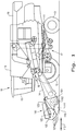
- FIG. 1 there is shown an exemplary embodiment of an agricultural vehicle in the form of a combine 10, which generally includes a chassis 11, ground engaging wheels 12 and 13, a header 100, a feeder housing 14, an operator cab 15, a threshing and separating system 16, a cleaning system 17, a grain tank 18, and an unloading auger 19.
- the agricultural vehicle is shown in the form of a combine harvester, it is also to be understood that the vehicle can take other forms.
- the vehicle can also be in the form of other types of self-propelled harvesters with headers, such as self-propelled windrowers, forage harvesters, sugarcane harvesters, cotton pickers, etc.
- Header 100 is mounted to the front of the combine 10 and includes a cutter 110, shown in Fig. 1 as a flexible cutter bar, for severing crops from a field during forward motion of combine 10.
- a rotatable reel 120 feeds the crop toward the cutter bar 110, and a double auger 102 feeds the severed crop laterally inwardly from each side toward feeder housing 14.
- Feeder housing 14 conveys the cut crop to threshing and separating system 16, and is selectively vertically movable using appropriate actuators, such as hydraulic cylinders (not shown).
- the header 100 includes a header frame 101 which is carried by the chassis 11 and is coupled to both the cutter bar 110 and the reel 120.
- the cutter bar 110 is movably coupled to the header frame 101 by, for example, an extendable cutter bar table 111 which is linked to an actuator and allows the cutter bar 110 to move in a fore-to-aft direction, signified by arrow 112.
- An example of a construction that can be used to movably couple the cutter bar 110 to the header frame 101 using an extendable cutter bar table 111 is described by U.S. Patent No. 7,730,707 , which is incorporated herein by reference, but it should be appreciated that any suitable way of movably coupling the cutter bar 110 to the header frame 101 can be used in accordance with embodiments of the present invention.
- a user can adjust the fore-to-aft position of the cutter bar 110 which will cut crops as the combine 10 traverses a field.
- the reel 120 includes a plurality of tines 121 that will grab crop material and direct it toward the cutter bar 110 as the reel 120 rotates about a reel axis of rotation 122.
- the reel 120 is pivotably coupled to the header frame 101 by a reel arm 123 which carries the reel 120.
- the reel arm 123 is pivotably coupled to the header frame 101 so forces acting on the reel arm 123 can cause the reel arm 123, and carried reel 120, to pivot about an arm pivot axis, which is omitted from view, as is known in the art.
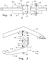
- a variable displacement fluid cylinder 200 formed according to the present invention which includes a cylinder housing 201 having an interior chamber 210 bounded by interior walls of the cylinder housing 201, a first piston 220 placed within the interior chamber 210, and a second piston 230 placed within the interior chamber 210.
- the cylinder 200 can be formed as a hydraulic cylinder having a cylindrical interior chamber 210 with a chamber diameter D1, with the first piston 220 and second piston 230 both having circular cross-sections of equal piston diameters D2 and D3 which are substantially equal to the chamber diameter D1.
- the interior chamber 210 defines a shared volume 211 between the first piston 220 and second piston 230, which can be filled with a force-transmitting fluid acting on both a first side 221 of the first piston 220 and a first side 231 of the second piston 230.
- the volume 211 between the first piston 220 and second piston 230 is "shared" in the sense that when a sufficient amount of fluid (liquid and/or gas) occupies the volume 211, the occupying fluid can act on both the first piston 220 and second piston 230, which will be described further herein.
- the occupying fluid can be, for example, a common hydraulic fluid such as oil which is non-compressible.
- the shared volume 211 can be filled with occupying fluid through a port 202 formed in the cylinder housing 201 which connects to a fluid supply 510 (shown in Fig. 5 ) carried by the vehicle 10, with the fluid supply 510 being able to provide fluid to or drain fluid from the interior chamber 210 to increase or decrease, respectively, the shared volume 211.
- the relative displacement L1 between the first piston 220 and second piston 230 can also be changed by a user to adjust the relative positioning between the cutter bar 110 and the reel 120 by adjusting the shared volume 211 as previously described. This allows the user to adjust the relative height of the reel 120 relative to the ground by adjusting the shared volume 211.
- the amount of fluid in the shared volume 211 can be held constant during operation of the header 100 so a relative displacement L1 between the first piston 220 and second piston 230 remains constant, the significance of which will be described further herein.
- the first piston 220 can be connected to a first piston rod 222 which extends out of the cylinder housing 201 and moves as the first piston 220 is displaced within the interior chamber 210.
- the first piston rod 222 can connect to the reel arm 123 so the first piston 220 is linked to the reel arm 123 such that displacement of the first piston 220 acts on the reel arm 123 to cause pivoting of the reel arm 123 relative to the header frame 101.
- the pivoting position of the reel arm 123 can be controlled by controlling the position of the first piston 220 within the interior chamber 210, and the position of the reel arm 123 and carried reel 120 can be adjusted by displacing the first piston 220 within the interior chamber 210.
- the interior chamber 210 can also include a first piston volume 213 on a second side 223 of the piston 220 which is opposite the shared volume 211.
- the first piston volume 213 can be filled with force-transmitting fluid, with the cylinder housing 201 also having a slave port 203 fluidly coupled to the first piston volume 213 of the interior chamber 210, the significance of which will be described further herein.
- the first piston volume 213 can vary based on the position of the first piston 220 within the interior chamber 210, the significance of which is also described further herein.
- the second piston 230 can be connected to a second piston rod 232 linking the second piston 230 to the cutter bar 110, which is further described herein.
- the cylinder 200 is shown with the first piston 220 linked to the reel arm 123 by the first piston rod 222 and the second piston 230 linked to the cutter bar 110 by the second piston rod 232 and a piston driver 300 shown as a cam system.
- the cam system 300 can include a cam 310 which is connected to the cutter bar table 111 so the cam 310 moves in the fore-to-aft direction 112 with the cutter bar table 111 and cutter bar 110.
- the cam 310 can have a pair of cam surfaces 311A, 311B which are angled with respect to the fore-to-aft direction 112, i.e., non-parallel to the fore-to-aft direction 112, such that the cam surfaces 311A, 311 B have varying vertical positions in the fore-to-aft direction 112.
- the cam system 300 can also include one or more cam followers 320 which are connected to the second piston rod 232 and in contact with the cam surfaces 311A, 311 B so that as the cam 310 moves in the fore-to-aft direction 112 with the cutter bar 110, the cam followers 320 move along the cam surfaces 311A, 311B and translate this movement into displacement of the second piston 230 within the interior chamber 210.
- the cam followers 320 are adjacent to a proximal end 312 of the cam 310, corresponding to the cutter bar 110 being extended outwardly from the header frame 101, with a corresponding position of the second piston 230 and first piston 220 within the interior chamber 210 of the cylinder 200.
- Fig. 3 the cam followers 320 are adjacent to a proximal end 312 of the cam 310, corresponding to the cutter bar 110 being extended outwardly from the header frame 101, with a corresponding position of the second piston 230 and first piston 220 within the interior chamber 210 of the cylinder 200.
- the first piston rod 222 connected to the first piston 220 has a first exposed rod length RL1 when the first piston 220 is in the position shown and the second piston rod 232 connected to the cam followers 320 has a second exposed rod length RL2 when the second piston 230 is in the position shown.
- the relative values of the exposed rod lengths RL1 and RL2 correlate to a pivot angle ⁇ of the reel arm 123 relative to its mounting point to the header frame 101, with the pivot angle ⁇ of the reel arm 123 controlling the relative position of the reel 120 relative to the cutter bar 110.
- a change in the exposed rod lengths RL1 and RL2 of the first piston rod 222 and second piston rod 232 changes the relative position of the reel 120 relative to the cutter bar 110.
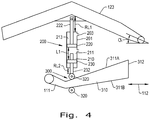
- FIG. 4 such a change in the exposed rod lengths RL1 and RL2 of the first piston rod 222 and second piston rod 232, respectively, is shown.
- the cam 310 has been moved in the fore-to-aft direction 112 with the cutter bar table 111 and cutter bar 110, corresponding to the cutter bar 110 being retracted, such that the cam followers 320 have moved along the cam surfaces 311 A, 311 B to a lower vertical position, pulling the second piston rod 232 (and the connected second piston 230) down and increasing the exposed second rod length RL2.
- the cylinder 200 is part of a closed fluid system 500 (shown in Fig.
- the exposed second rod length RL2 of the second piston rod 232 increases due to the cam followers 320 following the cam surfaces 311 A, 311 B as the cutter bar 110 is retracted, the exposed first rod length RL1 of the second piston rod 222 decreases and pulls the reel arm 123 down in the direction of the displacement of the second piston 230.
- the configuration of the cylinder 200 having the shared volume 211 between the first piston 220 and second piston 230 when occupied by force-transmitting fluid, allows movement of the cutter bar 110 in the fore-to-aft direction 112 to adjust the position of the reel 120 relative to the cutter bar 110.
- the reel 120 can be split into two reel sections 124A, 124B having reel ends 125A, 125B, 125C, and 125D with the cylinder 200 linked to reel end 125A by the reel arm 123.
- the vehicle 10 can include a closed fluid system 500 including one or more additional cylinders 520 and 530 which are driven by the cylinder 200 in a master-slave cylinder relationship.
- the additional cylinders 520 and 530 can be referred to as slave cylinders and the cylinder 200 can be referred to as a master cylinder.
- Each slave cylinder 520, 530 can include an interior fluid chamber 521, 531 with a piston 522, 532 placed within the interior fluid chamber 521, 531.
- the piston 522 is linked to both reel end 125B of reel section 124A and reel end 125C of reel section 120B by a piston rod 523 and reel arm 525 which supports both reel ends 125B and 125C while the piston 532 is linked to the reel end 125D by a piston rod 533 and reel arm 535 which supports reel end 125D.
- the slave cylinder 520 can have a first port 524A and a second port 524B fluidly coupled to the interior fluid chamber 521 while the slave cylinder 530 only has a single port 534A fluidly coupled to the interior fluid chamber 531.
- the slave port 203 of the cylinder 200 can be plumbed to the first port 524A of the slave cylinder 520 and the second port 524B of the slave cylinder 520 can be plumbed to the single port 534A of the slave cylinder 530 to form the closed fluid system 500, with the total volume of fluid in the closed fluid system 500 being held constant during operation. Since the total volume of fluid in the closed fluid system 500 is held constant, displacement of the first piston 220 within the interior chamber 210 displaces some or all of the fluid in the first piston volume 213, with the displaced fluid causing the pistons 522, 532 to similarly displace within their respective interior fluid chamber 521, 531.
- the displacement of the first piston 220 of the master cylinder 200 causes similar displacement of the pistons 522, 532 of the slave cylinders 520, 530, allowing the master cylinder 200 to simultaneously control the position of the two reel sections 120A and 120B relative to the cutter bar 110. Since the flow of fluid through the closed fluid system 500 responds near instantaneously to mechanical forces, there is virtually no lag in adjusting the positions of the reel sections 120A and 120B responsively to movement of the cutter bar 110 in the fore-to-aft direction 112, ensuring that the reel sections 120A and 120B properly move as the cutter bar 110 moves in the fore-to-aft direction 112.
- cylinders 200, 520, 530 together are collectively referred to as a closed fluid system herein due to the constant volume of fluid within the system 500
- one of the cylinders such as the master cylinder 200
- an alternative cylinder 600 can be used in place of the previously described cylinder 200.
- the cylinder 600 includes a cylinder housing 601 with an interior chamber 610 and a first piston 620 and a second piston 630 placed in the interior chamber 610 having a shared volume 611 between the first piston 620 and second piston 630.
- the first piston 620 can also have a piston rod 622 linking the first piston 620 to the reel arm 123, similarly to previously described first piston 220.
- the interior chamber 610 of the cylinder 600 has a second piston volume 614 on a second side 633 of the second piston 630 opposite the shared volume 611 which is fluidly coupled to an activating port 615 formed in the cylinder housing 601 so the second piston 630 is linked to the cutter bar 110 by a piston driver 640 shown as an activating cylinder.
- the activating cylinder 640 has an activating interior chamber 641 with an activating piston 642 which is placed in the activating interior chamber 641 and can be linked to the cutter bar 110 by an activating piston rod 643 connected to the cutter bar table 111.
- the activating interior chamber 641 can have an activating volume 644 which is fluidly coupled to a driving port 645 plumbed to the activating port 615 of the cylinder 600 so displacement of the activating piston 642 within the activating interior chamber 641 causes displacement of the second piston 630 within the interior chamber 610.
- the activating cylinder 640 can be the cylinder which is activated to move the cutter bar table 111 and connected cutter bar 110 in the fore-to-aft direction 112, or be a cylinder that is only utilized to displace the second piston 630 within the interior chamber 610.
- Figs. 7 and 8 it can be seen how displacement of the activating piston 642 causes displacement of the second piston 630, and thus displacement of the first piston 620 and adjustment of the position of the reel 120 relative to the cutter bar 110.
- the activating volume 644 of the activating interior chamber 641 decreases, displacing the fluid in the activating volume 644 into the second piston volume 614 of the cylinder 600 and causing a corresponding displacement of the second piston 630 and first piston 620 which raises the reel arm 123 and carried reel 120 relative to the cutter bar 110.
- the activating volume 644 of the activating interior chamber 641 increases, displacing the fluid in the second piston volume 614 into the activating volume 644 and causing a corresponding displacement of the second piston 630 and first piston 620 which lowers the reel arm 123 and carried reel 120 relative to the cutter bar 110.
- the second piston 630 is still linked to the cutter bar 110, but the link is caused by the shared volume of fluid acting on the second piston 630 and activating piston 642 rather than the mechanical piston driver 300 shown in Figs.
- the piston driver described herein can be a mechanical linkage, a fluid circuit, or a combination of a mechanical linkage and a fluid circuit.
- the second piston can be linked to the cutter bar 110 in a variety of different ways such that movement of the cutter bar 110 in the fore-to-aft direction 112 causes displacement of the second piston within the interior chamber, and that the exemplary embodiments shown and described herein are only some of the possible ways this link can be formed.
- the previously described exemplary embodiments of the present invention allow a user to control the position of the reel 120 relative to the cutter bar 110 both independently of and dependently on movement of the cutter bar 110, i.e., the user can adjust the position of the reel 120 relative to the ground by adjusting the shared volume without affecting the ability to maintain the relative position between the reel 120 and the cutter bar 110.
- a cutter bar 110 which is movably coupled to the header frame 101 by an extendable cutter bar table 111 to controllably move the cutter bar 110 in the fore-to-aft direction 112
- other types of movements of the cutter bar 110 can cause adjustment of the position of the reel 120 relative to the cutter bar 110 according to the present invention.
- a cutter bar 910 that is movably coupled to the header frame 101 by a flex arm 911, rather than an extendable cutter bar table, is shown.
- the flex arm 911 is pivotably coupled to the header frame 101 at a pivot 912 which defines an axis of rotation of the flex arm 911.
- the second piston 630 of the cylinder 600 can be linked to the activating cylinder 640 previously described, with the activating piston rod 643 linked to the flex arm 911 such that pivoting movement of the flex arm 911 and connected cutter bar 910 about the pivot axis 912 causes displacement of fluid in the activating volume 644 and a corresponding displacement of the second piston 630 and first piston 620 within the interior chamber 610 of the cylinder 600.
- the activating piston rod 643 can be linked to the flex arm 911 in a manner that displaces fluid from the activating volume 644 into the second piston volume 614 when the flex arm 911 and cutter bar 910 flex vertically upward about the pivot axis 912 so the second piston 630 and first piston 620 displace within the interior chamber 610 and raise the reel arm 123 and carried reel 120.
- the activating cylinder 640 is a float-type cylinder with fluid which displaces responsively to movement of the flex arm 911 and cutter bar 910, but may not be controlled to control relative movement between the cutter bar 910 and the header frame 101.
- the exemplary embodiments of the present invention can be readily adapted to allow varying types of movements of the cutter bar, other than fore-to-aft movement, to control the position of the reel arm 123 and carried reel 120 to avoid the tines 121 of the reel 120 contacting the cutter bar.
Landscapes
- Life Sciences & Earth Sciences (AREA)
- Environmental Sciences (AREA)
- Details Of Cutting Devices (AREA)
- Nonmetal Cutting Devices (AREA)
- Harvester Elements (AREA)
Abstract
Description
- The present invention relates to agricultural headers, and, more particularly, to agricultural headers with adjustable position cutters.
- Typically, a header for a harvesting machine includes a cutterbar which is operable to cut standing crop as the machine moves forward and a rotatable reel which carries tines to engage the standing crop and sweep it towards the cutterbar for cutting and then carry the cut material towards an auger before releasing it. The auger usually consolidates the cut crop material centrally of the header before it is passed to the body of the machine for processing. The distance between the cutterbar and the auger can depend on the type and condition of the crop to be harvested. Therefore, some header types have been provided with a cutterbar mounted to a forwardly extendable cutting table, enabling the operator of the harvesting machine to adapt its configuration when the crop condition or type changes.
- When harvesting down crops, i.e., crops that are not standing in a normal upright position, the relationships between the reel, the cutterbar and the auger can be important and, in general, the reel should be disposed so that the path described by the outer ends of the tines first enters the down crop forwardly of the cutterbar and below the level thereof for lifting the crop, then sweep closely over the cutterbar and finally pass in close proximity along the auger.
- Headers are known in which the cutterbar is vertically flexible along its length so that it can follow local irregularities in the ground. With such headers, it is necessary to be able to adjust the height of the reel relative to the highest point of the cutterbar at any given instant, otherwise the cutterbar is likely to foul the reel on flexing with consequential damage to one or both components. To this end, headers having flexible cutterbars have been fitted with means for automatically adjusting the position of the reel on vertical flexure of the cutterbar.
- Similar problems may occur when the cutterbar of an extendable header is set to a forwardmost position. Then the cutterbar will enter into the reel path that is required otherwise for harvesting down crops with a retracted cutting table. The tines or the bars of the reel may then damage the cutterbar or vice versa. Measures must be taken to prevent such interference and limit the path of the reel tines when the header is extended.
- One solution to these problems that has been incorporated in Varifeed™ headers sold by New Holland is to incorporate a cam system which adjusts the vertical position of the reel arm. The system includes a cylinder which is linked to the reel arm and has a cam follower in contact with a cam that moves with the cutterbar. As the cutterbar moves in the fore-to-aft direction, the cam moves and contact with the cam follower causes the cam follower to adjust the position of the cylinder, and thus the position of the reel arm. Such a system is effective in single span reels, but has not been found particularly effective in larger headers incorporating split reels which have multiple reel sections connected to multiple cylinders by multiple reel arms.
- One particular problem of known systems in split reel headers is coordinating movement of the reel arms together in response to fore-to-aft movement of the cutterbar. Typically, a split reel will be supported at both lateral ends and at the center of the reel by reel arms. The cylinder linked to the center of the reel is not able to be controlled by the cam system described above, while the lateral end cylinders are. Further, while electronically controlling the cylinders has shown promise in coordinating movement of the reel arms, such a system is prone to system lag or malfunction if a fault develops in the wiring.
- What is needed in the art is a reliable way to adjust the position of a single span or split reel responsively to fore-to-aft movement of the cutterbar.
- In accordance with an aspect of the present invention, there is provided a header with a reel carried by a reel arm which is adjusted by fluid movement in a closed fluid system caused by movement of a cutter.
- In accordance with another aspect of the present invention, there is provided an agricultural vehicle including a chassis and a header carried by the chassis. The header includes: a header frame; a cutter movably coupled to the header frame; a reel arm pivotably coupled to the header frame; a reel carried by the reel arm and including a plurality of tines; a variable displacement fluid cylinder including an interior chamber, a first piston linked to the reel arm placed within the interior chamber and a second piston placed within the interior chamber, the interior chamber defining a shared volume between the first piston and the second piston; and a piston driver linked to the cutter and configured to translate movement of the cutter relative to the header frame into displacement of the second piston within the interior chamber.
- In accordance with yet another aspect of the present invention, there is provided an agricultural vehicle including a chassis and a header carried by the chassis. The header includes: a header frame; a cutter movably coupled to the header frame and configured to move in a fore-to-aft direction; a reel arm pivotably coupled to the header frame; a reel carried by the reel arm and including a plurality of tines; and a variable displacement fluid cylinder including a first piston linked to the reel arm; a second piston linked to the cutter; and a shared volume of fluid between the first piston and the second piston, the second piston being linked to the cutter such that movement of the cutter relative to the header frame displaces the second piston and the first piston and causes pivoting of the reel arm.
- In accordance with yet another aspect of the present invention, there is provided a method of controlling a reel carried by a reel arm of an agricultural vehicle with respect to a position of a cutter, including: controllably moving the cutter, the cutter moving causing a displacement of a second piston within a variable displacement fluid cylinder; and displacing a first piston which is within the variable displacement fluid cylinder and is linked to the reel arm, the displacing being caused by a shared volume of fluid between the first piston and the second piston acting on the first piston responsively to the displacement of the second piston.
- An advantage of the agricultural vehicle described herein is that controlling the position of the reel relative to the cutter by displacement of the second piston linked to movement of the cutter provides a solution which can be easily scaled to simultaneously control the position of one or more reel sections of the reel.
- Another advantage of the agricultural vehicle described herein is that movement of fluid in the cylinder to adjust positioning of the reel displays virtually no lag and is not prone to malfunction caused by faulty electrical wiring.
- Still another advantage of the agricultural vehicle described herein is that the second piston can be linked to the cutter using either a mechanical or a fluid connection to control displacement of the second piston, providing a variety of options to control the reel relative to the cutter.
- Still another advantage of the agricultural vehicle described herein is the position of the reel relative to the ground can be adjusted for crop condition changes by adjusting the shared volume while still allowing the system to maintain the same relative positioning between the cutter and the reel when the cutter moves.
- The above-mentioned and other features and advantages of this invention, and the manner of attaining them, will become more apparent and the invention will be better understood by reference to the following description of exemplary embodiments of the invention taken in conjunction with the accompanying drawings, wherein:
-
Fig. 1 is a side view of an agricultural vehicle formed in accordance with an exemplary embodiment of the present invention; -
Fig. 2 is a cross-sectional view of a cylinder formed in accordance with an exemplary embodiment of the present invention; -
Fig. 3 is a cross-sectional view of the cylinder shown inFig. 2 when a cutter of the vehicle shown inFig. 1 is extended; -
Fig. 4 is a cross-sectional view of the cylinder system shown inFig. 3 when the cutter is retracted; -
Fig. 5 is a schematic diagram of a closed fluid system including the cylinder shown inFig. 2 linked to additional cylinders in accordance with an exemplary embodiment of the present invention -
Fig. 6 is a cross-sectional view of another closed fluid system formed in accordance with an exemplary embodiment of the present invention; -
Fig. 7 is a cross-sectional view of the closed fluid system shown inFig. 6 when a cutter of the vehicle shown inFig. 1 is extended; -
Fig. 8 is a cross-sectional view of the closed fluid system shown inFig. 6 when the cutter is retracted; and -
Fig. 9 is a side view of yet another exemplary embodiment of the present invention incorporating a cutter carried by a flex arm. - Corresponding reference characters indicate corresponding parts throughout the several views. The exemplifications set out herein illustrate embodiments of the invention and such exemplifications are not to be construed as limiting the scope of the invention in any manner.
- The terms "grain", "straw" and "tailings" are used principally throughout this specification for convenience but it is to be understood that these terms are not intended to be limiting. Thus "grain" refers to that part of the crop material which is threshed and separated from the discardable part of the crop material, which is referred to as non-grain crop material, MOG or straw. Incompletely threshed crop material is referred to as "tailings". Also the terms "forward", "rearward", "left" and "right", when used in connection with the agricultural harvester and/or components thereof are usually determined with reference to the direction of forward operative travel of the harvester, but again, they should not be construed as limiting. The terms "longitudinal" and "transverse" are determined with reference to the fore-and-aft direction of the agricultural harvester and are equally not to be construed as limiting.
- Referring now to the drawings, and more particularly to
Fig. 1 , there is shown an exemplary embodiment of an agricultural vehicle in the form of acombine 10, which generally includes achassis 11, groundengaging wheels header 100, afeeder housing 14, anoperator cab 15, a threshing and separatingsystem 16, acleaning system 17, agrain tank 18, and anunloading auger 19. - Although the agricultural vehicle is shown in the form of a combine harvester, it is also to be understood that the vehicle can take other forms. For example, the vehicle can also be in the form of other types of self-propelled harvesters with headers, such as self-propelled windrowers, forage harvesters, sugarcane harvesters, cotton pickers, etc.
-
Header 100 is mounted to the front of thecombine 10 and includes acutter 110, shown inFig. 1 as a flexible cutter bar, for severing crops from a field during forward motion ofcombine 10. Arotatable reel 120 feeds the crop toward thecutter bar 110, and adouble auger 102 feeds the severed crop laterally inwardly from each side towardfeeder housing 14.Feeder housing 14 conveys the cut crop to threshing and separatingsystem 16, and is selectively vertically movable using appropriate actuators, such as hydraulic cylinders (not shown). - The
header 100 includes aheader frame 101 which is carried by thechassis 11 and is coupled to both thecutter bar 110 and thereel 120. Thecutter bar 110 is movably coupled to theheader frame 101 by, for example, an extendable cutter bar table 111 which is linked to an actuator and allows thecutter bar 110 to move in a fore-to-aft direction, signified byarrow 112. An example of a construction that can be used to movably couple thecutter bar 110 to theheader frame 101 using an extendable cutter bar table 111 is described byU.S. Patent No. 7,730,707 , which is incorporated herein by reference, but it should be appreciated that any suitable way of movably coupling thecutter bar 110 to theheader frame 101 can be used in accordance with embodiments of the present invention. By movably coupling thecutter bar 110 to theheader frame 101, a user can adjust the fore-to-aft position of thecutter bar 110 which will cut crops as the combine 10 traverses a field. - The
reel 120, as shown, includes a plurality oftines 121 that will grab crop material and direct it toward thecutter bar 110 as thereel 120 rotates about a reel axis ofrotation 122. To adjust the relative positioning of thereel 120 relative to theheader frame 101, thereel 120 is pivotably coupled to theheader frame 101 by areel arm 123 which carries thereel 120. In this sense, thereel arm 123 is pivotably coupled to theheader frame 101 so forces acting on thereel arm 123 can cause thereel arm 123, and carriedreel 120, to pivot about an arm pivot axis, which is omitted from view, as is known in the art. - Referring now to
Fig. 2 , an exemplary embodiment of a variabledisplacement fluid cylinder 200 formed according to the present invention is shown which includes acylinder housing 201 having aninterior chamber 210 bounded by interior walls of thecylinder housing 201, afirst piston 220 placed within theinterior chamber 210, and asecond piston 230 placed within theinterior chamber 210. As can be seen, thecylinder 200 can be formed as a hydraulic cylinder having a cylindricalinterior chamber 210 with a chamber diameter D1, with thefirst piston 220 andsecond piston 230 both having circular cross-sections of equal piston diameters D2 and D3 which are substantially equal to the chamber diameter D1. In such a configuration, theinterior chamber 210 defines a sharedvolume 211 between thefirst piston 220 andsecond piston 230, which can be filled with a force-transmitting fluid acting on both afirst side 221 of thefirst piston 220 and afirst side 231 of thesecond piston 230. As used herein, thevolume 211 between thefirst piston 220 andsecond piston 230 is "shared" in the sense that when a sufficient amount of fluid (liquid and/or gas) occupies thevolume 211, the occupying fluid can act on both thefirst piston 220 andsecond piston 230, which will be described further herein. The occupying fluid can be, for example, a common hydraulic fluid such as oil which is non-compressible. The sharedvolume 211 can be filled with occupying fluid through aport 202 formed in thecylinder housing 201 which connects to a fluid supply 510 (shown inFig. 5 ) carried by thevehicle 10, with thefluid supply 510 being able to provide fluid to or drain fluid from theinterior chamber 210 to increase or decrease, respectively, the sharedvolume 211. The relative displacement L1 between thefirst piston 220 andsecond piston 230 can also be changed by a user to adjust the relative positioning between thecutter bar 110 and thereel 120 by adjusting the sharedvolume 211 as previously described. This allows the user to adjust the relative height of thereel 120 relative to the ground by adjusting the sharedvolume 211. To maintain consistent force-transmitting properties of the fluid occupying the sharedvolume 211, the amount of fluid in the sharedvolume 211 can be held constant during operation of theheader 100 so a relative displacement L1 between thefirst piston 220 andsecond piston 230 remains constant, the significance of which will be described further herein. - The
first piston 220 can be connected to afirst piston rod 222 which extends out of thecylinder housing 201 and moves as thefirst piston 220 is displaced within theinterior chamber 210. Thefirst piston rod 222 can connect to thereel arm 123 so thefirst piston 220 is linked to thereel arm 123 such that displacement of thefirst piston 220 acts on thereel arm 123 to cause pivoting of thereel arm 123 relative to theheader frame 101. In this sense, the pivoting position of thereel arm 123 can be controlled by controlling the position of thefirst piston 220 within theinterior chamber 210, and the position of thereel arm 123 and carriedreel 120 can be adjusted by displacing thefirst piston 220 within theinterior chamber 210. Theinterior chamber 210 can also include afirst piston volume 213 on asecond side 223 of thepiston 220 which is opposite the sharedvolume 211. Thefirst piston volume 213 can be filled with force-transmitting fluid, with thecylinder housing 201 also having aslave port 203 fluidly coupled to thefirst piston volume 213 of theinterior chamber 210, the significance of which will be described further herein. As thefirst piston volume 213 is bounded by interior walls of theinterior chamber 210 on thesecond side 223 of thefirst piston 220, thefirst piston volume 213 can vary based on the position of thefirst piston 220 within theinterior chamber 210, the significance of which is also described further herein. Similarly, thesecond piston 230 can be connected to asecond piston rod 232 linking thesecond piston 230 to thecutter bar 110, which is further described herein. - Referring now to
Fig. 3 , thecylinder 200 is shown with thefirst piston 220 linked to thereel arm 123 by thefirst piston rod 222 and thesecond piston 230 linked to thecutter bar 110 by thesecond piston rod 232 and apiston driver 300 shown as a cam system. Thecam system 300 can include acam 310 which is connected to the cutter bar table 111 so thecam 310 moves in the fore-to-aft direction 112 with the cutter bar table 111 andcutter bar 110. As can be seen, thecam 310 can have a pair of cam surfaces 311A, 311B which are angled with respect to the fore-to-aft direction 112, i.e., non-parallel to the fore-to-aft direction 112, such that the cam surfaces 311A, 311 B have varying vertical positions in the fore-to-aft direction 112. Thecam system 300 can also include one ormore cam followers 320 which are connected to thesecond piston rod 232 and in contact with the cam surfaces 311A, 311 B so that as thecam 310 moves in the fore-to-aft direction 112 with thecutter bar 110, thecam followers 320 move along the cam surfaces 311A, 311B and translate this movement into displacement of thesecond piston 230 within theinterior chamber 210. As shown inFig. 3 , thecam followers 320 are adjacent to aproximal end 312 of thecam 310, corresponding to thecutter bar 110 being extended outwardly from theheader frame 101, with a corresponding position of thesecond piston 230 andfirst piston 220 within theinterior chamber 210 of thecylinder 200. As further shown inFig. 3 , thefirst piston rod 222 connected to thefirst piston 220 has a first exposed rod length RL1 when thefirst piston 220 is in the position shown and thesecond piston rod 232 connected to thecam followers 320 has a second exposed rod length RL2 when thesecond piston 230 is in the position shown. When thecylinder 200 is statically mounted relative to theheader frame 101, the relative values of the exposed rod lengths RL1 and RL2 correlate to a pivot angle α of thereel arm 123 relative to its mounting point to theheader frame 101, with the pivot angle α of thereel arm 123 controlling the relative position of thereel 120 relative to thecutter bar 110. Thus, a change in the exposed rod lengths RL1 and RL2 of thefirst piston rod 222 andsecond piston rod 232, respectively, changes the relative position of thereel 120 relative to thecutter bar 110. - Referring now to
Fig. 4 , such a change in the exposed rod lengths RL1 and RL2 of thefirst piston rod 222 andsecond piston rod 232, respectively, is shown. As can be seen, thecam 310 has been moved in the fore-to-aft direction 112 with the cutter bar table 111 andcutter bar 110, corresponding to thecutter bar 110 being retracted, such that thecam followers 320 have moved along the cam surfaces 311 A, 311 B to a lower vertical position, pulling the second piston rod 232 (and the connected second piston 230) down and increasing the exposed second rod length RL2. Since thecylinder 200 is part of a closed fluid system 500 (shown inFig. 5 ) and the sharedvolume 211 is held constant so the relative displacement L1 between thefirst piston 220 andsecond piston 230 is constant, displacement of thesecond piston 230 from the position shown inFig. 3 to the position shown inFig. 4 also displaces thefirst piston 220 in the same direction that thesecond piston 230 is displaced to maintain the constant relative displacement L1, which can be seen by comparing the positions of thefirst piston 220 within theinterior chamber 210 inFigs. 3 and4 . Thus, when the exposed second rod length RL2 of thesecond piston rod 232 increases due to thecam followers 320 following the cam surfaces 311 A, 311 B as thecutter bar 110 is retracted, the exposed first rod length RL1 of thesecond piston rod 222 decreases and pulls thereel arm 123 down in the direction of the displacement of thesecond piston 230. It should thus be appreciated that the configuration of thecylinder 200 having the sharedvolume 211 between thefirst piston 220 andsecond piston 230, when occupied by force-transmitting fluid, allows movement of thecutter bar 110 in the fore-to-aft direction 112 to adjust the position of thereel 120 relative to thecutter bar 110. - To illustrate the significance of the above-described configuration in the context of a split reel system, reference is now made to
Fig. 5 . As can be seen, thereel 120 can be split into tworeel sections cylinder 200 linked to reelend 125A by thereel arm 123. To coordinate the positioning of thereel sections vehicle 10 can include aclosed fluid system 500 including one or moreadditional cylinders cylinder 200 in a master-slave cylinder relationship. In this sense, theadditional cylinders cylinder 200 can be referred to as a master cylinder. Eachslave cylinder interior fluid chamber piston interior fluid chamber piston 522 is linked to bothreel end 125B ofreel section 124A and reelend 125C of reel section 120B by apiston rod 523 andreel arm 525 which supports both reel ends 125B and 125C while thepiston 532 is linked to thereel end 125D by apiston rod 533 andreel arm 535 which supportsreel end 125D. Theslave cylinder 520 can have afirst port 524A and asecond port 524B fluidly coupled to theinterior fluid chamber 521 while theslave cylinder 530 only has asingle port 534A fluidly coupled to theinterior fluid chamber 531. - The
slave port 203 of thecylinder 200 can be plumbed to thefirst port 524A of theslave cylinder 520 and thesecond port 524B of theslave cylinder 520 can be plumbed to thesingle port 534A of theslave cylinder 530 to form theclosed fluid system 500, with the total volume of fluid in theclosed fluid system 500 being held constant during operation. Since the total volume of fluid in theclosed fluid system 500 is held constant, displacement of thefirst piston 220 within theinterior chamber 210 displaces some or all of the fluid in thefirst piston volume 213, with the displaced fluid causing thepistons fluid chamber first piston 220 of themaster cylinder 200 causes similar displacement of thepistons slave cylinders master cylinder 200 to simultaneously control the position of the two reel sections 120A and 120B relative to thecutter bar 110. Since the flow of fluid through theclosed fluid system 500 responds near instantaneously to mechanical forces, there is virtually no lag in adjusting the positions of the reel sections 120A and 120B responsively to movement of thecutter bar 110 in the fore-to-aft direction 112, ensuring that the reel sections 120A and 120B properly move as thecutter bar 110 moves in the fore-to-aft direction 112. It should be appreciated that while all of thecylinders system 500, one of the cylinders, such as themaster cylinder 200, can also be configured as a closed fluid system in an exemplary embodiment of the present invention; in the case of themaster cylinder 200, plugging, sealing, or otherwise obstructing theslave port 203 could allow themaster cylinder 200 to function as a closed fluid system. - In another exemplary embodiment of the present invention, and referring now to
Figs. 6-8 , analternative cylinder 600 can be used in place of the previously describedcylinder 200. For convenience of description, all of the elements of thecylinder 600 which are similar to an element of thecylinder 200 are assigned the same reference numeral raised by 400. As can be seen, thecylinder 600 includes acylinder housing 601 with aninterior chamber 610 and afirst piston 620 and asecond piston 630 placed in theinterior chamber 610 having a sharedvolume 611 between thefirst piston 620 andsecond piston 630. Thefirst piston 620 can also have apiston rod 622 linking thefirst piston 620 to thereel arm 123, similarly to previously describedfirst piston 220. Unlike thecylinder 200, however, theinterior chamber 610 of thecylinder 600 has asecond piston volume 614 on asecond side 633 of thesecond piston 630 opposite the sharedvolume 611 which is fluidly coupled to an activatingport 615 formed in thecylinder housing 601 so thesecond piston 630 is linked to thecutter bar 110 by apiston driver 640 shown as an activating cylinder. The activatingcylinder 640 has an activatinginterior chamber 641 with an activatingpiston 642 which is placed in the activatinginterior chamber 641 and can be linked to thecutter bar 110 by an activatingpiston rod 643 connected to the cutter bar table 111. The activatinginterior chamber 641 can have an activatingvolume 644 which is fluidly coupled to a drivingport 645 plumbed to the activatingport 615 of thecylinder 600 so displacement of the activatingpiston 642 within the activatinginterior chamber 641 causes displacement of thesecond piston 630 within theinterior chamber 610. The activatingcylinder 640 can be the cylinder which is activated to move the cutter bar table 111 and connectedcutter bar 110 in the fore-to-aft direction 112, or be a cylinder that is only utilized to displace thesecond piston 630 within theinterior chamber 610. - Referring specifically now to
Figs. 7 and 8 , it can be seen how displacement of the activatingpiston 642 causes displacement of thesecond piston 630, and thus displacement of thefirst piston 620 and adjustment of the position of thereel 120 relative to thecutter bar 110. As shown inFig. 7 , when thecutter bar 110 is extended outwardly, the activatingvolume 644 of the activatinginterior chamber 641 decreases, displacing the fluid in the activatingvolume 644 into thesecond piston volume 614 of thecylinder 600 and causing a corresponding displacement of thesecond piston 630 andfirst piston 620 which raises thereel arm 123 and carriedreel 120 relative to thecutter bar 110. When the cutter bar table 111 andcutter bar 110 are moved in the fore-to-aft direction 112 so thecutter bar 110 is retracted, the activatingvolume 644 of the activatinginterior chamber 641 increases, displacing the fluid in thesecond piston volume 614 into the activatingvolume 644 and causing a corresponding displacement of thesecond piston 630 andfirst piston 620 which lowers thereel arm 123 and carriedreel 120 relative to thecutter bar 110. It should thus be appreciated that thesecond piston 630 is still linked to thecutter bar 110, but the link is caused by the shared volume of fluid acting on thesecond piston 630 and activatingpiston 642 rather than themechanical piston driver 300 shown inFigs. 3-4 , i.e., the piston driver described herein can be a mechanical linkage, a fluid circuit, or a combination of a mechanical linkage and a fluid circuit. It should be further appreciated that the second piston can be linked to thecutter bar 110 in a variety of different ways such that movement of thecutter bar 110 in the fore-to-aft direction 112 causes displacement of the second piston within the interior chamber, and that the exemplary embodiments shown and described herein are only some of the possible ways this link can be formed. It should be further appreciated that the previously described exemplary embodiments of the present invention allow a user to control the position of thereel 120 relative to thecutter bar 110 both independently of and dependently on movement of thecutter bar 110, i.e., the user can adjust the position of thereel 120 relative to the ground by adjusting the shared volume without affecting the ability to maintain the relative position between thereel 120 and thecutter bar 110. - While the previously described exemplary embodiments of the present invention include a
cutter bar 110 which is movably coupled to theheader frame 101 by an extendable cutter bar table 111 to controllably move thecutter bar 110 in the fore-to-aft direction 112, other types of movements of thecutter bar 110 can cause adjustment of the position of thereel 120 relative to thecutter bar 110 according to the present invention. In one such exemplary embodiment, and referring now toFig. 9 , acutter bar 910 that is movably coupled to theheader frame 101 by aflex arm 911, rather than an extendable cutter bar table, is shown. As can be seen, theflex arm 911 is pivotably coupled to theheader frame 101 at apivot 912 which defines an axis of rotation of theflex arm 911. Thesecond piston 630 of thecylinder 600 can be linked to the activatingcylinder 640 previously described, with the activatingpiston rod 643 linked to theflex arm 911 such that pivoting movement of theflex arm 911 and connectedcutter bar 910 about thepivot axis 912 causes displacement of fluid in the activatingvolume 644 and a corresponding displacement of thesecond piston 630 andfirst piston 620 within theinterior chamber 610 of thecylinder 600. For example, the activatingpiston rod 643 can be linked to theflex arm 911 in a manner that displaces fluid from the activatingvolume 644 into thesecond piston volume 614 when theflex arm 911 andcutter bar 910 flex vertically upward about thepivot axis 912 so thesecond piston 630 andfirst piston 620 displace within theinterior chamber 610 and raise thereel arm 123 and carriedreel 120. In such a configuration, the activatingcylinder 640 is a float-type cylinder with fluid which displaces responsively to movement of theflex arm 911 andcutter bar 910, but may not be controlled to control relative movement between thecutter bar 910 and theheader frame 101. It should thus be appreciated that the exemplary embodiments of the present invention can be readily adapted to allow varying types of movements of the cutter bar, other than fore-to-aft movement, to control the position of thereel arm 123 and carriedreel 120 to avoid thetines 121 of thereel 120 contacting the cutter bar. - While this invention has been described with respect to at least one embodiment, the present invention can be further modified within the spirit and scope of this disclosure. This application is therefore intended to cover any variations, uses, or adaptations of the invention using its general principles. Further, this application is intended to cover such departures from the present disclosure as come within known or customary practice in the art to which this invention pertains and which fall within the limits of the appended claims.
Claims (13)
- An agricultural vehicle (10), comprising:- a chassis (11); and- a header (100) carried by said chassis (11), said header (100) including:- a header frame (101);- a cutter (110, 910) movably coupled to said header frame (101);- a reel arm (123, 525, 535) pivotably coupled to said header frame (101); and- a reel (120) carried by said reel arm (123, 525, 535) and including a plurality of tines (121);characterized by:- a variable displacement fluid cylinder (200, 600) including an interior chamber (210, 610), a first piston (220, 620) linked to said reel arm (123, 525, 535) placed within said interior chamber (210, 610) and a second piston (230, 630) placed within said interior chamber (210, 610), said interior chamber (210, 610) defining a shared volume (211, 611) between said first piston (220, 620) and said second piston (230, 630); and- a piston driver (300, 640) linked to said cutter (110, 910), said piston driver (300, 640) being configured to translate movement of said cutter (110, 910) relative to said header frame (101) into displacement of said second piston (230, 630) within said interior chamber (210, 610).
- The agricultural vehicle (10) of claim 1, wherein said variable displacement fluid cylinder (200, 600) includes a force-transmitting fluid at least partially filling said shared volume (211, 611) and displacement of said second piston (230, 630) within said interior chamber (210, 610) displaces said first piston (230, 630) within said interior chamber (210,610).
- The agricultural vehicle (10) of claim 1, further comprising an additional cylinder (520, 530) including a fluid chamber (521, 531) and a piston (522, 532) placed in said fluid chamber (521, 531) which is linked to said reel (120).
- The agricultural vehicle (10) of claim 3, wherein said interior chamber (210) of said cylinder (200) defines a first piston volume (213) on a side (223) of said first piston (220) opposite said shared volume (211), said additional cylinder (520) having a port (524A) fluidly coupling said fluid chamber (521) to said first piston volume (213) of said interior chamber (210).
- The agricultural vehicle (10) of claim 4, wherein said reel (120) includes a first reel section (124A) linked to said first piston (220) and a second reel section (124B) linked to said piston (522) of said additional cylinder (520).
- The agricultural vehicle (10) of claim 1, wherein said cutter (110) is configured to move in a fore-to-aft direction (112) relative to said header frame (101), said piston driver (300) comprising a cam (310) connected to said cutter (110) such that said cam (310) moves in the fore-to-aft direction (112) with said cutter (110) and a cam follower (320) linked to said second piston (230) and contacting said cam (310).
- The agricultural vehicle (10) of claim 6, wherein said cam (310) includes at least one surface (311A, 311 B) which is angled with respect to the fore-to-aft direction (112), said cam follower (320) contacting said at least one surface (311A, 311B) of said cam (310).
- The agricultural vehicle (10) of claim 1, wherein said piston driver (640) is an activating cylinder including an activating interior chamber (641) with an activating piston (642) linked to said cutter (110, 910) placed within said activating interior chamber (641).
- The agricultural vehicle (10) of claim 8, wherein said interior chamber (610) of said cylinder (600) defines a second piston volume (614) on a side (633) of said second piston (630) opposite said shared volume (611) which is fluidly coupled to said activating interior chamber (641).
- A method of controlling a reel (120) carried by a reel arm (123, 525, 535) of an agricultural vehicle (10) with respect to a position of a cutter (110, 910), comprising:- controllably moving said cutter (110, 910);characterized by:- said cutter (110, 910) moving causing a displacement of a second piston (230, 630) within a variable displacement fluid cylinder (200, 600); and- displacing a first piston (220, 620) which is within said variable displacement fluid cylinder (200, 600) and is linked to said reel arm (123, 525, 535), said displacing being caused by a shared volume of fluid (211, 611) between said first piston (220, 620) and said second piston (230, 630) acting on said first piston (220, 620) responsively to said displacement of said second piston (230, 630).
- The method of claim 10, wherein said second piston (230) is connected to a cam follower (320), said cam follower (320) being connected to a cam (310) carried by said cutter (110).
- The method of claim 10, wherein said agricultural vehicle (10) includes an activating cylinder (640) which includes an activating interior chamber (641) and an activating piston (642) linked to said cutter (110, 910) placed within said activating interior chamber (641), said variable displacement fluid cylinder (600) including a second piston volume of fluid (614) which is on a side (633) of said second piston (630) opposite said shared volume of fluid (611) and is fluidly coupled to said activating interior chamber (641).
- The method of claim 10, wherein said moving of said cutter (110) occurs in a fore-to-aft direction (112).
Applications Claiming Priority (1)
| Application Number | Priority Date | Filing Date | Title |
|---|---|---|---|
| US15/285,982 US10034428B2 (en) | 2016-10-05 | 2016-10-05 | Agricultural header with cutter tracking reel |
Publications (2)
| Publication Number | Publication Date |
|---|---|
| EP3305058A1 true EP3305058A1 (en) | 2018-04-11 |
| EP3305058B1 EP3305058B1 (en) | 2019-08-28 |
Family
ID=60019780
Family Applications (1)
| Application Number | Title | Priority Date | Filing Date |
|---|---|---|---|
| EP17194688.2A Active EP3305058B1 (en) | 2016-10-05 | 2017-10-04 | Agricultural header with cutter tracking reel |
Country Status (4)
| Country | Link |
|---|---|
| US (1) | US10034428B2 (en) |
| EP (1) | EP3305058B1 (en) |
| AU (1) | AU2017239527B2 (en) |
| CA (1) | CA2978984C (en) |
Cited By (3)
| Publication number | Priority date | Publication date | Assignee | Title |
|---|---|---|---|---|
| WO2019234539A1 (en) * | 2018-06-08 | 2019-12-12 | Agco Corporation | Auto reel height |
| WO2020176739A1 (en) * | 2019-02-27 | 2020-09-03 | Cnh Industrial America Llc | Reel assembly of an agricultural header |
| WO2021216791A1 (en) * | 2020-04-21 | 2021-10-28 | Cnh Industrial America Llc | Reel adjustment for an agricultural header |
Families Citing this family (5)
| Publication number | Priority date | Publication date | Assignee | Title |
|---|---|---|---|---|
| US12396399B2 (en) * | 2019-04-10 | 2025-08-26 | Gts Do Brasil Ltda. | Reel and cutter bar floating system for a combine harvester platform, combine harvester platform and agricultural machine |
| US11617304B2 (en) | 2019-10-25 | 2023-04-04 | Cnh Industrial America Llc | Staggered harvester head reel position adjustment |
| US11337371B2 (en) * | 2019-12-23 | 2022-05-24 | Cnh Industrial America Llc | Systems and methods for limiting reel adjustment in an agricultural header |
| WO2021258067A1 (en) | 2020-06-19 | 2021-12-23 | Cnh Industrial America Llc | Trunnion-mounted actuator assembly |
| US20230397537A1 (en) * | 2020-10-16 | 2023-12-14 | Macdon Industries Ltd. | Draper header with automatic reel to cutter bar clearance |
Citations (5)
| Publication number | Priority date | Publication date | Assignee | Title |
|---|---|---|---|---|
| US4124970A (en) * | 1977-06-03 | 1978-11-14 | Sperry Rand Corporation | Automatic reel height control for a harvester header having a flexible cutterbar |
| EP0250650A1 (en) * | 1986-06-24 | 1988-01-07 | FORD NEW HOLLAND, INC. (a Delaware corp.) | Header for harvesting machine |
| EP2055173A1 (en) * | 2007-10-29 | 2009-05-06 | CNH Belgium N.V. | Automatic control system for a header of an agricultural harvesting machine and method of operation of the same |
| US7730707B2 (en) | 2008-07-11 | 2010-06-08 | Cnh America Llc | Extendable header for harvesting machine |
| WO2014025346A1 (en) * | 2012-08-08 | 2014-02-13 | Cnh America Llc | Automatic control of relative positioning of cutter bar and reel |
Family Cites Families (19)
| Publication number | Priority date | Publication date | Assignee | Title |
|---|---|---|---|---|
| US2795920A (en) * | 1956-10-01 | 1957-06-18 | Deere & Co | Adjustable harvester reel mounting |
| US2873567A (en) * | 1957-03-04 | 1959-02-17 | Deere & Co | Adjustable reel mount for harvester |
| US3347029A (en) * | 1964-08-20 | 1967-10-17 | Kenneth E Grinwald | Aquatic harvester |
| US3623301A (en) * | 1969-07-23 | 1971-11-30 | Bosch Gmbh Robert | Control apparatus for the cutting platform of a harvesting machine |
| US4011709A (en) * | 1974-11-13 | 1977-03-15 | Deere & Company | Harvesting platform |
| US4204383A (en) | 1978-06-29 | 1980-05-27 | Allis-Chalmers Corporation | Automatic height control for gathering reel for agricultural combine |
| US4444000A (en) * | 1982-06-01 | 1984-04-24 | Allis-Chalmers Corporation | Harvester header construction |
| US4641490A (en) * | 1985-04-12 | 1987-02-10 | New Holland Inc. | Header height/lateral float control for combine header |
| US4655031A (en) * | 1985-07-24 | 1987-04-07 | J. I. Case Company | Phasing circuit for serially |
| DE3634577C2 (en) | 1986-10-10 | 1995-03-23 | Claas Saulgau Gmbh | Cradle for agricultural Machines such as forage harvesters |
| DE4021030C2 (en) * | 1990-07-03 | 1994-10-06 | Gustav Schumacher | Mowing table for harvesting machines |
| DE19504244C2 (en) * | 1995-02-09 | 1996-12-12 | Claas Ohg | Self-propelled combine harvester with a two-part cutting table |
| DE19508887C2 (en) | 1995-03-11 | 1999-01-07 | Claas Ohg | Self-propelled harvesting machine with two-part cutting trough |
| DE19639217C5 (en) * | 1995-09-29 | 2009-07-16 | Claas Kgaa Mbh | Agricultural machine |
| US20070193243A1 (en) * | 2006-02-10 | 2007-08-23 | Schmidt James R | Combine Harvester Draper Header Having Flexible Cutterbar |
| US7866132B2 (en) * | 2009-05-20 | 2011-01-11 | Deere & Company | Harvesting head reel support arrangement including hydraulic cylinders and control circuitry |
| US7971418B2 (en) * | 2009-07-09 | 2011-07-05 | Deere & Company | Header with extendible cutter bar |
| US7992374B1 (en) * | 2010-04-06 | 2011-08-09 | Cnh America Llc | Agricultural plant cutting header with fore and aft adjustable flexible cutterbar having automatic preload adjustment |
| DE102013101444A1 (en) * | 2013-02-14 | 2014-08-14 | Claas Selbstfahrende Erntemaschinen Gmbh | Method for operating a self-propelled harvester and self-propelled harvester |
-
2016
- 2016-10-05 US US15/285,982 patent/US10034428B2/en active Active
-
2017
- 2017-09-12 CA CA2978984A patent/CA2978984C/en active Active
- 2017-10-04 AU AU2017239527A patent/AU2017239527B2/en active Active
- 2017-10-04 EP EP17194688.2A patent/EP3305058B1/en active Active
Patent Citations (5)
| Publication number | Priority date | Publication date | Assignee | Title |
|---|---|---|---|---|
| US4124970A (en) * | 1977-06-03 | 1978-11-14 | Sperry Rand Corporation | Automatic reel height control for a harvester header having a flexible cutterbar |
| EP0250650A1 (en) * | 1986-06-24 | 1988-01-07 | FORD NEW HOLLAND, INC. (a Delaware corp.) | Header for harvesting machine |
| EP2055173A1 (en) * | 2007-10-29 | 2009-05-06 | CNH Belgium N.V. | Automatic control system for a header of an agricultural harvesting machine and method of operation of the same |
| US7730707B2 (en) | 2008-07-11 | 2010-06-08 | Cnh America Llc | Extendable header for harvesting machine |
| WO2014025346A1 (en) * | 2012-08-08 | 2014-02-13 | Cnh America Llc | Automatic control of relative positioning of cutter bar and reel |
Cited By (6)
| Publication number | Priority date | Publication date | Assignee | Title |
|---|---|---|---|---|
| WO2019234539A1 (en) * | 2018-06-08 | 2019-12-12 | Agco Corporation | Auto reel height |
| US11903342B2 (en) | 2018-06-08 | 2024-02-20 | Agco Corporation | Auto reel height |
| WO2020176739A1 (en) * | 2019-02-27 | 2020-09-03 | Cnh Industrial America Llc | Reel assembly of an agricultural header |
| US12329068B2 (en) | 2019-02-27 | 2025-06-17 | Cnh Industrial America Llc | Reel assembly of an agricultural header |
| WO2021216791A1 (en) * | 2020-04-21 | 2021-10-28 | Cnh Industrial America Llc | Reel adjustment for an agricultural header |
| US12507630B2 (en) | 2020-04-21 | 2025-12-30 | Cnh Industrial America Llc | Reel adjustment for an agricultural header |
Also Published As
| Publication number | Publication date |
|---|---|
| AU2017239527A1 (en) | 2018-04-19 |
| EP3305058B1 (en) | 2019-08-28 |
| CA2978984C (en) | 2023-04-18 |
| AU2017239527B2 (en) | 2021-09-30 |
| US10034428B2 (en) | 2018-07-31 |
| US20180092305A1 (en) | 2018-04-05 |
| CA2978984A1 (en) | 2018-04-05 |
Similar Documents
| Publication | Publication Date | Title |
|---|---|---|
| EP3305058B1 (en) | Agricultural header with cutter tracking reel | |
| EP3473076B1 (en) | Self-contained combine draper wing leveler | |
| US10257979B2 (en) | Harvester header pitch adjustment apparatus | |
| EP3469876B1 (en) | System for wing float on a combine draper header | |
| US9788486B2 (en) | Grain header with swathing and chopping capability | |
| US10182525B2 (en) | Feeder and header positioning method | |
| EP2764765B1 (en) | Combine harvester with feederhouse arrangement | |
| EP3363276A1 (en) | Combination flex and rigid header height control in a harvester | |
| EP3629698B1 (en) | Hydraulic system for a header of an agricultural harvester | |
| US20090107094A1 (en) | Automatic control system for a header of an agricultural harvesting machine and method of operation of the same | |
| US11553645B2 (en) | Flex arm air bag linkage | |
| US20140041352A1 (en) | Automatic Header Electronic Pitch Control | |
| US12245552B2 (en) | Adjustable reel arm | |
| EP3998845B1 (en) | Feederhouse assemblies, agricultural harvesters, and methods of connecting harvesting headers to agricultural harvesters | |
| US20240245001A1 (en) | Independent reel position control for an agricultural harvester header | |
| EP3791710B1 (en) | Feederhouse assembly having a rotational shaft with fluid passages | |
| BR112020004705B1 (en) | FLEXIBLE PLATFORM FOR AN AGRICULTURAL VEHICLE AND METHOD FOR ADJUSTING A FLEXIBLE CUTTING BAR OF A PLATFORM |
Legal Events
| Date | Code | Title | Description |
|---|---|---|---|
| PUAI | Public reference made under article 153(3) epc to a published international application that has entered the european phase |
Free format text: ORIGINAL CODE: 0009012 |
|
| STAA | Information on the status of an ep patent application or granted ep patent |
Free format text: STATUS: THE APPLICATION HAS BEEN PUBLISHED |
|
| AK | Designated contracting states |
Kind code of ref document: A1 Designated state(s): AL AT BE BG CH CY CZ DE DK EE ES FI FR GB GR HR HU IE IS IT LI LT LU LV MC MK MT NL NO PL PT RO RS SE SI SK SM TR |
|
| AX | Request for extension of the european patent |
Extension state: BA ME |
|
| STAA | Information on the status of an ep patent application or granted ep patent |
Free format text: STATUS: REQUEST FOR EXAMINATION WAS MADE |
|
| 17P | Request for examination filed |
Effective date: 20181011 |
|
| RBV | Designated contracting states (corrected) |
Designated state(s): AL AT BE BG CH CY CZ DE DK EE ES FI FR GB GR HR HU IE IS IT LI LT LU LV MC MK MT NL NO PL PT RO RS SE SI SK SM TR |
|
| GRAP | Despatch of communication of intention to grant a patent |
Free format text: ORIGINAL CODE: EPIDOSNIGR1 |
|
| STAA | Information on the status of an ep patent application or granted ep patent |
Free format text: STATUS: GRANT OF PATENT IS INTENDED |
|
| RIC1 | Information provided on ipc code assigned before grant |
Ipc: A01D 57/04 20060101AFI20190226BHEP |
|
| INTG | Intention to grant announced |
Effective date: 20190401 |
|
| GRAS | Grant fee paid |
Free format text: ORIGINAL CODE: EPIDOSNIGR3 |
|
| GRAA | (expected) grant |
Free format text: ORIGINAL CODE: 0009210 |
|
| STAA | Information on the status of an ep patent application or granted ep patent |
Free format text: STATUS: THE PATENT HAS BEEN GRANTED |
|
| AK | Designated contracting states |
Kind code of ref document: B1 Designated state(s): AL AT BE BG CH CY CZ DE DK EE ES FI FR GB GR HR HU IE IS IT LI LT LU LV MC MK MT NL NO PL PT RO RS SE SI SK SM TR |
|
| REG | Reference to a national code |
Ref country code: GB Ref legal event code: FG4D |
|
| REG | Reference to a national code |
Ref country code: CH Ref legal event code: EP |
|
| REG | Reference to a national code |
Ref country code: AT Ref legal event code: REF Ref document number: 1171252 Country of ref document: AT Kind code of ref document: T Effective date: 20190915 |
|
| REG | Reference to a national code |
Ref country code: IE Ref legal event code: FG4D |
|
| REG | Reference to a national code |
Ref country code: DE Ref legal event code: R096 Ref document number: 602017006509 Country of ref document: DE |
|
| REG | Reference to a national code |
Ref country code: NL Ref legal event code: MP Effective date: 20190828 |
|
| REG | Reference to a national code |
Ref country code: LT Ref legal event code: MG4D |
|
| PG25 | Lapsed in a contracting state [announced via postgrant information from national office to epo] |
Ref country code: LT Free format text: LAPSE BECAUSE OF FAILURE TO SUBMIT A TRANSLATION OF THE DESCRIPTION OR TO PAY THE FEE WITHIN THE PRESCRIBED TIME-LIMIT Effective date: 20190828 Ref country code: BG Free format text: LAPSE BECAUSE OF FAILURE TO SUBMIT A TRANSLATION OF THE DESCRIPTION OR TO PAY THE FEE WITHIN THE PRESCRIBED TIME-LIMIT Effective date: 20191128 Ref country code: SE Free format text: LAPSE BECAUSE OF FAILURE TO SUBMIT A TRANSLATION OF THE DESCRIPTION OR TO PAY THE FEE WITHIN THE PRESCRIBED TIME-LIMIT Effective date: 20190828 Ref country code: NL Free format text: LAPSE BECAUSE OF FAILURE TO SUBMIT A TRANSLATION OF THE DESCRIPTION OR TO PAY THE FEE WITHIN THE PRESCRIBED TIME-LIMIT Effective date: 20190828 Ref country code: HR Free format text: LAPSE BECAUSE OF FAILURE TO SUBMIT A TRANSLATION OF THE DESCRIPTION OR TO PAY THE FEE WITHIN THE PRESCRIBED TIME-LIMIT Effective date: 20190828 Ref country code: PT Free format text: LAPSE BECAUSE OF FAILURE TO SUBMIT A TRANSLATION OF THE DESCRIPTION OR TO PAY THE FEE WITHIN THE PRESCRIBED TIME-LIMIT Effective date: 20191230 Ref country code: NO Free format text: LAPSE BECAUSE OF FAILURE TO SUBMIT A TRANSLATION OF THE DESCRIPTION OR TO PAY THE FEE WITHIN THE PRESCRIBED TIME-LIMIT Effective date: 20191128 Ref country code: FI Free format text: LAPSE BECAUSE OF FAILURE TO SUBMIT A TRANSLATION OF THE DESCRIPTION OR TO PAY THE FEE WITHIN THE PRESCRIBED TIME-LIMIT Effective date: 20190828 |
|
| PG25 | Lapsed in a contracting state [announced via postgrant information from national office to epo] |
Ref country code: IS Free format text: LAPSE BECAUSE OF FAILURE TO SUBMIT A TRANSLATION OF THE DESCRIPTION OR TO PAY THE FEE WITHIN THE PRESCRIBED TIME-LIMIT Effective date: 20191228 Ref country code: GR Free format text: LAPSE BECAUSE OF FAILURE TO SUBMIT A TRANSLATION OF THE DESCRIPTION OR TO PAY THE FEE WITHIN THE PRESCRIBED TIME-LIMIT Effective date: 20191129 Ref country code: LV Free format text: LAPSE BECAUSE OF FAILURE TO SUBMIT A TRANSLATION OF THE DESCRIPTION OR TO PAY THE FEE WITHIN THE PRESCRIBED TIME-LIMIT Effective date: 20190828 Ref country code: ES Free format text: LAPSE BECAUSE OF FAILURE TO SUBMIT A TRANSLATION OF THE DESCRIPTION OR TO PAY THE FEE WITHIN THE PRESCRIBED TIME-LIMIT Effective date: 20190828 Ref country code: RS Free format text: LAPSE BECAUSE OF FAILURE TO SUBMIT A TRANSLATION OF THE DESCRIPTION OR TO PAY THE FEE WITHIN THE PRESCRIBED TIME-LIMIT Effective date: 20190828 Ref country code: AL Free format text: LAPSE BECAUSE OF FAILURE TO SUBMIT A TRANSLATION OF THE DESCRIPTION OR TO PAY THE FEE WITHIN THE PRESCRIBED TIME-LIMIT Effective date: 20190828 |
|
| REG | Reference to a national code |
Ref country code: AT Ref legal event code: MK05 Ref document number: 1171252 Country of ref document: AT Kind code of ref document: T Effective date: 20190828 |
|
| PG25 | Lapsed in a contracting state [announced via postgrant information from national office to epo] |
Ref country code: TR Free format text: LAPSE BECAUSE OF FAILURE TO SUBMIT A TRANSLATION OF THE DESCRIPTION OR TO PAY THE FEE WITHIN THE PRESCRIBED TIME-LIMIT Effective date: 20190828 |
|
| PG25 | Lapsed in a contracting state [announced via postgrant information from national office to epo] |
Ref country code: RO Free format text: LAPSE BECAUSE OF FAILURE TO SUBMIT A TRANSLATION OF THE DESCRIPTION OR TO PAY THE FEE WITHIN THE PRESCRIBED TIME-LIMIT Effective date: 20190828 Ref country code: EE Free format text: LAPSE BECAUSE OF FAILURE TO SUBMIT A TRANSLATION OF THE DESCRIPTION OR TO PAY THE FEE WITHIN THE PRESCRIBED TIME-LIMIT Effective date: 20190828 Ref country code: AT Free format text: LAPSE BECAUSE OF FAILURE TO SUBMIT A TRANSLATION OF THE DESCRIPTION OR TO PAY THE FEE WITHIN THE PRESCRIBED TIME-LIMIT Effective date: 20190828 Ref country code: DK Free format text: LAPSE BECAUSE OF FAILURE TO SUBMIT A TRANSLATION OF THE DESCRIPTION OR TO PAY THE FEE WITHIN THE PRESCRIBED TIME-LIMIT Effective date: 20190828 Ref country code: PL Free format text: LAPSE BECAUSE OF FAILURE TO SUBMIT A TRANSLATION OF THE DESCRIPTION OR TO PAY THE FEE WITHIN THE PRESCRIBED TIME-LIMIT Effective date: 20190828 |
|
| PG25 | Lapsed in a contracting state [announced via postgrant information from national office to epo] |
Ref country code: SK Free format text: LAPSE BECAUSE OF FAILURE TO SUBMIT A TRANSLATION OF THE DESCRIPTION OR TO PAY THE FEE WITHIN THE PRESCRIBED TIME-LIMIT Effective date: 20190828 Ref country code: CZ Free format text: LAPSE BECAUSE OF FAILURE TO SUBMIT A TRANSLATION OF THE DESCRIPTION OR TO PAY THE FEE WITHIN THE PRESCRIBED TIME-LIMIT Effective date: 20190828 Ref country code: MC Free format text: LAPSE BECAUSE OF FAILURE TO SUBMIT A TRANSLATION OF THE DESCRIPTION OR TO PAY THE FEE WITHIN THE PRESCRIBED TIME-LIMIT Effective date: 20190828 Ref country code: IS Free format text: LAPSE BECAUSE OF FAILURE TO SUBMIT A TRANSLATION OF THE DESCRIPTION OR TO PAY THE FEE WITHIN THE PRESCRIBED TIME-LIMIT Effective date: 20200224 Ref country code: SM Free format text: LAPSE BECAUSE OF FAILURE TO SUBMIT A TRANSLATION OF THE DESCRIPTION OR TO PAY THE FEE WITHIN THE PRESCRIBED TIME-LIMIT Effective date: 20190828 |
|
| REG | Reference to a national code |
Ref country code: DE Ref legal event code: R097 Ref document number: 602017006509 Country of ref document: DE |
|
| PLBE | No opposition filed within time limit |
Free format text: ORIGINAL CODE: 0009261 |
|
| STAA | Information on the status of an ep patent application or granted ep patent |
Free format text: STATUS: NO OPPOSITION FILED WITHIN TIME LIMIT |
|
| PG2D | Information on lapse in contracting state deleted |
Ref country code: IS |
|
| PG25 | Lapsed in a contracting state [announced via postgrant information from national office to epo] |
Ref country code: LU Free format text: LAPSE BECAUSE OF NON-PAYMENT OF DUE FEES Effective date: 20191004 |
|
| 26N | No opposition filed |
Effective date: 20200603 |
|
| REG | Reference to a national code |
Ref country code: BE Ref legal event code: MM Effective date: 20191031 |
|
| PG25 | Lapsed in a contracting state [announced via postgrant information from national office to epo] |
Ref country code: SI Free format text: LAPSE BECAUSE OF FAILURE TO SUBMIT A TRANSLATION OF THE DESCRIPTION OR TO PAY THE FEE WITHIN THE PRESCRIBED TIME-LIMIT Effective date: 20190828 Ref country code: BE Free format text: LAPSE BECAUSE OF NON-PAYMENT OF DUE FEES Effective date: 20191031 |
|
| PG25 | Lapsed in a contracting state [announced via postgrant information from national office to epo] |
Ref country code: IE Free format text: LAPSE BECAUSE OF NON-PAYMENT OF DUE FEES Effective date: 20191004 |
|
| PG25 | Lapsed in a contracting state [announced via postgrant information from national office to epo] |
Ref country code: CY Free format text: LAPSE BECAUSE OF FAILURE TO SUBMIT A TRANSLATION OF THE DESCRIPTION OR TO PAY THE FEE WITHIN THE PRESCRIBED TIME-LIMIT Effective date: 20190828 |
|
| REG | Reference to a national code |
Ref country code: CH Ref legal event code: PL |
|
| REG | Reference to a national code |
Ref country code: DE Ref legal event code: R082 Ref document number: 602017006509 Country of ref document: DE Representative=s name: KROHER STROBEL RECHTS- UND PATENTANWAELTE PART, DE |
|
| PG25 | Lapsed in a contracting state [announced via postgrant information from national office to epo] |
Ref country code: CH Free format text: LAPSE BECAUSE OF FAILURE TO SUBMIT A TRANSLATION OF THE DESCRIPTION OR TO PAY THE FEE WITHIN THE PRESCRIBED TIME-LIMIT Effective date: 20201031 Ref country code: LI Free format text: LAPSE BECAUSE OF FAILURE TO SUBMIT A TRANSLATION OF THE DESCRIPTION OR TO PAY THE FEE WITHIN THE PRESCRIBED TIME-LIMIT Effective date: 20201031 |
|
| PG25 | Lapsed in a contracting state [announced via postgrant information from national office to epo] |
Ref country code: HU Free format text: LAPSE BECAUSE OF FAILURE TO SUBMIT A TRANSLATION OF THE DESCRIPTION OR TO PAY THE FEE WITHIN THE PRESCRIBED TIME-LIMIT; INVALID AB INITIO Effective date: 20171004 Ref country code: MT Free format text: LAPSE BECAUSE OF FAILURE TO SUBMIT A TRANSLATION OF THE DESCRIPTION OR TO PAY THE FEE WITHIN THE PRESCRIBED TIME-LIMIT Effective date: 20190828 |
|
| PG25 | Lapsed in a contracting state [announced via postgrant information from national office to epo] |
Ref country code: MK Free format text: LAPSE BECAUSE OF FAILURE TO SUBMIT A TRANSLATION OF THE DESCRIPTION OR TO PAY THE FEE WITHIN THE PRESCRIBED TIME-LIMIT Effective date: 20190828 |
|
| PGFP | Annual fee paid to national office [announced via postgrant information from national office to epo] |
Ref country code: DE Payment date: 20251028 Year of fee payment: 9 |
|
| PGFP | Annual fee paid to national office [announced via postgrant information from national office to epo] |
Ref country code: GB Payment date: 20251021 Year of fee payment: 9 |
|
| PGFP | Annual fee paid to national office [announced via postgrant information from national office to epo] |
Ref country code: IT Payment date: 20251024 Year of fee payment: 9 |
|
| PGFP | Annual fee paid to national office [announced via postgrant information from national office to epo] |
Ref country code: FR Payment date: 20251027 Year of fee payment: 9 |