EP3305033B1 - Adjustable lighting in a vehicle based on location of movable object - Google Patents
Adjustable lighting in a vehicle based on location of movable object Download PDFInfo
- Publication number
- EP3305033B1 EP3305033B1 EP16728800.0A EP16728800A EP3305033B1 EP 3305033 B1 EP3305033 B1 EP 3305033B1 EP 16728800 A EP16728800 A EP 16728800A EP 3305033 B1 EP3305033 B1 EP 3305033B1
- Authority
- EP
- European Patent Office
- Prior art keywords
- location
- movable object
- lighting
- signal
- remote device
- Prior art date
- Legal status (The legal status is an assumption and is not a legal conclusion. Google has not performed a legal analysis and makes no representation as to the accuracy of the status listed.)
- Active
Links
Images


Classifications
-
- F—MECHANICAL ENGINEERING; LIGHTING; HEATING; WEAPONS; BLASTING
- F21—LIGHTING
- F21V—FUNCTIONAL FEATURES OR DETAILS OF LIGHTING DEVICES OR SYSTEMS THEREOF; STRUCTURAL COMBINATIONS OF LIGHTING DEVICES WITH OTHER ARTICLES, NOT OTHERWISE PROVIDED FOR
- F21V23/00—Arrangement of electric circuit elements in or on lighting devices
- F21V23/04—Arrangement of electric circuit elements in or on lighting devices the elements being switches
- F21V23/0442—Arrangement of electric circuit elements in or on lighting devices the elements being switches activated by means of a sensor, e.g. motion or photodetectors
- F21V23/0471—Arrangement of electric circuit elements in or on lighting devices the elements being switches activated by means of a sensor, e.g. motion or photodetectors the sensor detecting the proximity, the presence or the movement of an object or a person
-
- B—PERFORMING OPERATIONS; TRANSPORTING
- B60—VEHICLES IN GENERAL
- B60Q—ARRANGEMENT OF SIGNALLING OR LIGHTING DEVICES, THE MOUNTING OR SUPPORTING THEREOF OR CIRCUITS THEREFOR, FOR VEHICLES IN GENERAL
- B60Q3/00—Arrangement of lighting devices for vehicle interiors; Lighting devices specially adapted for vehicle interiors
- B60Q3/40—Arrangement of lighting devices for vehicle interiors; Lighting devices specially adapted for vehicle interiors specially adapted for specific vehicle types
- B60Q3/41—Arrangement of lighting devices for vehicle interiors; Lighting devices specially adapted for vehicle interiors specially adapted for specific vehicle types for mass transit vehicles, e.g. buses
- B60Q3/43—General lighting
-
- B—PERFORMING OPERATIONS; TRANSPORTING
- B60—VEHICLES IN GENERAL
- B60Q—ARRANGEMENT OF SIGNALLING OR LIGHTING DEVICES, THE MOUNTING OR SUPPORTING THEREOF OR CIRCUITS THEREFOR, FOR VEHICLES IN GENERAL
- B60Q3/00—Arrangement of lighting devices for vehicle interiors; Lighting devices specially adapted for vehicle interiors
- B60Q3/40—Arrangement of lighting devices for vehicle interiors; Lighting devices specially adapted for vehicle interiors specially adapted for specific vehicle types
- B60Q3/41—Arrangement of lighting devices for vehicle interiors; Lighting devices specially adapted for vehicle interiors specially adapted for specific vehicle types for mass transit vehicles, e.g. buses
- B60Q3/47—Circuits; Control arrangements
-
- B—PERFORMING OPERATIONS; TRANSPORTING
- B64—AIRCRAFT; AVIATION; COSMONAUTICS
- B64D—EQUIPMENT FOR FITTING IN OR TO AIRCRAFT; FLIGHT SUITS; PARACHUTES; ARRANGEMENT OR MOUNTING OF POWER PLANTS OR PROPULSION TRANSMISSIONS IN AIRCRAFT
- B64D11/00—Passenger or crew accommodation; Flight-deck installations not otherwise provided for
-
- H—ELECTRICITY
- H05—ELECTRIC TECHNIQUES NOT OTHERWISE PROVIDED FOR
- H05B—ELECTRIC HEATING; ELECTRIC LIGHT SOURCES NOT OTHERWISE PROVIDED FOR; CIRCUIT ARRANGEMENTS FOR ELECTRIC LIGHT SOURCES, IN GENERAL
- H05B47/00—Circuit arrangements for operating light sources in general, i.e. where the type of light source is not relevant
- H05B47/10—Controlling the light source
- H05B47/105—Controlling the light source in response to determined parameters
- H05B47/115—Controlling the light source in response to determined parameters by determining the presence or movement of objects or living beings
- H05B47/125—Controlling the light source in response to determined parameters by determining the presence or movement of objects or living beings by using cameras
-
- B—PERFORMING OPERATIONS; TRANSPORTING
- B64—AIRCRAFT; AVIATION; COSMONAUTICS
- B64D—EQUIPMENT FOR FITTING IN OR TO AIRCRAFT; FLIGHT SUITS; PARACHUTES; ARRANGEMENT OR MOUNTING OF POWER PLANTS OR PROPULSION TRANSMISSIONS IN AIRCRAFT
- B64D11/00—Passenger or crew accommodation; Flight-deck installations not otherwise provided for
- B64D2011/0038—Illumination systems for cabins as a whole
-
- H—ELECTRICITY
- H05—ELECTRIC TECHNIQUES NOT OTHERWISE PROVIDED FOR
- H05B—ELECTRIC HEATING; ELECTRIC LIGHT SOURCES NOT OTHERWISE PROVIDED FOR; CIRCUIT ARRANGEMENTS FOR ELECTRIC LIGHT SOURCES, IN GENERAL
- H05B47/00—Circuit arrangements for operating light sources in general, i.e. where the type of light source is not relevant
- H05B47/10—Controlling the light source
- H05B47/175—Controlling the light source by remote control
- H05B47/19—Controlling the light source by remote control via wireless transmission
-
- H—ELECTRICITY
- H05—ELECTRIC TECHNIQUES NOT OTHERWISE PROVIDED FOR
- H05B—ELECTRIC HEATING; ELECTRIC LIGHT SOURCES NOT OTHERWISE PROVIDED FOR; CIRCUIT ARRANGEMENTS FOR ELECTRIC LIGHT SOURCES, IN GENERAL
- H05B47/00—Circuit arrangements for operating light sources in general, i.e. where the type of light source is not relevant
- H05B47/10—Controlling the light source
- H05B47/175—Controlling the light source by remote control
- H05B47/196—Controlling the light source by remote control characterised by user interface arrangements
-
- H—ELECTRICITY
- H05—ELECTRIC TECHNIQUES NOT OTHERWISE PROVIDED FOR
- H05B—ELECTRIC HEATING; ELECTRIC LIGHT SOURCES NOT OTHERWISE PROVIDED FOR; CIRCUIT ARRANGEMENTS FOR ELECTRIC LIGHT SOURCES, IN GENERAL
- H05B47/00—Circuit arrangements for operating light sources in general, i.e. where the type of light source is not relevant
- H05B47/10—Controlling the light source
- H05B47/175—Controlling the light source by remote control
- H05B47/198—Grouping of control procedures or address assignation to light sources
- H05B47/1985—Creation of lighting zones or scenes
Definitions
- an aircraft lighting system that includes a processing device for adjusting or controlling one or more lighting units based on the location of a movable object.
- the lighting system includes one or more sensors positionable in the aircraft for determining the location data of the movable object relative to the aircraft.
- the processing device can be communicatively coupled to at least one sensor of the one or more sensors for receiving the location data from the at least one sensor.
- the lighting system also includes a remote device affixed to or held by the movable object.
- the processing device can be communicatively coupled to the remote device for receiving the location data from the remote device.
- the lighting system includes one or more sensors that communicate with the remote device to determine location data about the movable object.
- the processing device can determine a location of the movable object based on the location data and adjust one or more lighting units based on the determined location.
- adjusting the lighting in the section of the aircraft can include activating a set of overhead lights above passenger seats nearest to the location of the movable object.
- the processing device can maintain a database of lighting scenarios and when the lighting scenario is appropriate for individual lighting units.
- the processing device can further store a serial number or IP address for each lighting unit and each lighting unit can include memory for storing the lighting unit's own serial number or IP address. Each lighting unit will then play the scenario corresponding to its serial number or IP address.
- the adjustable lighting system can include a processing device communicatively coupled to a location system.
- the location system includes one or more sensors.
- the one or more sensors can be stationary or mobile devices.
- the adjustable lighting system can include enough sensors to provide sufficient resolution of the cabin in relation to the spatial resolution of the lighting scenarios. For example, if a lighting scenario includes increasing the lighting intensity at one specific row of seats, then the number of sensors and positioning of the sensors must be sufficient to ensure spatial resolution of at least one row.
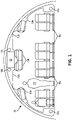
- FIG. 1 is a schematic sectional view of an interior of an aircraft 100 with an adjustable lighting system.
- the aircraft can include cabin lighting 102a-b, passenger lighting 104a-c, and pathway lighting 106a-b.
- the adjustable lighting system can include a processing device 120 communicatively coupled to sensors 130a-d.
- the sensors 130a-d can determine location data about a movable object 110 (e.g., a crew member) and transmit the location data to the processing device 120.
- the processing device 120 can use the location data to determine the location of the movable object 110.
- the processing device 120 can further adjust any combination of cabin lighting 102a-b, passenger lighting 104a-c, and pathway lighting 106a-b based on the location of the movable object 110.
- a remote device can be assigned an initial location, and a current location can be calculated based on movement of the device.
- accelerometers could be placed both on the remote device and the structure of the aircraft and used, along with the initial location, to determine the current location.
- the lighting in a section of the aircraft can be adjusted differently based on the movable object being a crew member or a passenger.
- passenger lighting can be activated based on the nearby presence of a trolley cart while pathway lighting can be activated for a nearby passenger.
- lighting can be adjusted in a section of the aircraft based on the current location of the movable object while lighting in an additional section of the aircraft can be adjusted based on the past location of the movable object.
Landscapes
- Engineering & Computer Science (AREA)
- Mechanical Engineering (AREA)
- Aviation & Aerospace Engineering (AREA)
- General Engineering & Computer Science (AREA)
- Circuit Arrangement For Electric Light Sources In General (AREA)
Description
- The present invention relates generally to a lighting system and, more particularly to a lighting system for an aircraft that can be adjusted based on the location of a movable object.
- An aircraft can include lighting in the interior of the cabin. The lighting can include overhead lighting for passengers (e.g., reading lighting), pathway lighting, and signage (e.g., lavatory signs and exit signs). In some examples, the lighting may be adjustable between on and off. In additional or alternative examples, the brightness, color, and/or angle of the lighting can be adjusted. Different lighting conditions may be desired, for example, based on the time of day and activity of a passenger or crew member. For example, the document
US2009112407 A1 discloses a lighting system for an aircraft receiving data from various sensors such as a lavatory occupant sensor, a seatbelt sensor or a seat occupied sensor. - The terms "invention," "the invention," "this invention" and "the present invention" used in this patent are intended to refer broadly to all of the subject matter of this patent and the patent claims below. Statements containing these terms should be understood not to limit the subject matter described herein or to limit the meaning or scope of the patent claims below. Embodiments of the invention covered by this patent are defined by the claims below, not this summary. This summary is a high-level overview of various aspects of the invention and introduces some of the concepts that are further described in the Detailed Description section below. This summary is not intended to identify key or essential features of the claimed subject matter, nor is it intended to be used in isolation to determine the scope of the claimed subject matter. The subject matter should be understood by reference to appropriate portions of the entire specification of this patent, any or all drawings, and each claim.
- Disclosed herein is an aircraft lighting system that includes a processing device for adjusting or controlling one or more lighting units based on the location of a movable object. In some aspects, the lighting system includes one or more sensors positionable in the aircraft for determining the location data of the movable object relative to the aircraft. The processing device can be communicatively coupled to at least one sensor of the one or more sensors for receiving the location data from the at least one sensor. Furthermore, the lighting system also includes a remote device affixed to or held by the movable object. The processing device can be communicatively coupled to the remote device for receiving the location data from the remote device. In addition, the lighting system includes one or more sensors that communicate with the remote device to determine location data about the movable object. The processing device can determine a location of the movable object based on the location data and adjust one or more lighting units based on the determined location.
- In addition, the one or more sensors each include a communication circuit for communicating a signal between one or more sensors and a remote device that can be coupled to the movable object.
- According to the invention, the system further includes the remote device for transmitting the signal with type data about a type of the movable object. The system can additionally adjust the lighting in the section of the aircraft based on the type data.
- In some examples, the type of the movable object can include at least one of a passenger, a crew member, a trolley cart, or a robot.
- In some examples, the signal is a response signal. Furthermore, each communication circuit can be configured to transmit a request signal to the remote device for powering the remote device such that the remote device transmits the response signal.
- In some examples, the request signal can instruct the remote device to transmit the response signal at a first time. The sensors can further determine the location data based on a comparison of the first time and a second time at which the response signal was received by the one or more sensors.
- In some examples, adjusting the lighting in the section of the aircraft can include activating a set of overhead lights above passenger seats nearest to the location of the movable object.
- In some examples, adjusting the lighting in the section of the aircraft can include activating signage in a part of the aircraft nearest the location of the movable object.
- In some examples, the location can be a current location and the system can further include a storage device for storing a past location of the movable object. The processing device can further be configured to adjust additional lighting in an additional section of the aircraft based on the current location and the past location.
- In some examples, at least one sensor of the one or more sensors can be a proximity sensor for detecting the location of the movable object by detecting that the movable object is proximate to the proximity sensor. In other examples, at least one sensor of the one or more sensors can be a camera.
- Also disclosed is a method that includes receiving a signal from a remote device coupled to a movable object in an aircraft. The method can further include determining a location of the movable object based on the signal. And, the method can include adjusting lighting in one or more sections of the aircraft based on the location of the movable object.
- In some examples, the signal can include type data about a type of the movable object. Adjusting the lighting in the section of the aircraft can further be based on the type data.
- In some examples, the signal can be a response signal. The method can further include transmitting a request signal to the remote device that can power the remote device such that the remote device can transmit the response signal.
- In some examples, the request signal can instruct the remote device to transmit a response signal at a first time. The method can further include observing a second time at which the response signal is received by a receiver. And, the location of the movable object can be determined based on a difference between the first time and the second time.
- In some examples, receiving the signal from the remote device can include receiving the signal by more than one receiver. And, determining the location of the movable object can include comparing when the signal was received at each sensor.
- In some examples, adjusting lighting in one or more sections of the aircraft can include activating at least one of a set of overhead lights above passenger seats nearest the location of the movable object, a sign nearest the location of the movable object, or pathway lights nearest the location of the movable object.
- In some examples, the method can further include storing the location of the movable object. And, adjusting lighting in one or more sections of the aircraft can be further based on a past location of the movable object.
- Also disclosed is a non-transitory computer-readable medium having instructions stored thereon that can be executable by a processing device to perform operations. The operations can include determining a location of a movable object in an aircraft. And, the operations can further include adjusting lighting in one or more sections of the aircraft based on the location of the movable object.
- In some examples, the movable object can be coupled to a radio-frequency identification tag. And, determining the location of the movable object can include receiving a signal from the radio-frequency identification tag.
- In some examples, the signal can include type data about the type of movable object and the type data can be used to adjust the lighting in the section of the aircraft.
-
-
FIG. 1 is a schematic sectional view of an interior of an aircraft with an adjustable lighting system according to an example. -
FIG. 2 is a block diagram of an adjustable lighting system and a remote device coupled to a movable object according to an example. -
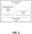
FIG. 3 is a block diagram of a device that can be coupled to a movable object according to an example. -
FIG. 4 is a flow chart of a process for adjusting the lighting based on the location of the movable object. - The subject matter of embodiments of the present invention is described here with specificity to meet statutory requirements, but this description is not necessarily intended to limit the scope of the claims. The claimed subject matter may be embodied in other ways, may include different elements or steps, and may be used in conjunction with other existing or future technologies. This description should not be interpreted as implying any particular order or arrangement among or between various steps or elements except when the order of individual steps or arrangement of elements is explicitly described.
- Disclosed is a lighting system that is adjustable based on a location of a movable object. An adjustable lighting system in an aircraft can detect the location of a movable object within the aircraft and can adjust lighting in one or more sections of the aircraft based on the location of the movable object. For example, as a flight attendant with a trolley cart approaches a passenger, the adjustable lighting system can detect the movable object (e.g., the flight attendant and/or the trolley cart) and adjust the lights above or proximate the passenger accordingly.
- Although the lighting system can be used with passenger aircrafts, the lighting system is by no means limited to aircrafts. Rather, the lighting system may be used in any vehicle or other lighting environment as desired.
- In some aspects, the adjustable lighting system can adjust or control any lighting in an aircraft including, but not limited to, overhead lighting, galley lighting, crew rest lighting, passenger lighting, lavatory lighting, and pathway lighting. In additional or alternative aspects, the lighting can include a sign (e.g., an exit sign or a lavatory occupancy sign). For example, the adjustable lighting system can detect a trolley cart moving through the aircraft and activate the lavatory occupancy sign to discourage passengers from accessing the lavatory while the trolley is in the aisle. In some aspects, the adjustable lighting system can activate or deactivate a light, brighten or dim the light, change the color of the light, and/or change the direction the light is facing. In some examples, the adjustable lighting system can monitor crew members serving food and brighten the lighting above only those passengers that have been served.
- In some aspects, the lighting can be controlled by instructing the lighting to perform a specific lighting scenario. A lighting scenario can include a set of instructions for a lighting unit including whether to be activated or deactivated, the brightness of the light, the color of the light, and/or the direction the light is facing. In some examples, the lighting scenario can be for a section of lighting units and include sub-scenarios with instructions for specific lighting units (.e.g., scenario A includes scenario A.1 for lighting unit 1, A.2 for lighting unit 2, etc.). In some examples, the lighting units can include embedded memory with the lighting scenarios or sub-scenarios stored therein such that a processing device can send instructions to run a specific lighting scenario. This configuration limits the bandwidth of the signal to be sent to each lighting unit. In additional or alternative examples, the processing device can maintain a database of lighting scenarios and when the lighting scenario is appropriate for individual lighting units. The processing device can further store a serial number or IP address for each lighting unit and each lighting unit can include memory for storing the lighting unit's own serial number or IP address. Each lighting unit will then play the scenario corresponding to its serial number or IP address.
- The adjustable lighting system can include a processing device communicatively coupled to a location system. In some aspects, the location system includes one or more sensors. The one or more sensors can be stationary or mobile devices. The adjustable lighting system can include enough sensors to provide sufficient resolution of the cabin in relation to the spatial resolution of the lighting scenarios. For example, if a lighting scenario includes increasing the lighting intensity at one specific row of seats, then the number of sensors and positioning of the sensors must be sufficient to ensure spatial resolution of at least one row.
- The one or more sensors can determine location data about the movable object and transmit the data to the processing device. The one or more sensors can include a wireless or wired connection to the processing device for communicating the location data. The processing device can use the location data to determine the location of the movable object. In some aspects, the one or more sensors can include proximity sensors and the location data can include notification that the movable object is proximate a specific proximity sensor. In additional or alternative aspects, the one or more sensors can include cameras for capturing images of the movable object that the processing device can use to determine the location of the movable object.
- In addition, the location system includes a remote device that can be coupled to the movable object. The remote device can determine location data about the movable object or be used by the location system to determine location data about the movable object. For example, the one or more sensors can include receivers for receiving signals from the remote device. The remote device can include a passive communication circuit (e.g., a radio-frequency identification ("RFID") tag) for transmitting a signal that can be received by the one or more sensors to determine location data. In some examples, the location data can include the time the signal was received at each sensor and the processing device can determine the location of the movable object based on comparing the time the signal was received at each sensor. In additional or alternative examples, the remote device can determine location data and transmit the location data to a sensor.
- In additional or alternative aspects, the sensors can include a communication circuit for transmitting signals from the sensors to the remote device. In some examples, the sensors can include a passive communication circuit (e.g., an RFID tag) for transmitting a signal in response to a signal from the remote device. In additional or alternative examples, the signal transmitted by the sensors can be used by the remote device to determine the location data, and the remote device can transmit the location data to the processing device. In some aspects, at least one sensor can be movable and can provide a signal to the location system for updating the sensor's location. In additional or alternative aspects, one of the sensors can determine changes in the sensor's location based on the detection of nearby sensors and provide location data to the location system or a processing device. In some examples, at least one of the sensors can be a remote device for coupling to a movable object and can be used to determine the location of the movable object.
- In some aspects, the movable object can be a person or a thing. For example, the movable object can be a passenger, a crew member, a trolley cart, a robot, a crew member's handheld device, a passenger's handheld device, a badge, or a ticket. In additional or alternative aspects, the adjustable lighting system can further adjust the lights based on the type of movable object. In some aspects, the sensors can include receivers, emitters, transmitters, transceivers, motion detectors, proximity detectors, light detectors, or cameras. In additional or alternative aspects, the sensors can be passive devices such as RFID tags or spatial landmarks for recognition by the location system. In some aspects, the remote device can include or be a part of a personal computer, mobile phone, RFID tag, a Near Field Communication ("NFC") circuit, Bluetooth circuit, or wireless transceiver.
- In some aspects, the adjustable lighting system can further include a scenario programming platform. The scenario programming platform can provide a user friendly display for adjusting the lighting scenarios and for checking the lighting. The platform can also be used to display the location of particular movable objects, the ID of remote devices, sensors, and lighting units, and provide a virtual mock-up of the locations of the sensors. In some aspects, the adjustable lighting system can include a maintenance mode for checking the function of the lighting units. While in maintenance mode, a light acquisition device can identify differences in lighting provided by lighting units and indicate adjustments that can be made to provide uniform lighting. For example, different lighting units can develop different brightness and color due to aging, but the adjustable lighting system can provide adjustments to individual lighting units to ensure uniform lighting.
- These illustrative examples are given to introduce the reader to the general subject matter discussed here and are not intended to limit the scope of the disclosed concepts. The following sections describe various additional features and examples with reference to the drawings in which like numerals indicate like elements, and directional descriptions are used to describe the illustrative aspects but, like the illustrative aspects, should not be used to limit the present invention.
-
FIG. 1 is a schematic sectional view of an interior of anaircraft 100 with an adjustable lighting system. The aircraft can includecabin lighting 102a-b,passenger lighting 104a-c, andpathway lighting 106a-b. The adjustable lighting system can include aprocessing device 120 communicatively coupled tosensors 130a-d. Thesensors 130a-d can determine location data about a movable object 110 (e.g., a crew member) and transmit the location data to theprocessing device 120. Theprocessing device 120 can use the location data to determine the location of themovable object 110. Theprocessing device 120 can further adjust any combination ofcabin lighting 102a-b,passenger lighting 104a-c, andpathway lighting 106a-b based on the location of themovable object 110. - For example,
processing device 120 can determine themovable object 110 is in the left pathway (as depicted inFIG. 1 ) and activateoverhead lighting 102a and/orpathway lighting 106a. In additional or alternative examples, theprocessing device 120 can determine themovable object 110 is in the left pathway and dimoverhead lighting 102b and/orpathway lighting 106b. In additional or alternative examples, theprocessing device 120 can adjust the color, intensity, and angle of lighting inaircraft 100 based on the location of themovable object 110. - In some aspects,
sensors 130a-d include proximity sensors that can detect the presence of a movable object. In some examples, a proximity sensor can include a processing device and can adjust lighting in one or more sections of the aircraft proximate the proximity sensor based on detecting themovable object 110. AlthoughFIG. 1 depictsprocessing device 120 as separate from the sensors, in some examples each sensor can include a processing device that can adjust lighting in one or more sections of the aircraft associated with the sensor. - In addition, a remote device can be coupled to the
movable object 110. The remote device can include a communication circuit for transmitting a signal receivable bysensors 130a-d. The sensors can determine location data based on the signal received. In some examples, the communication circuit can be an RFID tag, a NFC circuit, a Bluetooth circuit, or any wireless transceiver. In additional or alternative examples, the sensors can transmit a request signal to the communication circuit requesting a response signal. In some additional examples, the request signal can instruct the communication circuit to send the response signal at a specific time. The sensors can record the time the response signal is received at the sensor and compare the transmission time and the received time to determine location data. - Although
FIG. 1 depicts themovable object 110 as a person, a movable object can be any person or thing that can move or be moved relative theaircraft 100. For example, a movable object could include a trolley cart, a passenger, a crew member, luggage, a book, a tray table, or a ticket. Furthermore,FIG. 1 depicts foursensors 130a-d communicatively coupled to oneprocessing device 120 but an adjustable lighting system can include any number of sensors communicatively coupled to any number of processing devices, and these sensors can be located anywhere within the aircraft. In some aspects, sensors can be passive RFID tags positioned throughout an aircraft to create a grid. In some examples, a remote device can acquire location data from communication or recognition of nearby sensors. The remote device can transmit the location data to a processing device for determining the location of the movable object. The remote device can further transmit a unique ID to the processing device such that the processing device can adjust lighting in the aircraft for one or more remote devices and adjust the lighting based on the ID. In additional or alternative examples, the remote device can transmit a signal and ID to nearby sensors, and each sensor can transmit the signal and ID to the processing device. - In some aspects, a remote device can be assigned an initial location, and a current location can be calculated based on movement of the device. For example, accelerometers could be placed both on the remote device and the structure of the aircraft and used, along with the initial location, to determine the current location.
- In some examples, each section or sections of lighting can be communicatively coupled to a dedicated processing device that is communicatively coupled to one or more sensors. The
overhead lighting 102a-b,passenger lighting 104a-c, andpathway lighting 106a-b are only examples of some of the lighting that can be adjusted by an adjustable lighting system. In additional or alternative examples, an adjustable lighting system can control or adjust signs (e.g., an exit sign or a lavatory occupancy sign) or any other lighting located in theaircraft 100. -
FIG. 2 is a block diagram of anadjustable lighting system 200 and aremote device 210 coupled to amovable object 110. Theadjustable lighting system 200 includes aprocessing device 120 communicatively coupled tolighting 202a-d andsensors 230a-b. Thesensors 230a-b are each communicatively coupled to anantenna 232a-b. In some aspects, thesensors 230a-b can use theantennas 232a-b to receive a signal transmit by theremote device 210. The sensors can determine location data about themovable object 110 from the signal and transmit the location data to theprocessing device 120. For example, the signal can be sent at a predetermined time and thesensors 230a-b can each record the time the signal is received such that the time it took the signal to reach eachsensor 230a-b can be determined. - In some aspects, the signal transmit by the
remote device 210 can include information. For example, the signal can include information about themovable object 110 such as the movable object's type (e.g., a passenger, a trolley cart, or a robot). In additional or alternative examples, the signal can include information about the location of themovable object 110. - The
processing device 120 can include any number of processors configured for executing program code stored in thememory 222. Examples of theprocessing device 120 can include a microprocessor, an application-specific integrated circuit ("ASIC"), a field-programmable gate array ("FPGA"), or other suitable processor. In some aspects, theprocessing device 120 can be a dedicated processing device used for adjusting a section or sections oflighting 202a-d based on a location of themovable object 110. In other aspects, theprocessing device 120 can perform additional functions such as controlling overhead fans or transmitting passenger requests to a flight attendant. - The
processing device 120 can include (or be communicatively coupled with) a non-transitory computer-readable memory 222. Thememory 222 can include one or more memory devices that can store program instructions. The program instructions can include, for example, a lighting adjustment engine that is executable by theprocessing device 120 to perform certain operations described herein. - The operations can include determining a location of the
movable object 110 in an aircraft. In some aspects, the movable object can be coupled to an RFID tag and determining the location of themovable object 110 can include receiving a signal from the RFID tag. The operations can further include adjusting thelighting 202a-d in one or more sections of the aircraft based on the location of themovable object 110. In additional or alternative aspects, a signal from theremote device 210 can include data about the type of movable object to which theremote device 210 is coupled. Adjusting thelighting 202a-d in the one or more sections of the aircraft can further be based on the type ofmovable object 110. The type can be a general category, for example, classifying themovable object 110 as a person or a thing. Additionally or alternatively, the type can be more specific, for example, describing themovable object 110 as a child passenger, a special needs passenger, a crew member, or a trolley cart. - The
memory 222 can also store past locations of themovable object 110. In some aspects, theprocessing device 120 can adjust thelighting 202a-d in one or more sections of the aircraft based both on the current location of themovable object 110 and one or more past locations of themovable object 110. For example, theprocessing device 120 can determine the current location of themovable object 110 is different than its past location, brighten thelighting 202a-d in a section of the aircraft near the current location and dim thelighting 202a-d in a section of the aircraft near the past location. In additional or alternative aspects, theprocessing device 120 can determine the direction themovable object 110 is moving and adjustlighting 202a-d in a section of the aircraft further based on the direction themovable object 110 is travelling. In additional or alternative aspects, theprocessing device 120 can estimate a future location of themovable object 110 based on its current location and past location and adjustlighting 202a-d in a section of the aircraft further based on the future location. For example, theprocessing device 120 can detect the movable object 110 (e.g., a passenger) moving towards the rear of the plane and estimate that themovable object 110 is headed to the lavatory. Theprocessing device 120 can activate the pathway lighting to the lavatory, brighten the lavatory occupancy sign, and activate the lavatory lighting based on the estimate. - Although
FIG. 2 depicts one example of anadjustable lighting system 200, other implementations are possible. In some examples, theprocessing device 120 is embedded within thesensors 230a-b orlighting 202a-d. In additional or alternative examples, theprocessing device 120,remote device 210,lighting 202a-d, andsensors 230a-d can each include (or be communicatively coupled to) a processing device, a communication circuit, a storage device, a power supply, or an antenna. For example, eachlighting 202a-d can include a an embedded memory for storing identification information and lighting scenarios. In additional or alternative aspects, theremote device 210 can include an antenna for communicatively coupling directly to theprocessing device 120. In additional or alternative aspects, theremote device 210 can determine location data about themovable object 110 and transmit the location data directly to theprocessing device 120. For example, theremote device 210 can receive signals fromsensors 230a-b and use the received signals to determine the location data. -
FIG. 3 is a block diagram of aremote device 210 that can be coupled to a movable object in an aircraft. Theremote device 210 can include acommunication circuit 312,memory 314, and apower supply 316. Thecommunication circuit 312 can be powered by thepower supply 316 to transmit a signal receivable by one or more sensors in the aircraft. Thecommunication circuit 312 can further be communicatively coupled to thememory 314 such that data stored inmemory 314 can be transmitted as part of the signal. In some aspects, the data can include information about the movable object to which theremote device 210 can be coupled. In additional or alternative aspects, signals received by thecommunication circuit 312 can instruct that data be written to thememory 314. For example, theremote device 210 can further include a processing device that receives location data from signals received at thecommunication circuit 312 and uses the location data to determine a location of the movable object and store the location data tomemory 314. In additional or alternative aspects, theremote device 210 can be a sensor and can communicatively coupled to an antenna for communicating directly with a processing device of an adjustable lighting system. - The
remote device 210 can be an size or shape. The remote device can be coupled to the movable object by any means. In some examples, the remote device can be fastened to a movable object using any suitable fastener, including but not limited to a screw, bolt, rivet, welding, or adhesive. In additional or alternative examples, theremote device 210 may be located in a pocket, badge, or item carried or worn by the movable object. - Although the
remote device 210 inFIG. 3 is illustrated as including apower supply 316, in some aspects theremote device 210 can be powered by signals received by thecommunication circuit 312. For example, thecommunication circuit 312 can include an RFID tag or an NFC circuit that are powered by received signals. In additional or alternative aspects, a remote device consists of only the communication circuit. -
FIG. 4 is a flow chart of an exemplary process for adjusting the lighting in an aircraft based on the location of a movable object. The process can improve the safety and comfort of the aircraft by providing appropriate lighting. For example, the process can increase the lighting around passengers moving through the cabin and dim the lighting in areas of the cabin where passengers are sleeping. The process can also improve the energy efficiency of the aircraft by optimizing the use of the lighting based on the location of the movable object. - In
block 402, a signal is received from a remote device coupled to a movable object in an aircraft. In some aspects, the signal received from the remote device is a response signal in response to a request signal transmit by a sensor. In additional or alternative aspects, the request signal can power the remote device and send instructions about when to send the response signal and what additional data to include in the response signal. The remote device can include a communication circuit that uses any wireless communication protocol including RFID, NFC, and Bluetooth. In some examples, the remote device is a badge worn by a crew member. In additional or alternative examples, the remote device is fastened to a trolley cart. - In
block 404, a location of the movable object is determined based on the signal. In some aspects, determining the location of the movable object can be based on comparing when the signal was received at more than one sensor. In additional or alternative aspects, the request signal can instruct the remote device to transmit the response signal at a specific time. Determining the location of the movable object can include comparing the time at which the response signal was transmitted and the time the response signal was received at a sensor. In some aspects, the signal can include images of the movable object and the location can be determined using image processing. - In
block 406, lighting in one or more sections of the aircraft is adjusted based on the location of the movable object. In some aspects, adjusting the lighting in the section of the aircraft can include activating, deactivating, brightening, dimming, changing the color, and/or changing the angle of lighting. As discussed above, the lighting can include cabin lights, overhead passenger lights, pathway lights, lavatory lights, galley lights, crew rest lights, signage, etc. In additional or alternative aspects, adjusting the lighting in the section of the aircraft can include activating lighting nearest the location of the movable object. In some aspects, the lighting can be adjusted based on additional information such as the type of the movable object and past locations of the movable object. For example, the lighting in a section of the aircraft can be adjusted differently based on the movable object being a crew member or a passenger. In additional or alternative examples, passenger lighting can be activated based on the nearby presence of a trolley cart while pathway lighting can be activated for a nearby passenger. In additional or alternative examples, lighting can be adjusted in a section of the aircraft based on the current location of the movable object while lighting in an additional section of the aircraft can be adjusted based on the past location of the movable object. - Although the process in
FIG. 4 describes determining a location of the movable object based on signals received from a remote device, other implementations are possible. In some aspects, a location of the movable object can be determined based on proximity sensors detecting the movable object. In additional aspects, a location of the movable object can be determined based on image processing of images taken by a camera. Furthermore, the adjustable light system and the processes described herein can be implemented in any lighting environment including vehicles such as buses, trains, and ships. - Different arrangements of the components depicted in the drawings or described above, as well as components and steps not shown or described are possible. Similarly, some features and sub-combinations are useful and may be employed without reference to other features and sub-combinations. Embodiments of the invention have been described for illustrative and not restrictive purposes, and alternative embodiments will become apparent to readers of this patent. Accordingly, the present invention is not limited to the embodiments described above or depicted in the drawings, and various embodiments and modifications may be made without departing from the scope of the claims below.
Claims (15)
- A lighting system for adjusting one or more lighting units (104a-c, 202a-d) in a vehicle based on the location of a moveable object (110) within said vehicle (100) comprising:one or more sensors (130a-d, 202a-b) positionable in said vehicle (100) for determining location data of a movable object (110) relative to the vehicle (100);a remote device (210) which can be coupled to the movable object (110), wherein the one or more sensors (130a-d, 202a-b) each comprise a communication circuit for communicating a signal between the one or more sensors (130a-d, 202a0b) and the remote device (210) anda processing device (120) communicatively coupled to at least one sensor (130a-d, 202a-b) of the one or more sensors (130a-d, 202a-b) for receiving the location data from the at least one sensor (130a-d, 202a-b), determining a location of the movable object (110) based on the location data, and adjusting lighting in one or more sections of the vehicle (100) based on the location of the movable object (110);characterised in that;the remote device (210) is configured to transmit the signal with type data about a type of the movable object (110), andwherein adjusting the lighting in the one or more sections of the vehicle (100) is further based on the type data.
- The system of claim 1, wherein the type of the movable object (110) is at least one of a passenger, a crew member, a trolley cart, or a robot.
- The system of claim 1 or 2, wherein adjusting the lighting in the one or more sections of the vehicle (100) comprises activating a set of overhead lights (104a-c) above passenger seats nearest to the location of the movable object (110).
- The system of any of the preceding claims, wherein adjusting the lighting in the one or more sections of the vehicle (100) comprises activating signage in a part of the vehicle (100) nearest the location of the movable object (110).
- The system of any of the preceding claims, wherein the location is a current location and the system further comprises a storage device for storing a past location of the movable object, and wherein the processing device is further for adjusting additional lighting in an additional section of the vehicle based on at least one of the current location and the past location.
- The system of any of the preceding claims, wherein at least one sensor of the one or more sensors (130a-d, 202a-b) is a proximity sensor for detecting the location of the movable object (110) by detecting the movable object (110) is proximate to the proximity sensor.
- The system of any of the preceding claims, wherein the remote device (210) comprises a communication circuit (312) for transmitting a signal receivable by the one or more sensors (130a-d).
- The system of claim 7, wherein the remote device (210) is powered by signals received by the communication circuit (312) of the remote device (210).
- A method for adjusting one or more lighting units (104a-c, 202a-d) in a vehicle based on the location of a moveable object (110) within said vehicle (100) by a lighting system as defined in any of the claims 1 to 8 comprising:receiving a signal from a remote device (210) coupled to a movable object (110) in the vehicle (100) ;determining a location of the movable object (110) based on the signal; and adjusting lighting in one or more sections of the vehicle (100) based on the location of the movable object (110);characterized in that;the signal includes type data about a type of the movable object (110), and the method further comprises adjusting the lighting in the one or more sections of the vehicle (100) is further based on the type data.
- The method of claim 9, wherein the signal is a response signal and the method further comprises transmitting a request signal to the remote device (210) that powers the remote device (210) such that the remote device (210) transmits the response signal.
- The method of claim 10, wherein the request signal instructs the remote device (210) to transmit the response signal at a first time, wherein the method further comprises observing a second time at which the response signal is received by a receiver, and wherein determining the location of the movable object (110) is further based on a difference between the first time and the second time.
- The method of any of claims 9 to 11, wherein receiving the signal from the remote device comprises receiving the signal by more than one receiver, and wherein determining the location of the movable object comprises comparing when the signal was received at each sensor.
- The method of any of the claims 9 to 12, wherein adjusting lighting in the one or more sections of the vehicle (100) comprises activating at least one of a set of overhead lights above passenger seats nearest the location of the movable object (110), a sign nearest the location of the movable object (110), or pathway lights nearest the location of the movable object (110).
- The method of claim 13, further comprising storing the location of the movable object (110), and adjusting lighting in the one or more sections of the vehicle (100) is based on a past location of the movable object (110).
- A non-transitory computer-readable medium having instructions stored thereon that are executable by a processing device (120) to cause a lighting system as defined in claims 1 to 8 to perform operations as defined by the method of any of the claims 9 to 14.
Applications Claiming Priority (2)
| Application Number | Priority Date | Filing Date | Title |
|---|---|---|---|
| US201562166409P | 2015-05-26 | 2015-05-26 | |
| PCT/US2016/034341 WO2016191560A1 (en) | 2015-05-26 | 2016-05-26 | Adjustable lighting in an aircraft based on location of movable object |
Publications (2)
| Publication Number | Publication Date |
|---|---|
| EP3305033A1 EP3305033A1 (en) | 2018-04-11 |
| EP3305033B1 true EP3305033B1 (en) | 2022-06-29 |
Family
ID=56119779
Family Applications (1)
| Application Number | Title | Priority Date | Filing Date |
|---|---|---|---|
| EP16728800.0A Active EP3305033B1 (en) | 2015-05-26 | 2016-05-26 | Adjustable lighting in a vehicle based on location of movable object |
Country Status (4)
| Country | Link |
|---|---|
| US (1) | US10129954B2 (en) |
| EP (1) | EP3305033B1 (en) |
| CN (1) | CN107836138A (en) |
| WO (1) | WO2016191560A1 (en) |
Families Citing this family (21)
| Publication number | Priority date | Publication date | Assignee | Title |
|---|---|---|---|---|
| JP6725899B2 (en) * | 2015-05-22 | 2020-07-22 | シグニファイ ホールディング ビー ヴィSignify Holding B.V. | Lighting control based on orientation and auxiliary device input |
| US10940790B1 (en) | 2015-12-01 | 2021-03-09 | Apple Inc. | System and method for adjustable lighting based on occupant and object identification in a vehicle |
| US9725033B1 (en) * | 2016-03-11 | 2017-08-08 | B/E Aerospace, Inc. | Method and system for displaying a moveable lighting scene in a passenger cabin |
| CN106527488A (en) * | 2016-12-31 | 2017-03-22 | 上海量明科技发展有限公司 | Automatic tracking illumination unmanned aerial vehicle and system, and realization method thereof |
| EP3459860B1 (en) * | 2017-09-22 | 2021-01-06 | Goodrich Lighting Systems GmbH | Aircraft cabin lighting arrangement for illuminating a common space of an aircraft, aircraft comprising the same, and method of operating an aircraft cabin lighting arrangement |
| US10449895B2 (en) * | 2018-03-20 | 2019-10-22 | Rockwell Collins, Inc. | Object tracking illumination system |
| GB2575058B (en) | 2018-06-27 | 2022-11-09 | Safran Seats Gb Ltd | An aircraft suite |
| JP7046734B2 (en) * | 2018-06-27 | 2022-04-04 | 矢崎総業株式会社 | Car interior lighting system |
| DE102019108490A1 (en) * | 2019-04-01 | 2020-10-01 | Recaro Aircraft Seating Gmbh & Co. Kg | Aircraft seat assembly |
| US20200367332A1 (en) * | 2019-05-17 | 2020-11-19 | Goodrich Corporation | Smart night-lighting of aircraft cabin |
| GB2590406B (en) | 2019-12-16 | 2024-04-03 | Safran Seats Gb Ltd | An aircraft passenger suite |
| CA3102737A1 (en) * | 2019-12-18 | 2021-06-18 | Bombardier Inc. | Lighting system for a vehicle cabin |
| US11628765B2 (en) * | 2020-07-30 | 2023-04-18 | The Boeing Company | System and method for illuminating a moving object within an enclosed space |
| US11919644B2 (en) * | 2021-01-27 | 2024-03-05 | B/E Aerospace, Inc. | Galley equipment hazards alert |
| US11866174B2 (en) * | 2021-02-17 | 2024-01-09 | Gulfstream Aerospace Corporation | Occupant tracking lighting system |
| EP4113492A1 (en) | 2021-06-28 | 2023-01-04 | B/E Aerospace, Inc. | Adjustable display |
| US11818821B2 (en) | 2021-08-12 | 2023-11-14 | Goodrich Lighting Systems, Inc. | Autonomous light systems and methods for operating autonomous light systems |
| EP4180330A1 (en) * | 2021-11-15 | 2023-05-17 | Goodrich Corporation | Systems and methods for touchless passenger light control |
| US12376213B2 (en) | 2021-11-15 | 2025-07-29 | Goodrich Corporation | Systems and methods for touchless passenger light control |
| CN116166047A (en) * | 2023-02-24 | 2023-05-26 | 浙江华云电力企业服务有限公司 | Unmanned aerial vehicle automatic following method, system, terminal and medium |
| US12553734B2 (en) * | 2023-06-02 | 2026-02-17 | Pioneer Corporation | Light emitting device, control method for light emitting device, and medium |
Family Cites Families (13)
| Publication number | Priority date | Publication date | Assignee | Title |
|---|---|---|---|---|
| ATE438825T1 (en) * | 2002-10-09 | 2009-08-15 | Manfred Kluth | LIGHTING DEVICE WITH SENSORS |
| US7413327B2 (en) | 2006-04-10 | 2008-08-19 | The Boeing Company | Vehicle lighting fixture |
| US20090112407A1 (en) * | 2007-10-29 | 2009-04-30 | The Boeing Company | System and Method for Communication by Architecture |
| DE102008033733B4 (en) * | 2008-07-17 | 2020-06-18 | Airbus Operations Gmbh | System and method for operating a variety of service positions |
| JP2012226993A (en) * | 2011-04-20 | 2012-11-15 | Panasonic Corp | Illumination system |
| US20140103814A1 (en) * | 2012-03-15 | 2014-04-17 | General Electric Company | Communication system for adaptive lighting control |
| FR3000026B1 (en) * | 2012-12-21 | 2016-12-09 | Airbus | AIRCRAFT COMPRISING A PILOTAGE STATION WITH A VISION SURFACE FOR AT LEAST PARTIALLY VIRTUAL DRIVING |
| US8655593B1 (en) * | 2013-03-12 | 2014-02-18 | United Parcel Service Of America, Inc. | Concepts for defining travel paths in parking areas |
| DE102013207062A1 (en) * | 2013-04-18 | 2014-10-23 | Airbus Operations Gmbh | Vehicle cabin arrangement with a lighting device |
| US9296333B2 (en) * | 2013-05-14 | 2016-03-29 | Zodiac Aerotechnics | Lighting device of an aircraft, system, passenger service unit, method of operating a lighting device |
| US9308920B2 (en) * | 2014-02-05 | 2016-04-12 | GM Global Technology Operations LLC | Systems and methods of automating driver actions in a vehicle |
| US20150251594A1 (en) * | 2014-03-07 | 2015-09-10 | Idd Aerospace Corporation | Aircraft cabin light system |
| US10137830B2 (en) * | 2014-12-02 | 2018-11-27 | Lenovo (Singapore) Pte. Ltd. | Self-adjusting lighting based on viewing location |
-
2016
- 2016-05-26 CN CN201680041109.7A patent/CN107836138A/en active Pending
- 2016-05-26 US US15/165,764 patent/US10129954B2/en active Active
- 2016-05-26 WO PCT/US2016/034341 patent/WO2016191560A1/en not_active Ceased
- 2016-05-26 EP EP16728800.0A patent/EP3305033B1/en active Active
Also Published As
| Publication number | Publication date |
|---|---|
| US10129954B2 (en) | 2018-11-13 |
| US20160353551A1 (en) | 2016-12-01 |
| WO2016191560A1 (en) | 2016-12-01 |
| EP3305033A1 (en) | 2018-04-11 |
| CN107836138A (en) | 2018-03-23 |
Similar Documents
| Publication | Publication Date | Title |
|---|---|---|
| US10129954B2 (en) | Adjustable lighting in an aircraft based on location of movable object | |
| EP3543121B1 (en) | Object tracking illumination system | |
| US20230186182A1 (en) | Vehicle ride sharing system and method using smart modules | |
| EP3450315B1 (en) | In-vehicle position detection and configuration of vehicle components | |
| US10043396B2 (en) | Passenger pickup system and method using autonomous shuttle vehicle | |
| EP3395684B1 (en) | Vehicle attendant task management systems and methods | |
| JP7840632B2 (en) | Seat assembly, seat belt fastening system, and method | |
| US20180086464A1 (en) | Electronic baggage stowage system and methods | |
| EP3842288B1 (en) | Lighting system for a vehicle cabin | |
| US20170113801A1 (en) | Cabin monitoring system and cabin of aircraft or spacecraft | |
| US12375875B2 (en) | Passenger location platform | |
| CN106415678A (en) | Method for guiding passengers | |
| CN110316383B (en) | Seat sensor array and controller and seat assembly having the same | |
| US10799026B2 (en) | Systems and methods for arranging seats in a seating area | |
| CN107111805A (en) | Passenger's catering system for passenger vehicles | |
| EP3862275B1 (en) | Boarding guidance system | |
| JP6964669B2 (en) | Luggage monitoring system | |
| KR20170111837A (en) | Boarding management system using beacon for children's school vehicle | |
| WO2017109020A1 (en) | Wireless seat reservation display apparatus | |
| CN111667782B (en) | Mobile body and mobile system | |
| US11544811B2 (en) | Identifying a vehicle using a wearable device | |
| US11136127B2 (en) | Supervision system for an aircraft for monitoring the safe charging of portable electrical devices | |
| KR20170059217A (en) | Terminal for crew location tracking in ships and crew location tracking system using thesame | |
| KR102697522B1 (en) | System for obtaining identity information for an object getting on and off of vehicle and the obtaining method thereof | |
| JP2024079154A (en) | Verification system and verification method |
Legal Events
| Date | Code | Title | Description |
|---|---|---|---|
| STAA | Information on the status of an ep patent application or granted ep patent |
Free format text: STATUS: THE INTERNATIONAL PUBLICATION HAS BEEN MADE |
|
| PUAI | Public reference made under article 153(3) epc to a published international application that has entered the european phase |
Free format text: ORIGINAL CODE: 0009012 |
|
| STAA | Information on the status of an ep patent application or granted ep patent |
Free format text: STATUS: REQUEST FOR EXAMINATION WAS MADE |
|
| 17P | Request for examination filed |
Effective date: 20171221 |
|
| AK | Designated contracting states |
Kind code of ref document: A1 Designated state(s): AL AT BE BG CH CY CZ DE DK EE ES FI FR GB GR HR HU IE IS IT LI LT LU LV MC MK MT NL NO PL PT RO RS SE SI SK SM TR |
|
| AX | Request for extension of the european patent |
Extension state: BA ME |
|
| DAV | Request for validation of the european patent (deleted) | ||
| DAX | Request for extension of the european patent (deleted) | ||
| REG | Reference to a national code |
Ref country code: DE Ref legal event code: R079 Ref document number: 602016073152 Country of ref document: DE Free format text: PREVIOUS MAIN CLASS: H05B0037020000 Ipc: B64D0011000000 |
|
| RIC1 | Information provided on ipc code assigned before grant |
Ipc: B64D 11/00 20060101AFI20210716BHEP Ipc: F21V 23/04 20060101ALI20210716BHEP Ipc: B60Q 3/41 20170101ALI20210716BHEP Ipc: B60Q 3/80 20170101ALI20210716BHEP |
|
| GRAP | Despatch of communication of intention to grant a patent |
Free format text: ORIGINAL CODE: EPIDOSNIGR1 |
|
| STAA | Information on the status of an ep patent application or granted ep patent |
Free format text: STATUS: GRANT OF PATENT IS INTENDED |
|
| INTG | Intention to grant announced |
Effective date: 20211207 |
|
| RAP1 | Party data changed (applicant data changed or rights of an application transferred) |
Owner name: ZODIAC CABIN CONTROLS GMBH |
|
| GRAS | Grant fee paid |
Free format text: ORIGINAL CODE: EPIDOSNIGR3 |
|
| GRAA | (expected) grant |
Free format text: ORIGINAL CODE: 0009210 |
|
| STAA | Information on the status of an ep patent application or granted ep patent |
Free format text: STATUS: THE PATENT HAS BEEN GRANTED |
|
| AK | Designated contracting states |
Kind code of ref document: B1 Designated state(s): AL AT BE BG CH CY CZ DE DK EE ES FI FR GB GR HR HU IE IS IT LI LT LU LV MC MK MT NL NO PL PT RO RS SE SI SK SM TR |
|
| REG | Reference to a national code |
Ref country code: GB Ref legal event code: FG4D |
|
| REG | Reference to a national code |
Ref country code: CH Ref legal event code: EP |
|
| REG | Reference to a national code |
Ref country code: DE Ref legal event code: R096 Ref document number: 602016073152 Country of ref document: DE |
|
| REG | Reference to a national code |
Ref country code: AT Ref legal event code: REF Ref document number: 1501197 Country of ref document: AT Kind code of ref document: T Effective date: 20220715 |
|
| REG | Reference to a national code |
Ref country code: IE Ref legal event code: FG4D |
|
| REG | Reference to a national code |
Ref country code: LT Ref legal event code: MG9D |
|
| PG25 | Lapsed in a contracting state [announced via postgrant information from national office to epo] |
Ref country code: SE Free format text: LAPSE BECAUSE OF FAILURE TO SUBMIT A TRANSLATION OF THE DESCRIPTION OR TO PAY THE FEE WITHIN THE PRESCRIBED TIME-LIMIT Effective date: 20220629 Ref country code: NO Free format text: LAPSE BECAUSE OF FAILURE TO SUBMIT A TRANSLATION OF THE DESCRIPTION OR TO PAY THE FEE WITHIN THE PRESCRIBED TIME-LIMIT Effective date: 20220929 Ref country code: LT Free format text: LAPSE BECAUSE OF FAILURE TO SUBMIT A TRANSLATION OF THE DESCRIPTION OR TO PAY THE FEE WITHIN THE PRESCRIBED TIME-LIMIT Effective date: 20220629 Ref country code: HR Free format text: LAPSE BECAUSE OF FAILURE TO SUBMIT A TRANSLATION OF THE DESCRIPTION OR TO PAY THE FEE WITHIN THE PRESCRIBED TIME-LIMIT Effective date: 20220629 Ref country code: GR Free format text: LAPSE BECAUSE OF FAILURE TO SUBMIT A TRANSLATION OF THE DESCRIPTION OR TO PAY THE FEE WITHIN THE PRESCRIBED TIME-LIMIT Effective date: 20220930 Ref country code: FI Free format text: LAPSE BECAUSE OF FAILURE TO SUBMIT A TRANSLATION OF THE DESCRIPTION OR TO PAY THE FEE WITHIN THE PRESCRIBED TIME-LIMIT Effective date: 20220629 Ref country code: BG Free format text: LAPSE BECAUSE OF FAILURE TO SUBMIT A TRANSLATION OF THE DESCRIPTION OR TO PAY THE FEE WITHIN THE PRESCRIBED TIME-LIMIT Effective date: 20220929 |
|
| REG | Reference to a national code |
Ref country code: NL Ref legal event code: MP Effective date: 20220629 |
|
| REG | Reference to a national code |
Ref country code: AT Ref legal event code: MK05 Ref document number: 1501197 Country of ref document: AT Kind code of ref document: T Effective date: 20220629 |
|
| PG25 | Lapsed in a contracting state [announced via postgrant information from national office to epo] |
Ref country code: RS Free format text: LAPSE BECAUSE OF FAILURE TO SUBMIT A TRANSLATION OF THE DESCRIPTION OR TO PAY THE FEE WITHIN THE PRESCRIBED TIME-LIMIT Effective date: 20220629 Ref country code: LV Free format text: LAPSE BECAUSE OF FAILURE TO SUBMIT A TRANSLATION OF THE DESCRIPTION OR TO PAY THE FEE WITHIN THE PRESCRIBED TIME-LIMIT Effective date: 20220629 |
|
| PG25 | Lapsed in a contracting state [announced via postgrant information from national office to epo] |
Ref country code: NL Free format text: LAPSE BECAUSE OF FAILURE TO SUBMIT A TRANSLATION OF THE DESCRIPTION OR TO PAY THE FEE WITHIN THE PRESCRIBED TIME-LIMIT Effective date: 20220629 |
|
| PG25 | Lapsed in a contracting state [announced via postgrant information from national office to epo] |
Ref country code: SM Free format text: LAPSE BECAUSE OF FAILURE TO SUBMIT A TRANSLATION OF THE DESCRIPTION OR TO PAY THE FEE WITHIN THE PRESCRIBED TIME-LIMIT Effective date: 20220629 Ref country code: SK Free format text: LAPSE BECAUSE OF FAILURE TO SUBMIT A TRANSLATION OF THE DESCRIPTION OR TO PAY THE FEE WITHIN THE PRESCRIBED TIME-LIMIT Effective date: 20220629 Ref country code: RO Free format text: LAPSE BECAUSE OF FAILURE TO SUBMIT A TRANSLATION OF THE DESCRIPTION OR TO PAY THE FEE WITHIN THE PRESCRIBED TIME-LIMIT Effective date: 20220629 Ref country code: PT Free format text: LAPSE BECAUSE OF FAILURE TO SUBMIT A TRANSLATION OF THE DESCRIPTION OR TO PAY THE FEE WITHIN THE PRESCRIBED TIME-LIMIT Effective date: 20221031 Ref country code: ES Free format text: LAPSE BECAUSE OF FAILURE TO SUBMIT A TRANSLATION OF THE DESCRIPTION OR TO PAY THE FEE WITHIN THE PRESCRIBED TIME-LIMIT Effective date: 20220629 Ref country code: EE Free format text: LAPSE BECAUSE OF FAILURE TO SUBMIT A TRANSLATION OF THE DESCRIPTION OR TO PAY THE FEE WITHIN THE PRESCRIBED TIME-LIMIT Effective date: 20220629 Ref country code: AT Free format text: LAPSE BECAUSE OF FAILURE TO SUBMIT A TRANSLATION OF THE DESCRIPTION OR TO PAY THE FEE WITHIN THE PRESCRIBED TIME-LIMIT Effective date: 20220629 |
|
| PG25 | Lapsed in a contracting state [announced via postgrant information from national office to epo] |
Ref country code: PL Free format text: LAPSE BECAUSE OF FAILURE TO SUBMIT A TRANSLATION OF THE DESCRIPTION OR TO PAY THE FEE WITHIN THE PRESCRIBED TIME-LIMIT Effective date: 20220629 Ref country code: IS Free format text: LAPSE BECAUSE OF FAILURE TO SUBMIT A TRANSLATION OF THE DESCRIPTION OR TO PAY THE FEE WITHIN THE PRESCRIBED TIME-LIMIT Effective date: 20221029 |
|
| REG | Reference to a national code |
Ref country code: DE Ref legal event code: R097 Ref document number: 602016073152 Country of ref document: DE |
|
| PG25 | Lapsed in a contracting state [announced via postgrant information from national office to epo] |
Ref country code: AL Free format text: LAPSE BECAUSE OF FAILURE TO SUBMIT A TRANSLATION OF THE DESCRIPTION OR TO PAY THE FEE WITHIN THE PRESCRIBED TIME-LIMIT Effective date: 20220629 |
|
| PG25 | Lapsed in a contracting state [announced via postgrant information from national office to epo] |
Ref country code: DK Free format text: LAPSE BECAUSE OF FAILURE TO SUBMIT A TRANSLATION OF THE DESCRIPTION OR TO PAY THE FEE WITHIN THE PRESCRIBED TIME-LIMIT Effective date: 20220629 Ref country code: CZ Free format text: LAPSE BECAUSE OF FAILURE TO SUBMIT A TRANSLATION OF THE DESCRIPTION OR TO PAY THE FEE WITHIN THE PRESCRIBED TIME-LIMIT Effective date: 20220629 |
|
| PLBE | No opposition filed within time limit |
Free format text: ORIGINAL CODE: 0009261 |
|
| STAA | Information on the status of an ep patent application or granted ep patent |
Free format text: STATUS: NO OPPOSITION FILED WITHIN TIME LIMIT |
|
| 26N | No opposition filed |
Effective date: 20230330 |
|
| PG25 | Lapsed in a contracting state [announced via postgrant information from national office to epo] |
Ref country code: SI Free format text: LAPSE BECAUSE OF FAILURE TO SUBMIT A TRANSLATION OF THE DESCRIPTION OR TO PAY THE FEE WITHIN THE PRESCRIBED TIME-LIMIT Effective date: 20220629 |
|
| REG | Reference to a national code |
Ref country code: CH Ref legal event code: PL |
|
| PG25 | Lapsed in a contracting state [announced via postgrant information from national office to epo] |
Ref country code: MC Free format text: LAPSE BECAUSE OF FAILURE TO SUBMIT A TRANSLATION OF THE DESCRIPTION OR TO PAY THE FEE WITHIN THE PRESCRIBED TIME-LIMIT Effective date: 20220629 |
|
| REG | Reference to a national code |
Ref country code: BE Ref legal event code: MM Effective date: 20230531 |
|
| PG25 | Lapsed in a contracting state [announced via postgrant information from national office to epo] |
Ref country code: MC Free format text: LAPSE BECAUSE OF FAILURE TO SUBMIT A TRANSLATION OF THE DESCRIPTION OR TO PAY THE FEE WITHIN THE PRESCRIBED TIME-LIMIT Effective date: 20220629 Ref country code: LU Free format text: LAPSE BECAUSE OF NON-PAYMENT OF DUE FEES Effective date: 20230526 Ref country code: LI Free format text: LAPSE BECAUSE OF NON-PAYMENT OF DUE FEES Effective date: 20230531 Ref country code: IT Free format text: LAPSE BECAUSE OF FAILURE TO SUBMIT A TRANSLATION OF THE DESCRIPTION OR TO PAY THE FEE WITHIN THE PRESCRIBED TIME-LIMIT Effective date: 20220629 Ref country code: CH Free format text: LAPSE BECAUSE OF NON-PAYMENT OF DUE FEES Effective date: 20230531 |
|
| REG | Reference to a national code |
Ref country code: IE Ref legal event code: MM4A |
|
| PG25 | Lapsed in a contracting state [announced via postgrant information from national office to epo] |
Ref country code: IE Free format text: LAPSE BECAUSE OF NON-PAYMENT OF DUE FEES Effective date: 20230526 |
|
| PG25 | Lapsed in a contracting state [announced via postgrant information from national office to epo] |
Ref country code: IE Free format text: LAPSE BECAUSE OF NON-PAYMENT OF DUE FEES Effective date: 20230526 |
|
| PG25 | Lapsed in a contracting state [announced via postgrant information from national office to epo] |
Ref country code: BE Free format text: LAPSE BECAUSE OF NON-PAYMENT OF DUE FEES Effective date: 20230531 |
|
| PG25 | Lapsed in a contracting state [announced via postgrant information from national office to epo] |
Ref country code: BG Free format text: LAPSE BECAUSE OF FAILURE TO SUBMIT A TRANSLATION OF THE DESCRIPTION OR TO PAY THE FEE WITHIN THE PRESCRIBED TIME-LIMIT Effective date: 20220629 |
|
| PG25 | Lapsed in a contracting state [announced via postgrant information from national office to epo] |
Ref country code: BG Free format text: LAPSE BECAUSE OF FAILURE TO SUBMIT A TRANSLATION OF THE DESCRIPTION OR TO PAY THE FEE WITHIN THE PRESCRIBED TIME-LIMIT Effective date: 20220629 |
|
| PGFP | Annual fee paid to national office [announced via postgrant information from national office to epo] |
Ref country code: DE Payment date: 20250519 Year of fee payment: 10 |
|
| PGFP | Annual fee paid to national office [announced via postgrant information from national office to epo] |
Ref country code: GB Payment date: 20250527 Year of fee payment: 10 |
|
| PGFP | Annual fee paid to national office [announced via postgrant information from national office to epo] |
Ref country code: FR Payment date: 20250526 Year of fee payment: 10 |
|
| PG25 | Lapsed in a contracting state [announced via postgrant information from national office to epo] |
Ref country code: CY Free format text: LAPSE BECAUSE OF FAILURE TO SUBMIT A TRANSLATION OF THE DESCRIPTION OR TO PAY THE FEE WITHIN THE PRESCRIBED TIME-LIMIT; INVALID AB INITIO Effective date: 20160526 |
|
| PG25 | Lapsed in a contracting state [announced via postgrant information from national office to epo] |
Ref country code: HU Free format text: LAPSE BECAUSE OF FAILURE TO SUBMIT A TRANSLATION OF THE DESCRIPTION OR TO PAY THE FEE WITHIN THE PRESCRIBED TIME-LIMIT; INVALID AB INITIO Effective date: 20160526 |
|
| PG25 | Lapsed in a contracting state [announced via postgrant information from national office to epo] |
Ref country code: TR Free format text: LAPSE BECAUSE OF FAILURE TO SUBMIT A TRANSLATION OF THE DESCRIPTION OR TO PAY THE FEE WITHIN THE PRESCRIBED TIME-LIMIT Effective date: 20220629 |