EP3304794B1 - Channel state information reference signals in contention-based spectrum - Google Patents
Channel state information reference signals in contention-based spectrum Download PDFInfo
- Publication number
- EP3304794B1 EP3304794B1 EP16728788.7A EP16728788A EP3304794B1 EP 3304794 B1 EP3304794 B1 EP 3304794B1 EP 16728788 A EP16728788 A EP 16728788A EP 3304794 B1 EP3304794 B1 EP 3304794B1
- Authority
- EP
- European Patent Office
- Prior art keywords
- csi
- cqi
- contention
- base station
- receiving
- Prior art date
- Legal status (The legal status is an assumption and is not a legal conclusion. Google has not performed a legal analysis and makes no representation as to the accuracy of the status listed.)
- Active
Links
- 238000001228 spectrum Methods 0.000 title claims description 74
- 238000004891 communication Methods 0.000 claims description 83
- 230000006854 communication Effects 0.000 claims description 83
- 238000000034 method Methods 0.000 claims description 78
- 230000005540 biological transmission Effects 0.000 claims description 59
- 230000011664 signaling Effects 0.000 claims description 56
- 238000005259 measurement Methods 0.000 claims description 11
- 108091006146 Channels Proteins 0.000 description 95
- 230000006870 function Effects 0.000 description 29
- 230000000737 periodic effect Effects 0.000 description 21
- 238000010586 diagram Methods 0.000 description 15
- 238000005516 engineering process Methods 0.000 description 11
- 230000008569 process Effects 0.000 description 11
- 208000037918 transfusion-transmitted disease Diseases 0.000 description 8
- 238000012545 processing Methods 0.000 description 7
- 238000013461 design Methods 0.000 description 6
- 239000000969 carrier Substances 0.000 description 5
- 230000007774 longterm Effects 0.000 description 4
- 230000001965 increasing effect Effects 0.000 description 3
- 230000003287 optical effect Effects 0.000 description 3
- 230000001360 synchronised effect Effects 0.000 description 3
- 238000001514 detection method Methods 0.000 description 2
- 239000000835 fiber Substances 0.000 description 2
- 238000007726 management method Methods 0.000 description 2
- 239000011159 matrix material Substances 0.000 description 2
- 238000010295 mobile communication Methods 0.000 description 2
- 238000012986 modification Methods 0.000 description 2
- 230000004048 modification Effects 0.000 description 2
- 238000012544 monitoring process Methods 0.000 description 2
- 230000008520 organization Effects 0.000 description 2
- 239000002245 particle Substances 0.000 description 2
- 238000013468 resource allocation Methods 0.000 description 2
- 238000012546 transfer Methods 0.000 description 2
- 230000001960 triggered effect Effects 0.000 description 2
- 230000006978 adaptation Effects 0.000 description 1
- 230000002776 aggregation Effects 0.000 description 1
- 238000004220 aggregation Methods 0.000 description 1
- 230000008901 benefit Effects 0.000 description 1
- 230000007175 bidirectional communication Effects 0.000 description 1
- 230000001413 cellular effect Effects 0.000 description 1
- 230000008859 change Effects 0.000 description 1
- 239000003795 chemical substances by application Substances 0.000 description 1
- 230000001427 coherent effect Effects 0.000 description 1
- 238000004590 computer program Methods 0.000 description 1
- 239000013256 coordination polymer Substances 0.000 description 1
- 125000004122 cyclic group Chemical group 0.000 description 1
- 230000009977 dual effect Effects 0.000 description 1
- 230000002708 enhancing effect Effects 0.000 description 1
- 230000002452 interceptive effect Effects 0.000 description 1
- 230000000873 masking effect Effects 0.000 description 1
- 230000000116 mitigating effect Effects 0.000 description 1
- 230000010363 phase shift Effects 0.000 description 1
- 230000009467 reduction Effects 0.000 description 1
- 230000002441 reversible effect Effects 0.000 description 1
Images


Classifications
-
- H—ELECTRICITY
- H04—ELECTRIC COMMUNICATION TECHNIQUE
- H04L—TRANSMISSION OF DIGITAL INFORMATION, e.g. TELEGRAPHIC COMMUNICATION
- H04L5/00—Arrangements affording multiple use of the transmission path
- H04L5/003—Arrangements for allocating sub-channels of the transmission path
- H04L5/0048—Allocation of pilot signals, i.e. of signals known to the receiver
-
- H—ELECTRICITY
- H04—ELECTRIC COMMUNICATION TECHNIQUE
- H04L—TRANSMISSION OF DIGITAL INFORMATION, e.g. TELEGRAPHIC COMMUNICATION
- H04L5/00—Arrangements affording multiple use of the transmission path
- H04L5/003—Arrangements for allocating sub-channels of the transmission path
- H04L5/0053—Allocation of signaling, i.e. of overhead other than pilot signals
- H04L5/0057—Physical resource allocation for CQI
-
- H—ELECTRICITY
- H04—ELECTRIC COMMUNICATION TECHNIQUE
- H04L—TRANSMISSION OF DIGITAL INFORMATION, e.g. TELEGRAPHIC COMMUNICATION
- H04L5/00—Arrangements affording multiple use of the transmission path
- H04L5/0091—Signaling for the administration of the divided path
-
- H—ELECTRICITY
- H04—ELECTRIC COMMUNICATION TECHNIQUE
- H04W—WIRELESS COMMUNICATION NETWORKS
- H04W72/00—Local resource management
- H04W72/20—Control channels or signalling for resource management
- H04W72/23—Control channels or signalling for resource management in the downlink direction of a wireless link, i.e. towards a terminal
-
- H—ELECTRICITY
- H04—ELECTRIC COMMUNICATION TECHNIQUE
- H04L—TRANSMISSION OF DIGITAL INFORMATION, e.g. TELEGRAPHIC COMMUNICATION
- H04L27/00—Modulated-carrier systems
- H04L27/0006—Assessment of spectral gaps suitable for allocating digitally modulated signals, e.g. for carrier allocation in cognitive radio
Definitions
- the following relates generally to wireless communication and more specifically to channel state information (CSI) reference signals (RS) in contention-based spectrum.
- CSI channel state information
- RS reference signals
- Wireless communications systems are widely deployed to provide various types of communication content such as voice, video, packet data, messaging, broadcast, and so on. These systems may be capable of supporting communication with multiple users by sharing the available system resources (e.g., time, frequency, and power).
- multiple access systems include code division multiple access (CDMA) systems, time division multiple access (TDMA) systems, frequency division multiple access (FDMA) systems, and orthogonal frequency division multiple access (OFDMA) systems, (e.g., a Long Term Evolution (LTE) system).
- CDMA code division multiple access
- TDMA time division multiple access
- FDMA frequency division multiple access
- OFDMA orthogonal frequency division multiple access
- a wireless multiple access communications system may include a number of base stations, each simultaneously supporting communication for multiple communication devices, which may be otherwise known as user equipment (UE).
- UE user equipment
- a wireless device may operate in unlicensed, shared, or other contention-based spectrum. Such a wireless device may also operate (e.g., receive) transmissions using multiple layers based on multiple antenna ports. If the number of layers exceeds a threshold, common or cell-specific reference signals (CRS) may be insufficient to provide suitable CSI. This may result in lost packets or other communications disruptions.
- CRS cell-specific reference signals
- Employing a CSI RS for use in computing CSI may help alleviate such issues; but systems utilizing CSI RS may need to account for specific issues that arise in the context of contention-based spectrum.
- WO 2015/015958 1 A1 describes a method involving performing channel measurement by a terminal according to a received cell state information-reference signal (CSI-RS) or cell reference signal (CRS).
- CSI-RS cell state information-reference signal
- CRS cell reference signal
- US 2013/196675 A1 describes a method for transmitting channel state information (CSI) by a user equipment in a wireless communication system.
- 3GPP discussion document R1-121583 “EPDCCH Design Aspects " discusses E-PDCCH design aspects taking account of CSI-RS resource elements.
- 3GPP discussion and decision document R1-130361 Requirements and necessary enhancements for Phase 1 NCT Release 12 " discusses reducing or eliminating legacy control signaling, common reference signals (CRS) and enhancing resource allocation methods of the current LTE system for NCT Phase 1.
- Wireless systems may use signals such as common or cell-specific reference signals (CRS) or channel state information (CSI) reference signals (RS), or both, to determine channel conditions.
- CRS cell-specific reference signals
- CSI channel state information reference signals
- up to four antenna ports may be supported with CRS-based measurements, while CSI RS-based measurements may be used if more antenna ports are employed.
- CSI RS may be transmitted on a periodic, aperiodic, or quasi-periodic basis.
- Aperiodic CSI RS may utilize signaling to indicate when CSI RS are present for use.
- a user equipment's (UE) use of the CSI RS may, as mentioned, depend on the number of antenna ports being used, as well as whether CSI RS is present.
- Chanel quality reports may be based on the aperiodic CSI RS when CSI RS is available.
- Aperiodic CSI RS transmission design can, in some cases, use various physical channels, such as physical control format indicator channel (PCFICH) or physical frame format indicator channel (PFFICH), to indicate the presence of CSI RS in a particular transmission time interval (TTI).
- PCFICH physical control format indicator channel
- PFFICH physical frame format indicator channel
- periodic CSI RS may be employed for contention-based spectrum. For instance, a fixed CSI RS location defined by a period and an offset within subframes may be used. The location and period of the CSI RS may be indicated to a UE; but unlike aperiodic CSI RS, the presence or absence of the CSI RS may not be dynamically indicated.
- Quasi-periodic CSI RS design may also be used in some examples.
- the CSI RS transmission may be transmitted according to some period, which may be associated with an anchor subframe; however, the anchor subframe may or may not be included in each radio frame.
- CSI RS transmissions may occur in another subframe of the frame.
- the actual CSI RS subframe can be at a fixed relative location in the frame, where the fixed relative location may be known to the UE.
- a CSI RS based on a downlink clear channel assessment exempt transmission may be used.
- the CSI RS may, for instance, be included in a periodic D-CET.
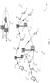
- FIG. 1 illustrates an example of a wireless communications system 100 in accordance with various aspects of the present disclosure.
- the wireless communications system 100 includes base stations 105, UEs 115, and a core network 130.
- the wireless communications system 100 may be a Long Term Evolution (LTE)/LTE-advanced (LTE-a) network.
- Wireless communications system 100 utilizes contention-based spectrum such as shared or unlicensed spectrum.
- UEs 115 and base stations 105 operate (e.g., receive and transmit) using multiple layers based on multiple antenna ports. When the number of layers exceeds a threshold, channel state information CSI RS is used instead of or in addition to CRS in order to determine channel state information.
- LTE Long Term Evolution
- LTE-a LTE-advanced
- Base stations 105 may wirelessly communicate with UEs 115 via one or more base station antennas. Each base station 105 may provide communication coverage for a respective geographic coverage area 110.
- Communication links 125 shown in wireless communications system 100 may include uplink (UL) transmissions from a UE 115 to a base station 105, or downlink (DL) transmissions, from a base station 105 to a UE 115.
- UEs 115 may be dispersed throughout the wireless communications system 100, and each UE 115 may be stationary or mobile.
- a UE 115 may also be referred to as a mobile station, a subscriber station, a remote unit, a wireless device, an access terminal, a handset, a user agent, a client, or some other suitable terminology.
- a UE 115 may also be a cellular phone, a wireless modem, a handheld device, a personal computer, a tablet, a personal electronic device, a machine type communication (MTC) device or the like.
- MTC machine type communication
- Base stations 105 may communicate with the core network 130 and with one another. For example, base stations 105 may interface with the core network 130 through backhaul links 132 (e.g., S1, etc.). Base stations 105 may communicate with one another over backhaul links 134 (e.g., X2, etc.) either directly or indirectly (e.g., through core network 130). Base stations 105 may perform radio configuration and scheduling for communication with UEs 115, or may operate under the control of a base station controller (not shown). In some examples, base stations 105 may be macro cells, small cells, hot spots, or the like. Base stations 105 may also be referred to as eNodeBs (eNBs) 105.
- eNodeBs eNodeBs
- a UE 115 may be configured to collaboratively communicate with multiple base stations 105 through, for example, Multiple Input Multiple Output (MIMO), Coordinated Multi-Point (CoMP), or other schemes.
- MIMO techniques use multiple antennas on the base stations or multiple antennas on the UE to take advantage of multipath environments to transmit multiple data streams.
- CoMP includes techniques for dynamic coordination of transmission and reception by a number of base stations 105 to improve overall transmission quality for UEs as well as increasing network and spectrum utilization.
- a base station 105 may insert periodic pilot symbols, such as CRS, in downlink transmissions to aid UEs 115 in channel estimation and coherent demodulation
- CRS may include one of multiple (e.g., 504) different cell identities. They may be modulated using quadrature phase shift keying (QPSK) and may be power boosted (e.g., transmitted at 6dB higher than the surrounding data elements) to make them resilient to noise and interference.
- QPSK quadrature phase shift keying
- CRS may be embedded in 4 to 16 resource elements in each resource block based on the number of antenna ports or layers (up to 4) of the receiving UEs 115.
- demodulation reference signals may be directed toward specific UEs 115 and may be transmitted on resource blocks assigned to those UEs115.
- DMRS may include signals on 6 resource elements in each resource block in which they are transmitted.
- the DMRS for different antenna ports may each utilize the same 6 resource elements, and may be distinguished using different orthogonal cover codes (e.g., masking each signal with a different combination of 1 or -1 in different resource elements). In some cases, two sets of DMRS may be transmitted in adjoining resource elements.
- CSI RS additional reference signals known as CSI RS may be included to aid in generating CSI, for example, in cases involving more than a threshold number of information layers in a signal.
- a UE 115 may transmit a combination of periodic sounding reference signal (SRS) and UL DMRS for link adaptation and demodulation, respectively.
- SRS periodic sounding reference signal
- UL DMRS UL DMRS
- a base station 105 may gather channel condition information from a UE 115 in order to efficiently configure and schedule the channel (e.g., communication link 125). This information may be sent from the UE 115 in the form of a channel state report or CSI.
- a channel state report may contain a rank indicator (RI) requesting a number of layers to be used for DL transmissions (e.g., based on the antenna ports of the UE 115), a precoding matrix indicator (PMI) indicating a preference for which precoder matrix should be used (based on the number of layers), and a channel quality indication (CQI) representing the highest modulation and coding scheme (MCS) that may be used.
- RI rank indicator
- PMI precoding matrix indicator
- CQI channel quality indication representing the highest modulation and coding scheme
- CQI may be calculated by a UE 115 after receiving predetermined pilot symbols described above, such as CRS or CSI RS. RI and PMI may be excluded if the UE 115 does not support spatial multiplexing (or is not in support spatial mode).
- the types of information included in the report may determine a reporting type.
- Channel state reports may be periodic or aperiodic. That is, a base station 105 may configure a UE 115 to send periodic reports at regular intervals, and may also request additional reports to be utilized.
- Aperiodic reports may include wideband reports indicating the channel quality across an entire cell bandwidth, UE selected reports indicating a subset of the preferred subbands, or configured reports in which the subbands reported are selected by the base station 105.
- wireless communications system 100 may utilize aperiodic CSI RS in contention-based spectrum.
- a UE 115 or base station 105 may operate (e.g., communicate) in a shared or unlicensed frequency spectrum, which is referred to herein as contention-based spectrum because various devices may be contending for access to the spectrum resources. These devices may perform a clear channel assessment (CCA) prior to communicating in order to determine whether the channel is available.
- CCA may include an energy detection procedure to determine whether there are any other active transmissions. For example, the device may infer that a change in a received signal strength indication (RSSI) of a power meter indicates that a channel is occupied. Specifically, signal power is that is concentrated in a certain bandwidth and exceeds a predetermined noise floor may indicate another wireless transmitter.
- RSSI received signal strength indication
- a CCA may also include detection of specific sequences that indicate use of the channel.
- another device may transmit a specific preamble prior to transmitting a data sequence.
- transmissions may be exempt from performing a CCA.
- Such a transmission may be known as a CCA exempt transmission (CET), and may be more specifically referred to as a D-CET or uplink CET (U-CET).
- CCA exempt transmission CET
- D-CET downlink CET
- U-CET uplink CET
- wireless communications system 100 may utilize one or more enhanced component carriers (eCCs).
- eCC may be characterized by one or more features including: flexible bandwidth, different transmission time interval (TTIs), and modified control channel configuration.
- TTIs transmission time interval
- an eCC may be associated with a carrier aggregation (CA) configuration or a dual connectivity configuration (e.g., when multiple serving cells have a suboptimal backhaul link).
- CA carrier aggregation
- An eCC may also be configured for use in contention-based spectrum, including unlicensed or shared spectrum (e.g., where more than one operator is licensed to use the spectrum).
- An eCC characterized by flexible bandwidth may include one or more segments that may be utilized by certain UEs 115 (e.g., MTCs) that may not be capable of monitoring the whole bandwidth or prefer to use a limited bandwidth (e.g., to conserve power).
- certain UEs 115 e.g., MTCs
- MTCs Mobility Management Entity
- a frame structure may be used to organize physical resources for communication via communication links 125.
- a frame may be a 10ms interval that may be further divided into 10 equally sized subframes.
- Each subframe may include two consecutive time slots.
- Each slot may include 6 or 7 orthogonal frequency division multiple access (OFDMA) symbol periods.
- a resource element consists of one symbol period and one subcarrier (a 15 KHz frequency range).
- a resource block may contain 12 consecutive subcarriers in the frequency domain and, for a normal cyclic prefix in each OFDM symbol, 7 consecutive OFDM symbols in the time domain (1 slot), or 84 resource elements.
- Some REs may include DL reference signals (DL-RS).
- the DL-RS may include a CRS, UE-RS, or CSI RS, or a combination of the three.
- the number of bits carried by each resource element may depend on the modulation scheme (the configuration of symbols that may be selected during each symbol period). Thus, the more resource blocks that a UE 115 receives and the
- an eCC may utilize a different TTI length than other component carriers (CCs), which may include use of a reduced or variable symbol duration as compared with TTIs of the other CCs.
- the symbol duration may remain the same, in some cases, but each symbol may represent a distinct TTI.
- an eCC may include multiple hierarchical layers associated with the different TTI lengths. For example, TTIs at one hierarchical layer may correspond to uniform 1ms subframes, whereas in a second layer, variable length TTIs may correspond to bursts of short duration symbol periods. In some cases, a shorter symbol duration may also be associated with increased subcarrier spacing.
- TDD time division duplex
- an eCC may utilize dynamic time division duplex (TDD) operation (i.e., it may switch from DL to UL operation for short bursts according to dynamic conditions.)
- TDD time division duplex
- Flexible bandwidth and variable TTIs may be associated with a modified control channel configuration (e.g., an eCC may utilize an enhanced physical downlink control channel (ePDCCH) for DL control information).
- ePDCCH enhanced physical downlink control channel
- one or more control channels of an eCC may utilize frequency-division multiplexing (FDM) scheduling to accommodate flexible bandwidth use.
- FDM frequency-division multiplexing
- Other control channel modifications include the use of additional control channels (e.g., for evolved multimedia broadcast multicast service (eMBMS) scheduling, or to indicate the length of variable length UL and DL bursts), or control channels transmitted at different intervals.
- An eCC may also include modified or additional hybrid automatic repeat request (HARQ) related control information.
- HARQ hybrid automatic repeat request
- UE 115 may, in some cases, receive signaling to indicate the presence of CSI RS (e.g., an aperiodic CSI RS), and may receive the CSI RS according to the signaling. The UE 115 may then compute a CQI based on CSI RS or CRS, or both, and may transmit the CQI in a report to a base station 105. In some cases, the CSI RS may be received following the PDCCH (e.g., in a symbol period immediately following PDCCH).
- CSI RS e.g., an aperiodic CSI RS
- a quasi-periodic CSI RS scheme may be employed, and the UE 115 may identify a periodic anchor subframe, and may locate a subframe with CSI RS based on an offset from the anchor subframe.
- Signaling indicating the presence of CSI RS may be broadcast (e.g., via a common physical downlink control channel (C-PDCCH), PCFICH, PFFICH, or the like) or unicast (e.g., via a PDCCH) to UEs 115.
- the signaling may include an indication of both the subframe type and the subframe length.
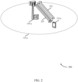
- FIG. 2 illustrates an example of a wireless communications system 200 for CSI RS in contention-based spectrum in accordance with various aspects of the present disclosure.
- Wireless communications system 200 may include a UE 115-a and base station 105-a, which may be examples of a UE 115 and base station 105 described with reference to FIG. 1 .
- Wireless communications system 200 may utilize periodic, aperiodic, quasi-periodic, or D-CET based CSI RS to support CQI reporting.
- Downlink channel 220 and uplink channel 225 may be used to communicate data and control information between base station 105-a and UE 115-a.
- Downlink channel 220 and uplink channel 225 may represent various data or control channels. For instance, the channels may be divided into or represented as logical channels, transport channels, and physical layer channels. Downlink channel 220 may also be classified into control channels and traffic channels.
- Logical control channels may include paging control channel (PCCH) for paging information, broadcast control channel (BCCH) for broadcast system control information, multicast control channel (MCCH) for transmitting multimedia broadcast multicast service (MBMS) scheduling and control information, dedicated control channel (DCCH) for transmitting dedicated control information, common control channel (CCCH) for random access information, dedicated traffic channel (DTCH) for dedicated UE data, and multicast traffic channel (MTCH) for multicast data.
- PCCH paging control channel
- BCCH broadcast control channel
- MCCH multicast control channel
- DCCH dedicated control channel
- CCCH common control channel
- DTCH dedicated traffic channel
- MTCH multicast traffic channel
- DL transport channels may include broadcast channel (BCH) for broadcast information, a downlink shared channel (DL-SCH) for data transfer, paging channel (PCH) for paging information, and multicast channel (MCH) for multicast transmissions.
- UL transport channels may include random access channel (RACH) for access and uplink shared channel (UL-SCH) for data.
- DL physical channels may include physical broadcast channel (PBCH) for broadcast information, PCFICH for control format information, PFFICH for frame format information (e.g., in contention-based spectrum), physical downlink control channel (PDCCH) for control and scheduling information, physical HARQ indicator channel (PHICH) for HARQ status messages, physical downlink shared channel (PDSCH) for user data and physical multicast channel (PMCH) for multicast data, C-PDCCH for frame format or timing information, including information related to various transmission opportunities (TxOP).
- UL physical channels may include physical random access channel (PRACH) for access messages, physical uplink control channel (PUCCH) for control data, and physical uplink shared channel (PUSCH) for user data.
- PRACH physical random access channel
- PUCCH physical uplink control channel
- PUSCH physical uplink shared channel
- a downlink channel 220 from the base station 105-a to the UE 115-a may utilize multiple transmission layers, for example, and may include downlink physical channels (e.g., PDCCH, C-PDCCH, PFFICH, PCFICH), which may indicate the existence of symbols that include CSI RS symbols or CRS symbols.
- Uplink channel 225 may also be used to transmit data and control using the various uplink channels described above.
- UE 115-a may calculate and transmit a CQI (e.g., based on the CRS, CSI RS, or both).
- the reference signal configuration may include aperiodic CSI RS, periodic CSI RS, quasi-periodic CSI RS, or D-CET based CSI RS.
- certain preambles may be transmitted, which may include or serve as a CRS for a certain number of antenna ports (e.g., up to four of which CRS ports). In some cases, however, and as discussed above, a greater number of antenna ports may be used (e.g., eight antenna port operations). Such operation may, for instance, be employed to target low-Doppler, flat-fading-channel UEs 115 (e.g., UE 115-a).
- This higher rank (e.g., increased layer) operation in a contention-based spectrum may be accomplished as described herein using CSI RS (e.g., integrated in a frame structure) for CQI measurements with reasonably low overhead, without puncturing data REs, and with support for CoMP operation.
- CSI RS e.g., integrated in a frame structure
- CSI RS may be included in OFDM symbols following a PDCCH portion of a transmission.
- the presence of such symbols may be indicated with a physical channel (or a portion of a physical channel), such as PCFICH or PFFICH.
- Aperiodic CSI RS may be employed with CRS, which may allow UE 115-a to use both CSI RS and CRS to compute CQI.
- UE 115-a may use CRS to compute CQI.
- aperiodic CSI RS may be employed for dedicated, on-demand CSI RS.
- UE 115-a may be triggered to report CQI after a DL burst with CSI RS, while other UEs may rely on CRS.
- base station 105-a may transmit more than one CSI RS in a DL burst. That is, base station 105-a may transmit a DL burst that includes different CSI RS directed to one or more UEs 115. For example, base station 105-a may transmit a DL burst including a first CSI RS directed to a UE 115 and a second CSI RS directed to a different UE 115. The UEs 115 may thus compute distinct CQI according to their respective CSI RS contained in the DL burst.
- PCFICH is configured with (e.g., conveyed) using two bits, which may be used to indicate one, two, or three OFDM symbols for PDCCH.
- the aperiodic CSI RS scheme may make use of the typically reserved field of '11' of PCFICH to indicate CSI RS presence in a TTI, for instance.
- PCFICH having a value' 11' can mean two PDCCH symbols followed by two CSI RS symbols. In some cases, this interpretation may apply to the last TTI rather than to each TTI.
- Such an aperiodic CSI RS may allow flexibility for resource allocation; for instance, if there are no UEs 115 within geographic coverage area 110-a configured to use CSI RS, base station 105-a (or the network operator) may simply opt not to include CSI RS in downlink transmissions.
- the presence of CSI RS may be indicated using PFFICH.
- the reserved fields of PCFICH may be unavailable, and using PFFICH may provide another readily available option.
- PFFICH may be configured with one or more entries (e.g., fields) to indicate multiple special frame formats with known CSI RS locations.
- PFFICH may, in some examples, be configured with additional bits that may be used to indicate CSI RS presence in each frame format.
- An aperiodic CSI RS scheme may be configured for CoMP operation (e.g., simultaneous transmission from multiple base stations 105).
- some systems including certain LTE/LTE-A systems (e.g., those employ release 10 of the LTE standard) may configure UEs 115 with multiple CSI RS processes to support CoMP operation.
- UEs 115 may be configured to monitor one or more CSI RS/CSI interference measurement (IMR) pair, where each pair may represent a serving/interfering assumption, and the UE may compute one CQI for each pair.
- IMR CSI interference measurement
- An aperiodic CSI RS scheme may, however, allow for coordinated transmission of CSI RS across base station 105 using CoMP.
- the base station 105 (including base station 105-a) using CoMP may thus select an ON/OFF pattern to transmit CSI RS in a process transparent to UEs 115; and the need to configure UE 115-a with multiple CSI RS processes may be avoided.
- base station 105-a in combination with other base stations 105 (not shown in FIG. 2 ; may include one or more base station 105 of FIG. 1 ) may identify UE 115-a as a UE to serve, and base station 105 may design a CoMP CSI RS pattern, and may collect UE 115-a CQI under that CSI RS pattern to make the scheduling decision.
- Potential losses in scheduling ability experienced by the base station 105-a that stem from choosing between multiple CoMP scenarios from multiple CQI feedbacks to make a scheduling decision may be mitigated by sending multiple CSI RS, collecting all CQIs, and then making a scheduling decision.
- a periodic CSI RS scheme may be employed.
- a fixed CSI RS location may be defined by a period and an offset within certain subframes.
- the location of the CSI RS may be signaled to UE 115-a by base station 105-a; but a periodic CSI RS scheme does not typically require instantaneous signaling to indicate CSI RS presence, like an aperiodic scheme, and thus may offer some reduction in system overhead in some cases.
- a period CSI RS scheme may also support multiple CSI RS process configurations within wireless communications system 200.
- the downlink channel 220 may be utilized by other devices or transmissions from other devices at time when base station 105-a intends to transmit CSI RS. That is, due to other uses of the downlink channel 220, base station 105-a may be unable to transmit CSI RS subframes according to the period. In such cases, UE 115-a may recognize that downlink channel 220 is not clear, and thus that a CSI RS subframe may not be present if, for example, UE 115-a does not detect a preamble from base station 105-a.
- base station 105-a may transmit a CSI RS subframe according to the predefined period irrespective of contending channel uses, despite potential scheduling restrictions.
- UE 115-a may thus monitor for CSI RS according to the period even if the UE 115-a is otherwise not monitoring the downlink channel 220; and UE 115-a may employ certain rate-matching techniques to properly receive CSI RS in such cases.
- CSI RS transmission time e.g., CSI RS period
- CSI RS may be defined according to a system time, rather than a frame time. That is, CSI RS may be transmitted in different subframe numbers of subsequent frames.
- a subframe with CSI RS may occur at various times within a frame, which may have implications on the processing timeline of UE 115-a. For instance, if a CSI RS subframe occurs at or near the end of a frame, UE 115-a may adjust its CQI computation accordingly.
- a quasi-periodic CSI RS design may alleviate some issues associated with periodic CSI RS.
- a CSI RS transmission may be associated with a particular subframe, which may be referred to as an anchor subframe.
- CSI RS transmissions may occur in a different subframe than the anchor subframe; for example, the subframe with CSI RS may be at a fixed relative location in the frame, where the fixed relative location can be known to UE 115-a.
- This scheme may avoid scenarios in which a CSI RS subframe is transmitted at or near the end of a frame and may thus allow, in some cases, additional processing time for UE 115-a to compute CSI RS based CQI. Further details of the quasi-periodic scheme are described below with reference to FIG. 5 .
- CSI RS may be D-CET based.
- D-CET may be a periodic DL transmission, to which CSI RS can be added.
- Such CSI RS schemes offer a degree of certainty of CSI RS transmission, and may require lower system overhead; but in some cases the frequency of CSI RS transmission may be relatively low because D-CET transmissions may be infrequent.
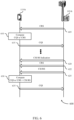
- FIG. 3 illustrates an example of a TTI set 300 for CSI RS in contention-based spectrum in accordance with various aspects of the present disclosure.
- TTI set 300 may include various frame or TTI configurations utilized by a UE 115 and base station 105, which may be examples of a UE 115 and base station 105 described with reference to FIGs. 1 and 2 .
- TTI set 300 includes example TTI structures 305 and 310. Both TTI structure 305 and 310 may be examples of transmissions on contention-based (e.g., unlicensed) spectrum.
- TTI structures 305 or 310, or both, may illustrate eCC transmissions.
- TTI structure 305 may illustrate a portion of a radio frame that includes subframes composed of LTE OFDM symbols.
- TTI structure 305 may, for instance, include a number of TTIs 315, which may be subframes composed of OFDM symbols 320 (e.g., 12 symbols per subframe for extended CP use).
- TTI 315-a may include two OFDM symbols carrying PDCCH 325 and ten additional OFDM symbols 320, which may be carry PDSCH, for instance.
- TTI 315-b may likewise include PDCCH 325 in two symbols, and may include as well as two symbols with CSI RS 330.
- TTI 315-b may be referred to, in some cases, as a CSI RS subframe.
- CSI RS 330 in TTI 315-b may represent periodic, aperiodic, quasi-periodic, or the like, transmissions, as described herein.
- the presence of CSI RS 330 may be indicated by signaling (including physical channel signaling) elsewhere in TTI structure 305.
- certain resource elements within symbols carrying PDCCH 325 may include PCFICH or C-PDCCH, which may indicate CSI RS 330 presence within TTI 315-b.
- TTI structure 310 may illustrate a portion of a dynamic TTI, for instance.
- TTI structure 310 may, for example, illustrate a short TTI used to convey control information or to indicate that a base station 105 is using a contention-based channel.
- TTI structure 310 may include two symbols carrying preamble 324, two symbols carrying PDCCH 325, and two symbols carrying CSI RS 330.
- CSI RS 330 in TTI structure 310 may represent periodic, aperiodic, quasi-periodic, or the like, transmissions, as described herein.
- CSI RS 330 in TTI structure 310 are indicated by PFFICH, which may be included in certain REs within symbols carrying PDCCH 325.
- TTI structure 310 may illustrate a periodic transmission, and CSI RS 330 may be included in each instance that TTI structure 310 is transmitted.
- CSI RS 330 may be transmitted during the final TTI of a DL burst (e.g., TTI 315-b) or during a short TTI (e.g., TTI structure 310).
- a CSI RS capable UE 115 may be triggered to report CQI, at which point the UE 115 may determine whether CSI RS 330 is present in the burst and use it accordingly.
- TTI structures 305 and 310 may illustrate a DL burst that includes multiple subsequent TTIs 315.
- a base station 105 may know a priori whether a UE 115 is reporting CQI based on CSI RS 330 by virtue of including CSI RS 330 in the DL burst. Because the last TTI of a burst may be the most recently updated, including CSI RS 330 in the last TTI may improve the accuracy of information from the CSI RS. In the case of a short TTI, the CSI RS 330 transmission may replace the PDSCH segments as a receiver processing timeline buffer.
- CSI RS 330 may be transmitted in any number of locations within a TTI (e.g., subframe) or TTI structure (e.g., frame). For instance, the CSI RS may be transmitted during the earlier TTIs of a DL burst (e.g., TTI 315-a). This may allow for more time for CQI computation by a UE 115.
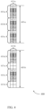
- FIG. 4 illustrates an example of CSI RS resource block (RB) formats 400 for CSI RS in contention-based spectrum in accordance with various aspects of the present disclosure.
- CSI RS RB formats 400 may utilized by a UE 115 and base station 105 for CSI RS based measurements, as described with reference to FIGs. 1 and 2 .
- RB 405-a may have a 900KHz bandwidth and may represent two symbols, which may be examples of CSI RS 330 of FIG. 3 , containing 12 tone pairs 415-a.
- RB 405-b may likewise have a 900KHz bandwidth and may represent two symbols, which may be examples of symbols with CSI RS 330 of FIG. 3 , containing 12 tone pairs 415-b.
- RB 405-a may include three samples of CSI RS 410-a, 410-b, and 410-c for eight antenna ports, or one sample per 300KHz.
- RB 405-b may be configured with two samples of CSI RS 410-d and 410-e, or one sample per 450KHz, which may provide additional REs available for IMR (e.g., interference measurement gaps) 415-a and 415-b.
- IMR interference measurement gaps
- CSI RS density may be determined to accommodate IMR, and may therefore be based on interference measurement gaps.
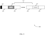
- FIG. 5 illustrates an example of a frame 500 (e.g., a radio frame) containing CSI RS in contention-based spectrum in accordance with various aspects of the present disclosure.
- Frame 500 may include a preamble 502, CSI RS subframe 505, and an anchor subframe 510, as well as several other subframes 520.
- Frame 500 may be utilized by a UE 115 and base station 105, which may be examples of a UE 115 and base station 105 described with reference to FIGs. 1 and 2 .
- Frame 500 may also be an example of a TTI structure (e.g., TTI structure 305) of FIG. 3 .
- TTI structure e.g., TTI structure 305
- a quasi-periodic CSI RS scheme may be employed using frame 500, for instance.
- a system may be configured such that a base station 105 transmits CSI RS according to a period known to a UE 115.
- the period of CSI RS may align with an anchor subframe 510, which may or may not be present in a given frame.
- a UE 115 may determine whether an anchor subframe 510 is present in frame 500.
- UE 115 may then determine an exact location of the subframe of anchor subframe 510 (e.g., CSI RS subframe 505) based on the presence of anchor subframe 510 and an offset 515.
- the offset 515 represents a relative location of CSI RS subframe 505 within frame 500.
- CSI RS subframe 505 may be subframe number 2 of each frame 500 determined to include an anchor subframe 510.
- the location of CSI RS subframe 505 may be known or communicated to UE 115.
- signaling in preamble 502 may be used to determine that frame 500 includes anchor subframe 510.
- CSI RS periodicity and the offset 515 may be known a priori by a UE 115 or may be communicated in radio resource control (RRC) signaling, system information broadcasts, or the like.
- RRC radio resource control
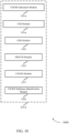
- FIG. 6 illustrates an example of a process flow 600 for CSI RS in contention-based spectrum in accordance with various aspects of the present disclosure.
- Process flow 600 may include a UE 115-b and base station 105-b, which may be examples of a UE 115 and base station 105 described with reference to FIGs. 1 and 2 .
- process flow 600 may represent a method or methods of communication using aperiodic CSI RS in contention-based spectrum.
- base station 105-b may transmit CRS to UE 115-b.
- receiving the CRS includes receiving a preamble including the CRS.
- UE 115-b may compute CQI based on the CRS. That is, the CQI may be computed without CSI RS (e.g., if the number of communication layers is below a threshold or if CSI RS is not present).
- UE 115-b may transmit a CQI report to base station 105-b.
- UE 115-b may transmit a CSI RS indication to UE 115-b. That is, prior to transmitting the CSI RS, base station 105 may transmit an indication of the presence of CSI RS to UE 115-b.
- the signaling indicative of the CSI RS presence includes a portion of a PCFICH. In some examples the signaling indicative of the CSI RS presence includes a portion of a PFFICH.
- UE 115-b may transmit CRS to UE 115-b.
- base station 105-b may transmit CSI RS to UE 115-b.
- UE 115-b may receive the CSI RS according to the received signaling indicative of CSI RS presence.
- UE 115-b may receive a PDCCH, such that the CSI RS may be received following the PDCCH.
- the signaling indicative of the CSI RS presence is a physical channel.
- the CSI RS includes a plurality of symbol periods. A density of the CSI RS may, for instance, be based on an interference measurement gap, as described above.
- receiving the CSI RS includes receiving the CSI RS in a final TTI of a DL burst. In some examples receiving the CSI RS includes: receiving a DL TTI burst including a first CSI RS and a second CSI RS according to the signaling, such that the CQI may include a first CQI computed based on the first CSI RS and a second CQI computed based on the second CSI RS.
- UE 115-b may compute CQI based on the CRS and CSI RS (e.g., if the number of communication layers is above a threshold).
- UE 115-b may transmit a CQI report to base station 105-b.
- FIG. 7 illustrates an example of a process flow 700 for CSI RS in contention-based spectrum in accordance with various aspects of the present disclosure.
- Process flow 700 may include a UE 115-c and base station 105-c, which may be examples of a UE 115 and base station 105 described with reference to FIGs. 1-2 .
- Process flow 700 may represent a method or methods of communication using quasi-periodic CSI RS in contention-based spectrum, for example.
- UE 115-c may identify an anchor subframe. That is, UE 115-c may identify a first subframe indicative of a CSI RS presence, which may be referred to as an anchor subframe in some cases.
- UE 115-c may identify a CSI RS subframe based on an offset from the anchor subframe. UE 115-c may thus determine that a second subframe includes the CSI RS based on the identified first subframe and an offset. In some examples UE 115-c may also determine frame information. In some examples, determining frame information is based on a preamble or a PFFICH, or both, and identifying the first subframe may include determining that a frame includes the first subframe, which may be based on the frame information and a periodicity of the first subframe.
- the offset between the first and second subframes may be indicated with signaling between the base station 105-c and the UE 115-c as discussed above.
- the offset includes a relative location of the second subframe within a frame.
- UE 115-c may receive a CSI RS from base station 105-c during the CSI RS subframe. For example, UE 115-c may receive the CSI RS during the second subframe.
- base station 105-c may transmit signaling indicative of a CSI RS presence and may transmit the CSI RS according to the signaling.
- UE 115-c may compute CQI based on the CSI RS.
- UE 115-c may report the CQI to base station 105-c, and base station 105-c may receive a report including CQI computed based on the CSI RS.
- FIG. 8 shows a diagram of a wireless device 800 that supports CSI RS in contention-based spectrum in accordance with various aspects of the present disclosure.
- Wireless device 800 may be an example of aspects of a UE 115 described with reference to FIGs. 1-7 .
- Wireless device 800 may include a receiver 805, a CSI RS module 810, or a transmitter 815.
- Wireless device 800 may also include a processor. Each of these components may be in communication with one another.
- the receiver 805 may receive information such as packets, user data, or control information associated with various information channels (e.g., control channels, data channels, and information related to CSI RS in unlicensed spectrum, etc.). Information may be passed on to the CSI RS module 810, and to other components of wireless device 800. In some examples, the receiver 805 may receive the CSI RS according to the received signaling. In some examples, receiving the CSI RS includes receiving the CSI RS in a final TTI of a DL burst.
- receiving the CSI RS may include receiving a DL TTI burst that has a first CSI RS and a second CSI RS, such that CQI may include a first CQI computed based the first CSI RS, and a second CQI computed based on the second CSI RS.
- the receiver 805 may receive the CSI RS during the second subframe.
- the CSI RS module 810 may receive signaling indicative of a CSI RS presence, receive the CSI RS according to the received signaling, and compute a CQI based on CSI RS.
- the transmitter 815 may transmit signals received from other components of wireless device 800.
- the transmitter 815 may be collocated with the receiver 805 in a transceiver module.
- the transmitter 815 may include a single antenna, or it may include a plurality of antennas.
- the transmitter 815 may transmit a report including the CQI, such that the report may include an indication that the CQI is based on the CSI RS.
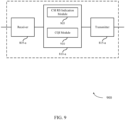
- FIG. 9 shows a diagram of a wireless device 900 that supports CSI RS in contention-based spectrum in accordance with various aspects of the present disclosure.
- Wireless device 900 may be an example of aspects of a wireless device 800 or a UE 115 described with reference to FIGs. 1-8 .
- Wireless device 900 may include a receiver 805-a, a CSI RS module 810-a, or a transmitter 815-a.
- Wireless device 900 may also include a processor. Each of these components may be in communication with one another.
- the CSI RS module 810-a may also include a CSI RS indication module 905, and a CQI module 910.
- the receiver 805-a may receive information which may be passed on to CSI RS module 810-a, and to other components of wireless device 900.
- the CSI RS module 810-a may perform the operations described with reference to FIG. 8 .
- the transmitter 815-a may transmit signals received from other components of wireless device 900.
- the CSI RS indication module 905 may receive signaling indicative of a CSI RS presence as described with reference to FIGs. 2-7 .
- the signaling indicative of the CSI RS presence includes a physical channel.
- the signaling indicative of the CSI RS presence includes a portion of a PCFICH or a portion of a PFFICH, in various examples.
- the CQI module 910 may compute a CQI based on CSI RS as described with reference to FIGs. 2-7 .
- the CQI module 910 may also determine that the CQI was computed using the CSI RS based on transmitting the CSI RS.
- the CQI module 910 may also determine that the CQI was computed using the CSI RS based on an indicator received from a UE, such that the report may include the indicator.
- FIG. 10 shows a diagram 1000 of a CSI RS module 810-b which may be a component of a wireless device 800 or a wireless device 900 that supports CSI RS in contention-based spectrum in accordance with various aspects of the present disclosure.
- the CSI RS module 810-b may be an example of aspects of a CSI RS module 810 described with reference to FIGs. 8-9 .
- the CSI RS module 810-b may include a CSI RS indication module 905-a, and a CQI module 910-a. Each of these modules may perform the functions described with reference to FIG. 9 .
- the CSI RS module 810-b may also include a CRS module 1005, a PDCCH module 1010, a CSI RS module 1015, and a CSI RS subframe identification module 1020.
- the CRS module 1005 may receive a CRS, and the CQI may be based on the CRS as described with reference to FIGs. 2-7 .
- receiving the CRS includes receiving a preamble including the CRS.
- the PDCCH module 1010 may receive a PDCCH, and the CSI RS may be received following the PDCCH as described with reference to FIGs. 2-7 .
- the CSI RS module 1015 may be configured such that the CSI RS may include a plurality of symbol periods as described with reference to FIGs. 2-7 .
- a density of the CSI RS may be based on an interference measurement gap.
- the CSI RS subframe identification module 1020 may identify a first subframe (e.g, an anchor subframe) indicative of a CSI RS presence as described with reference to FIGs. 2-7 .
- the CSI RS subframe identification module 1020 may also determine that a second subframe (e.g., CSI RS subframe) includes the CSI RS based on the identified first subframe and an offset.
- determining frame information is based on a preamble or a PFFICH, or both, such that identifying the first subframe may include determining that the frame includes the first subframe based on the frame information and a periodicity of the first subframe.
- the CSI RS subframe identification module 1020 may also receive signaling indicative of the offset.
- the offset may be a relative location of the second subframe in the frame.
- the CSI RS subframe identification module 1020 may also determine that a second subframe includes the CSI RS based on the identified first subframe and an offset.
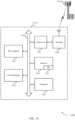
- FIG. 11 shows a diagram of a system 1100, including a UE 115, that supports CSI RS in contention-based spectrum in accordance with various aspects of the present disclosure.
- System 1100 may include UE 115-d, which may be an example of a wireless device 800, a wireless device 900, or a UE 115 described with reference to FIGs. 1 , 2 and 8-10 .
- UE 115-d may include a CSI RS module 1110, which may be an example of a CSI RS module 810 described with reference to FIGs. 8-10 .
- UE 115-d may also include an ECC module1125.
- the ECC module 1125 may enable UE 115-d to operate according to ECC procedures as described with reference to FIG. 1 .
- UE 115-d may also include components for bi-directional voice and data communications including components for transmitting communications and components for receiving communications. For example, UE 115-d may communicate bi-directionally with base station 105-d.
- UE 115-d may also include a processor 1105, and memory 1115 (including software (SW) 1120), a transceiver 1135, and one or more antenna(s) 1140, each of which may communicate, directly or indirectly, with one another (e.g., via buses 1145).
- the transceiver 1135 may communicate bi-directionally, via the antenna(s) 1140 or wired or wireless links, with one or more networks, as described above.
- the transceiver 1135 may communicate bi-directionally with a base station 105 or another UE 115.
- the transceiver 1135 may include a modem to modulate the packets and provide the modulated packets to the antenna(s) 1140 for transmission, and to demodulate packets received from the antenna(s) 1140. While UE 115-d may include a single antenna 1140, UE 115-d may also have multiple antennas 1140 capable of concurrently transmitting or receiving multiple wireless transmissions.
- the memory 1115 may include random access memory (RAM) and read only memory (ROM).
- the memory 1115 may store computer-readable, computer-executable software/firmware code 1120 including instructions that, when executed, cause the processor 1105 to perform various functions described herein (e.g., CSI RS in unlicensed spectrum, etc.).
- the software/firmware code 1120 may not be directly executable by the processor 1105 but cause a computer (e.g., when compiled and executed) to perform functions described herein.
- the processor 1105 may include an intelligent hardware device, (e.g., a central processing unit (CPU), a microcontroller, an application specific integrated circuit (ASIC), etc.)
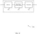
- FIG. 12 shows a diagram of a wireless device 1200 that supports CSI RS in contention-based spectrum in accordance with various aspects of the present disclosure.
- Wireless device 1200 may be an example of aspects of a base station 105 described with reference to FIGs. 1-11 .
- Wireless device 1200 may include a receiver 1205, a base station CSI RS module 1210, or a transmitter 1215.
- Wireless device 1200 may also include a processor. Each of these components may be in communication with one another.
- the receiver 1205 may receive information such as packets, user data, or control information associated with various information channels (e.g., control channels, data channels, and information related to CSI RS in unlicensed spectrum, etc.). Information may be passed on to the base station CSI RS module 1210, and to other components of wireless device 1200.
- information channels e.g., control channels, data channels, and information related to CSI RS in unlicensed spectrum, etc.
- Information may be passed on to the base station CSI RS module 1210, and to other components of wireless device 1200.
- the base station CSI RS module 1210 may transmit signaling indicative of a CSI RS presence, transmit the CSI RS according to the signaling, and receive a report including CQI computed based on the CSI RS.
- the transmitter 1215 may transmit signals received from other components of wireless device 1200.
- the transmitter 1215 may be collocated with the receiver 1205 in a transceiver module.
- the transmitter 1215 may include a single antenna, or it may include a plurality of antennas.
- the transmitter 1215 may transmit the CSI RS according to the signaling.
- the transmitter 1215 may transmit the CSI RS during the second subframe.
- FIG. 13 shows a diagram of a wireless device 1300 that supports CSI RS in contention-based spectrum in accordance with various aspects of the present disclosure.
- Wireless device 1300 may be an example of aspects of a wireless device 1200 or a base station 105 described with reference to FIGs. 1-12 .
- Wireless device 1300 may include a receiver 1205-a, a base station CSI RS module 1210-a, or a transmitter 1215-a.
- Wireless device 1300 may also include a processor. Each of these components may be in communication with one another.
- the base station CSI RS module 1210-a may also include a base station CSI RS indication module 1305, a base station CQI module 1310, and a base station CSI RS subframe identification module 1315.
- the receiver 1205-a may receive information which may be passed on to base station CSI RS module 1210-a, and to other components of wireless device 1300.
- the base station CSI RS module 1210-a may perform the operations described with reference to FIG. 12 .
- the transmitter 1215-a may transmit signals received from other components of wireless device 1300.
- the base station CSI RS indication module 1305 may transmit signaling indicative of a CSI RS presence as described with reference to FIGs. 2-7 .
- the base station CQI module 1310 may receive a report including CQI computed based on the CSI RS as described with reference to FIGs. 2-7 .
- the base station CSI RS subframe identification module 1315 may identify a first subframe indicative of a channel CSI RS presence as described with reference to FIGs. 2-7 .
- FIG. 14 shows a diagram 1400 of a base station CSI RS module 1210-b which may be a component of a wireless device 1200 or a wireless device 1300 that supports CSI RS in contention-based spectrum in accordance with various aspects of the present disclosure.
- the base station CSI RS module 1210-b may be an example of aspects of a base station CSI RS module 1210 described with reference to FIGs. 12-13 .
- the base station CSI RS module 1210-b may include a base station CSI RS indication module 1305-a, a base station CQI module 1310-a, and a base station CSI RS subframe identification module 1315-a. Each of these modules may perform the functions described with reference to FIG. 13 .
- the base station CSI RS module 1210-b may also include a UE identification module 1405, a transmission pattern module 1410, a COMP transmission module 1415, and an offset indication module 1420.
- the UE identification module 1405 may identify a UE configured for CSI RS based CQI reporting; and the signaling may be transmitted based on identifying the UE as described with reference to FIGs. 2-7 .
- the transmission pattern module 1410 may determine a transmission pattern for serving a UE in a CoMP scheme as described with reference to FIGs. 2-7 .
- the COMP transmission module 1415 may transmit the CSI RS and the signaling based on the transmission pattern as described with reference to FIGs. 2-7 .
- the offset indication module 1420 may transmit signaling indicative of the offset as described with reference to FIGs. 2-7 .
- the offset includes a relative location of, e.g., a CSI RS subframe in a frame.
- FIG. 15 shows a diagram of a system 1500, including a base station 105, that supports CSI RS in contention-based spectrum in accordance with various aspects of the present disclosure.
- System 1500 may include base station 105-e, which may be an example of a wireless device 1200, a wireless device 1300, or a base station 105 described with reference to FIGs. 1 , 2 , and 12-14 .
- Base station 105-e may include a base station CSI RS module 1510, which may be an example of a base station CSI RS module 1210 described with reference to FIGs. 12-14 .
- Base station 105-e may also include components for bi-directional voice and data communications including components for transmitting communications and components for receiving communications. For example, base station 105-e may communicate bi-directionally with UE 115-e or UE 115-f.
- base station 105-e may have one or more wired backhaul links.
- Base station 105-e may have a wired backhaul link (e.g., S1 interface, etc.) to the core network 130.
- Base station 105-e may also communicate with other base stations 105, such as base station 105-f and base station 105-g via inter-base station backhaul links (e.g., an X2 interface).
- Each of the base stations 105 may communicate with UEs 115 using the same or different wireless communications technologies.
- base station 105-e may communicate with other base stations such as 105-f or 105-g utilizing base station communications module 1525.
- base station communications module 1525 may provide an X2 interface within a Long Term Evolution (LTE)/LTE-A wireless communication network technology to provide communication between some of the base stations 105.
- base station 105-e may communicate with other base stations through core network 130.
- base station 105-e may communicate with the core network 130 through network communications module 1530.
- LTE Long Term Evolution
- the base station 105-e may include a processor 1505, memory 1515 (including software (SW) 1520), transceiver 1535, and antenna(s) 1540, which each may be in communication, directly or indirectly, with one another (e.g., over bus system 1545).
- the transceivers 1535 may be configured to communicate bi-directionally, via the antenna(s) 1540, with the UEs 115, which may be multi-mode devices.
- the transceiver 1535 (or other components of the base station 105-e) may also be configured to communicate bi-directionally, via the antennas 1540, with one or more other base stations (not shown).
- the transceiver 1535 may include a modem configured to modulate the packets and provide the modulated packets to the antennas 1540 for transmission, and to demodulate packets received from the antennas 1540.
- the base station 105-e may include multiple transceivers 1535, each with one or more associated antennas 1540.
- the transceiver may be an example of a combined receiver 1205 and transmitter 1215 of FIG. 12 .
- the memory 1515 may include RAM and ROM.
- the memory 1515 may also store computer-readable, computer-executable software code 1520 containing instructions that are configured to, when executed, cause the processor 1505 to perform various functions described herein (e.g., CSI RS in unlicensed spectrum, selecting coverage enhancement techniques, call processing, database management, message routing, etc.).
- the software 1520 may not be directly executable by the processor 1505 but be configured to cause the computer (e.g., when compiled and executed) to perform functions described herein.
- the processor 1505 may include an intelligent hardware device (e.g., a CPU, a microcontroller, an ASIC, etc.).
- the processor 1505 may include various special purpose processors such as encoders, queue processing modules, base band processors, radio head controllers, digital signal processor (DSPs), and the like.
- the base station communications module 1525 may manage communications with other base stations 105.
- a communications management module may include a controller or scheduler for controlling communications with UEs 115 in cooperation with other base stations 105.
- the base station communications module 1525 may coordinate scheduling for transmissions to UEs 115 for various interference mitigation techniques such as beamforming or joint transmission.
- wireless device 800, wireless device 900, and CSI RS module 810 wireless device 1200, wireless device 1300, base station CSI RS module 1210, and system 1500 may, individually or collectively, be implemented with at least one ASIC adapted to perform some or all of the applicable functions in hardware.
- the functions may be performed by one or more other processing units (or cores), on at least one IC.
- other types of integrated circuits may be used (e.g., Structured/Platform ASICs, a field programmable gate array (FPGA), or another semi-custom IC), which may be programmed in any manner known in the art.
- the functions of each unit may also be implemented, in whole or in part, with instructions embodied in a memory, formatted to be executed by one or more general or application-specific processors.
- FIG. 16 shows a flowchart illustrating a method 1600 for CSI RS in contention-based spectrum in accordance with various aspects of the present disclosure.
- the operations of method 1600 may be implemented by a UE 115 or its components as described with reference to FIGs. 1-15 .
- the operations of method 1600 may be performed by the CSI RS module 810 as described with reference to FIGs. 8-11 .
- a UE 115 may execute a set of codes to control the functional elements of the UE 115 to perform the functions described below. Additionally or alternatively, the UE 115 may perform aspects the functions described below using special-purpose hardware.
- the UE 115 may receive signaling indicative of a CSI RS presence as described with reference to FIGs. 2-7 .
- the operations of block 1605 may be performed by the CSI RS indication module 905 as described with reference to FIG. 9 .
- the UE 115 may receive the CSI RS according to the received signaling as described with reference to FIGs. 2-7 .
- the operations of block 1610 may be performed by the receiver 805 as described with reference to FIG. 8 .
- the UE 115 may compute a CQI based at least in part on CSI RS as described with reference to FIGs. 2-7 .
- the operations of block 1615 may be performed by the CQI module 910 as described with reference to FIG. 9 .
- the UE 115 may receive signaling indicative of a CSI RS presence as described with reference to FIGs. 2-7 .
- the operations of block 1705 may be performed by the CSI RS indication module 905 as described with reference to FIG. 9 .
- the UE 115 may receive a CRS, such that the CQI may be based at least in part on the CRS as described with reference to FIGs. 2-7 .
- the operations of block 1710 may be performed by the CRS module 1005 as described with reference to FIG. 10 .
- the UE 115 may receive the CSI RS according to the received signaling as described with reference to FIGs. 2-7 .
- the operations of block 1715 may be performed by the receiver 805 as described with reference to FIG. 8 .
- the UE 115 may compute a CQI based at least in part on CSI RS as described with reference to FIGs. 2-7 .
- the operations of block 1720 may be performed by the CQI module 910 as described with reference to FIG. 9 .
- the UE 115 may compute a CQI based at least in part on CSI RS as described with reference to FIGs. 2-7 .
- the operations of block 1820 may be performed by the CQI module 910 as described with reference to FIG. 9 .
- the UE 115 may receive signaling indicative of a CSI RS presence as described with reference to FIGs. 2-7 .
- the operations of block 1905 may be performed by the CSI RS indication module 905 as described with reference to FIG. 9 .
- the UE 115 may receive the CSI RS according to the received signaling as described with reference to FIGs. 2-7 .
- the operations of block 1910 may be performed by the receiver 805 as described with reference to FIG. 8 .
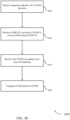
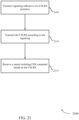
- FIG. 20 shows a flowchart illustrating a method 2000 for CSI RS in contention-based spectrum in accordance with various aspects of the present disclosure.
- the operations of method 2000 may be implemented by a UE 115 or its components as described with reference to FIGs. 1-15 .
- the operations of method 2000 may be performed by the CSI RS module 810 as described with reference to FIGs. 8-11 .
- a UE 115 may execute a set of codes to control the functional elements of the UE 115 to perform the functions described below. Additionally or alternatively, the UE 115 may perform aspects the functions described below using special-purpose hardware.
- the method 2000 may also incorporate aspects of methods 1600, 1700, 1800, and 1900 of FIGs. 16-19 .
- the UE 115 may determine that a second subframe includes the CSI RS based at least in part on the identified first subframe and an offset as described with reference to FIGs. 2-7 .
- the operations of block 2010 may be performed by the CSI RS subframe identification module 1020 as described with reference to FIG. 10 .
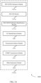
- FIG. 21 shows a flowchart illustrating a method 2100 for CSI RS in contention-based spectrum in accordance with various aspects of the present disclosure.
- the operations of method 2100 may be implemented by a base station 105 or its components as described with reference to FIGs. 1-15 .
- the operations of method 2100 may be performed by the base station CSI RS module 1210 as described with reference to FIGs. 12-15 .
- a base station 105 may execute a set of codes to control the functional elements of the base station 105 to perform the functions described below. Additionally or alternatively, the base station 105 may perform aspects the functions described below using special-purpose hardware.
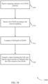
- the base station 105 may transmit signaling indicative of a CSI RS presence as described with reference to FIGs. 2-7 .
- the operations of block 2105 may be performed by the base station CSI RS indication module 1305 as described with reference to FIG. 13 .
- the base station 105 may transmit the CSI RS according to the signaling as described with reference to FIGs. 2-7 .
- the operations of block 2110 may be performed by the transmitter 1215 as described with reference to FIG. 12 .
- the base station 105 may receive a report including CQI computed based at least in part on the CSI RS as described with reference to FIGs. 2-7 .
- the operations of block 2115 may be performed by the base station CQI module 1310 as described with reference to FIG. 13 .
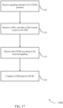
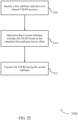
- the base station 105 may identify a first subframe indicative of a channel CSI RS presence as described with reference to FIGs. 2-7 .
- the operations of block 2205 may be performed by the base station CSI RS subframe identification module 1315 as described with reference to FIG. 13 .
- the base station 105 may determine that a second subframe includes the CSI RS based at least in part on the identified first subframe and an offset as described with reference to FIGs. 2-7 .
- the operations of block 2210 may be performed by the CSI RS subframe identification module 1020 as described with reference to FIG. 10 .
- the base station 105 may transmit the CSI RS during the second subframe as described with reference to FIGs. 2-7 .
- the operations of block 2215 may be performed by the transmitter 1215 as described with reference to FIG. 12 .
- methods 1600, 1700, 1800, 1900, 2000, 2100, and 2200 may provide for CSI RS in unlicensed spectrum. It should be noted that methods 1600, 1700, 1800, 1900, 2000, 2100, and 2200 describe possible implementation, and that the operations and the steps may be rearranged or otherwise modified such that other implementations are possible. In some examples, aspects from two or more of the methods 1600, 1700, 1800, 1900, 2000, 2100, and 2200 may be combined.
- CDMA code division multiple access
- TDMA time division multiple access
- FDMA frequency division multiple access
- OFDMA orthogonal frequency division multiple access
- SC-FDMA single carrier frequency division multiple access
- CDMA2000 covers IS-2000, IS-95, and IS-856 standards.
- IS-2000 Releases 0 and A are commonly referred to as CDMA2000 1X, 1X, etc.
- IS-856 (TIA-856) is commonly referred to as CDMA2000 1 ⁇ EV-DO, High Rate Packet Data (HRPD), etc.
- UTRA includes Wideband CDMA (WCDMA) and other variants of CDMA.
- WCDMA Wideband CDMA
- a time division multiple access (TDMA) system may implement a radio technology such as Global System for Mobile Communications (GSM).
- GSM Global System for Mobile Communications
- An orthogonal frequency division multiple access (OFDMA) system may implement a radio technology such as Ultra Mobile Broadband (UMB), Evolved UTRA (E-UTRA), IEEE 802.11 (Wi-Fi), IEEE 802.16 (WiMAX), IEEE 802.20, Flash-OFDM, etc.
- UMB Ultra Mobile Broadband
- E-UTRA Evolved UTRA
- Wi-Fi Wi-Fi
- WiMAX IEEE 802.16
- IEEE 802.20 Flash-OFDM
- UMB Ultra Mobile Broadband
- E-UTRA Evolved UTRA
- LTE and LTE-advanced (LTE-a) are new releases of Universal Mobile Telecommunications System (UMTS) that use E-UTRA.
- UTRA, E-UTRA, Universal Mobile Telecommunications System (UMTS), LTE, LTE-a, and Global System for Mobile communications (GSM) are described in documents from an organization named "3rd Generation Partnership Project” (3GPP).
- CDMA2000 and UMB are described in documents from an organization named "3rd Generation Partnership Project 2" (3GPP2).
- the techniques described herein may be used for the systems and radio technologies mentioned above as well as other systems and radio technologies.
- the term evolved node B may be generally used to describe the base stations.
- the wireless communications system or systems described herein may include a heterogeneous LTE/LTE-a network in which different types of evolved node B (eNBs) provide coverage for various geographical regions.
- eNBs evolved node B
- each eNB or base station may provide communication coverage for a macro cell, a small cell, or other types of cell.
- cell is a 3GPP term that can be used to describe a base station, a carrier or component carrier associated with a base station, or a coverage area (e.g., sector, etc.) of a carrier or base station, depending on context.
- Base stations may include or may be referred to by those skilled in the art as a base transceiver station, a radio base station, an access point, a radio transceiver, a NodeB, eNodeB (eNB), Home NodeB, a Home eNodeB, or some other suitable terminology.
- the geographic coverage area for a base station may be divided into sectors making up a portion of the coverage area.
- the wireless communications system or systems described herein may include base stations of different types (e.g., macro or small cell base stations).
- the UEs described herein may be able to communicate with various types of base stations and network equipment including macro eNBs, small cell eNBs, relay base stations, and the like. There may be overlapping geographic coverage areas for different technologies.
- a macro cell generally covers a relatively large geographic area (e.g., several kilometers in radius) and may allow unrestricted access by UEs with service subscriptions with the network provider.
- a small cell is a lower-powered base station, as compared with a macro cell, that may operate in the same or different (e.g., licensed, unlicensed, etc.) frequency bands as macro cells.
- Small cells may include pico cells, femto cells, and micro cells according to various examples.
- a pico cell for example, may cover a small geographic area and may allow unrestricted access by UEs with service subscriptions with the network provider.
- a femto cell may also cover a small geographic area (e.g., a home) and may provide restricted access by UEs having an association with the femto cell (e.g., UEs in a closed subscriber group (CSG), UEs for users in the home, and the like).
- An eNB for a macro cell may be referred to as a macro eNB.
- An eNB for a small cell may be referred to as a small cell eNB, a pico eNB, a femto eNB, or a home eNB.
- An eNB may support one or multiple (e.g., two, three, four, and the like) cells (e.g., component carriers).
- a UE may be able to communicate with various types of base stations and network equipment including macro eNBs, small cell eNBs, relay base stations, and the like.
- the wireless communications system or systems described herein may support synchronous or asynchronous operation.
- the base stations may have similar frame timing, and transmissions from different base stations may be approximately aligned in time.
- the base stations may have different frame timing, and transmissions from different base stations may not be aligned in time.
- the techniques described herein may be used for either synchronous or asynchronous operations.
- Each communication link described herein-including, for example, wireless communications system 100 and 200 of FIGs. 1 and 2- may include one or more carriers, where each carrier may be a signal made up of multiple sub-carriers (e.g., waveform signals of different frequencies). Each modulated signal may be sent on a different sub-carrier and may carry control information (e.g., reference signals, control channels, etc.), overhead information, user data, etc.
- the communication links described herein e.g., communication links 125 of FIG.
- FDD frequency division duplex
- TDD time division duplex
- Frame structures may be defined for frequency division duplex (FDD) (e.g., frame structure type 1) and TDD (e.g., frame structure type 2).
- Information and signals described herein may be represented using any of a variety of different technologies and techniques.
- data, instructions, commands, information, signals, bits, symbols, and chips that may be referenced throughout the above description may be represented by voltages, currents, electromagnetic waves, magnetic fields or particles, optical fields or particles, or any combination thereof.
- a general-purpose processor may be a microprocessor, but in the alternative, the processor may be any conventional processor, controller, microcontroller, or state machine.
- a processor may also be implemented as a combination of computing devices (e.g., a combination of a digital signal processor (DSP) and a microprocessor, multiple microprocessors, one or more microprocessors in conjunction with a DSP core, or any other such configuration).
- DSP digital signal processor
- the functions described herein may be implemented in hardware, software executed by a processor, firmware, or any combination thereof. If implemented in software executed by a processor, the functions may be stored on or transmitted over as one or more instructions or code on a computer-readable medium. Other examples and implementations are within the scope of the disclosure and appended claims. For example, due to the nature of software, functions described above can be implemented using software executed by a processor, hardware, firmware, hardwiring, or combinations of any of these. Features implementing functions may also be physically located at various positions, including being distributed such that portions of functions are implemented at different physical locations.
- Computer-readable media includes both non-transitory computer storage media and communication media including any medium that facilitates transfer of a computer program from one place to another.
- a non-transitory storage medium may be any available medium that can be accessed by a general purpose or special purpose computer.
- non-transitory computer-readable media can include RAM, ROM, electrically erasable programmable read only memory (EEPROM), compact disk (CD) ROM or other optical disk storage, magnetic disk storage or other magnetic storage devices, or any other non-transitory medium that can be used to carry or store desired program code means in the form of instructions or data structures and that can be accessed by a general-purpose or special-purpose computer, or a general-purpose or special-purpose processor.
- RAM random access memory
- ROM read only memory
- EEPROM electrically erasable programmable read only memory
- CD compact disk
- magnetic disk storage or other magnetic storage devices or any other non-transitory medium that can be used to carry or store desired program code means in the form of instructions or data structures
- any connection is properly termed a computer-readable medium.
- the software is transmitted from a website, server, or other remote source using a coaxial cable, fiber optic cable, twisted pair, digital subscriber line (DSL), or wireless technologies such as infrared, radio, and microwave
- the coaxial cable, fiber optic cable, twisted pair, digital subscriber line (DSL), or wireless technologies such as infrared, radio, and microwave are included in the definition of medium.
- Disk and disc include CD, laser disc, optical disc, digital versatile disc (DVD), floppy disk and Blu-ray disc where disks usually reproduce data magnetically, while discs reproduce data optically with lasers. Combinations of the above are also included within the scope of computer-readable media.
Description
- The following relates generally to wireless communication and more specifically to channel state information (CSI) reference signals (RS) in contention-based spectrum.
- Wireless communications systems are widely deployed to provide various types of communication content such as voice, video, packet data, messaging, broadcast, and so on. These systems may be capable of supporting communication with multiple users by sharing the available system resources (e.g., time, frequency, and power). Examples of such multiple access systems include code division multiple access (CDMA) systems, time division multiple access (TDMA) systems, frequency division multiple access (FDMA) systems, and orthogonal frequency division multiple access (OFDMA) systems, (e.g., a Long Term Evolution (LTE) system). A wireless multiple access communications system may include a number of base stations, each simultaneously supporting communication for multiple communication devices, which may be otherwise known as user equipment (UE).
- In some cases, a wireless device may operate in unlicensed, shared, or other contention-based spectrum. Such a wireless device may also operate (e.g., receive) transmissions using multiple layers based on multiple antenna ports. If the number of layers exceeds a threshold, common or cell-specific reference signals (CRS) may be insufficient to provide suitable CSI. This may result in lost packets or other communications disruptions. Employing a CSI RS for use in computing CSI may help alleviate such issues; but systems utilizing CSI RS may need to account for specific issues that arise in the context of contention-based spectrum.
-
WO 2015/015958 1 A1 US 2013/196675 A1 describes a method for transmitting channel state information (CSI) by a user equipment in a wireless communication system. 3GPP discussion document R1-121583 "EPDCCH Design Aspects" discusses E-PDCCH design aspects taking account of CSI-RS resource elements. 3GPP discussion and decision document R1-130361 "Requirements and necessary enhancements for " discusses reducing or eliminating legacy control signaling, common reference signals (CRS) and enhancing resource allocation methods of the current LTE system for NCTPhase 1. - The invention is disclosed in the appended claims.
- Aspects of the disclosure are described in reference to the following figures:
-
FIG. 1 illustrates an example of a wireless communications system that supports channel state information (CSI) reference signals (RS) in contention-based spectrum in accordance with various aspects of the present disclosure; -
FIG. 2 illustrates an example of a wireless communications system that supports CSI RS in contention-based spectrum in accordance with various aspects of the present disclosure; -
FIG. 3 illustrates examples of a transmission time interval (TTI) set that supports CSI RS in contention-based spectrum in accordance with various aspects of the present disclosure; -
FIG. 4 illustrates examples of CSI RS resource block (RB) formats that support CSI RS in contention-based spectrum in accordance with various aspects of the present disclosure; -
FIG. 5 illustrates an example of CSI RS frame location in contention-based spectrum in accordance with various aspects of the present disclosure; -
FIGs. 6-7 illustrate examples of process flows that supports CSI RS in contention-based spectrum in accordance with various aspects of the present disclosure; -
FIGs. 8-10 show diagrams of a wireless device or devices that support CSI RS in contention-based spectrum in accordance with various aspects of the present disclosure; -
FIG. 11 illustrates a diagram of a system, including a user equipment (UE), that supports CSI RS in contention-based spectrum in accordance with various aspects of the present disclosure; -
FIGs. 12-14 show diagrams of a wireless device or devices that supports CSI RS in contention-based spectrum in accordance with various aspects of the present disclosure; -
FIG. 15 illustrates a diagram of a system, including a base station, that supports CSI RS in contention-based spectrum in accordance with various aspects of the present disclosure; and -
FIGs. 16-22 illustrate methods for CSI RS in contention-based spectrum in accordance with various aspects of the present disclosure. - Wireless systems may use signals such as common or cell-specific reference signals (CRS) or channel state information (CSI) reference signals (RS), or both, to determine channel conditions. For example, in some systems up to four antenna ports may be supported with CRS-based measurements, while CSI RS-based measurements may be used if more antenna ports are employed. CSI RS may be transmitted on a periodic, aperiodic, or quasi-periodic basis.
- Aperiodic CSI RS may utilize signaling to indicate when CSI RS are present for use. A user equipment's (UE) use of the CSI RS may, as mentioned, depend on the number of antenna ports being used, as well as whether CSI RS is present. Chanel quality reports may be based on the aperiodic CSI RS when CSI RS is available. Aperiodic CSI RS transmission design can, in some cases, use various physical channels, such as physical control format indicator channel (PCFICH) or physical frame format indicator channel (PFFICH), to indicate the presence of CSI RS in a particular transmission time interval (TTI).
- In some cases, periodic CSI RS may be employed for contention-based spectrum. For instance, a fixed CSI RS location defined by a period and an offset within subframes may be used. The location and period of the CSI RS may be indicated to a UE; but unlike aperiodic CSI RS, the presence or absence of the CSI RS may not be dynamically indicated.
- Quasi-periodic CSI RS design may also be used in some examples. For instance, the CSI RS transmission may be transmitted according to some period, which may be associated with an anchor subframe; however, the anchor subframe may or may not be included in each radio frame. For those frames that include an anchor subframe, CSI RS transmissions may occur in another subframe of the frame. Thus, the actual CSI RS subframe can be at a fixed relative location in the frame, where the fixed relative location may be known to the UE.
- In other examples, a CSI RS based on a downlink clear channel assessment exempt transmission (D-CET) may be used. The CSI RS may, for instance, be included in a periodic D-CET.
- Aspects of the disclosure-including additional details of the above-introduced periodic, aperiodic, and quasi-periodic CSI RS schemes-are described below in the context of a wireless communication system. Specific examples are then described for aperiodic CSI RS, periodic CSI RS, and CSI RS tone placement. These and other aspects of the disclosure are further illustrated by and described with reference to apparatus diagrams, system diagrams, and flowcharts that relate to CSI RS in contention-based (e.g., unlicensed or shared) spectrum.
-
FIG. 1 illustrates an example of awireless communications system 100 in accordance with various aspects of the present disclosure. Thewireless communications system 100 includesbase stations 105, UEs 115, and acore network 130. In some examples, thewireless communications system 100 may be a Long Term Evolution (LTE)/LTE-advanced (LTE-a) network.Wireless communications system 100 utilizes contention-based spectrum such as shared or unlicensed spectrum. Furthermore, UEs 115 andbase stations 105 operate (e.g., receive and transmit) using multiple layers based on multiple antenna ports. When the number of layers exceeds a threshold, channel state information CSI RS is used instead of or in addition to CRS in order to determine channel state information. -
Base stations 105 may wirelessly communicate with UEs 115 via one or more base station antennas. Eachbase station 105 may provide communication coverage for a respectivegeographic coverage area 110.Communication links 125 shown inwireless communications system 100 may include uplink (UL) transmissions from a UE 115 to abase station 105, or downlink (DL) transmissions, from abase station 105 to a UE 115. UEs 115 may be dispersed throughout thewireless communications system 100, and each UE 115 may be stationary or mobile. A UE 115 may also be referred to as a mobile station, a subscriber station, a remote unit, a wireless device, an access terminal, a handset, a user agent, a client, or some other suitable terminology. A UE 115 may also be a cellular phone, a wireless modem, a handheld device, a personal computer, a tablet, a personal electronic device, a machine type communication (MTC) device or the like. -
Base stations 105 may communicate with thecore network 130 and with one another. For example,base stations 105 may interface with thecore network 130 through backhaul links 132 (e.g., S1, etc.).Base stations 105 may communicate with one another over backhaul links 134 (e.g., X2, etc.) either directly or indirectly (e.g., through core network 130).Base stations 105 may perform radio configuration and scheduling for communication withUEs 115, or may operate under the control of a base station controller (not shown). In some examples,base stations 105 may be macro cells, small cells, hot spots, or the like.Base stations 105 may also be referred to as eNodeBs (eNBs) 105. - A
UE 115 may be configured to collaboratively communicate withmultiple base stations 105 through, for example, Multiple Input Multiple Output (MIMO), Coordinated Multi-Point (CoMP), or other schemes. MIMO techniques use multiple antennas on the base stations or multiple antennas on the UE to take advantage of multipath environments to transmit multiple data streams. CoMP includes techniques for dynamic coordination of transmission and reception by a number ofbase stations 105 to improve overall transmission quality for UEs as well as increasing network and spectrum utilization. - A
base station 105 may insert periodic pilot symbols, such as CRS, in downlink transmissions to aidUEs 115 in channel estimation and coherent demodulation, CRS may include one of multiple (e.g., 504) different cell identities. They may be modulated using quadrature phase shift keying (QPSK) and may be power boosted (e.g., transmitted at 6dB higher than the surrounding data elements) to make them resilient to noise and interference. CRS may be embedded in 4 to 16 resource elements in each resource block based on the number of antenna ports or layers (up to 4) of the receivingUEs 115. In addition to CRS, which may be utilized by allUEs 115 in thecoverage area 110 of thebase station 105, demodulation reference signals (DMRS), also referred to as UE-specific reference signals or UE RS, may be directed towardspecific UEs 115 and may be transmitted on resource blocks assigned to those UEs115. DMRS may include signals on 6 resource elements in each resource block in which they are transmitted. The DMRS for different antenna ports may each utilize the same 6 resource elements, and may be distinguished using different orthogonal cover codes (e.g., masking each signal with a different combination of 1 or -1 in different resource elements). In some cases, two sets of DMRS may be transmitted in adjoining resource elements. In some cases, additional reference signals known as CSI RS may be included to aid in generating CSI, for example, in cases involving more than a threshold number of information layers in a signal. On the UL, aUE 115 may transmit a combination of periodic sounding reference signal (SRS) and UL DMRS for link adaptation and demodulation, respectively. - A
base station 105 may gather channel condition information from aUE 115 in order to efficiently configure and schedule the channel (e.g., communication link 125). This information may be sent from theUE 115 in the form of a channel state report or CSI. A channel state report may contain a rank indicator (RI) requesting a number of layers to be used for DL transmissions (e.g., based on the antenna ports of the UE 115), a precoding matrix indicator (PMI) indicating a preference for which precoder matrix should be used (based on the number of layers), and a channel quality indication (CQI) representing the highest modulation and coding scheme (MCS) that may be used. CQI may be calculated by aUE 115 after receiving predetermined pilot symbols described above, such as CRS or CSI RS. RI and PMI may be excluded if theUE 115 does not support spatial multiplexing (or is not in support spatial mode). The types of information included in the report may determine a reporting type. Channel state reports may be periodic or aperiodic. That is, abase station 105 may configure aUE 115 to send periodic reports at regular intervals, and may also request additional reports to be utilized. Aperiodic reports may include wideband reports indicating the channel quality across an entire cell bandwidth, UE selected reports indicating a subset of the preferred subbands, or configured reports in which the subbands reported are selected by thebase station 105. According to the present disclosure,wireless communications system 100 may utilize aperiodic CSI RS in contention-based spectrum. - A
UE 115 orbase station 105 may operate (e.g., communicate) in a shared or unlicensed frequency spectrum, which is referred to herein as contention-based spectrum because various devices may be contending for access to the spectrum resources. These devices may perform a clear channel assessment (CCA) prior to communicating in order to determine whether the channel is available. A CCA may include an energy detection procedure to determine whether there are any other active transmissions. For example, the device may infer that a change in a received signal strength indication (RSSI) of a power meter indicates that a channel is occupied. Specifically, signal power is that is concentrated in a certain bandwidth and exceeds a predetermined noise floor may indicate another wireless transmitter. A CCA may also include detection of specific sequences that indicate use of the channel. For example, another device may transmit a specific preamble prior to transmitting a data sequence. In some cases, transmissions may be exempt from performing a CCA. Such a transmission may be known as a CCA exempt transmission (CET), and may be more specifically referred to as a D-CET or uplink CET (U-CET). - In some cases,
wireless communications system 100 may utilize one or more enhanced component carriers (eCCs). An eCC may be characterized by one or more features including: flexible bandwidth, different transmission time interval (TTIs), and modified control channel configuration. In some cases, an eCC may be associated with a carrier aggregation (CA) configuration or a dual connectivity configuration (e.g., when multiple serving cells have a suboptimal backhaul link). An eCC may also be configured for use in contention-based spectrum, including unlicensed or shared spectrum (e.g., where more than one operator is licensed to use the spectrum). An eCC characterized by flexible bandwidth may include one or more segments that may be utilized by certain UEs 115 (e.g., MTCs) that may not be capable of monitoring the whole bandwidth or prefer to use a limited bandwidth (e.g., to conserve power). - A frame structure may be used to organize physical resources for communication via communication links 125. A frame may be a 10ms interval that may be further divided into 10 equally sized subframes. Each subframe may include two consecutive time slots. Each slot may include 6 or 7 orthogonal frequency division multiple access (OFDMA) symbol periods. A resource element consists of one symbol period and one subcarrier (a 15 KHz frequency range). A resource block may contain 12 consecutive subcarriers in the frequency domain and, for a normal cyclic prefix in each OFDM symbol, 7 consecutive OFDM symbols in the time domain (1 slot), or 84 resource elements. Some REs may include DL reference signals (DL-RS). The DL-RS may include a CRS, UE-RS, or CSI RS, or a combination of the three. The number of bits carried by each resource element may depend on the modulation scheme (the configuration of symbols that may be selected during each symbol period). Thus, the more resource blocks that a
UE 115 receives and the higher the modulation scheme, the higher the data rate may be. - In some cases, an eCC may utilize a different TTI length than other component carriers (CCs), which may include use of a reduced or variable symbol duration as compared with TTIs of the other CCs. The symbol duration may remain the same, in some cases, but each symbol may represent a distinct TTI. In some examples, an eCC may include multiple hierarchical layers associated with the different TTI lengths. For example, TTIs at one hierarchical layer may correspond to uniform 1ms subframes, whereas in a second layer, variable length TTIs may correspond to bursts of short duration symbol periods. In some cases, a shorter symbol duration may also be associated with increased subcarrier spacing. In conjunction with the reduced TTI length, an eCC may utilize dynamic time division duplex (TDD) operation (i.e., it may switch from DL to UL operation for short bursts according to dynamic conditions.)
- Flexible bandwidth and variable TTIs may be associated with a modified control channel configuration (e.g., an eCC may utilize an enhanced physical downlink control channel (ePDCCH) for DL control information). For example, one or more control channels of an eCC may utilize frequency-division multiplexing (FDM) scheduling to accommodate flexible bandwidth use. Other control channel modifications include the use of additional control channels (e.g., for evolved multimedia broadcast multicast service (eMBMS) scheduling, or to indicate the length of variable length UL and DL bursts), or control channels transmitted at different intervals. An eCC may also include modified or additional hybrid automatic repeat request (HARQ) related control information.
- As described below,
UE 115 may, in some cases, receive signaling to indicate the presence of CSI RS (e.g., an aperiodic CSI RS), and may receive the CSI RS according to the signaling. TheUE 115 may then compute a CQI based on CSI RS or CRS, or both, and may transmit the CQI in a report to abase station 105. In some cases, the CSI RS may be received following the PDCCH (e.g., in a symbol period immediately following PDCCH). In other cases, a quasi-periodic CSI RS scheme may be employed, and theUE 115 may identify a periodic anchor subframe, and may locate a subframe with CSI RS based on an offset from the anchor subframe. Signaling indicating the presence of CSI RS may be broadcast (e.g., via a common physical downlink control channel (C-PDCCH), PCFICH, PFFICH, or the like) or unicast (e.g., via a PDCCH) toUEs 115. In some cases, the signaling may include an indication of both the subframe type and the subframe length. -
FIG. 2 illustrates an example of awireless communications system 200 for CSI RS in contention-based spectrum in accordance with various aspects of the present disclosure.Wireless communications system 200 may include a UE 115-a and base station 105-a, which may be examples of aUE 115 andbase station 105 described with reference toFIG. 1 .Wireless communications system 200 may utilize periodic, aperiodic, quasi-periodic, or D-CET based CSI RS to support CQI reporting. -
Downlink channel 220 anduplink channel 225 may be used to communicate data and control information between base station 105-a and UE 115-a.Downlink channel 220 anduplink channel 225 may represent various data or control channels. For instance, the channels may be divided into or represented as logical channels, transport channels, and physical layer channels.Downlink channel 220 may also be classified into control channels and traffic channels. - Logical control channels may include paging control channel (PCCH) for paging information, broadcast control channel (BCCH) for broadcast system control information, multicast control channel (MCCH) for transmitting multimedia broadcast multicast service (MBMS) scheduling and control information, dedicated control channel (DCCH) for transmitting dedicated control information, common control channel (CCCH) for random access information, dedicated traffic channel (DTCH) for dedicated UE data, and multicast traffic channel (MTCH) for multicast data.
- DL transport channels may include broadcast channel (BCH) for broadcast information, a downlink shared channel (DL-SCH) for data transfer, paging channel (PCH) for paging information, and multicast channel (MCH) for multicast transmissions. UL transport channels may include random access channel (RACH) for access and uplink shared channel (UL-SCH) for data.
- DL physical channels may include physical broadcast channel (PBCH) for broadcast information, PCFICH for control format information, PFFICH for frame format information (e.g., in contention-based spectrum), physical downlink control channel (PDCCH) for control and scheduling information, physical HARQ indicator channel (PHICH) for HARQ status messages, physical downlink shared channel (PDSCH) for user data and physical multicast channel (PMCH) for multicast data, C-PDCCH for frame format or timing information, including information related to various transmission opportunities (TxOP). UL physical channels may include physical random access channel (PRACH) for access messages, physical uplink control channel (PUCCH) for control data, and physical uplink shared channel (PUSCH) for user data.
- A
downlink channel 220 from the base station 105-a to the UE 115-a may utilize multiple transmission layers, for example, and may include downlink physical channels (e.g., PDCCH, C-PDCCH, PFFICH, PCFICH), which may indicate the existence of symbols that include CSI RS symbols or CRS symbols.Uplink channel 225 may also be used to transmit data and control using the various uplink channels described above. For example, UE 115-a may calculate and transmit a CQI (e.g., based on the CRS, CSI RS, or both). The reference signal configuration may include aperiodic CSI RS, periodic CSI RS, quasi-periodic CSI RS, or D-CET based CSI RS. - In eCC operation (e.g., for examples in which UE 115-a is configured with an eCC or other carrier utilizing contention-based spectrum) certain preambles may be transmitted, which may include or serve as a CRS for a certain number of antenna ports (e.g., up to four of which CRS ports). In some cases, however, and as discussed above, a greater number of antenna ports may be used (e.g., eight antenna port operations). Such operation may, for instance, be employed to target low-Doppler, flat-fading-channel UEs 115 (e.g., UE 115-a). This higher rank (e.g., increased layer) operation in a contention-based spectrum may be accomplished as described herein using CSI RS (e.g., integrated in a frame structure) for CQI measurements with reasonably low overhead, without puncturing data REs, and with support for CoMP operation.
- Several different CSI RS transmission schemes may be variously employed to support CQI for higher rank transmissions in a contention-based spectrum. For example, in an aperiodic scheme, CSI RS may be included in OFDM symbols following a PDCCH portion of a transmission. In various examples, the presence of such symbols may be indicated with a physical channel (or a portion of a physical channel), such as PCFICH or PFFICH. Aperiodic CSI RS may be employed with CRS, which may allow UE 115-a to use both CSI RS and CRS to compute CQI. When CSI RS is not present, UE 115-a may use CRS to compute CQI. In some cases, aperiodic CSI RS may be employed for dedicated, on-demand CSI RS. For instance, UE 115-a may be triggered to report CQI after a DL burst with CSI RS, while other UEs may rely on CRS.
- In some examples, base station 105-a may transmit more than one CSI RS in a DL burst. That is, base station 105-a may transmit a DL burst that includes different CSI RS directed to one or
more UEs 115. For example, base station 105-a may transmit a DL burst including a first CSI RS directed to aUE 115 and a second CSI RS directed to adifferent UE 115. TheUEs 115 may thus compute distinct CQI according to their respective CSI RS contained in the DL burst. - As mentioned, the presence of CSI RS may be indicated using PCFICH. In some cases, PCFICH is configured with (e.g., conveyed) using two bits, which may be used to indicate one, two, or three OFDM symbols for PDCCH. In some examples, The aperiodic CSI RS scheme may make use of the typically reserved field of '11' of PCFICH to indicate CSI RS presence in a TTI, for instance. For example, PCFICH having a value' 11' can mean two PDCCH symbols followed by two CSI RS symbols. In some cases, this interpretation may apply to the last TTI rather than to each TTI. Such an aperiodic CSI RS may allow flexibility for resource allocation; for instance, if there are no
UEs 115 within geographic coverage area 110-a configured to use CSI RS, base station 105-a (or the network operator) may simply opt not to include CSI RS in downlink transmissions. - Additionally or alternatively, the presence of CSI RS may be indicated using PFFICH. In some cases, the reserved fields of PCFICH may be unavailable, and using PFFICH may provide another readily available option. For example, PFFICH may be configured with one or more entries (e.g., fields) to indicate multiple special frame formats with known CSI RS locations. PFFICH may, in some examples, be configured with additional bits that may be used to indicate CSI RS presence in each frame format.
- An aperiodic CSI RS scheme may be configured for CoMP operation (e.g., simultaneous transmission from multiple base stations 105). For example, some systems, including certain LTE/LTE-A systems (e.g., those employ
release 10 of the LTE standard) may configureUEs 115 with multiple CSI RS processes to support CoMP operation. In such cases,UEs 115 may be configured to monitor one or more CSI RS/CSI interference measurement (IMR) pair, where each pair may represent a serving/interfering assumption, and the UE may compute one CQI for each pair. An aperiodic CSI RS scheme may, however, allow for coordinated transmission of CSI RS acrossbase station 105 using CoMP. The base station 105 (including base station 105-a) using CoMP may thus select an ON/OFF pattern to transmit CSI RS in a process transparent toUEs 115; and the need to configure UE 115-a with multiple CSI RS processes may be avoided. By way of example, base station 105-a, in combination with other base stations 105 (not shown inFIG. 2 ; may include one ormore base station 105 ofFIG. 1 ) may identify UE 115-a as a UE to serve, andbase station 105 may design a CoMP CSI RS pattern, and may collect UE 115-a CQI under that CSI RS pattern to make the scheduling decision. Potential losses in scheduling ability experienced by the base station 105-a that stem from choosing between multiple CoMP scenarios from multiple CQI feedbacks to make a scheduling decision may be mitigated by sending multiple CSI RS, collecting all CQIs, and then making a scheduling decision. - In other examples, and as mentioned above, a periodic CSI RS scheme may be employed. In such cases, a fixed CSI RS location may be defined by a period and an offset within certain subframes. The location of the CSI RS may be signaled to UE 115-a by base station 105-a; but a periodic CSI RS scheme does not typically require instantaneous signaling to indicate CSI RS presence, like an aperiodic scheme, and thus may offer some reduction in system overhead in some cases. A period CSI RS scheme may also support multiple CSI RS process configurations within
wireless communications system 200. - In some cases, however, due to the contention-based nature of the
downlink channel 220, thedownlink channel 220 may be utilized by other devices or transmissions from other devices at time when base station 105-a intends to transmit CSI RS. That is, due to other uses of thedownlink channel 220, base station 105-a may be unable to transmit CSI RS subframes according to the period. In such cases, UE 115-a may recognize thatdownlink channel 220 is not clear, and thus that a CSI RS subframe may not be present if, for example, UE 115-a does not detect a preamble from base station 105-a. Alternatively, in some cases, base station 105-a may transmit a CSI RS subframe according to the predefined period irrespective of contending channel uses, despite potential scheduling restrictions. In such cases, UE 115-a may thus monitor for CSI RS according to the period even if the UE 115-a is otherwise not monitoring thedownlink channel 220; and UE 115-a may employ certain rate-matching techniques to properly receive CSI RS in such cases. Under a periodic CSI RS scheme, CSI RS transmission time (e.g., CSI RS period) may be defined according to a system time, rather than a frame time. That is, CSI RS may be transmitted in different subframe numbers of subsequent frames. Accordingly, a subframe with CSI RS may occur at various times within a frame, which may have implications on the processing timeline of UE 115-a. For instance, if a CSI RS subframe occurs at or near the end of a frame, UE 115-a may adjust its CQI computation accordingly. - As mentioned above, a quasi-periodic CSI RS design may alleviate some issues associated with periodic CSI RS. In such schemes, and as with periodic CSI RS, a CSI RS transmission may be associated with a particular subframe, which may be referred to as an anchor subframe. However, CSI RS transmissions may occur in a different subframe than the anchor subframe; for example, the subframe with CSI RS may be at a fixed relative location in the frame, where the fixed relative location can be known to UE 115-a. This scheme may avoid scenarios in which a CSI RS subframe is transmitted at or near the end of a frame and may thus allow, in some cases, additional processing time for UE 115-a to compute CSI RS based CQI. Further details of the quasi-periodic scheme are described below with reference to
FIG. 5 . - In other cases, CSI RS may be D-CET based. As mentioned, D-CET may be a periodic DL transmission, to which CSI RS can be added. Such CSI RS schemes offer a degree of certainty of CSI RS transmission, and may require lower system overhead; but in some cases the frequency of CSI RS transmission may be relatively low because D-CET transmissions may be infrequent.
-
FIG. 3 illustrates an example of a TTI set 300 for CSI RS in contention-based spectrum in accordance with various aspects of the present disclosure. TTI set 300 may include various frame or TTI configurations utilized by aUE 115 andbase station 105, which may be examples of aUE 115 andbase station 105 described with reference toFIGs. 1 and2 . TTI set 300 includesexample TTI structures TTI structure TTI structures -
TTI structure 305 may illustrate a portion of a radio frame that includes subframes composed of LTE OFDM symbols.TTI structure 305 may, for instance, include a number ofTTIs 315, which may be subframes composed of OFDM symbols 320 (e.g., 12 symbols per subframe for extended CP use). TTI 315-a may include two OFDMsymbols carrying PDCCH 325 and tenadditional OFDM symbols 320, which may be carry PDSCH, for instance. TTI 315-b may likewise includePDCCH 325 in two symbols, and may include as well as two symbols withCSI RS 330. TTI 315-b may be referred to, in some cases, as a CSI RS subframe.CSI RS 330 in TTI 315-b may represent periodic, aperiodic, quasi-periodic, or the like, transmissions, as described herein. In some cases, the presence ofCSI RS 330 may be indicated by signaling (including physical channel signaling) elsewhere inTTI structure 305. For instance, certain resource elements withinsymbols carrying PDCCH 325 may include PCFICH or C-PDCCH, which may indicateCSI RS 330 presence within TTI 315-b. -
TTI structure 310 may illustrate a portion of a dynamic TTI, for instance. Or,TTI structure 310 may, for example, illustrate a short TTI used to convey control information or to indicate that abase station 105 is using a contention-based channel.TTI structure 310 may include twosymbols carrying preamble 324, twosymbols carrying PDCCH 325, and two symbols carryingCSI RS 330.CSI RS 330 inTTI structure 310 may represent periodic, aperiodic, quasi-periodic, or the like, transmissions, as described herein. In some examples,CSI RS 330 inTTI structure 310 are indicated by PFFICH, which may be included in certain REs withinsymbols carrying PDCCH 325. Alternatively,TTI structure 310 may illustrate a periodic transmission, andCSI RS 330 may be included in each instance thatTTI structure 310 is transmitted. - According to the examples of
FIG. 3 ,CSI RS 330 may be transmitted during the final TTI of a DL burst (e.g., TTI 315-b) or during a short TTI (e.g., TTI structure 310). During a DL burst, and due to the burst, a CSI RScapable UE 115 may be triggered to report CQI, at which point theUE 115 may determine whetherCSI RS 330 is present in the burst and use it accordingly.TTI structures subsequent TTIs 315. Abase station 105 may know a priori whether aUE 115 is reporting CQI based onCSI RS 330 by virtue of includingCSI RS 330 in the DL burst. Because the last TTI of a burst may be the most recently updated, includingCSI RS 330 in the last TTI may improve the accuracy of information from the CSI RS. In the case of a short TTI, theCSI RS 330 transmission may replace the PDSCH segments as a receiver processing timeline buffer. Although not shown,CSI RS 330 may be transmitted in any number of locations within a TTI (e.g., subframe) or TTI structure (e.g., frame). For instance, the CSI RS may be transmitted during the earlier TTIs of a DL burst (e.g., TTI 315-a). This may allow for more time for CQI computation by aUE 115. -
FIG. 4 illustrates an example of CSI RS resource block (RB) formats 400 for CSI RS in contention-based spectrum in accordance with various aspects of the present disclosure. CSI RS RB formats 400 may utilized by aUE 115 andbase station 105 for CSI RS based measurements, as described with reference toFIGs. 1 and2 . RB 405-a may have a 900KHz bandwidth and may represent two symbols, which may be examples ofCSI RS 330 ofFIG. 3 , containing 12 tone pairs 415-a. RB 405-b may likewise have a 900KHz bandwidth and may represent two symbols, which may be examples of symbols withCSI RS 330 ofFIG. 3 , containing 12 tone pairs 415-b. RB 405-a may include three samples of CSI RS 410-a, 410-b, and 410-c for eight antenna ports, or one sample per 300KHz. RB 405-b may be configured with two samples of CSI RS 410-d and 410-e, or one sample per 450KHz, which may provide additional REs available for IMR (e.g., interference measurement gaps) 415-a and 415-b. Thus, CSI RS density may be determined to accommodate IMR, and may therefore be based on interference measurement gaps. -
FIG. 5 illustrates an example of a frame 500 (e.g., a radio frame) containing CSI RS in contention-based spectrum in accordance with various aspects of the present disclosure.Frame 500 may include apreamble 502,CSI RS subframe 505, and ananchor subframe 510, as well as severalother subframes 520.Frame 500 may be utilized by aUE 115 andbase station 105, which may be examples of aUE 115 andbase station 105 described with reference toFIGs. 1 and2 .Frame 500 may also be an example of a TTI structure (e.g., TTI structure 305) ofFIG. 3 . - A quasi-periodic CSI RS scheme may be employed using
frame 500, for instance. A system may be configured such that abase station 105 transmits CSI RS according to a period known to aUE 115. The period of CSI RS may align with ananchor subframe 510, which may or may not be present in a given frame. AUE 115 may determine whether ananchor subframe 510 is present inframe 500.UE 115 may then determine an exact location of the subframe of anchor subframe 510 (e.g., CSI RS subframe 505) based on the presence ofanchor subframe 510 and an offset 515. In some cases, the offset 515 represents a relative location ofCSI RS subframe 505 withinframe 500. By way of example,CSI RS subframe 505 may besubframe number 2 of eachframe 500 determined to include ananchor subframe 510. The location ofCSI RS subframe 505 may be known or communicated toUE 115. In some cases, signaling inpreamble 502 may be used to determine thatframe 500 includesanchor subframe 510. CSI RS periodicity and the offset 515 may be known a priori by aUE 115 or may be communicated in radio resource control (RRC) signaling, system information broadcasts, or the like. -
FIG. 6 illustrates an example of aprocess flow 600 for CSI RS in contention-based spectrum in accordance with various aspects of the present disclosure.Process flow 600 may include a UE 115-b and base station 105-b, which may be examples of aUE 115 andbase station 105 described with reference toFIGs. 1 and2 . For example, process flow 600 may represent a method or methods of communication using aperiodic CSI RS in contention-based spectrum. - At 605, base station 105-b may transmit CRS to UE 115-b. In some examples receiving the CRS includes receiving a preamble including the CRS. At 610, UE 115-b may compute CQI based on the CRS. That is, the CQI may be computed without CSI RS (e.g., if the number of communication layers is below a threshold or if CSI RS is not present). At 615, UE 115-b may transmit a CQI report to base station 105-b.
- Additionally or alternatively, at 620, UE 115-b may transmit a CSI RS indication to UE 115-b. That is, prior to transmitting the CSI RS,
base station 105 may transmit an indication of the presence of CSI RS to UE 115-b. In some examples the signaling indicative of the CSI RS presence includes a portion of a PCFICH. In some examples the signaling indicative of the CSI RS presence includes a portion of a PFFICH. - At 622, UE 115-b may transmit CRS to UE 115-b. At 625, base station 105-b may transmit CSI RS to UE 115-b. Thus, UE 115-b may receive the CSI RS according to the received signaling indicative of CSI RS presence. In some cases, UE 115-b may receive a PDCCH, such that the CSI RS may be received following the PDCCH. In some examples the signaling indicative of the CSI RS presence is a physical channel.
- In some examples the CSI RS includes a plurality of symbol periods. A density of the CSI RS may, for instance, be based on an interference measurement gap, as described above. In some examples receiving the CSI RS includes receiving the CSI RS in a final TTI of a DL burst. In some examples receiving the CSI RS includes: receiving a DL TTI burst including a first CSI RS and a second CSI RS according to the signaling, such that the CQI may include a first CQI computed based on the first CSI RS and a second CQI computed based on the second CSI RS.
- At 630, UE 115-b may compute CQI based on the CRS and CSI RS (e.g., if the number of communication layers is above a threshold). At 635, UE 115-b may transmit a CQI report to base station 105-b.
-
FIG. 7 illustrates an example of aprocess flow 700 for CSI RS in contention-based spectrum in accordance with various aspects of the present disclosure.Process flow 700 may include a UE 115-c and base station 105-c, which may be examples of aUE 115 andbase station 105 described with reference toFIGs. 1-2 .Process flow 700 may represent a method or methods of communication using quasi-periodic CSI RS in contention-based spectrum, for example. - At 705, UE 115-c may identify an anchor subframe. That is, UE 115-c may identify a first subframe indicative of a CSI RS presence, which may be referred to as an anchor subframe in some cases.
- At 710, UE 115-c may identify a CSI RS subframe based on an offset from the anchor subframe. UE 115-c may thus determine that a second subframe includes the CSI RS based on the identified first subframe and an offset. In some examples UE 115-c may also determine frame information. In some examples, determining frame information is based on a preamble or a PFFICH, or both, and identifying the first subframe may include determining that a frame includes the first subframe, which may be based on the frame information and a periodicity of the first subframe. The offset between the first and second subframes (e.g., between the anchor and CSI RS subframes) may be indicated with signaling between the base station 105-c and the UE 115-c as discussed above. In some examples, the offset includes a relative location of the second subframe within a frame.
- At 715, UE 115-c may receive a CSI RS from base station 105-c during the CSI RS subframe. For example, UE 115-c may receive the CSI RS during the second subframe. In some examples, base station 105-c may transmit signaling indicative of a CSI RS presence and may transmit the CSI RS according to the signaling.
- At 720, UE 115-c may compute CQI based on the CSI RS. At 725, UE 115-c may report the CQI to base station 105-c, and base station 105-c may receive a report including CQI computed based on the CSI RS.
-
FIG. 8 shows a diagram of awireless device 800 that supports CSI RS in contention-based spectrum in accordance with various aspects of the present disclosure.Wireless device 800 may be an example of aspects of aUE 115 described with reference toFIGs. 1-7 .Wireless device 800 may include areceiver 805, aCSI RS module 810, or atransmitter 815.Wireless device 800 may also include a processor. Each of these components may be in communication with one another. - The
receiver 805 may receive information such as packets, user data, or control information associated with various information channels (e.g., control channels, data channels, and information related to CSI RS in unlicensed spectrum, etc.). Information may be passed on to theCSI RS module 810, and to other components ofwireless device 800. In some examples, thereceiver 805 may receive the CSI RS according to the received signaling. In some examples, receiving the CSI RS includes receiving the CSI RS in a final TTI of a DL burst. Additionally or alternatively, receiving the CSI RS may include receiving a DL TTI burst that has a first CSI RS and a second CSI RS, such that CQI may include a first CQI computed based the first CSI RS, and a second CQI computed based on the second CSI RS. In some examples, thereceiver 805 may receive the CSI RS during the second subframe. - The
CSI RS module 810 may receive signaling indicative of a CSI RS presence, receive the CSI RS according to the received signaling, and compute a CQI based on CSI RS. - The
transmitter 815 may transmit signals received from other components ofwireless device 800. In some examples, thetransmitter 815 may be collocated with thereceiver 805 in a transceiver module. Thetransmitter 815 may include a single antenna, or it may include a plurality of antennas. In some examples, thetransmitter 815 may transmit a report including the CQI, such that the report may include an indication that the CQI is based on the CSI RS. -
FIG. 9 shows a diagram of awireless device 900 that supports CSI RS in contention-based spectrum in accordance with various aspects of the present disclosure.Wireless device 900 may be an example of aspects of awireless device 800 or aUE 115 described with reference toFIGs. 1-8 .Wireless device 900 may include a receiver 805-a, a CSI RS module 810-a, or a transmitter 815-a.Wireless device 900 may also include a processor. Each of these components may be in communication with one another. The CSI RS module 810-a may also include a CSIRS indication module 905, and aCQI module 910. - The receiver 805-a may receive information which may be passed on to CSI RS module 810-a, and to other components of
wireless device 900. The CSI RS module 810-a may perform the operations described with reference toFIG. 8 . The transmitter 815-a may transmit signals received from other components ofwireless device 900. - The CSI
RS indication module 905 may receive signaling indicative of a CSI RS presence as described with reference toFIGs. 2-7 . In some examples, the signaling indicative of the CSI RS presence includes a physical channel. The signaling indicative of the CSI RS presence includes a portion of a PCFICH or a portion of a PFFICH, in various examples. - The
CQI module 910 may compute a CQI based on CSI RS as described with reference toFIGs. 2-7 . TheCQI module 910 may also determine that the CQI was computed using the CSI RS based on transmitting the CSI RS. TheCQI module 910 may also determine that the CQI was computed using the CSI RS based on an indicator received from a UE, such that the report may include the indicator. -
FIG. 10 shows a diagram 1000 of a CSI RS module 810-b which may be a component of awireless device 800 or awireless device 900 that supports CSI RS in contention-based spectrum in accordance with various aspects of the present disclosure. The CSI RS module 810-b may be an example of aspects of aCSI RS module 810 described with reference toFIGs. 8-9 . The CSI RS module 810-b may include a CSI RS indication module 905-a, and a CQI module 910-a. Each of these modules may perform the functions described with reference toFIG. 9 . The CSI RS module 810-b may also include aCRS module 1005, aPDCCH module 1010, aCSI RS module 1015, and a CSI RSsubframe identification module 1020. - The
CRS module 1005 may receive a CRS, and the CQI may be based on the CRS as described with reference toFIGs. 2-7 . In some examples, receiving the CRS includes receiving a preamble including the CRS. ThePDCCH module 1010 may receive a PDCCH, and the CSI RS may be received following the PDCCH as described with reference toFIGs. 2-7 . - The
CSI RS module 1015 may be configured such that the CSI RS may include a plurality of symbol periods as described with reference toFIGs. 2-7 . In some examples, a density of the CSI RS may be based on an interference measurement gap. - The CSI RS
subframe identification module 1020 may identify a first subframe (e.g, an anchor subframe) indicative of a CSI RS presence as described with reference toFIGs. 2-7 . The CSI RSsubframe identification module 1020 may also determine that a second subframe (e.g., CSI RS subframe) includes the CSI RS based on the identified first subframe and an offset. In some examples, determining frame information is based on a preamble or a PFFICH, or both, such that identifying the first subframe may include determining that the frame includes the first subframe based on the frame information and a periodicity of the first subframe. The CSI RSsubframe identification module 1020 may also receive signaling indicative of the offset. In some examples, the offset may be a relative location of the second subframe in the frame. The CSI RSsubframe identification module 1020 may also determine that a second subframe includes the CSI RS based on the identified first subframe and an offset. -
FIG. 11 shows a diagram of asystem 1100, including aUE 115, that supports CSI RS in contention-based spectrum in accordance with various aspects of the present disclosure.System 1100 may include UE 115-d, which may be an example of awireless device 800, awireless device 900, or aUE 115 described with reference toFIGs. 1 ,2 and8-10 . UE 115-d may include aCSI RS module 1110, which may be an example of aCSI RS module 810 described with reference toFIGs. 8-10 . UE 115-d may also include an ECC module1125. TheECC module 1125 may enable UE 115-d to operate according to ECC procedures as described with reference toFIG. 1 . UE 115-d may also include components for bi-directional voice and data communications including components for transmitting communications and components for receiving communications. For example, UE 115-d may communicate bi-directionally with base station 105-d. - UE 115-d may also include a
processor 1105, and memory 1115 (including software (SW) 1120), atransceiver 1135, and one or more antenna(s) 1140, each of which may communicate, directly or indirectly, with one another (e.g., via buses 1145). Thetransceiver 1135 may communicate bi-directionally, via the antenna(s) 1140 or wired or wireless links, with one or more networks, as described above. For example, thetransceiver 1135 may communicate bi-directionally with abase station 105 or anotherUE 115. Thetransceiver 1135 may include a modem to modulate the packets and provide the modulated packets to the antenna(s) 1140 for transmission, and to demodulate packets received from the antenna(s) 1140. While UE 115-d may include asingle antenna 1140, UE 115-d may also havemultiple antennas 1140 capable of concurrently transmitting or receiving multiple wireless transmissions. - The
memory 1115 may include random access memory (RAM) and read only memory (ROM). Thememory 1115 may store computer-readable, computer-executable software/firmware code 1120 including instructions that, when executed, cause theprocessor 1105 to perform various functions described herein (e.g., CSI RS in unlicensed spectrum, etc.). Alternatively, the software/firmware code 1120 may not be directly executable by theprocessor 1105 but cause a computer (e.g., when compiled and executed) to perform functions described herein. Theprocessor 1105 may include an intelligent hardware device, (e.g., a central processing unit (CPU), a microcontroller, an application specific integrated circuit (ASIC), etc.) -
FIG. 12 shows a diagram of awireless device 1200 that supports CSI RS in contention-based spectrum in accordance with various aspects of the present disclosure.Wireless device 1200 may be an example of aspects of abase station 105 described with reference toFIGs. 1-11 .Wireless device 1200 may include areceiver 1205, a base stationCSI RS module 1210, or atransmitter 1215.Wireless device 1200 may also include a processor. Each of these components may be in communication with one another. - The
receiver 1205 may receive information such as packets, user data, or control information associated with various information channels (e.g., control channels, data channels, and information related to CSI RS in unlicensed spectrum, etc.). Information may be passed on to the base stationCSI RS module 1210, and to other components ofwireless device 1200. - The base station
CSI RS module 1210 may transmit signaling indicative of a CSI RS presence, transmit the CSI RS according to the signaling, and receive a report including CQI computed based on the CSI RS. - The
transmitter 1215 may transmit signals received from other components ofwireless device 1200. In some examples, thetransmitter 1215 may be collocated with thereceiver 1205 in a transceiver module. Thetransmitter 1215 may include a single antenna, or it may include a plurality of antennas. In some examples, thetransmitter 1215 may transmit the CSI RS according to the signaling. In some examples, thetransmitter 1215 may transmit the CSI RS during the second subframe. -
FIG. 13 shows a diagram of awireless device 1300 that supports CSI RS in contention-based spectrum in accordance with various aspects of the present disclosure.Wireless device 1300 may be an example of aspects of awireless device 1200 or abase station 105 described with reference toFIGs. 1-12 .Wireless device 1300 may include a receiver 1205-a, a base station CSI RS module 1210-a, or a transmitter 1215-a.Wireless device 1300 may also include a processor. Each of these components may be in communication with one another. The base station CSI RS module 1210-a may also include a base station CSIRS indication module 1305, a basestation CQI module 1310, and a base station CSI RSsubframe identification module 1315. - The receiver 1205-a may receive information which may be passed on to base station CSI RS module 1210-a, and to other components of
wireless device 1300. The base station CSI RS module 1210-a may perform the operations described with reference toFIG. 12 . The transmitter 1215-a may transmit signals received from other components ofwireless device 1300. - The base station CSI
RS indication module 1305 may transmit signaling indicative of a CSI RS presence as described with reference toFIGs. 2-7 . The basestation CQI module 1310 may receive a report including CQI computed based on the CSI RS as described with reference toFIGs. 2-7 . The base station CSI RSsubframe identification module 1315 may identify a first subframe indicative of a channel CSI RS presence as described with reference toFIGs. 2-7 . -
FIG. 14 shows a diagram 1400 of a base station CSI RS module 1210-b which may be a component of awireless device 1200 or awireless device 1300 that supports CSI RS in contention-based spectrum in accordance with various aspects of the present disclosure. The base station CSI RS module 1210-b may be an example of aspects of a base stationCSI RS module 1210 described with reference toFIGs. 12-13 . The base station CSI RS module 1210-b may include a base station CSI RS indication module 1305-a, a base station CQI module 1310-a, and a base station CSI RS subframe identification module 1315-a. Each of these modules may perform the functions described with reference toFIG. 13 . The base station CSI RS module 1210-b may also include aUE identification module 1405, atransmission pattern module 1410, aCOMP transmission module 1415, and an offsetindication module 1420. - The
UE identification module 1405 may identify a UE configured for CSI RS based CQI reporting; and the signaling may be transmitted based on identifying the UE as described with reference toFIGs. 2-7 . Thetransmission pattern module 1410 may determine a transmission pattern for serving a UE in a CoMP scheme as described with reference toFIGs. 2-7 . TheCOMP transmission module 1415 may transmit the CSI RS and the signaling based on the transmission pattern as described with reference toFIGs. 2-7 . The offsetindication module 1420 may transmit signaling indicative of the offset as described with reference toFIGs. 2-7 . In some examples, the offset includes a relative location of, e.g., a CSI RS subframe in a frame. -
FIG. 15 shows a diagram of asystem 1500, including abase station 105, that supports CSI RS in contention-based spectrum in accordance with various aspects of the present disclosure.System 1500 may include base station 105-e, which may be an example of awireless device 1200, awireless device 1300, or abase station 105 described with reference toFIGs. 1 ,2 , and12-14 . Base station 105-e may include a base stationCSI RS module 1510, which may be an example of a base stationCSI RS module 1210 described with reference toFIGs. 12-14 . Base station 105-e may also include components for bi-directional voice and data communications including components for transmitting communications and components for receiving communications. For example, base station 105-e may communicate bi-directionally with UE 115-e or UE 115-f. - In some cases, base station 105-e may have one or more wired backhaul links. Base station 105-e may have a wired backhaul link (e.g., S1 interface, etc.) to the
core network 130. Base station 105-e may also communicate withother base stations 105, such as base station 105-f and base station 105-g via inter-base station backhaul links (e.g., an X2 interface). Each of thebase stations 105 may communicate withUEs 115 using the same or different wireless communications technologies. In some cases, base station 105-e may communicate with other base stations such as 105-f or 105-g utilizing basestation communications module 1525. In some examples, basestation communications module 1525 may provide an X2 interface within a Long Term Evolution (LTE)/LTE-A wireless communication network technology to provide communication between some of thebase stations 105. In some examples, base station 105-e may communicate with other base stations throughcore network 130. In some cases, base station 105-e may communicate with thecore network 130 throughnetwork communications module 1530. - The base station 105-e may include a
processor 1505, memory 1515 (including software (SW) 1520),transceiver 1535, and antenna(s) 1540, which each may be in communication, directly or indirectly, with one another (e.g., over bus system 1545). Thetransceivers 1535 may be configured to communicate bi-directionally, via the antenna(s) 1540, with theUEs 115, which may be multi-mode devices. The transceiver 1535 (or other components of the base station 105-e) may also be configured to communicate bi-directionally, via theantennas 1540, with one or more other base stations (not shown). Thetransceiver 1535 may include a modem configured to modulate the packets and provide the modulated packets to theantennas 1540 for transmission, and to demodulate packets received from theantennas 1540. The base station 105-e may includemultiple transceivers 1535, each with one or more associatedantennas 1540. The transceiver may be an example of a combinedreceiver 1205 andtransmitter 1215 ofFIG. 12 . - The
memory 1515 may include RAM and ROM. Thememory 1515 may also store computer-readable, computer-executable software code 1520 containing instructions that are configured to, when executed, cause theprocessor 1505 to perform various functions described herein (e.g., CSI RS in unlicensed spectrum, selecting coverage enhancement techniques, call processing, database management, message routing, etc.). Alternatively, thesoftware 1520 may not be directly executable by theprocessor 1505 but be configured to cause the computer (e.g., when compiled and executed) to perform functions described herein. Theprocessor 1505 may include an intelligent hardware device (e.g., a CPU, a microcontroller, an ASIC, etc.). Theprocessor 1505 may include various special purpose processors such as encoders, queue processing modules, base band processors, radio head controllers, digital signal processor (DSPs), and the like. - The base
station communications module 1525 may manage communications withother base stations 105. In some cases, a communications management module may include a controller or scheduler for controlling communications withUEs 115 in cooperation withother base stations 105. For example, the basestation communications module 1525 may coordinate scheduling for transmissions to UEs 115 for various interference mitigation techniques such as beamforming or joint transmission. - The components of
wireless device 800,wireless device 900, andCSI RS module 810wireless device 1200,wireless device 1300, base stationCSI RS module 1210, andsystem 1500 may, individually or collectively, be implemented with at least one ASIC adapted to perform some or all of the applicable functions in hardware. Alternatively, the functions may be performed by one or more other processing units (or cores), on at least one IC. In other examples, other types of integrated circuits may be used (e.g., Structured/Platform ASICs, a field programmable gate array (FPGA), or another semi-custom IC), which may be programmed in any manner known in the art. The functions of each unit may also be implemented, in whole or in part, with instructions embodied in a memory, formatted to be executed by one or more general or application-specific processors. -
FIG. 16 shows a flowchart illustrating amethod 1600 for CSI RS in contention-based spectrum in accordance with various aspects of the present disclosure. The operations ofmethod 1600 may be implemented by aUE 115 or its components as described with reference toFIGs. 1-15 . For example, the operations ofmethod 1600 may be performed by theCSI RS module 810 as described with reference toFIGs. 8-11 . In some examples, aUE 115 may execute a set of codes to control the functional elements of theUE 115 to perform the functions described below. Additionally or alternatively, theUE 115 may perform aspects the functions described below using special-purpose hardware. - At
block 1605, theUE 115 may receive signaling indicative of a CSI RS presence as described with reference toFIGs. 2-7 . In certain examples, the operations ofblock 1605 may be performed by the CSIRS indication module 905 as described with reference toFIG. 9 . - At
block 1610, theUE 115 may receive the CSI RS according to the received signaling as described with reference toFIGs. 2-7 . In certain examples, the operations ofblock 1610 may be performed by thereceiver 805 as described with reference toFIG. 8 . - At
block 1615, theUE 115 may compute a CQI based at least in part on CSI RS as described with reference toFIGs. 2-7 . In certain examples, the operations ofblock 1615 may be performed by theCQI module 910 as described with reference toFIG. 9 . -
FIG. 17 shows a flowchart illustrating amethod 1700 for CSI RS in contention-based spectrum in accordance with various aspects of the present disclosure. The operations ofmethod 1700 may be implemented by aUE 115 or its components as described with reference toFIGs. 1-15 . For example, the operations ofmethod 1700 may be performed by theCSI RS module 810 as described with reference toFIGs. 8-11 . In some examples, aUE 115 may execute a set of codes to control the functional elements of theUE 115 to perform the functions described below. Additionally or alternatively, theUE 115 may perform aspects the functions described below using special-purpose hardware. Themethod 1700 may also incorporate aspects ofmethod 1600 ofFIG. 16 . - At
block 1705, theUE 115 may receive signaling indicative of a CSI RS presence as described with reference toFIGs. 2-7 . In certain examples, the operations ofblock 1705 may be performed by the CSIRS indication module 905 as described with reference toFIG. 9 . - At
block 1710, theUE 115 may receive a CRS, such that the CQI may be based at least in part on the CRS as described with reference toFIGs. 2-7 . In certain examples, the operations ofblock 1710 may be performed by theCRS module 1005 as described with reference toFIG. 10 . - At
block 1715, theUE 115 may receive the CSI RS according to the received signaling as described with reference toFIGs. 2-7 . In certain examples, the operations ofblock 1715 may be performed by thereceiver 805 as described with reference toFIG. 8 . - At
block 1720, theUE 115 may compute a CQI based at least in part on CSI RS as described with reference toFIGs. 2-7 . In certain examples, the operations ofblock 1720 may be performed by theCQI module 910 as described with reference toFIG. 9 . -
FIG. 18 shows a flowchart illustrating amethod 1800 for CSI RS in contention-based spectrum in accordance with various aspects of the present disclosure. The operations ofmethod 1800 may be implemented by aUE 115 or its components as described with reference toFIGs. 1-15 . For example, the operations ofmethod 1800 may be performed by theCSI RS module 810 as described with reference toFIGs. 8-11 . In some examples, aUE 115 may execute a set of codes to control the functional elements of theUE 115 to perform the functions described below. Additionally or alternatively, theUE 115 may perform aspects the functions described below using special-purpose hardware. Themethod 1800 may also incorporate aspects ofmethods FIGs. 16-17 . - At
block 1805, theUE 115 may receive signaling indicative of a CSI RS presence as described with reference toFIGs. 2-7 . In certain examples, the operations ofblock 1805 may be performed by the CSIRS indication module 905 as described with reference toFIG. 9 . - At
block 1810, theUE 115 may receive a PDCCH, such that the CSI RS may be received following the PDCCH as described with reference toFIGs. 2-7 . In certain examples, the operations ofblock 1810 may be performed by thePDCCH module 1010 as described with reference toFIG. 10 . - At
block 1815, theUE 115 may receive the CSI RS according to the received signaling as described with reference toFIGs. 2-7 . In certain examples, the operations ofblock 1815 may be performed by thereceiver 805 as described with reference toFIG. 8 . - At
block 1820, theUE 115 may compute a CQI based at least in part on CSI RS as described with reference toFIGs. 2-7 . In certain examples, the operations ofblock 1820 may be performed by theCQI module 910 as described with reference toFIG. 9 . -
FIG. 19 shows a flowchart illustrating amethod 1900 for CSI RS in contention-based spectrum in accordance with various aspects of the present disclosure. The operations ofmethod 1900 may be implemented by aUE 115 or its components as described with reference toFIGs. 1-15 . For example, the operations ofmethod 1900 may be performed by theCSI RS module 810 as described with reference toFIGs. 8-11 . In some examples, aUE 115 may execute a set of codes to control the functional elements of theUE 115 to perform the functions described below. Additionally or alternatively, theUE 115 may perform aspects the functions described below using special-purpose hardware. Themethod 1900 may also incorporate aspects ofmethods FIGs. 16-18 . - At
block 1905, theUE 115 may receive signaling indicative of a CSI RS presence as described with reference toFIGs. 2-7 . In certain examples, the operations ofblock 1905 may be performed by the CSIRS indication module 905 as described with reference toFIG. 9 . - At
block 1910, theUE 115 may receive the CSI RS according to the received signaling as described with reference toFIGs. 2-7 . In certain examples, the operations ofblock 1910 may be performed by thereceiver 805 as described with reference toFIG. 8 . - At
block 1915, theUE 115 may compute a CQI based at least in part on CSI RS as described with reference toFIGs. 2-7 . In certain examples, the operations ofblock 1915 may be performed by theCQI module 910 as described with reference toFIG. 9 . - At
block 1920, theUE 115 may transmit a report including the CQI, and the report may include an indication that the CQI is based at least in part on the CSI RS as described with reference toFIGs. 2-7 . In certain examples, the operations ofblock 1920 may be performed by thetransmitter 815 as described with reference toFIG. 8 . -
FIG. 20 shows a flowchart illustrating amethod 2000 for CSI RS in contention-based spectrum in accordance with various aspects of the present disclosure. The operations ofmethod 2000 may be implemented by aUE 115 or its components as described with reference toFIGs. 1-15 . For example, the operations ofmethod 2000 may be performed by theCSI RS module 810 as described with reference toFIGs. 8-11 . In some examples, aUE 115 may execute a set of codes to control the functional elements of theUE 115 to perform the functions described below. Additionally or alternatively, theUE 115 may perform aspects the functions described below using special-purpose hardware. Themethod 2000 may also incorporate aspects ofmethods FIGs. 16-19 . - At
block 2005, theUE 115 may identify a first subframe indicative of a CSI RS presence as described with reference toFIGs. 2-7 . In certain examples, the operations ofblock 2005 may be performed by the CSI RSsubframe identification module 1020 as described with reference toFIG. 10 . - At
block 2010, theUE 115 may determine that a second subframe includes the CSI RS based at least in part on the identified first subframe and an offset as described with reference toFIGs. 2-7 . In certain examples, the operations ofblock 2010 may be performed by the CSI RSsubframe identification module 1020 as described with reference toFIG. 10 . - At
block 2015, theUE 115 may receive the CSI RS during the second subframe as described with reference toFIGs. 2-7 . In certain examples, the operations ofblock 2015 may be performed by thereceiver 805 as described with reference toFIG. 8 . -
FIG. 21 shows a flowchart illustrating amethod 2100 for CSI RS in contention-based spectrum in accordance with various aspects of the present disclosure. The operations ofmethod 2100 may be implemented by abase station 105 or its components as described with reference toFIGs. 1-15 . For example, the operations ofmethod 2100 may be performed by the base stationCSI RS module 1210 as described with reference toFIGs. 12-15 . In some examples, abase station 105 may execute a set of codes to control the functional elements of thebase station 105 to perform the functions described below. Additionally or alternatively, thebase station 105 may perform aspects the functions described below using special-purpose hardware. - At
block 2105, thebase station 105 may transmit signaling indicative of a CSI RS presence as described with reference toFIGs. 2-7 . In certain examples, the operations ofblock 2105 may be performed by the base station CSIRS indication module 1305 as described with reference toFIG. 13 . - At
block 2110, thebase station 105 may transmit the CSI RS according to the signaling as described with reference toFIGs. 2-7 . In certain examples, the operations ofblock 2110 may be performed by thetransmitter 1215 as described with reference toFIG. 12 . - At
block 2115, thebase station 105 may receive a report including CQI computed based at least in part on the CSI RS as described with reference toFIGs. 2-7 . In certain examples, the operations ofblock 2115 may be performed by the basestation CQI module 1310 as described with reference toFIG. 13 . -
FIG. 22 shows a flowchart illustrating amethod 2200 for CSI RS in contention-based spectrum in accordance with various aspects of the present disclosure. The operations ofmethod 2200 may be implemented by abase station 105 or its components as described with reference toFIGs. 1-15 . For example, the operations ofmethod 2200 may be performed by the base stationCSI RS module 1210 as described with reference toFIGs. 12-15 . In some examples, abase station 105 may execute a set of codes to control the functional elements of thebase station 105 to perform the functions described below. Additionally or alternatively, thebase station 105 may perform aspects the functions described below using special-purpose hardware. - At
block 2205, thebase station 105 may identify a first subframe indicative of a channel CSI RS presence as described with reference toFIGs. 2-7 . In certain examples, the operations ofblock 2205 may be performed by the base station CSI RSsubframe identification module 1315 as described with reference toFIG. 13 . - At
block 2210, thebase station 105 may determine that a second subframe includes the CSI RS based at least in part on the identified first subframe and an offset as described with reference toFIGs. 2-7 . In certain examples, the operations ofblock 2210 may be performed by the CSI RSsubframe identification module 1020 as described with reference toFIG. 10 . - At
block 2215, thebase station 105 may transmit the CSI RS during the second subframe as described with reference toFIGs. 2-7 . In certain examples, the operations ofblock 2215 may be performed by thetransmitter 1215 as described with reference toFIG. 12 . - Thus,
methods methods methods - Techniques described herein may be used for various wireless communications systems such as code division multiple access (CDMA), time division multiple access (TDMA), frequency division multiple access (FDMA), orthogonal frequency division multiple access (OFDMA), single carrier frequency division multiple access (SC-FDMA), and other systems. The terms "system" and "network" are often used interchangeably. A code division multiple access (CDMA) system may implement a radio technology such as CDMA2000, Universal Terrestrial Radio Access (UTRA), etc. CDMA2000 covers IS-2000, IS-95, and IS-856 standards. IS-2000 Releases 0 and A are commonly referred to as CDMA2000 1X, 1X, etc. IS-856 (TIA-856) is commonly referred to as
CDMA2000 1×EV-DO, High Rate Packet Data (HRPD), etc. UTRA includes Wideband CDMA (WCDMA) and other variants of CDMA. A time division multiple access (TDMA) system may implement a radio technology such as Global System for Mobile Communications (GSM). An orthogonal frequency division multiple access (OFDMA) system may implement a radio technology such as Ultra Mobile Broadband (UMB), Evolved UTRA (E-UTRA), IEEE 802.11 (Wi-Fi), IEEE 802.16 (WiMAX), IEEE 802.20, Flash-OFDM, etc. UTRA and E-UTRA are part of Universal Mobile Telecommunications system (UMTS). 3GPP Long Term Evolution (LTE) and LTE-advanced (LTE-a) are new releases of Universal Mobile Telecommunications System (UMTS) that use E-UTRA. UTRA, E-UTRA, Universal Mobile Telecommunications System (UMTS), LTE, LTE-a, and Global System for Mobile communications (GSM) are described in documents from an organization named "3rd Generation Partnership Project" (3GPP). CDMA2000 and UMB are described in documents from an organization named "3rdGeneration Partnership Project 2" (3GPP2). The techniques described herein may be used for the systems and radio technologies mentioned above as well as other systems and radio technologies. The description herein, however, describes an LTE system for purposes of example, and LTE terminology is used in much of the description above, although the techniques are applicable beyond LTE applications. - In LTE/LTE-a networks, including such networks described herein, the term evolved node B (eNB) may be generally used to describe the base stations. The wireless communications system or systems described herein may include a heterogeneous LTE/LTE-a network in which different types of evolved node B (eNBs) provide coverage for various geographical regions. For example, each eNB or base station may provide communication coverage for a macro cell, a small cell, or other types of cell. The term "cell" is a 3GPP term that can be used to describe a base station, a carrier or component carrier associated with a base station, or a coverage area (e.g., sector, etc.) of a carrier or base station, depending on context.
- Base stations may include or may be referred to by those skilled in the art as a base transceiver station, a radio base station, an access point, a radio transceiver, a NodeB, eNodeB (eNB), Home NodeB, a Home eNodeB, or some other suitable terminology. The geographic coverage area for a base station may be divided into sectors making up a portion of the coverage area. The wireless communications system or systems described herein may include base stations of different types (e.g., macro or small cell base stations). The UEs described herein may be able to communicate with various types of base stations and network equipment including macro eNBs, small cell eNBs, relay base stations, and the like. There may be overlapping geographic coverage areas for different technologies.
- A macro cell generally covers a relatively large geographic area (e.g., several kilometers in radius) and may allow unrestricted access by UEs with service subscriptions with the network provider. A small cell is a lower-powered base station, as compared with a macro cell, that may operate in the same or different (e.g., licensed, unlicensed, etc.) frequency bands as macro cells. Small cells may include pico cells, femto cells, and micro cells according to various examples. A pico cell, for example, may cover a small geographic area and may allow unrestricted access by UEs with service subscriptions with the network provider. A femto cell may also cover a small geographic area (e.g., a home) and may provide restricted access by UEs having an association with the femto cell (e.g., UEs in a closed subscriber group (CSG), UEs for users in the home, and the like). An eNB for a macro cell may be referred to as a macro eNB. An eNB for a small cell may be referred to as a small cell eNB, a pico eNB, a femto eNB, or a home eNB. An eNB may support one or multiple (e.g., two, three, four, and the like) cells (e.g., component carriers). A UE may be able to communicate with various types of base stations and network equipment including macro eNBs, small cell eNBs, relay base stations, and the like.
- The wireless communications system or systems described herein may support synchronous or asynchronous operation. For synchronous operation, the base stations may have similar frame timing, and transmissions from different base stations may be approximately aligned in time. For asynchronous operation, the base stations may have different frame timing, and transmissions from different base stations may not be aligned in time. The techniques described herein may be used for either synchronous or asynchronous operations.
- The downlink transmissions described herein may also be called forward link transmissions while the uplink transmissions may also be called reverse link transmissions. Each communication link described herein-including, for example,
wireless communications system FIGs. 1 and 2-may include one or more carriers, where each carrier may be a signal made up of multiple sub-carriers (e.g., waveform signals of different frequencies). Each modulated signal may be sent on a different sub-carrier and may carry control information (e.g., reference signals, control channels, etc.), overhead information, user data, etc. The communication links described herein (e.g.,communication links 125 ofFIG. 1 ) may transmit bidirectional communications using frequency division duplex (FDD) (e.g., using paired spectrum resources) or time division duplex (TDD) operation (e.g., using unpaired spectrum resources). Frame structures may be defined for frequency division duplex (FDD) (e.g., frame structure type 1) and TDD (e.g., frame structure type 2). - The description set forth herein, in connection with the appended drawings, describes example configurations and does not represent all the examples that may be implemented or that are within the scope of the claims. The term "exemplary" used herein means "serving as an example, instance, or illustration," and not "preferred" or "advantageous over other examples." The detailed description includes specific details for the purpose of providing an understanding of the described techniques. These techniques, however, may be practiced without these specific details. In some instances, well-known structures and devices are shown in diagram form in order to avoid obscuring the concepts of the described examples.
- In the appended figures, similar components or features may have the same reference label. Further, various components of the same type may be distinguished by following the reference label by a dash and a second label that distinguishes among the similar components. If just the first reference label is used in the specification, the description is applicable to any one of the similar components having the same first reference label irrespective of the second reference label.
- Information and signals described herein may be represented using any of a variety of different technologies and techniques. For example, data, instructions, commands, information, signals, bits, symbols, and chips that may be referenced throughout the above description may be represented by voltages, currents, electromagnetic waves, magnetic fields or particles, optical fields or particles, or any combination thereof.
- The various illustrative blocks and modules described in connection with the disclosure herein may be implemented or performed with a general-purpose processor, a DSP, an ASIC, an FPGA or other programmable logic device, discrete gate or transistor logic, discrete hardware components, or any combination thereof designed to perform the functions described herein. A general-purpose processor may be a microprocessor, but in the alternative, the processor may be any conventional processor, controller, microcontroller, or state machine. A processor may also be implemented as a combination of computing devices (e.g., a combination of a digital signal processor (DSP) and a microprocessor, multiple microprocessors, one or more microprocessors in conjunction with a DSP core, or any other such configuration).
- The functions described herein may be implemented in hardware, software executed by a processor, firmware, or any combination thereof. If implemented in software executed by a processor, the functions may be stored on or transmitted over as one or more instructions or code on a computer-readable medium. Other examples and implementations are within the scope of the disclosure and appended claims. For example, due to the nature of software, functions described above can be implemented using software executed by a processor, hardware, firmware, hardwiring, or combinations of any of these. Features implementing functions may also be physically located at various positions, including being distributed such that portions of functions are implemented at different physical locations. Also, as used herein, including in the claims, "or" as used in a list of items (for example, a list of items prefaced by a phrase such as "at least one of" or "one or more of") indicates an inclusive list such that, for example, a list of at least one of A, B, or C means A or B or C or AB or AC or BC or ABC (i.e., A and B and C).
- Computer-readable media includes both non-transitory computer storage media and communication media including any medium that facilitates transfer of a computer program from one place to another. A non-transitory storage medium may be any available medium that can be accessed by a general purpose or special purpose computer. By way of example, and not limitation, non-transitory computer-readable media can include RAM, ROM, electrically erasable programmable read only memory (EEPROM), compact disk (CD) ROM or other optical disk storage, magnetic disk storage or other magnetic storage devices, or any other non-transitory medium that can be used to carry or store desired program code means in the form of instructions or data structures and that can be accessed by a general-purpose or special-purpose computer, or a general-purpose or special-purpose processor. Also, any connection is properly termed a computer-readable medium. For example, if the software is transmitted from a website, server, or other remote source using a coaxial cable, fiber optic cable, twisted pair, digital subscriber line (DSL), or wireless technologies such as infrared, radio, and microwave, then the coaxial cable, fiber optic cable, twisted pair, digital subscriber line (DSL), or wireless technologies such as infrared, radio, and microwave are included in the definition of medium. Disk and disc, as used herein, include CD, laser disc, optical disc, digital versatile disc (DVD), floppy disk and Blu-ray disc where disks usually reproduce data magnetically, while discs reproduce data optically with lasers. Combinations of the above are also included within the scope of computer-readable media.
- The description herein is provided to enable a person skilled in the art to make or use the disclosure. Various modifications to the disclosure will be readily apparent to those skilled in the art, and the generic principles defined herein may be applied to other variations without departing from the scope of the claims.
Claims (13)
- A method of wireless communication, at a user equipment, UE, (115) operating using a number of communication layers in the contention-based spectrum, the method comprising:receiving (1605) signaling indicative of a channel state information, CSI, reference signal, RS, presence;receiving (1610) the CSI RS in the contention-based spectrum according to the received signaling;when the number of communication layers in the contention-based spectrum exceeds a threshold number of communication layers, computing (1615) a channel quality indicator, CQI, based at least in part on the CSI RS; andtransmitting a report comprising the CQI, wherein the report comprises an indication that the CQI is based at least in part on the CSI RS.
- The method of claim 1, further comprising:
receiving a cell-specific reference signal, CRS, wherein the CQI is computed based at least in part on the CRS. - The method of claim 2, wherein receiving the CRS comprises:
receiving a preamble comprising the CRS. - The method of claim 1, further comprising:
receiving a physical downlink control channel, PDCCH, wherein the CSI RS is received following the PDCCH. - The method of claim 1, wherein the signaling indicative of the CSI RS presence comprises:a physical channel; ora portion of a physical control format indicator channel, PCFICH, or a portion of a physical frame format indicator channel, PFFICH; ora portion of a physical downlink control channel, PDCCH.
- The method of claim 1, wherein the CSI RS comprises a plurality of symbol periods.
- The method of claim 6, wherein a density of the CSI RS is based at least in part on an interference measurement gap.
- The method of claim 1, wherein receiving the CSI RS comprises:receiving the CSI RS in a final transmission time interval, TTI, of downlink, DL, burst; orreceiving a DL burst comprising a first CSI RS and a second CSI RS according to the received signaling, wherein the CQI comprises a first CQI computed based at least in part on the first CSI RS and a second CQI computed based at least in part on the second CSI RS.
- A method of wireless communication by a base station (110) operating using a number of communication layers in contention-based spectrum, the method comprising:transmitting (2105) signaling indicative of a channel state information CSI reference signal, RS, presence;transmitting (2110) the CSI RS in the contention-base spectrum according to the signaling;when the number of communication layers in the contention-based spectrum exceeds a threshold number of communication layers, receiving (2115) a report comprising CQI computed based at least in part on the CSI RS; anddetermining that the CQI was computed using the CSI RS based at least in part on an indicator received from a UE, wherein the report comprises the indicator.
- The method of claim 9, further comprising:
identifying a user equipment, UE, configured for CSI RS based CQI reporting, wherein the signaling is transmitted based at least in part on identifying the UE. - The method of claim 9, wherein:transmitting the CSI RS according to the signaling comprises transmitting a DL burst comprising a first CSI RS directed to a first user equipment, UE, and a second CSI RS directed to a second UE according to the signaling; andreceiving the report comprising the CQI comprises receiving a first report comprising first CQI computed by the first UE based at least in part on the first CSI RS and receiving a second report comprising second CQI computed by the second UE based at least in part on the second CSI RS.
- A user equipment, UE, (115) for wireless communication configured to operate in contention-based spectrum using a number of communication layers, the UE comprising:means (805) for receiving (1605) signaling indicative of a channel state information, CSI, reference signal, RS, presence;means (805) for receiving (1610) the CSI RS in the contention-based spectrum according to the received signaling;means (810) for computing (1615) a channel quality indicator, CQI, based at least in part on the CSI RS, when the number of communication layers in the contention-based spectrum exceeds a threshold number of communication layers; andmeans for transmitting a report comprising the CQI, wherein the report comprises an indication that the CQI is based at least in part on the CSI RS.
- A base station (110) for wireless communication configured to operate in contention-based spectrum using a number of communication layers, the base station comprising:means (1215) for transmitting (2105) signaling indicative of a channel state information, CSI, reference signal, RS, presence;means (1215) for transmitting (2110) the CSI RS in the contention-based spectrum according to the signaling;means (1205) for receiving (2115) a report comprising CQI computed based at least in part on the CSI RS, when the number of communication layers in the contention-based spectrum exceeds a threshold number of communication layers; andmeans for determining that the CQI was computed using the CSI RS based at least in part on an indicator received from a UE, wherein the report comprises the indicator.
Applications Claiming Priority (3)
| Application Number | Priority Date | Filing Date | Title |
|---|---|---|---|
| US201562169418P | 2015-06-01 | 2015-06-01 | |
| US15/161,600 US11218261B2 (en) | 2015-06-01 | 2016-05-23 | Channel state information reference signals in contention-based spectrum |
| PCT/US2016/033953 WO2016196090A1 (en) | 2015-06-01 | 2016-05-24 | Channel state information reference signals in contention-based spectrum |
Publications (2)
| Publication Number | Publication Date |
|---|---|
| EP3304794A1 EP3304794A1 (en) | 2018-04-11 |
| EP3304794B1 true EP3304794B1 (en) | 2023-12-27 |
Family
ID=57397219
Family Applications (1)
| Application Number | Title | Priority Date | Filing Date |
|---|---|---|---|
| EP16728788.7A Active EP3304794B1 (en) | 2015-06-01 | 2016-05-24 | Channel state information reference signals in contention-based spectrum |
Country Status (6)
| Country | Link |
|---|---|
| US (1) | US11218261B2 (en) |
| EP (1) | EP3304794B1 (en) |
| JP (1) | JP6805181B2 (en) |
| KR (1) | KR20180015636A (en) |
| CN (1) | CN107683579B (en) |
| WO (1) | WO2016196090A1 (en) |
Families Citing this family (15)
| Publication number | Priority date | Publication date | Assignee | Title |
|---|---|---|---|---|
| US10211964B2 (en) * | 2015-07-29 | 2019-02-19 | Samsung Electronics Co., Ltd. | Method and apparatus for CSI reporting |
| CN106550480B (en) * | 2015-09-21 | 2021-09-17 | 中兴通讯股份有限公司 | Random access method, device and system |
| US10128998B2 (en) * | 2015-10-06 | 2018-11-13 | Lg Electronics Inc. | Method and device for performing channel estimation in wireless communication system |
| US9941948B2 (en) * | 2016-03-31 | 2018-04-10 | Lg Electronics Inc. | Method of reporting channel state and apparatus therefor |
| US20180097664A1 (en) * | 2016-09-30 | 2018-04-05 | Mediatek Inc. | Method And Apparatus For Handling Aperiodic Reference Signal In Mobile Communications |
| WO2018098802A1 (en) | 2016-12-02 | 2018-06-07 | Qualcomm Incorporated | Transmitting channel state information reference signals in new radio |
| US10090980B2 (en) | 2017-01-08 | 2018-10-02 | At&T Intellectual Property I, L.P. | Transmission of demodulation reference signals for a 5G wireless communication network or other next generation network |
| CN110945808B (en) | 2017-07-17 | 2022-11-22 | Lg电子株式会社 | Method for reporting channel state information in wireless communication system and apparatus therefor |
| CN109716842B (en) * | 2018-02-26 | 2020-06-26 | Oppo广东移动通信有限公司 | Information transmission method, equipment and computer storage medium |
| AU2018422466A1 (en) * | 2018-05-10 | 2019-12-19 | Guangdong Oppo Mobile Telecommunications Corp., Ltd. | Information determination method, terminal apparatus, and network apparatus |
| US11082973B2 (en) * | 2018-06-20 | 2021-08-03 | Qualcomm Incorporated | Upstream timing control mechanisms for non-terrestrial networks |
| WO2020243944A1 (en) * | 2019-06-06 | 2020-12-10 | 华为技术有限公司 | Network communication method and related device |
| US11601177B2 (en) * | 2020-01-09 | 2023-03-07 | Qualcomm Incorporated | Channel state information (CSI) reporting for frequency hopping in unlicensed frequency bands |
| WO2022000296A1 (en) * | 2020-06-30 | 2022-01-06 | Qualcomm Incorporated | Channel state information (csi) reference signal (rs) (csi-rs) repetition configurations for high doppler systems |
| US11617206B2 (en) * | 2021-01-20 | 2023-03-28 | Asustek Computer Inc. | Method and apparatus for channel access switch in a wireless communication system |
Citations (1)
| Publication number | Priority date | Publication date | Assignee | Title |
|---|---|---|---|---|
| WO2015015958A1 (en) * | 2013-08-02 | 2015-02-05 | 株式会社Nttドコモ | User equipment, base station, interference reduction method, and interference-reduction control-information provision method |
Family Cites Families (68)
| Publication number | Priority date | Publication date | Assignee | Title |
|---|---|---|---|---|
| JP5487294B2 (en) * | 2009-03-18 | 2014-05-07 | エレクトロニクス アンド テレコミュニケーションズ リサーチ インスチチュート | System for transmitting a reference signal having channel state information |
| WO2011034340A2 (en) * | 2009-09-15 | 2011-03-24 | 엘지전자 주식회사 | Method and apparatus for transmitting a downlink reference signal in a wireless communication system supporting multiple antennas |
| EP2518919A4 (en) * | 2009-12-22 | 2016-12-28 | Lg Electronics Inc | Method and apparatus for efficiently measuring a channel in a multi-carrier wireless communication system |
| KR101754970B1 (en) * | 2010-01-12 | 2017-07-06 | 삼성전자주식회사 | DEVICE AND METHOD FOR COMMUNCATING CSI-RS(Channel State Information reference signal) IN WIRELESS COMMUNICATION SYSTEM |
| US9270347B2 (en) * | 2010-02-12 | 2016-02-23 | Blackberry Limited | Reference signal for a coordinated multi-point network implementation |
| US20120113961A1 (en) | 2010-11-08 | 2012-05-10 | Motorola Mobility, Inc. | Interference Measurements in Enhanced Inter-Cell Interference Coordination Capable Wireless Terminals |
| US9673945B2 (en) * | 2011-02-18 | 2017-06-06 | Qualcomm Incorporated | Implicitly linking aperiodic channel state information (A-CSI) reports to CSI-reference signal (CSI-RS) resources |
| CN102291213B (en) | 2011-08-15 | 2017-06-16 | 中兴通讯股份有限公司 | A kind of terminal and method for calculating channel quality indication (CQI) information |
| US9986444B2 (en) * | 2011-10-27 | 2018-05-29 | Lg Electronics Inc. | Method and apparatus for feeding back aggregated channel state information in cooperative multipoint communication system |
| JP6141856B2 (en) * | 2011-10-31 | 2017-06-07 | サムスン エレクトロニクス カンパニー リミテッド | Feedback method and apparatus for cooperative multipoint communication in a communication system |
| CN103988456B (en) * | 2011-12-16 | 2017-05-24 | Lg电子株式会社 | Method for measuring channel state information in a wireless access system and apparatus for same |
| CN103188796B (en) * | 2011-12-28 | 2017-09-08 | 中兴通讯股份有限公司 | It polymerize CQI sending methods and device |
| CN104081817B (en) * | 2012-01-27 | 2018-03-20 | 三菱电机株式会社 | Gsm |
| US9008585B2 (en) * | 2012-01-30 | 2015-04-14 | Futurewei Technologies, Inc. | System and method for wireless communications measurements and CSI feedback |
| US9973955B2 (en) * | 2012-03-16 | 2018-05-15 | Futurewei Technologies, Inc. | Systems and methods for reference signals and CSI feedback |
| CN103391174B (en) * | 2012-05-10 | 2019-06-11 | 中兴通讯股份有限公司 | The instruction configuration method of CSI feedback signaling and base station |
| US8874103B2 (en) * | 2012-05-11 | 2014-10-28 | Intel Corporation | Determining proximity of user equipment for device-to-device communication |
| US9204317B2 (en) * | 2012-05-11 | 2015-12-01 | Telefonaktiebolaget L M Ericsson (Publ) | Methods and arrangements for CSI reporting |
| JP6010341B2 (en) * | 2012-05-21 | 2016-10-19 | シャープ株式会社 | Base station apparatus, mobile station apparatus, measuring method, and integrated circuit |
| CN104584450B (en) * | 2012-06-04 | 2018-01-26 | 交互数字专利控股公司 | Transmit the channel condition information (CSI) of multiple transmission point |
| US9225478B2 (en) * | 2012-07-02 | 2015-12-29 | Intel Corporation | Supporting measurments and feedback for 3D MIMO with data transmission optimization |
| US10645599B2 (en) * | 2012-07-02 | 2020-05-05 | Lg Electronics Inc. | Method and device for reporting channel state information in wireless communication system |
| AU2013306572B2 (en) * | 2012-08-21 | 2015-04-16 | Lg Electronics Inc. | Method and device for transmitting channel state information in wireless communication system |
| CN104604283B (en) | 2012-08-30 | 2019-04-26 | Lg 电子株式会社 | The method and apparatus of channel is estimated in a wireless communication system |
| CN103840907B (en) * | 2012-11-20 | 2018-06-05 | 电信科学技术研究院 | A kind of method, system and equipment for transmitting pilot signal and signal measurement |
| US9178583B2 (en) * | 2013-01-08 | 2015-11-03 | Samsung Electronics Co., Ltd. | Channel state information feedback design in advanced wireless communication systems |
| RU2608538C1 (en) | 2013-01-09 | 2017-01-19 | ЭлДжи ЭЛЕКТРОНИКС ИНК. | Method and device for measurement in wireless communication system |
| US9380466B2 (en) * | 2013-02-07 | 2016-06-28 | Commscope Technologies Llc | Radio access networks |
| US9306725B2 (en) * | 2013-03-13 | 2016-04-05 | Samsung Electronics Co., Ltd. | Channel state information for adaptively configured TDD communication systems |
| US9680552B2 (en) * | 2013-04-16 | 2017-06-13 | Lg Electronics Inc. | Method and apparatus for reporting channel state information in wireless communication system |
| KR102165452B1 (en) * | 2013-05-15 | 2020-10-14 | 엘지전자 주식회사 | Method for configuring reference signal for multi-antenna-based beamforming in wireless communication system and device for same |
| US10237879B2 (en) | 2013-07-09 | 2019-03-19 | Lg Electronics Inc. | Method for channel state report in wireless communication system and apparatus therefor |
| US10034283B2 (en) * | 2013-08-23 | 2018-07-24 | Qualcomm Incorporated | CSI and ACK reporting enhancements in LTE/LTE-A with unlicensed spectrum |
| US20150103801A1 (en) * | 2013-09-02 | 2015-04-16 | Electronics And Telecommunications Research Institute | Method and apparatus for transmitting signal for downlink channel estimation |
| EP3100362B1 (en) * | 2014-01-29 | 2018-08-15 | Telefonaktiebolaget LM Ericsson (publ) | Methods of handling assistance information for interference mitigation |
| CN106416305B (en) * | 2014-01-31 | 2019-11-01 | 华为技术有限公司 | Cell discovering device, network and method |
| WO2015156573A1 (en) * | 2014-04-09 | 2015-10-15 | 엘지전자 주식회사 | Method for tranceiving signal in wireless communication system and apparatus therefor |
| ES2808598T3 (en) * | 2014-05-22 | 2021-03-01 | Qualcomm Inc | Periodic and aperiodic Channel Status Information (CSI) notification for mime |
| US10063304B2 (en) * | 2014-06-16 | 2018-08-28 | Telefonaktiebolaget L M Ericsson (Publ) | Channel state information measurements for license-assisted access |
| US10064064B2 (en) * | 2014-06-23 | 2018-08-28 | Intel IP Corporation | LTE-U communication devices and methods for aperiodic beacon and reference signal transmission |
| JP6518268B2 (en) * | 2014-07-23 | 2019-05-22 | エルジー エレクトロニクス インコーポレイティド | Method and apparatus for transmitting channel state information in a wireless access system |
| US20160044650A1 (en) * | 2014-08-07 | 2016-02-11 | Nokia Technologies Oy | Methods and apparatus for interference management |
| EP3183916A4 (en) * | 2014-08-21 | 2018-02-21 | Intel IP Corporation | Devices and method using transmit power control and scheduling for lte unlicensed band operation |
| CN104301273B (en) * | 2014-08-25 | 2020-03-10 | 中兴通讯股份有限公司 | Method for transmitting and receiving signal by using unauthorized carrier, base station and user equipment |
| JP5938073B2 (en) | 2014-09-05 | 2016-06-22 | テレフオンアクチーボラゲット エルエム エリクソン(パブル) | Method and apparatus for channel estimation and detection in a MIMO system |
| CN106797300B (en) * | 2014-10-10 | 2020-03-17 | 瑞典爱立信有限公司 | Method for dynamic CSI feedback |
| US20160127936A1 (en) * | 2014-11-05 | 2016-05-05 | Debdeep CHATTERJEE | User equipment and methods for csi measurements with reduced bandwidth support |
| WO2016072389A1 (en) * | 2014-11-06 | 2016-05-12 | シャープ株式会社 | Base station device, terminal device, and communication method |
| CN112888015B (en) * | 2014-11-07 | 2023-09-15 | 北京三星通信技术研究有限公司 | Method for measuring channel state information and user equipment |
| US9999073B2 (en) * | 2014-11-18 | 2018-06-12 | Telefonaktiebolaget Lm Ericsson (Publ) | Signaling adapted CSI-RS periodicities in active antenna systems |
| US10028279B2 (en) * | 2014-12-19 | 2018-07-17 | Futurewei Technologies, Inc. | Communications in a wireless network for carrier selection and switching |
| CN109561401B (en) * | 2014-12-31 | 2020-03-10 | 华为技术有限公司 | Method and device for transmitting reference signal in cell using unlicensed frequency band |
| US10129782B2 (en) * | 2015-01-30 | 2018-11-13 | Samsung Electronics Co., Ltd. | Methods and apparatus for CSI measurement configuration and reporting on unlicensed spectrum |
| WO2016122391A1 (en) * | 2015-01-30 | 2016-08-04 | Telefonaktiebolaget Lm Ericsson (Publ) | Csi reporting and measurement for laa scells |
| US9743392B2 (en) * | 2015-01-30 | 2017-08-22 | Motorola Mobility Llc | Method and apparatus for signaling aperiodic channel state indication reference signals for LTE operation |
| US10277366B2 (en) * | 2015-01-30 | 2019-04-30 | Electronics And Telecommunications Research Institute | Method and apparatus for transmitting signal using unlicensed band in cellular system |
| US10084577B2 (en) * | 2015-01-30 | 2018-09-25 | Motorola Mobility Llc | Method and apparatus for signaling aperiodic channel state indication reference signals for LTE operation |
| US10225759B2 (en) * | 2015-02-13 | 2019-03-05 | Lg Electronics Inc. | Method for receiving reference signal in wireless communication system, and apparatus for the method |
| US10582532B2 (en) * | 2015-03-17 | 2020-03-03 | Telefonaktiebolaget Lm Ericsson (Publ) | Scheduling in license assisted access |
| US10425897B2 (en) * | 2015-04-09 | 2019-09-24 | Samsung Electronics Co., Ltd. | Method and device for controlling transmission power in wireless communication system using multiple antennas |
| CN107534540B (en) * | 2015-04-10 | 2020-10-23 | Lg 电子株式会社 | Method for reporting channel state information in wireless communication system and apparatus therefor |
| WO2017000099A1 (en) * | 2015-06-29 | 2017-01-05 | 华为技术有限公司 | Method and device for transmitting channel state information-reference signal |
| US10200168B2 (en) * | 2015-08-27 | 2019-02-05 | Futurewei Technologies, Inc. | Systems and methods for adaptation in a wireless network |
| EP3371911B1 (en) * | 2015-11-06 | 2020-05-13 | Telefonaktiebolaget LM Ericsson (PUBL) | Csi report for mtc operation |
| WO2017078826A1 (en) * | 2015-11-06 | 2017-05-11 | Intel IP Corporation | Channel state information (csi) measurements and csi reporting in licensed assisted access (laa) |
| US9991942B2 (en) * | 2015-12-30 | 2018-06-05 | Samsung Electronics Co., Ltd. | Method and apparatus for channel state information reference signal (CSI-RS) |
| WO2017138750A1 (en) * | 2016-02-12 | 2017-08-17 | Samsung Electronics Co., Ltd. | Method and apparatus for channel status information feedback in mobile communication system |
| US10411868B2 (en) * | 2016-02-24 | 2019-09-10 | Samsung Electronics Co., Ltd. | Method and apparatus for channel state information (CSI) reporting |
-
2016
- 2016-05-23 US US15/161,600 patent/US11218261B2/en active Active
- 2016-05-24 CN CN201680031548.XA patent/CN107683579B/en active Active
- 2016-05-24 EP EP16728788.7A patent/EP3304794B1/en active Active
- 2016-05-24 WO PCT/US2016/033953 patent/WO2016196090A1/en unknown
- 2016-05-24 KR KR1020177034465A patent/KR20180015636A/en not_active Application Discontinuation
- 2016-05-24 JP JP2017562071A patent/JP6805181B2/en active Active
Patent Citations (2)
| Publication number | Priority date | Publication date | Assignee | Title |
|---|---|---|---|---|
| WO2015015958A1 (en) * | 2013-08-02 | 2015-02-05 | 株式会社Nttドコモ | User equipment, base station, interference reduction method, and interference-reduction control-information provision method |
| EP3030026A1 (en) * | 2013-08-02 | 2016-06-08 | NTT DoCoMo, Inc. | User equipment, base station, interference reduction method, and interference-reduction control-information provision method |
Non-Patent Citations (2)
| Title |
|---|
| QUALCOMM INCORPORATED: "Further Details on PHY Layer Options for LAA", vol. RAN WG1, no. Fukuoka, Japan; 20150525 - 20150529, 24 May 2015 (2015-05-24), XP050973354, Retrieved from the Internet <URL:http://www.3gpp.org/ftp/Meetings_3GPP_SYNC/RAN1/Docs/> [retrieved on 20150524] * |
| SAMSUNG: "Discussion on CSI measurement and reporting for LAA", vol. RAN WG1, no. Fukuoka, Japan; 20150525 - 20150529, 24 May 2015 (2015-05-24), XP050972362, Retrieved from the Internet <URL:http://www.3gpp.org/ftp/Meetings_3GPP_SYNC/RAN1/Docs/> [retrieved on 20150524] * |
Also Published As
| Publication number | Publication date |
|---|---|
| JP2018524862A (en) | 2018-08-30 |
| CN107683579B (en) | 2021-09-24 |
| CN107683579A (en) | 2018-02-09 |
| US11218261B2 (en) | 2022-01-04 |
| WO2016196090A1 (en) | 2016-12-08 |
| US20160352482A1 (en) | 2016-12-01 |
| KR20180015636A (en) | 2018-02-13 |
| EP3304794A1 (en) | 2018-04-11 |
| JP6805181B2 (en) | 2020-12-23 |
Similar Documents
| Publication | Publication Date | Title |
|---|---|---|
| EP3304794B1 (en) | Channel state information reference signals in contention-based spectrum | |
| US11558893B2 (en) | Low latency physical uplink control channel with scheduling request and channel state information | |
| EP3323252B1 (en) | Low latency device-to-device communication | |
| EP3314920B1 (en) | Retuning for enhanced machine type communication | |
| EP3292648B1 (en) | Channel feedback reporting for shared frequency spectrum | |
| KR102487565B1 (en) | System Information for Enhanced Machine Type Communication | |
| EP3095207B1 (en) | Indication of cell mode and csi feedback rules for cell on-off procedure | |
| EP3809624B1 (en) | Narrowband control channel decoding | |
| CN107409030B (en) | DMRS-based DL for low latency | |
| EP3284201B1 (en) | Narrowband dependent subframe availability for mtc | |
| EP3363248B1 (en) | Techniques for downlink scheduling and uplink scheduling in a shared radio frequency spectrum band | |
| EP3169005A1 (en) | Method for reporting channel state information on unlicensed band in wireless communication system and apparatus for same | |
| EP3391573A1 (en) | Contention-based physical uplink shared channel | |
| CN108028745B (en) | Channel state calculation for enhanced carrier aggregation | |
| WO2017200698A1 (en) | Csi-rs design with dynamic subframe structure |
Legal Events
| Date | Code | Title | Description |
|---|---|---|---|
| STAA | Information on the status of an ep patent application or granted ep patent |
Free format text: STATUS: THE INTERNATIONAL PUBLICATION HAS BEEN MADE |
|
| PUAI | Public reference made under article 153(3) epc to a published international application that has entered the european phase |
Free format text: ORIGINAL CODE: 0009012 |
|
| STAA | Information on the status of an ep patent application or granted ep patent |
Free format text: STATUS: REQUEST FOR EXAMINATION WAS MADE |
|
| 17P | Request for examination filed |
Effective date: 20171023 |
|
| AK | Designated contracting states |
Kind code of ref document: A1 Designated state(s): AL AT BE BG CH CY CZ DE DK EE ES FI FR GB GR HR HU IE IS IT LI LT LU LV MC MK MT NL NO PL PT RO RS SE SI SK SM TR |
|
| AX | Request for extension of the european patent |
Extension state: BA ME |
|
| DAV | Request for validation of the european patent (deleted) | ||
| DAX | Request for extension of the european patent (deleted) | ||
| STAA | Information on the status of an ep patent application or granted ep patent |
Free format text: STATUS: EXAMINATION IS IN PROGRESS |
|
| 17Q | First examination report despatched |
Effective date: 20200422 |
|
| STAA | Information on the status of an ep patent application or granted ep patent |
Free format text: STATUS: EXAMINATION IS IN PROGRESS |
|
| GRAP | Despatch of communication of intention to grant a patent |
Free format text: ORIGINAL CODE: EPIDOSNIGR1 |
|
| STAA | Information on the status of an ep patent application or granted ep patent |
Free format text: STATUS: GRANT OF PATENT IS INTENDED |
|
| INTG | Intention to grant announced |
Effective date: 20230718 |
|
| GRAS | Grant fee paid |
Free format text: ORIGINAL CODE: EPIDOSNIGR3 |
|
| GRAA | (expected) grant |
Free format text: ORIGINAL CODE: 0009210 |
|
| STAA | Information on the status of an ep patent application or granted ep patent |
Free format text: STATUS: THE PATENT HAS BEEN GRANTED |
|
| AK | Designated contracting states |
Kind code of ref document: B1 Designated state(s): AL AT BE BG CH CY CZ DE DK EE ES FI FR GB GR HR HU IE IS IT LI LT LU LV MC MK MT NL NO PL PT RO RS SE SI SK SM TR |
|
| REG | Reference to a national code |
Ref country code: GB Ref legal event code: FG4D |
|
| REG | Reference to a national code |
Ref country code: CH Ref legal event code: EP |
|
| REG | Reference to a national code |
Ref country code: DE Ref legal event code: R096 Ref document number: 602016084977 Country of ref document: DE |
|
| REG | Reference to a national code |
Ref country code: IE Ref legal event code: FG4D |
|
| PG25 | Lapsed in a contracting state [announced via postgrant information from national office to epo] |
Ref country code: GR Free format text: LAPSE BECAUSE OF FAILURE TO SUBMIT A TRANSLATION OF THE DESCRIPTION OR TO PAY THE FEE WITHIN THE PRESCRIBED TIME-LIMIT Effective date: 20240328 |
|
| REG | Reference to a national code |
Ref country code: LT Ref legal event code: MG9D |
|
| PG25 | Lapsed in a contracting state [announced via postgrant information from national office to epo] |
Ref country code: LT Free format text: LAPSE BECAUSE OF FAILURE TO SUBMIT A TRANSLATION OF THE DESCRIPTION OR TO PAY THE FEE WITHIN THE PRESCRIBED TIME-LIMIT Effective date: 20231227 |