EP3304788B1 - Techniques for handling feedback for downlink transmissions in a shared radio frequency spectrum band - Google Patents
Techniques for handling feedback for downlink transmissions in a shared radio frequency spectrum band Download PDFInfo
- Publication number
- EP3304788B1 EP3304788B1 EP16729118.6A EP16729118A EP3304788B1 EP 3304788 B1 EP3304788 B1 EP 3304788B1 EP 16729118 A EP16729118 A EP 16729118A EP 3304788 B1 EP3304788 B1 EP 3304788B1
- Authority
- EP
- European Patent Office
- Prior art keywords
- feedback
- downlink transmission
- base station
- spectrum band
- radio frequency
- Prior art date
- Legal status (The legal status is an assumption and is not a legal conclusion. Google has not performed a legal analysis and makes no representation as to the accuracy of the status listed.)
- Active
Links
Images


Classifications
-
- H—ELECTRICITY
- H04—ELECTRIC COMMUNICATION TECHNIQUE
- H04L—TRANSMISSION OF DIGITAL INFORMATION, e.g. TELEGRAPHIC COMMUNICATION
- H04L1/00—Arrangements for detecting or preventing errors in the information received
- H04L1/0001—Systems modifying transmission characteristics according to link quality, e.g. power backoff
- H04L1/0023—Systems modifying transmission characteristics according to link quality, e.g. power backoff characterised by the signalling
- H04L1/0026—Transmission of channel quality indication
-
- H—ELECTRICITY
- H04—ELECTRIC COMMUNICATION TECHNIQUE
- H04W—WIRELESS COMMUNICATION NETWORKS
- H04W72/00—Local resource management
- H04W72/12—Wireless traffic scheduling
- H04W72/1263—Mapping of traffic onto schedule, e.g. scheduled allocation or multiplexing of flows
- H04W72/1273—Mapping of traffic onto schedule, e.g. scheduled allocation or multiplexing of flows of downlink data flows
-
- H—ELECTRICITY
- H04—ELECTRIC COMMUNICATION TECHNIQUE
- H04B—TRANSMISSION
- H04B17/00—Monitoring; Testing
- H04B17/30—Monitoring; Testing of propagation channels
- H04B17/309—Measuring or estimating channel quality parameters
-
- H—ELECTRICITY
- H04—ELECTRIC COMMUNICATION TECHNIQUE
- H04B—TRANSMISSION
- H04B7/00—Radio transmission systems, i.e. using radiation field
- H04B7/02—Diversity systems; Multi-antenna system, i.e. transmission or reception using multiple antennas
- H04B7/04—Diversity systems; Multi-antenna system, i.e. transmission or reception using multiple antennas using two or more spaced independent antennas
- H04B7/06—Diversity systems; Multi-antenna system, i.e. transmission or reception using multiple antennas using two or more spaced independent antennas at the transmitting station
- H04B7/0613—Diversity systems; Multi-antenna system, i.e. transmission or reception using multiple antennas using two or more spaced independent antennas at the transmitting station using simultaneous transmission
- H04B7/0615—Diversity systems; Multi-antenna system, i.e. transmission or reception using multiple antennas using two or more spaced independent antennas at the transmitting station using simultaneous transmission of weighted versions of same signal
- H04B7/0619—Diversity systems; Multi-antenna system, i.e. transmission or reception using multiple antennas using two or more spaced independent antennas at the transmitting station using simultaneous transmission of weighted versions of same signal using feedback from receiving side
- H04B7/0621—Feedback content
- H04B7/0626—Channel coefficients, e.g. channel state information [CSI]
-
- H—ELECTRICITY
- H04—ELECTRIC COMMUNICATION TECHNIQUE
- H04L—TRANSMISSION OF DIGITAL INFORMATION, e.g. TELEGRAPHIC COMMUNICATION
- H04L1/00—Arrangements for detecting or preventing errors in the information received
- H04L1/12—Arrangements for detecting or preventing errors in the information received by using return channel
- H04L1/16—Arrangements for detecting or preventing errors in the information received by using return channel in which the return channel carries supervisory signals, e.g. repetition request signals
- H04L1/18—Automatic repetition systems, e.g. Van Duuren systems
- H04L1/1812—Hybrid protocols; Hybrid automatic repeat request [HARQ]
-
- H—ELECTRICITY
- H04—ELECTRIC COMMUNICATION TECHNIQUE
- H04L—TRANSMISSION OF DIGITAL INFORMATION, e.g. TELEGRAPHIC COMMUNICATION
- H04L1/00—Arrangements for detecting or preventing errors in the information received
- H04L1/12—Arrangements for detecting or preventing errors in the information received by using return channel
- H04L1/16—Arrangements for detecting or preventing errors in the information received by using return channel in which the return channel carries supervisory signals, e.g. repetition request signals
- H04L1/18—Automatic repetition systems, e.g. Van Duuren systems
- H04L1/1867—Arrangements specially adapted for the transmitter end
- H04L1/1887—Scheduling and prioritising arrangements
-
- H—ELECTRICITY
- H04—ELECTRIC COMMUNICATION TECHNIQUE
- H04L—TRANSMISSION OF DIGITAL INFORMATION, e.g. TELEGRAPHIC COMMUNICATION
- H04L1/00—Arrangements for detecting or preventing errors in the information received
- H04L1/20—Arrangements for detecting or preventing errors in the information received using signal quality detector
-
- H—ELECTRICITY
- H04—ELECTRIC COMMUNICATION TECHNIQUE
- H04L—TRANSMISSION OF DIGITAL INFORMATION, e.g. TELEGRAPHIC COMMUNICATION
- H04L27/00—Modulated-carrier systems
- H04L27/26—Systems using multi-frequency codes
- H04L27/2601—Multicarrier modulation systems
- H04L27/2647—Arrangements specific to the receiver only
- H04L27/2655—Synchronisation arrangements
- H04L27/2689—Link with other circuits, i.e. special connections between synchronisation arrangements and other circuits for achieving synchronisation
- H04L27/2691—Link with other circuits, i.e. special connections between synchronisation arrangements and other circuits for achieving synchronisation involving interference determination or cancellation
-
- H—ELECTRICITY
- H04—ELECTRIC COMMUNICATION TECHNIQUE
- H04W—WIRELESS COMMUNICATION NETWORKS
- H04W72/00—Local resource management
- H04W72/04—Wireless resource allocation
- H04W72/044—Wireless resource allocation based on the type of the allocated resource
- H04W72/0453—Resources in frequency domain, e.g. a carrier in FDMA
-
- H—ELECTRICITY
- H04—ELECTRIC COMMUNICATION TECHNIQUE
- H04W—WIRELESS COMMUNICATION NETWORKS
- H04W72/00—Local resource management
- H04W72/20—Control channels or signalling for resource management
- H04W72/23—Control channels or signalling for resource management in the downlink direction of a wireless link, i.e. towards a terminal
-
- H—ELECTRICITY
- H04—ELECTRIC COMMUNICATION TECHNIQUE
- H04W—WIRELESS COMMUNICATION NETWORKS
- H04W84/00—Network topologies
- H04W84/02—Hierarchically pre-organised networks, e.g. paging networks, cellular networks, WLAN [Wireless Local Area Network] or WLL [Wireless Local Loop]
- H04W84/04—Large scale networks; Deep hierarchical networks
- H04W84/042—Public Land Mobile systems, e.g. cellular systems
Definitions
- the present disclosure for example, relates to wireless communication systems, and more particularly to techniques for handling feedback for downlink transmissions in a shared radio frequency spectrum band.
- Wireless communication systems are widely deployed to provide various types of communication content such as voice, video, packet data, messaging, broadcast, and so on. These systems may be multiple-access systems capable of supporting communication with multiple users by sharing the available system resources (e.g ., time, frequency, and power). Examples of such multiple-access systems include code-division multiple access (CDMA) systems, time-division multiple access (TDMA) systems, frequency-division multiple access (FDMA) systems, single-carrier frequency-division multiple access (SC-FDMA) systems, and orthogonal frequency-division multiple access (OFDMA) systems.
- CDMA code-division multiple access
- TDMA time-division multiple access
- FDMA frequency-division multiple access
- SC-FDMA single-carrier frequency-division multiple access
- OFDMA orthogonal frequency-division multiple access
- Some modes of communication may allow communication between a base station and a UE over a shared radio frequency spectrum band, or over different radio frequency spectrum bands (e.g., a dedicated radio frequency spectrum band and a shared radio frequency spectrum band) of a cellular network.
- a dedicated radio frequency spectrum band e.g., licensed
- offloading of at least some data traffic to a shared radio frequency spectrum band may provide a cellular operator with opportunities for enhanced data transmission capacity.
- a shared radio frequency spectrum band may also provide service in areas where access to a dedicated radio frequency spectrum band is unavailable.
- US2011/250919 A1 describes CQI estimation in a wireless communication network.
- LTE Long Term Evolution
- LTE-A LTE-Advanced
- LTE/LTE-A Long Term Evolution/LTE-A
- the base stations may operate in a reuse one mode when their LBT radio frame timings are synchronized and all of the base stations win contention for access to the shared radio frequency spectrum band.
- the base stations may operate in a time-domain multiplexed (TDM) mode instead of a reuse one mode.
- TDM time-domain multiplexed
- the scheduling of downlink transmissions based on a combination of feedback received for transmissions in both interference environments may adversely impact the performance of downlink transmission scheduling.
- the techniques described in the present disclosure classify feedback received for downlink transmissions and schedule subsequent downlink transmissions based at least in part on feedback classified in feedback categories associated with interference parameters for the downlink transmissions.
- a method for wireless communication at a base station may include classifying feedback received for a first downlink transmission over a shared radio frequency spectrum band; identifying an interference parameter for a subsequent downlink transmission; and scheduling the subsequent downlink transmission based at least in part on feedback classified in a feedback category associated with the identified interference parameter for the subsequent downlink transmission.
- the feedback may be classified in one of a plurality of feedback categories, and the classifying may be based at least in part on an interference parameter for the first downlink transmission.
- the feedback may include channel state information (CSI), or acknowledgement/non-acknowledgement (ACK/NACK) feedback, or a combination thereof.
- scheduling the subsequent downlink transmission may include selecting a modulation and coding scheme (MCS) for the subsequent downlink transmission.
- MCS modulation and coding scheme
- the method may include identifying the interference parameter for the first downlink transmission. In some examples, identifying the interference parameter for the first downlink transmission may include receiving an indication of the interference parameter with the feedback for the first downlink transmission.
- the method may include maintaining, for each feedback category of the plurality of feedback categories, at least one of a separate hybrid automatic repeat request (HARQ) feedback outer loop or a separate CSI feedback outer loop, where the subsequent downlink transmission is scheduled based at least in part on one or both of a HARQ feedback outer loop and a CSI feedback outer loop associated with the feedback category associated with the interference parameter for the subsequent downlink transmission.
- the method may include skipping, upon classifying the feedback received for the first downlink transmission in a first feedback category, at least one update of at least one of: a HARQ feedback outer loop associated with a second feedback category or a CSI feedback outer loop associated with the second category.
- the apparatus may include a processor and memory coupled to the processor.
- the processor may be configured to classify feedback received for a first downlink transmission over a shared radio frequency spectrum band, identify an interference parameter for a subsequent downlink transmission, and schedule the subsequent downlink transmission based at least in part on feedback classified in a feedback category associated with the identified interference parameter for the subsequent downlink transmission.
- the feedback may be classified in one of a plurality of feedback categories, and the classifying may be based at least in part on an interference parameter for the first downlink transmission.
- the processor may further be configured to perform one or more aspects of the method described above.
- a computer-readable medium for storing instructions executable by a processor.
- the instructions may include instructions to classify feedback received for a first downlink transmission over a shared radio frequency spectrum band, instructions to identify an interference parameter for a subsequent downlink transmission, and instructions to schedule the subsequent downlink transmission based at least in part on feedback classified in a feedback category associated with the identified interference parameter for the subsequent downlink transmission.
- the feedback may be classified in one of a plurality of feedback categories, and the classifying may be based at least in part on an interference parameter for the first downlink transmission.
- the computer-readable medium may store instructions executable by the processor to perform one or more aspects of the method described above.
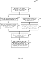
- a method for wireless communication at a UE may include identifying an interference parameter for a first downlink transmission received over a shared radio frequency spectrum band, generating feedback for the first downlink transmission, and sending, to a base station, the feedback along with an indication of the interference parameter.
- identifying the interference parameter may include receiving a transmission status from at least one neighboring base station, and identifying the interference parameter for the first downlink transmission based at least in part on the transmission status. In some examples, the method may include sending, to the base station with the feedback, the transmission status from the at least one neighboring base station. In some examples, identifying the interference parameter may include measuring a signal-to-noise ratio (SNR) associated with the first downlink transmission, and estimating the interference parameter for the first downlink transmission based at least in part on the measured SNR
- SNR signal-to-noise ratio
- an apparatus for wireless communication at a UE may include means for identifying an interference parameter for a first downlink transmission received over a shared radio frequency spectrum band, means for generating feedback for the first downlink transmission, and means for sending, to a base station, the feedback along with an indication of the interference parameter.
- the apparatus may include means for performing one or more aspects of the method described above.
- the apparatus may include a processor and memory coupled to the processor.
- the processor may be configured to identify an interference parameter for a first downlink transmission received over a shared radio frequency spectrum band, generate feedback for the first downlink transmission, and send, to a base station, the feedback along with an indication of the interference parameter.
- the processor may further be configured to perform one or more aspects of the method described above.
- a computer-readable medium for storing instructions executable by a processor.
- the instructions may include instructions to identify an interference parameter for a first downlink transmission received over a shared radio frequency spectrum band, instructions to generate feedback for the first downlink transmission, and instructions to send, to a base station, the feedback along with an indication of the interference parameter.
- the computer-readable medium may store instructions executable by the processor to perform one or more aspects of the method described above.
- the present disclosure generally relates to techniques for handling feedback for downlink transmissions in a shared radio frequency spectrum band.
- a base station may classify feedback received for a downlink transmission over a shared radio frequency spectrum band.
- the feedback may be classified in one of a plurality of feedback categories and may be based at least in part on an interference parameter for the first downlink transmission.
- the base station may also identify an interference parameter for a subsequent downlink transmission and schedule the subsequent downlink transmission based at least in part on feedback classified in a feedback category associated with the identified interference parameter for the subsequent downlink transmission.
- a shared radio frequency spectrum band is used for at least a portion of communications over a wireless communication system.
- the shared radio frequency spectrum band may be used for Long Term Evolution (LTE) or LTE-Advanced (LTE-A) (LTE/LTE-A) communications.
- LTE Long Term Evolution
- LTE-A LTE-Advanced
- LTE/LTE-A LTE-Advanced
- the shared radio frequency spectrum band may be used in combination with, or independent from, a dedicated radio frequency spectrum band.
- the dedicated radio frequency spectrum band may be a radio frequency spectrum band for which transmitting apparatuses may not contend for access because the radio frequency spectrum band is licensed to particular users, such as a licensed radio frequency spectrum band usable for LTE/LTE-A communications.
- the shared radio frequency spectrum band may be a radio frequency spectrum band for which a device may contend for access (e.g., a radio frequency spectrum band that is available for unlicensed use, such as Wi-Fi use, or a radio frequency spectrum band that is available for use by multiple operators in an equally shared or prioritized manner).
- a radio frequency spectrum band for which a device may contend for access e.g., a radio frequency spectrum band that is available for unlicensed use, such as Wi-Fi use, or a radio frequency spectrum band that is available for use by multiple operators in an equally shared or prioritized manner.
- offloading of at least some data traffic to a shared radio frequency spectrum band may provide a cellular operator (e.g., an operator of a public land mobile network (PLMN) or a coordinated set of base stations defining a cellular network, such as an LTE/LTE-A network) with opportunities for enhanced data transmission capacity.
- a shared radio frequency spectrum band may also provide service in areas where access to a dedicated radio frequency spectrum band is unavailable.
- a transmitting apparatus Before communicating over a shared radio frequency spectrum band, a transmitting apparatus may perform a Listen Before Talk (LBT) procedure to gain access to the medium.
- LBT Listen Before Talk
- Such an LBT procedure may include performing a clear channel assessment (CCA) procedure (or extended CCA procedure) to determine whether a channel of the shared radio frequency spectrum band is available.
- CCA clear channel assessment
- CUBS channel usage beacon signal
- indications of the downlink subframes and uplink subframes for which the channel is being reserved may also be broadcast. If it is determined that the channel is not available, a CCA procedure (or extended CCA procedure) may be performed for the channel again at a later time.
- the wireless communication system 100 may include an LTE/LTE-A network.
- LTE/LTE-A networks the term eNB may be used to describe the base stations 105, while the term UE may be used to describe the UEs 115.
- the wireless communication system 100 may be a Heterogeneous LTE/LTE-A network in which different types of eNBs provide coverage for various geographical regions. For example, each eNB or base station 105 may provide communication coverage for a macro cell, a small cell, or other types of cell.
- a macro cell may cover a relatively large geographic area (e.g ., several kilometers in radius) and may allow unrestricted access by UEs with service subscriptions with the network provider.
- a small cell may be a lower-powered base station, as compared with a macro cell that may operate in the same or different ( e.g., dedicated, shared, etc. ) radio frequency spectrum bands as macro cells.
- Small cells may include pico cells, femto cells, and micro cells according to various examples.
- a pico cell may cover a relatively smaller geographic area and may allow unrestricted access by UEs with service subscriptions with the network provider.
- a femto cell also may cover a relatively small geographic area (e.g., a home) and may provide restricted access by UEs having an association with the femto cell (e.g. , UEs in a closed subscriber group (CSG), UEs for users in the home, and the like).
- An eNB for a macro cell may be referred to as a macro eNB.
- An eNB for a small cell may be referred to as a small cell eNB, a pico eNB, a femto eNB or a home eNB.
- An eNB may support one or multiple ( e.g., two, three, four, and the like) cells (e.g., component carriers).
- the wireless communication system 100 may support synchronous or asynchronous operation.
- the base stations may have similar frame timing, and transmissions from different base stations may be approximately aligned in time.
- the base stations may have different frame timing, and transmissions from different base stations may not be aligned in time.
- the techniques described herein may be used for either synchronous or asynchronous operations.
- the communication networks may be packet-based networks that operate according to a layered protocol stack.
- PDCP Packet Data Convergence Protocol
- a Radio Link Control (RLC) layer may perform packet segmentation and reassembly to communicate over logical channels.
- RLC Radio Link Control
- a Medium Access Control (MAC) layer may perform priority handling and multiplexing of logical channels into transport channels.
- the MAC layer may also use Hybrid Automatic Repeat Request (HARQ) to provide retransmission at the MAC layer to improve link efficiency.
- HARQ Hybrid Automatic Repeat Request
- the Radio Resource Control (RRC) protocol layer may provide establishment, configuration, and maintenance of an RRC connection between a UE 115 and the base stations 105 or core network 130 supporting radio bearers for the user plane data.
- RRC Radio Resource Control
- the transport channels may be mapped to physical channels.
- the UEs 115 may be dispersed throughout the wireless communication system 100, and each UE 115 may be stationary or mobile.
- a UE 115 may also include or be referred to by those skilled in the art as a mobile station, a subscriber station, a mobile unit, a subscriber unit, a wireless unit, a remote unit, a mobile device, a wireless device, a wireless communications device, a remote device, a mobile subscriber station, an access terminal, a mobile terminal, a wireless terminal, a remote terminal, a handset, a user agent, a mobile client, a client, or some other suitable terminology.
- a UE 115 may be a cellular phone, a personal digital assistant (PDA), a wireless modem, a wireless communication device, a handheld device, a tablet computer, a laptop computer, a cordless phone, a wireless local loop (WLL) station, or the like.
- PDA personal digital assistant
- a UE may be able to communicate with various types of base stations and network equipment, including macro eNBs, small cell eNBs, relay base stations, and the like.
- the communication links 125 shown in wireless communication system 100 may include downlink transmissions, from a base station 105 to a UE 115, or uplink transmissions, from a UE 115 to a base station 105.
- the downlink transmissions may also be called forward link transmissions, while the uplink transmissions may also be called reverse link transmissions.
- the downlink transmissions may include, for example, a physical downlink shared channel (PDSCH), a physical downlink control channel (PDCCH; e.g., for transmission over a dedicated radio frequency spectrum band), an enhanced PDCCH (EPDCCH; e.g., for transmission over a shared radio frequency spectrum band), or a physical frame format indicator channel (PFFICH).
- PDSCH physical downlink shared channel
- PDCCH physical downlink control channel
- EPDCCH enhanced PDCCH
- PFFICH physical frame format indicator channel
- signaling on a PFFICH may indicate a TDD frame structure of communications over a communication link 125.
- the uplink transmissions may include, for example, a physical uplink shared channel (PUSCH) or a physical uplink control channel (PUCCH).
- the uplink transmissions may also include feedback (e.g ., HARQ feedback) for the downlink transmissions.
- each communication link 125 may include one or more carriers, where each carrier may be a signal made up of multiple sub-carriers (e.g ., waveform signals of different frequencies) modulated according to the various radio technologies described above. Each modulated signal may be sent on a different sub-carrier and may carry control information (e.g., reference signals, control channels, etc. ), overhead information, user data, etc.
- the communication links 125 may transmit bidirectional communications using a frequency domain duplexing (FDD) operation (e.g ., using paired spectrum resources) or a TDD operation ( e.g ., using unpaired spectrum resources).
- FDD frequency domain duplexing
- TDD e.g ., using unpaired spectrum resources
- the wireless communication system 100 may support operation on multiple cells or carriers, a feature which may be referred to as carrier aggregation or dual-connectivity operation.
- a carrier may also be referred to as a component carrier (CC), a layer, a channel, etc.
- CC component carrier
- the terms “carrier,” “component carrier,” “cell,” and “channel” may be used interchangeably herein.
- a UE 115 may be configured with multiple downlink CCs and one or more uplink CCs for carrier aggregation. In each communication direction, one CC may be configured as a primary cell (PCell), and the other CCs may be configured as secondary cells (SCells).
- Carrier aggregation may be used with both FDD and TDD component carriers.
- the wireless communication system 100 may support operation over a dedicated radio frequency spectrum band (e.g., a radio frequency spectrum band for which transmitting apparatuses may not contend for access because the radio frequency spectrum band is licensed to particular users for particular uses, such as a licensed radio frequency spectrum band usable for LTE/LTE-A communications) or a shared radio frequency spectrum band (e.g., a radio frequency spectrum band for which transmitting apparatuses may need to contend for access (e.g., a radio frequency spectrum band that is available for unlicensed use, such as Wi-Fi use, or a radio frequency spectrum band that is available for use by multiple operators in an equally shared or prioritized manner)).
- a dedicated radio frequency spectrum band e.g., a radio frequency spectrum band for which transmitting apparatuses may not contend for access because the radio frequency spectrum band is licensed to particular users for particular uses, such as a licensed radio frequency spectrum band usable for LTE/LTE-A communications
- a shared radio frequency spectrum band e.g., a radio frequency spectrum band for which transmit
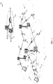
- FIG. 2 shows a wireless communication system 200 in which LTE/LTE-A may be deployed under different scenarios using a shared radio frequency spectrum band, in accordance with various aspects of the present disclosure. More specifically, FIG. 2 illustrates examples of a supplemental downlink mode (also referred to as a licensed assisted access mode), a carrier aggregation mode, and a standalone mode in which LTE/LTE-A is deployed using a shared radio frequency spectrum band.
- the wireless communication system 200 may be an example of portions of the wireless communication system 100 described with reference to FIG. 1 .
- a first base station 205 and a second base station 205-a may be examples of aspects of one or more of the base stations 105 described with reference to FIG.
- a first UE 215, a second UE 215-a, a third UE 215-b, and a fourth UE 215-c may be examples of aspects of one or more of the UEs 115 described with reference to FIG. 1 .
- the first base station 205 may transmit Orthogonal Frequency-Division Multiple Access (OFDMA) waveforms to the first UE 215 using a downlink channel 220.
- the downlink channel 220 may be associated with a frequency F1 in a shared radio frequency spectrum band.
- the first base station 205 may transmit OFDMA waveforms to the first UE 215 using a first bidirectional link 225 and may receive single-carrier frequency-division multiple access (SC-FDMA) waveforms from the first UE 215 using the first bidirectional link 225.
- SC-FDMA single-carrier frequency-division multiple access
- the first bidirectional link 225 may be associated with a frequency F4 in a dedicated radio frequency spectrum band.
- the downlink channel 220 in the shared radio frequency spectrum band and the first bidirectional link 225 in the dedicated radio frequency spectrum band may operate contemporaneously.
- the downlink channel 220 may provide a downlink capacity offload for the first base station 205.
- the downlink channel 220 may be used for unicast services (e.g ., addressed to one UE) or for multicast services (e.g ., addressed to several UEs). This scenario may occur with any service provider (e.g., a mobile network operator (MNO)) that uses a dedicated radio frequency spectrum band and needs to relieve some of the traffic or signaling congestion.
- MNO mobile network operator
- the first base station 205 may transmit OFDMA waveforms to the second UE 215-a using a second bidirectional link 230 and may receive OFDMA waveforms, SC-FDMA waveforms, or resource block interleaved waveforms from the second UE 215-a using the second bidirectional link 230.
- the second bidirectional link 230 may be associated with the frequency F1 in the shared radio frequency spectrum band.
- the first base station 205 may also transmit OFDMA waveforms to the second UE 215-a using a third bidirectional link 235 and may receive SC-FDMA waveforms from the second UE 215-a using the third bidirectional link 235.
- the third bidirectional link 235 may be associated with a frequency F2 in a dedicated radio frequency spectrum band.
- the second bidirectional link 230 may provide a downlink and uplink capacity offload for the first base station 205.
- this scenario may occur with any service provider (e.g ., MNO) that uses a dedicated radio frequency spectrum band and needs to relieve some of the traffic or signaling congestion.
- MNO service provider
- the first base station 205 may transmit OFDMA waveforms to the third UE 215-b using a fourth bidirectional link 240 and may receive OFDMA waveforms, SC-FDMA waveforms, or resource block interleaved waveforms from the third UE 215-b using the fourth bidirectional link 240.
- the fourth bidirectional link 240 may be associated with a frequency F3 in the shared radio frequency spectrum band.
- the first base station 205 may also transmit OFDMA waveforms to the third UE 215-b using a fifth bidirectional link 245 and may receive SC-FDMA waveforms from the third UE 215-b using the fifth bidirectional link 245.
- the fifth bidirectional link 245 may be associated with the frequency F2 in the dedicated radio frequency spectrum band.
- the fourth bidirectional link 240 may provide a downlink and uplink capacity offload for the first base station 205.
- This example and those provided above are presented for illustrative purposes and there may be other similar modes of operation or deployment scenarios that combine LTE/LTE-A in a dedicated radio frequency spectrum band and use a shared radio frequency spectrum band for capacity offload.
- an operational example may include a bootstrapped mode (e.g., supplemental downlink (e.g., LAA), carrier aggregation) that uses the LTE/LTE-A primary component carrier (PCC) on the dedicated radio frequency spectrum band and at least one secondary component carrier (SCC) on the shared radio frequency spectrum band.
- a bootstrapped mode e.g., supplemental downlink (e.g., LAA), carrier aggregation
- PCC primary component carrier
- SCC secondary component carrier
- data and control may, for example, be communicated in the dedicated radio frequency spectrum band (e.g., via first bidirectional link 225, third bidirectional link 235, and fifth bidirectional link 245) while data may, for example, be communicated in the shared radio frequency spectrum band ( e.g., via second bidirectional link 230 and fourth bidirectional link 240).
- the carrier aggregation mechanisms supported when using a shared radio frequency spectrum band may fall under a hybrid FDD-TDD carrier aggregation or a TDD-TDD carrier aggregation with different symmetry across component carriers.
- the second base station 205-a may transmit OFDMA waveforms to the fourth UE 215-c using a bidirectional link 250 and may receive OFDMA waveforms, SC-FDMA waveforms, or resource block interleaved waveforms from the fourth UE 215-c using the bidirectional link 250.
- the bidirectional link 250 may be associated with the frequency F3 in the shared radio frequency spectrum band.
- the standalone mode may be used in non-traditional wireless access scenarios, such as in-stadium access ( e.g ., unicast, multicast).
- An example of a type of service provider for this mode of operation may be a stadium owner, cable company, event host, hotel, enterprise, or large corporation that does not have access to a dedicated radio frequency spectrum band.
- the gating interval may define the application of a contention-based protocol, such as an LBT protocol based on the LBT protocol specified in European Telecommunications Standards Institute (ETSI) (EN 301 893).
- ETSI European Telecommunications Standards Institute
- the gating interval may indicate when a transmitting apparatus needs to perform a contention procedure (e.g., an LBT procedure) such as a CCA procedure.
- the outcome of the CCA procedure may indicate to the transmitting apparatus whether a channel of a shared radio frequency spectrum band is available or in use for the gating interval (also referred to as an LBT radio frame).
- the transmitting apparatus may reserve or use the channel of the shared radio frequency spectrum band during part or all of the LBT radio frame.
- the transmitting apparatus may be prevented from using the channel during the LBT radio frame.
- the channel of the shared radio frequency spectrum band may be reserved by transmitting a CUBS over the shared radio frequency spectrum band.
- FIG. 3 shows a timing diagram 300 of resynchronization operations for base stations communicating with UEs via a fixed LBT radio frame structure (e.g ., an LBT radio frame structure in which LBT radio frames are aligned with a periodic radio frame structure 305), in accordance with various aspects of the present disclosure.
- the base stations may be neighboring base stations of a same PLMN, and may be examples of aspects of the base stations 105, 205, or 205-a described with reference to FIGs. 1 or 2 .
- the UEs may likewise be examples of aspects of the UEs 115, 215, 215-a, 215-b, or 215-c described with reference to FIGs. 1 or 2 .
- the periodic radio frame structure 305 shown in FIG. 3 includes radio frames designated by system frame numbers (SFNs) 4, 5, 6, 7, 8, and 9.
- SFNs system frame numbers
- a resynchronization occasion is provided in each of SFN 4 and SFN 8 (e.g., a first resynchronization occasion 320 is provided in SFN 4, and a second resynchronization occasion 325 is provided in SFN 8).
- the first base station and the second base station may resynchronize their LBT radio frame timings. After the resynchronization performed during the first resynchronization occasion 320, and when each of the first base station and the second base station have data to transmit or receive, each of the first base station and the second base station may contend for access to the shared radio frequency spectrum band. Because the first base station and the second base station belong to the same PLMN and are synchronized, the first base station and the second base station may both win or both lose contention for access to the shared radio frequency spectrum band.
- each of the first base station and the second base station may transmit respective LBT radio frames (e.g., the first base station may transmit the first LBT radio frame 330, and the second base station may transmit the second LBT radio frame 335), at the same time, in a reuse one mode.
- the first base station and the second base station both have data to transmit and are able to win contention for access to the shared radio frequency spectrum band for SFN 6, the first base station and the second base station may continue to operate in a reuse one mode.
- neither the first base station nor the second base station is able to win contention for access to the shared radio frequency spectrum band at the beginning of SFN 6.
- the first base station and the second base station may operate in a time domain multiplexed (TDM) mode with respect to accessing the shared radio frequency spectrum band.
- TDM time domain multiplexed
- the first base station is shown to win contention for access to the shared radio frequency spectrum band partway through SFN 6, and again for SFN 7.
- the second base station may be prevented from winning contention for access to the shared radio frequency spectrum band.
- the first base station may be prevented from winning contention for access to the shared radio frequency spectrum band.
- the first base station and the second base station may once again resynchronize their LBT radio frame timings and operate in a reuse one mode.
- the switching of the first base station and the second base station between operation in a reuse one mode and operation in a TDM mode may affect the interference environments of the base stations. For example, when the first base station operates in a reuse one mode with respect to the second base station, downlink transmissions of the first base station may experience interference from transmissions of the second base station (and from other base stations within the same PLMN). However, when the first base station operates in a TDM mode with respect to the second base station, downlink transmissions of the first base station may not experience interference from transmissions of the second base station (or from other base stations within the same PLMN). These different interference environments may cause variations in the link quality of a UE associated with the first base station (e.g ., CSI feedback and PDSCH decoding success/failure may vary).
- the first base station receives feedback on downlink transmissions from a UE and updates a HARQ outer feedback loop or CSI feedback outer loop of the first base station in response to the feedback, regardless of whether the feedback corresponds to a downlink transmission made in a reuse one mode or a TDM mode, the performance of the first base station may be adversely affected.
- the update of the HARQ outer feedback loop or the CSI outer feedback loop may result in a higher than supported MCS or rank being used for the downlink transmission, which may result in decreased efficiency on the downlink as a result of a UE's failure to decode the second downlink transmission.
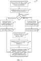
- the aforementioned decreases in efficiency may be mitigated, in some examples, by classifying feedback received for downlink transmissions based at least in part on interference parameters associated with the downlink transmissions, by identifying interference parameters for downlink transmissions, and by scheduling downlink transmissions based on feedback categories associated with the identified interference parameters for the downlink transmissions, as described for example with reference to FIGs. 5 , 6 , 7 , 8 , 9 , 12 , 13 , 14 , or 15 .
- a base station may receive multiple feedback signals associated with a downlink transmission from a UE.
- the multiple feedback signals may be transmitted by multiple UEs or from a single UE.
- one or more of the multiple feedback signals may include an indication of the interference parameter associated with the downlink transmission.
- the multiple signals may not include any information relating to the interference parameter or other parameters associated with the downlink transmission.
- the base station may then classify one or more of the multiple feedback signals based on an interference parameter, which may be determined by the base station or obtained from an indication transmitted by the UE.
- the base station may classify a subset of the multiple feedback signals associated with a downlink transmission from a UE based on whether the feedback signal is associated with a downlink transmission made in a reuse one mode or in a TDM mode. After classifying, the base station may then schedule resources associated with a subsequent downlink transmission for the UE. In some cases, the base station may also update one or more of the HARQ outer feedback loop or the CSI outer feedback loop and the scheduling may involve determining an MCS for the subsequent downlink transmission based on the updated HARQ outer feedback loop or the updated CSI outer feedback loop. By classifying multiple feedback signals in this manner, a base station may be able schedule subsequent downlink transmissions for a UE based on whether the subsequent downlink transmission is to be made in a reuse one mode or a TDM mode, for example.
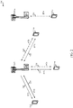
- FIG. 4 shows a timing diagram 400 of resynchronization operations for base stations communicating with UEs via a floating LBT radio frame structure (e.g ., an LBT radio frame structure in which LBT radio frames may not be aligned with a periodic radio frame structure 405), in accordance with various aspects of the present disclosure.
- the base stations may be neighboring base stations of a same PLMN, and may be examples of aspects of the base stations 105, 205, or 205-a described with reference to FIGs. 1 or 2 .
- the UEs may likewise be examples of aspects of the UEs 115, 215, 215-a, 215-b, or 215-c described with reference to FIGs. 1 or 2 .
- FIG. 4 shows a timeline 410 of LBT radio frames transmitted by a first base station over a shared radio frequency spectrum band, and a timeline 415 of LBT radio frames transmitted by a second base station over a shared radio frequency spectrum band, in relation to a periodic radio frame structure 405 associated with a dedicated radio frequency spectrum band.
- the dedicated radio frequency spectrum band may be a radio frequency spectrum band for which transmitting apparatuses may not contend for access because the radio frequency spectrum band is licensed to particular users for particular uses (e.g., a licensed radio frequency spectrum band usable for LTE/LTE-A communications).
- the shared radio frequency spectrum band may be a radio frequency spectrum band for which transmitting apparatuses may need to contend for access (e.g., a radio frequency spectrum band that is available for unlicensed use, such as Wi-Fi use, or a radio frequency spectrum band that is available for use by multiple operators in an equally shared or prioritized manner).
- each of the first base station and the second base station may transmit respective LBT radio frames (e.g., the first base station may transmit the first LBT radio frame 430, and the second base station may transmit the second LBT radio frame 435), at the same time, in a reuse one mode.
- the first base station and the second base station both have data to transmit and are able to win contention for access to the shared radio frequency spectrum band for SFN 6, the first base station and the second base station may continue to operate in a reuse one mode.
- neither the first base station nor the second base station is able to win contention for access to the shared radio frequency spectrum band at the beginning of SFN 6.
- the first base station and the second base station may once again resynchronize their LBT radio frame timings and operate in a reuse one mode.
- the first base station receives feedback on downlink transmissions from a UE and updates a HARQ outer feedback loop or CSI feedback outer loop of the first base station in response to the feedback, regardless of whether the feedback corresponds to a downlink transmission made in a reuse one mode or a TDM mode, the performance of the first base station may be adversely affected.
- the aforementioned decreases in efficiency may be mitigated, in some examples, by classifying feedback received for downlink transmissions based at least in part on interference parameters associated with the downlink transmissions, by identifying interference parameters for downlink transmissions, and by scheduling downlink transmissions based on feedback categories associated with the identified interference parameters for the downlink transmissions, as described for example with reference to FIGs. 5 , 6 , 7 , 8 , 9 , 12 , 13 , 14 , or 15 .
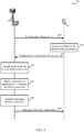
- FIG. 5 shows a communication flow 500 between a base station 505 and a UE 515 over a shared radio frequency spectrum band, in accordance with various aspects of the present disclosure.
- the base station 505 and UE 515 may be examples of aspects of the base stations 105, 205, or 205-a or UEs 115, 215, 215-a, 215-b, or 215-c described with reference to FIGs. 1 or 2 .
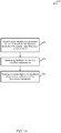
- the communication flow 500 may begin with the base station 505 transmitting a first downlink transmission 520 to the UE 515.
- the UE 515 may generate feedback 530 for the first downlink transmission 520.
- the feedback 530 may be transmitted to the base station 505.
- the base station 505 may classify the feedback 530 in one of a plurality of feedback categories.
- the classification may be based at least in part on an interference parameter for the first downlink transmission.
- the interference parameter may include one of transmission in a reuse one mode or transmission in a TDM mode.
- the base station 505 may identify an interference parameter for a subsequent downlink transmission 550, and at block 545, the base station 505 may schedule the subsequent downlink transmission 550 based at least in part on feedback classified in a feedback category associated with the interference parameter identified at block 535.
- the subsequent downlink transmission 550 may be transmitted to the UE 515.
- the classification of feedback for downlink transmissions, and the scheduling of subsequent transmissions based at least in part on feedback classified in feedback categories associated with interference parameters identified for the subsequent transmissions may improve the efficiency of downlink transmissions by enabling the selection of appropriate MCSs for downlink transmissions associated with different interference parameters.
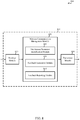
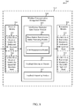
- FIG. 6 shows a block diagram 600 of an apparatus 605 for use in wireless communication, in accordance with various aspects of the present disclosure.
- the apparatus 605 may be an example of aspects of one or more of the base stations 105, 205, 205-a, or 505 described with reference to FIGs. 1 , 2 , or 5 .
- the apparatus 605 may also be or include a processor.
- the apparatus 605 may include a receiver module 610, a wireless communication management module 620, or a transmitter module 630. Each of these modules may be in communication with each other.
- the modules of the apparatus 605 may, individually or collectively, be implemented using one or more application-specific integrated circuits (ASICs) adapted to perform some or all of the applicable functions in hardware. Alternatively, the functions may be performed by one or more other processing units (or cores), on one or more integrated circuits. In other examples, other types of integrated circuits may be used (e.g., Structured/Platform ASICs, Field Programmable Gate Arrays (FPGAs), a System on Chip (SoC), or other Semi-Custom ICs), which may be programmed in any manner known in the art.
- the functions of each module may also be implemented, in whole or in part, with instructions embodied in a memory, formatted to be executed by one or more general or application-specific processors.
- the receiver module 610 may include at least one radio frequency (RF) receiver, such as at least one RF receiver operable to receive transmissions over a dedicated radio frequency spectrum band (e.g., a radio frequency spectrum band for which transmitting apparatuses may not contend for access because the radio frequency spectrum band is licensed to particular users for particular uses, such as a licensed radio frequency spectrum band usable for LTE/LTE-A communications) or a shared radio frequency spectrum band (e.g., a radio frequency spectrum band for which transmitting apparatuses may need to contend for access (e.g., a radio frequency spectrum band that is available for unlicensed use, such as Wi-Fi use, or a radio frequency spectrum band that is available for use by multiple operators in an equally shared or prioritized manner)).
- a dedicated radio frequency spectrum band e.g., a radio frequency spectrum band for which transmitting apparatuses may not contend for access because the radio frequency spectrum band is licensed to particular users for particular uses, such as a licensed radio frequency spectrum band usable for LTE/LTE-A communications
- the wireless communication management module 620 may be used to manage one or more aspects of wireless communication for the apparatus 605, including the transmission of downlink transmissions (e.g ., a first downlink transmission or a subsequent downlink transmission) via the transmitter module 630 over the shared radio frequency spectrum band, and the receipt of feedback for the downlink transmissions via the receiver module 610 over the shared radio frequency spectrum band.
- the wireless communication management module 620 may include a feedback classification module 635, an interference parameter identification module 640, or a downlink scheduling module 645. In some examples, portions of the wireless communication management module 620 may be incorporated into the receiver module 610 or the transmitter module 630.
- the feedback classification module 635 may be used to classify feedback received for the first downlink transmission over the shared radio frequency spectrum band.
- the feedback may be classified in one of a plurality of feedback categories, and may be based at least in part on an interference parameter for the first downlink transmission.
- the interference parameter for the first downlink transmission may include one of transmission in a reuse one mode or transmission in a TDM mode.
- the feedback received for the first downlink transmission may include CSI, ACK/NACK feedback, or a combination thereof.
- the interference parameter identification module 640 may be used to identify an interference parameter for the subsequent downlink transmission.
- the downlink scheduling module 645 may be used to schedule the subsequent downlink transmission based at least in part on feedback classified in a feedback category associated with the identified interference parameter for the subsequent downlink transmission.
- the receiver module 710 may include at least one RF receiver, such as at least one RF receiver operable to receive transmissions over a dedicated radio frequency spectrum band (e.g., a radio frequency spectrum band for which transmitting apparatuses may not contend for access because the radio frequency spectrum band is licensed to particular users for particular uses, such as a licensed radio frequency spectrum band usable for LTE/LTE-A communications) or a shared radio frequency spectrum band (e.g., a radio frequency spectrum band for which transmitting apparatuses may need to contend for access (e.g., a radio frequency spectrum band that is available for unlicensed use, such as Wi-Fi use, or a radio frequency spectrum band that is available for use by multiple operators in an equally shared or prioritized manner)).
- a dedicated radio frequency spectrum band e.g., a radio frequency spectrum band for which transmitting apparatuses may not contend for access because the radio frequency spectrum band is licensed to particular users for particular uses, such as a licensed radio frequency spectrum band usable for LTE/LTE-A communications
- the dedicated radio frequency spectrum band or the shared radio frequency spectrum band may be used for LTE/LTE-A communications, as described, for example, with reference to FIGs. 1 , 2 , 3 , 4 , or 5 .
- the receiver module 710 may in some cases include separate receivers for the dedicated radio frequency spectrum band and the shared radio frequency spectrum band.
- the separate receivers may, in some examples, take the form of an LTE/LTE-A receiver module for communicating over the dedicated radio frequency spectrum band (e.g ., LTE/LTE-A receiver module for dedicated RF spectrum band 712), and an LTE/LTE-A receiver module for communicating over the shared radio frequency spectrum band ( e.g ., LTE/LTE-A receiver module for shared RF spectrum band 714).
- the receiver module 710 including the LTE/LTE-A receiver module for dedicated RF spectrum band 712 or the LTE/LTE-A receiver module for shared RF spectrum band 714, may be used to receive various types of data or control signals (i.e., transmissions) over one or more communication links of a wireless communication system, such as one or more communication links of the wireless communication system 100 or 200 described with reference to FIGs. 1 or 2 .
- the communication links may be established over the dedicated radio frequency spectrum band or the shared radio frequency spectrum band.
- the transmitter module 730 may include at least one RF transmitter, such as at least one RF transmitter operable to transmit over the dedicated radio frequency spectrum band or the shared radio frequency spectrum band.
- the transmitter module 730 may in some cases include separate transmitters for the dedicated radio frequency spectrum band and the shared radio frequency spectrum band.
- the separate transmitters may, in some examples, take the form of an LTE/LTE-A transmitter module for communicating over the dedicated radio frequency spectrum band (e.g ., LTE/LTE-A transmitter module for dedicated RF spectrum band 732), and an LTE/LTE-A transmitter module for communicating over the shared radio frequency spectrum band (e.g ., LTE/LTE-A transmitter module for shared RF spectrum band 734).
- the transmitter module 730 including the LTE/LTE-A transmitter module for dedicated RF spectrum band 732 or the LTE/LTE-A transmitter module for shared RF spectrum band 734, may be used to transmit various types of data or control signals (i.e., transmissions) over one or more communication links of a wireless communication system, such as one or more communication links of the wireless communication system 100 or 200 described with reference to FIGs. 1 or 2 .
- the communication links may be established over the dedicated radio frequency spectrum band or the shared radio frequency spectrum band.
- the wireless communication management module 720 may be used to manage one or more aspects of wireless communication for the apparatus 705, including the transmission of downlink transmissions via the transmitter module 730 over the shared radio frequency spectrum band, and the receipt of feedback for the downlink transmissions via the receiver module 710.
- the feedback for the downlink transmissions may include CSI, ACK/NACK feedback, or a combination thereof.
- the wireless communication management module 720 may include a feedback classification module 735, an interference parameter identification module 740, a downlink scheduling module 745, or a feedback outer loop maintenance module 760. In some examples, portions of the wireless communication management module 720 may be incorporated into the receiver module 710 or the transmitter module 730.
- the interference parameter identification module 740 may be used to identify an interference parameter for a downlink transmission.
- the interference parameter for the downlink transmission may include one of transmission in a reuse one mode or transmission in a TDM mode.
- the interference parameter identification module 740 may include an indication processing module 750 or a base station transmission status processing module 755.
- the indication processing module 750 may be used to receive an indication of the interference parameter for a downlink transmission with feedback for the downlink transmission.
- the base station transmission status processing module 755 may be used to receive a transmission status from at least one other base station and identify the interference parameter for a downlink transmission based at least in part on the transmission status.
- the transmission status may be a transmission status that existed at a time when the downlink transmission was transmitted.
- the apparatus 705 and the at least one other base station from which a transmission status is received may belong to a same PLMN.
- receiving a transmission status may include receiving a CUBS, or a PFFICH, or a combination thereof.
- the downlink scheduling module 745 may be used to schedule a downlink transmission (e.g ., select an MCS for the downlink transmission) based at least in part on feedback classified in a feedback category associated with the interference parameter identified for the downlink transmission.
- the feedback category may be the first feedback category.
- the interference parameter identified for the subsequent downlink transmission includes transmission in a TDM mode
- the feedback category may be the second feedback category.
- the downlink scheduling module 745 may perform downlink scheduling per subframe.
- the feedback outer loop maintenance module 760 may be used to maintain, for each feedback category of the plurality of feedback categories, at least one of a separate HARQ feedback outer loop or a separate CSI feedback outer loop. In some examples, the feedback outer loop maintenance module 760 may skip, upon classifying the feedback received for a downlink transmission in a first feedback category, at least one update of at least one of: a HARQ feedback outer loop associated with a second feedback category or a CSI feedback outer loop associated with the second feedback category. The feedback outer loop maintenance module 760 may also skip, upon classifying the feedback received for a downlink transmission in the second feedback category, at least one update of at least one of: a HARQ feedback outer loop associated with the first feedback category or a CSI feedback outer loop associated with the first feedback category.
- the downlink scheduling module 745 may be used to schedule a downlink transmission based at least in part on one or both of a HARQ feedback outer loop and a CSI feedback outer loop associated with a feedback category associated with an interference parameter for the downlink transmission.
- FIG. 8 shows a block diagram 800 of an apparatus 815 for use in wireless communication, in accordance with various aspects of the present disclosure.
- the apparatus 815 may be an example of aspects of one or more of the UEs 115, 215, 215-a, 215-b, 215-c, or 515 described with reference to FIGs. 1 , 2 , or 5 .
- the apparatus 815 may also be or include a processor.
- the apparatus 815 may include a receiver module 810, a wireless communication management module 820, or a transmitter module 830. Each of these modules may be in communication with each other.
- the modules of the apparatus 815 may, individually or collectively, be implemented using one or more ASICs adapted to perform some or all of the applicable functions in hardware. Alternatively, the functions may be performed by one or more other processing units (or cores), on one or more integrated circuits. In other examples, other types of integrated circuits may be used (e.g ., Structured/Platform ASICs, FPGAs, a SoC, or other Semi-Custom ICs), which may be programmed in any manner known in the art.
- the functions of each module may also be implemented, in whole or in part, with instructions embodied in a memory, formatted to be executed by one or more general or application-specific processors.
- the receiver module 810 may include at least one RF receiver, such as at least one RF receiver operable to receive transmissions over a dedicated radio frequency spectrum band (e.g., a radio frequency spectrum band for which transmitting apparatuses may not contend for access because the radio frequency spectrum band is licensed to particular users for particular uses, such as a licensed radio frequency spectrum band usable for LTE/LTE-A communications) or a shared radio frequency spectrum band (e.g., a radio frequency spectrum band for which transmitting apparatuses may need to contend for access (e.g., a radio frequency spectrum band that is available for unlicensed use, such as Wi-Fi use, or a radio frequency spectrum band that is available for use by multiple operators in an equally shared or prioritized manner)).
- a dedicated radio frequency spectrum band e.g., a radio frequency spectrum band for which transmitting apparatuses may not contend for access because the radio frequency spectrum band is licensed to particular users for particular uses, such as a licensed radio frequency spectrum band usable for LTE/LTE-A communications
- the dedicated radio frequency spectrum band or the shared radio frequency spectrum band may be used for LTE/LTE-A communications, as described, for example, with reference to FIGs. 1 , 2 , 3 , 4 , or 5 .
- the receiver module 810 may be used to receive various types of data or control signals (i.e., transmissions) over one or more communication links of a wireless communication system, such as one or more communication links of the wireless communication systems 100 or 200 described with reference to FIGs. 1 or 2 .
- the communication links may be established over the first radio frequency spectrum band or the second radio frequency spectrum band.
- the transmitter module 830 may include at least one RF transmitter, such as at least one RF transmitter operable to transmit over the dedicated radio frequency spectrum band or the shared radio frequency spectrum band.
- the transmitter module 830 may be used to transmit various types of data or control signals ( i.e., transmissions) over one or more communication links of a wireless communication system, such as one or more communication links of the wireless communication system 100 or 200 described with reference to FIGs. 1 or 2 .
- the communication links may be established over the dedicated radio frequency spectrum band or the shared radio frequency spectrum band.
- the wireless communication management module 820 may be used to manage one or more aspects of wireless communication for the apparatus 815, including the receipt of downlink transmissions via the receiver module 810 over the shared radio frequency spectrum band, and the sending of feedback for the downlink transmissions via the transmitter module 830.
- the wireless communication management module 820 may include an interference parameter identification module 835, a feedback generation module 840, or a feedback reporting module 845.
- portions of the wireless communication management module 820 may be incorporated into the receiver module 810 or the transmitter module 830.
- the interference parameter identification module 835 may be used to identify an interference parameter for a first downlink transmission received over a shared radio frequency spectrum band.
- the interference parameter for the first downlink transmission may include one of transmission in a reuse one mode or transmission in a TDM mode.
- the feedback generation module 840 may be used to generate feedback for the first downlink transmission.
- the feedback generated for the first downlink transmission may include CSI, ACK/NACK feedback, or a combination thereof.
- the feedback reporting module 845 may be used to send the feedback, along with an indication of the interference parameter, to a base station.
- FIG. 9 shows a block diagram 900 of an apparatus 915 for use in wireless communication, in accordance with various aspects of the present disclosure.
- the apparatus 915 may be an example of aspects of one or more of the UEs 115, 215, 215-a, 215-b, 215-c, or 515 described with reference to FIGs. 1 , 2 , or 5 , or aspects of the apparatus 815 described with reference to FIG. 8 .
- the apparatus 915 may also be or include a processor.
- the apparatus 915 may include a receiver module 910, a wireless communication management module 920, or a transmitter module 930. Each of these modules may be in communication with each other.
- the modules of the apparatus 915 may, individually or collectively, be implemented using one or more ASICs adapted to perform some or all of the applicable functions in hardware. Alternatively, the functions may be performed by one or more other processing units (or cores), on one or more integrated circuits. In other examples, other types of integrated circuits may be used (e.g ., Structured/Platform ASICs, FPGAs, a SoC, or other Semi-Custom ICs), which may be programmed in any manner known in the art.
- the functions of each module may also be implemented, in whole or in part, with instructions embodied in a memory, formatted to be executed by one or more general or application-specific processors.
- the receiver module 910 may include at least one RF receiver, such as at least one RF receiver operable to receive transmissions over a dedicated radio frequency spectrum band (e.g., a radio frequency spectrum band for which transmitting apparatuses may not contend for access because the radio frequency spectrum band is licensed to particular users for particular uses, such as a licensed radio frequency spectrum band usable for LTE/LTE-A communications) or a shared radio frequency spectrum band (e.g., a radio frequency spectrum band for which transmitting apparatuses may need to contend for access (e.g., a radio frequency spectrum band that is available for unlicensed use, such as Wi-Fi use, or a radio frequency spectrum band that is available for use by multiple operators in an equally shared or prioritized manner)).
- a dedicated radio frequency spectrum band e.g., a radio frequency spectrum band for which transmitting apparatuses may not contend for access because the radio frequency spectrum band is licensed to particular users for particular uses, such as a licensed radio frequency spectrum band usable for LTE/LTE-A communications
- the dedicated radio frequency spectrum band or the shared radio frequency spectrum band may be used for LTE/LTE-A communications, as described, for example, with reference to FIGs. 1 , 2 , 3 , 4 , or 5 .
- the receiver module 910 may in some cases include separate receivers for the dedicated radio frequency spectrum band and the shared radio frequency spectrum band.
- the separate receivers may, in some examples, take the form of an LTE/LTE-A receiver module for communicating over the dedicated radio frequency spectrum band (e.g ., LTE/LTE-A receiver module for dedicated RF spectrum band 912), and an LTE/LTE-A receiver module for communicating over the shared radio frequency spectrum band ( e.g ., LTE/LTE-A receiver module for shared RF spectrum band 914).
- the receiver module 910 including the LTE/LTE-A receiver module for dedicated RF spectrum band 912 or the LTE/LTE-A receiver module for shared RF spectrum band 914, may be used to receive various types of data or control signals ( i.e., transmissions) over one or more communication links of a wireless communication system, such as one or more communication links of the wireless communication system 100 or 200 described with reference to FIGs. 1 or 2 .
- the communication links may be established over the dedicated radio frequency spectrum band or the shared radio frequency spectrum band.
- the transmitter module 930 may include at least one RF transmitter, such as at least one RF transmitter operable to transmit over the dedicated radio frequency spectrum band or the shared radio frequency spectrum band.
- the transmitter module 930 may in some cases include separate transmitters for the dedicated radio frequency spectrum band and the shared radio frequency spectrum band.
- the separate transmitters may, in some examples, take the form of an LTE/LTE-A transmitter module for communicating over the dedicated radio frequency spectrum band (e.g ., LTE/LTE-A transmitter module for dedicated RF spectrum band 932), and an LTE/LTE-A transmitter module for communicating over the shared radio frequency spectrum band (e.g ., LTE/LTE-A transmitter module for shared RF spectrum band 934).
- the transmitter module 930 including the LTE/LTE-A transmitter module for dedicated RF spectrum band 932 or the LTE/LTE-A transmitter module for shared RF spectrum band 934, may be used to transmit various types of data or control signals (i.e., transmissions) over one or more communication links of a wireless communication system, such as one or more communication links of the wireless communication system 100 or 200 described with reference to FIGs. 1 or 2 .
- the communication links may be established over the dedicated radio frequency spectrum band or the shared radio frequency spectrum band.
- the wireless communication management module 920 may be used to manage one or more aspects of wireless communication for the apparatus 915, including the receipt of downlink transmissions via the receiver module 910 over the shared radio frequency spectrum band, and the sending of feedback for the downlink transmissions via the transmitter module 930.
- the wireless communication management module 920 may include an interference parameter identification module 935, a feedback generation module 940, or a feedback reporting module 945.
- portions of the wireless communication management module 920 may be incorporated into the receiver module 910 or the transmitter module 930.
- the apparatus 915 and the at least one neighboring base station may belong to a same PLMN.
- the SNR measurement module 955 may be used to measure a SNR associated with the first downlink transmission estimate the interference parameter for the first downlink transmission based at least in part on the measured SNR
- the feedback generation module 940 may be used to generate feedback for the first downlink transmission.
- the feedback generated for the first downlink transmission may include CSI, ACK/NACK feedback, or a combination thereof.
- the feedback reporting module 945 may be used to send the feedback, along with an indication of the interference parameter, to a base station. In some examples, the feedback reporting module 945 may also send the transmission status from the at least one neighboring base station to the base station with the feedback.
- FIG. 10 shows a block diagram 1000 of a base station 1005 (e.g., a base station forming part or all of an eNB) for use in wireless communication, in accordance with various aspects of the present disclosure.
- the base station 1005 may be an example of one or more aspects of the base station 105, 205, 205-a, or 505 described with reference to FIGs. 1 , 2 , or 5 , or aspects of one or more of the apparatus 605 or 705 described with reference to FIGs. 6 or 7 .
- the base station 1005 may be configured to implement or facilitate at least some of the base station features and functions described with reference to FIGs. 1 , 2 , 3 , 4 , 5 , 6 , or 7 .
- the base station 1005 may include a base station processor module 1010, a base station memory module 1020, at least one base station transceiver module (represented by base station transceiver module(s) 1050), at least one base station antenna (represented by base station antenna(s) 1055), or a base station wireless communication management module 1060.
- the base station 1005 may also include one or more of a base station communications module 1030 or a network communications module 1040. Each of these components may be in communication with each other, directly or indirectly, over one or more buses 1035.
- the base station memory module 1020 may include random access memory (RAM) or read-only memory (ROM).
- the base station memory module 1020 may store computer-readable, computer-executable code 1025 containing instructions that are configured to, when executed, cause the base station processor module 1010 to perform various functions described herein related to wireless communication, including the classification of feedback received for downlink transmissions, and the scheduling of downlink transmissions based at least in part on classified feedback.
- the code 1025 may not be directly executable by the base station processor module 1010 but be configured to cause the base station 1005 ( e.g., when compiled and executed) to perform various of the functions described herein.
- the base station processor module 1010 may include an intelligent hardware device, e.g., a CPU, a microcontroller, an ASIC, etc.
- the base station processor module 1010 may process information received through the base station transceiver module(s) 1050, the base station communications module 1030, or the network communications module 1040.
- the base station processor module 1010 may also process information to be sent to the transceiver module(s) 1050 for transmission through the antenna(s) 1055, to the base station communications module 1030, for transmission to one or more other base stations 1005-a and 1005-b, or to the network communications module 1040 for transmission to a core network 1045, which may be an example of one or more aspects of the core network 130 described with reference to FIG. 1 .
- the base station processor module 1010 may handle, alone or in connection with the base station wireless communication management module 1060, various aspects of communicating over (or managing communications over) a dedicated radio frequency spectrum band or a shared radio frequency spectrum band.
- the dedicated radio frequency spectrum band may include a radio frequency spectrum band for which transmitting apparatuses may not contend for access (e.g., a radio frequency spectrum band licensed to particular users for particular uses, such as a licensed radio frequency spectrum band usable for LTE/LTE-A communications).
- the shared radio frequency spectrum band may include a radio frequency spectrum band for which transmitting apparatuses may need to contend for access (e.g., a radio frequency spectrum band that is available for unlicensed use, such as Wi-Fi use, or a radio frequency spectrum band that is available for use by multiple operators in an equally shared or prioritized manner).
- a radio frequency spectrum band for which transmitting apparatuses may need to contend for access e.g., a radio frequency spectrum band that is available for unlicensed use, such as Wi-Fi use, or a radio frequency spectrum band that is available for use by multiple operators in an equally shared or prioritized manner.
- the base station transceiver module(s) 1050 may include a modem configured to modulate packets and provide the modulated packets to the base station antenna(s) 1055 for transmission, and to demodulate packets received from the base station antenna(s) 1055.
- the base station transceiver module(s) 1050 may, in some examples, be implemented as one or more base station transmitter modules and one or more separate base station receiver modules.
- the base station transceiver module(s) 1050 may support communications in the dedicated radio frequency spectrum band or the shared radio frequency spectrum band.
- the base station transceiver module(s) 1050 may be configured to communicate bi-directionally, via the antenna(s) 1755, with one or more UEs or apparatuses, such as one or more of the UEs 115, 215, 215-a, 215-b, 215-c, or 515 described with reference to FIGs. 1 , 2 , or 5 , or one or more of the apparatus 815 or 915 described with reference to FIGs. 8 or 9 .
- the base station 1005 may, for example, include multiple base station antennas 1055 ( e.g., an antenna array).
- the base station 1005 may communicate with the core network 1045 through the network communications module 1040.
- the base station 1005 may also communicate with other base stations, such as the base stations 1005-a and 1005-b, using the base station communications module 1030.
- the base station wireless communication management module 1060 may include a base station LTE/LTE-A module for dedicated RF spectrum band 1065 configured to handle LTE/LTE-A communications in the dedicated radio frequency spectrum band, and a base station LTE/LTE-A module for shared RF spectrum band 1070 configured to handle LTE/LTE-A communications in the shared radio frequency spectrum band.
- the base station wireless communication management module 1060, or portions of it, may include a processor, or some or all of the functions of the base station wireless communication management module 1060 may be performed by the base station processor module 1010 or in connection with the base station processor module 1010.
- the base station wireless communication management module 1060 may be an example of the wireless communication management module 620 or 720 described with reference to FIG. 6 or 7 .
- FIG. 11 shows a block diagram 1100 of a UE 1115 for use in wireless communication, in accordance with various aspects of the present disclosure.
- the UE 1115 may have various configurations and may be included or be part of a personal computer (e.g ., a laptop computer, a netbook computer, a tablet computer, etc .), a cellular telephone, a PDA, a digital video recorder (DVR), an internet appliance, a gaming console, an e-reader, etc.
- the UE 1115 may, in some examples, have an internal power supply (not shown), such as a small battery, to facilitate mobile operation.
- the UE 1115 may be an example of aspects of one or more of the UEs 115, 215, 215-a, 215-b, 215-c, or 515 described with reference to FIGs. 1 , 2 , or 5 , or aspects of one or more of the apparatuses 605 or 705 described with reference to FIGs. 6 or 7 .
- the UE 1115 may be configured to implement at least some of the UE or apparatus features and functions described with reference to FIGs. 1 , 2 , 3 , 4 , 5 , 8 , or 9 .
- the UE 1115 may include a UE processor module 1110, a UE memory module 1120, at least one UE transceiver module (represented by UE transceiver module(s) 1130), at least one UE antenna (represented by UE antenna(s) 1140), or a UE wireless communication management module 1160. Each of these components may be in communication with each other, directly or indirectly, over one or more buses 1135.
- the UE memory module 1120 may include RAM or ROM.
- the UE memory module 1120 may store computer-readable, computer-executable code 1125 containing instructions that are configured to, when executed, cause the UE processor module 1110 to perform various functions described herein related to wireless communication, including the reporting of feedback for downlink transmissions.
- the code 1125 may not be directly executable by the UE processor module 1110 but be configured to cause the UE 1115 ( e.g ., when compiled and executed) to perform various of the functions described herein.
- the UE processor module 1110 may include an intelligent hardware device, e.g., a central processing unit (CPU), a microcontroller, an ASIC, etc.
- the UE processor module 1110 may process information received through the UE transceiver module(s) 1130 or information to be sent to the UE transceiver module(s) 1130 for transmission through the UE antenna(s) 1140.
- the UE processor module 1110 may handle, alone or in connection with the UE wireless communication management module 1160, various aspects of communicating over (or managing communications over) a dedicated radio frequency spectrum band or a shared radio frequency spectrum band.
- the UE transceiver module(s) 1130 may include a modem configured to modulate packets and provide the modulated packets to the UE antenna(s) 1140 for transmission, and to demodulate packets received from the UE antenna(s) 1140.
- the UE transceiver module(s) 1130 may, in some examples, be implemented as one or more UE transmitter modules and one or more separate UE receiver modules.
- the UE transceiver module(s) 1130 may support communications in the licensed radio frequency spectrum band or the unlicensed radio frequency spectrum band.
- the UE transceiver module(s) 1130 may be configured to communicate bi-directionally, via the UE antenna(s) 1140, with one or more of the base stations 105, 205, 205-a, 505, or 1005 described with reference to FIGs. 1 , 2 , 5 , or 10 , or one or more of the apparatuses 605 or 705 described with reference to FIGs. 6 or 7 . While the UE 1115 may include a single UE antenna, there may be examples in which the UE 1115 may include multiple UE antennas 1140.
- the UE wireless communication management module 1160 may be configured to perform or control some or all of the UE or apparatus features or functions described with reference to FIGs. 1 , 2 , 3 , 4 , 5 , 8 , or 9 related to wireless communication over the dedicated radio frequency spectrum band or the shared radio frequency spectrum band.
- the UE wireless communication management module 1160 may be configured to support a supplemental downlink mode (e.g., a licensed assisted access mode), a carrier aggregation mode, or a standalone mode using the dedicated radio frequency spectrum band or the shared radio frequency spectrum band.
- the UE wireless communication management module 1160 may include a UE LTE/LTE-A module for dedicated RF spectrum band 1165 configured to handle LTE/LTE-A communications in the dedicated radio frequency spectrum band, and a UE LTE/LTE-A module for shared RF spectrum band 1170 configured to handle LTE/LTE-A communications in the shared radio frequency spectrum band.
- the UE wireless communication management module 1160, or portions of it, may include a processor, or some or all of the functions of the UE wireless communication management module 1160 may be performed by the UE processor module 1110 or in connection with the UE processor module 1110.
- the UE wireless communication management module 1160 may be an example of the wireless communication management module 820 or 920 described with reference to FIGs. 8 or 9 .
- FIG. 12 is a flow chart illustrating an example of a method 1200 for wireless communication, in accordance with various aspects of the present disclosure.
- the method 1200 is described below with reference to aspects of one or more of the base stations 105, 205, 205-a, 505, or 1005 described with reference to FIGs. 1 , 2 , 5 , or 10 , or aspects of the apparatus 605 or 705 described with reference to FIGs. 6 or 7 .
- a base station or apparatus may execute one or more sets of codes to control the functional elements of the base station or apparatus to perform the functions described below. Additionally or alternatively, the base station or apparatus may perform one or more of the functions described below using special-purpose hardware.
- the method 1200 may include classifying feedback received for a first downlink transmission over a shared radio frequency spectrum band.
- the feedback may be classified in one of a plurality of feedback categories, and may be based at least in part on an interference parameter for the first downlink transmission.
- the shared radio frequency spectrum band may include a radio frequency spectrum band for which transmitting apparatuses may need to contend for access (e.g., a radio frequency spectrum band that is available for unlicensed use, such as Wi-Fi use, or a radio frequency spectrum band that is available for use by multiple operators in an equally shared or prioritized manner).
- the method 1200 may include scheduling the subsequent downlink transmission based at least in part on feedback classified in a feedback category associated with the identified interference parameter for the subsequent downlink transmission.
- the operation(s) at block 1215 may be performed using the wireless communication management module 620 or 1060 described with reference to FIGs. 6 , 7 , or 10 , or the downlink scheduling module 645 described with reference to FIGs. 6 or 7 .
- the method 1200 may provide for wireless communication. It should be noted that the method 1200 is just one implementation and that the operations of the method 1200 may be rearranged or otherwise modified such that other implementations are possible.
- the base station or apparatus performing the method 1300 and the at least one other base station from which a transmission status is received may belong to a same PLMN.
- receiving a transmission status may include receiving a CUBS, or a PFFICH, or a combination thereof.
- the operation(s) at block 1310 may be performed using the wireless communication management module 620 or 1060 described with reference to FIGs. 6 , 7 , or 10 , the interference parameter identification module 640 described with reference to FIGs. 6 or 7 , or the indication processing module 750 or base station transmission status processing module 755 described with reference to FIG. 7 .
- the method 1300 may branch to block 1320 or 1325 based at least in part on the interference parameter for the first downlink transmission.
- the interference parameter includes transmission in a reuse one mode
- the method 1300 may continue at block 1320.
- the interference parameter includes transmission in a TDM mode
- the method 1300 may continue at block 1325.
- the method 1300 may include classifying feedback received for the first downlink transmission in a first feedback category 1330 based at least in part on the interference parameter for the first downlink transmission including transmission of the first downlink transmission in a reuse one mode.
- the method 1300 may include classifying feedback received for the first downlink transmission in a second feedback category 1335 based at least in part on the interference parameter for the first downlink transmission including transmission of the first downlink transmission in a TDM mode.
- the method 1300 may include maintaining, for each feedback category of the plurality of feedback categories, at least one of a separate HARQ feedback outer loop or a separate CSI feedback outer loop.
- the operation(s) at block 1315, 1320, or 1325 may be performed using the wireless communication management module 620 or 1060 described with reference to FIGs. 6 , 7 , or 10 , or the feedback classification module 635 described with reference to FIGs. 6 or 7 .
- the maintenance of feedback outer loops may be performed using the wireless communication management module 620 or 1060 described with reference to FIGs. 6 , 7 , or 10 , or the feedback outer loop maintenance module 760 described with reference to FIG. 7 .
- the operation(s) at block 1305, 1310, 1315, 1320, or 1325 may be performed for each of a plurality of downlink transmissions.
- the method 1300 may optionally include receiving a transmission status from at least one other base station.
- the base station or apparatus performing the method 1300 and the at least one other base station may belong to a same PLMN.
- receiving a transmission status may include receiving a CUBS, or a PFFICH, or a combination thereof.
- the operation(s) at block 1340 may be performed using the wireless communication management module 620 or 1060 described with reference to FIGs. 6 , 7 , or 10 , the interference parameter identification module 640 or 740 described with reference to FIGs. 6 or 7 , or the base station transmission status processing module 755 described with reference to FIG. 7 .
- the method 1300 may include identifying an interference parameter for a subsequent downlink transmission.
- the interference parameter for the subsequent downlink transmission may include one of transmission in a reuse one mode or transmission in a TDM mode.
- identifying the interference parameter for the subsequent downlink transmission may include identifying the interference parameter for the subsequent downlink transmission based at least in part on the transmission status received at block 1340.
- the transmission status may be a transmission status that exists at a time when the subsequent downlink transmission is transmitted.
- the base station or apparatus performing the method 1300 and the at least one other base station may belong to a same PLMN.
- the operation(s) at block 1345 may be performed using the wireless communication management module 620 or 1060 described with reference to FIGs. 6 , 7 , or 10 , the interference parameter identification module 640 described with reference to FIGs. 6 or 7 , or the indication processing module 750 or base station transmission status processing module 755 described with reference to FIG. 7 .
- the method 1300 may include scheduling the subsequent downlink transmission (e.g ., selecting an MCS for the subsequent downlink transmission) based at least in part on feedback classified in a feedback category associated with the interference parameter identified for the subsequent downlink transmission at block 1345.
- the feedback category may be the first feedback category 1330.
- the interference parameter identified for the subsequent downlink transmission includes transmission in a TDM mode
- the feedback category may be the second feedback category 1335.
- the scheduling may be performed per subframe.
- the operation(s) at block 1350 may be performed using the wireless communication management module 620 or 1060 described with reference to FIGs. 6 , 7 , or 10 , or the downlink scheduling module 645 described with reference to FIGs. 6 or 7 .
- the subsequent downlink transmission may be scheduled based at least in part on one or both of a HARQ feedback outer loop and a CSI feedback outer loop associated with the feedback category associated with the interference parameter for the subsequent downlink transmission.
- the method 1300 may include skipping, upon classifying the feedback received for the first downlink transmission in the first feedback category, at least one update of at least one of: a HARQ feedback outer loop associated with the second feedback category or a CSI feedback outer loop associated with the second feedback category.
- the method 1300 may also include skipping, upon classifying the feedback received for the first downlink transmission in the second feedback category, at least one update of at least one of: a HARQ feedback outer loop associated with the first feedback category or a CSI feedback outer loop associated with the first feedback category.
- the method 1300 may provide for wireless communication. It should be noted that the method 1300 is just one implementation and that the operations of the method 1300 may be rearranged or otherwise modified such that other implementations are possible.
- FIG. 14 is a flow chart illustrating an example of a method 1400 for wireless communication, in accordance with various aspects of the present disclosure.
- the method 1400 is described below with reference to aspects of one or more of the UEs 115, 215, 215-a, 215-b, 215-c, 515, or 1115 described with reference to FIGs. 1 , 2 , 5 , or 11 , or aspects of the apparatus 815 or 915 described with reference to FIGs. 8 or 9 .
- a UE or apparatus may execute one or more sets of codes to control the functional elements of the UE or apparatus to perform the functions described below. Additionally or alternatively, the UE or apparatus may perform one or more of the functions described below using special-purpose hardware.
- the method 1400 may include generating feedback for the first downlink transmission.
- the feedback generated for the first downlink transmission may include CSI, ACK/NACK feedback, or a combination thereof.
- the operation(s) at block 1410 may be performed using the wireless communication management module 820 or 1160 described with reference to FIGs. 8 , 9 , or 11 , or the feedback generation module 840 described with reference to FIGs. 8 or 9 .
- the method 1400 may provide for wireless communication. It should be noted that the method 1400 is just one implementation and that the operations of the method 1400 may be rearranged or otherwise modified such that other implementations are possible.
- the method 1500 may include identifying an interference parameter for the first downlink transmission.
- the interference parameter for the first downlink transmission may include one of transmission in a reuse one mode or transmission in a TDM mode.
- the method 1500 may include receiving a transmission status from at least one neighboring base station, and at block 1515, the method 1500 may include identifying the interference parameter for the first downlink transmission based at least in part on the transmission status.
- the transmission status may be a transmission status that exists at a time when the first downlink transmission is received.
- the UE or apparatus performing the method 1500 and the at least one neighboring base station may belong to a same PLMN.
- the method 1500 may include generating feedback for the first downlink transmission.
- the feedback generated for the first downlink transmission may include CSI, ACK/NACK feedback, or a combination thereof.
- the operation(s) at block 1530 may be performed using the wireless communication management module 820 or 1160 described with reference to FIGs. 8 , 9 , or 11 , or the feedback generation module 840 described with reference to FIGs. 8 or 9 .
- the method 1500 may include sending the feedback, along with an indication of the interference parameter, to a base station.
- the transmission status from the at least one neighboring base station may also be sent to the base station with the feedback.
- the operation(s) at block 1535 may be performed using the wireless communication management module 820 or 1160 described with reference to FIGs. 8 , 9 , or 11 , or the feedback reporting module 845 described with reference to FIGs. 8 or 9 .
- the method 1500 may provide for wireless communication. It should be noted that the method 1500 is just one implementation and that the operations of the method 1500 may be rearranged or otherwise modified such that other implementations are possible.
- Information and signals may be represented using any of a variety of different technologies and techniques.
- data, instructions, commands, information, signals, bits, symbols, and chips that may be referenced throughout the above description may be represented by voltages, currents, electromagnetic waves, magnetic fields or particles, optical fields or particles, or any combination thereof.
- the functions described herein may be implemented in hardware, software executed by a processor, firmware, or any combination thereof. If implemented in software executed by a processor, the functions may be stored on or transmitted over as one or more instructions or code on a computer-readable medium. Other examples and implementations are within the scope of the appended claims. For example, due to the nature of software, functions described above may be implemented using software executed by a processor, hardware, firmware, hardwiring, or combinations of any of these. Features implementing functions may also be physically located at various positions, including being distributed such that portions of functions are implemented at different physical locations.
- Computer-readable media includes both computer storage media and communication media including any medium that facilitates transfer of a computer program from one place to another.
- a storage medium may be any available medium that may be accessed by a general purpose or special purpose computer.
- computer-readable media may include RAM, ROM, EEPROM, flash memory, CD-ROM or other optical disk storage, magnetic disk storage or other magnetic storage devices, or any other medium that may be used to carry or store desired program code means in the form of instructions or data structures and that may be accessed by a general-purpose or special-purpose computer, or a general-purpose or special-purpose processor. Also, any connection is properly termed a computer-readable medium.
- Disk and disc include compact disc (CD), laser disc, optical disc, digital versatile disc (DVD), floppy disk and Blu-ray disc where disks usually reproduce data magnetically, while discs reproduce data optically with lasers. Combinations of the above are also included within the scope of computer-readable media.
Description
- The present disclosure, for example, relates to wireless communication systems, and more particularly to techniques for handling feedback for downlink transmissions in a shared radio frequency spectrum band.
- Wireless communication systems are widely deployed to provide various types of communication content such as voice, video, packet data, messaging, broadcast, and so on. These systems may be multiple-access systems capable of supporting communication with multiple users by sharing the available system resources (e.g., time, frequency, and power). Examples of such multiple-access systems include code-division multiple access (CDMA) systems, time-division multiple access (TDMA) systems, frequency-division multiple access (FDMA) systems, single-carrier frequency-division multiple access (SC-FDMA) systems, and orthogonal frequency-division multiple access (OFDMA) systems.
- By way of example, a wireless multiple-access communication system may include a number of base stations, each simultaneously supporting communication for multiple communication devices, otherwise known as user equipment (UE). A base station may communicate with UEs on downlink channels (e.g., for transmissions from a base station to a UE) and uplink channels (e.g., for transmissions from a UE to a base station).
- Some modes of communication may allow communication between a base station and a UE over a shared radio frequency spectrum band, or over different radio frequency spectrum bands (e.g., a dedicated radio frequency spectrum band and a shared radio frequency spectrum band) of a cellular network. With increasing data traffic in cellular networks that use a dedicated (e.g., licensed) radio frequency spectrum band, offloading of at least some data traffic to a shared radio frequency spectrum band may provide a cellular operator with opportunities for enhanced data transmission capacity. A shared radio frequency spectrum band may also provide service in areas where access to a dedicated radio frequency spectrum band is unavailable.
- Prior to gaining access to, and communicating over, a shared radio frequency spectrum band, a base station or UE may perform a listen before talk (LBT) procedure to contend for access to the shared radio frequency spectrum band. An LBT procedure may include performing a clear channel assessment (CCA) procedure to determine whether a channel of the shared radio frequency spectrum band is available. When it is determined that the channel of the shared radio frequency spectrum band is available, a channel reservation signal (e.g., a channel usage beacon signal (CUBS)) may be transmitted to reserve the channel. If it is determined that the channel is not available, a CCA procedure may be performed for the channel again at a later time.
-
WO2015/032440 A1 describes the adapting of a transmission format to reduce interference. -
US2011/250919 A1 describes CQI estimation in a wireless communication network. - When different base stations of a same public land mobile network (PLMN) transmit over a dedicated radio frequency spectrum band in parallel, the transmission frequency used by a first base station in a first cell may be reused by other base stations in other cells. The rate at which a same frequency may be used in a network is known as the frequency reuse rate. A Long Term Evolution (LTE) or LTE-Advanced (LTE-A) (LTE/LTE-A) network has a frequency reuse rate of one and operates in a "reuse one" mode. When different base stations of a same PLMN transmit or receive over a shared radio frequency spectrum band in parallel, the base stations may operate in a reuse one mode when their LBT radio frame timings are synchronized and all of the base stations win contention for access to the shared radio frequency spectrum band. When the LBT radio frame timings of the base stations are not synchronized, or when neighboring base stations do not all win contention for access to the shared radio frequency spectrum band, the base stations may operate in a time-domain multiplexed (TDM) mode instead of a reuse one mode. Because the interference environment for transmissions in a reuse one mode differ from the interference environment for transmissions in a TDM mode, the scheduling of downlink transmissions based on a combination of feedback received for transmissions in both interference environments may adversely impact the performance of downlink transmission scheduling. The techniques described in the present disclosure classify feedback received for downlink transmissions and schedule subsequent downlink transmissions based at least in part on feedback classified in feedback categories associated with interference parameters for the downlink transmissions.
- In one example, a method for wireless communication at a base station is described. The method may include classifying feedback received for a first downlink transmission over a shared radio frequency spectrum band; identifying an interference parameter for a subsequent downlink transmission; and scheduling the subsequent downlink transmission based at least in part on feedback classified in a feedback category associated with the identified interference parameter for the subsequent downlink transmission. The feedback may be classified in one of a plurality of feedback categories, and the classifying may be based at least in part on an interference parameter for the first downlink transmission.
- In some examples of the method, the interference parameter for the first downlink transmission may include one of transmission in a reuse one mode or transmission in a TDM mode. In some examples, classifying feedback received for the first downlink transmission may include classifying feedback received for the first downlink transmission in a first feedback category based at least in part on the interference parameter for the first downlink transmission including transmission of the first downlink transmission in the reuse one mode. In some examples, the method may include classifying feedback for a second downlink transmission in a second feedback category based at least in part on an interference parameter for the second downlink transmission including transmission of the second downlink transmission in the TDM mode.
- In some examples of the method, the feedback may include channel state information (CSI), or acknowledgement/non-acknowledgement (ACK/NACK) feedback, or a combination thereof. In some examples, scheduling the subsequent downlink transmission may include selecting a modulation and coding scheme (MCS) for the subsequent downlink transmission. In some examples, the method may include identifying the interference parameter for the first downlink transmission. In some examples, identifying the interference parameter for the first downlink transmission may include receiving an indication of the interference parameter with the feedback for the first downlink transmission.
- In some examples, identifying the interference parameter for the subsequent downlink transmission may include receiving a transmission status from at least one other base station and identifying the interference parameter for the subsequent downlink transmission based at least in part on the transmission status. In some examples, the base station and the at least one other base station may belong to a same PLMN. In some examples, receiving the transmission status may include receiving a channel usage beacon signal (CUBS), or a physical frame format indicator channel (PFFICH), or a combination thereof.
- In some examples, the method may include maintaining, for each feedback category of the plurality of feedback categories, at least one of a separate hybrid automatic repeat request (HARQ) feedback outer loop or a separate CSI feedback outer loop, where the subsequent downlink transmission is scheduled based at least in part on one or both of a HARQ feedback outer loop and a CSI feedback outer loop associated with the feedback category associated with the interference parameter for the subsequent downlink transmission. In some examples, the method may include skipping, upon classifying the feedback received for the first downlink transmission in a first feedback category, at least one update of at least one of: a HARQ feedback outer loop associated with a second feedback category or a CSI feedback outer loop associated with the second category.
- In one example, an apparatus for wireless communication at a base station is described. The apparatus may include means for classifying feedback received for a first downlink transmission over a shared radio frequency spectrum band, means for identifying an interference parameter for a subsequent downlink transmission, and means for scheduling the subsequent downlink transmission based at least in part on feedback classified in a feedback category associated with the identified interference parameter for the subsequent downlink transmission. The feedback may be classified in one of a plurality of feedback categories, and the classifying may be based at least in part on an interference parameter for the first downlink transmission. The apparatus may further include means for performing one or more aspects of the method described above.
- In one example, another apparatus for wireless communication at a base station is described. The apparatus may include a processor and memory coupled to the processor. The processor may be configured to classify feedback received for a first downlink transmission over a shared radio frequency spectrum band, identify an interference parameter for a subsequent downlink transmission, and schedule the subsequent downlink transmission based at least in part on feedback classified in a feedback category associated with the identified interference parameter for the subsequent downlink transmission. The feedback may be classified in one of a plurality of feedback categories, and the classifying may be based at least in part on an interference parameter for the first downlink transmission. The processor may further be configured to perform one or more aspects of the method described above.
- In one example, a computer-readable medium for storing instructions executable by a processor is described. The instructions may include instructions to classify feedback received for a first downlink transmission over a shared radio frequency spectrum band, instructions to identify an interference parameter for a subsequent downlink transmission, and instructions to schedule the subsequent downlink transmission based at least in part on feedback classified in a feedback category associated with the identified interference parameter for the subsequent downlink transmission. The feedback may be classified in one of a plurality of feedback categories, and the classifying may be based at least in part on an interference parameter for the first downlink transmission. The computer-readable medium may store instructions executable by the processor to perform one or more aspects of the method described above.
- In one example, a method for wireless communication at a UE is described. The method may include identifying an interference parameter for a first downlink transmission received over a shared radio frequency spectrum band, generating feedback for the first downlink transmission, and sending, to a base station, the feedback along with an indication of the interference parameter.
- In some examples of the method, identifying the interference parameter may include receiving a transmission status from at least one neighboring base station, and identifying the interference parameter for the first downlink transmission based at least in part on the transmission status. In some examples, the method may include sending, to the base station with the feedback, the transmission status from the at least one neighboring base station. In some examples, identifying the interference parameter may include measuring a signal-to-noise ratio (SNR) associated with the first downlink transmission, and estimating the interference parameter for the first downlink transmission based at least in part on the measured SNR
- In one example, an apparatus for wireless communication at a UE is described. The apparatus may include means for identifying an interference parameter for a first downlink transmission received over a shared radio frequency spectrum band, means for generating feedback for the first downlink transmission, and means for sending, to a base station, the feedback along with an indication of the interference parameter. The apparatus may include means for performing one or more aspects of the method described above.
- In one example, another apparatus for wireless communication at a UE is described. The apparatus may include a processor and memory coupled to the processor. The processor may be configured to identify an interference parameter for a first downlink transmission received over a shared radio frequency spectrum band, generate feedback for the first downlink transmission, and send, to a base station, the feedback along with an indication of the interference parameter. The processor may further be configured to perform one or more aspects of the method described above.
- In one example, a computer-readable medium for storing instructions executable by a processor is described. The instructions may include instructions to identify an interference parameter for a first downlink transmission received over a shared radio frequency spectrum band, instructions to generate feedback for the first downlink transmission, and instructions to send, to a base station, the feedback along with an indication of the interference parameter. The computer-readable medium may store instructions executable by the processor to perform one or more aspects of the method described above.
- The foregoing has outlined rather broadly the features and technical advantages of examples according to the disclosure in order that the detailed description that follows may be better understood. Additional features and advantages will be described hereinafter. The conception and specific examples disclosed may be readily utilized as a basis for modifying or designing other structures for carrying out the same purposes of the present disclosure. Such equivalent constructions do not depart from the scope of the appended claims. Characteristics of the concepts disclosed herein, both their organization and method of operation, together with associated advantages will be better understood from the following description when considered in connection with the accompanying figures. Each of the figures is provided for the purpose of illustration and description, and not as a definition of the limits of the claims.
- The invention is defined by the appended claims. The embodiments not fully falling within the scope of the appended claims shall be treated as an examples suitable for understanding the invention.
- A further understanding of the nature and advantages of the present invention may be realized by reference to the following drawings. In the appended figures, similar components or features may have the same reference label. Further, various components of the same type may be distinguished by following the reference label by a dash and a second label that distinguishes among the similar components. If just the first reference label is used in the specification, the description is applicable to any one of the similar components having the same first reference label irrespective of the second reference label.
-
FIG. 1 illustrates an example of a wireless communication system, in accordance with various aspects of the disclosure; -
FIG. 2 shows a wireless communication system in which Long Term Evolution (LTE) or LTE-Advanced (LTE-A) (LTE/LTE-A) may be deployed under different scenarios using a shared radio frequency spectrum band, in accordance with various aspects of the present disclosure; -
FIG. 3 shows a timing diagram of resynchronization operations for base stations communicating with user equipment (UEs) via a fixed listen before talk (LBT) radio frame structure, in accordance with various aspects of the present disclosure; -
FIG. 4 shows a timing diagram of resynchronization operations for base stations communicating with UEs via a floating LBT radio frame structure, in accordance with various aspects of the present disclosure; -
FIG. 5 shows a communication flow between a base station and a UE over a shared radio frequency spectrum band, in accordance with various aspects of the present disclosure; -
FIG. 6 shows a block diagram of an apparatus for use in wireless communication, in accordance with various aspects of the present disclosure; -
FIG. 7 shows a block diagram of an apparatus for use in wireless communication, in accordance with various aspects of the present disclosure; -
FIG. 8 shows a block diagram of an apparatus for use in wireless communication, in accordance with various aspects of the present disclosure; -
FIG. 9 shows a block diagram of an apparatus for use in wireless communication, in accordance with various aspects of the present disclosure; -
FIG. 10 shows a block diagram of a base station for use in wireless communication, in accordance with various aspects of the present disclosure; -
FIG. 11 shows a block diagram of a UE for use in wireless communication, in accordance with various aspects of the present disclosure; -
FIG. 12 is a flow chart illustrating an exemplary method for wireless communication, in accordance with various aspects of the present disclosure; -
FIG. 13 is a flow chart illustrating an exemplary method for wireless communication, in accordance with various aspects of the present disclosure; -
FIG. 14 is a flow chart illustrating an exemplary method for wireless communication, in accordance with various aspects of the present disclosure; and -
FIG. 15 is a flow chart illustrating an exemplary method for wireless communication, in accordance with various aspects of the present disclosure. - The present disclosure generally relates to techniques for handling feedback for downlink transmissions in a shared radio frequency spectrum band. A base station may classify feedback received for a downlink transmission over a shared radio frequency spectrum band. The feedback may be classified in one of a plurality of feedback categories and may be based at least in part on an interference parameter for the first downlink transmission. The base station may also identify an interference parameter for a subsequent downlink transmission and schedule the subsequent downlink transmission based at least in part on feedback classified in a feedback category associated with the identified interference parameter for the subsequent downlink transmission.
- Techniques are described in which a shared radio frequency spectrum band is used for at least a portion of communications over a wireless communication system. In some examples, the shared radio frequency spectrum band may be used for Long Term Evolution (LTE) or LTE-Advanced (LTE-A) (LTE/LTE-A) communications. The shared radio frequency spectrum band may be used in combination with, or independent from, a dedicated radio frequency spectrum band. The dedicated radio frequency spectrum band may be a radio frequency spectrum band for which transmitting apparatuses may not contend for access because the radio frequency spectrum band is licensed to particular users, such as a licensed radio frequency spectrum band usable for LTE/LTE-A communications. The shared radio frequency spectrum band may be a radio frequency spectrum band for which a device may contend for access (e.g., a radio frequency spectrum band that is available for unlicensed use, such as Wi-Fi use, or a radio frequency spectrum band that is available for use by multiple operators in an equally shared or prioritized manner).
- With increasing data traffic in cellular networks that use a dedicated radio frequency spectrum band, offloading of at least some data traffic to a shared radio frequency spectrum band may provide a cellular operator (e.g., an operator of a public land mobile network (PLMN) or a coordinated set of base stations defining a cellular network, such as an LTE/LTE-A network) with opportunities for enhanced data transmission capacity. Use of a shared radio frequency spectrum band may also provide service in areas where access to a dedicated radio frequency spectrum band is unavailable. Before communicating over a shared radio frequency spectrum band, a transmitting apparatus may perform a Listen Before Talk (LBT) procedure to gain access to the medium. Such an LBT procedure may include performing a clear channel assessment (CCA) procedure (or extended CCA procedure) to determine whether a channel of the shared radio frequency spectrum band is available. When it is determined that the channel of the shared radio frequency spectrum band is available, a channel usage beacon signal (CUBS) may be broadcast to reserve the channel. In the case of a base station, indications of the downlink subframes and uplink subframes for which the channel is being reserved may also be broadcast. If it is determined that the channel is not available, a CCA procedure (or extended CCA procedure) may be performed for the channel again at a later time.
- The following description provides examples, and is not limiting of the scope, applicability, or examples set forth in the claims. Changes may be made in the function and arrangement of elements discussed without departing from the scope of the claims. Various examples may omit, substitute, or add various procedures or components as appropriate. For instance, the methods described may be performed in an order different from that described, and various steps may be added, omitted, or combined. Also, features described with respect to some examples may be combined in other examples.
-
FIG. 1 illustrates an example of awireless communication system 100, in accordance with various aspects of the disclosure. Thewireless communication system 100 may includebase stations 105,UEs 115, and acore network 130. Thecore network 130 may provide user authentication, access authorization, tracking, Internet Protocol (IP) connectivity, and other access, routing, or mobility functions. Thebase stations 105 may interface with thecore network 130 through backhaul links 132 (e.g., S1, etc.) and may perform radio configuration and scheduling for communication with theUEs 115, or may operate under the control of a base station controller (not shown). In various examples, thebase stations 105 may communicate, either directly or indirectly (e.g., through core network 130), with each other over backhaul links 134 (e.g., X1, etc.), which may be wired or wireless communication links. - The
base stations 105 may wirelessly communicate with theUEs 115 via one or more base station antennas. Each of thebase stations 105 may provide communication coverage for a respectivegeographic coverage area 110. In some examples, abase station 105 may be referred to as a base transceiver station, a radio base station, an access point, a radio transceiver, a NodeB, an evolved Node B (eNB), eNodeB, a Home NodeB, a Home eNodeB, or some other suitable terminology. Thegeographic coverage area 110 for abase station 105 may be divided into sectors making up a portion of the coverage area (not shown). Thewireless communication system 100 may includebase stations 105 of different types (e.g., macro or small cell base stations). There may be overlappinggeographic coverage areas 110 for different technologies. - In some examples, the
wireless communication system 100 may include an LTE/LTE-A network. In LTE/LTE-A networks, the term eNB may be used to describe thebase stations 105, while the term UE may be used to describe theUEs 115. Thewireless communication system 100 may be a Heterogeneous LTE/LTE-A network in which different types of eNBs provide coverage for various geographical regions. For example, each eNB orbase station 105 may provide communication coverage for a macro cell, a small cell, or other types of cell. The term "cell" is a "3rd Generation Partnership Project" (3GPP) term that may be used to describe a base station, a carrier or component carrier associated with a base station, or a coverage area (e.g., sector, etc.) of a carrier or base station, depending on context. - A macro cell may cover a relatively large geographic area (e.g., several kilometers in radius) and may allow unrestricted access by UEs with service subscriptions with the network provider. A small cell may be a lower-powered base station, as compared with a macro cell that may operate in the same or different (e.g., dedicated, shared, etc.) radio frequency spectrum bands as macro cells. Small cells may include pico cells, femto cells, and micro cells according to various examples. A pico cell may cover a relatively smaller geographic area and may allow unrestricted access by UEs with service subscriptions with the network provider. A femto cell also may cover a relatively small geographic area (e.g., a home) and may provide restricted access by UEs having an association with the femto cell (e.g., UEs in a closed subscriber group (CSG), UEs for users in the home, and the like). An eNB for a macro cell may be referred to as a macro eNB. An eNB for a small cell may be referred to as a small cell eNB, a pico eNB, a femto eNB or a home eNB. An eNB may support one or multiple (e.g., two, three, four, and the like) cells (e.g., component carriers).
- The
wireless communication system 100 may support synchronous or asynchronous operation. For synchronous operation, the base stations may have similar frame timing, and transmissions from different base stations may be approximately aligned in time. For asynchronous operation, the base stations may have different frame timing, and transmissions from different base stations may not be aligned in time. The techniques described herein may be used for either synchronous or asynchronous operations. - The communication networks that may accommodate some of the various disclosed examples may be packet-based networks that operate according to a layered protocol stack. In the user plane, communications at the bearer or Packet Data Convergence Protocol (PDCP) layer may be IP-based. A Radio Link Control (RLC) layer may perform packet segmentation and reassembly to communicate over logical channels. A Medium Access Control (MAC) layer may perform priority handling and multiplexing of logical channels into transport channels. The MAC layer may also use Hybrid Automatic Repeat Request (HARQ) to provide retransmission at the MAC layer to improve link efficiency. In the control plane, the Radio Resource Control (RRC) protocol layer may provide establishment, configuration, and maintenance of an RRC connection between a
UE 115 and thebase stations 105 orcore network 130 supporting radio bearers for the user plane data. At the physical (PHY) layer, the transport channels may be mapped to physical channels. - The
UEs 115 may be dispersed throughout thewireless communication system 100, and eachUE 115 may be stationary or mobile. AUE 115 may also include or be referred to by those skilled in the art as a mobile station, a subscriber station, a mobile unit, a subscriber unit, a wireless unit, a remote unit, a mobile device, a wireless device, a wireless communications device, a remote device, a mobile subscriber station, an access terminal, a mobile terminal, a wireless terminal, a remote terminal, a handset, a user agent, a mobile client, a client, or some other suitable terminology. AUE 115 may be a cellular phone, a personal digital assistant (PDA), a wireless modem, a wireless communication device, a handheld device, a tablet computer, a laptop computer, a cordless phone, a wireless local loop (WLL) station, or the like. A UE may be able to communicate with various types of base stations and network equipment, including macro eNBs, small cell eNBs, relay base stations, and the like. - The communication links 125 shown in
wireless communication system 100 may include downlink transmissions, from abase station 105 to aUE 115, or uplink transmissions, from aUE 115 to abase station 105. The downlink transmissions may also be called forward link transmissions, while the uplink transmissions may also be called reverse link transmissions. The downlink transmissions may include, for example, a physical downlink shared channel (PDSCH), a physical downlink control channel (PDCCH; e.g., for transmission over a dedicated radio frequency spectrum band), an enhanced PDCCH (EPDCCH; e.g., for transmission over a shared radio frequency spectrum band), or a physical frame format indicator channel (PFFICH). In the case of time division duplexing (TDD) operation of the communication links 125, signaling on a PFFICH may indicate a TDD frame structure of communications over acommunication link 125. The uplink transmissions may include, for example, a physical uplink shared channel (PUSCH) or a physical uplink control channel (PUCCH). The uplink transmissions may also include feedback (e.g., HARQ feedback) for the downlink transmissions. - In some examples, each
communication link 125 may include one or more carriers, where each carrier may be a signal made up of multiple sub-carriers (e.g., waveform signals of different frequencies) modulated according to the various radio technologies described above. Each modulated signal may be sent on a different sub-carrier and may carry control information (e.g., reference signals, control channels, etc.), overhead information, user data, etc. The communication links 125 may transmit bidirectional communications using a frequency domain duplexing (FDD) operation (e.g., using paired spectrum resources) or a TDD operation (e.g., using unpaired spectrum resources). Frame structures for FDD operation (e.g., frame structure type 1) and TDD operation (e.g., frame structure type 2) may be defined. - In some examples of the
wireless communication system 100,base stations 105 orUEs 115 may include multiple antennas for employing antenna diversity schemes to improve communication quality and reliability betweenbase stations 105 andUEs 115. Additionally or alternatively,base stations 105 orUEs 115 may employ multiple-input, multiple-output (MIMO) techniques that may take advantage of multi-path environments to transmit multiple spatial layers carrying the same or different coded data. - The
wireless communication system 100 may support operation on multiple cells or carriers, a feature which may be referred to as carrier aggregation or dual-connectivity operation. A carrier may also be referred to as a component carrier (CC), a layer, a channel, etc. The terms "carrier," "component carrier," "cell," and "channel" may be used interchangeably herein. AUE 115 may be configured with multiple downlink CCs and one or more uplink CCs for carrier aggregation. In each communication direction, one CC may be configured as a primary cell (PCell), and the other CCs may be configured as secondary cells (SCells). Carrier aggregation may be used with both FDD and TDD component carriers. - In some examples, the
wireless communication system 100 may support operation over a dedicated radio frequency spectrum band (e.g., a radio frequency spectrum band for which transmitting apparatuses may not contend for access because the radio frequency spectrum band is licensed to particular users for particular uses, such as a licensed radio frequency spectrum band usable for LTE/LTE-A communications) or a shared radio frequency spectrum band (e.g., a radio frequency spectrum band for which transmitting apparatuses may need to contend for access (e.g., a radio frequency spectrum band that is available for unlicensed use, such as Wi-Fi use, or a radio frequency spectrum band that is available for use by multiple operators in an equally shared or prioritized manner)). -
FIG. 2 shows awireless communication system 200 in which LTE/LTE-A may be deployed under different scenarios using a shared radio frequency spectrum band, in accordance with various aspects of the present disclosure. More specifically,FIG. 2 illustrates examples of a supplemental downlink mode (also referred to as a licensed assisted access mode), a carrier aggregation mode, and a standalone mode in which LTE/LTE-A is deployed using a shared radio frequency spectrum band. Thewireless communication system 200 may be an example of portions of thewireless communication system 100 described with reference toFIG. 1 . Moreover, afirst base station 205 and a second base station 205-a may be examples of aspects of one or more of thebase stations 105 described with reference toFIG. 1 , while afirst UE 215, a second UE 215-a, a third UE 215-b, and a fourth UE 215-c may be examples of aspects of one or more of theUEs 115 described with reference toFIG. 1 . - In the example of a supplemental downlink mode (e.g., a licensed assisted access (LAA) mode) in the
wireless communication system 200, thefirst base station 205 may transmit Orthogonal Frequency-Division Multiple Access (OFDMA) waveforms to thefirst UE 215 using adownlink channel 220. Thedownlink channel 220 may be associated with a frequency F1 in a shared radio frequency spectrum band. Thefirst base station 205 may transmit OFDMA waveforms to thefirst UE 215 using a firstbidirectional link 225 and may receive single-carrier frequency-division multiple access (SC-FDMA) waveforms from thefirst UE 215 using the firstbidirectional link 225. The firstbidirectional link 225 may be associated with a frequency F4 in a dedicated radio frequency spectrum band. Thedownlink channel 220 in the shared radio frequency spectrum band and the firstbidirectional link 225 in the dedicated radio frequency spectrum band may operate contemporaneously. Thedownlink channel 220 may provide a downlink capacity offload for thefirst base station 205. In some examples, thedownlink channel 220 may be used for unicast services (e.g., addressed to one UE) or for multicast services (e.g., addressed to several UEs). This scenario may occur with any service provider (e.g., a mobile network operator (MNO)) that uses a dedicated radio frequency spectrum band and needs to relieve some of the traffic or signaling congestion. - In one example of a carrier aggregation mode in the
wireless communication system 200, thefirst base station 205 may transmit OFDMA waveforms to the second UE 215-a using a secondbidirectional link 230 and may receive OFDMA waveforms, SC-FDMA waveforms, or resource block interleaved waveforms from the second UE 215-a using the secondbidirectional link 230. The secondbidirectional link 230 may be associated with the frequency F1 in the shared radio frequency spectrum band. Thefirst base station 205 may also transmit OFDMA waveforms to the second UE 215-a using a thirdbidirectional link 235 and may receive SC-FDMA waveforms from the second UE 215-a using the thirdbidirectional link 235. The thirdbidirectional link 235 may be associated with a frequency F2 in a dedicated radio frequency spectrum band. The secondbidirectional link 230 may provide a downlink and uplink capacity offload for thefirst base station 205. Like the supplemental downlink (e.g., the licensed assisted access mode) described above, this scenario may occur with any service provider (e.g., MNO) that uses a dedicated radio frequency spectrum band and needs to relieve some of the traffic or signaling congestion. - In another example of a carrier aggregation mode in the
wireless communication system 200, thefirst base station 205 may transmit OFDMA waveforms to the third UE 215-b using a fourthbidirectional link 240 and may receive OFDMA waveforms, SC-FDMA waveforms, or resource block interleaved waveforms from the third UE 215-b using the fourthbidirectional link 240. The fourthbidirectional link 240 may be associated with a frequency F3 in the shared radio frequency spectrum band. Thefirst base station 205 may also transmit OFDMA waveforms to the third UE 215-b using a fifthbidirectional link 245 and may receive SC-FDMA waveforms from the third UE 215-b using the fifthbidirectional link 245. The fifthbidirectional link 245 may be associated with the frequency F2 in the dedicated radio frequency spectrum band. The fourthbidirectional link 240 may provide a downlink and uplink capacity offload for thefirst base station 205. This example and those provided above are presented for illustrative purposes and there may be other similar modes of operation or deployment scenarios that combine LTE/LTE-A in a dedicated radio frequency spectrum band and use a shared radio frequency spectrum band for capacity offload. - As described above, one type of service provider that may benefit from the capacity offload offered by using LTE/LTE-A in a shared radio frequency spectrum band is a traditional MNO having access rights to an LTE/LTE-A dedicated radio frequency spectrum band. For these service providers, an operational example may include a bootstrapped mode (e.g., supplemental downlink (e.g., LAA), carrier aggregation) that uses the LTE/LTE-A primary component carrier (PCC) on the dedicated radio frequency spectrum band and at least one secondary component carrier (SCC) on the shared radio frequency spectrum band.
- In the carrier aggregation mode, data and control may, for example, be communicated in the dedicated radio frequency spectrum band (e.g., via first
bidirectional link 225, thirdbidirectional link 235, and fifth bidirectional link 245) while data may, for example, be communicated in the shared radio frequency spectrum band (e.g., via secondbidirectional link 230 and fourth bidirectional link 240). The carrier aggregation mechanisms supported when using a shared radio frequency spectrum band may fall under a hybrid FDD-TDD carrier aggregation or a TDD-TDD carrier aggregation with different symmetry across component carriers. - In one example of a standalone mode in the
wireless communication system 200, the second base station 205-a may transmit OFDMA waveforms to the fourth UE 215-c using abidirectional link 250 and may receive OFDMA waveforms, SC-FDMA waveforms, or resource block interleaved waveforms from the fourth UE 215-c using thebidirectional link 250. Thebidirectional link 250 may be associated with the frequency F3 in the shared radio frequency spectrum band. The standalone mode may be used in non-traditional wireless access scenarios, such as in-stadium access (e.g., unicast, multicast). An example of a type of service provider for this mode of operation may be a stadium owner, cable company, event host, hotel, enterprise, or large corporation that does not have access to a dedicated radio frequency spectrum band. - In some examples, a transmitting apparatus such as one of the
base stations FIGs. 1 or2 , or one of theUEs FIGs. 1 or2 , may use a gating interval to gain access to a channel of a shared radio frequency spectrum band (e.g., to a physical channel of the shared radio frequency spectrum band). In some examples, the gating interval may be periodic. For example, the periodic gating interval may be synchronized with at least one boundary of a periodic radio frame structure (e.g., an LTE/LTE-A radio frame structure). The gating interval may define the application of a contention-based protocol, such as an LBT protocol based on the LBT protocol specified in European Telecommunications Standards Institute (ETSI) (EN 301 893). When using a gating interval that defines the application of an LBT protocol, the gating interval may indicate when a transmitting apparatus needs to perform a contention procedure (e.g., an LBT procedure) such as a CCA procedure. The outcome of the CCA procedure may indicate to the transmitting apparatus whether a channel of a shared radio frequency spectrum band is available or in use for the gating interval (also referred to as an LBT radio frame). When a CCA procedure indicates that the channel is available for a corresponding LBT radio frame (e.g., "clear" for use), the transmitting apparatus may reserve or use the channel of the shared radio frequency spectrum band during part or all of the LBT radio frame. When the CCA procedure indicates that the channel is not available (e.g., that the channel is in use or reserved by another transmitting apparatus), the transmitting apparatus may be prevented from using the channel during the LBT radio frame. In some examples, the channel of the shared radio frequency spectrum band may be reserved by transmitting a CUBS over the shared radio frequency spectrum band. -
FIG. 3 shows a timing diagram 300 of resynchronization operations for base stations communicating with UEs via a fixed LBT radio frame structure (e.g., an LBT radio frame structure in which LBT radio frames are aligned with a periodic radio frame structure 305), in accordance with various aspects of the present disclosure. The base stations may be neighboring base stations of a same PLMN, and may be examples of aspects of thebase stations FIGs. 1 or2 . The UEs may likewise be examples of aspects of theUEs FIGs. 1 or2 . - By way of example,
FIG. 3 shows atimeline 310 of LBT radio frames transmitted by a first base station over a shared radio frequency spectrum band, and atimeline 315 of LBT radio frames transmitted by a second base station over a shared radio frequency spectrum band, in relation to a periodicradio frame structure 305 associated with a dedicated radio frequency spectrum band. The dedicated radio frequency spectrum band may be a radio frequency spectrum band for which transmitting apparatuses may not contend for access because the radio frequency spectrum band is licensed to particular users for particular uses (e.g., a licensed radio frequency spectrum band usable for LTE/LTE-A communications). The shared radio frequency spectrum band may be a radio frequency spectrum band for which transmitting apparatuses may need to contend for access (e.g., a radio frequency spectrum band that is available for unlicensed use, such as Wi-Fi use, or a radio frequency spectrum band that is available for use by multiple operators in an equally shared or prioritized manner). - The periodic
radio frame structure 305 shown inFIG. 3 includes radio frames designated by system frame numbers (SFNs) 4, 5, 6, 7, 8, and 9. A resynchronization occasion is provided in each ofSFN 4 and SFN 8 (e.g., afirst resynchronization occasion 320 is provided inSFN 4, and asecond resynchronization occasion 325 is provided in SFN 8). - During the
first resynchronization occasion 320, the first base station and the second base station may resynchronize their LBT radio frame timings. After the resynchronization performed during thefirst resynchronization occasion 320, and when each of the first base station and the second base station have data to transmit or receive, each of the first base station and the second base station may contend for access to the shared radio frequency spectrum band. Because the first base station and the second base station belong to the same PLMN and are synchronized, the first base station and the second base station may both win or both lose contention for access to the shared radio frequency spectrum band. When the first base station and the second base station both win contention for access to the shared radio frequency spectrum band, each of the first base station and the second base station may transmit respective LBT radio frames (e.g., the first base station may transmit the firstLBT radio frame 330, and the second base station may transmit the second LBT radio frame 335), at the same time, in a reuse one mode. When the first base station and the second base station both have data to transmit and are able to win contention for access to the shared radio frequency spectrum band forSFN 6, the first base station and the second base station may continue to operate in a reuse one mode. However, in the example shown inFIG. 3 , neither the first base station nor the second base station is able to win contention for access to the shared radio frequency spectrum band at the beginning ofSFN 6. Upon one or both of the first base station or the second base station failing to win contention for access to the shared radio frequency spectrum band (e.g., because of the activity of other devices using the shared radio frequency spectrum band in the vicinity of the first base station or the second base station), the first base station and the second base station may operate in a time domain multiplexed (TDM) mode with respect to accessing the shared radio frequency spectrum band. - By way of example, the first base station is shown to win contention for access to the shared radio frequency spectrum band partway through
SFN 6, and again forSFN 7. In radio frames for which the first base station wins contention for access to the shared radio frequency spectrum band, the second base station may be prevented from winning contention for access to the shared radio frequency spectrum band. Likewise, in radio frames for which the second base station wins contention for access to the shared radio frequency spectrum band (e.g., in SFN 8), the first base station may be prevented from winning contention for access to the shared radio frequency spectrum band. - During the
second resynchronization occasion 325, the first base station and the second base station may once again resynchronize their LBT radio frame timings and operate in a reuse one mode. - The switching of the first base station and the second base station between operation in a reuse one mode and operation in a TDM mode may affect the interference environments of the base stations. For example, when the first base station operates in a reuse one mode with respect to the second base station, downlink transmissions of the first base station may experience interference from transmissions of the second base station (and from other base stations within the same PLMN). However, when the first base station operates in a TDM mode with respect to the second base station, downlink transmissions of the first base station may not experience interference from transmissions of the second base station (or from other base stations within the same PLMN). These different interference environments may cause variations in the link quality of a UE associated with the first base station (e.g., CSI feedback and PDSCH decoding success/failure may vary).
- If the first base station receives feedback on downlink transmissions from a UE and updates a HARQ outer feedback loop or CSI feedback outer loop of the first base station in response to the feedback, regardless of whether the feedback corresponds to a downlink transmission made in a reuse one mode or a TDM mode, the performance of the first base station may be adversely affected. For example, when feedback for a first downlink transmission made in a reuse one mode is used to update a HARQ outer feedback loop or a CSI outer feedback loop before scheduling a second downlink transmission that will be made in a TDM mode, the update of the HARQ outer feedback loop or the CSI outer feedback loop may result in a lower than supported MCS being used for the downlink transmission, which may result in decreased efficiency on the downlink as a result of unused link capacity. When feedback for a first downlink transmission made in a TDM mode is used to update a HARQ outer feedback loop or a CSI outer feedback loop before scheduling a second downlink transmission to be made in a reuse one mode, the update of the HARQ outer feedback loop or the CSI outer feedback loop may result in a higher than supported MCS or rank being used for the downlink transmission, which may result in decreased efficiency on the downlink as a result of a UE's failure to decode the second downlink transmission. The aforementioned decreases in efficiency may be mitigated, in some examples, by classifying feedback received for downlink transmissions based at least in part on interference parameters associated with the downlink transmissions, by identifying interference parameters for downlink transmissions, and by scheduling downlink transmissions based on feedback categories associated with the identified interference parameters for the downlink transmissions, as described for example with reference to
FIGs. 5 ,6 ,7 ,8 ,9 ,12 ,13 ,14 , or15 . - In some examples, a base station may receive multiple feedback signals associated with a downlink transmission from a UE. The multiple feedback signals may be transmitted by multiple UEs or from a single UE. In some instances, one or more of the multiple feedback signals may include an indication of the interference parameter associated with the downlink transmission. In other instances, the multiple signals may not include any information relating to the interference parameter or other parameters associated with the downlink transmission. In either case, the base station may then classify one or more of the multiple feedback signals based on an interference parameter, which may be determined by the base station or obtained from an indication transmitted by the UE. For example, the base station may classify a subset of the multiple feedback signals associated with a downlink transmission from a UE based on whether the feedback signal is associated with a downlink transmission made in a reuse one mode or in a TDM mode. After classifying, the base station may then schedule resources associated with a subsequent downlink transmission for the UE. In some cases, the base station may also update one or more of the HARQ outer feedback loop or the CSI outer feedback loop and the scheduling may involve determining an MCS for the subsequent downlink transmission based on the updated HARQ outer feedback loop or the updated CSI outer feedback loop. By classifying multiple feedback signals in this manner, a base station may be able schedule subsequent downlink transmissions for a UE based on whether the subsequent downlink transmission is to be made in a reuse one mode or a TDM mode, for example.
-
FIG. 4 shows a timing diagram 400 of resynchronization operations for base stations communicating with UEs via a floating LBT radio frame structure (e.g., an LBT radio frame structure in which LBT radio frames may not be aligned with a periodic radio frame structure 405), in accordance with various aspects of the present disclosure. The base stations may be neighboring base stations of a same PLMN, and may be examples of aspects of thebase stations FIGs. 1 or2 . The UEs may likewise be examples of aspects of theUEs FIGs. 1 or2 . - By way of example,
FIG. 4 shows atimeline 410 of LBT radio frames transmitted by a first base station over a shared radio frequency spectrum band, and atimeline 415 of LBT radio frames transmitted by a second base station over a shared radio frequency spectrum band, in relation to a periodicradio frame structure 405 associated with a dedicated radio frequency spectrum band. The dedicated radio frequency spectrum band may be a radio frequency spectrum band for which transmitting apparatuses may not contend for access because the radio frequency spectrum band is licensed to particular users for particular uses (e.g., a licensed radio frequency spectrum band usable for LTE/LTE-A communications). The shared radio frequency spectrum band may be a radio frequency spectrum band for which transmitting apparatuses may need to contend for access (e.g., a radio frequency spectrum band that is available for unlicensed use, such as Wi-Fi use, or a radio frequency spectrum band that is available for use by multiple operators in an equally shared or prioritized manner). - The periodic
radio frame structure 405 shown inFIG. 4 includes radio frames designated bySFNs SFN 4 and SFN 8 (e.g., afirst resynchronization occasion 420 is provided inSFN 4, and asecond resynchronization occasion 425 is provided in SFN 8). - During the
first resynchronization occasion 420, the first base station and the second base station may resynchronize their LBT radio frame timings. After the resynchronization performed during thefirst resynchronization occasion 420, and when each of the first base station and the second base station have data to transmit or receive, each of the first base station and the second base station may contend for access to the shared radio frequency spectrum band. Because the first base station and the second base station belong to the same PLMN and are synchronized, the first base station and the second base station may both win or both lose contention for access to the shared radio frequency spectrum band. When the first base station and the second base station both win contention for access to the shared radio frequency spectrum band, each of the first base station and the second base station may transmit respective LBT radio frames (e.g., the first base station may transmit the firstLBT radio frame 430, and the second base station may transmit the second LBT radio frame 435), at the same time, in a reuse one mode. When the first base station and the second base station both have data to transmit and are able to win contention for access to the shared radio frequency spectrum band forSFN 6, the first base station and the second base station may continue to operate in a reuse one mode. However, in the example shown inFIG. 4 , neither the first base station nor the second base station is able to win contention for access to the shared radio frequency spectrum band at the beginning ofSFN 6. Upon one or both of the first base station or the second base station failing to win contention for access to the shared radio frequency spectrum band (e.g., because of the activity of other devices using the shared radio frequency spectrum band in the vicinity of the first base station or the second base station), the first base station and the second base station may operate in a TDM mode with respect to accessing the shared radio frequency spectrum band. - By way of example, the first base station is shown to win contention for access to the shared radio frequency spectrum band for an LBT radio frame transmitted/received partway through
SFN 6 to partway throughSFN 7, and again, for an LBT radio frame transmitted/received partway throughSFN 7 to partway throughSFN 8. During LBT radio frames in which the first base station wins contention for access to the shared radio frequency spectrum band, the second base station may be prevented from winning contention for access to the shared radio frequency spectrum band. Likewise, during LBT radio frames in which the second base station wins contention for access to the shared radio frequency spectrum band (e.g., during the latter part of SFN 8), the first base station may be prevented from winning contention for access to the shared radio frequency spectrum band. - During the
second resynchronization occasion 425, the first base station and the second base station may once again resynchronize their LBT radio frame timings and operate in a reuse one mode. - As described with reference to
FIG. 3 , the switching of the first base station and the second base station between operation in a reuse one mode and operation in a TDM mode may affect the interference environments of the base stations. For example, when the first base station operates in a reuse one mode with respect to the second base station, downlink transmissions of the first base station may experience interference from transmissions of the second base station (and from other base stations within the same PLMN). However, when the first base station operates in a TDM mode with respect to the second base station, downlink transmissions of the first base station may not experience interference from transmissions of the second base station (or from other base stations within the same PLMN). These different interference environments may cause variations in the link quality of a UE associated with the first base station (e.g., CSI feedback and PDSCH decoding success/failure may vary). - If the first base station receives feedback on downlink transmissions from a UE and updates a HARQ outer feedback loop or CSI feedback outer loop of the first base station in response to the feedback, regardless of whether the feedback corresponds to a downlink transmission made in a reuse one mode or a TDM mode, the performance of the first base station may be adversely affected. For example, when feedback for a first downlink transmission made in a reuse one mode is used to update a HARQ outer feedback loop or a CSI outer feedback loop before scheduling a second downlink transmission that will be made in a TDM mode, the update of the HARQ outer feedback loop or the CSI outer feedback loop may result in a lower than supported MCS being used for the downlink transmission, which may result in decreased efficiency on the downlink as a result of unused link capacity. When feedback for a first downlink transmission made in a TDM mode is used to update a HARQ outer feedback loop or a CSI outer feedback loop before scheduling a second downlink transmission to be made in a reuse one mode, the update of the HARQ outer feedback loop or the CSI outer feedback loop may result in a higher than supported MCS or rank being used for the downlink transmission, which may result in decreased efficiency on the downlink as a result of a UE's failure to decode the second downlink transmission. The aforementioned decreases in efficiency may be mitigated, in some examples, by classifying feedback received for downlink transmissions based at least in part on interference parameters associated with the downlink transmissions, by identifying interference parameters for downlink transmissions, and by scheduling downlink transmissions based on feedback categories associated with the identified interference parameters for the downlink transmissions, as described for example with reference to
FIGs. 5 ,6 ,7 ,8 ,9 ,12 ,13 ,14 , or15 . -
FIG. 5 shows acommunication flow 500 between abase station 505 and aUE 515 over a shared radio frequency spectrum band, in accordance with various aspects of the present disclosure. Thebase station 505 andUE 515 may be examples of aspects of thebase stations UEs FIGs. 1 or2 . - The
communication flow 500 may begin with thebase station 505 transmitting afirst downlink transmission 520 to theUE 515. Atblock 525, upon receiving thefirst downlink transmission 520, theUE 515 may generatefeedback 530 for thefirst downlink transmission 520. Thefeedback 530 may be transmitted to thebase station 505. - At
block 535, thebase station 505 may classify thefeedback 530 in one of a plurality of feedback categories. The classification may be based at least in part on an interference parameter for the first downlink transmission. In some examples, the interference parameter may include one of transmission in a reuse one mode or transmission in a TDM mode. - At
block 540, thebase station 505 may identify an interference parameter for asubsequent downlink transmission 550, and atblock 545, thebase station 505 may schedule thesubsequent downlink transmission 550 based at least in part on feedback classified in a feedback category associated with the interference parameter identified atblock 535. Thesubsequent downlink transmission 550 may be transmitted to theUE 515. The classification of feedback for downlink transmissions, and the scheduling of subsequent transmissions based at least in part on feedback classified in feedback categories associated with interference parameters identified for the subsequent transmissions, may improve the efficiency of downlink transmissions by enabling the selection of appropriate MCSs for downlink transmissions associated with different interference parameters. -
FIG. 6 shows a block diagram 600 of anapparatus 605 for use in wireless communication, in accordance with various aspects of the present disclosure. Theapparatus 605 may be an example of aspects of one or more of thebase stations FIGs. 1 ,2 , or5 . Theapparatus 605 may also be or include a processor. Theapparatus 605 may include areceiver module 610, a wirelesscommunication management module 620, or atransmitter module 630. Each of these modules may be in communication with each other. - The modules of the
apparatus 605 may, individually or collectively, be implemented using one or more application-specific integrated circuits (ASICs) adapted to perform some or all of the applicable functions in hardware. Alternatively, the functions may be performed by one or more other processing units (or cores), on one or more integrated circuits. In other examples, other types of integrated circuits may be used (e.g., Structured/Platform ASICs, Field Programmable Gate Arrays (FPGAs), a System on Chip (SoC), or other Semi-Custom ICs), which may be programmed in any manner known in the art. The functions of each module may also be implemented, in whole or in part, with instructions embodied in a memory, formatted to be executed by one or more general or application-specific processors. - In some examples, the
receiver module 610 may include at least one radio frequency (RF) receiver, such as at least one RF receiver operable to receive transmissions over a dedicated radio frequency spectrum band (e.g., a radio frequency spectrum band for which transmitting apparatuses may not contend for access because the radio frequency spectrum band is licensed to particular users for particular uses, such as a licensed radio frequency spectrum band usable for LTE/LTE-A communications) or a shared radio frequency spectrum band (e.g., a radio frequency spectrum band for which transmitting apparatuses may need to contend for access (e.g., a radio frequency spectrum band that is available for unlicensed use, such as Wi-Fi use, or a radio frequency spectrum band that is available for use by multiple operators in an equally shared or prioritized manner)). In some examples, the dedicated radio frequency spectrum band or the shared radio frequency spectrum band may be used for LTE/LTE-A communications, as described, for example, with reference toFIGs. 1 ,2 ,3 ,4 , or5 . Thereceiver module 610 may be used to receive various types of data or control signals (i.e., transmissions) over one or more communication links of a wireless communication system, such as one or more communication links of thewireless communication systems FIGs. 1 or2 . The communication links may be established over the first radio frequency spectrum band or the second radio frequency spectrum band. - In some examples, the
transmitter module 630 may include at least one RF transmitter, such as at least one RF transmitter operable to transmit over the dedicated radio frequency spectrum band or the shared radio frequency spectrum band. Thetransmitter module 630 may be used to transmit various types of data or control signals (i.e., transmissions) over one or more communication links of a wireless communication system, such as one or more communication links of thewireless communication system FIGs. 1 or2 . The communication links may be established over the dedicated radio frequency spectrum band or the shared radio frequency spectrum band. - In some examples, the wireless
communication management module 620 may be used to manage one or more aspects of wireless communication for theapparatus 605, including the transmission of downlink transmissions (e.g., a first downlink transmission or a subsequent downlink transmission) via thetransmitter module 630 over the shared radio frequency spectrum band, and the receipt of feedback for the downlink transmissions via thereceiver module 610 over the shared radio frequency spectrum band. In some examples, the wirelesscommunication management module 620 may include afeedback classification module 635, an interferenceparameter identification module 640, or adownlink scheduling module 645. In some examples, portions of the wirelesscommunication management module 620 may be incorporated into thereceiver module 610 or thetransmitter module 630. - In some examples, the
feedback classification module 635 may be used to classify feedback received for the first downlink transmission over the shared radio frequency spectrum band. The feedback may be classified in one of a plurality of feedback categories, and may be based at least in part on an interference parameter for the first downlink transmission. In some examples, the interference parameter for the first downlink transmission may include one of transmission in a reuse one mode or transmission in a TDM mode. In some examples, the feedback received for the first downlink transmission may include CSI, ACK/NACK feedback, or a combination thereof. - In some examples, the interference
parameter identification module 640 may be used to identify an interference parameter for the subsequent downlink transmission. - In some examples, the
downlink scheduling module 645 may be used to schedule the subsequent downlink transmission based at least in part on feedback classified in a feedback category associated with the identified interference parameter for the subsequent downlink transmission. -
FIG. 7 shows a block diagram 700 of anapparatus 705 for use in wireless communication, in accordance with various aspects of the present disclosure. Theapparatus 705 may be an example of aspects of one or more of thebase stations FIGs. 1 ,2 , or5 , or aspects of theapparatus 605 described with reference toFIG. 6 . Theapparatus 705 may also be or include a processor. Theapparatus 705 may include areceiver module 710, a wirelesscommunication management module 720, or atransmitter module 730. Each of these modules may be in communication with each other. - The modules of the
apparatus 705 may, individually or collectively, be implemented using one or more ASICs adapted to perform some or all of the applicable functions in hardware. Alternatively, the functions may be performed by one or more other processing units (or cores), on one or more integrated circuits. In other examples, other types of integrated circuits may be used (e.g., Structured/Platform ASICs, FPGAs, a SoC, or other Semi-Custom ICs), which may be programmed in any manner known in the art. The functions of each module may also be implemented, in whole or in part, with instructions embodied in a memory, formatted to be executed by one or more general or application-specific processors. - In some examples, the
receiver module 710 may include at least one RF receiver, such as at least one RF receiver operable to receive transmissions over a dedicated radio frequency spectrum band (e.g., a radio frequency spectrum band for which transmitting apparatuses may not contend for access because the radio frequency spectrum band is licensed to particular users for particular uses, such as a licensed radio frequency spectrum band usable for LTE/LTE-A communications) or a shared radio frequency spectrum band (e.g., a radio frequency spectrum band for which transmitting apparatuses may need to contend for access (e.g., a radio frequency spectrum band that is available for unlicensed use, such as Wi-Fi use, or a radio frequency spectrum band that is available for use by multiple operators in an equally shared or prioritized manner)). In some examples, the dedicated radio frequency spectrum band or the shared radio frequency spectrum band may be used for LTE/LTE-A communications, as described, for example, with reference toFIGs. 1 ,2 ,3 ,4 , or5 . Thereceiver module 710 may in some cases include separate receivers for the dedicated radio frequency spectrum band and the shared radio frequency spectrum band. The separate receivers may, in some examples, take the form of an LTE/LTE-A receiver module for communicating over the dedicated radio frequency spectrum band (e.g., LTE/LTE-A receiver module for dedicated RF spectrum band 712), and an LTE/LTE-A receiver module for communicating over the shared radio frequency spectrum band (e.g., LTE/LTE-A receiver module for shared RF spectrum band 714). Thereceiver module 710, including the LTE/LTE-A receiver module for dedicatedRF spectrum band 712 or the LTE/LTE-A receiver module for sharedRF spectrum band 714, may be used to receive various types of data or control signals (i.e., transmissions) over one or more communication links of a wireless communication system, such as one or more communication links of thewireless communication system FIGs. 1 or2 . The communication links may be established over the dedicated radio frequency spectrum band or the shared radio frequency spectrum band. - In some examples, the
transmitter module 730 may include at least one RF transmitter, such as at least one RF transmitter operable to transmit over the dedicated radio frequency spectrum band or the shared radio frequency spectrum band. Thetransmitter module 730 may in some cases include separate transmitters for the dedicated radio frequency spectrum band and the shared radio frequency spectrum band. The separate transmitters may, in some examples, take the form of an LTE/LTE-A transmitter module for communicating over the dedicated radio frequency spectrum band (e.g., LTE/LTE-A transmitter module for dedicated RF spectrum band 732), and an LTE/LTE-A transmitter module for communicating over the shared radio frequency spectrum band (e.g., LTE/LTE-A transmitter module for shared RF spectrum band 734). Thetransmitter module 730, including the LTE/LTE-A transmitter module for dedicatedRF spectrum band 732 or the LTE/LTE-A transmitter module for sharedRF spectrum band 734, may be used to transmit various types of data or control signals (i.e., transmissions) over one or more communication links of a wireless communication system, such as one or more communication links of thewireless communication system FIGs. 1 or2 . The communication links may be established over the dedicated radio frequency spectrum band or the shared radio frequency spectrum band. - In some examples, the wireless
communication management module 720 may be used to manage one or more aspects of wireless communication for theapparatus 705, including the transmission of downlink transmissions via thetransmitter module 730 over the shared radio frequency spectrum band, and the receipt of feedback for the downlink transmissions via thereceiver module 710. In some examples, the feedback for the downlink transmissions may include CSI, ACK/NACK feedback, or a combination thereof. In some examples, the wirelesscommunication management module 720 may include afeedback classification module 735, an interferenceparameter identification module 740, adownlink scheduling module 745, or a feedback outerloop maintenance module 760. In some examples, portions of the wirelesscommunication management module 720 may be incorporated into thereceiver module 710 or thetransmitter module 730. - The interference
parameter identification module 740 may be used to identify an interference parameter for a downlink transmission. In some examples, the interference parameter for the downlink transmission may include one of transmission in a reuse one mode or transmission in a TDM mode. In some examples, the interferenceparameter identification module 740 may include anindication processing module 750 or a base station transmissionstatus processing module 755. Theindication processing module 750 may be used to receive an indication of the interference parameter for a downlink transmission with feedback for the downlink transmission. The base station transmissionstatus processing module 755 may be used to receive a transmission status from at least one other base station and identify the interference parameter for a downlink transmission based at least in part on the transmission status. The transmission status may be a transmission status that existed at a time when the downlink transmission was transmitted. In some examples, theapparatus 705 and the at least one other base station from which a transmission status is received may belong to a same PLMN. In some examples, receiving a transmission status may include receiving a CUBS, or a PFFICH, or a combination thereof. - The
feedback classification module 735 may be used to classify feedback received for a downlink transmission in a first feedback category based at least in part on the interference parameter for the downlink transmission including transmission of the downlink transmission in a reuse one mode, or in a second feedback category based at least in part on the interference parameter for the downlink transmission including transmission of the downlink transmission in a TDM mode. - The
downlink scheduling module 745 may be used to schedule a downlink transmission (e.g., select an MCS for the downlink transmission) based at least in part on feedback classified in a feedback category associated with the interference parameter identified for the downlink transmission. When the interference parameter identified for the downlink transmission includes transmission in a reuse one mode, the feedback category may be the first feedback category. When the interference parameter identified for the subsequent downlink transmission includes transmission in a TDM mode, the feedback category may be the second feedback category. In some examples, thedownlink scheduling module 745 may perform downlink scheduling per subframe. - The feedback outer
loop maintenance module 760 may be used to maintain, for each feedback category of the plurality of feedback categories, at least one of a separate HARQ feedback outer loop or a separate CSI feedback outer loop. In some examples, the feedback outerloop maintenance module 760 may skip, upon classifying the feedback received for a downlink transmission in a first feedback category, at least one update of at least one of: a HARQ feedback outer loop associated with a second feedback category or a CSI feedback outer loop associated with the second feedback category. The feedback outerloop maintenance module 760 may also skip, upon classifying the feedback received for a downlink transmission in the second feedback category, at least one update of at least one of: a HARQ feedback outer loop associated with the first feedback category or a CSI feedback outer loop associated with the first feedback category. - In some examples, the
downlink scheduling module 745 may be used to schedule a downlink transmission based at least in part on one or both of a HARQ feedback outer loop and a CSI feedback outer loop associated with a feedback category associated with an interference parameter for the downlink transmission. -
FIG. 8 shows a block diagram 800 of anapparatus 815 for use in wireless communication, in accordance with various aspects of the present disclosure. Theapparatus 815 may be an example of aspects of one or more of theUEs FIGs. 1 ,2 , or5 . Theapparatus 815 may also be or include a processor. Theapparatus 815 may include areceiver module 810, a wirelesscommunication management module 820, or atransmitter module 830. Each of these modules may be in communication with each other. - The modules of the
apparatus 815 may, individually or collectively, be implemented using one or more ASICs adapted to perform some or all of the applicable functions in hardware. Alternatively, the functions may be performed by one or more other processing units (or cores), on one or more integrated circuits. In other examples, other types of integrated circuits may be used (e.g., Structured/Platform ASICs, FPGAs, a SoC, or other Semi-Custom ICs), which may be programmed in any manner known in the art. The functions of each module may also be implemented, in whole or in part, with instructions embodied in a memory, formatted to be executed by one or more general or application-specific processors. - In some examples, the
receiver module 810 may include at least one RF receiver, such as at least one RF receiver operable to receive transmissions over a dedicated radio frequency spectrum band (e.g., a radio frequency spectrum band for which transmitting apparatuses may not contend for access because the radio frequency spectrum band is licensed to particular users for particular uses, such as a licensed radio frequency spectrum band usable for LTE/LTE-A communications) or a shared radio frequency spectrum band (e.g., a radio frequency spectrum band for which transmitting apparatuses may need to contend for access (e.g., a radio frequency spectrum band that is available for unlicensed use, such as Wi-Fi use, or a radio frequency spectrum band that is available for use by multiple operators in an equally shared or prioritized manner)). In some examples, the dedicated radio frequency spectrum band or the shared radio frequency spectrum band may be used for LTE/LTE-A communications, as described, for example, with reference toFIGs. 1 ,2 ,3 ,4 , or5 . Thereceiver module 810 may be used to receive various types of data or control signals (i.e., transmissions) over one or more communication links of a wireless communication system, such as one or more communication links of thewireless communication systems FIGs. 1 or2 . The communication links may be established over the first radio frequency spectrum band or the second radio frequency spectrum band. - In some examples, the
transmitter module 830 may include at least one RF transmitter, such as at least one RF transmitter operable to transmit over the dedicated radio frequency spectrum band or the shared radio frequency spectrum band. Thetransmitter module 830 may be used to transmit various types of data or control signals (i.e., transmissions) over one or more communication links of a wireless communication system, such as one or more communication links of thewireless communication system FIGs. 1 or2 . The communication links may be established over the dedicated radio frequency spectrum band or the shared radio frequency spectrum band. - In some examples, the wireless
communication management module 820 may be used to manage one or more aspects of wireless communication for theapparatus 815, including the receipt of downlink transmissions via thereceiver module 810 over the shared radio frequency spectrum band, and the sending of feedback for the downlink transmissions via thetransmitter module 830. In some examples, the wirelesscommunication management module 820 may include an interferenceparameter identification module 835, afeedback generation module 840, or afeedback reporting module 845. In some examples, portions of the wirelesscommunication management module 820 may be incorporated into thereceiver module 810 or thetransmitter module 830. - In some examples, the interference
parameter identification module 835 may be used to identify an interference parameter for a first downlink transmission received over a shared radio frequency spectrum band. In some examples, the interference parameter for the first downlink transmission may include one of transmission in a reuse one mode or transmission in a TDM mode. - In some examples, the
feedback generation module 840 may be used to generate feedback for the first downlink transmission. In some examples, the feedback generated for the first downlink transmission may include CSI, ACK/NACK feedback, or a combination thereof. - In some examples, the
feedback reporting module 845 may be used to send the feedback, along with an indication of the interference parameter, to a base station. -
FIG. 9 shows a block diagram 900 of anapparatus 915 for use in wireless communication, in accordance with various aspects of the present disclosure. Theapparatus 915 may be an example of aspects of one or more of theUEs FIGs. 1 ,2 , or5 , or aspects of theapparatus 815 described with reference toFIG. 8 . Theapparatus 915 may also be or include a processor. Theapparatus 915 may include areceiver module 910, a wirelesscommunication management module 920, or atransmitter module 930. Each of these modules may be in communication with each other. - The modules of the
apparatus 915 may, individually or collectively, be implemented using one or more ASICs adapted to perform some or all of the applicable functions in hardware. Alternatively, the functions may be performed by one or more other processing units (or cores), on one or more integrated circuits. In other examples, other types of integrated circuits may be used (e.g., Structured/Platform ASICs, FPGAs, a SoC, or other Semi-Custom ICs), which may be programmed in any manner known in the art. The functions of each module may also be implemented, in whole or in part, with instructions embodied in a memory, formatted to be executed by one or more general or application-specific processors. - In some examples, the
receiver module 910 may include at least one RF receiver, such as at least one RF receiver operable to receive transmissions over a dedicated radio frequency spectrum band (e.g., a radio frequency spectrum band for which transmitting apparatuses may not contend for access because the radio frequency spectrum band is licensed to particular users for particular uses, such as a licensed radio frequency spectrum band usable for LTE/LTE-A communications) or a shared radio frequency spectrum band (e.g., a radio frequency spectrum band for which transmitting apparatuses may need to contend for access (e.g., a radio frequency spectrum band that is available for unlicensed use, such as Wi-Fi use, or a radio frequency spectrum band that is available for use by multiple operators in an equally shared or prioritized manner)). In some examples, the dedicated radio frequency spectrum band or the shared radio frequency spectrum band may be used for LTE/LTE-A communications, as described, for example, with reference toFIGs. 1 ,2 ,3 ,4 , or5 . Thereceiver module 910 may in some cases include separate receivers for the dedicated radio frequency spectrum band and the shared radio frequency spectrum band. The separate receivers may, in some examples, take the form of an LTE/LTE-A receiver module for communicating over the dedicated radio frequency spectrum band (e.g., LTE/LTE-A receiver module for dedicated RF spectrum band 912), and an LTE/LTE-A receiver module for communicating over the shared radio frequency spectrum band (e.g., LTE/LTE-A receiver module for shared RF spectrum band 914). Thereceiver module 910, including the LTE/LTE-A receiver module for dedicatedRF spectrum band 912 or the LTE/LTE-A receiver module for sharedRF spectrum band 914, may be used to receive various types of data or control signals (i.e., transmissions) over one or more communication links of a wireless communication system, such as one or more communication links of thewireless communication system FIGs. 1 or2 . The communication links may be established over the dedicated radio frequency spectrum band or the shared radio frequency spectrum band. - In some examples, the
transmitter module 930 may include at least one RF transmitter, such as at least one RF transmitter operable to transmit over the dedicated radio frequency spectrum band or the shared radio frequency spectrum band. Thetransmitter module 930 may in some cases include separate transmitters for the dedicated radio frequency spectrum band and the shared radio frequency spectrum band. The separate transmitters may, in some examples, take the form of an LTE/LTE-A transmitter module for communicating over the dedicated radio frequency spectrum band (e.g., LTE/LTE-A transmitter module for dedicated RF spectrum band 932), and an LTE/LTE-A transmitter module for communicating over the shared radio frequency spectrum band (e.g., LTE/LTE-A transmitter module for shared RF spectrum band 934). Thetransmitter module 930, including the LTE/LTE-A transmitter module for dedicatedRF spectrum band 932 or the LTE/LTE-A transmitter module for sharedRF spectrum band 934, may be used to transmit various types of data or control signals (i.e., transmissions) over one or more communication links of a wireless communication system, such as one or more communication links of thewireless communication system FIGs. 1 or2 . The communication links may be established over the dedicated radio frequency spectrum band or the shared radio frequency spectrum band. - In some examples, the wireless
communication management module 920 may be used to manage one or more aspects of wireless communication for theapparatus 915, including the receipt of downlink transmissions via thereceiver module 910 over the shared radio frequency spectrum band, and the sending of feedback for the downlink transmissions via thetransmitter module 930. In some examples, the wirelesscommunication management module 920 may include an interferenceparameter identification module 935, afeedback generation module 940, or afeedback reporting module 945. In some examples, portions of the wirelesscommunication management module 920 may be incorporated into thereceiver module 910 or thetransmitter module 930. - The interference
parameter identification module 935 may be used to identify an interference parameter for a first downlink transmission. In some examples, the interference parameter for the first downlink transmission may include one of transmission in a reuse one mode or transmission in a TDM mode. In some examples, the interferenceparameter identification module 935 may include a base station transmissionstatus processing module 950 or a signal-to-noise ratio (SNR)measurement module 955. The base station transmissionstatus processing module 950 may be used to receive a transmission status from at least one neighboring base station and identify the interference parameter for the first downlink transmission based at least in part on the transmission status. The transmission status may be a transmission status that exists at a time when the first downlink transmission is received. In some example, theapparatus 915 and the at least one neighboring base station may belong to a same PLMN. TheSNR measurement module 955 may be used to measure a SNR associated with the first downlink transmission estimate the interference parameter for the first downlink transmission based at least in part on the measured SNR - The
feedback generation module 940 may be used to generate feedback for the first downlink transmission. In some examples, the feedback generated for the first downlink transmission may include CSI, ACK/NACK feedback, or a combination thereof. - The
feedback reporting module 945 may be used to send the feedback, along with an indication of the interference parameter, to a base station. In some examples, thefeedback reporting module 945 may also send the transmission status from the at least one neighboring base station to the base station with the feedback. -
FIG. 10 shows a block diagram 1000 of a base station 1005 (e.g., a base station forming part or all of an eNB) for use in wireless communication, in accordance with various aspects of the present disclosure. In some examples, thebase station 1005 may be an example of one or more aspects of thebase station FIGs. 1 ,2 , or5 , or aspects of one or more of theapparatus FIGs. 6 or7 . Thebase station 1005 may be configured to implement or facilitate at least some of the base station features and functions described with reference toFIGs. 1 ,2 ,3 ,4 ,5 ,6 , or7 . - The
base station 1005 may include a basestation processor module 1010, a basestation memory module 1020, at least one base station transceiver module (represented by base station transceiver module(s) 1050), at least one base station antenna (represented by base station antenna(s) 1055), or a base station wirelesscommunication management module 1060. Thebase station 1005 may also include one or more of a basestation communications module 1030 or anetwork communications module 1040. Each of these components may be in communication with each other, directly or indirectly, over one ormore buses 1035. - The base
station memory module 1020 may include random access memory (RAM) or read-only memory (ROM). The basestation memory module 1020 may store computer-readable, computer-executable code 1025 containing instructions that are configured to, when executed, cause the basestation processor module 1010 to perform various functions described herein related to wireless communication, including the classification of feedback received for downlink transmissions, and the scheduling of downlink transmissions based at least in part on classified feedback. Alternatively, the code 1025 may not be directly executable by the basestation processor module 1010 but be configured to cause the base station 1005 (e.g., when compiled and executed) to perform various of the functions described herein. - The base
station processor module 1010 may include an intelligent hardware device, e.g., a CPU, a microcontroller, an ASIC, etc. The basestation processor module 1010 may process information received through the base station transceiver module(s) 1050, the basestation communications module 1030, or thenetwork communications module 1040. The basestation processor module 1010 may also process information to be sent to the transceiver module(s) 1050 for transmission through the antenna(s) 1055, to the basestation communications module 1030, for transmission to one or more other base stations 1005-a and 1005-b, or to thenetwork communications module 1040 for transmission to a core network 1045, which may be an example of one or more aspects of thecore network 130 described with reference toFIG. 1 . The basestation processor module 1010 may handle, alone or in connection with the base station wirelesscommunication management module 1060, various aspects of communicating over (or managing communications over) a dedicated radio frequency spectrum band or a shared radio frequency spectrum band. The dedicated radio frequency spectrum band may include a radio frequency spectrum band for which transmitting apparatuses may not contend for access (e.g., a radio frequency spectrum band licensed to particular users for particular uses, such as a licensed radio frequency spectrum band usable for LTE/LTE-A communications). The shared radio frequency spectrum band may include a radio frequency spectrum band for which transmitting apparatuses may need to contend for access (e.g., a radio frequency spectrum band that is available for unlicensed use, such as Wi-Fi use, or a radio frequency spectrum band that is available for use by multiple operators in an equally shared or prioritized manner). - The base station transceiver module(s) 1050 may include a modem configured to modulate packets and provide the modulated packets to the base station antenna(s) 1055 for transmission, and to demodulate packets received from the base station antenna(s) 1055. The base station transceiver module(s) 1050 may, in some examples, be implemented as one or more base station transmitter modules and one or more separate base station receiver modules. The base station transceiver module(s) 1050 may support communications in the dedicated radio frequency spectrum band or the shared radio frequency spectrum band. The base station transceiver module(s) 1050 may be configured to communicate bi-directionally, via the antenna(s) 1755, with one or more UEs or apparatuses, such as one or more of the
UEs FIGs. 1 ,2 , or5 , or one or more of theapparatus FIGs. 8 or9 . Thebase station 1005 may, for example, include multiple base station antennas 1055 (e.g., an antenna array). Thebase station 1005 may communicate with the core network 1045 through thenetwork communications module 1040. Thebase station 1005 may also communicate with other base stations, such as the base stations 1005-a and 1005-b, using the basestation communications module 1030. - The base station wireless
communication management module 1060 may be configured to perform or control some or all of the features or functions described with reference toFIGs. 1 ,2 ,3 ,4 ,5 ,6 , or7 related to wireless communication over the dedicated radio frequency spectrum band or the shared radio frequency spectrum band. For example, the base station wirelesscommunication management module 1060 may be configured to support a supplemental downlink mode (e.g., a licensed assisted access mode), a carrier aggregation mode, or a standalone mode using the dedicated radio frequency spectrum band or the shared radio frequency spectrum band. The base station wirelesscommunication management module 1060 may include a base station LTE/LTE-A module for dedicatedRF spectrum band 1065 configured to handle LTE/LTE-A communications in the dedicated radio frequency spectrum band, and a base station LTE/LTE-A module for shared RF spectrum band 1070 configured to handle LTE/LTE-A communications in the shared radio frequency spectrum band. The base station wirelesscommunication management module 1060, or portions of it, may include a processor, or some or all of the functions of the base station wirelesscommunication management module 1060 may be performed by the basestation processor module 1010 or in connection with the basestation processor module 1010. In some examples, the base station wirelesscommunication management module 1060 may be an example of the wirelesscommunication management module FIG. 6 or7 . -
FIG. 11 shows a block diagram 1100 of aUE 1115 for use in wireless communication, in accordance with various aspects of the present disclosure. TheUE 1115 may have various configurations and may be included or be part of a personal computer (e.g., a laptop computer, a netbook computer, a tablet computer, etc.), a cellular telephone, a PDA, a digital video recorder (DVR), an internet appliance, a gaming console, an e-reader, etc. TheUE 1115 may, in some examples, have an internal power supply (not shown), such as a small battery, to facilitate mobile operation. In some examples, theUE 1115 may be an example of aspects of one or more of theUEs FIGs. 1 ,2 , or5 , or aspects of one or more of theapparatuses FIGs. 6 or7 . TheUE 1115 may be configured to implement at least some of the UE or apparatus features and functions described with reference toFIGs. 1 ,2 ,3 ,4 ,5 ,8 , or9 . - The
UE 1115 may include aUE processor module 1110, aUE memory module 1120, at least one UE transceiver module (represented by UE transceiver module(s) 1130), at least one UE antenna (represented by UE antenna(s) 1140), or a UE wirelesscommunication management module 1160. Each of these components may be in communication with each other, directly or indirectly, over one ormore buses 1135. - The
UE memory module 1120 may include RAM or ROM. TheUE memory module 1120 may store computer-readable, computer-executable code 1125 containing instructions that are configured to, when executed, cause theUE processor module 1110 to perform various functions described herein related to wireless communication, including the reporting of feedback for downlink transmissions. Alternatively, thecode 1125 may not be directly executable by theUE processor module 1110 but be configured to cause the UE 1115 (e.g., when compiled and executed) to perform various of the functions described herein. - The
UE processor module 1110 may include an intelligent hardware device, e.g., a central processing unit (CPU), a microcontroller, an ASIC, etc. TheUE processor module 1110 may process information received through the UE transceiver module(s) 1130 or information to be sent to the UE transceiver module(s) 1130 for transmission through the UE antenna(s) 1140. TheUE processor module 1110 may handle, alone or in connection with the UE wirelesscommunication management module 1160, various aspects of communicating over (or managing communications over) a dedicated radio frequency spectrum band or a shared radio frequency spectrum band. The dedicated radio frequency spectrum band may include a radio frequency spectrum band for which transmitting apparatuses may not contend for access (e.g., a radio frequency spectrum band licensed to particular users for particular uses, such as a licensed radio frequency spectrum band usable for LTE/LTE-A communications). The shared radio frequency spectrum band may include a radio frequency spectrum band for which transmitting apparatuses may need to contend for access (e.g., a radio frequency spectrum band that is available for unlicensed use, such as Wi-Fi use, or a radio frequency spectrum band that is available for use by multiple operators in an equally shared or prioritized manner). - The UE transceiver module(s) 1130 may include a modem configured to modulate packets and provide the modulated packets to the UE antenna(s) 1140 for transmission, and to demodulate packets received from the UE antenna(s) 1140. The UE transceiver module(s) 1130 may, in some examples, be implemented as one or more UE transmitter modules and one or more separate UE receiver modules. The UE transceiver module(s) 1130 may support communications in the licensed radio frequency spectrum band or the unlicensed radio frequency spectrum band. The UE transceiver module(s) 1130 may be configured to communicate bi-directionally, via the UE antenna(s) 1140, with one or more of the
base stations FIGs. 1 ,2 ,5 , or10 , or one or more of theapparatuses FIGs. 6 or7 . While theUE 1115 may include a single UE antenna, there may be examples in which theUE 1115 may includemultiple UE antennas 1140. - The UE wireless
communication management module 1160 may be configured to perform or control some or all of the UE or apparatus features or functions described with reference toFIGs. 1 ,2 ,3 ,4 ,5 ,8 , or9 related to wireless communication over the dedicated radio frequency spectrum band or the shared radio frequency spectrum band. For example, the UE wirelesscommunication management module 1160 may be configured to support a supplemental downlink mode (e.g., a licensed assisted access mode), a carrier aggregation mode, or a standalone mode using the dedicated radio frequency spectrum band or the shared radio frequency spectrum band. The UE wirelesscommunication management module 1160 may include a UE LTE/LTE-A module for dedicatedRF spectrum band 1165 configured to handle LTE/LTE-A communications in the dedicated radio frequency spectrum band, and a UE LTE/LTE-A module for sharedRF spectrum band 1170 configured to handle LTE/LTE-A communications in the shared radio frequency spectrum band. The UE wirelesscommunication management module 1160, or portions of it, may include a processor, or some or all of the functions of the UE wirelesscommunication management module 1160 may be performed by theUE processor module 1110 or in connection with theUE processor module 1110. In some examples, the UE wirelesscommunication management module 1160 may be an example of the wirelesscommunication management module FIGs. 8 or9 . -
FIG. 12 is a flow chart illustrating an example of amethod 1200 for wireless communication, in accordance with various aspects of the present disclosure. For clarity, themethod 1200 is described below with reference to aspects of one or more of thebase stations FIGs. 1 ,2 ,5 , or10 , or aspects of theapparatus FIGs. 6 or7 . In some examples, a base station or apparatus may execute one or more sets of codes to control the functional elements of the base station or apparatus to perform the functions described below. Additionally or alternatively, the base station or apparatus may perform one or more of the functions described below using special-purpose hardware. - At
block 1205, themethod 1200 may include classifying feedback received for a first downlink transmission over a shared radio frequency spectrum band. The feedback may be classified in one of a plurality of feedback categories, and may be based at least in part on an interference parameter for the first downlink transmission. The shared radio frequency spectrum band may include a radio frequency spectrum band for which transmitting apparatuses may need to contend for access (e.g., a radio frequency spectrum band that is available for unlicensed use, such as Wi-Fi use, or a radio frequency spectrum band that is available for use by multiple operators in an equally shared or prioritized manner). - In some examples, the interference parameter for the first downlink transmission may include one of transmission in a reuse one mode or transmission in a TDM mode. In some examples, the feedback received for the first downlink transmission may include CSI, ACK/NACK feedback, or a combination thereof. The operation(s) at
block 1205 may be performed using the wirelesscommunication management module FIGs. 6 ,7 , or10 , or thefeedback classification module 635 described with reference toFIGs. 6 or7 . - At
block 1210, themethod 1200 may include identifying an interference parameter for a subsequent downlink transmission. The operation(s) atblock 1210 may be performed using the wirelesscommunication management module FIGs. 6 ,7 , or10 , or the interferenceparameter identification module 640 described with reference toFIGs. 6 or7 . - At
block 1215, themethod 1200 may include scheduling the subsequent downlink transmission based at least in part on feedback classified in a feedback category associated with the identified interference parameter for the subsequent downlink transmission. The operation(s) atblock 1215 may be performed using the wirelesscommunication management module FIGs. 6 ,7 , or10 , or thedownlink scheduling module 645 described with reference toFIGs. 6 or7 . - Thus, the
method 1200 may provide for wireless communication. It should be noted that themethod 1200 is just one implementation and that the operations of themethod 1200 may be rearranged or otherwise modified such that other implementations are possible. -
FIG. 13 is a flow chart illustrating an example of amethod 1300 for wireless communication, in accordance with various aspects of the present disclosure. For clarity, themethod 1300 is described below with reference to aspects of one or more of thebase stations FIGs. 1 ,2 ,5 , or10 , or aspects of theapparatus FIGs. 6 or7 . In some examples, a base station or apparatus may execute one or more sets of codes to control the functional elements of the base station or apparatus to perform the functions described below. Additionally or alternatively, the base station or apparatus may perform one or more of the functions described below using special-purpose hardware. - At
block 1305, themethod 1300 may include receiving feedback for a first downlink transmission over a shared radio frequency spectrum band. In some examples, the feedback received for the first downlink transmission may include CSI, ACK/NACK feedback, or a combination thereof. The shared radio frequency spectrum band may include a radio frequency spectrum band for which transmitting apparatuses may need to contend for access (e.g., a radio frequency spectrum band that is available for unlicensed use, such as Wi-Fi use, or a radio frequency spectrum band that is available for use by multiple operators in an equally shared or prioritized manner). The operation(s) atblock 1305 may be performed using the wirelesscommunication management module FIGs. 6 ,7 , or10 , thereceiver module FIGs. 6 or7 , or the base station transceiver module(s) 1050 described with reference toFIG. 10 . - At
block 1310, themethod 1300 may include identifying an interference parameter for the first downlink transmission. In some examples, the interference parameter for the first downlink transmission may include one of transmission in a reuse one mode or transmission in a TDM mode. In some examples, identifying the interference parameter for the first downlink transmission may include receiving an indication of the interference parameter with the feedback for the first downlink transmission. In some examples, identifying the interference parameter for the first downlink transmission may include receiving a transmission status from at least one other base station, and identifying the interference parameter for the first downlink transmission based at least in part on the transmission status. The transmission status may be a transmission status that existed at a time when the first downlink transmission was transmitted. In some example, the base station or apparatus performing themethod 1300 and the at least one other base station from which a transmission status is received may belong to a same PLMN. In some examples, receiving a transmission status may include receiving a CUBS, or a PFFICH, or a combination thereof. The operation(s) atblock 1310 may be performed using the wirelesscommunication management module FIGs. 6 ,7 , or10 , the interferenceparameter identification module 640 described with reference toFIGs. 6 or7 , or theindication processing module 750 or base station transmissionstatus processing module 755 described with reference toFIG. 7 . - At
block 1315, themethod 1300 may branch to block 1320 or 1325 based at least in part on the interference parameter for the first downlink transmission. When the interference parameter includes transmission in a reuse one mode, themethod 1300 may continue atblock 1320. When the interference parameter includes transmission in a TDM mode, themethod 1300 may continue atblock 1325. - At
block 1320, themethod 1300 may include classifying feedback received for the first downlink transmission in afirst feedback category 1330 based at least in part on the interference parameter for the first downlink transmission including transmission of the first downlink transmission in a reuse one mode. Atblock 1325, themethod 1300 may include classifying feedback received for the first downlink transmission in asecond feedback category 1335 based at least in part on the interference parameter for the first downlink transmission including transmission of the first downlink transmission in a TDM mode. - In some examples, the
method 1300 may include maintaining, for each feedback category of the plurality of feedback categories, at least one of a separate HARQ feedback outer loop or a separate CSI feedback outer loop. - The operation(s) at
block communication management module FIGs. 6 ,7 , or10 , or thefeedback classification module 635 described with reference toFIGs. 6 or7 . The maintenance of feedback outer loops may be performed using the wirelesscommunication management module FIGs. 6 ,7 , or10 , or the feedback outerloop maintenance module 760 described with reference toFIG. 7 . In some examples, the operation(s) atblock - At
block 1340, themethod 1300 may optionally include receiving a transmission status from at least one other base station. In some example, the base station or apparatus performing themethod 1300 and the at least one other base station may belong to a same PLMN. In some examples, receiving a transmission status may include receiving a CUBS, or a PFFICH, or a combination thereof. The operation(s) atblock 1340 may be performed using the wirelesscommunication management module FIGs. 6 ,7 , or10 , the interferenceparameter identification module FIGs. 6 or7 , or the base station transmissionstatus processing module 755 described with reference toFIG. 7 . - At
block 1345, themethod 1300 may include identifying an interference parameter for a subsequent downlink transmission. In some examples, the interference parameter for the subsequent downlink transmission may include one of transmission in a reuse one mode or transmission in a TDM mode. In some examples, identifying the interference parameter for the subsequent downlink transmission may include identifying the interference parameter for the subsequent downlink transmission based at least in part on the transmission status received atblock 1340. The transmission status may be a transmission status that exists at a time when the subsequent downlink transmission is transmitted. In some example, the base station or apparatus performing themethod 1300 and the at least one other base station may belong to a same PLMN. The operation(s) atblock 1345 may be performed using the wirelesscommunication management module FIGs. 6 ,7 , or10 , the interferenceparameter identification module 640 described with reference toFIGs. 6 or7 , or theindication processing module 750 or base station transmissionstatus processing module 755 described with reference toFIG. 7 . - At
block 1350, themethod 1300 may include scheduling the subsequent downlink transmission (e.g., selecting an MCS for the subsequent downlink transmission) based at least in part on feedback classified in a feedback category associated with the interference parameter identified for the subsequent downlink transmission atblock 1345. When the interference parameter identified for the subsequent downlink transmission includes transmission in a reuse one mode, the feedback category may be thefirst feedback category 1330. When the interference parameter identified for the subsequent downlink transmission includes transmission in a TDM mode, the feedback category may be thesecond feedback category 1335. In some examples, the scheduling may be performed per subframe. The operation(s) atblock 1350 may be performed using the wirelesscommunication management module FIGs. 6 ,7 , or10 , or thedownlink scheduling module 645 described with reference toFIGs. 6 or7 . - In some examples of the
method 1300, the subsequent downlink transmission may be scheduled based at least in part on one or both of a HARQ feedback outer loop and a CSI feedback outer loop associated with the feedback category associated with the interference parameter for the subsequent downlink transmission. - In some examples, the
method 1300 may include skipping, upon classifying the feedback received for the first downlink transmission in the first feedback category, at least one update of at least one of: a HARQ feedback outer loop associated with the second feedback category or a CSI feedback outer loop associated with the second feedback category. Themethod 1300 may also include skipping, upon classifying the feedback received for the first downlink transmission in the second feedback category, at least one update of at least one of: a HARQ feedback outer loop associated with the first feedback category or a CSI feedback outer loop associated with the first feedback category. - Thus, the
method 1300 may provide for wireless communication. It should be noted that themethod 1300 is just one implementation and that the operations of themethod 1300 may be rearranged or otherwise modified such that other implementations are possible. -
FIG. 14 is a flow chart illustrating an example of amethod 1400 for wireless communication, in accordance with various aspects of the present disclosure. For clarity, themethod 1400 is described below with reference to aspects of one or more of theUEs FIGs. 1 ,2 ,5 , or11 , or aspects of theapparatus FIGs. 8 or9 . In some examples, a UE or apparatus may execute one or more sets of codes to control the functional elements of the UE or apparatus to perform the functions described below. Additionally or alternatively, the UE or apparatus may perform one or more of the functions described below using special-purpose hardware. - At
block 1405, themethod 1400 may include identifying an interference parameter for a first downlink transmission received over a shared radio frequency spectrum band. In some examples, the interference parameter for the first downlink transmission may include one of transmission in a reuse one mode or transmission in a TDM mode. The shared radio frequency spectrum band may include a radio frequency spectrum band for which transmitting apparatuses may need to contend for access (e.g., a radio frequency spectrum band that is available for unlicensed use, such as Wi-Fi use, or a radio frequency spectrum band that is available for use by multiple operators in an equally shared or prioritized manner). The operation(s) atblock 1405 may be performed using the wirelesscommunication management module FIGs. 8 ,9 , or11 , or the interferenceparameter identification module 835 described with reference toFIGs. 8 or9 . - At
block 1410, themethod 1400 may include generating feedback for the first downlink transmission. In some examples, the feedback generated for the first downlink transmission may include CSI, ACK/NACK feedback, or a combination thereof. The operation(s) atblock 1410 may be performed using the wirelesscommunication management module FIGs. 8 ,9 , or11 , or thefeedback generation module 840 described with reference toFIGs. 8 or9 . - At
block 1415, themethod 1400 may include sending the feedback, along with an indication of the interference parameter, to a base station. The operation(s) atblock 1415 may be performed using the wirelesscommunication management module FIGs. 8 ,9 , or11 , or thefeedback reporting module 845 described with reference toFIGs. 8 or9 . - Thus, the
method 1400 may provide for wireless communication. It should be noted that themethod 1400 is just one implementation and that the operations of themethod 1400 may be rearranged or otherwise modified such that other implementations are possible. -
FIG. 15 is a flow chart illustrating an example of amethod 1500 for wireless communication, in accordance with various aspects of the present disclosure. For clarity, themethod 1500 is described below with reference to aspects of one or more of theUEs FIGs. 1 ,2 ,5 , or11 , or aspects of theapparatus FIGs. 8 or9 . In some examples, a UE or apparatus may execute one or more sets of codes to control the functional elements of the UE or apparatus to perform the functions described below. Additionally or alternatively, the UE or apparatus may perform one or more of the functions described below using special-purpose hardware. - At
block 1505, themethod 1500 may include receiving a first downlink transmission over a shared radio frequency spectrum band. The shared radio frequency spectrum band may include a radio frequency spectrum band for which transmitting apparatuses may need to contend for access (e.g., a radio frequency spectrum band that is available for unlicensed use, such as Wi-Fi use, or a radio frequency spectrum band that is available for use by multiple operators in an equally shared or prioritized manner). The operation(s) atblock 1505 may be performed using the wirelesscommunication management module FIGs. 8 ,9 , or11 , thereceiver module FIGs. 8 or9 , or the UE transceiver module(s) 1130 described with reference toFIG. 11 . - At
blocks method 1500 may include identifying an interference parameter for the first downlink transmission. In some examples, the interference parameter for the first downlink transmission may include one of transmission in a reuse one mode or transmission in a TDM mode. Atblock 1510, themethod 1500 may include receiving a transmission status from at least one neighboring base station, and atblock 1515, themethod 1500 may include identifying the interference parameter for the first downlink transmission based at least in part on the transmission status. The transmission status may be a transmission status that exists at a time when the first downlink transmission is received. In some example, the UE or apparatus performing themethod 1500 and the at least one neighboring base station may belong to a same PLMN. Atblock 1520, themethod 1500 may include measuring a SNR associated with the first downlink transmission, and atblock 1525, themethod 1500 may include estimating the interference parameter for the first downlink transmission based at least in part on the measured SNR. The operation(s) atblock communication management module FIGs. 8 ,9 , or11 , the interferenceparameter identification module 835 described with reference toFIGs. 8 or9 , or the base station transmissionstatus processing module 950 orSNR measurement module 955 described with reference toFIG. 9 . - At
block 1530, themethod 1500 may include generating feedback for the first downlink transmission. In some examples, the feedback generated for the first downlink transmission may include CSI, ACK/NACK feedback, or a combination thereof. The operation(s) atblock 1530 may be performed using the wirelesscommunication management module FIGs. 8 ,9 , or11 , or thefeedback generation module 840 described with reference toFIGs. 8 or9 . - At
block 1535, themethod 1500 may include sending the feedback, along with an indication of the interference parameter, to a base station. In some examples, the transmission status from the at least one neighboring base station may also be sent to the base station with the feedback. The operation(s) atblock 1535 may be performed using the wirelesscommunication management module FIGs. 8 ,9 , or11 , or thefeedback reporting module 845 described with reference toFIGs. 8 or9 . - Thus, the
method 1500 may provide for wireless communication. It should be noted that themethod 1500 is just one implementation and that the operations of themethod 1500 may be rearranged or otherwise modified such that other implementations are possible. - The detailed description set forth above in connection with the appended drawings describes examples and does not represent all of the examples that may be implemented or that are within the scope of the claims. The terms "example" and "exemplary," when used in this description, mean "serving as an example, instance, or illustration," and not "preferred" or "advantageous over other examples." The detailed description includes specific details for the purpose of providing an understanding of the described techniques. These techniques, however, may be practiced without these specific details. In some instances, well-known structures and apparatuses are shown in block diagram form in order to avoid obscuring the concepts of the described examples.
- Information and signals may be represented using any of a variety of different technologies and techniques. For example, data, instructions, commands, information, signals, bits, symbols, and chips that may be referenced throughout the above description may be represented by voltages, currents, electromagnetic waves, magnetic fields or particles, optical fields or particles, or any combination thereof.
- The various illustrative blocks and components described in connection with the disclosure herein may be implemented or performed with a general-purpose processor, a digital signal processor (DSP), an ASIC, an FPGA or other programmable logic device, discrete gate or transistor logic, discrete hardware components, or any combination thereof designed to perform the functions described herein. A general-purpose processor may be a microprocessor, but in the alternative, the processor may be any conventional processor, controller, microcontroller, or state machine. A processor may also be implemented as a combination of computing devices, e.g., a combination of a DSP and a microprocessor, multiple microprocessors, one or more microprocessors in conjunction with a DSP core, or any other such configuration.
- The functions described herein may be implemented in hardware, software executed by a processor, firmware, or any combination thereof. If implemented in software executed by a processor, the functions may be stored on or transmitted over as one or more instructions or code on a computer-readable medium. Other examples and implementations are within the scope of the appended claims. For example, due to the nature of software, functions described above may be implemented using software executed by a processor, hardware, firmware, hardwiring, or combinations of any of these. Features implementing functions may also be physically located at various positions, including being distributed such that portions of functions are implemented at different physical locations. As used herein, including in the claims, the term "or," when used in a list of two or more items, means that any one of the listed items may be employed by itself, or any combination of two or more of the listed items may be employed. For example, if a composition is described as containing components A, B, or C, the composition may contain A alone; B alone; C alone; A and B in combination; A and C in combination; B and C in combination; or A, B, and C in combination. Also, as used herein, including in the claims, "or" as used in a list of items (for example, a list of items prefaced by a phrase such as "at least one of' or "one or more of') indicates a disjunctive list such that, for example, a list of "at least one of A, B, or C" means A or B or C or AB or AC or BC or ABC (i.e., A and B and C).
- Computer-readable media includes both computer storage media and communication media including any medium that facilitates transfer of a computer program from one place to another. A storage medium may be any available medium that may be accessed by a general purpose or special purpose computer. By way of example, and not limitation, computer-readable media may include RAM, ROM, EEPROM, flash memory, CD-ROM or other optical disk storage, magnetic disk storage or other magnetic storage devices, or any other medium that may be used to carry or store desired program code means in the form of instructions or data structures and that may be accessed by a general-purpose or special-purpose computer, or a general-purpose or special-purpose processor. Also, any connection is properly termed a computer-readable medium. For example, if the software is transmitted from a website, server, or other remote source using a coaxial cable, fiber optic cable, twisted pair, digital subscriber line (DSL), or wireless technologies such as infrared, radio, and microwave, then the coaxial cable, fiber optic cable, twisted pair, DSL, or wireless technologies such as infrared, radio, and microwave are included in the definition of medium. Disk and disc, as used herein, include compact disc (CD), laser disc, optical disc, digital versatile disc (DVD), floppy disk and Blu-ray disc where disks usually reproduce data magnetically, while discs reproduce data optically with lasers. Combinations of the above are also included within the scope of computer-readable media.
- The previous description of the disclosure is provided to enable a person skilled in the art to make or use the disclosure. Various modifications to the disclosure will be readily apparent to those skilled in the art, and the generic principles defined herein may be applied to other variations without departing from the scope of the claims. Thus, the disclosure is not to be limited to the examples and designs described herein but is to be accorded the broadest scope consistent with the principles and novel features disclosed herein.
Claims (15)
- A method (1200) for wireless 3rd Generation Partnership Project, 3GPP, communication at a base station, comprising:classifying (1205) feedback received for a first downlink transmission, wherein the first downlink transmission is performed over a shared radio frequency spectrum band, the feedback classified in one of a plurality of feedback categories, the classifying based at least in part on an interference parameter for the first downlink transmission;identifying (1210) an interference parameter for a subsequent downlink transmission; andscheduling (1215) the subsequent downlink transmission based at least in part on feedback classified in a feedback category associated with the identified interference parameter for the subsequent downlink transmission; characterized by identifying the interference parameter for the subsequent downlink transmission comprises:receiving a transmission status from at least one other base station; andidentifying the interference parameter for the subsequent downlink transmission based at least in part on the transmission status; wherein the transmission status comprises:
receiving a channel usage beacon signal, CUBS, or a physical frame format indicator channel, PFFICH, or a combination thereof. - The method of claim 1, wherein the interference parameter for the first downlink transmission comprises one of transmission in a reuse one mode or transmission in a time domain multiplexed, TDM, mode.
- The method of claim 2, wherein classifying feedback received for the first downlink transmission comprises:
classifying feedback received for the first downlink transmission in a first feedback category based at least in part on the interference parameter for the first downlink transmission comprising transmission of the first downlink transmission in the reuse one mode. - The method of claim 3, further comprising
classifying feedback for a second downlink transmission in a second feedback category based at least in part on an interference parameter for the second downlink transmission comprising transmission of the second downlink transmission in the TDM mode. - The method of claim 1, wherein the feedback comprises channel state information, CSI, or acknowledgement/non-acknowledgement, ACK/NACK, feedback, or a combination thereof.
- The method of claim 1, wherein scheduling the subsequent downlink transmission comprises:
selecting a modulation and coding scheme, MCS, for the subsequent downlink transmission. - The method of claim 1, further comprising:
identifying the interference parameter for the first downlink transmission. - The method of claim 7, wherein identifying the interference parameter for the first downlink transmission comprises:
receiving an indication of the interference parameter with the feedback for the first downlink transmission. - The method of claim 1, wherein the base station and the at least one other base station belong to a same public land mobile network, PLMN.
- The method of claim 1, further comprising:maintaining, for each feedback category of the plurality of feedback categories, at least one of a separate hybrid automatic repeat request, HARQ, feedback outer loop or a separate channel state information, CSI, feedback outer loop;wherein the subsequent downlink transmission is scheduled based at least in part on one or both of a HARQ feedback outer loop and a CSI feedback outer loop associated with the feedback category associated with the interference parameter for the subsequent downlink transmission, or further comprising:
skipping, upon classifying the feedback received for the first downlink transmission in a first feedback category, at least one update of at least one of: a hybrid automatic repeat request, HARQ, feedback outer loop associated with a second feedback category or a channel state information, CSI, feedback outer loop associated with the second category. - An apparatus for wireless 3GPP, communication at a base station, comprising:
means arranged to perform the steps of any one of the preceding claims. - A method (1400) for wireless 3GPP, communication at a user equipment, UE, comprising:identifying (1405) an interference parameter for a first downlink transmission received over a shared radio frequency spectrum band;generating (1410) feedback for the first downlink transmission; andsending (1415), to a base station, the feedback along with an indication of the interference parameter, characterized by identifying the interference parameter comprises:receiving a transmission status from at least one neighboring base station; andidentifying the interference parameter for the first downlink transmission based at least in part on the transmission status, wherein the transmission status comprises:
receiving a channel usage beacon signal, CUBS, or a physical frame format indicator channel, PFFICH, or a combination thereof. - The method of claim 12, further comprising:
sending, to the base station with the feedback, the transmission status from the at least one neighboring base station. - The method of claim 12, wherein identifying the interference parameter comprises:measuring a signal-to-noise ratio, SNR, associated with the first downlink transmission; andestimating the interference parameter for the first downlink transmission based at least in part on the measured SNR.
- An apparatus for wireless 3GPP, communication at a user equipment, UE, comprising:
means arranged to perform the steps of any one of claims 12 to 14.
Applications Claiming Priority (3)
| Application Number | Priority Date | Filing Date | Title |
|---|---|---|---|
| US201562167077P | 2015-05-27 | 2015-05-27 | |
| US15/164,837 US10652921B2 (en) | 2015-05-27 | 2016-05-25 | Techniques for handling feedback for downlink transmissions in a shared radio frequency spectrum band |
| PCT/US2016/034241 WO2016191523A1 (en) | 2015-05-27 | 2016-05-26 | Techniques for handling feedback for downlink transmissions in a shared radio frequency spectrum band |
Publications (2)
| Publication Number | Publication Date |
|---|---|
| EP3304788A1 EP3304788A1 (en) | 2018-04-11 |
| EP3304788B1 true EP3304788B1 (en) | 2020-02-26 |
Family
ID=56121182
Family Applications (1)
| Application Number | Title | Priority Date | Filing Date |
|---|---|---|---|
| EP16729118.6A Active EP3304788B1 (en) | 2015-05-27 | 2016-05-26 | Techniques for handling feedback for downlink transmissions in a shared radio frequency spectrum band |
Country Status (6)
| Country | Link |
|---|---|
| US (2) | US10652921B2 (en) |
| EP (1) | EP3304788B1 (en) |
| JP (1) | JP6800893B2 (en) |
| KR (1) | KR102480246B1 (en) |
| CN (1) | CN107667484B (en) |
| WO (1) | WO2016191523A1 (en) |
Families Citing this family (9)
| Publication number | Priority date | Publication date | Assignee | Title |
|---|---|---|---|---|
| US10014970B2 (en) * | 2015-03-06 | 2018-07-03 | Qualcomm Incorporated | Mitigation of inter-base station resynchronization loss in LTE/LTE-A networks with contention-based shared frequency spectrum |
| US10652921B2 (en) * | 2015-05-27 | 2020-05-12 | Qualcomm Incorporated | Techniques for handling feedback for downlink transmissions in a shared radio frequency spectrum band |
| WO2017093186A1 (en) * | 2015-12-01 | 2017-06-08 | Ipcom Gmbh & Co. Kg | Ack/nack messaging in a single frequency network |
| CN108370564B (en) * | 2016-02-04 | 2023-03-31 | Oppo广东移动通信有限公司 | Method and apparatus for transmitting uplink information on unlicensed carrier |
| CN108092740B (en) * | 2017-05-05 | 2022-10-14 | 中兴通讯股份有限公司 | Transmission parameter configuration method and device, and determination method and device |
| EP3685620A1 (en) * | 2017-09-20 | 2020-07-29 | Telefonaktiebolaget LM Ericsson (PUBL) | Efficient link adaptation in unlicensed spectrum |
| CN109640396B (en) * | 2017-10-09 | 2022-07-15 | 中兴通讯股份有限公司 | Signal transmission method, corresponding device and storage medium |
| CN111277345B (en) * | 2019-01-07 | 2022-05-17 | 维沃移动通信有限公司 | Resource allocation method, uplink transmission method, terminal equipment and network equipment |
| US11632804B2 (en) * | 2019-12-09 | 2023-04-18 | Charter Communications Operating, Llc | Apparatus and methods for multi-cell random access channel |
Family Cites Families (41)
| Publication number | Priority date | Publication date | Assignee | Title |
|---|---|---|---|---|
| US6810249B1 (en) * | 2000-09-19 | 2004-10-26 | The Directv Group, Inc. | Method and system of efficient spectrum utilization by communications satellites |
| US7519137B2 (en) * | 2001-08-02 | 2009-04-14 | Agere Systems, Inc. | Timing recovery in data communication circuits |
| US20030073435A1 (en) * | 2001-10-11 | 2003-04-17 | Steven Thompson | System and method for controlling interference affecting satellite terminals in a satellite communications network by establishing and using virtual cells which are independent of the cells formed by the spot beams generated by the satellite |
| MY141897A (en) | 2002-11-26 | 2010-07-16 | Interdigital Tech Corp | Outer loop power control for wireless communication systems |
| US7548752B2 (en) | 2004-12-22 | 2009-06-16 | Qualcomm Incorporated | Feedback to support restrictive reuse |
| KR100617835B1 (en) | 2005-01-05 | 2006-08-28 | 삼성전자주식회사 | Apparatus and method for transmitting/receiving a channel quality information in a communication system |
| JP4938657B2 (en) * | 2005-06-10 | 2012-05-23 | パナソニック株式会社 | Wireless communication apparatus and wireless communication method |
| US20080056201A1 (en) * | 2006-03-22 | 2008-03-06 | Broadcom Corporation, A California Corporation | Interference parameter reporting from client devices to access point for use in modifying wireless operations |
| KR101356505B1 (en) * | 2007-06-18 | 2014-02-03 | 엘지전자 주식회사 | Method for performing downlik/uplink handover |
| US20090047906A1 (en) * | 2007-08-13 | 2009-02-19 | Intel Corporation | Method and system for microwave detection |
| US8259601B2 (en) | 2007-10-16 | 2012-09-04 | Mediatek Inc. | Interference measurement mechanism for frequency reuse in cellular OFDMA systems |
| KR101482262B1 (en) * | 2007-10-18 | 2015-01-13 | 엘지전자 주식회사 | Method of transmitting feedback message in wireless communication system |
| GB2458258A (en) * | 2008-02-04 | 2009-09-16 | Nec Corp | Method of controlling base station loading in a mobile communication system |
| CN102291767B (en) * | 2008-04-29 | 2013-12-04 | 华为技术有限公司 | Method, device and system for distributing responding channels for users |
| EP2160054A1 (en) | 2008-08-29 | 2010-03-03 | Nokia Siemens Networks OY | Method for assigning radio resources and radio resource controlling device |
| KR101603108B1 (en) * | 2008-11-07 | 2016-03-14 | 엘지전자 주식회사 | Method for transmitting a reference signal |
| US20100232318A1 (en) * | 2009-03-10 | 2010-09-16 | Qualcomm Incorporated | Random access channel (rach) optimization for a self-organizing network (son) |
| US8937875B2 (en) * | 2009-03-16 | 2015-01-20 | Panasonic Intellectual Property Corporation Of America | Radio reception apparatus, radio transmission apparatus, and radio communication method |
| CN102792745B (en) * | 2009-12-11 | 2015-05-13 | 诺基亚公司 | Method, apparatus and computer program product for allocating resources in wireless communication network |
| US8254949B2 (en) * | 2009-12-23 | 2012-08-28 | At&T Intellectual Property I, L.P. | Active set modification to release backhaul capacity |
| CN105187106B (en) * | 2010-04-01 | 2018-06-01 | Lg电子株式会社 | The method and apparatus of transceiver channel status information in wireless access system |
| EP2560297B1 (en) * | 2010-04-12 | 2019-06-05 | LG Electronics Inc. | Method and device for efficient feedback in wireless communication system supporting multiple antennas |
| US20110250919A1 (en) * | 2010-04-13 | 2011-10-13 | Qualcomm Incorporated | Cqi estimation in a wireless communication network |
| US9515773B2 (en) | 2010-04-13 | 2016-12-06 | Qualcomm Incorporated | Channel state information reporting in a wireless communication network |
| KR101835326B1 (en) * | 2010-09-26 | 2018-03-07 | 엘지전자 주식회사 | Method and apparatus for efficient feedback in a wireless communication system supporting multiple antenna |
| MX340431B (en) * | 2011-06-08 | 2016-07-07 | Xg Tech Inc | Cognitive receiver architecture. |
| KR101754267B1 (en) * | 2012-06-18 | 2017-07-06 | 후지쯔 가부시끼가이샤 | Method and apparatus for triggering aperiodic feedback in coordinated multipoint transmission |
| GB2506937B (en) * | 2012-10-15 | 2015-06-10 | Toshiba Res Europ Ltd | A transceiver operating in a wireless communications network, a system and method for transmission in the network |
| US9686741B2 (en) * | 2012-10-26 | 2017-06-20 | Nokia Technologies Oy | Method and apparatus for management of multiple communication channels |
| WO2014126345A1 (en) * | 2013-02-15 | 2014-08-21 | Samsung Electronics Co., Ltd. | Mobile terminal handover in an lte network |
| CN105144632B (en) * | 2013-03-15 | 2019-03-08 | 韦恩州立大学 | For the scheduling based on PRK of link reliability to can be predicted |
| US20140287792A1 (en) * | 2013-03-25 | 2014-09-25 | Nokia Corporation | Method and apparatus for nearby group formation by combining auditory and wireless communication |
| WO2015020604A1 (en) * | 2013-08-08 | 2015-02-12 | Telefonaktiebolaget L M Ericsson (Publ) | Method and devices for solving resource conflict issues among dynamic tdd capable ue |
| US9801115B2 (en) * | 2013-09-04 | 2017-10-24 | Qualcomm Incorporated | Robust inter-radio access technology operations in unlicensed spectrum |
| WO2015032440A1 (en) | 2013-09-06 | 2015-03-12 | Telefonaktiebolaget L M Ericsson (Publ) | Improved adaptation of transmission format |
| CN106797641B (en) * | 2014-06-09 | 2021-07-16 | 艾尔瓦纳有限合伙公司 | Scheduling identical resources in a radio access network |
| CN104333896B (en) * | 2014-11-28 | 2018-12-25 | 东莞宇龙通信科技有限公司 | Microcell base station and its method of adjustment and adjustment system for sending power |
| US10034190B2 (en) * | 2015-02-12 | 2018-07-24 | Qualcomm Incorporated | Enhancing network operation with UE context awareness |
| TWI568224B (en) * | 2015-04-29 | 2017-01-21 | 財團法人資訊工業策進會 | Heterogeneous network system, network apparatus, and rendezvous path selection method thereof |
| US10652921B2 (en) * | 2015-05-27 | 2020-05-12 | Qualcomm Incorporated | Techniques for handling feedback for downlink transmissions in a shared radio frequency spectrum band |
| US20160358195A1 (en) * | 2015-06-08 | 2016-12-08 | Media4Shoppers sp. z o. o. | Method To Generate A Consumer Interest Spatial Map, Based On Data Collected From The Movements Of Multiple Devices In A Defined Location |
-
2016
- 2016-05-25 US US15/164,837 patent/US10652921B2/en active Active
- 2016-05-26 CN CN201680030295.4A patent/CN107667484B/en active Active
- 2016-05-26 EP EP16729118.6A patent/EP3304788B1/en active Active
- 2016-05-26 JP JP2017561305A patent/JP6800893B2/en active Active
- 2016-05-26 KR KR1020177033824A patent/KR102480246B1/en active IP Right Grant
- 2016-05-26 WO PCT/US2016/034241 patent/WO2016191523A1/en active Application Filing
-
2020
- 2020-04-14 US US16/848,598 patent/US11483852B2/en active Active
Non-Patent Citations (1)
| Title |
|---|
| None * |
Also Published As
| Publication number | Publication date |
|---|---|
| KR20180013901A (en) | 2018-02-07 |
| US11483852B2 (en) | 2022-10-25 |
| CN107667484A (en) | 2018-02-06 |
| US20160353474A1 (en) | 2016-12-01 |
| WO2016191523A1 (en) | 2016-12-01 |
| CN107667484B (en) | 2021-06-04 |
| US10652921B2 (en) | 2020-05-12 |
| JP2018516023A (en) | 2018-06-14 |
| US20200245349A1 (en) | 2020-07-30 |
| JP6800893B2 (en) | 2020-12-16 |
| KR102480246B1 (en) | 2022-12-21 |
| EP3304788A1 (en) | 2018-04-11 |
Similar Documents
| Publication | Publication Date | Title |
|---|---|---|
| US11234256B2 (en) | Techniques for configuring uplink transmissions in a shared radio frequency spectrum band | |
| US20220174664A1 (en) | Techniques for configuring uplink control channel transmissions in a shared radio frequency spectrum band | |
| US10764913B2 (en) | Techniques for assisting performance of listen before talk procedures and uplink traffic multiplexing at user equipment | |
| KR102294809B1 (en) | Techniques for transmitting a sounding reference signal or scheduling request over an unlicensed radio frequency spectrum band | |
| US11483852B2 (en) | Techniques for handling feedback for downlink transmissions in a shared radio frequency spectrum band | |
| US10257853B2 (en) | Techniques for identifying resources to transmit a channel reservation signal | |
| US11197317B2 (en) | Techniques for determining a symbol period for a starting symbol of a transmission in a shared radio frequency spectrum | |
| US10484875B2 (en) | Techniques for transmission of sounding reference signal in shared radio frequency spectrum band | |
| US9860897B2 (en) | Techniques for transmitting uplink control information for a component carrier | |
| US10588135B2 (en) | Techniques for handling bursty interference in a shared radio frequency spectrum band |
Legal Events
| Date | Code | Title | Description |
|---|---|---|---|
| STAA | Information on the status of an ep patent application or granted ep patent |
Free format text: STATUS: THE INTERNATIONAL PUBLICATION HAS BEEN MADE |
|
| PUAI | Public reference made under article 153(3) epc to a published international application that has entered the european phase |
Free format text: ORIGINAL CODE: 0009012 |
|
| STAA | Information on the status of an ep patent application or granted ep patent |
Free format text: STATUS: REQUEST FOR EXAMINATION WAS MADE |
|
| 17P | Request for examination filed |
Effective date: 20171012 |
|
| AK | Designated contracting states |
Kind code of ref document: A1 Designated state(s): AL AT BE BG CH CY CZ DE DK EE ES FI FR GB GR HR HU IE IS IT LI LT LU LV MC MK MT NL NO PL PT RO RS SE SI SK SM TR |
|
| AX | Request for extension of the european patent |
Extension state: BA ME |
|
| DAV | Request for validation of the european patent (deleted) | ||
| DAX | Request for extension of the european patent (deleted) | ||
| STAA | Information on the status of an ep patent application or granted ep patent |
Free format text: STATUS: EXAMINATION IS IN PROGRESS |
|
| 17Q | First examination report despatched |
Effective date: 20180910 |
|
| REG | Reference to a national code |
Ref country code: DE Ref legal event code: R079 Ref document number: 602016030560 Country of ref document: DE Free format text: PREVIOUS MAIN CLASS: H04L0001180000 Ipc: H04W0072040000 |
|
| GRAP | Despatch of communication of intention to grant a patent |
Free format text: ORIGINAL CODE: EPIDOSNIGR1 |
|
| STAA | Information on the status of an ep patent application or granted ep patent |
Free format text: STATUS: GRANT OF PATENT IS INTENDED |
|
| RIC1 | Information provided on ipc code assigned before grant |
Ipc: H04W 84/04 20090101ALI20190329BHEP Ipc: H04W 72/12 20090101ALI20190329BHEP Ipc: H04L 1/18 20060101ALI20190329BHEP Ipc: H04B 7/06 20060101ALI20190329BHEP Ipc: H04W 72/04 20090101AFI20190329BHEP Ipc: H04L 1/00 20060101ALI20190329BHEP Ipc: H04L 1/20 20060101ALI20190329BHEP Ipc: H04L 27/26 20060101ALI20190329BHEP Ipc: H04B 17/309 20150101ALI20190329BHEP |
|
| INTG | Intention to grant announced |
Effective date: 20190502 |
|
| GRAJ | Information related to disapproval of communication of intention to grant by the applicant or resumption of examination proceedings by the epo deleted |
Free format text: ORIGINAL CODE: EPIDOSDIGR1 |
|
| STAA | Information on the status of an ep patent application or granted ep patent |
Free format text: STATUS: EXAMINATION IS IN PROGRESS |
|
| GRAP | Despatch of communication of intention to grant a patent |
Free format text: ORIGINAL CODE: EPIDOSNIGR1 |
|
| STAA | Information on the status of an ep patent application or granted ep patent |
Free format text: STATUS: GRANT OF PATENT IS INTENDED |
|
| INTC | Intention to grant announced (deleted) | ||
| INTG | Intention to grant announced |
Effective date: 20190912 |
|
| GRAS | Grant fee paid |
Free format text: ORIGINAL CODE: EPIDOSNIGR3 |
|
| GRAA | (expected) grant |
Free format text: ORIGINAL CODE: 0009210 |
|
| STAA | Information on the status of an ep patent application or granted ep patent |
Free format text: STATUS: THE PATENT HAS BEEN GRANTED |
|
| AK | Designated contracting states |
Kind code of ref document: B1 Designated state(s): AL AT BE BG CH CY CZ DE DK EE ES FI FR GB GR HR HU IE IS IT LI LT LU LV MC MK MT NL NO PL PT RO RS SE SI SK SM TR |
|
| REG | Reference to a national code |
Ref country code: GB Ref legal event code: FG4D |
|
| REG | Reference to a national code |
Ref country code: CH Ref legal event code: EP |
|
| REG | Reference to a national code |
Ref country code: AT Ref legal event code: REF Ref document number: 1239257 Country of ref document: AT Kind code of ref document: T Effective date: 20200315 |
|
| REG | Reference to a national code |
Ref country code: IE Ref legal event code: FG4D |
|
| REG | Reference to a national code |
Ref country code: DE Ref legal event code: R096 Ref document number: 602016030560 Country of ref document: DE |
|
| PG25 | Lapsed in a contracting state [announced via postgrant information from national office to epo] |
Ref country code: RS Free format text: LAPSE BECAUSE OF FAILURE TO SUBMIT A TRANSLATION OF THE DESCRIPTION OR TO PAY THE FEE WITHIN THE PRESCRIBED TIME-LIMIT Effective date: 20200226 Ref country code: FI Free format text: LAPSE BECAUSE OF FAILURE TO SUBMIT A TRANSLATION OF THE DESCRIPTION OR TO PAY THE FEE WITHIN THE PRESCRIBED TIME-LIMIT Effective date: 20200226 Ref country code: NO Free format text: LAPSE BECAUSE OF FAILURE TO SUBMIT A TRANSLATION OF THE DESCRIPTION OR TO PAY THE FEE WITHIN THE PRESCRIBED TIME-LIMIT Effective date: 20200526 |
|
| REG | Reference to a national code |
Ref country code: NL Ref legal event code: MP Effective date: 20200226 |
|
| REG | Reference to a national code |
Ref country code: LT Ref legal event code: MG4D |
|
| PG25 | Lapsed in a contracting state [announced via postgrant information from national office to epo] |
Ref country code: SE Free format text: LAPSE BECAUSE OF FAILURE TO SUBMIT A TRANSLATION OF THE DESCRIPTION OR TO PAY THE FEE WITHIN THE PRESCRIBED TIME-LIMIT Effective date: 20200226 Ref country code: HR Free format text: LAPSE BECAUSE OF FAILURE TO SUBMIT A TRANSLATION OF THE DESCRIPTION OR TO PAY THE FEE WITHIN THE PRESCRIBED TIME-LIMIT Effective date: 20200226 Ref country code: GR Free format text: LAPSE BECAUSE OF FAILURE TO SUBMIT A TRANSLATION OF THE DESCRIPTION OR TO PAY THE FEE WITHIN THE PRESCRIBED TIME-LIMIT Effective date: 20200527 Ref country code: LV Free format text: LAPSE BECAUSE OF FAILURE TO SUBMIT A TRANSLATION OF THE DESCRIPTION OR TO PAY THE FEE WITHIN THE PRESCRIBED TIME-LIMIT Effective date: 20200226 Ref country code: IS Free format text: LAPSE BECAUSE OF FAILURE TO SUBMIT A TRANSLATION OF THE DESCRIPTION OR TO PAY THE FEE WITHIN THE PRESCRIBED TIME-LIMIT Effective date: 20200626 Ref country code: BG Free format text: LAPSE BECAUSE OF FAILURE TO SUBMIT A TRANSLATION OF THE DESCRIPTION OR TO PAY THE FEE WITHIN THE PRESCRIBED TIME-LIMIT Effective date: 20200526 |
|
| PG25 | Lapsed in a contracting state [announced via postgrant information from national office to epo] |
Ref country code: NL Free format text: LAPSE BECAUSE OF FAILURE TO SUBMIT A TRANSLATION OF THE DESCRIPTION OR TO PAY THE FEE WITHIN THE PRESCRIBED TIME-LIMIT Effective date: 20200226 |
|
| PG25 | Lapsed in a contracting state [announced via postgrant information from national office to epo] |
Ref country code: RO Free format text: LAPSE BECAUSE OF FAILURE TO SUBMIT A TRANSLATION OF THE DESCRIPTION OR TO PAY THE FEE WITHIN THE PRESCRIBED TIME-LIMIT Effective date: 20200226 Ref country code: CZ Free format text: LAPSE BECAUSE OF FAILURE TO SUBMIT A TRANSLATION OF THE DESCRIPTION OR TO PAY THE FEE WITHIN THE PRESCRIBED TIME-LIMIT Effective date: 20200226 Ref country code: SK Free format text: LAPSE BECAUSE OF FAILURE TO SUBMIT A TRANSLATION OF THE DESCRIPTION OR TO PAY THE FEE WITHIN THE PRESCRIBED TIME-LIMIT Effective date: 20200226 Ref country code: LT Free format text: LAPSE BECAUSE OF FAILURE TO SUBMIT A TRANSLATION OF THE DESCRIPTION OR TO PAY THE FEE WITHIN THE PRESCRIBED TIME-LIMIT Effective date: 20200226 Ref country code: ES Free format text: LAPSE BECAUSE OF FAILURE TO SUBMIT A TRANSLATION OF THE DESCRIPTION OR TO PAY THE FEE WITHIN THE PRESCRIBED TIME-LIMIT Effective date: 20200226 Ref country code: PT Free format text: LAPSE BECAUSE OF FAILURE TO SUBMIT A TRANSLATION OF THE DESCRIPTION OR TO PAY THE FEE WITHIN THE PRESCRIBED TIME-LIMIT Effective date: 20200719 Ref country code: SM Free format text: LAPSE BECAUSE OF FAILURE TO SUBMIT A TRANSLATION OF THE DESCRIPTION OR TO PAY THE FEE WITHIN THE PRESCRIBED TIME-LIMIT Effective date: 20200226 Ref country code: EE Free format text: LAPSE BECAUSE OF FAILURE TO SUBMIT A TRANSLATION OF THE DESCRIPTION OR TO PAY THE FEE WITHIN THE PRESCRIBED TIME-LIMIT Effective date: 20200226 Ref country code: DK Free format text: LAPSE BECAUSE OF FAILURE TO SUBMIT A TRANSLATION OF THE DESCRIPTION OR TO PAY THE FEE WITHIN THE PRESCRIBED TIME-LIMIT Effective date: 20200226 |
|
| REG | Reference to a national code |
Ref country code: AT Ref legal event code: MK05 Ref document number: 1239257 Country of ref document: AT Kind code of ref document: T Effective date: 20200226 |
|
| REG | Reference to a national code |
Ref country code: DE Ref legal event code: R097 Ref document number: 602016030560 Country of ref document: DE |
|
| PLBE | No opposition filed within time limit |
Free format text: ORIGINAL CODE: 0009261 |
|
| STAA | Information on the status of an ep patent application or granted ep patent |
Free format text: STATUS: NO OPPOSITION FILED WITHIN TIME LIMIT |
|
| PG25 | Lapsed in a contracting state [announced via postgrant information from national office to epo] |
Ref country code: AT Free format text: LAPSE BECAUSE OF FAILURE TO SUBMIT A TRANSLATION OF THE DESCRIPTION OR TO PAY THE FEE WITHIN THE PRESCRIBED TIME-LIMIT Effective date: 20200226 Ref country code: MC Free format text: LAPSE BECAUSE OF FAILURE TO SUBMIT A TRANSLATION OF THE DESCRIPTION OR TO PAY THE FEE WITHIN THE PRESCRIBED TIME-LIMIT Effective date: 20200226 Ref country code: IT Free format text: LAPSE BECAUSE OF FAILURE TO SUBMIT A TRANSLATION OF THE DESCRIPTION OR TO PAY THE FEE WITHIN THE PRESCRIBED TIME-LIMIT Effective date: 20200226 Ref country code: CH Free format text: LAPSE BECAUSE OF NON-PAYMENT OF DUE FEES Effective date: 20200531 Ref country code: LI Free format text: LAPSE BECAUSE OF NON-PAYMENT OF DUE FEES Effective date: 20200531 |
|
| 26N | No opposition filed |
Effective date: 20201127 |
|
| PG25 | Lapsed in a contracting state [announced via postgrant information from national office to epo] |
Ref country code: SI Free format text: LAPSE BECAUSE OF FAILURE TO SUBMIT A TRANSLATION OF THE DESCRIPTION OR TO PAY THE FEE WITHIN THE PRESCRIBED TIME-LIMIT Effective date: 20200226 Ref country code: PL Free format text: LAPSE BECAUSE OF FAILURE TO SUBMIT A TRANSLATION OF THE DESCRIPTION OR TO PAY THE FEE WITHIN THE PRESCRIBED TIME-LIMIT Effective date: 20200226 |
|
| REG | Reference to a national code |
Ref country code: BE Ref legal event code: MM Effective date: 20200531 |
|
| PG25 | Lapsed in a contracting state [announced via postgrant information from national office to epo] |
Ref country code: LU Free format text: LAPSE BECAUSE OF NON-PAYMENT OF DUE FEES Effective date: 20200526 |
|
| PG25 | Lapsed in a contracting state [announced via postgrant information from national office to epo] |
Ref country code: IE Free format text: LAPSE BECAUSE OF NON-PAYMENT OF DUE FEES Effective date: 20200526 |
|
| PG25 | Lapsed in a contracting state [announced via postgrant information from national office to epo] |
Ref country code: BE Free format text: LAPSE BECAUSE OF NON-PAYMENT OF DUE FEES Effective date: 20200531 |
|
| PG25 | Lapsed in a contracting state [announced via postgrant information from national office to epo] |
Ref country code: TR Free format text: LAPSE BECAUSE OF FAILURE TO SUBMIT A TRANSLATION OF THE DESCRIPTION OR TO PAY THE FEE WITHIN THE PRESCRIBED TIME-LIMIT Effective date: 20200226 Ref country code: MT Free format text: LAPSE BECAUSE OF FAILURE TO SUBMIT A TRANSLATION OF THE DESCRIPTION OR TO PAY THE FEE WITHIN THE PRESCRIBED TIME-LIMIT Effective date: 20200226 Ref country code: CY Free format text: LAPSE BECAUSE OF FAILURE TO SUBMIT A TRANSLATION OF THE DESCRIPTION OR TO PAY THE FEE WITHIN THE PRESCRIBED TIME-LIMIT Effective date: 20200226 |
|
| PG25 | Lapsed in a contracting state [announced via postgrant information from national office to epo] |
Ref country code: MK Free format text: LAPSE BECAUSE OF FAILURE TO SUBMIT A TRANSLATION OF THE DESCRIPTION OR TO PAY THE FEE WITHIN THE PRESCRIBED TIME-LIMIT Effective date: 20200226 Ref country code: AL Free format text: LAPSE BECAUSE OF FAILURE TO SUBMIT A TRANSLATION OF THE DESCRIPTION OR TO PAY THE FEE WITHIN THE PRESCRIBED TIME-LIMIT Effective date: 20200226 |
|
| PGFP | Annual fee paid to national office [announced via postgrant information from national office to epo] |
Ref country code: FR Payment date: 20230412 Year of fee payment: 8 Ref country code: DE Payment date: 20230412 Year of fee payment: 8 |
|
| PGFP | Annual fee paid to national office [announced via postgrant information from national office to epo] |
Ref country code: GB Payment date: 20230412 Year of fee payment: 8 |