EP3304674B1 - Aircraft dc power distribution systems and methods - Google Patents
Aircraft dc power distribution systems and methods Download PDFInfo
- Publication number
- EP3304674B1 EP3304674B1 EP16724795.6A EP16724795A EP3304674B1 EP 3304674 B1 EP3304674 B1 EP 3304674B1 EP 16724795 A EP16724795 A EP 16724795A EP 3304674 B1 EP3304674 B1 EP 3304674B1
- Authority
- EP
- European Patent Office
- Prior art keywords
- bus
- dedicated
- aircraft
- converter
- inverter
- Prior art date
- Legal status (The legal status is an assumption and is not a legal conclusion. Google has not performed a legal analysis and makes no representation as to the accuracy of the status listed.)
- Active
Links
Images

Classifications
-
- H—ELECTRICITY
- H02—GENERATION; CONVERSION OR DISTRIBUTION OF ELECTRIC POWER
- H02J—ELECTRIC POWER NETWORKS; CIRCUIT ARRANGEMENTS OR SYSTEMS FOR SUPPLYING OR DISTRIBUTING ELECTRIC POWER; SYSTEMS FOR STORING ELECTRIC ENERGY
- H02J1/00—Circuit arrangements for DC mains or DC distribution networks
- H02J1/10—Parallel operation of DC sources
-
- B—PERFORMING OPERATIONS; TRANSPORTING
- B64—AIRCRAFT; AVIATION; COSMONAUTICS
- B64D—EQUIPMENT FOR FITTING IN OR TO AIRCRAFT; FLIGHT SUITS; PARACHUTES; ARRANGEMENT OR MOUNTING OF POWER PLANTS OR PROPULSION TRANSMISSIONS IN AIRCRAFT
- B64D47/00—Equipment not otherwise provided for
-
- H—ELECTRICITY
- H02—GENERATION; CONVERSION OR DISTRIBUTION OF ELECTRIC POWER
- H02J—ELECTRIC POWER NETWORKS; CIRCUIT ARRANGEMENTS OR SYSTEMS FOR SUPPLYING OR DISTRIBUTING ELECTRIC POWER; SYSTEMS FOR STORING ELECTRIC ENERGY
- H02J3/00—Circuit arrangements for AC mains or AC distribution networks
-
- H—ELECTRICITY
- H02—GENERATION; CONVERSION OR DISTRIBUTION OF ELECTRIC POWER
- H02J—ELECTRIC POWER NETWORKS; CIRCUIT ARRANGEMENTS OR SYSTEMS FOR SUPPLYING OR DISTRIBUTING ELECTRIC POWER; SYSTEMS FOR STORING ELECTRIC ENERGY
- H02J3/00—Circuit arrangements for AC mains or AC distribution networks
- H02J3/38—Arrangements for feeding a single network from two or more generators or sources in parallel; Arrangements for feeding already energised networks from additional generators or sources in parallel
-
- H—ELECTRICITY
- H02—GENERATION; CONVERSION OR DISTRIBUTION OF ELECTRIC POWER
- H02J—ELECTRIC POWER NETWORKS; CIRCUIT ARRANGEMENTS OR SYSTEMS FOR SUPPLYING OR DISTRIBUTING ELECTRIC POWER; SYSTEMS FOR STORING ELECTRIC ENERGY
- H02J4/00—Circuit arrangements for mains or distribution networks not specified as AC or DC; Circuit arrangements for mains or distribution networks combining AC and DC sections or sub-networks
-
- H—ELECTRICITY
- H02—GENERATION; CONVERSION OR DISTRIBUTION OF ELECTRIC POWER
- H02M—APPARATUS FOR CONVERSION BETWEEN AC AND AC, BETWEEN AC AND DC, OR BETWEEN DC AND DC, AND FOR USE WITH MAINS OR SIMILAR POWER SUPPLY SYSTEMS; CONVERSION OF DC OR AC INPUT POWER INTO SURGE OUTPUT POWER; CONTROL OR REGULATION THEREOF
- H02M7/00—Conversion of AC power input into DC power output; Conversion of DC power input into AC power output
- H02M7/02—Conversion of AC power input into DC power output without possibility of reversal
-
- H—ELECTRICITY
- H02—GENERATION; CONVERSION OR DISTRIBUTION OF ELECTRIC POWER
- H02J—ELECTRIC POWER NETWORKS; CIRCUIT ARRANGEMENTS OR SYSTEMS FOR SUPPLYING OR DISTRIBUTING ELECTRIC POWER; SYSTEMS FOR STORING ELECTRIC ENERGY
- H02J13/00—Circuit arrangements for providing remote monitoring or remote control of equipment in a power distribution network
- H02J13/13—Circuit arrangements for providing remote monitoring or remote control of equipment in a power distribution network characterised by the transmission of data to equipment in the power network
- H02J13/1321—Circuit arrangements for providing remote monitoring or remote control of equipment in a power distribution network characterised by the transmission of data to equipment in the power network using a wired telecommunication network or a data transmission bus
Definitions
- This disclosure relates generally to power systems, and more particularly to aircraft DC power distribution systems and methods.
- Efficiency for an electrical system, can refer not only to minimizing losses in individual system components, but can also entail minimizing the amount of hardware in the system as well as optimizing the manner in which power is generated, converted and distributed by that electrical system. This is especially true for aircraft which needs to rely on a limited number of power generating sources and distribution components it can reasonably carry on board for providing electrical power.
- Generators on aircraft may be driven with various prime movers, such as turbine engines.
- a prime mover may drive a generator only as an ancillary function.
- a typical primary function for a prime mover, such as a turbine engine, may be to provide propulsion thrust for the aircraft.
- the prime mover In the context of its primary function, the prime mover may operate at varying rotational speeds. Therefore, a generator coupled to a shaft of such a variable-speed prime mover may rotate at varying speeds. Additionally, a generator load may become large enough to negatively affect engine thrust output. Because of recent increases in electrical power demand of aircraft, a single generator driven by a single prime mover may not be capable of producing all of the electrical power for an aircraft. Consequently, an aircraft may be provided with multiple generators, each driven by different prime movers.
- Certain aircraft operating conditions may arise in which a particular generator may be subjected to a particularly high load demand during a time when its associated prime mover may be performing its primary function (e.g. producing thrust) at a relatively low speed.
- a particular generator may be subjected to a particularly high load demand during a time when its associated prime mover may be performing its primary function (e.g. producing thrust) at a relatively low speed.
- it may be necessary to increase the speed of the prime mover, even though such an increase in speed may not otherwise be required for the primary function of the prime mover.
- Excessive fuel may be consumed if and when a prime mover is operated at a speed greater than required for its primary role.
- Certain design efforts have been directed to this issue. For example multiple generators may be driven on different shafts of a turbine machine.
- the turbine machine may have a low-pressure turbine output shaft and a high-pressure turbine output shaft.
- a separate generator may be driven by each of the shafts. Electrical outputs of the generators may be shared and controlled so that electrical loads may be allocated to either the low-pressure turbine or the high-pressure turbine as a function of turbine operating speed. This allocation may facilitate more efficient operation of the turbine machine.
- US 2015/123463 A1 discloses an electrical power system for an aircraft having electrical loads and at least one jet engine with a high pressure spool and a low pressure spool, the electrical power system includes a first electrical machine (generator) driven by a first pressure spool and outputting a first voltage, a second electrical machine (generator) driven by a second pressure spool and outputting a second voltage, and an electrical distribution bus receiving the first and second voltages and supplying the voltages to the loads.
- a first electrical machine generator
- a second electrical machine driven by a second pressure spool and outputting a second voltage
- an electrical distribution bus receiving the first and second voltages and supplying the voltages to the loads.
- US 4 403 292 A discloses a control for an electrical generating and distribution system comprising serial data links between a bus power control unit and each of generator control units, which provide for communication of input and control information and enable comparison of redundant circuit information enhancing reliability of the system operation.
- an aircraft power system comprises a plurality of generators that generate respective AC voltage signals in response to mechanical energy generated by one or more aircraft turbines, a plurality of AC/DC converters that each receive a respective AC output signal from a respective generator and generate a respective DC voltage, and a plurality of dedicated DC buses, wherein each dedicated DC bus is associated with a respective generator and a respective AC/DC converter to receive a respective DC voltage.
- Each dedicated bus provides power to one or more associated dedicated bus loads.
- a synchronization bus is selectively coupleable to each dedicated DC bus by respective synchronization bus line switches to allow for bus sharing between a first set of dedicated DC buses of the plurality of dedicated DC buses and bus isolation of a second set of selected dedicated DC buses of the plurality of dedicated DC buses.
- an aircraft power system comprising a first generator that generates a first AC voltage signal from a high pressure spool, a second generator that generates a second AC voltage signal from a low pressure spool, a first AC/ DC converter that converts the first AC voltage signal to a first DC voltage, and a second AC/ DC converter that converts the second AC voltage signal to a second DC voltage signal.
- the aircraft power system further comprises a first dedicated DC bus that receives the first DC voltage and provides the first DC voltage to one or more first dedicated bus loads, a second dedicated DC bus that receives the second DC voltage and provides the second DC voltage to one or more second dedicated bus loads, and a synchronization bus selectively coupleable to the first dedicated bus by a first bus line switch and the second dedicated bus by a second bus line switch to allow for selective bus sharing between the first and second dedicated buses, wherein there are not any bus loads that are directly coupled to the synchronization bus.
- a bus controller controls the selective closing and opening of the synchronization bus line switches.
- a method for distributing DC power in an aircraft includes generating a plurality of DC voltages from a plurality of independent sources driven by one or more turbines of the aircraft, providing each of the plurality of DC voltages to respective dedicated DC buses, and setting a plurality of switches that selectively couples a first set of dedicated DC buses to a synchronization bus to allow for bus sharing between the first set of dedicated DC buses and bus isolation of a second set of dedicated DC buses.
- Direct current (DC) power distribution systems and methods are provided for aircraft that leverage multiple power generating sources driven by multiple engine spools and can employ aircraft-level advanced control algorithms governing aircraft-quality advanced components.
- the electrical power distribution systems and methods can take advantage of low-pressure spool horsepower extraction since, for a given specific fuel consumption, it is more efficient than extracting horsepower from the high-pressure spool of the engine.
- the electrical power distribution techniques combine and dynamically control DC power sharing from each generator in an intelligent manner based on different states of the aircraft and the turbines driving the generators through selectively coupling and decoupling of DC power from dedicated busses to and from a separate synchnronization bus.
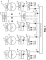
- FIG. 1 illustrates an example of an N-channel direct current (DC) power distribution system (PDS) 10 for sharing power requirements of different types of aircraft electrical system loads.
- the N-channel DC power distribution system includes a plurality of variable frequency generators 14, labeled, #1 through #N, coupled to respective engine driven gearbox pads 12, labeled, #1 through #N, where N is an integer greater than one.
- the gearbox pad 12 can be mounted on a high pressure spool, a low pressure spool or on an auxiliary power unit (APU) of the aircraft.
- An aircraft can include a high pressure spool and a low pressure spool for each engine turbine (e.g., left and right) of the aircraft, and an APU that is driven by a turbine at the tail of the aircraft.
- An AC/DC converter 16 also labeled #1 through #N, converts alternating current (AC) voltage from the generator to DC voltage to be provided to a dedicated bus 18, labeled Bus #1 through Bus #N, for each respective generator via a bus line contactor (BLC) switch 17 disposed between the output of the AC/DC converter 16 and its respective dedicated DC bus 18.
- the BLC switch 17 can be closed during normal operation and opened as a result of a fault.
- Each DC dedicated bus 18 drives one or more dedicated loads (Bus #1 to Bus #N loads) of the aircraft.
- Each of the DC dedicated buses 18 are coupled to a DC synchronization bus 20 via respective synchronization bus line (SBL) switches 21, also referred to as bus tie-breaker (BTB) switches, to allow for selective coupling and decoupling of dedicated buses 18 to the synchronization bus 20, thus allowing for DC power sharing of selected dedicated buses 18 and DC power isolation for other dedicated buses 18.
- SBL synchronization bus line
- BTB bus tie-breaker
- the system 10 includes a bus control unit (BCU) 22 that controls the opening and closing of the SBL switches 21, and the selective coupling and decoupling of SBL switches 21 to the synchronization bus 20, and thus allowing for power sharing among selected dedicated buses 18 and power isolation amongst other dedicated buses 18.
- the BCU 22 is coupled to an aircraft vehicle management system (VMS) 24, which controls the aircraft and its electrical system.
- VMS aircraft vehicle management system
- the BCU 22 and VMS 24 can communicate with another to provide load sharing commands, fault information and commands and a variety of other information useful for communicating between the two units.
- the BCU 22 can rely on discrete logic-based decisions on generator and bus arrangements, as it performs fault detection, isolation and power distribution in addition to information provided to the BCU 22 by the VMS 24 on the aircrafts operating parameters.
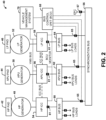
- FIG. 2 illustrates a 3-channel DC PDS 40 for sharing power requirements of different types of aircraft electrical systems (electrical loads).
- the 3-channel DC PDS 40 comprises three DC power channels that are arranged in parallel with respect to one another.
- a first DC power channel comprises a high pressure (HP) generator 48 configured to generate HP alternating current (AC) power and is coupled to a HP Pad 42 (e.g., a gearbox).
- HP Pad 42 is configured to convert mechanical energy (ME) generated by a HP spool of an aircraft engine to electrical energy from which the HP generator 48 utilizes to generate HP-AC power.
- HP high pressure
- ME mechanical energy
- the HP generator 48 is further coupled to an HP-inverter-Converter-Controller (ICC) 54 that is configured to convert the HP-AC power to HP-DC power, and supply the HP-DC power to a dedicated HP Bus 60 for distribution to HP-DC electrical bus loads.
- the 3-channel PDS further comprises a second DC power channel that includes a low pressure (LP) generator 52 coupled to an LP Pad 46 (similar in function as the HP Pad 42), and is configured to supply LP-AC power to an LP-ICC 58, which is configured to convert the LP-AC power to LP-DC power and supply the LP-DC power to a dedicated LP Bus 64 for distribution to the LP-DC electrical bus loads.
- LP low pressure
- the 3-channel PDS 40 further comprises a third DC power channel that includes an auxiliary generator (e.g., an auxiliary power unit (APU)) coupled to APU Pad 44 (similar in function as HP Pad 42 and LP Pad 46), and is configured to supply APU-AC power to an APU-ICC 56, which is configured to convert the APU-AC power to APU-DC power and supply the APU-DC power to dedicated APU Bus 62 for distribution to APU electrical bus loads.
- HP Bus 60, APU Bus 62, and LP Bus 64, respectively, of each DC power channel of the 3-channel PDS are coupled to a respective SBL switches 65 that allows coupling and decoupling between respective dedicated HP Bus 60, APU Bus 62, and LP Bus 64 with a synchronization bus 66.
- the synchronization bus 66 is coupled to an external power contactor (EPC) 67, which enables power to be provided to on board aircraft systems. However, no aircraft loads are connected directly to the synchronization bus 66.
- EPC external power contactor
- Each ICC 54, 56 and 58 has a bus line contactor (BLC) switch 61 at which its input is the point of regulation (POR) for the generating system and to which its output is connected a respective dedicated DC bus.
- BLC bus line contactor
- the 3-channel PDS further comprises a BCU 68 housing executable instructions that control each DC power channel of the 3-channel PDS 40 in cooperation with a VMS 70 in an intelligent manner based on changes (variations) in aircraft operating parameters (e.g., changes in fuel quantity, engine performance, altitude, airspeed, etc). For example, during normal flight operations (e.g., when the aircraft operating parameters are non-varying), the BCU 68 in cooperation with the VMS 70 can maintain each SBL switch 65 of each DC power channel in an open condition. Since each SBL 65 of each DC power channel is open, each DC power channel satisfies the power requirements of the electrical loads that are coupled at their respective dedicated bus.
- aircraft operating parameters e.g., changes in fuel quantity, engine performance, altitude, airspeed, etc.
- the BCU 68 in cooperation with the VMS 70 can be configured to control the HP-ICC 54, the LP-ICC 58, the APU-ICC 56, and each SBL 65 (e.g., by changing the SBL to a closed condition), as illustrated in FIG. 2 with dashed lines, so that power requirements of electrical loads that are coupled to each bus is dynamically shared (distributed) amongst one or more of the HP, APU and LP generators 48, 50 and 52, respectively.
- Dynamically sharing the power requirements of the electrical loads coupled to a respective DC power channel with other DC power channels reduces an amount of horsepower required to be extracted by a respective generator (e.g., HP generator) to satisfy the power requirements of the electrical loads.
- the systems and methods can operate multiple 270Vdc generating systems in parallel with one another in a robust and stable manner. This can be achieved through the use of both voltage and current feedback loops to continuously update the voltage regulation at the respective POR of each generating system such that no single generating system overrides another. Voltage regulation of each generating system operating in parallel is such that as a combined system, it can conform to Mil-Std-704F power quality utilizing a delta-voltage between generating systems of less than 5.0Vdc.
- the three channels can be operated stand-alone as three separate generators feeding regulated 270Vdc power to their respective dedicated buses.
- any two, or all, of the SBLs are closed thereby forcing two or more of the DC generating systems in parallel with one another.
- the generating systems therefore now share the aircraft loads that are connected to the individual dedicated buses through the closed SBLs 65 via the synchronization Bus 66.
- the amount of the total aircraft electrical load that each generating system is set to supply can be set by a ratio asserted by the VMS 70.
- This ratio can be determined through contemplating numerous aircraft operating parameters and can be continuously updated while any two or more channels are operating in parallel in effort to maximize overall aircraft operating efficiency and performance.
- Example aircraft operating parameters may include generator maximum power output ratings, total aircraft electrical load, air speed, altitude, fuel quantity, engine performance and thermal management system performance.
- continuously adjusting the sharing ratio allows for the dynamic shifting of horsepower extraction between HP and LP spools of the same, or a separate, engine as well as an APU, as aircraft and engine performance conditions dictate.
- More immediate local control of the system in terms of its configuration through the open and closure of the SBLs and EPC, is accomplished by the BCU as it contemplates discrete inputs from the ICCs and the aircraft. Examples of BCU inputs are ICC over-current, ICC stop-parallel, ICC fault, SBL status, bus over-current and external power monitoring. Through discrete logic, the BCU can rapidly reconfigure the PDS as faults occur and clear within the system.
- the BCU can rely on discrete logic-based decisions on generator and bus arrangement, or grid configuration, as it performs fault detection, isolation and coordination. Should a source go off-line, or should a fault occur in the distribution system, the BCU, with discrete inputs from the aircraft and the ICCs, commands the SBLs open or closed within 5.0ms of the event. In the event of a bus over-current, the BCU logic will operate faster, opening the SBLs isolating the fault, than that of the ICC protective functions as to prevent that downstream fault from taking viable sources off-line. In conventional stand alone mode, should a source trip off, the BCU will close SBLs allowing the remaining sources to parallel and share the load that had been supplied by the now-off-line generator.
- a load share command can be issued by the VMS to provide a share ratio command to the generating systems to govern the amount of power each is supplying to the total load demanded by the vehicle.
- this command is expressed in a percentage similar to 20%: 35%: 45%, HP: LP: APU.
- the percentage of the aircraft total load that any one generator can supply based on a number of VMS-determined aircraft operating parameters including generator maximum power output ratings, total aircraft electrical load, air speed, altitude, fuel quantity, engine performance and thermal management system performance.
- the ICC 2 can have a set of default load share ratios programmed into the ICCs such that as the BCU informs the ICCs of the requirement to reconfigure the system, the ICCs can immediately revert to a given set of ratios.
- these default ratios are set based on each generating systems' maximum continuous output ratings, for example, 13%: 43.5%: 43.5%.
- advanced energy storage is provided. It can be employed in both high voltage battery (270V nominal) and low voltage battery (28V nominal) applications, each contributing to the overall efficiency of the electrical system and the aircraft.
- the 270V battery is floated on the 270Vdc bus allowing it to immediately fill-in when large on-load transients are applied to the bus as well as absorb energy when large off-load transients or regenerative energy events occur in the system. This allows the generating system to not be over-sized to handle these excursions as well as mitigates horsepower extraction transients on the engine and the engine gearbox.
- the 28V batteries can be employed in a similar floating fashion, but are physically distributed throughout the aircraft in effort to both minimize voltage drop to the flight-critical loads as well as allow for better response in transient suppression.
- Distribution of electrical power in the systems and methods can be performed by both conventional electro-mechanical switch devices and by solid-sate switch devices.
- the BLC switches and the SBL switches can be electro-mechanical switches, while the individual load switches can be solid-state devices.
- the solid-state devices provide faster switch times than conventional contactors and are programmed with trip curves and inrush limiting curves such that both normal and abnormal operation of the various aircraft loads can be managed in a timely manner.
- Fault detection and isolation begins with solid-state load switches and is coordinated with the BCU and ICC protective functions such that a fault with a load is managed accordingly.
- Integrating high-power batteries into an electrical system brings with it the need to safely connect and disconnect to and from a bus. If a fault occurs when a battery is sourcing a bus, or when a battery is applied to an already-faulted bus, a method of interrupting that fault current is required in effort to preserve the hardware.
- the systems and methods can employ an advanced contactor that is designed to make and break battery-sourced fault currents in excess of 8,000 amps.
- Carbon nano-tube cables have been identified as showing up to approximately 40% in cable weight savings, especially when used in shielding of twisted-pair communication lines.
- carbon nano-tube signal cables have an improved cable and harness flexibility, improved bend radii and improved thermal performance.
- FIG. 3 An example methodology will be better appreciated with reference to FIG. 3 . While, for purposes of simplicity of explanation, the methodology of FIG. 3 is shown and described as executing serially, it is to be understood and appreciated that the present invention is not limited by the illustrated order, as some actions could in other examples occur in different orders and/or concurrently from that shown and described herein.
- FIG. 3 illustrates a flow diagram of a method for distributing DC power in an aircraft employing a synchronization bus selectively coupleable to dedicated DC buses by respective synchronization bus line switches.
- the methodology begins at 100 where a plurality of AC voltages are generated from a plurality of sources.
- the plurality of sources could be generators associated with one or more HP and/or LP spools driven by one or more engine turbines. Additionally, the plurality of sources could be an APU driven by an engine turbine at a tail of the aircraft.
- the methodology then proceeds to 120, where the plurality of AC voltages are converted to a plurality of DC voltages, for example, by a plurality of AC/ DC converters.
- each DC voltage is provided to a respective dedicated DC bus that is coupled to respective dedicated bus loads.
- the methodology then advances to 140.
- one or more operating parameters are measured associated with the PDS of the aircraft and/or the operation of the aircraft.
- the methodology then proceeds to 150.
Landscapes
- Engineering & Computer Science (AREA)
- Power Engineering (AREA)
- Aviation & Aerospace Engineering (AREA)
- Supply And Distribution Of Alternating Current (AREA)
Description
- This disclosure relates generally to power systems, and more particularly to aircraft DC power distribution systems and methods.
- Efficiency, for an electrical system, can refer not only to minimizing losses in individual system components, but can also entail minimizing the amount of hardware in the system as well as optimizing the manner in which power is generated, converted and distributed by that electrical system. This is especially true for aircraft which needs to rely on a limited number of power generating sources and distribution components it can reasonably carry on board for providing electrical power.
- Generators on aircraft may be driven with various prime movers, such as turbine engines. In many cases, a prime mover may drive a generator only as an ancillary function. A typical primary function for a prime mover, such as a turbine engine, may be to provide propulsion thrust for the aircraft. In the context of its primary function, the prime mover may operate at varying rotational speeds. Therefore, a generator coupled to a shaft of such a variable-speed prime mover may rotate at varying speeds. Additionally, a generator load may become large enough to negatively affect engine thrust output. Because of recent increases in electrical power demand of aircraft, a single generator driven by a single prime mover may not be capable of producing all of the electrical power for an aircraft. Consequently, an aircraft may be provided with multiple generators, each driven by different prime movers.
- Certain aircraft operating conditions may arise in which a particular generator may be subjected to a particularly high load demand during a time when its associated prime mover may be performing its primary function (e.g. producing thrust) at a relatively low speed. In order to meet the high electrical power requirement of an attached generator, it may be necessary to increase the speed of the prime mover, even though such an increase in speed may not otherwise be required for the primary function of the prime mover. Excessive fuel may be consumed if and when a prime mover is operated at a speed greater than required for its primary role. Certain design efforts have been directed to this issue. For example multiple generators may be driven on different shafts of a turbine machine. The turbine machine may have a low-pressure turbine output shaft and a high-pressure turbine output shaft. A separate generator may be driven by each of the shafts. Electrical outputs of the generators may be shared and controlled so that electrical loads may be allocated to either the low-pressure turbine or the high-pressure turbine as a function of turbine operating speed. This allocation may facilitate more efficient operation of the turbine machine.
- Historically, multiple generators and distribution channels are employed within an aircraft such that a fault in any one system will not either jeopardize safe operation of the aircraft or compromise the aircraft's ability to complete its mission. While this has proven to be a robust approach, it does create a redundancy that reduces the overall efficiency of the electrical system itself, as well as the efficiency of other aircraft systems with which it interfaces such as propulsion and thermal management systems.
-
US 2015/123463 A1 discloses an electrical power system for an aircraft having electrical loads and at least one jet engine with a high pressure spool and a low pressure spool, the electrical power system includes a first electrical machine (generator) driven by a first pressure spool and outputting a first voltage, a second electrical machine (generator) driven by a second pressure spool and outputting a second voltage, and an electrical distribution bus receiving the first and second voltages and supplying the voltages to the loads. -
US 4 403 292 A discloses a control for an electrical generating and distribution system comprising serial data links between a bus power control unit and each of generator control units, which provide for communication of input and control information and enable comparison of redundant circuit information enhancing reliability of the system operation. - In one example, an aircraft power system is provide that comprises a plurality of generators that generate respective AC voltage signals in response to mechanical energy generated by one or more aircraft turbines, a plurality of AC/DC converters that each receive a respective AC output signal from a respective generator and generate a respective DC voltage, and a plurality of dedicated DC buses, wherein each dedicated DC bus is associated with a respective generator and a respective AC/DC converter to receive a respective DC voltage. Each dedicated bus provides power to one or more associated dedicated bus loads. A synchronization bus is selectively coupleable to each dedicated DC bus by respective synchronization bus line switches to allow for bus sharing between a first set of dedicated DC buses of the plurality of dedicated DC buses and bus isolation of a second set of selected dedicated DC buses of the plurality of dedicated DC buses.
- In another example, an aircraft power system is provided that comprises a first generator that generates a first AC voltage signal from a high pressure spool, a second generator that generates a second AC voltage signal from a low pressure spool, a first AC/ DC converter that converts the first AC voltage signal to a first DC voltage, and a second AC/ DC converter that converts the second AC voltage signal to a second DC voltage signal. The aircraft power system further comprises a first dedicated DC bus that receives the first DC voltage and provides the first DC voltage to one or more first dedicated bus loads, a second dedicated DC bus that receives the second DC voltage and provides the second DC voltage to one or more second dedicated bus loads, and a synchronization bus selectively coupleable to the first dedicated bus by a first bus line switch and the second dedicated bus by a second bus line switch to allow for selective bus sharing between the first and second dedicated buses, wherein there are not any bus loads that are directly coupled to the synchronization bus. A bus controller controls the selective closing and opening of the synchronization bus line switches.
- In another example, a method for distributing DC power in an aircraft is provided that includes generating a plurality of DC voltages from a plurality of independent sources driven by one or more turbines of the aircraft, providing each of the plurality of DC voltages to respective dedicated DC buses, and setting a plurality of switches that selectively couples a first set of dedicated DC buses to a synchronization bus to allow for bus sharing between the first set of dedicated DC buses and bus isolation of a second set of dedicated DC buses.
-
-
FIG. 1 illustrates an example of an N-channel direct current (DC) power distribution system (PDS) for sharing power requirements of different types of aircraft electrical system loads. -
FIG. 2 illustrates a 3-channel DC PDS for sharing power requirements of different types of aircraft electrical systems (electrical loads). -
FIG. 3 illustrates a flow diagram of a method for distributing DC power in an aircraft. - Direct current (DC) power distribution systems and methods are provided for aircraft that leverage multiple power generating sources driven by multiple engine spools and can employ aircraft-level advanced control algorithms governing aircraft-quality advanced components. This electrical power distribution technique for an aircraft, through intelligent control of advanced components, affords an aircraft the ability to provide, for a given weight and volume, greater power generation capability and a more fault-tolerant distribution system. The electrical power distribution systems and methods can take advantage of low-pressure spool horsepower extraction since, for a given specific fuel consumption, it is more efficient than extracting horsepower from the high-pressure spool of the engine. The electrical power distribution techniques combine and dynamically control DC power sharing from each generator in an intelligent manner based on different states of the aircraft and the turbines driving the generators through selectively coupling and decoupling of DC power from dedicated busses to and from a separate synchnronization bus.
-
FIG. 1 illustrates an example of an N-channel direct current (DC) power distribution system (PDS) 10 for sharing power requirements of different types of aircraft electrical system loads. The N-channel DC power distribution system includes a plurality ofvariable frequency generators 14, labeled, #1 through #N, coupled to respective engine drivengearbox pads 12, labeled, #1 through #N, where N is an integer greater than one. Thegearbox pad 12 can be mounted on a high pressure spool, a low pressure spool or on an auxiliary power unit (APU) of the aircraft. An aircraft can include a high pressure spool and a low pressure spool for each engine turbine (e.g., left and right) of the aircraft, and an APU that is driven by a turbine at the tail of the aircraft. - An AC/
DC converter 16, also labeled #1 through #N, converts alternating current (AC) voltage from the generator to DC voltage to be provided to adedicated bus 18, labeledBus # 1 through Bus #N, for each respective generator via a bus line contactor (BLC)switch 17 disposed between the output of the AC/DC converter 16 and its respectivededicated DC bus 18. TheBLC switch 17 can be closed during normal operation and opened as a result of a fault. Each DC dedicatedbus 18 drives one or more dedicated loads (Bus # 1 to Bus #N loads) of the aircraft. Each of the DCdedicated buses 18 are coupled to aDC synchronization bus 20 via respective synchronization bus line (SBL)switches 21, also referred to as bus tie-breaker (BTB) switches, to allow for selective coupling and decoupling ofdedicated buses 18 to thesynchronization bus 20, thus allowing for DC power sharing of selecteddedicated buses 18 and DC power isolation for otherdedicated buses 18. - The
system 10 includes a bus control unit (BCU) 22 that controls the opening and closing of theSBL switches 21, and the selective coupling and decoupling of SBL switches 21 to thesynchronization bus 20, and thus allowing for power sharing among selecteddedicated buses 18 and power isolation amongst otherdedicated buses 18. The BCU 22 is coupled to an aircraft vehicle management system (VMS) 24, which controls the aircraft and its electrical system. The BCU 22 and VMS 24 can communicate with another to provide load sharing commands, fault information and commands and a variety of other information useful for communicating between the two units. In one example, the BCU 22 can rely on discrete logic-based decisions on generator and bus arrangements, as it performs fault detection, isolation and power distribution in addition to information provided to theBCU 22 by the VMS 24 on the aircrafts operating parameters. -
FIG. 2 illustrates a 3-channel DC PDS 40 for sharing power requirements of different types of aircraft electrical systems (electrical loads). The 3-channel DC PDS 40 comprises three DC power channels that are arranged in parallel with respect to one another. A first DC power channel comprises a high pressure (HP)generator 48 configured to generate HP alternating current (AC) power and is coupled to a HP Pad 42 (e.g., a gearbox). HP Pad 42 is configured to convert mechanical energy (ME) generated by a HP spool of an aircraft engine to electrical energy from which the HPgenerator 48 utilizes to generate HP-AC power. The HPgenerator 48 is further coupled to an HP-inverter-Converter-Controller (ICC) 54 that is configured to convert the HP-AC power to HP-DC power, and supply the HP-DC power to a dedicated HPBus 60 for distribution to HP-DC electrical bus loads. The 3-channel PDS further comprises a second DC power channel that includes a low pressure (LP)generator 52 coupled to an LP Pad 46 (similar in function as the HP Pad 42), and is configured to supply LP-AC power to an LP-ICC 58, which is configured to convert the LP-AC power to LP-DC power and supply the LP-DC power to adedicated LP Bus 64 for distribution to the LP-DC electrical bus loads. - The 3-
channel PDS 40 further comprises a third DC power channel that includes an auxiliary generator (e.g., an auxiliary power unit (APU)) coupled to APU Pad 44 (similar in function as HP Pad 42 and LP Pad 46), and is configured to supply APU-AC power to an APU-ICC 56, which is configured to convert the APU-AC power to APU-DC power and supply the APU-DC power to dedicated APUBus 62 for distribution to APU electrical bus loads. HP Bus 60, APU Bus 62, andLP Bus 64, respectively, of each DC power channel of the 3-channel PDS are coupled to arespective SBL switches 65 that allows coupling and decoupling between respective dedicated HP Bus 60, APU Bus 62, andLP Bus 64 with asynchronization bus 66. Thesynchronization bus 66 is coupled to an external power contactor (EPC) 67, which enables power to be provided to on board aircraft systems. However, no aircraft loads are connected directly to thesynchronization bus 66. EachICC - The 3-channel PDS further comprises a
BCU 68 housing executable instructions that control each DC power channel of the 3-channel PDS 40 in cooperation with aVMS 70 in an intelligent manner based on changes (variations) in aircraft operating parameters (e.g., changes in fuel quantity, engine performance, altitude, airspeed, etc). For example, during normal flight operations (e.g., when the aircraft operating parameters are non-varying), theBCU 68 in cooperation with theVMS 70 can maintain each SBL switch 65 of each DC power channel in an open condition. Since eachSBL 65 of each DC power channel is open, each DC power channel satisfies the power requirements of the electrical loads that are coupled at their respective dedicated bus. - However, when the aircraft starts deviating from normal flight operations, for example during an altitude change, the
BCU 68 in cooperation with theVMS 70 can be configured to control the HP-ICC 54, the LP-ICC 58, the APU-ICC 56, and each SBL 65 (e.g., by changing the SBL to a closed condition), as illustrated inFIG. 2 with dashed lines, so that power requirements of electrical loads that are coupled to each bus is dynamically shared (distributed) amongst one or more of the HP, APU andLP generators - In one example, the systems and methods can operate multiple 270Vdc generating systems in parallel with one another in a robust and stable manner. This can be achieved through the use of both voltage and current feedback loops to continuously update the voltage regulation at the respective POR of each generating system such that no single generating system overrides another. Voltage regulation of each generating system operating in parallel is such that as a combined system, it can conform to Mil-Std-704F power quality utilizing a delta-voltage between generating systems of less than 5.0Vdc.
- Similar to a conventional electrical system, during normal operation with all three SBLs open, the three channels can be operated stand-alone as three separate generators feeding regulated 270Vdc power to their respective dedicated buses. Dynamically, in response to a change in conditions, any two, or all, of the SBLs are closed thereby forcing two or more of the DC generating systems in parallel with one another. The generating systems therefore now share the aircraft loads that are connected to the individual dedicated buses through the
closed SBLs 65 via thesynchronization Bus 66. The amount of the total aircraft electrical load that each generating system is set to supply can be set by a ratio asserted by theVMS 70. This ratio can be determined through contemplating numerous aircraft operating parameters and can be continuously updated while any two or more channels are operating in parallel in effort to maximize overall aircraft operating efficiency and performance. Example aircraft operating parameters may include generator maximum power output ratings, total aircraft electrical load, air speed, altitude, fuel quantity, engine performance and thermal management system performance. - Taking engine performance for example, continuously adjusting the sharing ratio allows for the dynamic shifting of horsepower extraction between HP and LP spools of the same, or a separate, engine as well as an APU, as aircraft and engine performance conditions dictate. More immediate local control of the system, in terms of its configuration through the open and closure of the SBLs and EPC, is accomplished by the BCU as it contemplates discrete inputs from the ICCs and the aircraft. Examples of BCU inputs are ICC over-current, ICC stop-parallel, ICC fault, SBL status, bus over-current and external power monitoring. Through discrete logic, the BCU can rapidly reconfigure the PDS as faults occur and clear within the system.
- In one example, the BCU can rely on discrete logic-based decisions on generator and bus arrangement, or grid configuration, as it performs fault detection, isolation and coordination. Should a source go off-line, or should a fault occur in the distribution system, the BCU, with discrete inputs from the aircraft and the ICCs, commands the SBLs open or closed within 5.0ms of the event. In the event of a bus over-current, the BCU logic will operate faster, opening the SBLs isolating the fault, than that of the ICC protective functions as to prevent that downstream fault from taking viable sources off-line. In conventional stand alone mode, should a source trip off, the BCU will close SBLs allowing the remaining sources to parallel and share the load that had been supplied by the now-off-line generator.
- In another example, a load share command can be issued by the VMS to provide a share ratio command to the generating systems to govern the amount of power each is supplying to the total load demanded by the vehicle. In the three-channel system, for example, this command is expressed in a percentage similar to 20%: 35%: 45%, HP: LP: APU. The percentage of the aircraft total load that any one generator can supply based on a number of VMS-determined aircraft operating parameters including generator maximum power output ratings, total aircraft electrical load, air speed, altitude, fuel quantity, engine performance and thermal management system performance. As built, the 3-channel PDS in
FIG. 2 can have a set of default load share ratios programmed into the ICCs such that as the BCU informs the ICCs of the requirement to reconfigure the system, the ICCs can immediately revert to a given set of ratios. In this case, these default ratios are set based on each generating systems' maximum continuous output ratings, for example, 13%: 43.5%: 43.5%. - In another example, advanced energy storage is provided. It can be employed in both high voltage battery (270V nominal) and low voltage battery (28V nominal) applications, each contributing to the overall efficiency of the electrical system and the aircraft. The 270V battery is floated on the 270Vdc bus allowing it to immediately fill-in when large on-load transients are applied to the bus as well as absorb energy when large off-load transients or regenerative energy events occur in the system. This allows the generating system to not be over-sized to handle these excursions as well as mitigates horsepower extraction transients on the engine and the engine gearbox. The 28V batteries can be employed in a similar floating fashion, but are physically distributed throughout the aircraft in effort to both minimize voltage drop to the flight-critical loads as well as allow for better response in transient suppression.
- Distribution of electrical power in the systems and methods can be performed by both conventional electro-mechanical switch devices and by solid-sate switch devices. The BLC switches and the SBL switches can be electro-mechanical switches, while the individual load switches can be solid-state devices. The solid-state devices provide faster switch times than conventional contactors and are programmed with trip curves and inrush limiting curves such that both normal and abnormal operation of the various aircraft loads can be managed in a timely manner. Fault detection and isolation begins with solid-state load switches and is coordinated with the BCU and ICC protective functions such that a fault with a load is managed accordingly.
- Integrating high-power batteries into an electrical system brings with it the need to safely connect and disconnect to and from a bus. If a fault occurs when a battery is sourcing a bus, or when a battery is applied to an already-faulted bus, a method of interrupting that fault current is required in effort to preserve the hardware. The systems and methods can employ an advanced contactor that is designed to make and break battery-sourced fault currents in excess of 8,000 amps.
- The systems and methods can make use of carbon nano-tube cables as another method of improving overall efficiency. Carbon nano-tube cables have been identified as showing up to approximately 40% in cable weight savings, especially when used in shielding of twisted-pair communication lines. In addition, carbon nano-tube signal cables have an improved cable and harness flexibility, improved bend radii and improved thermal performance.
- In view of the foregoing structural and functional features described above, an example methodology will be better appreciated with reference to
FIG. 3 . While, for purposes of simplicity of explanation, the methodology ofFIG. 3 is shown and described as executing serially, it is to be understood and appreciated that the present invention is not limited by the illustrated order, as some actions could in other examples occur in different orders and/or concurrently from that shown and described herein. -
FIG. 3 illustrates a flow diagram of a method for distributing DC power in an aircraft employing a synchronization bus selectively coupleable to dedicated DC buses by respective synchronization bus line switches. The methodology begins at 100 where a plurality of AC voltages are generated from a plurality of sources. The plurality of sources could be generators associated with one or more HP and/or LP spools driven by one or more engine turbines. Additionally, the plurality of sources could be an APU driven by an engine turbine at a tail of the aircraft. The methodology then proceeds to 120, where the plurality of AC voltages are converted to a plurality of DC voltages, for example, by a plurality of AC/ DC converters. At 130, each DC voltage is provided to a respective dedicated DC bus that is coupled to respective dedicated bus loads. The methodology then advances to 140. - At 140, one or more operating parameters are measured associated with the PDS of the aircraft and/or the operation of the aircraft. The methodology then proceeds to 150. At 150, it is determined whether or not the optimal settings for bus sharing and/ or bus isolation has been selected based on the one or more operating parameters. That is whether certain buses should be coupled to the one another through the synchronization bus, and whether certain buses should be isolated from the synchronization bus based on the measured operating parameters. If the optimal setting has not been achieved (NO), the methodology proceeds to 160 to set the synchronization bus line switches for selective bus sharing and/or selective bus isolation based on the measured parameters. If the optimal setting has been achieved (YES), the methodology returns to 130 to repeat the providing of DC voltages to dedicated bus, the measuring of one or more parameters at 140, and the determining of optimal setting at 150.
- What have been described above are examples. It is, of course, not possible to describe every conceivable combination of structures, components, or methods, but one of ordinary skill in the art will recognize that many further combinations and permutations are possible. Where the disclosure or claims recite "a," "an," "a first," or "another" element, or the equivalent thereof, it should be interpreted to include one or more than one such element, neither requiring nor excluding two or more such elements. As used herein, the term "includes" means includes but not limited to, and the term "including" means including but not limited to. The term "based on" means based at least in part on.
Claims (14)
- An aircraft power distribution system (10) comprising:a plurality of generators (14) that generate respective AC voltage signals in response to mechanical energy generated by one or more aircraft turbines of an aircraft;a plurality of inverter-converter-controllers (54, 56, 58), each of the plurality of inverter-converter-controllers (54, 56, 58) including an AC/DC converters (16) that receives a respective AC output signal from a respective generator (14) and generate a respective DC voltage to provide a given amount of power;a plurality of dedicated DC buses (18), wherein each dedicated DC bus (18) is associated with a respective generator (14) and a respective AC/DC converter (16) and to receive a respective DC voltage, each dedicated bus providing the given amount of power to one or more associated dedicated bus loads;a synchronization bus (20) selectively coupleable to each dedicated DC bus (18) by respective synchronization bus line switches (21) to allow for bus sharing between a first set of dedicated DC buses of the plurality of dedicated DC buses and isolating a second set of selected dedicated DC buses of the plurality of dedicated DC buses a bus;a controller (22) that controls selective closing and opening of the respective synchronization bus line switches (21) and controls the given amount of power that the respective AC/DC converter (16) provides when the respective synchronization bus line switch (21) is in one of a closed state and open state based on a value determined based on aircraft operating parameters of the aircraft; andcharacterized in that the aircraft power system (10) further comprises a vehicle management system (24) to issue a load share command, to the plurality of inverter-converter-controllers (54, 56, 58), that governs a percentage of power that is supplied by each of the plurality of inverter-converter-controllers (54, 56, 58),wherein load share default ratios are programmed into each of the plurality of inverter-converter-controllers (54, 56, 58) based on maximum continuous output ratings of each generating system comprised of one of the plurality of generators (14), one of the plurality of inverter-converter-controllers (54, 56, 58), and one of the plurality of dedicated DC buses (18), andwherein the vehicle management system (24) issues a command to revert the plurality of inverter-converter-controllers (54, 56, 58) to load share default ratios to reconfigure the aircraft power distribution system (10).
- The system (10) of claim 1, further comprising a bus controller that controls the selective closing and opening of the synchronization bus line switches, wherein the bus controller is communicatively coupled to the vehicle management system of the aircraft to receive commands, the value and/ or share status information on the state of the power distribution system (10) and/ or the aircraft.
- The system (10) of claim 2, wherein the bus controller receives discrete input feedback from the power distribution system in determining the state of the synchronization bus line switches.
- The system (10) of claim 1, wherein at least one of the generators is associated with a high pressure spool of the aircraft, and at least one of the generators is associated with a low pressure spool of the aircraft.
- The system (10) of claim 1, wherein each of the plurality of inverter-converter-controllers (54, 56, 58) includes a bus line contactor switch that couples and decouples the respective AC/ DC converter from its respective dedicated bus.
- The system (10) of claim 1, wherein the plurality of generators comprises a first generator associated with a first high pressure spool coupled to a first engine of the aircraft and a second generator associated with a first low pressure spool coupled to the first engine of the aircraft, and a third generator associated with a second high pressure spool coupled to a second engine of the aircraft and a fourth generator associated with a second low pressure spool coupled to the second engine of the aircraft.
- An aircraft power distribution system (10) of claim 1, wherein
the plurality of generators comprises:a first generator that generates a first AC voltage signal from a high pressure spool;a second generator that generates a second AC voltage signal from a low pressure spool,the plurality of inverter-converter-controllers (54, 56, 58) comprises:a first inverter-converter-controllers (54) that converts the first AC voltage signal to a first DC voltage to provide a respective amount of power; anda second inverter-converter-controllers (56) that converts the second AC voltage signal to a second DC voltage signal to provide a respective amount of power,the plurality of dedicated DC buses comprisesa first dedicated DC bus that receives the first DC voltage and provides the first DC voltage to one or more first dedicated bus loads; anda second dedicated DC bus that receives the second DC voltage and provides the second DC voltage to one or more second dedicated bus loads,the synchronization bus selectively coupleable to the first dedicated DC bus by a first bus line switch and the second dedicated DC bus by a second bus line switch to allow for selective bus sharing between the first and second dedicated DC buses, wherein there are not any bus loads that are directly coupled to the synchronization bus,the controller that controls the selective closing and opening of the synchronization bus line switches and controls the respective amount of power that each of the first and the second AC/DC converters provide when respective synchronization bus lines switches are in one of a respective closed state and open state based on a value determined based on aircraft operating parameters of an aircraft; andthe vehicle management system to issue a load share command, to the first and second AC/DC converters, that governs a percentage of power that is supplied by each of the first and second AC/DC converterswherein the vehicle management system issues a command to revert the first inverter-converter-controller (54) and the second inverter-converter-controller (56) to load share default ratios ratios to reconfigure the aircraft power distribution system. - The system (10) of claim 7, wherein the controller is communicatively coupled to a vehicle management system of the aircraft to receive commands, the value and/ or share status information on the state of the power distribution system and/ or the aircraft.
- The system (10) of claim 7, further comprising:a third generator that generates a third AC voltage signal from an auxiliary power unit;a third inverter-converter-controller (58) comprising a third AC/ DC converter that converts the third AC voltage signal to a third DC voltage;a third dedicated DC bus that receives the third DC voltage and provides the third DC voltage to one or more third dedicated bus loads, wherein the synchronization bus is selectively coupleable to the third dedicated DC bus by a third bus line switch to allow for selective bus sharing and bus isolation between the first, second and third dedicated DC buses via the bus controller.
- The system (10) of claim 8, wherein the first inverter-converter-controller (54) and the second inverter-converter-controller (56) communicates with the bus controller to share status information of the power distribution system (10) and wherein the first inverter-converter-controller (54) and the second inverter-converter-controller (56) includes a bus line contactor switch that couples and decouples the respective AC/ DC converter from its respective dedicated DC bus.
- The system (10) of claim 7, further comprising:a third generator that generates a third AC voltage signal from a second high pressure spool;a fourth generator that generates a fourth AC voltage signal from a second low pressure spool;a third inverter-converter-controller (58) comprising a third AC/ DC converter that converts the third AC voltage signal to a third DC voltage;a fourth inverter-converter-controller comprising a fourth AC/ DC converter that converts the fourth AC voltage signal to a fourth DC voltage signal;a third dedicated DC bus that receives the third DC voltage and provides the third DC voltage to one or more third dedicated bus loads;a fourth dedicated DC bus that receives the fourth DC voltage and provides the fourth DC voltage to one or more fourth dedicated bus loads, wherein the synchronization bus is selectively coupleable to the third dedicated bus by a third bus line switch and the fourth dedicated bus by a fourth bus line switch to allow for selective bus sharing between the first, second, third and fourth dedicated buses.
- A method of distributing DC power in an aircraft, the method comprising;generating, with a plurality of inverter-converter-controllers, each of the plurality of inverter-converter-controllers comprising an AC/DC converters associated with the aircraft, a plurality of DC voltages having a given amount of power from a plurality of independent sources driven by one or more turbines of the aircraft;providing each of the plurality of DC voltages to respective dedicated DC buses;setting a plurality of switches that selectively couples a first set of dedicated DC buses to a synchronization bus to allow for bus sharing between the first set of dedicated DC buses and isolating a second set of dedicated buses;setting the given amount of power that a respective independent source provides when a respective switch is in one of a closed state and open state based on a value determined based on aircraft operating parameters of the aircraft; andissuing a load share command, to the plurality of inverter-converter-controllers (54, 56, 58), that governs a percentage of power that is supplied by each of the plurality of AC/DC converters; andissuing a command, by a vehicle management system, to revert plurality of inverter-converter-controllers (54, 56, 58) to load share default ratios to reconfigure the aircraft power distribution system (10),wherein the load share default ratios are programmed into each of the plurality of inverter-converter-controllers (54, 56, 58) based on maximum continuous output ratings of each generating system comprised of one of the plurality of generators (14), one of the plurality of inverter-converter-controllers (54, 56, 58), and one of the plurality of dedicated DC buses (18).
- The method of claim 12, further comprising monitoring one or more parameters of the aircraft and dynamically setting the plurality of switches based on changes in the monitored one or more parameters.
- The method of claim 12, wherein the independent sources comprise one or more high pressure spools, one or more low pressure spools and an auxiliary power unit.
Applications Claiming Priority (2)
| Application Number | Priority Date | Filing Date | Title |
|---|---|---|---|
| US14/729,925 US10090676B2 (en) | 2015-06-03 | 2015-06-03 | Aircraft DC power distribution systems and methods |
| PCT/US2016/031748 WO2016195936A1 (en) | 2015-06-03 | 2016-05-11 | Aircraft dc power distribution systems and methods |
Publications (2)
| Publication Number | Publication Date |
|---|---|
| EP3304674A1 EP3304674A1 (en) | 2018-04-11 |
| EP3304674B1 true EP3304674B1 (en) | 2024-12-18 |
Family
ID=56072442
Family Applications (1)
| Application Number | Title | Priority Date | Filing Date |
|---|---|---|---|
| EP16724795.6A Active EP3304674B1 (en) | 2015-06-03 | 2016-05-11 | Aircraft dc power distribution systems and methods |
Country Status (3)
| Country | Link |
|---|---|
| US (1) | US10090676B2 (en) |
| EP (1) | EP3304674B1 (en) |
| WO (1) | WO2016195936A1 (en) |
Families Citing this family (51)
| Publication number | Priority date | Publication date | Assignee | Title |
|---|---|---|---|---|
| US10243366B2 (en) * | 2015-08-07 | 2019-03-26 | Ge Energy Products France Snc | Auxiliary electric energy storage and supply system for a power plant |
| US10654578B2 (en) | 2016-11-02 | 2020-05-19 | Rolls-Royce North American Technologies, Inc. | Combined AC and DC turboelectric distributed propulsion system |
| US10934935B2 (en) * | 2017-01-30 | 2021-03-02 | Ge Aviation Systems Llc | Engine core assistance |
| GB2559956B (en) * | 2017-02-15 | 2020-09-16 | Ge Aviat Systems Ltd | Power distribution node for a power architecture |
| US11970062B2 (en) * | 2017-04-05 | 2024-04-30 | Ge Aviation Systems Llc | Systems and methods of power allocation for hybrid electric architecture |
| CA3005542A1 (en) * | 2017-05-23 | 2018-11-23 | Pratt & Whitney Canada Corp. | Engine assembly with a dedicated voltage bus |
| FR3068532A1 (en) * | 2017-06-29 | 2019-01-04 | Zodiac Aero Electric | ELECTRICAL POWER DISTRIBUTION BOX FOR AN AIRCRAFT DRIVING NETWORK AND CORRESPONDING POWER SUPPLY SYSTEM |
| US10640225B2 (en) * | 2017-07-10 | 2020-05-05 | Rolls-Royce North American Technologies, Inc. | Selectively regulating current in distributed propulsion systems |
| US10644630B2 (en) | 2017-11-28 | 2020-05-05 | General Electric Company | Turbomachine with an electric machine assembly and method for operation |
| CN108288853B (en) * | 2018-04-04 | 2024-05-28 | 中国商用飞机有限责任公司北京民用飞机技术研究中心 | Aircraft DC power supply system and power supply method |
| CN108964149A (en) * | 2018-07-26 | 2018-12-07 | 国网辽宁省电力有限公司经济技术研究院 | Consider the alternating current-direct current flexible interconnection power distribution network control method for coordinating of fault condition |
| FR3085667B1 (en) | 2018-09-12 | 2020-11-20 | Safran | SERIES HYBRID PROPULSION KIT FOR AIRCRAFT |
| US11027719B2 (en) * | 2018-12-03 | 2021-06-08 | General Electric Company | Distributed power generation for a vehicle system |
| FR3093870B1 (en) * | 2019-03-15 | 2021-04-02 | Safran Electrical & Power | Aircraft electrical network control system |
| US10868483B1 (en) | 2019-06-03 | 2020-12-15 | Hamilton Sundstrand Corporation | DC generator system |
| US11549464B2 (en) * | 2019-07-25 | 2023-01-10 | Raytheon Technologies Corporation | Hybrid gas turbine engine starting control |
| US11428171B2 (en) | 2019-12-06 | 2022-08-30 | General Electric Company | Electric machine assistance for multi-spool turbomachine operation and control |
| US11005465B1 (en) * | 2020-01-13 | 2021-05-11 | Hamilton Sunstrand Corporation | Zero-cross circuit with low phase delay |
| US11325714B2 (en) | 2020-07-09 | 2022-05-10 | General Electric Company | Electric power system for a vehicle |
| CN112436503B (en) * | 2020-12-01 | 2022-12-13 | 陕西航空电气有限责任公司 | High-voltage direct-current bus bar power control method in airplane high-voltage direct-current power supply system |
| GB2604366B (en) * | 2021-03-03 | 2023-10-25 | Rolls Royce Plc | Electrical power systems |
| US12571360B2 (en) | 2021-04-14 | 2026-03-10 | General Electric Deutschland Holding Gmbh | Three-stream gas turbine engine with embedded electric machine |
| US11845388B2 (en) | 2021-05-20 | 2023-12-19 | General Electric Company | AC electrical power system for a vehicle |
| US11677234B2 (en) | 2021-08-20 | 2023-06-13 | Hamilton Sundstrand Corporation | Power input source detection in aircraft LRU |
| US11492918B1 (en) | 2021-09-03 | 2022-11-08 | General Electric Company | Gas turbine engine with third stream |
| US11750114B2 (en) | 2021-10-22 | 2023-09-05 | General Electric Company | Reduction of common mode emission of an electrical power converter |
| US11834995B2 (en) | 2022-03-29 | 2023-12-05 | General Electric Company | Air-to-air heat exchanger potential in gas turbine engines |
| US12071896B2 (en) | 2022-03-29 | 2024-08-27 | General Electric Company | Air-to-air heat exchanger potential in gas turbine engines |
| US11834954B2 (en) | 2022-04-11 | 2023-12-05 | General Electric Company | Gas turbine engine with third stream |
| US12065989B2 (en) | 2022-04-11 | 2024-08-20 | General Electric Company | Gas turbine engine with third stream |
| US11834992B2 (en) | 2022-04-27 | 2023-12-05 | General Electric Company | Heat exchanger capacity for one or more heat exchangers associated with an accessory gearbox of a turbofan engine |
| US11680530B1 (en) | 2022-04-27 | 2023-06-20 | General Electric Company | Heat exchanger capacity for one or more heat exchangers associated with a power gearbox of a turbofan engine |
| US12060829B2 (en) | 2022-04-27 | 2024-08-13 | General Electric Company | Heat exchanger capacity for one or more heat exchangers associated with an accessory gearbox of a turbofan engine |
| US12366204B2 (en) | 2022-04-27 | 2025-07-22 | General Electric Company | Heat exchanger capacity for one or more heat exchangers associated with a power gearbox of a turbofan engine |
| US12577926B2 (en) | 2022-08-02 | 2026-03-17 | General Electric Company | Gas turbine engine |
| US12577925B2 (en) | 2022-08-02 | 2026-03-17 | General Electric Company | Gas turbine engine with third stream |
| US12410763B2 (en) | 2022-08-02 | 2025-09-09 | General Electric Company | Gas turbine engine with third stream |
| US12031504B2 (en) | 2022-08-02 | 2024-07-09 | General Electric Company | Gas turbine engine with third stream |
| US12571358B2 (en) | 2022-08-02 | 2026-03-10 | General Electric Company | Gas turbine engine with third stream |
| US12618384B2 (en) | 2022-08-02 | 2026-05-05 | General Electric Company | Gas turbine engine having a bypass passage, a fan duct, and a core duct |
| US12516647B2 (en) | 2022-08-02 | 2026-01-06 | General Electric Company | Gas turbine engine with third stream |
| US12486817B2 (en) | 2022-08-02 | 2025-12-02 | General Electric Company | Gas turbine engine with third stream |
| US12560132B2 (en) | 2022-08-02 | 2026-02-24 | General Electric Company | Gas turbine engine with third stream |
| US12565866B2 (en) | 2022-08-02 | 2026-03-03 | General Electric Company | Gas turbine engine with third stream |
| US12421917B2 (en) | 2022-08-02 | 2025-09-23 | General Electric Company | Gas turbine engine with third stream |
| US12480449B2 (en) | 2022-08-22 | 2025-11-25 | General Electric Company | Propulsion system including an electric machine for starting a gas turbine engine |
| FR3141678B1 (en) * | 2022-11-08 | 2024-10-25 | Safran | Electrical generation system for an aircraft and associated method |
| FR3141680B1 (en) * | 2022-11-08 | 2024-10-25 | Safran | Electrical generation system for an aircraft and associated method |
| FR3145657B1 (en) | 2023-02-06 | 2025-02-07 | Safran Electrical & Power | Electrical distribution system for aircraft and associated method |
| FR3145656A1 (en) * | 2023-02-07 | 2024-08-09 | Safran Electrical & Power | Method for monitoring and protecting an electric hybrid system against the risk of fire |
| US20250316998A1 (en) * | 2024-04-09 | 2025-10-09 | Lockheed Martin Corporation | Electric aircraft with power generation and distribution system |
Citations (3)
| Publication number | Priority date | Publication date | Assignee | Title |
|---|---|---|---|---|
| US4403292A (en) * | 1979-05-30 | 1983-09-06 | Sundstrand Corporation | Control for an electrical generating and distribution system, and method of operation |
| US20090224599A1 (en) * | 2008-03-06 | 2009-09-10 | Edwin Yue | Paralleled hvdc bus electrical power system architecture |
| US20150123463A1 (en) * | 2013-11-06 | 2015-05-07 | Ge Aviation Systems Limited | Electrical power system for an aircraft |
Family Cites Families (27)
| Publication number | Priority date | Publication date | Assignee | Title |
|---|---|---|---|---|
| US7210653B2 (en) | 2002-10-22 | 2007-05-01 | The Boeing Company | Electric-based secondary power system architectures for aircraft |
| US6931856B2 (en) | 2003-09-12 | 2005-08-23 | Mes International, Inc. | Multi-spool turbogenerator system and control method |
| US7116003B2 (en) | 2004-07-14 | 2006-10-03 | Hamilton Sundstrand Corporation | Aircraft starter/generator electrical system with mixed power architecture |
| US7439634B2 (en) | 2004-08-24 | 2008-10-21 | Honeywell International Inc. | Electrical starting, generation, conversion and distribution system architecture for a more electric vehicle |
| US7400065B2 (en) | 2004-08-24 | 2008-07-15 | Honeywell International Inc. | Electrical power distribution system and method with active load control |
| US7285871B2 (en) | 2004-08-25 | 2007-10-23 | Honeywell International, Inc. | Engine power extraction control system |
| US7492057B2 (en) * | 2004-11-10 | 2009-02-17 | Baldwin Mark H | High reliability DC power distribution system |
| FR2882200B1 (en) | 2005-02-17 | 2015-05-01 | Hispano Suiza Sa | ELECTRICAL POWER SUPPLY FOR GAS TURBINE AIRCRAFT ENGINE EQUIPMENT |
| FR2900636B1 (en) | 2006-05-05 | 2009-03-06 | Hispano Suiza Sa | POWER SUPPLY CIRCUIT FOR ELECTRICAL EQUIPMENT OF AN AIRCRAFT ENGINE OR ITS ENVIRONMENT |
| FR2907762B1 (en) | 2006-10-27 | 2009-12-18 | Airbus France | SYSTEM FOR GENERATING, CONVERTING, DISTRIBUTING AND ELECTRIC STARTING ABOARD AN AIRCRAFT |
| US7805204B2 (en) | 2007-03-21 | 2010-09-28 | Honeywell International Inc. | Integrated electrical power distribution system using common building blocks |
| US7468561B2 (en) | 2007-03-27 | 2008-12-23 | General Electric Company | Integrated electrical power extraction for aircraft engines |
| US20100094490A1 (en) * | 2007-04-19 | 2010-04-15 | Glacier Bay, Inc | Power generation system for marine vessel |
| US7876542B2 (en) | 2007-08-16 | 2011-01-25 | Hamilton Sundstrand Corporation | Generator for gas turbine engine having DC bus fault short circuit control using a battery |
| US7952221B2 (en) * | 2007-11-14 | 2011-05-31 | Honeywell International Inc. | Enhanced DC electric main engine start system |
| US8148848B2 (en) | 2008-01-24 | 2012-04-03 | Honeywell International, Inc. | Solid state power controller (SSPC) used as bus tie breaker in electrical power distribution systems |
| DE102008043626A1 (en) | 2008-11-10 | 2010-05-20 | Airbus Deutschland Gmbh | Power distribution device for distributing power and method for distributing power |
| DE102010003632B4 (en) | 2009-04-06 | 2012-09-13 | Airbus Operations Gmbh | Apparatus and method for converting provided electrical power into mechanical power for starting at least one engine |
| GB0912340D0 (en) | 2009-07-16 | 2009-08-26 | Rolls Royce Plc | Aircraft power management system |
| US8330291B2 (en) | 2009-10-02 | 2012-12-11 | General Electric Company | Power generation apparatus |
| US8344544B2 (en) | 2010-05-19 | 2013-01-01 | Hamilton Sundstrand Corporation | Bus-tie SSPCS for DC power distribution system |
| US8738268B2 (en) * | 2011-03-10 | 2014-05-27 | The Boeing Company | Vehicle electrical power management and distribution |
| US20130062885A1 (en) | 2011-09-08 | 2013-03-14 | General Electric Company | Method and apparatus for extracting electrical power from a gas turbine engine |
| GB2495917B (en) | 2011-10-24 | 2014-10-22 | Ge Aviat Systems Ltd | Multiple source electrical power distribution in aircraft |
| KR102288568B1 (en) * | 2013-03-13 | 2021-08-12 | 아스핀 켐프 앤 어소시에이츠 홀딩 코퍼레이션 | Breaker design for power system resiliency |
| US9676351B2 (en) * | 2013-10-11 | 2017-06-13 | The Boeing Company | Modular equipment center solid state primary power switching network |
| US9939194B2 (en) * | 2014-10-21 | 2018-04-10 | Kellogg Brown & Root Llc | Isolated power networks within an all-electric LNG plant and methods for operating same |
-
2015
- 2015-06-03 US US14/729,925 patent/US10090676B2/en active Active
-
2016
- 2016-05-11 WO PCT/US2016/031748 patent/WO2016195936A1/en not_active Ceased
- 2016-05-11 EP EP16724795.6A patent/EP3304674B1/en active Active
Patent Citations (3)
| Publication number | Priority date | Publication date | Assignee | Title |
|---|---|---|---|---|
| US4403292A (en) * | 1979-05-30 | 1983-09-06 | Sundstrand Corporation | Control for an electrical generating and distribution system, and method of operation |
| US20090224599A1 (en) * | 2008-03-06 | 2009-09-10 | Edwin Yue | Paralleled hvdc bus electrical power system architecture |
| US20150123463A1 (en) * | 2013-11-06 | 2015-05-07 | Ge Aviation Systems Limited | Electrical power system for an aircraft |
Also Published As
| Publication number | Publication date |
|---|---|
| EP3304674A1 (en) | 2018-04-11 |
| WO2016195936A1 (en) | 2016-12-08 |
| US10090676B2 (en) | 2018-10-02 |
| US20160359324A1 (en) | 2016-12-08 |
Similar Documents
| Publication | Publication Date | Title |
|---|---|---|
| US10090676B2 (en) | Aircraft DC power distribution systems and methods | |
| US11078850B2 (en) | Method for allocating power in an electrical power system architecture | |
| CN103415975B (en) | Vehicle electrical management and distribution | |
| US7936086B2 (en) | Paralleled HVDC bus electrical power system architecture | |
| EP2408085B1 (en) | Methods for aircraft emergency power management | |
| US10014707B2 (en) | Method for managing the electric power network of an aircraft | |
| US8975784B2 (en) | Method for managing an electrical network | |
| CN104627377B (en) | Electric system for aircraft | |
| EP3238316B1 (en) | Method and controller for coordinating control of wind farm during disconnection to utility grid | |
| CN102210094B (en) | Power distribution device for distributing power and a method for distributing power | |
| US10053030B2 (en) | Electrical system for an aircraft | |
| RU2463212C1 (en) | Complex of drives and mains supply system | |
| US12627247B2 (en) | Method for the voltage protection of a multi-source electrical system | |
| CN112228221B (en) | Auxiliary power generation system driven by stamping turbine and use method | |
| WO2015132186A1 (en) | Power system for a floating vessel | |
| JP6378209B2 (en) | Method and system for supplying power to an aircraft | |
| EP1099630B1 (en) | Power supply system for an aircraft | |
| Hegner et al. | Integrated fight through power | |
| US12280881B2 (en) | Aircraft propulsion utilizing a safety critical energy management system | |
| Todd et al. | Effects of electrical power off-take on finite inertia mechanical systems | |
| GB2635384A (en) | Apparatus | |
| Thalin | The Electric Aircraft | |
| Cuomo et al. | Smart Electric Power Management Onboard Future Aircraft |
Legal Events
| Date | Code | Title | Description |
|---|---|---|---|
| STAA | Information on the status of an ep patent application or granted ep patent |
Free format text: STATUS: THE INTERNATIONAL PUBLICATION HAS BEEN MADE |
|
| PUAI | Public reference made under article 153(3) epc to a published international application that has entered the european phase |
Free format text: ORIGINAL CODE: 0009012 |
|
| STAA | Information on the status of an ep patent application or granted ep patent |
Free format text: STATUS: REQUEST FOR EXAMINATION WAS MADE |
|
| 17P | Request for examination filed |
Effective date: 20171127 |
|
| AK | Designated contracting states |
Kind code of ref document: A1 Designated state(s): AL AT BE BG CH CY CZ DE DK EE ES FI FR GB GR HR HU IE IS IT LI LT LU LV MC MK MT NL NO PL PT RO RS SE SI SK SM TR |
|
| AX | Request for extension of the european patent |
Extension state: BA ME |
|
| DAV | Request for validation of the european patent (deleted) | ||
| DAX | Request for extension of the european patent (deleted) | ||
| STAA | Information on the status of an ep patent application or granted ep patent |
Free format text: STATUS: EXAMINATION IS IN PROGRESS |
|
| 17Q | First examination report despatched |
Effective date: 20191114 |
|
| P01 | Opt-out of the competence of the unified patent court (upc) registered |
Effective date: 20230607 |
|
| GRAP | Despatch of communication of intention to grant a patent |
Free format text: ORIGINAL CODE: EPIDOSNIGR1 |
|
| STAA | Information on the status of an ep patent application or granted ep patent |
Free format text: STATUS: GRANT OF PATENT IS INTENDED |
|
| GRAS | Grant fee paid |
Free format text: ORIGINAL CODE: EPIDOSNIGR3 |
|
| INTG | Intention to grant announced |
Effective date: 20241011 |
|
| GRAA | (expected) grant |
Free format text: ORIGINAL CODE: 0009210 |
|
| STAA | Information on the status of an ep patent application or granted ep patent |
Free format text: STATUS: THE PATENT HAS BEEN GRANTED |
|
| AK | Designated contracting states |
Kind code of ref document: B1 Designated state(s): AL AT BE BG CH CY CZ DE DK EE ES FI FR GB GR HR HU IE IS IT LI LT LU LV MC MK MT NL NO PL PT RO RS SE SI SK SM TR |
|
| REG | Reference to a national code |
Ref country code: GB Ref legal event code: FG4D |
|
| REG | Reference to a national code |
Ref country code: CH Ref legal event code: EP |
|
| REG | Reference to a national code |
Ref country code: DE Ref legal event code: R096 Ref document number: 602016090655 Country of ref document: DE |
|
| REG | Reference to a national code |
Ref country code: IE Ref legal event code: FG4D |
|
| REG | Reference to a national code |
Ref country code: LT Ref legal event code: MG9D |
|
| PG25 | Lapsed in a contracting state [announced via postgrant information from national office to epo] |
Ref country code: HR Free format text: LAPSE BECAUSE OF FAILURE TO SUBMIT A TRANSLATION OF THE DESCRIPTION OR TO PAY THE FEE WITHIN THE PRESCRIBED TIME-LIMIT Effective date: 20241218 |
|
| PG25 | Lapsed in a contracting state [announced via postgrant information from national office to epo] |
Ref country code: FI Free format text: LAPSE BECAUSE OF FAILURE TO SUBMIT A TRANSLATION OF THE DESCRIPTION OR TO PAY THE FEE WITHIN THE PRESCRIBED TIME-LIMIT Effective date: 20241218 |
|
| PG25 | Lapsed in a contracting state [announced via postgrant information from national office to epo] |
Ref country code: BG Free format text: LAPSE BECAUSE OF FAILURE TO SUBMIT A TRANSLATION OF THE DESCRIPTION OR TO PAY THE FEE WITHIN THE PRESCRIBED TIME-LIMIT Effective date: 20241218 |
|
| PG25 | Lapsed in a contracting state [announced via postgrant information from national office to epo] |
Ref country code: NO Free format text: LAPSE BECAUSE OF FAILURE TO SUBMIT A TRANSLATION OF THE DESCRIPTION OR TO PAY THE FEE WITHIN THE PRESCRIBED TIME-LIMIT Effective date: 20250318 |
|
| REG | Reference to a national code |
Ref country code: NL Ref legal event code: MP Effective date: 20241218 |
|
| PG25 | Lapsed in a contracting state [announced via postgrant information from national office to epo] |
Ref country code: LV Free format text: LAPSE BECAUSE OF FAILURE TO SUBMIT A TRANSLATION OF THE DESCRIPTION OR TO PAY THE FEE WITHIN THE PRESCRIBED TIME-LIMIT Effective date: 20241218 Ref country code: GR Free format text: LAPSE BECAUSE OF FAILURE TO SUBMIT A TRANSLATION OF THE DESCRIPTION OR TO PAY THE FEE WITHIN THE PRESCRIBED TIME-LIMIT Effective date: 20250319 |
|
| PG25 | Lapsed in a contracting state [announced via postgrant information from national office to epo] |
Ref country code: RS Free format text: LAPSE BECAUSE OF FAILURE TO SUBMIT A TRANSLATION OF THE DESCRIPTION OR TO PAY THE FEE WITHIN THE PRESCRIBED TIME-LIMIT Effective date: 20250318 |
|
| PG25 | Lapsed in a contracting state [announced via postgrant information from national office to epo] |
Ref country code: NL Free format text: LAPSE BECAUSE OF FAILURE TO SUBMIT A TRANSLATION OF THE DESCRIPTION OR TO PAY THE FEE WITHIN THE PRESCRIBED TIME-LIMIT Effective date: 20241218 |
|
| REG | Reference to a national code |
Ref country code: AT Ref legal event code: MK05 Ref document number: 1753034 Country of ref document: AT Kind code of ref document: T Effective date: 20241218 |
|
| PG25 | Lapsed in a contracting state [announced via postgrant information from national office to epo] |
Ref country code: SM Free format text: LAPSE BECAUSE OF FAILURE TO SUBMIT A TRANSLATION OF THE DESCRIPTION OR TO PAY THE FEE WITHIN THE PRESCRIBED TIME-LIMIT Effective date: 20241218 |
|
| PG25 | Lapsed in a contracting state [announced via postgrant information from national office to epo] |
Ref country code: PL Free format text: LAPSE BECAUSE OF FAILURE TO SUBMIT A TRANSLATION OF THE DESCRIPTION OR TO PAY THE FEE WITHIN THE PRESCRIBED TIME-LIMIT Effective date: 20241218 |
|
| PG25 | Lapsed in a contracting state [announced via postgrant information from national office to epo] |
Ref country code: ES Free format text: LAPSE BECAUSE OF FAILURE TO SUBMIT A TRANSLATION OF THE DESCRIPTION OR TO PAY THE FEE WITHIN THE PRESCRIBED TIME-LIMIT Effective date: 20241218 |
|
| PGFP | Annual fee paid to national office [announced via postgrant information from national office to epo] |
Ref country code: GB Payment date: 20250527 Year of fee payment: 10 |
|
| PG25 | Lapsed in a contracting state [announced via postgrant information from national office to epo] |
Ref country code: IS Free format text: LAPSE BECAUSE OF FAILURE TO SUBMIT A TRANSLATION OF THE DESCRIPTION OR TO PAY THE FEE WITHIN THE PRESCRIBED TIME-LIMIT Effective date: 20250418 |
|
| PG25 | Lapsed in a contracting state [announced via postgrant information from national office to epo] |
Ref country code: PT Free format text: LAPSE BECAUSE OF FAILURE TO SUBMIT A TRANSLATION OF THE DESCRIPTION OR TO PAY THE FEE WITHIN THE PRESCRIBED TIME-LIMIT Effective date: 20250421 |
|
| PG25 | Lapsed in a contracting state [announced via postgrant information from national office to epo] |
Ref country code: EE Free format text: LAPSE BECAUSE OF FAILURE TO SUBMIT A TRANSLATION OF THE DESCRIPTION OR TO PAY THE FEE WITHIN THE PRESCRIBED TIME-LIMIT Effective date: 20241218 |
|
| PGFP | Annual fee paid to national office [announced via postgrant information from national office to epo] |
Ref country code: FR Payment date: 20250528 Year of fee payment: 10 |
|
| PG25 | Lapsed in a contracting state [announced via postgrant information from national office to epo] |
Ref country code: RO Free format text: LAPSE BECAUSE OF FAILURE TO SUBMIT A TRANSLATION OF THE DESCRIPTION OR TO PAY THE FEE WITHIN THE PRESCRIBED TIME-LIMIT Effective date: 20241218 Ref country code: AT Free format text: LAPSE BECAUSE OF FAILURE TO SUBMIT A TRANSLATION OF THE DESCRIPTION OR TO PAY THE FEE WITHIN THE PRESCRIBED TIME-LIMIT Effective date: 20241218 |
|
| PG25 | Lapsed in a contracting state [announced via postgrant information from national office to epo] |
Ref country code: SK Free format text: LAPSE BECAUSE OF FAILURE TO SUBMIT A TRANSLATION OF THE DESCRIPTION OR TO PAY THE FEE WITHIN THE PRESCRIBED TIME-LIMIT Effective date: 20241218 |
|
| PG25 | Lapsed in a contracting state [announced via postgrant information from national office to epo] |
Ref country code: CZ Free format text: LAPSE BECAUSE OF FAILURE TO SUBMIT A TRANSLATION OF THE DESCRIPTION OR TO PAY THE FEE WITHIN THE PRESCRIBED TIME-LIMIT Effective date: 20241218 |
|
| PG25 | Lapsed in a contracting state [announced via postgrant information from national office to epo] |
Ref country code: IT Free format text: LAPSE BECAUSE OF FAILURE TO SUBMIT A TRANSLATION OF THE DESCRIPTION OR TO PAY THE FEE WITHIN THE PRESCRIBED TIME-LIMIT Effective date: 20241218 |
|
| PG25 | Lapsed in a contracting state [announced via postgrant information from national office to epo] |
Ref country code: SE Free format text: LAPSE BECAUSE OF FAILURE TO SUBMIT A TRANSLATION OF THE DESCRIPTION OR TO PAY THE FEE WITHIN THE PRESCRIBED TIME-LIMIT Effective date: 20241218 |
|
| REG | Reference to a national code |
Ref country code: DE Ref legal event code: R097 Ref document number: 602016090655 Country of ref document: DE |
|
| PG25 | Lapsed in a contracting state [announced via postgrant information from national office to epo] |
Ref country code: DK Free format text: LAPSE BECAUSE OF FAILURE TO SUBMIT A TRANSLATION OF THE DESCRIPTION OR TO PAY THE FEE WITHIN THE PRESCRIBED TIME-LIMIT Effective date: 20241218 |
|
| PLBE | No opposition filed within time limit |
Free format text: ORIGINAL CODE: 0009261 |
|
| STAA | Information on the status of an ep patent application or granted ep patent |
Free format text: STATUS: NO OPPOSITION FILED WITHIN TIME LIMIT |
|
| REG | Reference to a national code |
Ref country code: CH Ref legal event code: L10 Free format text: ST27 STATUS EVENT CODE: U-0-0-L10-L00 (AS PROVIDED BY THE NATIONAL OFFICE) Effective date: 20251029 |
|
| 26N | No opposition filed |
Effective date: 20250919 |
|
| REG | Reference to a national code |
Ref country code: DE Ref legal event code: R119 Ref document number: 602016090655 Country of ref document: DE |
|
| REG | Reference to a national code |
Ref country code: CH Ref legal event code: H13 Free format text: ST27 STATUS EVENT CODE: U-0-0-H10-H13 (AS PROVIDED BY THE NATIONAL OFFICE) Effective date: 20251223 |
|
| PG25 | Lapsed in a contracting state [announced via postgrant information from national office to epo] |
Ref country code: LU Free format text: LAPSE BECAUSE OF NON-PAYMENT OF DUE FEES Effective date: 20250511 |
|
| PG25 | Lapsed in a contracting state [announced via postgrant information from national office to epo] |
Ref country code: CH Free format text: LAPSE BECAUSE OF NON-PAYMENT OF DUE FEES Effective date: 20250531 |
|
| REG | Reference to a national code |
Ref country code: BE Ref legal event code: MM Effective date: 20250531 |
|
| PG25 | Lapsed in a contracting state [announced via postgrant information from national office to epo] |
Ref country code: MC Free format text: LAPSE BECAUSE OF FAILURE TO SUBMIT A TRANSLATION OF THE DESCRIPTION OR TO PAY THE FEE WITHIN THE PRESCRIBED TIME-LIMIT Effective date: 20241218 |
|
| PG25 | Lapsed in a contracting state [announced via postgrant information from national office to epo] |
Ref country code: IE Free format text: LAPSE BECAUSE OF NON-PAYMENT OF DUE FEES Effective date: 20250511 Ref country code: DE Free format text: LAPSE BECAUSE OF NON-PAYMENT OF DUE FEES Effective date: 20251202 |
|
| PG25 | Lapsed in a contracting state [announced via postgrant information from national office to epo] |
Ref country code: BE Free format text: LAPSE BECAUSE OF NON-PAYMENT OF DUE FEES Effective date: 20250531 |