EP3304292B1 - Container access to graphics processing unit resources - Google Patents
Container access to graphics processing unit resources Download PDFInfo
- Publication number
- EP3304292B1 EP3304292B1 EP15893572.6A EP15893572A EP3304292B1 EP 3304292 B1 EP3304292 B1 EP 3304292B1 EP 15893572 A EP15893572 A EP 15893572A EP 3304292 B1 EP3304292 B1 EP 3304292B1
- Authority
- EP
- European Patent Office
- Prior art keywords
- gpu
- emulated
- gpus
- containers
- physical
- Prior art date
- Legal status (The legal status is an assumption and is not a legal conclusion. Google has not performed a legal analysis and makes no representation as to the accuracy of the status listed.)
- Active
Links
- 238000012545 processing Methods 0.000 title claims description 14
- 238000000034 method Methods 0.000 claims description 47
- 238000004891 communication Methods 0.000 claims description 33
- 239000000872 buffer Substances 0.000 claims description 13
- 238000002955 isolation Methods 0.000 claims description 8
- 230000008867 communication pathway Effects 0.000 claims description 3
- 230000004044 response Effects 0.000 claims description 3
- 230000003993 interaction Effects 0.000 claims description 2
- 230000008878 coupling Effects 0.000 claims 2
- 238000010168 coupling process Methods 0.000 claims 2
- 238000005859 coupling reaction Methods 0.000 claims 2
- 238000000638 solvent extraction Methods 0.000 claims 1
- 238000010586 diagram Methods 0.000 description 14
- 238000013459 approach Methods 0.000 description 10
- 230000008569 process Effects 0.000 description 7
- 230000001133 acceleration Effects 0.000 description 3
- 230000006870 function Effects 0.000 description 3
- 238000007796 conventional method Methods 0.000 description 2
- 230000007812 deficiency Effects 0.000 description 2
- 230000001419 dependent effect Effects 0.000 description 2
- 239000007787 solid Substances 0.000 description 2
- 208000025967 Dissociative Identity disease Diseases 0.000 description 1
- 238000013135 deep learning Methods 0.000 description 1
- 230000005670 electromagnetic radiation Effects 0.000 description 1
- 238000005516 engineering process Methods 0.000 description 1
- 239000004973 liquid crystal related substance Substances 0.000 description 1
- 230000007774 longterm Effects 0.000 description 1
- 238000012423 maintenance Methods 0.000 description 1
- 238000013507 mapping Methods 0.000 description 1
- 238000010295 mobile communication Methods 0.000 description 1
- 238000012986 modification Methods 0.000 description 1
- 230000004048 modification Effects 0.000 description 1
- 230000002085 persistent effect Effects 0.000 description 1
- 238000012913 prioritisation Methods 0.000 description 1
- 238000009877 rendering Methods 0.000 description 1
- 230000002123 temporal effect Effects 0.000 description 1
- 238000012546 transfer Methods 0.000 description 1
- 238000013519 translation Methods 0.000 description 1
- 230000000007 visual effect Effects 0.000 description 1
Images


Classifications
-
- G—PHYSICS
- G06—COMPUTING; CALCULATING OR COUNTING
- G06T—IMAGE DATA PROCESSING OR GENERATION, IN GENERAL
- G06T1/00—General purpose image data processing
- G06T1/20—Processor architectures; Processor configuration, e.g. pipelining
-
- G—PHYSICS
- G06—COMPUTING; CALCULATING OR COUNTING
- G06F—ELECTRIC DIGITAL DATA PROCESSING
- G06F9/00—Arrangements for program control, e.g. control units
- G06F9/06—Arrangements for program control, e.g. control units using stored programs, i.e. using an internal store of processing equipment to receive or retain programs
- G06F9/44—Arrangements for executing specific programs
- G06F9/455—Emulation; Interpretation; Software simulation, e.g. virtualisation or emulation of application or operating system execution engines
-
- G—PHYSICS
- G06—COMPUTING; CALCULATING OR COUNTING
- G06F—ELECTRIC DIGITAL DATA PROCESSING
- G06F9/00—Arrangements for program control, e.g. control units
- G06F9/06—Arrangements for program control, e.g. control units using stored programs, i.e. using an internal store of processing equipment to receive or retain programs
- G06F9/46—Multiprogramming arrangements
- G06F9/48—Program initiating; Program switching, e.g. by interrupt
- G06F9/4806—Task transfer initiation or dispatching
- G06F9/4843—Task transfer initiation or dispatching by program, e.g. task dispatcher, supervisor, operating system
- G06F9/4881—Scheduling strategies for dispatcher, e.g. round robin, multi-level priority queues
-
- G—PHYSICS
- G06—COMPUTING; CALCULATING OR COUNTING
- G06F—ELECTRIC DIGITAL DATA PROCESSING
- G06F9/00—Arrangements for program control, e.g. control units
- G06F9/06—Arrangements for program control, e.g. control units using stored programs, i.e. using an internal store of processing equipment to receive or retain programs
- G06F9/46—Multiprogramming arrangements
- G06F9/50—Allocation of resources, e.g. of the central processing unit [CPU]
- G06F9/5005—Allocation of resources, e.g. of the central processing unit [CPU] to service a request
- G06F9/5027—Allocation of resources, e.g. of the central processing unit [CPU] to service a request the resource being a machine, e.g. CPUs, Servers, Terminals
-
- G—PHYSICS
- G06—COMPUTING; CALCULATING OR COUNTING
- G06T—IMAGE DATA PROCESSING OR GENERATION, IN GENERAL
- G06T1/00—General purpose image data processing
- G06T1/60—Memory management
-
- G—PHYSICS
- G06—COMPUTING; CALCULATING OR COUNTING
- G06F—ELECTRIC DIGITAL DATA PROCESSING
- G06F9/00—Arrangements for program control, e.g. control units
- G06F9/06—Arrangements for program control, e.g. control units using stored programs, i.e. using an internal store of processing equipment to receive or retain programs
- G06F9/44—Arrangements for executing specific programs
- G06F9/4401—Bootstrapping
- G06F9/4411—Configuring for operating with peripheral devices; Loading of device drivers
Definitions
- Embodiments of the present disclosure generally relate to the field of computing systems, and more particularly, to container access to graphics processing unit resources.
- Containers have been used to access non-graphics processing unit (GPU) computing resources, such as central processing unit (CPU) resources, memory and storage, and network functions.
- GPU graphics processing unit
- CPU central processing unit
- Prior art document US 2013/091500 discloses a virtualized computation environment executing within a computer system, the system including a privileged virtual machine (VM), a set of guest virtual machines and a virtualization layer, the privileged VM including hardware emulation software, a GPU emulation module plugged into the hardware emulation software that includes a display emulation module, and a master resource manager (RM).
- VM privileged virtual machine
- VM a set of guest virtual machines and a virtualization layer
- the privileged VM including hardware emulation software
- a GPU emulation module plugged into the hardware emulation software that includes a display emulation module
- RM master resource manager
- GPU graphics processing unit
- Containers also referred to as "software containers,” provide operating system-level virtualization in a computing system.
- Systems that utilize containers instead of traditional virtual machines (VMs) may exhibit higher density, faster provisioning, and better performance, making containers a strong lightweight alternative to virtualization technology in certain applications.
- VMs virtual machines
- containers have been used to access non-GPU computing resources, such as central processing unit (CPU) resources, memory and storage, and network functions.
- non-GPU computing resources such as central processing unit (CPU) resources, memory and storage, and network functions.
- These subsystems are managed by the kernel, and typically have well-abstracted resources and a simple interface exposed to the user side of the computing system.
- different namespaces may give each user-side process a separate view of the system, isolated from other processes and including separate mount points, process identifiers (PIDs), interprocess communication (IPC), network resources, and time resources, among others.
- PIDs process identifiers
- IPC interprocess communication
- network resources and time resources, among others.
- the result is that the namespace enables the containerization of these non-GPU computing resources for an individual user.
- the "cgroup" functionality in the Linux kernel limits, accounts for, and isolates resource usage of multiple processes, and may further enforce resource limitation, prioritization, accounting, and control among different namespaces.
- a graphics subsystem is much more complex than the subsystems discussed above. Interfaces and graphics subsystems are usually vendor-specific, so the resources exposed to the UMD are poorly abstracted, requiring more options to be specified than with the subsystems discussed above by orders of magnitude.
- atypical graphics driver in Linux may include approximately 70 common direct rendering manager (DRM) input/output control (IOCTL) options and approximately 40 vendor-specific IOCTL options. Each IOCTL leads to complex code paths in the graphics driver, which finally translate to thousands of registers in the GPU.
- DRM direct rendering manager
- IOCTL input/output control
- These challenges have limited or precluded the use of containers in graphics-intensive scenarios.
- These scenarios may include the use of multiple personalities and client devices (e.g., personal computer, phone, tablet); remote desktops or workstations running GPU-intensive computer aided drafting (CAD) software; media delivery cloud applications that provide media transcoding, videoconference, clouds set-top box, or other software as a service; cloud gaming; and visual understanding (e.g., face recognition, deep learning, etc.) .
- Some of these scenarios may require full GPU capabilities (e.g., three-dimensional graphics, video, and GPU computations), and others of these scenarios may require only part of the capabilities of a GPU.
- hypervisor-based virtualization e.g., running a whole operating system in a virtual machine is used in these scenarios.
- Some of the embodiments disclosed herein provide container graphics in a secure, isolated manner enabling good quality of service (QOS) control.
- QOS quality of service
- a driver self-emulation approach is disclosed herein in which multiple emulated GPU instances may be generated. Each GPU instance may be securely isolated and dedicated when used by a user-side container. This may enable GPU acceleration in containers with robust isolation in both security and performance.
- the difficulty of containerizing a UMD with a complex interface to a KMD is eliminated; instead, emulated GPUs may be containerized and communicate with a physical GPU using known techniques.
- an emulated GPU in a computing system is generated by the KMD.
- the emulated GPU may have the same features as a physical GPU in the computing system.
- Each emulated GPU is associated with a unique device node that is exclusively owned by a single container on the user side.
- the same driver code may run on top of an emulated GPU and the physical GPU (e.g., with substantially identical low-level input/output hooks).
- Secure isolation may be centrally enforced at the emulated GPU level (e.g., in a self-emulator).
- Each container can only access its own emulated GPU, so strict isolation can be achieved.
- Performance isolation may be enforced when emulated GPU issues GPU commands to a scheduler, which can then extend existing QOS policy enforcement techniques to the applications in the container.
- the term “or” is used as an inclusive term to mean at least one of the components coupled with the term.
- the phrase “A or B” means (A), (B), or (A and B); and the phrase “A, B, or C” means (A), (B), (C), (A and B), (A and C), (B and C), or (A, B, and C).
- circuitry may refer to, be part of, or include an Application Specific Integrated Circuit (ASIC), an electronic circuit, a processor (shared, dedicated, or group), or memory (shared, dedicated, or group) that execute one or more software or firmware programs, a combinational logic circuit, or other suitable hardware components that provide the described functionality.
- ASIC Application Specific Integrated Circuit
- processor shared, dedicated, or group
- memory shared, dedicated, or group
- driver circuitry may include circuitry programmed or otherwise structured to operate and/or control a particular hardware device (e.g., a graphics processing unit).
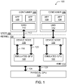
- FIG. 1 is a block diagram of a computing system 100 including a plurality of containers 106 on the user side 102. Each of the containers 106 is communicatively coupled with an emulated GPU 122 on the kernel side 104 of the computing system 100. Each container 106 may include a user-mode GPU driver (UMD) 110 and one or more software applications 108 in communication with the UMD 110.
- UMD user-mode GPU driver
- a UMD 110 may communicate with an emulated GPU 122 of a kernel-mode GPU driver (KMD) 114 via a UMD-KMD interface 112 and a device node 116 (e.g., /dev/dri/card0 or another card number in a Linux system).
- KMD kernel-mode GPU driver
- the KMD 114 may be communicatively coupled to a physical GPU 128.
- the device node 116 may exchange control data over a control path 118 (e.g., mode setting, resolution, cache mode, etc.) and render data over a render path 120 (e.g., through a command buffer containing GPU commands to be parsed by a GPU) with the emulated GPU 122.
- the KMD 114 may exchange control data over a control path 124 and render data over a render path 126 with the physical GPU 128.
- the control path 124 and the render path 126 may duplex and share a common path.
- any of a number of known techniques may be used to generate the emulated GPU 122.
- approaches like XenGT have been used to enable GPU acceleration in a VM by generating a full emulated GPU device model in a Linux graphics driver.
- This GPU device model may be used to provide the emulated GPU 122, and may be readily ported to any operating system.
- the operation of the emulated GPU 122 may be expected to be close to native performance for typical graphics workloads, an almost identical to native performance for typical media workloads.
- the trap overhead incurred during hypervisor usage is avoided by using containers instead of VMs (since containers can directly call into the emulated GPU device model from the driver code).
- XenGT is discussed above, any suitable existing GPU device model may be used to generate the emulated GPU, and thus techniques for generating an emulated GPU are not discussed further herein.
- the KMD 114 is configured to create the one or more emulated GPUs 122 and the corresponding one or more device nodes 116.
- each device node 116 is associated with a single corresponding user-side container 106, and enables communication between the user-side container 106 and the corresponding emulated GPU 122 to allow the one or more applications 108 of the user-side container 106 to utilize the graphics processing resources of the physical GPU 128.
- the computing system 100 may include a graphics memory (not shown) partitioned among multiple emulated GPUs 122.
- the graphics memory may be utilized for pixel loading or as a write command buffer, for example.
- the graphics memory for the emulated GPUs 122 may be dynamically and centrally allocated in the KMD 114 (e.g., as is conventionally done for host applications).
- the emulated GPU 122 emulates the physical GPU 128.
- the emulated GPU 122 may support a set of features that is a proper subset of the features supported by the physical GPU 128.
- the emulated GPU 122 may represent a GPU that is "simplified" relative to the physical GPU 128 (e.g., exposing fewer features to the user space than the physical GPU 128).
- the emulated GPU 122 does not emulate the physical GPU 128; examples of such embodiments are discussed below with reference to FIG. 4 .
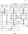
- FIG. 2 is a block diagram of an embodiment of the computing system 100 of FIG. 1 having a display manager 134 and a scheduler 130, in accordance with various embodiments.
- the computing system 100 of FIG. 2 includes a plurality of containers 106 on the user side 102, each communicatively coupled with an emulated GPU 122 on the kernel side 104.
- Each container 106 may include a user-mode GPU driver (UMD) 110 and one or more software applications 108 in communication with the UMD 110.
- the UMD 110 may in turn communicate with an emulated GPU 122 of a KMD 114 via a UMD-KMD interface 112 and a device node 116.
- UMD user-mode GPU driver
- the KMD 114 may be communicatively coupled to a physical GPU 128.
- the device node 116 may exchange control data over the control path 118 and render data over the render path 120 with the emulated GPU 122.
- the KMD 114 may exchange control data over the control path 124 and render data over the render path 126 with the physical GPU 128.
- the KMD 114 may be configured to create the one or more emulated GPUs 122 and the corresponding one or more device nodes 116.
- each device node 116 may be associated with a single corresponding user-side container 106, and may enable communication between the user-side container 106 and the corresponding emulated GPU 122 to allow the one or more applications 108 of the user-side container 106 to utilize the graphics processing resources of the physical GPU 128.
- the one or more emulated GPUs 122 may be included in a self-emulator 132, along with a display manager 134, of the KMD 114.
- the self-emulator 132 may be configured to generate a GPU device model to serve as the emulated GPU 122.
- the emulated GPU 122 may be generated with the same or equivalent features as the physical GPU 128, the KMD for the physical GPU 128 (i.e., the KMD 114) is able to generate multiple driver instances to manage both the emulated GPUs 122 and the physical GPU 128.
- the emulated GPU 122 may include exactly equivalent features as the physical GPU 128, and thus the same graphics driver can run seamlessly on both.
- Each driver instance may include its own device node 116, which may be exclusively assigned to a particular container 106, as discussed above. Minimal changes may be made to convert low-level driver input/output interfaces (e.g., i915_read/write IOCTLs) into callbacks directly into the emulated GPU 122.
- Each container 106 may be constrained to only access its own emulated GPU 122, and the self-emulator 132 may ensure that an emulated GPU 122 can't interfere with other emulated GPUs 122 (e.g., by controlling a CPU page table mapping and scanning GPU commands).
- the computing system 100 may also include one or more applications 136 and a UMD 138 that are not included in a software container.
- the applications 136 may communicate with the UMD 138, which may in turn communicate with the device node 116 of the KMD 114 via a UMD-KMD interface 140.
- the device node 116 may then exchange control data with the physical GPU 128 and render data with the scheduler 130 in accordance with conventional techniques (e.g., without going through an emulated GPU).
- a computing system 100 may accommodate both containerized and non-containerized applications (simultaneously or at different times) in utilizing the resources of the physical GPU 128.
- the KMD 114 may include a scheduler 130.
- the scheduler 130 may be communicatively coupled with the emulated GPUs 122 and the physical GPU 128.
- the scheduler 130 may provide render data over the render path 142.
- the scheduler 130 may provide a command submission interface for the emulated GPUs 122 and may implement cgroup or similar functionality.
- the scheduler 130 may be configured to enforce a quality of service policy on use of the physical GPU 128 by the emulated GPUs 122 (e.g., by applying a cgroup policy in a similar manner as conventionally performed for host applications).
- a quality of service policy may include different weights allocated to different ones of the emulated GPUs 122, based on service level agreements reached between end user and a cloud service provider about the container capability.
- the scheduler 130 may then schedule commands from each emulated GPU 122 based on the allocated weights (e.g., with a particular emulated GPU 122 being allocated a percentage of resources based on its percentage of the total weight), or using any suitable conventional technique for quality of service scheduling.
- the scheduler 130 may be configured to enforce a secure isolation policy for the emulated GPUs 122.
- an "isolation policy" may refer to a stored set of requirements regarding the allowable interaction and/or exposure of the operation of one emulated GPU 122 to another emulated GPU 122.
- the self-emulator 132 of the KMD 114 may include a display manager 134.
- the display manager 134 may couple with frame buffers (not shown) of each of the plurality of user-side containers 106 to selectively bring different ones of the frame buffers to the control path 124 for the physical GPU 128.
- This feature may be particularly advantageous in settings in which each of multiple containers 106 runs a full graphics stack (e.g., including x-server and a window manager). Such settings may occur in tablet and phone virtualization, or In-Vehicle Infotainment (IVI) virtualization.
- IVI In-Vehicle Infotainment
- the second container When a user wishes to switch from viewing the content of a first container to viewing the content of a second container, the second container may be brought to the "foreground” by bringing the frame buffer of the second container to the control path 124 for the physical GPU 128 (and the first container may be sent to the "background” by decoupling the frame buffer from the control path 124).
- Frame buffers may be brought to the control path 124 via a full mode setting or through a frame buffer switch and panel fitting, for example (with the latter typically faster than the former).
- the computing system 100 of FIG. 2 may include a graphics memory (not shown) partitioned among multiple emulated GPUs 122.
- the graphics memory may be utilized for pixel loading or as a write command buffer, for example.
- the emulated GPU 122 of FIG. 2 may emulate the physical GPU 128.
- the emulated GPU 122 may support a set of features that is a proper subset of the features supported by the physical GPU 128.
- the emulated GPU 122 does not emulate the physical GPU; examples of such embodiments are discussed below with reference to FIG. 4 .
- FIG. 3 is a block diagram of an embodiment of the computing system 100 of FIG. 1 having a virtual machine (VM) 150 communicatively coupled with an emulated GPU 122, in accordance with various embodiments.
- the computing system 100 of FIG. 1 may be based on a Type-2 hypervisor model.
- the computing system 100 of FIG. 3 includes a plurality of containers 106 on the user side 102 of a host computing device 144, each communicatively coupled with an emulated GPU 122 on the kernel side 104.
- Each container 106 may include a user-mode GPU driver (UMD) 110 and one or more software applications 108 in communication with the UMD 110.
- UMD user-mode GPU driver
- the UMD 110 may in turn communicate with an emulated GPU 122 of a KMD 114 of the host computing device 144 via a UMD-KMD interface 112 and a device node 116.
- the KMD 114 may be communicatively coupled to a physical GPU 128.
- the device node 116 may exchange control data over the control path 118 and render data over the render path 120 with the emulated GPU 122.
- the KMD 114 may exchange control data over the control path 124 and render data over the render path 126 with the physical GPU 128.
- the KMD 114 may be configured to create the one or more emulated GPUs 122 and the corresponding one or more device nodes (116.
- each device node 116 may be associated with a single corresponding user-side container 106, and may enable communication between the user-side container 106 and the corresponding emulated GPU 122 to allow the one or more applications 108 of the user-side container 106 to utilize the graphics processing resources of the physical GPU 128.
- the one or more emulated GPUs 122 may be included in a self-emulator 132, along with a display manager 134, of the KMD 114 of the host computing device 144.
- the computing system 100 may also include one or more applications 136 and a UMD 138 that are not included in a software container of the host computing device 144, as discussed above with reference to FIG. 2 .
- the KMD 114 may include a scheduler 130 and/or a display manager 134, which may take the form of any of the embodiments discussed above with reference to FIG. 2 .
- the computing system 100 of FIG. 2 may include a graphics memory (not shown) partitioned among multiple emulated GPUs 122.
- the graphics memory may be utilized for pixel loading or as a write command buffer, for example.
- the emulated GPU 122 of FIG. 2 may emulate the physical GPU 128.
- the emulated GPU 122 may support a set of features that is a proper subset of the features supported by the physical GPU 128.
- the emulated GPU 122 does not emulate the physical GPU; examples of such embodiments are discussed below with reference to FIG. 4 .
- the computing system 100 of FIG. 3 may include a VM 150.
- the VM 150 may include one or more software applications 158 in communication with a UMD 160.
- the VM 150 may also include a KMD 164 having a device node 166.
- the UMD 160 may be in communication with the device node 166 in a similar manner as discussed above with reference to the UMD 110 and the device node 116.
- the VM 150 may be running on a hypervisor 170, which may be communicatively arranged between the VM 150 and the host computing device 144.
- the hypervisor 170 may be communicatively coupled to one of the emulated GPUs 122 and may facilitate the passing of control data over the control path 178 and render data over the render path 180 from the KMD 164 to the emulated GPU 122.
- the computing system 100 of FIG. 3 may accommodate both containerized and VM-based applications (simultaneously or at different times) in utilizing the resources of the physical GPU 128. This mixed usage or "hybrid" scenario provides new flexibility in configuring the computing system 100.
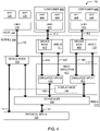
- FIG. 4 is a block diagram of an embodiment of the computing system 100 of FIG. 1 having multiple kernel-mode drivers arranged in a "nested" configuration, in accordance with various embodiments.
- the computing system 100 of FIG. 4 includes a physical GPU designated as physical GPU-A 128.
- the computing system 100 of FIG. 4 also includes a container 406 on the user side 102 communicatively coupled with an emulated GPU designated as emulated GPU-B 422 on the kernel side 104.
- the computing system 100 of FIG. 4 also includes a container 446 on the user side 102 communicatively coupled with an emulated GPU designated as emulated GPU-C 472 on the kernel side 104.
- GPU-A, GPU-B, and GPU-C may represent different GPUs (e.g., GPUs with different capabilities and associated different drivers).
- the use of three different GPUs in the computing system 100 of FIG. 4 is simply illustrative, and any suitable number of GPUs may be used in accordance with the techniques discussed herein.
- the container 406 may include a UMD 410 and one or more software applications 408 in communication with the UMD 410.
- the UMD 410 may communicate with a device node 416 of a KMD for emulated GPU-B 422 (designated as KMD-B 414) on the kernel side 104 via a UMD-KMD interface 412.
- the device node 416 may be disposed between the UMD 410 and the emulated GPU-B 422 along the communication pathway between the applications 408 and the physical GPU-A 128.
- the KMD-B 414 communicates with the emulated GPU-B 422 to exchange control data over the control path 418 and render data over the render path 420.
- the emulated GPU-B 422 may be included in a self-emulator 432 of a KMD for the physical GPU-A 128 (designated as KMD-A 114).
- the container 446 may include a UMD 460 and one or more software applications 448 in communication with the UMD 460.
- the UMD 460 may communicate with a device node 466 of a KMD for emulated GPU-C 472 (designated as KMD-C 464) on the kernel side 104 via a UMD-KMD interface 462.
- the device node 466 may be disposed between the UMD 460 and the emulated GPU-C 472 along the communication pathway between the applications 448 and the physical GPU-A 128.
- the KMD-C 464 communicates with the emulated GPU-C 472 to exchange control data over the control path 468 and render data over the render path 470.
- the emulated GPU-C 472 may be included in the self-emulator 432 of the KMD-A 114.
- the KMD-A 114 may be communicatively coupled to the physical GPU-A 128.
- the KMD-A 114 may exchange control data over the control path 124 and render data over the render path 126 with the physical GPU-A 128.
- the KMD-A 114 may be configured to create the one or more emulated GPUs (422 and 472) and the corresponding one or more device nodes (416 and 466).
- each device node (416 and 466) may be associated with a single corresponding user-side container (406 and 446, respectively), and may enable communication between the user-side container (406 and 446, respectively) and the corresponding emulated GPU (422 and 472, respectively) to allow the one or more applications (408 and 448, respectively) of the user-side containers (406 and 446, respectively) to utilize the graphics processing resources of the physical GPU-A 128.
- the self-emulator 432 may include a display manager 134, as discussed above.
- the computing system 100 may also include one or more applications 136 and a UMD 138 that are not included in a software container of the host device 144, as discussed above with reference to FIG. 2 .
- the KMD-A 114 may include a scheduler 130 and/or a display manager 134, which may take the form of any of the embodiments discussed above with reference to FIG. 2 .
- the computing system 100 of FIG. 2 may include a graphics memory (not shown) partitioned among multiple emulated GPUs (e.g., the emulated GPUs 422 and 472).
- the graphics memory may be utilized for pixel loading or as a write command buffer, for example.
- the emulated GPU 122 of FIG. 2 may emulate the physical GPU 128.
- the emulated GPU-B 422 may not emulate the physical GPU-A 128.
- the emulated GPU-C 472 may not emulate the physical GPU-A 128, and the GPUs emulated by the emulated GPU-B 422 and the emulated GPU-C 472 may not be the same GPU.
- different graphics drivers can run on the emulated GPUs 122. Additional translation may be applied for, e.g., command formats and display attributes.
- the hybrid VM-container approach discussed above with reference to FIG. 3 and the nested driver approach discussed above with reference to FIG. 4 may be combined in a single computing system in any desired arrangement. More generally, any suitable ones of the embodiments disclosed herein may be combined with other embodiments disclosed herein to generate a computing system within the scope of the present disclosure.
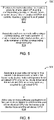
- FIG. 5 is a flow diagram of a kernel-side method 500 for enabling user-side containers to utilize resources of a physical GPU, in accordance with various embodiments.
- the method 500 may be discussed below with reference to the computing system 100. It may be recognized that, while the operations of the method 500 (and the other methods described herein) are arranged in a particular order and illustrated once each, in various embodiments, one or more of the operations may be repeated, omitted, or performed out of order. For illustrative purposes, operations of the method 500 may be described as performed by circuitry on the kernel side 104 of the computing system 100, but the method 500 may be performed by any suitably configured device.
- circuitry on the kernel side 104 of the computing system 100 may provide a KMD (e.g., the KMD 114) to create a plurality of emulated GPUs (the emulated GPUs 122) and a corresponding plurality of device nodes (e.g., the device nodes 116).
- the plurality of emulated GPUs may be communicatively coupled to a physical GPU (e.g., the physical GPU 128).
- circuitry on the kernel side 104 of the computing system 100 may associate each device node with a single corresponding user-side container (e.g., a container 106) to enable communication between the user-side container and the corresponding emulated GPU to utilize resources of the physical GPU.
- a single corresponding user-side container e.g., a container 106
- FIG. 6 is a flow diagram of a user-side method 600 for enabling user-side containers to utilize resources of a physical GPU, in accordance with various embodiments.
- the method 600 may be discussed below with reference to the computing system 100.
- operations of the method 600 may be described as performed by circuitry on the user side 102 of the computing system 100, but the method 600 may be performed by any suitably configured device.
- circuitry on the user side 102 of the computing system 100 may associate a user-side container (e.g., a container 106) with a kernel-side device node (e.g., a device node 116).
- the kernel-side device node may correspond to an emulated GPU (e.g., an emulated GPU 122) of a KMD (e.g., the KMD 114) and the emulated GPU may be communicatively coupled to the physical GPU (e.g., the physical GPU 128).
- circuitry on the user side 102 of the computing system 100 may allow one or more software applications (e.g., a software application 108) in the user-side container to utilize a resource of the physical GPU via the kernel-side device node and the emulated GPU.
- software applications e.g., a software application 108
- Suitable ones of the embodiments disclosed herein may be readily applied to computing systems in which the physical GPU 128 is a single-root input/output virtualization (SR-IOV)-capable GPU.
- Multiple emulated GPUs e.g., the emulated GPUs 122
- the emulated device approach disclosed herein may be extended beyond emulated GPUs, and may be used to containerize other subsystems, such as storage. This may remedy some of the deficiencies of existing approaches to managing these subsystems. For example, existing mount namespace techniques do not provide quantum control across containers, and extending a file system is a complex task. However, generating emulated storage devices may address these deficiencies and provide a straightforward solution.
- FIG. 7 is a block diagram of an example computing device 700, which may be suitable for practicing various disclosed embodiments.
- the computing device 700 may serve as the computing system 100 or as the host computing device 144.
- the components of the computing device 700 may be distributed across multiple physical device housings or locations, while in other embodiments, the components of the computing device 700 may be included in a single housing or location.
- the computing device 700 may include a number of components, including one or more processor(s) 704 and at least one communication chip 706.
- the processor 704 may include a processor core.
- at least one communication chip 706 may also be physically and electrically coupled to the processor 704.
- the communication chip 706 may be part of the processor 704.
- the computing device 700 may include a printed circuit board (PCB) 702.
- PCB printed circuit board
- the processor 704 and the communication chip 706 may be disposed thereon.
- the various components may be coupled without the employment of the PCB 702.
- the computing device 700 may include other components that may or may not be physically and electrically coupled to the PCB 702. These other components include, but are not limited to, random access memory (RAM) 708, volatile memory (such as dynamic RAM (DRAM)), non-volatile memory (e.g., read-only memory 710, also referred to as "ROM," one or more hard disk drives, one or more solid-state drives, one or more compact disc drives, and/or one or more digital versatile disc drives), flash memory 712, input/output (I/O) controller 714, a digital signal processor (not shown), a crypto processor (not shown), graphics processor 716 (e.g., the physical GPU 128), one or more antenna 718, touch screen display 720, touch screen controller 722, other displays (such as liquid-crystal displays, cathode-ray tube displays, and e-ink displays, not shown), battery 724, an audio codec (not shown), a video codec (not shown), global positioning
- RAM random access memory
- DRAM dynamic RAM
- the processor 704 may be integrated on the same die with other components to form a System on Chip (SoC).
- SoC System on Chip
- Any of the memory devices discussed herein may include any one or more of the memory devices illustrated in FIG. 7 or discussed herein with reference to FIG. 7 .
- volatile memory e.g., RAM 708, non-volatile memory (e.g., ROM 710), flash memory 712, and the mass storage device may include instructions that, in response to execution by the one or more processor(s) 704, cause the computing device 700 to practice all or selected aspects of the processes described herein with reference to FIGS. 1-6 .
- one or more of the memory components may be computer readable media that include temporal and/or persistent (e.g., non-transitory) copies of instructions that, in response to execution by the one or more processor(s) 704, cause the computing device 700 to practice all or selected aspects of the processes described herein.
- Memory accessible to the computing device 700 may include one or more storage devices that are physically part of a device on which the computing device 700 is installed and/or one or more storage devices that are accessible by, but not necessarily a part of, the computing device 700.
- a storage device may be accessed by the computing device 700 over a network via the communication chip 706.
- the instructions may be embodied in a computer-readable transitory non-tangible medium, such as signals.
- the communication chip 706 may enable wired and/or wireless communications for the transfer of data to and from the computing device 700.
- wireless and its derivatives may be used to describe circuits, devices, systems, methods, techniques, communication channels, etc., that may communicate data through the use of modulated electromagnetic radiation through a non-solid medium. The term does not imply that the associated devices do not contain any wires, although in some embodiments they might not.
- the communication chip 706 may implement any of a number of wireless standards or protocols, including but not limited to IEEE02.20, General Packet Radio Service (GPRS), Evolution Data Optimized (Ev-DO), Evolved High Speed Packet Access (HSPA+), Evolved High Speed Downlink Packet Access (HSDPA+), Evolved High Speed Uplink Packet Access (HSUPA+), Global System for Mobile Communications (GSM), Enhanced Data rates for GSM Evolution (EDGE), Code Division Multiple Access (CDMA), Time Division Multiple Access (TDMA), Digital Enhanced Cordless Telecommunications (DECT), Bluetooth, Wi-Fi, Long Term Evolution (LTE), derivatives thereof, as well as any other wireless protocols that are designated as 2G, 3G, 4G, and beyond.
- GPRS General Packet Radio Service
- Ev-DO Evolution Data Optimized
- HSPA+ High Speed Packet Access
- HSDPA+ Evolved High Speed Downlink Packet Access
- HSUPA+ High Speed Uplink Packet Access
- the computing device 700 may include a plurality of communication chips 706.
- a first communication chip 706 may be dedicated to shorter range wireless communications such as Wi-Fi and Bluetooth and a second communication chip 706 may be dedicated to longer range wireless communications such as GPS, EDGE, GPRS, CDMA, WiMAX, LTE, Ev-DO, and others.
- the computing device 700 may be a laptop, a netbook, a notebook, an ultrabook, a wearable device, a smartphone, a computing tablet, a personal digital assistant, an ultra mobile PC, a mobile phone, a desktop computer, a server, a printer, a scanner, a monitor, a set-top box, an entertainment control unit (e.g., a gaming console), a digital camera, a portable music player, or a digital video recorder.
- the computing device 700 may be any other electronic device that processes data.
Landscapes
- Engineering & Computer Science (AREA)
- Theoretical Computer Science (AREA)
- Software Systems (AREA)
- Physics & Mathematics (AREA)
- General Physics & Mathematics (AREA)
- General Engineering & Computer Science (AREA)
- Stored Programmes (AREA)
- Image Generation (AREA)
- Digital Computer Display Output (AREA)
Description
- Embodiments of the present disclosure generally relate to the field of computing systems, and more particularly, to container access to graphics processing unit resources.
- Containers have been used to access non-graphics processing unit (GPU) computing resources, such as central processing unit (CPU) resources, memory and storage, and network functions. However, the unique issues involved in the use of containers in GPU-heavy applications have left GPU containerization an open challenge.
- Prior art document
US 2013/091500 discloses a virtualized computation environment executing within a computer system, the system including a privileged virtual machine (VM), a set of guest virtual machines and a virtualization layer, the privileged VM including hardware emulation software, a GPU emulation module plugged into the hardware emulation software that includes a display emulation module, and a master resource manager (RM). - The invention is laid out in the appended independent claims. The appended dependent claims represent preferred embodiments of the invention.
- Embodiments will be readily understood by the following detailed description in conjunction with the accompanying drawings. To facilitate this description, like reference numerals designate like structural elements. Embodiments are illustrated by way of example and not by way of limitation in the figures of the accompanying drawings.
-
FIG. 1 is a block diagram of a computing system including a container communicatively coupled with an emulated GPU, in accordance with various embodiments. -
FIG. 2 is a block diagram of an embodiment of the computing system ofFIG. 1 having a display manager and a scheduler, in accordance with various embodiments. -
FIG. 3 is a block diagram of an embodiment of the computing system ofFIG. 1 having a virtual machine communicatively coupled with an emulated GPU, in accordance with various embodiments. -
FIG. 4 is a block diagram of an embodiment of the computing system ofFIG. 1 having multiple kernel-mode drivers, in accordance with various embodiments. -
FIG. 5 is a flow diagram of a kernel-side method for enabling user-side containers to utilize resources of a physical GPU, in accordance with various embodiments. -
FIG. 6 is a flow diagram of a user-side method for enabling user-side containers to utilize resources of a physical GPU, in accordance with various embodiments. -
FIG. 7 is a block diagram of an example computing device that may be used to practice various embodiments described herein. - Disclosed herein are systems and methods for container access to graphics processing unit (GPU) resources, in particular a method for enabling a plurality of software containers to utilize resources of a physical graphics processing unit, GPU, the method comprising: providing a kernel-mode driver to create a plurality of emulated GPUs and a corresponding plurality of device nodes enabling communication between the containers and the emulated GPUs; and associating each device node with a single corresponding container to enable communication between the container and the corresponding emulated GPU to utilize resources of the physical GPU such that each one of the plurality of emulated GPU s is associated with a unique one of the plurality of device nodes, exclusively owned by a single one of the containers, and such that each of the containers can only access its own emulated GPU.
- Various ones of the embodiments disclosed herein may provide GPU acceleration in containers through driver self-emulation. Containers, also referred to as "software containers," provide operating system-level virtualization in a computing system. Systems that utilize containers instead of traditional virtual machines (VMs) may exhibit higher density, faster provisioning, and better performance, making containers a strong lightweight alternative to virtualization technology in certain applications.
- As noted above, containers have been used to access non-GPU computing resources, such as central processing unit (CPU) resources, memory and storage, and network functions. These subsystems are managed by the kernel, and typically have well-abstracted resources and a simple interface exposed to the user side of the computing system. In particular, different namespaces may give each user-side process a separate view of the system, isolated from other processes and including separate mount points, process identifiers (PIDs), interprocess communication (IPC), network resources, and time resources, among others. The result is that the namespace enables the containerization of these non-GPU computing resources for an individual user. The "cgroup" functionality in the Linux kernel limits, accounts for, and isolates resource usage of multiple processes, and may further enforce resource limitation, prioritization, accounting, and control among different namespaces. Consequently, multiple containers may be well isolated.
- However, the unique issues involved in the use of containers in GPU-heavy applications have been an open challenge. In particular, the complex interface between the kernel-mode driver (KMD) and the user-mode driver (UMD) of a GPU has meant that a graphics subsystem is much more complex than the subsystems discussed above. Interfaces and graphics subsystems are usually vendor-specific, so the resources exposed to the UMD are poorly abstracted, requiring more options to be specified than with the subsystems discussed above by orders of magnitude. For example, atypical graphics driver in Linux may include approximately 70 common direct rendering manager (DRM) input/output control (IOCTL) options and approximately 40 vendor-specific IOCTL options. Each IOCTL leads to complex code paths in the graphics driver, which finally translate to thousands of registers in the GPU. Creating a namespace or utilizing cgroup for such a large interface and set of device attributes requires a very detailed, intrusive, and device-specific set of modifications touching almost every code path/data structure within a KMD. This is a tremendous amount of engineering effort, and may present an almost unmanageable maintenance burden. Moreover, the ability to port a solution for one GPU to another GPU is limited or nonexistent.
- These challenges have limited or precluded the use of containers in graphics-intensive scenarios. These scenarios may include the use of multiple personalities and client devices (e.g., personal computer, phone, tablet); remote desktops or workstations running GPU-intensive computer aided drafting (CAD) software; media delivery cloud applications that provide media transcoding, videoconference, clouds set-top box, or other software as a service; cloud gaming; and visual understanding (e.g., face recognition, deep learning, etc.) . Some of these scenarios may require full GPU capabilities (e.g., three-dimensional graphics, video, and GPU computations), and others of these scenarios may require only part of the capabilities of a GPU. Conventionally, hypervisor-based virtualization (e.g., running a whole operating system in a virtual machine) is used in these scenarios.
- At best, "containerization" has been attempted only by exclusively assigning a physical GPU to a single container without the ability of multiple containers to share the resources of that GPU. Some previous approaches have attempted to run applications in multiple containers, and have these applications access GPU resources, but the applications of the different containers have not been isolated from each other and thereby present a significant security risk.
- Some of the embodiments disclosed herein provide container graphics in a secure, isolated manner enabling good quality of service (QOS) control. In particular, a driver self-emulation approach is disclosed herein in which multiple emulated GPU instances may be generated. Each GPU instance may be securely isolated and dedicated when used by a user-side container. This may enable GPU acceleration in containers with robust isolation in both security and performance. Using the approach disclosed herein, the difficulty of containerizing a UMD with a complex interface to a KMD is eliminated; instead, emulated GPUs may be containerized and communicate with a physical GPU using known techniques.
- In some embodiments, an emulated GPU in a computing system is generated by the KMD. The emulated GPU may have the same features as a physical GPU in the computing system. Each emulated GPU is associated with a unique device node that is exclusively owned by a single container on the user side. The same driver code may run on top of an emulated GPU and the physical GPU (e.g., with substantially identical low-level input/output hooks). Secure isolation may be centrally enforced at the emulated GPU level (e.g., in a self-emulator). Each container can only access its own emulated GPU, so strict isolation can be achieved. Performance isolation may be enforced when emulated GPU issues GPU commands to a scheduler, which can then extend existing QOS policy enforcement techniques to the applications in the container. Various ones of these and other embodiments are discussed in detail herein.
- In the following detailed description, reference is made to the accompanying drawings, which form a part hereof wherein like numerals designate like parts throughout, and in which is shown by way of illustration embodiments that may be practiced. It is to be understood that other embodiments may be utilized and structural or logical changes may be made without departing from the scope of the present disclosure.
- Various operations may be described as multiple discrete actions or operations in turn, in a manner that is most helpful in understanding the claimed subject matter. However, the order of description should not be construed as to imply that these operations are necessarily order dependent. In particular, these operations may not be performed in the order of presentation. Operations described may be performed in a different order than the described embodiment. Various additional operations may be performed or described operations may be omitted in additional embodiments.
- For the purposes of the present disclosure, the term "or" is used as an inclusive term to mean at least one of the components coupled with the term. For example, the phrase "A or B" means (A), (B), or (A and B); and the phrase "A, B, or C" means (A), (B), (C), (A and B), (A and C), (B and C), or (A, B, and C).
- The description may use the phrases "in an embodiment," or "in embodiments," which may each refer to one or more of the same or different embodiments. Furthermore, the terms "comprising," "including," "having," and the like, as used with respect to embodiments of the present disclosure, are synonymous.
- As used herein, the term "circuitry" may refer to, be part of, or include an Application Specific Integrated Circuit (ASIC), an electronic circuit, a processor (shared, dedicated, or group), or memory (shared, dedicated, or group) that execute one or more software or firmware programs, a combinational logic circuit, or other suitable hardware components that provide the described functionality. As used herein, the terms "driver" and "driver circuitry" may include circuitry programmed or otherwise structured to operate and/or control a particular hardware device (e.g., a graphics processing unit).
-
FIG. 1 is a block diagram of acomputing system 100 including a plurality ofcontainers 106 on the user side 102. Each of thecontainers 106 is communicatively coupled with an emulatedGPU 122 on thekernel side 104 of thecomputing system 100. Eachcontainer 106 may include a user-mode GPU driver (UMD) 110 and one ormore software applications 108 in communication with theUMD 110. AUMD 110 may communicate with an emulatedGPU 122 of a kernel-mode GPU driver (KMD) 114 via a UMD-KMD interface 112 and a device node 116 (e.g., /dev/dri/card0 or another card number in a Linux system). TheKMD 114 may be communicatively coupled to aphysical GPU 128. Thedevice node 116 may exchange control data over a control path 118 (e.g., mode setting, resolution, cache mode, etc.) and render data over a render path 120 (e.g., through a command buffer containing GPU commands to be parsed by a GPU) with the emulatedGPU 122. In turn, theKMD 114 may exchange control data over acontrol path 124 and render data over a renderpath 126 with thephysical GPU 128. In some embodiments, thecontrol path 124 and the renderpath 126 may duplex and share a common path. - Any of a number of known techniques may be used to generate the emulated
GPU 122. For example, approaches like XenGT have been used to enable GPU acceleration in a VM by generating a full emulated GPU device model in a Linux graphics driver. This GPU device model may be used to provide the emulatedGPU 122, and may be readily ported to any operating system. Using the XenGT approach, the operation of the emulatedGPU 122 may be expected to be close to native performance for typical graphics workloads, an almost identical to native performance for typical media workloads. Additionally, the trap overhead incurred during hypervisor usage is avoided by using containers instead of VMs (since containers can directly call into the emulated GPU device model from the driver code). Although XenGT is discussed above, any suitable existing GPU device model may be used to generate the emulated GPU, and thus techniques for generating an emulated GPU are not discussed further herein. - The
KMD 114 is configured to create the one or more emulatedGPUs 122 and the corresponding one ormore device nodes 116. In use, eachdevice node 116 is associated with a single corresponding user-side container 106, and enables communication between the user-side container 106 and the corresponding emulatedGPU 122 to allow the one ormore applications 108 of the user-side container 106 to utilize the graphics processing resources of thephysical GPU 128. - In some embodiments, the
computing system 100 may include a graphics memory (not shown) partitioned among multiple emulatedGPUs 122. The graphics memory may be utilized for pixel loading or as a write command buffer, for example. In other embodiments, the graphics memory for the emulatedGPUs 122 may be dynamically and centrally allocated in the KMD 114 (e.g., as is conventionally done for host applications). - The emulated
GPU 122 emulates thephysical GPU 128. - In some embodiments, the emulated
GPU 122 may support a set of features that is a proper subset of the features supported by thephysical GPU 128. For example, the emulatedGPU 122 may represent a GPU that is "simplified" relative to the physical GPU 128 (e.g., exposing fewer features to the user space than the physical GPU 128). In some embodiments, the emulatedGPU 122 does not emulate thephysical GPU 128; examples of such embodiments are discussed below with reference toFIG. 4 . -
FIG. 2 is a block diagram of an embodiment of thecomputing system 100 ofFIG. 1 having adisplay manager 134 and ascheduler 130, in accordance with various embodiments. As discussed above with reference toFIG. 1 , thecomputing system 100 ofFIG. 2 includes a plurality ofcontainers 106 on the user side 102, each communicatively coupled with an emulatedGPU 122 on thekernel side 104. Eachcontainer 106 may include a user-mode GPU driver (UMD) 110 and one ormore software applications 108 in communication with theUMD 110. TheUMD 110 may in turn communicate with an emulatedGPU 122 of aKMD 114 via a UMD-KMD interface 112 and adevice node 116. As noted above with reference toFIG. 1 , theKMD 114 may be communicatively coupled to aphysical GPU 128. Thedevice node 116 may exchange control data over thecontrol path 118 and render data over the renderpath 120 with the emulatedGPU 122. In turn, theKMD 114 may exchange control data over thecontrol path 124 and render data over the renderpath 126 with thephysical GPU 128. TheKMD 114 may be configured to create the one or more emulatedGPUs 122 and the corresponding one ormore device nodes 116. In use, eachdevice node 116 may be associated with a single corresponding user-side container 106, and may enable communication between the user-side container 106 and the corresponding emulatedGPU 122 to allow the one ormore applications 108 of the user-side container 106 to utilize the graphics processing resources of thephysical GPU 128. - As shown in
FIG. 2 , the one or more emulatedGPUs 122 may be included in a self-emulator 132, along with adisplay manager 134, of theKMD 114. The self-emulator 132 may be configured to generate a GPU device model to serve as the emulatedGPU 122. In embodiments in which the emulatedGPU 122 may be generated with the same or equivalent features as thephysical GPU 128, the KMD for the physical GPU 128 (i.e., the KMD 114) is able to generate multiple driver instances to manage both the emulatedGPUs 122 and thephysical GPU 128. In some embodiments, the emulatedGPU 122 may include exactly equivalent features as thephysical GPU 128, and thus the same graphics driver can run seamlessly on both. Each driver instance may include itsown device node 116, which may be exclusively assigned to aparticular container 106, as discussed above. Minimal changes may be made to convert low-level driver input/output interfaces (e.g., i915_read/write IOCTLs) into callbacks directly into the emulatedGPU 122. Eachcontainer 106 may be constrained to only access its own emulatedGPU 122, and the self-emulator 132 may ensure that an emulatedGPU 122 can't interfere with other emulated GPUs 122 (e.g., by controlling a CPU page table mapping and scanning GPU commands). - The
computing system 100 may also include one ormore applications 136 and aUMD 138 that are not included in a software container. Theapplications 136 may communicate with theUMD 138, which may in turn communicate with thedevice node 116 of theKMD 114 via a UMD-KMD interface 140. Thedevice node 116 may then exchange control data with thephysical GPU 128 and render data with thescheduler 130 in accordance with conventional techniques (e.g., without going through an emulated GPU). Thus, acomputing system 100 may accommodate both containerized and non-containerized applications (simultaneously or at different times) in utilizing the resources of thephysical GPU 128. - The
KMD 114 may include ascheduler 130. Thescheduler 130 may be communicatively coupled with the emulatedGPUs 122 and thephysical GPU 128. Thescheduler 130 may provide render data over the renderpath 142. Thescheduler 130 may provide a command submission interface for the emulatedGPUs 122 and may implement cgroup or similar functionality. In some embodiments, thescheduler 130 may be configured to enforce a quality of service policy on use of thephysical GPU 128 by the emulated GPUs 122 (e.g., by applying a cgroup policy in a similar manner as conventionally performed for host applications). For example, a quality of service policy may include different weights allocated to different ones of the emulatedGPUs 122, based on service level agreements reached between end user and a cloud service provider about the container capability. Thescheduler 130 may then schedule commands from each emulatedGPU 122 based on the allocated weights (e.g., with a particular emulatedGPU 122 being allocated a percentage of resources based on its percentage of the total weight), or using any suitable conventional technique for quality of service scheduling. In some embodiments, thescheduler 130 may be configured to enforce a secure isolation policy for the emulatedGPUs 122. As used herein, an "isolation policy" may refer to a stored set of requirements regarding the allowable interaction and/or exposure of the operation of one emulatedGPU 122 to another emulatedGPU 122. - The self-
emulator 132 of theKMD 114 may include adisplay manager 134. Thedisplay manager 134 may couple with frame buffers (not shown) of each of the plurality of user-side containers 106 to selectively bring different ones of the frame buffers to thecontrol path 124 for thephysical GPU 128. This feature may be particularly advantageous in settings in which each ofmultiple containers 106 runs a full graphics stack (e.g., including x-server and a window manager). Such settings may occur in tablet and phone virtualization, or In-Vehicle Infotainment (IVI) virtualization. When a user wishes to switch from viewing the content of a first container to viewing the content of a second container, the second container may be brought to the "foreground" by bringing the frame buffer of the second container to thecontrol path 124 for the physical GPU 128 (and the first container may be sent to the "background" by decoupling the frame buffer from the control path 124). Frame buffers may be brought to thecontrol path 124 via a full mode setting or through a frame buffer switch and panel fitting, for example (with the latter typically faster than the former). - As noted above with reference to
FIG. 1 , in some embodiments, thecomputing system 100 ofFIG. 2 may include a graphics memory (not shown) partitioned among multiple emulatedGPUs 122. The graphics memory may be utilized for pixel loading or as a write command buffer, for example. In some embodiments, the emulatedGPU 122 ofFIG. 2 may emulate thephysical GPU 128. In some embodiments, the emulatedGPU 122 may support a set of features that is a proper subset of the features supported by thephysical GPU 128. In some embodiments, the emulatedGPU 122 does not emulate the physical GPU; examples of such embodiments are discussed below with reference toFIG. 4 . -
FIG. 3 is a block diagram of an embodiment of thecomputing system 100 ofFIG. 1 having a virtual machine (VM) 150 communicatively coupled with an emulatedGPU 122, in accordance with various embodiments. Thecomputing system 100 ofFIG. 1 may be based on a Type-2 hypervisor model. As discussed above with reference toFIG. 1 , thecomputing system 100 ofFIG. 3 includes a plurality ofcontainers 106 on the user side 102 of ahost computing device 144, each communicatively coupled with an emulatedGPU 122 on thekernel side 104. Eachcontainer 106 may include a user-mode GPU driver (UMD) 110 and one ormore software applications 108 in communication with theUMD 110. TheUMD 110 may in turn communicate with an emulatedGPU 122 of aKMD 114 of thehost computing device 144 via a UMD-KMD interface 112 and adevice node 116. As noted above with reference toFIG. 1 , theKMD 114 may be communicatively coupled to aphysical GPU 128. Thedevice node 116 may exchange control data over thecontrol path 118 and render data over the renderpath 120 with the emulatedGPU 122. In turn, theKMD 114 may exchange control data over thecontrol path 124 and render data over the renderpath 126 with thephysical GPU 128. TheKMD 114 may be configured to create the one or more emulatedGPUs 122 and the corresponding one or more device nodes (116. In use, eachdevice node 116 may be associated with a single corresponding user-side container 106, and may enable communication between the user-side container 106 and the corresponding emulatedGPU 122 to allow the one ormore applications 108 of the user-side container 106 to utilize the graphics processing resources of thephysical GPU 128. The one or more emulatedGPUs 122 may be included in a self-emulator 132, along with adisplay manager 134, of theKMD 114 of thehost computing device 144. Thecomputing system 100 may also include one ormore applications 136 and aUMD 138 that are not included in a software container of thehost computing device 144, as discussed above with reference toFIG. 2 . TheKMD 114 may include ascheduler 130 and/or adisplay manager 134, which may take the form of any of the embodiments discussed above with reference toFIG. 2 . As noted above with reference toFIG. 1 , in some embodiments, thecomputing system 100 ofFIG. 2 may include a graphics memory (not shown) partitioned among multiple emulatedGPUs 122. The graphics memory may be utilized for pixel loading or as a write command buffer, for example. In some embodiments, the emulatedGPU 122 ofFIG. 2 may emulate thephysical GPU 128. In some embodiments, the emulatedGPU 122 may support a set of features that is a proper subset of the features supported by thephysical GPU 128. In some embodiments, the emulatedGPU 122 does not emulate the physical GPU; examples of such embodiments are discussed below with reference toFIG. 4 . - As noted above, the
computing system 100 ofFIG. 3 may include aVM 150. TheVM 150 may include one ormore software applications 158 in communication with aUMD 160. TheVM 150 may also include aKMD 164 having adevice node 166. TheUMD 160 may be in communication with thedevice node 166 in a similar manner as discussed above with reference to theUMD 110 and thedevice node 116. TheVM 150 may be running on ahypervisor 170, which may be communicatively arranged between theVM 150 and thehost computing device 144. In particular, thehypervisor 170 may be communicatively coupled to one of the emulatedGPUs 122 and may facilitate the passing of control data over thecontrol path 178 and render data over the renderpath 180 from theKMD 164 to the emulatedGPU 122. Thus, thecomputing system 100 ofFIG. 3 may accommodate both containerized and VM-based applications (simultaneously or at different times) in utilizing the resources of thephysical GPU 128. This mixed usage or "hybrid" scenario provides new flexibility in configuring thecomputing system 100. -
FIG. 4 is a block diagram of an embodiment of thecomputing system 100 ofFIG. 1 having multiple kernel-mode drivers arranged in a "nested" configuration, in accordance with various embodiments. Thecomputing system 100 ofFIG. 4 includes a physical GPU designated as physical GPU-A 128. Thecomputing system 100 ofFIG. 4 also includes acontainer 406 on the user side 102 communicatively coupled with an emulated GPU designated as emulated GPU-B 422 on thekernel side 104. Thecomputing system 100 ofFIG. 4 also includes acontainer 446 on the user side 102 communicatively coupled with an emulated GPU designated as emulated GPU-C 472 on thekernel side 104. In thecomputing system 100 ofFIG. 4 , GPU-A, GPU-B, and GPU-C may represent different GPUs (e.g., GPUs with different capabilities and associated different drivers). The use of three different GPUs in thecomputing system 100 ofFIG. 4 is simply illustrative, and any suitable number of GPUs may be used in accordance with the techniques discussed herein. - The
container 406 may include aUMD 410 and one ormore software applications 408 in communication with theUMD 410. TheUMD 410 may communicate with adevice node 416 of a KMD for emulated GPU-B 422 (designated as KMD-B 414) on thekernel side 104 via a UMD-KMD interface 412. As shown, thedevice node 416 may be disposed between theUMD 410 and the emulated GPU-B 422 along the communication pathway between theapplications 408 and the physical GPU-A 128. The KMD-B 414 communicates with the emulated GPU-B 422 to exchange control data over thecontrol path 418 and render data over the renderpath 420. The emulated GPU-B 422 may be included in a self-emulator 432 of a KMD for the physical GPU-A 128 (designated as KMD-A 114). - The
container 446 may include aUMD 460 and one ormore software applications 448 in communication with theUMD 460. TheUMD 460 may communicate with adevice node 466 of a KMD for emulated GPU-C 472 (designated as KMD-C 464) on thekernel side 104 via a UMD-KMD interface 462. As shown, thedevice node 466 may be disposed between theUMD 460 and the emulated GPU-C 472 along the communication pathway between theapplications 448 and the physical GPU-A 128. The KMD-C 464 communicates with the emulated GPU-C 472 to exchange control data over thecontrol path 468 and render data over the renderpath 470. The emulated GPU-C 472 may be included in the self-emulator 432 of the KMD-A 114. - As discussed above with reference to
FIG. 1 , the KMD-A 114 may be communicatively coupled to the physical GPU-A 128. The KMD-A 114 may exchange control data over thecontrol path 124 and render data over the renderpath 126 with the physical GPU-A 128. The KMD-A 114 may be configured to create the one or more emulated GPUs (422 and 472) and the corresponding one or more device nodes (416 and 466). In use, each device node (416 and 466) may be associated with a single corresponding user-side container (406 and 446, respectively), and may enable communication between the user-side container (406 and 446, respectively) and the corresponding emulated GPU (422 and 472, respectively) to allow the one or more applications (408 and 448, respectively) of the user-side containers (406 and 446, respectively) to utilize the graphics processing resources of the physical GPU-A 128. The self-emulator 432 may include adisplay manager 134, as discussed above. Thecomputing system 100 may also include one ormore applications 136 and aUMD 138 that are not included in a software container of thehost device 144, as discussed above with reference toFIG. 2 . The KMD-A 114 may include ascheduler 130 and/or adisplay manager 134, which may take the form of any of the embodiments discussed above with reference toFIG. 2 . As noted above with reference toFIG. 1 , in some embodiments, thecomputing system 100 ofFIG. 2 may include a graphics memory (not shown) partitioned among multiple emulated GPUs (e.g., the emulatedGPUs 422 and 472). The graphics memory may be utilized for pixel loading or as a write command buffer, for example. In some embodiments, the emulatedGPU 122 ofFIG. 2 may emulate thephysical GPU 128. - In the
computing system 100 ofFIG. 4 , the emulated GPU-B 422 may not emulate the physical GPU-A 128. Similarly, the emulated GPU-C 472 may not emulate the physical GPU-A 128, and the GPUs emulated by the emulated GPU-B 422 and the emulated GPU-C 472 may not be the same GPU. However, by using the driver-nesting approach shown, different graphics drivers can run on the emulatedGPUs 122. Additional translation may be applied for, e.g., command formats and display attributes. - In some embodiments, the hybrid VM-container approach discussed above with reference to
FIG. 3 and the nested driver approach discussed above with reference toFIG. 4 may be combined in a single computing system in any desired arrangement. More generally, any suitable ones of the embodiments disclosed herein may be combined with other embodiments disclosed herein to generate a computing system within the scope of the present disclosure. -
FIG. 5 is a flow diagram of a kernel-side method 500 for enabling user-side containers to utilize resources of a physical GPU, in accordance with various embodiments. For ease of illustration, themethod 500 may be discussed below with reference to thecomputing system 100. It may be recognized that, while the operations of the method 500 (and the other methods described herein) are arranged in a particular order and illustrated once each, in various embodiments, one or more of the operations may be repeated, omitted, or performed out of order. For illustrative purposes, operations of themethod 500 may be described as performed by circuitry on thekernel side 104 of thecomputing system 100, but themethod 500 may be performed by any suitably configured device. - At 502, circuitry on the
kernel side 104 of thecomputing system 100 may provide a KMD (e.g., the KMD 114) to create a plurality of emulated GPUs (the emulated GPUs 122) and a corresponding plurality of device nodes (e.g., the device nodes 116). The plurality of emulated GPUs may be communicatively coupled to a physical GPU (e.g., the physical GPU 128). - At 504, circuitry on the
kernel side 104 of thecomputing system 100 may associate each device node with a single corresponding user-side container (e.g., a container 106) to enable communication between the user-side container and the corresponding emulated GPU to utilize resources of the physical GPU. -
FIG. 6 is a flow diagram of a user-side method 600 for enabling user-side containers to utilize resources of a physical GPU, in accordance with various embodiments. For ease of illustration, themethod 600 may be discussed below with reference to thecomputing system 100. In particular, for illustrative purposes, operations of themethod 600 may be described as performed by circuitry on the user side 102 of thecomputing system 100, but themethod 600 may be performed by any suitably configured device. - At 602, circuitry on the user side 102 of the
computing system 100 may associate a user-side container (e.g., a container 106) with a kernel-side device node (e.g., a device node 116). The kernel-side device node may correspond to an emulated GPU (e.g., an emulated GPU 122) of a KMD (e.g., the KMD 114) and the emulated GPU may be communicatively coupled to the physical GPU (e.g., the physical GPU 128). - At 604, circuitry on the user side 102 of the
computing system 100 may allow one or more software applications (e.g., a software application 108) in the user-side container to utilize a resource of the physical GPU via the kernel-side device node and the emulated GPU. - Suitable ones of the embodiments disclosed herein may be readily applied to computing systems in which the
physical GPU 128 is a single-root input/output virtualization (SR-IOV)-capable GPU. Multiple emulated GPUs (e.g., the emulated GPUs 122) may be managed in the same manner as the virtual functions in an SR-IOV GPU system. Additionally, the emulated device approach disclosed herein may be extended beyond emulated GPUs, and may be used to containerize other subsystems, such as storage. This may remedy some of the deficiencies of existing approaches to managing these subsystems. For example, existing mount namespace techniques do not provide quantum control across containers, and extending a file system is a complex task. However, generating emulated storage devices may address these deficiencies and provide a straightforward solution. -
FIG. 7 is a block diagram of anexample computing device 700, which may be suitable for practicing various disclosed embodiments. For example, thecomputing device 700 may serve as thecomputing system 100 or as thehost computing device 144. In some embodiments, the components of thecomputing device 700 may be distributed across multiple physical device housings or locations, while in other embodiments, the components of thecomputing device 700 may be included in a single housing or location. - The
computing device 700 may include a number of components, including one or more processor(s) 704 and at least onecommunication chip 706. In various embodiments, theprocessor 704 may include a processor core. In various embodiments, at least onecommunication chip 706 may also be physically and electrically coupled to theprocessor 704. In further implementations, thecommunication chip 706 may be part of theprocessor 704. In various embodiments, thecomputing device 700 may include a printed circuit board (PCB) 702. For these embodiments, theprocessor 704 and thecommunication chip 706 may be disposed thereon. In alternate embodiments, the various components may be coupled without the employment of thePCB 702. - Depending on its applications (e.g., container and GPU applications), the
computing device 700 may include other components that may or may not be physically and electrically coupled to thePCB 702. These other components include, but are not limited to, random access memory (RAM) 708, volatile memory (such as dynamic RAM (DRAM)), non-volatile memory (e.g., read-only memory 710, also referred to as "ROM," one or more hard disk drives, one or more solid-state drives, one or more compact disc drives, and/or one or more digital versatile disc drives), flash memory 712, input/output (I/O) controller 714, a digital signal processor (not shown), a crypto processor (not shown), graphics processor 716 (e.g., the physical GPU 128), one or more antenna 718, touch screen display 720, touch screen controller 722, other displays (such as liquid-crystal displays, cathode-ray tube displays, and e-ink displays, not shown), battery 724, an audio codec (not shown), a video codec (not shown), global positioning system (GPS) device 728, compass 730, an accelerometer (not shown), a gyroscope (not shown), speaker 732, camera 734, and a mass storage device (such as hard disk drive, a solid state drive, compact disk (CD), digital versatile disk (DVD)) (not shown), any other desired sensors (not shown) and so forth. In various embodiments, theprocessor 704 may be integrated on the same die with other components to form a System on Chip (SoC). Any of the memory devices discussed herein may include any one or more of the memory devices illustrated inFIG. 7 or discussed herein with reference toFIG. 7 . - In various embodiments, volatile memory (e.g., RAM 708), non-volatile memory (e.g., ROM 710),
flash memory 712, and the mass storage device may include instructions that, in response to execution by the one or more processor(s) 704, cause thecomputing device 700 to practice all or selected aspects of the processes described herein with reference toFIGS. 1-6 . For example, one or more of the memory components, such as volatile memory (e.g., RAM 708), non-volatile memory (e.g., ROM 710),flash memory 712, and the mass storage device, may be computer readable media that include temporal and/or persistent (e.g., non-transitory) copies of instructions that, in response to execution by the one or more processor(s) 704, cause thecomputing device 700 to practice all or selected aspects of the processes described herein. Memory accessible to thecomputing device 700 may include one or more storage devices that are physically part of a device on which thecomputing device 700 is installed and/or one or more storage devices that are accessible by, but not necessarily a part of, thecomputing device 700. For example, a storage device may be accessed by thecomputing device 700 over a network via thecommunication chip 706. In some embodiments, the instructions may be embodied in a computer-readable transitory non-tangible medium, such as signals. - The
communication chip 706 may enable wired and/or wireless communications for the transfer of data to and from thecomputing device 700. The term "wireless" and its derivatives may be used to describe circuits, devices, systems, methods, techniques, communication channels, etc., that may communicate data through the use of modulated electromagnetic radiation through a non-solid medium. The term does not imply that the associated devices do not contain any wires, although in some embodiments they might not. Thecommunication chip 706 may implement any of a number of wireless standards or protocols, including but not limited to IEEE02.20, General Packet Radio Service (GPRS), Evolution Data Optimized (Ev-DO), Evolved High Speed Packet Access (HSPA+), Evolved High Speed Downlink Packet Access (HSDPA+), Evolved High Speed Uplink Packet Access (HSUPA+), Global System for Mobile Communications (GSM), Enhanced Data rates for GSM Evolution (EDGE), Code Division Multiple Access (CDMA), Time Division Multiple Access (TDMA), Digital Enhanced Cordless Telecommunications (DECT), Bluetooth, Wi-Fi, Long Term Evolution (LTE), derivatives thereof, as well as any other wireless protocols that are designated as 2G, 3G, 4G, and beyond. Thecomputing device 700 may include a plurality ofcommunication chips 706. For instance, afirst communication chip 706 may be dedicated to shorter range wireless communications such as Wi-Fi and Bluetooth and asecond communication chip 706 may be dedicated to longer range wireless communications such as GPS, EDGE, GPRS, CDMA, WiMAX, LTE, Ev-DO, and others. - In various implementations, the
computing device 700 may be a laptop, a netbook, a notebook, an ultrabook, a wearable device, a smartphone, a computing tablet, a personal digital assistant, an ultra mobile PC, a mobile phone, a desktop computer, a server, a printer, a scanner, a monitor, a set-top box, an entertainment control unit (e.g., a gaming console), a digital camera, a portable music player, or a digital video recorder. In further implementations, thecomputing device 700 may be any other electronic device that processes data.
Claims (15)
- A method (500) for enabling a plurality of software containers (106) to utilize resources of a physical graphics processing unit, GPU (128), characterized in that the method comprises:providing (502) a kernel-mode driver (114) to create a plurality of emulated GPUs (122) and a corresponding plurality of device nodes (116) enabling communication between the containers and the emulated GPUs; andassociating (504) each device node with a single corresponding container to enable communication between the container and the corresponding emulated GPU to utilize resources of the physical GPU such that each one of the plurality of emulated GPUs is associated with a unique one of the plurality of device nodes, exclusively owned by a single one of the containers, and such that each of the containers can only access its own emulated GPU.
- The method (500) of claim 1, wherein each of the emulated GPUs is to emulate the same physical GPU.
- The method (500) of claim 1, wherein each container includes a user-mode driver to communicate with the corresponding emulated GPU via the corresponding device node.
- The method (500) of claim 3, whereineach container includes one or more software applications in communication with the user-mode driver, andeach of the one or more software applications is to utilize a resource of the physical GPU.
- The method (550) of claim 1, further comprising:
coupling a first frame buffer of a first one of said containers to a control path for the physical GPU, and decoupling a second frame buffer of a second one of said containers from the control path. - The method (500) of any of claims 1-5, further comprising:
providing a scheduler to communicate with the plurality of emulated GPUs and the physical GPU. - The method (500) of claim 6, wherein the scheduler is configured:to enforce a quality of service policy on use of the physical GPU by the emulated GPUs, wherein the quality of service policy includes different weights allocated to different ones of the emulated GPUs, based on service level agreements reached between an end user and a cloud service provider about the container capability, by scheduling commands from each emulated GPU based on the allocated weights, orto enforce a secure isolation policy for the emulated GPUs, wherein the isolation policy is based on a stored set of requirements regarding the allowable interaction and/or exposure of the operation of one of the emulated GPUs to another one of the emulated GPUs.
- The method (500) of claim 1, further comprising:
partitioning a graphics memory among the plurality of emulated GPUs. - The method (500) of claim 1, whereinan emulated GPU is to support a first set of GPU features,the physical GPU supports a second set of GPU features, andthe first set is a proper subset of the second set.
- The method (500) of claim 1, further comprising:
coupling a second emulated GPU with a virtual machine (150) to enable communication between the virtual machine and the second emulated GPU. - The method (500) of claim 10, wherein the virtual machine (150) includes a kernel-mode GPU driver (164) and a user-mode GPU driver (160).
- The method (500) of claim 1, wherein a first one (422) of the emulated GPUs emulates another physical GPU, the first emulated GPU is associated with a first one (116) of the plurality of device nodes, and the kernel-mode driver is a first kernel-mode driver (114), and wherein the method further comprises:
providing a second kernel-mode driver (414), arranged such that the second kernel-mode driver (414) is disposed between a user-mode driver (410) in one (406) of said containers and the first kernel-mode driver (114) in a communication pathway. - The method (500) of claim 12, wherein a first container includes a user-mode driver to communicate with the second kernel-mode driver.
- One or more computer readable media having instructions thereon that, in response to execution by one or more processing devices of a computing system, cause the computing system to perform the method of any of claims 1-13.
- An apparatus comprising means for performing the method of any of claims 1-13.
Priority Applications (1)
| Application Number | Priority Date | Filing Date | Title |
|---|---|---|---|
| EP22153258.3A EP4006727A1 (en) | 2015-05-29 | 2015-05-29 | Container access to graphics processing unit resources |
Applications Claiming Priority (1)
| Application Number | Priority Date | Filing Date | Title |
|---|---|---|---|
| PCT/CN2015/080213 WO2016191908A1 (en) | 2015-05-29 | 2015-05-29 | Container access to graphics processing unit resources |
Related Child Applications (2)
| Application Number | Title | Priority Date | Filing Date |
|---|---|---|---|
| EP22153258.3A Division-Into EP4006727A1 (en) | 2015-05-29 | 2015-05-29 | Container access to graphics processing unit resources |
| EP22153258.3A Division EP4006727A1 (en) | 2015-05-29 | 2015-05-29 | Container access to graphics processing unit resources |
Publications (3)
| Publication Number | Publication Date |
|---|---|
| EP3304292A1 EP3304292A1 (en) | 2018-04-11 |
| EP3304292A4 EP3304292A4 (en) | 2019-02-20 |
| EP3304292B1 true EP3304292B1 (en) | 2022-08-31 |
Family
ID=57439808
Family Applications (2)
| Application Number | Title | Priority Date | Filing Date |
|---|---|---|---|
| EP22153258.3A Pending EP4006727A1 (en) | 2015-05-29 | 2015-05-29 | Container access to graphics processing unit resources |
| EP15893572.6A Active EP3304292B1 (en) | 2015-05-29 | 2015-05-29 | Container access to graphics processing unit resources |
Family Applications Before (1)
| Application Number | Title | Priority Date | Filing Date |
|---|---|---|---|
| EP22153258.3A Pending EP4006727A1 (en) | 2015-05-29 | 2015-05-29 | Container access to graphics processing unit resources |
Country Status (4)
| Country | Link |
|---|---|
| US (2) | US10580105B2 (en) |
| EP (2) | EP4006727A1 (en) |
| CN (2) | CN114546594A (en) |
| WO (1) | WO2016191908A1 (en) |
Families Citing this family (25)
| Publication number | Priority date | Publication date | Assignee | Title |
|---|---|---|---|---|
| WO2016191908A1 (en) | 2015-05-29 | 2016-12-08 | Intel Corporation | Container access to graphics processing unit resources |
| US10769312B2 (en) * | 2015-10-06 | 2020-09-08 | Carnegie Mellon University | Method and apparatus for trusted display on untrusted computing platforms to secure applications |
| CN107797845B (en) * | 2016-09-07 | 2021-06-15 | 华为技术有限公司 | Method and apparatus for accessing containers |
| CN108459900B (en) * | 2018-01-19 | 2021-06-01 | 西安电子科技大学 | Anti-radiation reinforcement collaborative design-simulation system and method based on cloud |
| EP3769220A4 (en) * | 2018-03-23 | 2022-04-13 | InfraSight Software Corporation | Quantifying usage of disparate computing resources as a single unit of measure |
| US10956226B2 (en) * | 2018-07-19 | 2021-03-23 | Futurewei Technologies, Inc. | Basic runtime environment |
| US12056786B2 (en) | 2018-09-27 | 2024-08-06 | Intel Corporation | Apparatus and method for graphics virtualization with late synchronization |
| CN109491776B (en) * | 2018-11-06 | 2022-05-31 | 北京百度网讯科技有限公司 | Task arranging method and system |
| CN109712060B (en) * | 2018-12-04 | 2022-12-23 | 成都雨云科技有限公司 | Cloud desktop display card sharing method and system based on GPU container technology |
| CN109753134B (en) * | 2018-12-24 | 2022-04-15 | 四川大学 | Global decoupling-based GPU internal energy consumption control system and method |
| CN109743453B (en) * | 2018-12-29 | 2021-01-05 | 出门问问信息科技有限公司 | Split screen display method and device |
| CN109949201B (en) * | 2019-01-29 | 2023-04-07 | 福建多多云科技有限公司 | Image rendering acceleration method for Linux container |
| US10949216B2 (en) * | 2019-06-17 | 2021-03-16 | Red Hat, Inc. | Support for third-party kernel modules on host operating systems |
| CN110532064A (en) * | 2019-08-27 | 2019-12-03 | 北京百度网讯科技有限公司 | Method, apparatus, equipment and the storage medium of computing resource are provided |
| CN112559142B (en) * | 2019-09-26 | 2023-12-19 | 贵州白山云科技股份有限公司 | Container control method, device, edge computing system, medium and equipment |
| CN112862658A (en) * | 2019-11-28 | 2021-05-28 | 中兴通讯股份有限公司 | GPU operation method, device, equipment and storage medium |
| US20210165673A1 (en) * | 2019-12-02 | 2021-06-03 | Microsoft Technology Licensing, Llc | Enabling shared graphics and compute hardware acceleration in a virtual environment |
| CN113296926B (en) * | 2020-05-29 | 2022-06-21 | 阿里巴巴集团控股有限公司 | Resource allocation method, computing device and storage medium |
| CN112162856A (en) * | 2020-09-23 | 2021-01-01 | 武汉联影医疗科技有限公司 | GPU virtual resource allocation method and device, computer equipment and storage medium |
| US12067234B2 (en) * | 2020-09-28 | 2024-08-20 | Cambricon (Xi'an) Semiconductor Co., Ltd. | Device and method for implementing live migration |
| CN112527513B (en) * | 2021-02-09 | 2021-05-28 | 南京飞灵智能科技有限公司 | Method and system for dynamically distributing multiple GPUs |
| CN113296950B (en) * | 2021-05-28 | 2022-08-19 | 重庆紫光华山智安科技有限公司 | Processing method, processing device, electronic equipment and readable storage medium |
| US20230089925A1 (en) * | 2021-09-21 | 2023-03-23 | Hewlett Packard Enterprise Development Lp | Assigning jobs to heterogeneous graphics processing units |
| CN116578413B (en) * | 2023-04-26 | 2024-04-12 | 中国人民解放军92942部队 | Signal-level simulation model clouding method based on cloud+end architecture |
| CN116719605A (en) * | 2023-06-09 | 2023-09-08 | 摩尔线程智能科技(北京)有限责任公司 | GPU load deployment method, cloud computing platform and electronic equipment |
Family Cites Families (21)
| Publication number | Priority date | Publication date | Assignee | Title |
|---|---|---|---|---|
| US8005978B1 (en) * | 2002-03-01 | 2011-08-23 | Cisco Technology, Inc. | Method to optimize the load balancing of parallel coprocessors |
| US8274518B2 (en) * | 2004-12-30 | 2012-09-25 | Microsoft Corporation | Systems and methods for virtualizing graphics subsystems |
| US8341624B1 (en) * | 2006-09-28 | 2012-12-25 | Teradici Corporation | Scheduling a virtual machine resource based on quality prediction of encoded transmission of images generated by the virtual machine |
| CN101978753B (en) * | 2008-03-20 | 2013-12-25 | 爱立信电话股份有限公司 | Semi-distributed, quality-of-service-based scheduling protocols, with minimum control plane signaling |
| US20100262722A1 (en) * | 2009-04-10 | 2010-10-14 | Christophe Vauthier | Dynamic Assignment of Graphics Processing Unit to a Virtual Machine |
| TW201044185A (en) * | 2009-06-09 | 2010-12-16 | Zillians Inc | Virtual world simulation systems and methods utilizing parallel coprocessors, and computer program products thereof |
| US8538741B2 (en) * | 2009-12-15 | 2013-09-17 | Ati Technologies Ulc | Apparatus and method for partitioning a display surface into a plurality of virtual display areas |
| US10310879B2 (en) * | 2011-10-10 | 2019-06-04 | Nvidia Corporation | Paravirtualized virtual GPU |
| US20130093776A1 (en) * | 2011-10-14 | 2013-04-18 | Microsoft Corporation | Delivering a Single End User Experience to a Client from Multiple Servers |
| US9680894B2 (en) * | 2011-10-14 | 2017-06-13 | Bally Gaming, Inc. | Multiple virtual machine memory usage reduction system and method |
| US9099051B2 (en) * | 2012-03-02 | 2015-08-04 | Ati Technologies Ulc | GPU display abstraction and emulation in a virtualization system |
| US8775762B2 (en) * | 2012-05-07 | 2014-07-08 | Advanced Micro Devices, Inc. | Method and apparatus for batching memory requests |
| CN103631634B (en) * | 2012-08-24 | 2017-07-25 | 中国电信股份有限公司 | Realize the method and apparatus of graphics processor virtualization |
| GB2525778B (en) | 2013-02-28 | 2020-04-15 | Intel Corp | Context aware power management for graphics devices |
| US9430258B2 (en) * | 2013-05-10 | 2016-08-30 | Vmware, Inc. | Efficient sharing of identical graphics resources by multiple virtual machines using separate host extension processes |
| GB2514551A (en) * | 2013-05-28 | 2014-12-03 | Ibm | Fluid-cooled electronic circuit device with cooling fluid conduits having optical transmission medium |
| US20140373005A1 (en) * | 2013-06-12 | 2014-12-18 | Nvidia Corporation | Requirement based exposure of engines of a graphics processing unit (gpu) to a virtual machine (vm) consolidated on a computing platform |
| WO2015000106A1 (en) | 2013-07-01 | 2015-01-08 | Intel Corporation | Efficient graphics virtualization with address ballooning |
| WO2015081308A2 (en) * | 2013-11-26 | 2015-06-04 | Dynavisor, Inc. | Dynamic i/o virtualization |
| CN104360896B (en) | 2014-12-04 | 2017-12-15 | 北京航空航天大学 | A kind of parallel flow emulation accelerated method based on GPU cluster |
| WO2016191908A1 (en) | 2015-05-29 | 2016-12-08 | Intel Corporation | Container access to graphics processing unit resources |
-
2015
- 2015-05-29 WO PCT/CN2015/080213 patent/WO2016191908A1/en active Application Filing
- 2015-05-29 US US15/570,256 patent/US10580105B2/en active Active
- 2015-05-29 EP EP22153258.3A patent/EP4006727A1/en active Pending
- 2015-05-29 EP EP15893572.6A patent/EP3304292B1/en active Active
- 2015-05-29 CN CN202210155770.8A patent/CN114546594A/en active Pending
- 2015-05-29 CN CN201580079299.7A patent/CN107533469B/en active Active
-
2020
- 2020-02-14 US US16/791,904 patent/US11386519B2/en active Active
Also Published As
| Publication number | Publication date |
|---|---|
| CN114546594A (en) | 2022-05-27 |
| WO2016191908A1 (en) | 2016-12-08 |
| CN107533469B (en) | 2022-03-29 |
| CN107533469A (en) | 2018-01-02 |
| US10580105B2 (en) | 2020-03-03 |
| US11386519B2 (en) | 2022-07-12 |
| EP3304292A1 (en) | 2018-04-11 |
| US20180293700A1 (en) | 2018-10-11 |
| EP4006727A1 (en) | 2022-06-01 |
| EP3304292A4 (en) | 2019-02-20 |
| US20200294183A1 (en) | 2020-09-17 |
Similar Documents
| Publication | Publication Date | Title |
|---|---|---|
| US11386519B2 (en) | Container access to graphics processing unit resources | |
| US20200409732A1 (en) | Sharing multimedia physical functions in a virtualized environment on a processing unit | |
| US10310879B2 (en) | Paravirtualized virtual GPU | |
| US8667187B2 (en) | System and method for reducing communication overhead between network interface controllers and virtual machines | |
| JP5608243B2 (en) | Method and apparatus for performing I / O processing in a virtual environment | |
| EP2831727B1 (en) | Accessing a device on a remote machine | |
| US10540294B2 (en) | Secure zero-copy packet forwarding | |
| CN113312155B (en) | Virtual machine creation method, device, equipment, system and computer program product | |
| US10164835B2 (en) | Accessing peripheral devices from a container within virtual machines running on different host computing systems | |
| US11392512B2 (en) | USB method and apparatus in a virtualization environment with multi-VM | |
| CN112352221A (en) | Shared memory mechanism to support fast transfer of SQ/CQ pair communications between SSD device drivers and physical SSDs in virtualized environments | |
| US10242422B2 (en) | Computing methods and apparatuses with graphics and system memory conflict check | |
| CN113886019B (en) | Virtual machine creation method, device, system, medium and equipment | |
| CN113419845A (en) | Calculation acceleration method and device, calculation system, electronic equipment and computer readable storage medium | |
| CN115309511A (en) | Xen-based data interaction method and device, storage medium and electronic equipment | |
| US20180052700A1 (en) | Facilitation of guest application display from host operating system | |
| KR102358752B1 (en) | Method for virtualization of graphic processing unit in mobile environment and recoding medium thereof |
Legal Events
| Date | Code | Title | Description |
|---|---|---|---|
| STAA | Information on the status of an ep patent application or granted ep patent |
Free format text: STATUS: THE INTERNATIONAL PUBLICATION HAS BEEN MADE |
|
| PUAI | Public reference made under article 153(3) epc to a published international application that has entered the european phase |
Free format text: ORIGINAL CODE: 0009012 |
|
| STAA | Information on the status of an ep patent application or granted ep patent |
Free format text: STATUS: REQUEST FOR EXAMINATION WAS MADE |
|
| 17P | Request for examination filed |
Effective date: 20171120 |
|
| AK | Designated contracting states |
Kind code of ref document: A1 Designated state(s): AL AT BE BG CH CY CZ DE DK EE ES FI FR GB GR HR HU IE IS IT LI LT LU LV MC MK MT NL NO PL PT RO RS SE SI SK SM TR |
|
| AX | Request for extension of the european patent |
Extension state: BA ME |
|
| DAV | Request for validation of the european patent (deleted) | ||
| DAX | Request for extension of the european patent (deleted) | ||
| A4 | Supplementary search report drawn up and despatched |
Effective date: 20190121 |
|
| RIC1 | Information provided on ipc code assigned before grant |
Ipc: G06T 1/60 20060101ALI20190115BHEP Ipc: G06F 9/50 20060101ALI20190115BHEP Ipc: G06T 1/20 20060101ALI20190115BHEP Ipc: G06F 9/4401 20180101ALI20190115BHEP Ipc: G06F 9/455 20180101AFI20190115BHEP Ipc: G06F 9/48 20060101ALI20190115BHEP |
|
| STAA | Information on the status of an ep patent application or granted ep patent |
Free format text: STATUS: EXAMINATION IS IN PROGRESS |
|
| STAA | Information on the status of an ep patent application or granted ep patent |
Free format text: STATUS: EXAMINATION IS IN PROGRESS |
|
| 17Q | First examination report despatched |
Effective date: 20210111 |
|
| STAA | Information on the status of an ep patent application or granted ep patent |
Free format text: STATUS: EXAMINATION IS IN PROGRESS |
|
| GRAP | Despatch of communication of intention to grant a patent |
Free format text: ORIGINAL CODE: EPIDOSNIGR1 |
|
| STAA | Information on the status of an ep patent application or granted ep patent |
Free format text: STATUS: GRANT OF PATENT IS INTENDED |
|
| INTG | Intention to grant announced |
Effective date: 20220321 |
|
| GRAS | Grant fee paid |
Free format text: ORIGINAL CODE: EPIDOSNIGR3 |
|
| GRAA | (expected) grant |
Free format text: ORIGINAL CODE: 0009210 |
|
| STAA | Information on the status of an ep patent application or granted ep patent |
Free format text: STATUS: THE PATENT HAS BEEN GRANTED |
|
| AK | Designated contracting states |
Kind code of ref document: B1 Designated state(s): AL AT BE BG CH CY CZ DE DK EE ES FI FR GB GR HR HU IE IS IT LI LT LU LV MC MK MT NL NO PL PT RO RS SE SI SK SM TR |
|
| REG | Reference to a national code |
Ref country code: CH Ref legal event code: EP Ref country code: GB Ref legal event code: FG4D |
|
| REG | Reference to a national code |
Ref country code: AT Ref legal event code: REF Ref document number: 1515794 Country of ref document: AT Kind code of ref document: T Effective date: 20220915 |
|
| REG | Reference to a national code |
Ref country code: DE Ref legal event code: R096 Ref document number: 602015080632 Country of ref document: DE |
|
| REG | Reference to a national code |
Ref country code: IE Ref legal event code: FG4D |
|
| REG | Reference to a national code |
Ref country code: NL Ref legal event code: FP |
|
| REG | Reference to a national code |
Ref country code: LT Ref legal event code: MG9D |
|
| PG25 | Lapsed in a contracting state [announced via postgrant information from national office to epo] |
Ref country code: SE Free format text: LAPSE BECAUSE OF FAILURE TO SUBMIT A TRANSLATION OF THE DESCRIPTION OR TO PAY THE FEE WITHIN THE PRESCRIBED TIME-LIMIT Effective date: 20220831 Ref country code: RS Free format text: LAPSE BECAUSE OF FAILURE TO SUBMIT A TRANSLATION OF THE DESCRIPTION OR TO PAY THE FEE WITHIN THE PRESCRIBED TIME-LIMIT Effective date: 20220831 Ref country code: NO Free format text: LAPSE BECAUSE OF FAILURE TO SUBMIT A TRANSLATION OF THE DESCRIPTION OR TO PAY THE FEE WITHIN THE PRESCRIBED TIME-LIMIT Effective date: 20221130 Ref country code: LV Free format text: LAPSE BECAUSE OF FAILURE TO SUBMIT A TRANSLATION OF THE DESCRIPTION OR TO PAY THE FEE WITHIN THE PRESCRIBED TIME-LIMIT Effective date: 20220831 Ref country code: LT Free format text: LAPSE BECAUSE OF FAILURE TO SUBMIT A TRANSLATION OF THE DESCRIPTION OR TO PAY THE FEE WITHIN THE PRESCRIBED TIME-LIMIT Effective date: 20220831 Ref country code: FI Free format text: LAPSE BECAUSE OF FAILURE TO SUBMIT A TRANSLATION OF THE DESCRIPTION OR TO PAY THE FEE WITHIN THE PRESCRIBED TIME-LIMIT Effective date: 20220831 Ref country code: ES Free format text: LAPSE BECAUSE OF FAILURE TO SUBMIT A TRANSLATION OF THE DESCRIPTION OR TO PAY THE FEE WITHIN THE PRESCRIBED TIME-LIMIT Effective date: 20220831 |
|
| REG | Reference to a national code |
Ref country code: AT Ref legal event code: MK05 Ref document number: 1515794 Country of ref document: AT Kind code of ref document: T Effective date: 20220831 |
|
| PG25 | Lapsed in a contracting state [announced via postgrant information from national office to epo] |
Ref country code: PL Free format text: LAPSE BECAUSE OF FAILURE TO SUBMIT A TRANSLATION OF THE DESCRIPTION OR TO PAY THE FEE WITHIN THE PRESCRIBED TIME-LIMIT Effective date: 20220831 Ref country code: IS Free format text: LAPSE BECAUSE OF FAILURE TO SUBMIT A TRANSLATION OF THE DESCRIPTION OR TO PAY THE FEE WITHIN THE PRESCRIBED TIME-LIMIT Effective date: 20221231 Ref country code: HR Free format text: LAPSE BECAUSE OF FAILURE TO SUBMIT A TRANSLATION OF THE DESCRIPTION OR TO PAY THE FEE WITHIN THE PRESCRIBED TIME-LIMIT Effective date: 20220831 Ref country code: GR Free format text: LAPSE BECAUSE OF FAILURE TO SUBMIT A TRANSLATION OF THE DESCRIPTION OR TO PAY THE FEE WITHIN THE PRESCRIBED TIME-LIMIT Effective date: 20221201 |
|
| PG25 | Lapsed in a contracting state [announced via postgrant information from national office to epo] |
Ref country code: SM Free format text: LAPSE BECAUSE OF FAILURE TO SUBMIT A TRANSLATION OF THE DESCRIPTION OR TO PAY THE FEE WITHIN THE PRESCRIBED TIME-LIMIT Effective date: 20220831 Ref country code: RO Free format text: LAPSE BECAUSE OF FAILURE TO SUBMIT A TRANSLATION OF THE DESCRIPTION OR TO PAY THE FEE WITHIN THE PRESCRIBED TIME-LIMIT Effective date: 20220831 Ref country code: PT Free format text: LAPSE BECAUSE OF FAILURE TO SUBMIT A TRANSLATION OF THE DESCRIPTION OR TO PAY THE FEE WITHIN THE PRESCRIBED TIME-LIMIT Effective date: 20230102 Ref country code: DK Free format text: LAPSE BECAUSE OF FAILURE TO SUBMIT A TRANSLATION OF THE DESCRIPTION OR TO PAY THE FEE WITHIN THE PRESCRIBED TIME-LIMIT Effective date: 20220831 Ref country code: CZ Free format text: LAPSE BECAUSE OF FAILURE TO SUBMIT A TRANSLATION OF THE DESCRIPTION OR TO PAY THE FEE WITHIN THE PRESCRIBED TIME-LIMIT Effective date: 20220831 Ref country code: AT Free format text: LAPSE BECAUSE OF FAILURE TO SUBMIT A TRANSLATION OF THE DESCRIPTION OR TO PAY THE FEE WITHIN THE PRESCRIBED TIME-LIMIT Effective date: 20220831 |
|
| PG25 | Lapsed in a contracting state [announced via postgrant information from national office to epo] |
Ref country code: SK Free format text: LAPSE BECAUSE OF FAILURE TO SUBMIT A TRANSLATION OF THE DESCRIPTION OR TO PAY THE FEE WITHIN THE PRESCRIBED TIME-LIMIT Effective date: 20220831 Ref country code: EE Free format text: LAPSE BECAUSE OF FAILURE TO SUBMIT A TRANSLATION OF THE DESCRIPTION OR TO PAY THE FEE WITHIN THE PRESCRIBED TIME-LIMIT Effective date: 20220831 |
|
| REG | Reference to a national code |
Ref country code: DE Ref legal event code: R097 Ref document number: 602015080632 Country of ref document: DE |
|
| P01 | Opt-out of the competence of the unified patent court (upc) registered |
Effective date: 20230518 |
|
| PG25 | Lapsed in a contracting state [announced via postgrant information from national office to epo] |
Ref country code: AL Free format text: LAPSE BECAUSE OF FAILURE TO SUBMIT A TRANSLATION OF THE DESCRIPTION OR TO PAY THE FEE WITHIN THE PRESCRIBED TIME-LIMIT Effective date: 20220831 |
|
| PLBE | No opposition filed within time limit |
Free format text: ORIGINAL CODE: 0009261 |
|
| STAA | Information on the status of an ep patent application or granted ep patent |
Free format text: STATUS: NO OPPOSITION FILED WITHIN TIME LIMIT |
|
| 26N | No opposition filed |
Effective date: 20230601 |
|
| PG25 | Lapsed in a contracting state [announced via postgrant information from national office to epo] |
Ref country code: SI Free format text: LAPSE BECAUSE OF FAILURE TO SUBMIT A TRANSLATION OF THE DESCRIPTION OR TO PAY THE FEE WITHIN THE PRESCRIBED TIME-LIMIT Effective date: 20220831 |
|
| REG | Reference to a national code |
Ref country code: CH Ref legal event code: PL |
|
| PG25 | Lapsed in a contracting state [announced via postgrant information from national office to epo] |
Ref country code: MC Free format text: LAPSE BECAUSE OF FAILURE TO SUBMIT A TRANSLATION OF THE DESCRIPTION OR TO PAY THE FEE WITHIN THE PRESCRIBED TIME-LIMIT Effective date: 20220831 |
|
| REG | Reference to a national code |
Ref country code: BE Ref legal event code: MM Effective date: 20230531 |
|
| PG25 | Lapsed in a contracting state [announced via postgrant information from national office to epo] |
Ref country code: MC Free format text: LAPSE BECAUSE OF FAILURE TO SUBMIT A TRANSLATION OF THE DESCRIPTION OR TO PAY THE FEE WITHIN THE PRESCRIBED TIME-LIMIT Effective date: 20220831 Ref country code: LU Free format text: LAPSE BECAUSE OF NON-PAYMENT OF DUE FEES Effective date: 20230529 Ref country code: LI Free format text: LAPSE BECAUSE OF NON-PAYMENT OF DUE FEES Effective date: 20230531 Ref country code: CH Free format text: LAPSE BECAUSE OF NON-PAYMENT OF DUE FEES Effective date: 20230531 |
|
| PGFP | Annual fee paid to national office [announced via postgrant information from national office to epo] |
Ref country code: NL Payment date: 20231215 Year of fee payment: 10 Ref country code: FR Payment date: 20231212 Year of fee payment: 10 |
|
| REG | Reference to a national code |
Ref country code: IE Ref legal event code: MM4A |
|
| PG25 | Lapsed in a contracting state [announced via postgrant information from national office to epo] |
Ref country code: IE Free format text: LAPSE BECAUSE OF NON-PAYMENT OF DUE FEES Effective date: 20230529 |
|
| PG25 | Lapsed in a contracting state [announced via postgrant information from national office to epo] |
Ref country code: IE Free format text: LAPSE BECAUSE OF NON-PAYMENT OF DUE FEES Effective date: 20230529 |
|
| PG25 | Lapsed in a contracting state [announced via postgrant information from national office to epo] |
Ref country code: IT Free format text: LAPSE BECAUSE OF FAILURE TO SUBMIT A TRANSLATION OF THE DESCRIPTION OR TO PAY THE FEE WITHIN THE PRESCRIBED TIME-LIMIT Effective date: 20220831 Ref country code: BE Free format text: LAPSE BECAUSE OF NON-PAYMENT OF DUE FEES Effective date: 20230531 |
|
| PGFP | Annual fee paid to national office [announced via postgrant information from national office to epo] |
Ref country code: GB Payment date: 20240418 Year of fee payment: 10 |
|
| PGFP | Annual fee paid to national office [announced via postgrant information from national office to epo] |
Ref country code: DE Payment date: 20240326 Year of fee payment: 10 |