EP3304015B1 - Methods for collection, dark correction, and reporting of spectra from array detector spectrometers - Google Patents
Methods for collection, dark correction, and reporting of spectra from array detector spectrometers Download PDFInfo
- Publication number
- EP3304015B1 EP3304015B1 EP16731415.2A EP16731415A EP3304015B1 EP 3304015 B1 EP3304015 B1 EP 3304015B1 EP 16731415 A EP16731415 A EP 16731415A EP 3304015 B1 EP3304015 B1 EP 3304015B1
- Authority
- EP
- European Patent Office
- Prior art keywords
- dark
- signal
- spectrum
- exposures
- collection
- Prior art date
- Legal status (The legal status is an assumption and is not a legal conclusion. Google has not performed a legal analysis and makes no representation as to the accuracy of the status listed.)
- Active
Links
Images




Classifications
-
- G—PHYSICS
- G01—MEASURING; TESTING
- G01J—MEASUREMENT OF INTENSITY, VELOCITY, SPECTRAL CONTENT, POLARISATION, PHASE OR PULSE CHARACTERISTICS OF INFRARED, VISIBLE OR ULTRAVIOLET LIGHT; COLORIMETRY; RADIATION PYROMETRY
- G01J3/00—Spectrometry; Spectrophotometry; Monochromators; Measuring colours
- G01J3/02—Details
- G01J3/0297—Constructional arrangements for removing other types of optical noise or for performing calibration
-
- G—PHYSICS
- G01—MEASURING; TESTING
- G01J—MEASUREMENT OF INTENSITY, VELOCITY, SPECTRAL CONTENT, POLARISATION, PHASE OR PULSE CHARACTERISTICS OF INFRARED, VISIBLE OR ULTRAVIOLET LIGHT; COLORIMETRY; RADIATION PYROMETRY
- G01J3/00—Spectrometry; Spectrophotometry; Monochromators; Measuring colours
- G01J3/28—Investigating the spectrum
- G01J3/44—Raman spectrometry; Scattering spectrometry ; Fluorescence spectrometry
-
- G—PHYSICS
- G01—MEASURING; TESTING
- G01J—MEASUREMENT OF INTENSITY, VELOCITY, SPECTRAL CONTENT, POLARISATION, PHASE OR PULSE CHARACTERISTICS OF INFRARED, VISIBLE OR ULTRAVIOLET LIGHT; COLORIMETRY; RADIATION PYROMETRY
- G01J3/00—Spectrometry; Spectrophotometry; Monochromators; Measuring colours
- G01J3/28—Investigating the spectrum
-
- G—PHYSICS
- G01—MEASURING; TESTING
- G01J—MEASUREMENT OF INTENSITY, VELOCITY, SPECTRAL CONTENT, POLARISATION, PHASE OR PULSE CHARACTERISTICS OF INFRARED, VISIBLE OR ULTRAVIOLET LIGHT; COLORIMETRY; RADIATION PYROMETRY
- G01J3/00—Spectrometry; Spectrophotometry; Monochromators; Measuring colours
- G01J3/02—Details
- G01J3/027—Control of working procedures of a spectrometer; Failure detection; Bandwidth calculation
-
- G—PHYSICS
- G01—MEASURING; TESTING
- G01N—INVESTIGATING OR ANALYSING MATERIALS BY DETERMINING THEIR CHEMICAL OR PHYSICAL PROPERTIES
- G01N21/00—Investigating or analysing materials by the use of optical means, i.e. using sub-millimetre waves, infrared, visible or ultraviolet light
- G01N21/62—Systems in which the material investigated is excited whereby it emits light or causes a change in wavelength of the incident light
- G01N21/63—Systems in which the material investigated is excited whereby it emits light or causes a change in wavelength of the incident light optically excited
- G01N21/65—Raman scattering
Definitions
- the present disclosure relates generally to spectrometers and, in particular, to methods for collection, dark correction and reporting from such instruments.
- Electronic light-recording devices such as charge-coupled display (CCD) cameras, single element arrays, as found in InGaAs cameras, and so forth, have a dark response (i.e., a signal in the absence of light) which must be corrected. Normally this involves taking an exposure cycle in the absence of light from the sample to be measured and storing it as a "dark spectrum.” Light from the sample is then passed to the camera for an identical exposure cycle to generate an "uncorrected sample spectrum.” A "corrected" sample spectrum is then computed by subtracting the dark spectrum from the uncorrected sample spectrum.
- CCD charge-coupled display
- the exposure cycle time required for adequate SNR (signal-to-noise)/quantitation on the very weak components can be very long - on the order of several minutes. Stronger components in the same mixture may be accurately quantitated in a matter of seconds.
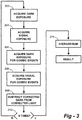
- Figure 1 illustrates current standard practice involving a single stored dark spectrum.
- a collection cycle consists of N accumulations of single exposures, each within the dynamic range of the array detector, summed or averaged to achieve a target SNR for the most difficult (typically the weakest) spectral feature in application. The resulting sum or average will henceforth be referred to as a spectrum.
- a dark exposure is acquired with signal light blocked, thus acquiring one dark exposure at 102.
- a second dark exposure is acquired at 104 for cosmic event correction, and this process is repeated by summing or averaging the cosmic corrected exposures at 108 for N accumulations (106).
- “cosmic correction” should be taken to mean combining two (or more) exposures in such a way as to eliminate pixel signal if one of the exposures show evidence of cosmic ray spikes, while averaging the pixels from the both exposures if neither has a cosmic-ray-induced spike.
- “N” is typically determined by the ratio of the strongest feature in the spectrum to the weakest feature, such that each of the N accumulations is sufficiently short to avoid detector saturation at the strongest feature, and the total exposure time T over N accumulations provides the required SNR for the weakest component.
- the resulting dark spectrum is saved at 110 and subtracted at 112 from all subsequent signal collection spectra acquired in the same manner, but with signal light illuminating the detectors.
- the result is output at 114.
- This approach may comprise a standard practice for sufficiently stable dark current, which can be the case for very stable dark current, typically characterized by very stable thermal environments for both detector and spectrograph hardware. It can also be the case for applications with very strong signals relative to dark current.
- the cycle time for data within a run is the shortest possible because once the single dark spectrum is acquired, signal data is being acquired at all times. Total data reporting cycle time for the method of Figure 1 is T, as dictated by the weakest component of interest.
- Figure 2 illustrates an alternative standard practice involving interleaved dark spectra.
- a dark spectrum is acquired at 202, followed by the acquisition of signal spectra at 204.
- the dark signal is subtracted from the light spectrum at 206.
- a new dark spectrum is acquired over N accumulations as described above in between each signal cycle of N accumulations. This allows the instrument to correct for changes in dark current over the course of a data run. However, it doubles the data cycle time relative to Standard Practice 1, because half of the time is spent acquiring dark spectra, not signal. Thus, total data reporting cycle time is 2T.
- Bowie disclose a dark current correction in a Raman spectrometer by collecting a set of dark exposures and signal exposures. The dark exposure scans are subtracted from the signal exposure scans.
- US 4,357,673 discloses a spectrophotometer which performs measurements and calculates the average and the variance of the measurements.
- the spectrophotometer measures sets of dark, reference and sample spectra for use in calculating an average absorbance spectrum and its variance.
- the disclosure is directed to a system and method of dark current correction in a spectrometer having a detector adapted to receive light from a sample.
- the overall goal is to provide for efficient dark correction while keeping the total data collection cycle to a minimum.
- the various embodiments also enable more rapid reporting of data than that which would normally be dictated by accurate quantitation of the weakest signal of interest.
- the disclosure affords better matching of dark subtraction to the true dark when light data is acquired. This results in more stable baselines, especially towards the edges where intensity correction magnifies any non-zero results of dark subtraction, and changes in dark current due to changes in temperature of the camera window frame are typically more pronounced. The resulting induced curvature of the baseline makes quantitation difficult in these regions.
- One disclosed method allows dark data to be pre-calibrated during extended periods of time to improve the accuracy and reduce noise, then these calibrations can be used at any point in the future without incurring an increased measurement time.
- Alternative methods provide additional metrics for the identification of system failure states such as loss of camera vacuum seal, drift in the temperature stabilization, and light leaks.
- a processor receives signals from a light detector in the spectrometer and executes software programs to calculate spectral responses, sum or average results, and perform other operations necessary to carry out the disclosed methods.
- the light signals received from a sample are used for Raman analysis.
- a collection cycle comprises dark exposure 302, light exposure 304, repeat dark for cosmic correction check 306, repeat light for cosmic correction check 308, and generate one accumulation by subtracting the cosmic-corrected dark exposure from the cosmic-corrected light exposure (310). These steps are repeated N times through decision block 312 for each accumulation. At 314 the accumulations are summed or averaged to build up the target SNR for the application.
- the acquisition cycle includes performing Interleaved Dark Exposures of Figure 3 for each accumulation, storing each of the N accumulations in a buffer.
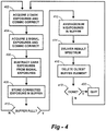
- Two dark exposures are collected and cosmically corrected at 402; two light exposures are collected and cosmically corrected at 404; with the difference 406 being stored in a buffer at 408.
- a sum or average is taken at 412 a first collect cycle spectrum result is returned at 414, and the oldest buffer element is deleted.
- Steps 402-408 are repeated through 416, and the result of each corrected exposure is added to the buffer as newest buffer element.
- Another collect cycle spectrum is returned which incorporates all buffer elements including the newest one.
- a dark is collected at the beginning of an experiment at 502 using the entire data collection cycle and stored as in Standard Practice 1.
- This dark uses the same region of the camera as light collection, but with no light entering the camera, and will be referred to as the true dark (TD).
- TD true dark
- a second dark is collected at 504 using regions of the camera not normally illuminated during signal collection, such as in between signal fiber images on a 2-dimensional CCD array, or non-illuminated regions of a linear array detector.
- This dark is collected with light entering the camera and will be referred to as the unilluminated dark (UD).
- TD fn (UD). In some situations the functions may simply be a multiplication by constant.
- a light collection cycle is then started at 508. Simultaneously, another UD is collected at 510 using detector regions not illuminated by signal light. Using the previously developed relationship between the TD and the UD, a new TD is calculated at 512 using the monitored UD signal. The calculated TD is then subtracted from the signal exposure at 514. The result at 516 should closely match the signal corrected by true dark during light collection. No additional exposure time is required.
- T Data reporting cycle time after initial dark collection is T, which is equivalent to Standard Practice 1. Drifting dark current is now corrected, although not as accurately as with the Rolling Collection approach. If the dark current drift is reasonably consistent across the detector array, this can provide sufficiently accurate correction. A new relationship between the TD and the UD is developed each time the experimental parameters (such as time of exposure or detector temperature) change. No additional inputs to the function relating TD and UD are necessary other than the UD.
- the initial dark may be taken for a subset of total accumulations to save start-up time, but this would compromise SNR.
- the UD does not have to be a contiguous stripe across the camera but can in fact be any collection of unilluminated pixels.
- the approach of Figure 6 essentially combines the improved Methods 2 and 3 ( Figures 4 and 5 ).
- the technique represents a rolling collection of both signal and dynamically modeled TD correction, reporting data on every signal accumulation without interleaved dark collections.
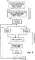
- Blocks 602, 604 and 606 are equivalent to the initialization cycle of Figure 5 , and blocks 608, 610, 612 representing the collection cycle.
- the dark is subtracted from the signal and the result being stored in a buffer at 616.
- a sum or average is taken at 620, a first collect cycle spectrum result is returned at 622, and the oldest buffer element is deleted at 624.
- Steps 608-624 are repeated through 626, and the result of each accumulation is added to the buffer as newest buffer element.
- Another collect cycle spectrum is returned which incorporates all buffer elements including the newest one.
- the data reporting cycle time is T/N, which is twice the speed of Rolling Collection Method 2.
- the complete dark spectrum response to relevant parameters can be measured over the entire array and stored once in advance at select intervals within the expected operational ranges. These parameters can then be measured during operation, and the expected operational dark signal calculated via interpolation of the stored data. This provides the advantage of low noise dark current subtraction, with the operational simplicity of Standard Practice 1, although a new static model would have to be developed for each instrument at the time of manufacture or refurbishment.
- the technique is diagrammed in Figure 7 .
- dark response is measured at various detector states.
- dark response is measured in conjunction with various detector parameters such as different temperatures, exposure time(s), and so forth.
- the responses acquired at 702, 704 are stored at 706 as a specific model for that particular detector.
- the collection cycle begins at 710, wherein the signal spectrum is collected along with the state and parametric information derived at 702, 704. This allows the dark spectrum to be calculated using the stored model at 712. The calculated dark is subtracted from the signal at 714 and this is repeated N times via 716. The corrected signal exposures are summed or averaged at 718 and the result delivered at 720.
- Data reporting cycle time can be either T or T/N, depending on the incorporation of the rolling average method described in Method 4.
- the not-claimed embodiment shown in Figure 8 represents a combination of Methods 3 and 5.
- a functional relationship is developed at 806 between true dark (TD) and relevant operational parameters (e.g., integration time, array temperature).
- another functional relationship is developed at 810 between unilluminated dark at 808 (where light is entering the camera but not falling on the UD regions) and the operational parameters used in the first functional relationship. This will be referred to as statically modeled unilluminated dark (SMUD).
- SMUD statically modeled unilluminated dark
- the statically modeled dark correction is supplemented with a scaled dark correction factor determined from the difference between the actual UD that is measured and the UD that is predicted from the statically modeled unilluminated dark.
- This process includes statistical measures to determine when the UD region differs significantly from the calculated UD value, in turn triggering the application of an additional scaled dark correction to supplement the statically modeled dark function.
- This approach can also provide additional benefits, such as correcting for interchannel smearing in shutter-free applications and handling unexpected light leakage inside the spectrograph.
- Data reporting cycle time can be either T or T/N depending on the incorporation of the rolling average method described in Method 4.
- the total number of accumulations N is typically related to the ratio of the strongest signal to the weakest signal in the spectrum in order to avoid detector saturation on any single accumulation.
- Improved methods 2 and 4 shorten the data reporting cycle to 2T/N or T/N respectively.
- Some applications may need still faster reporting cycles to support control system requirements.
- An example of such an application would be optimizing the efficiency of a natural gas turbine power generator based on the varying concentrations of different hydrocarbon constituents in the gas being fed to the generator.
- the required signal exposure time T may be divided in to a larger number of accumulations N in order to report at a speed consistent with the control application.
- the number N will be limited at some point by increasing relative significance of detector read noise and A/D quantization noise, as understood to those of skill in the art.
- Improved methods 2 and 4 above provide more rapid indications of an onset changes in sample constituents than standard practice. However, they still nominally require time 2T or T, respectively, to fully respond to a step change in the sample.
- Methods 2 and 4 may be further modified such that the stronger spectral components are assigned buffer sizes that are smaller than the N accumulations as described in Method 2. As described above, T is dictated by the weakest component in the spectrum, whereas stronger constituents can achieve a target SNR in a shorter total exposure time.
- the buffer size By customizing the buffer size to be smaller than N as appropriate for stronger spectrum components, detector-by-detector, the system can be made to fully respond to changes in concentration on stronger components more rapidly.
- Additional advantages may be gained by acquiring multiple dark and multiple signal exposures, but splitting the dark collections so that half are taken before the signal exposures, and half are taken after the signal exposures. The total dark is then subtracted from the signal to produce a "collection.”
- This method has two advantages. First, by splitting the darks into two halves that bracket the signal, the dark spectrum better matches the true dark contribution to the bracketed signal collection.
- a second advantage is that the ending dark half-series of one collection is re-used as the beginning half-series of darks for the following collection, thus saving time. For equivalent total number of darks to signal exposures, the data cycle time drops from 2T to 1.5T, as shown conceptually in Figure 9 .
- each time interval of dark and signal integration may be a summation or average of multiple camera exposures/readouts. This is often necessary in order to acquire a target Signal to Noise Ratio (SNR) on spectral features that might otherwise be too weak, as limited by the dynamic range of the camera, the dark current of the camera, and/or stronger signals in the spectrum.
- SNR Signal to Noise Ratio
- Cosmic filtering may be applied to each exposure of dark and signal.
- the disclosed method splits a desired exposure interval into two equal sub-intervals.
- the two sub-intervals are compared with each other to detect any anomalous high-intensity "spikes" in one of the two spectra. These spikes occur due to random, low-probability cosmic radiation events and are discarded when detected. Any reference to an "exposure” below may also in practice be cosmically filtered data acquired in this way.
- the number of dark exposures does not necessarily have to match the number of signal exposures if the noise inherent in the dark exposure is not a substantial contributor to the total noise inherent in the collection. Such would be the case in a scenario where the dark current is much lower than the signal current. In such a scenario, additional time gains can be made by using less total dark exposures than signal exposures, providing signal to noise of the resulting collection is still adequate. In such a case, the shorter dark exposures can be scaled to compensate for the different total integration time relative to the signal exposures, yielding an effective integration time of T/2 according to Figure 9 .
- the bracketed dark method is applicable to any embodiment disclosed herein where multiple dark and signal collections are performed in order to achieve a desired signal-to-noise ratio. Indeed, this modification is applicable to the Standard Practice of Figure 2 .
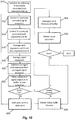
- the improvement of the bracketed dark method is also applicable to the embodiments that employ a buffer. By defining a "collection" as one corrected averaged/summed signal exposure, each collection is placed in a buffer which can then be used to return averaged or summed collections as a spectrum on a rolling basis (i.e., a FIFO buffer). To demonstrate, the modification is applied to Method 2, the "Rolling Collection" method shown in Figure 4 , with the modified version being depicted in Figure 10 . As will be appreciated by one skilled in the art having the benefit of the present disclosure, the bracketed dark method may be applied to each of the embodiments disclosed herein. A detailed description of the bracketed dark method according to Figure 10 is as follows:
- Interleaved dark collection as described herein is the most accurate way to track dark current, particularly for single row cameras with high and significantly varying dark current such as an InGaAs linear array camera, and also the most accurate way for a 2D array camera such as a CCD, providing both increased data reporting rate at target SNR, and most accurate correction for varying dark current.
- the Standard Practice of a single dark collection may be faster in certain applications, providing twice the data/response rate in return for a less rigorous estimated tracking of dark current.
- the Dynamically Modeled Dark correction is the fastest overall method (including manufacturing time and end-user time), as it requires no additional effort at time of manufacture.
- the Dynamically Modeled Dark method provides still faster reporting of data from the viewpoint of the customer, although in certain applications additional specific model must be developed at time of manufacture.
- the Bracketed Dark methods reduce collection times while improving accuracy of the dark spectrum.
- several of the methods described herein can benefit by implementation as a rolling average, if demanded by a process control system, without actually changing the amount of time for the system to fully respond to a step change in the process constituents.
- customization of the amount of averaging based on process control requirements or component concentration can also be employed.
- the disclosure may have presented a method and/or process as a particular sequence of steps.
- the method or process should not be limited to the particular sequence of steps described.
- Other sequences of steps may be possible and are therefore contemplated by the inventor. Therefore, the particular order of the steps disclosed herein should not be construed as limitations of the present disclosure.
- disclosure directed to a method and/or process should not be limited to the performance of their steps in the order written.
Landscapes
- Physics & Mathematics (AREA)
- Spectroscopy & Molecular Physics (AREA)
- General Physics & Mathematics (AREA)
- Investigating, Analyzing Materials By Fluorescence Or Luminescence (AREA)
- Spectrometry And Color Measurement (AREA)
Description
- The present application is related to and claims the priority benefit of
U.S. Patent Application Serial Nos. 14/728,818, filed June 2, 2015 14/950,598, filed November 24, 2015 - The present disclosure relates generally to spectrometers and, in particular, to methods for collection, dark correction and reporting from such instruments.
- Electronic light-recording devices such as charge-coupled display (CCD) cameras, single element arrays, as found in InGaAs cameras, and so forth, have a dark response (i.e., a signal in the absence of light) which must be corrected. Normally this involves taking an exposure cycle in the absence of light from the sample to be measured and storing it as a "dark spectrum." Light from the sample is then passed to the camera for an identical exposure cycle to generate an "uncorrected sample spectrum." A "corrected" sample spectrum is then computed by subtracting the dark spectrum from the uncorrected sample spectrum. (Other forms of correction are then computed to correct for the spectral responsivity of the detectors, the spectral mapping of the array, interpolation, etc., but these are separate subjects outside the scope of this disclosure.) As the time between collection of the dark and the collection of light becomes larger, the dark data may not match the true camera response in the absence of light due to temperature fluctuation or other reasons.
- If the dark spectrum is updated prior to each light exposure cycle, this essentially doubles the amount of time required for a total data collection cycle. Further, when analyzing spectra that contain both very weak and very strong spectral components of interest, the exposure cycle time required for adequate SNR (signal-to-noise)/quantitation on the very weak components, such as in analysis of gas mixtures by Raman spectroscopy, can be very long - on the order of several minutes. Stronger components in the same mixture may be accurately quantitated in a matter of seconds.
- Conventional techniques either collect one dark spectrum and apply it to all future spectra in an experiment or monitoring process or collect a new dark spectrum before each signal spectrum. Conventional techniques to solve the dark correction problem either are inefficient in the amount of time required, or inaccurate in matching the true dark response at the time of light collection. Accordingly, there remains a need for further contributions in this area of technology dark correction under changing conditions.
-
Figure 1 illustrates current standard practice involving a single stored dark spectrum. A collection cycle consists of N accumulations of single exposures, each within the dynamic range of the array detector, summed or averaged to achieve a target SNR for the most difficult (typically the weakest) spectral feature in application. The resulting sum or average will henceforth be referred to as a spectrum. A dark exposure is acquired with signal light blocked, thus acquiring one dark exposure at 102. A second dark exposure is acquired at 104 for cosmic event correction, and this process is repeated by summing or averaging the cosmic corrected exposures at 108 for N accumulations (106). In accordance with this disclosure, including the embodiments described here, "cosmic correction" should be taken to mean combining two (or more) exposures in such a way as to eliminate pixel signal if one of the exposures show evidence of cosmic ray spikes, while averaging the pixels from the both exposures if neither has a cosmic-ray-induced spike. Further, "N" is typically determined by the ratio of the strongest feature in the spectrum to the weakest feature, such that each of the N accumulations is sufficiently short to avoid detector saturation at the strongest feature, and the total exposure time T over N accumulations provides the required SNR for the weakest component. - The resulting dark spectrum is saved at 110 and subtracted at 112 from all subsequent signal collection spectra acquired in the same manner, but with signal light illuminating the detectors. The result is output at 114. This approach may comprise a standard practice for sufficiently stable dark current, which can be the case for very stable dark current, typically characterized by very stable thermal environments for both detector and spectrograph hardware. It can also be the case for applications with very strong signals relative to dark current. The cycle time for data within a run is the shortest possible because once the single dark spectrum is acquired, signal data is being acquired at all times. Total data reporting cycle time for the method of
Figure 1 is T, as dictated by the weakest component of interest. -
Figure 2 illustrates an alternative standard practice involving interleaved dark spectra. A dark spectrum is acquired at 202, followed by the acquisition of signal spectra at 204. The dark signal is subtracted from the light spectrum at 206. A new dark spectrum is acquired over N accumulations as described above in between each signal cycle of N accumulations. This allows the instrument to correct for changes in dark current over the course of a data run. However, it doubles the data cycle time relative to Standard Practice 1, because half of the time is spent acquiring dark spectra, not signal. Thus, total data reporting cycle time is 2T. - BOWIE B T ET AL published a paper called "FACTORS AFFECTING THE PERFORMANCE OF BENCH-TOP RAMAN SPECTROMETERS. PART I: INSTRUMENTAL EFFECTS" in APPLIED SPECTROSCOPY, THE SOCIETY FOR APPLIED SPECTROSCOPY. BALTIMORE, US, (20000501), vol. 54, no. 5, doi:10.1366/0003702001949924, ISSN 0003-7028, pages 164A - 173A. Bowie disclose a dark current correction in a Raman spectrometer by collecting a set of dark exposures and signal exposures. The dark exposure scans are subtracted from the signal exposure scans.
-
US 4,357,673 discloses a spectrophotometer which performs measurements and calculates the average and the variance of the measurements. The spectrophotometer measures sets of dark, reference and sample spectra for use in calculating an average absorbance spectrum and its variance. - The disclosure is directed to a system and method of dark current correction in a spectrometer having a detector adapted to receive light from a sample. The overall goal is to provide for efficient dark correction while keeping the total data collection cycle to a minimum. The various embodiments also enable more rapid reporting of data than that which would normally be dictated by accurate quantitation of the weakest signal of interest.
- The disclosure affords better matching of dark subtraction to the true dark when light data is acquired. This results in more stable baselines, especially towards the edges where intensity correction magnifies any non-zero results of dark subtraction, and changes in dark current due to changes in temperature of the camera window frame are typically more pronounced. The resulting induced curvature of the baseline makes quantitation difficult in these regions.
- One disclosed method allows dark data to be pre-calibrated during extended periods of time to improve the accuracy and reduce noise, then these calibrations can be used at any point in the future without incurring an increased measurement time. Alternative methods provide additional metrics for the identification of system failure states such as loss of camera vacuum seal, drift in the temperature stabilization, and light leaks.
- In system aspects of the disclosure, a processor receives signals from a light detector in the spectrometer and executes software programs to calculate spectral responses, sum or average results, and perform other operations necessary to carry out the disclosed methods. In most preferred embodiments, the light signals received from a sample are used for Raman analysis.
-
-
FIGURE 1 is a diagram that illustrates a current standard practice involving a single stored dark spectrum; -
FIGURE 2 illustrates an alternative standard practice involving interleaved dark spectra; -
FIGURE 3 illustrates an interleaved dark exposure method; -
FIGURE 4 illustrates a rolling collection method; -
FIGURE 5 illustrates a scaled dark collection method; -
FIGURE 6 illustrates an embodiment of the invention that combines the Methods depicted inFigures 4 and5 ; -
FIGURE 7 illustrates a calculated full spectrum dark; -
FIGURE 8 illustrates an embodiment that combines the Methods depicted inFigures 5 and7 ; -
FIGURE 9 is a simplified flow diagram that depicts a bracketed dark method; and -
FIGURE 10 is a detailed flow diagram of a bracketed dark method. - In accordance with this embodiment, but not part of the claimed invention, diagrammed in
Figure 3 , a collection cycle comprisesdark exposure 302,light exposure 304, repeat dark forcosmic correction check 306, repeat light forcosmic correction check 308, and generate one accumulation by subtracting the cosmic-corrected dark exposure from the cosmic-corrected light exposure (310). These steps are repeated N times throughdecision block 312 for each accumulation. At 314 the accumulations are summed or averaged to build up the target SNR for the application. - This improvement doubles the fastest possible cycle time and better matches the true dark for light collection periods to the stored dark as compared to
Standard Practice 2. This can be significant in applications where dark current can drift significantly within a long single data cycle of N accumulations. Data reporting cycle time is 2T, equivalent toStandard Practice 2, but provides more accurate tracking of dark current drift thanStandard Practice 2. - In the not claimed embodiment of
Figure 4 , the acquisition cycle includes performing Interleaved Dark Exposures ofFigure 3 for each accumulation, storing each of the N accumulations in a buffer. Two dark exposures are collected and cosmically corrected at 402; two light exposures are collected and cosmically corrected at 404; with thedifference 406 being stored in a buffer at 408. When desired number of exposures N has occurred (at 410), a sum or average is taken at 412 a first collect cycle spectrum result is returned at 414, and the oldest buffer element is deleted. Steps 402-408 are repeated through 416, and the result of each corrected exposure is added to the buffer as newest buffer element. Another collect cycle spectrum is returned which incorporates all buffer elements including the newest one. - This process is repeated as a rolling sum or average spectrum delivery until a sufficient number of spectra has been achieved via
block 418, in which case the process quits at 420. Although full reaction to a step change in signal level is similar toStandard practice 2, data reporting to indicate the onset of a signal change is actually faster than the cycle time of Standard Practice 1, returning a new spectrum with the target SNR on every accumulation, instead of every N accumulations. The data reporting cycle time is now 2T/N (except for the first spectrum which would be delivered after 2T). - In accordance with the not-claimed embodiment of
Figure 5 , a dark is collected at the beginning of an experiment at 502 using the entire data collection cycle and stored as in Standard Practice 1. This dark uses the same region of the camera as light collection, but with no light entering the camera, and will be referred to as the true dark (TD). Subsequently, a second dark is collected at 504 using regions of the camera not normally illuminated during signal collection, such as in between signal fiber images on a 2-dimensional CCD array, or non-illuminated regions of a linear array detector. This dark is collected with light entering the camera and will be referred to as the unilluminated dark (UD). - At 506, a relationship is developed dynamically between the TD and UD, indicated as TD = fn(UD). In some situations the functions may simply be a multiplication by constant. A light collection cycle is then started at 508. Simultaneously, another UD is collected at 510 using detector regions not illuminated by signal light. Using the previously developed relationship between the TD and the UD, a new TD is calculated at 512 using the monitored UD signal. The calculated TD is then subtracted from the signal exposure at 514. The result at 516 should closely match the signal corrected by true dark during light collection. No additional exposure time is required.
- Data reporting cycle time after initial dark collection is T, which is equivalent to Standard Practice 1. Drifting dark current is now corrected, although not as accurately as with the Rolling Collection approach. If the dark current drift is reasonably consistent across the detector array, this can provide sufficiently accurate correction. A new relationship between the TD and the UD is developed each time the experimental parameters (such as time of exposure or detector temperature) change. No additional inputs to the function relating TD and UD are necessary other than the UD.
- Note that in this method, the initial dark may be taken for a subset of total accumulations to save start-up time, but this would compromise SNR. Also, the UD does not have to be a contiguous stripe across the camera but can in fact be any collection of unilluminated pixels.
- The approach of
Figure 6 essentially combines theimproved Methods 2 and 3 (Figures 4 and5 ). The technique represents a rolling collection of both signal and dynamically modeled TD correction, reporting data on every signal accumulation without interleaved dark collections.Blocks Figure 5 , and blocks 608, 610, 612 representing the collection cycle. At 614 the dark is subtracted from the signal and the result being stored in a buffer at 616. As with the process ofFigure 4 , when desired number of accumulations N has occurred (at 618), a sum or average is taken at 620, a first collect cycle spectrum result is returned at 622, and the oldest buffer element is deleted at 624. Steps 608-624 are repeated through 626, and the result of each accumulation is added to the buffer as newest buffer element. Another collect cycle spectrum is returned which incorporates all buffer elements including the newest one. The data reporting cycle time is T/N, which is twice the speed ofRolling Collection Method 2. - For cameras with a consistent dark current vs. detector temperature characteristic, the complete dark spectrum response to relevant parameters, such as integration time and detector array temperature, can be measured over the entire array and stored once in advance at select intervals within the expected operational ranges. These parameters can then be measured during operation, and the expected operational dark signal calculated via interpolation of the stored data. This provides the advantage of low noise dark current subtraction, with the operational simplicity of Standard Practice 1, although a new static model would have to be developed for each instrument at the time of manufacture or refurbishment.
- The technique is diagrammed in
Figure 7 . At 702, dark response is measured at various detector states. At 704, dark response is measured in conjunction with various detector parameters such as different temperatures, exposure time(s), and so forth. The responses acquired at 702, 704 are stored at 706 as a specific model for that particular detector. - The collection cycle begins at 710, wherein the signal spectrum is collected along with the state and parametric information derived at 702, 704. This allows the dark spectrum to be calculated using the stored model at 712. The calculated dark is subtracted from the signal at 714 and this is repeated N times via 716. The corrected signal exposures are summed or averaged at 718 and the result delivered at 720. Data reporting cycle time can be either T or T/N, depending on the incorporation of the rolling average method described in Method 4.
- The not-claimed embodiment shown in
Figure 8 represents a combination of Methods 3 and 5. As in Method 5, a functional relationship is developed at 806 between true dark (TD) and relevant operational parameters (e.g., integration time, array temperature). In addition, another functional relationship is developed at 810 between unilluminated dark at 808 (where light is entering the camera but not falling on the UD regions) and the operational parameters used in the first functional relationship. This will be referred to as statically modeled unilluminated dark (SMUD). As in Method 5, these functional relationships would be developed at the time of instrument manufacture or refurbishment and used for all future correction of exposures where signal light is illuminating the detector regions. - In this embodiment, however, the statically modeled dark correction is supplemented with a scaled dark correction factor determined from the difference between the actual UD that is measured and the UD that is predicted from the statically modeled unilluminated dark. This accounts for camera instability or other operational variables not accounted for in the implementation of Method 5. This process includes statistical measures to determine when the UD region differs significantly from the calculated UD value, in turn triggering the application of an additional scaled dark correction to supplement the statically modeled dark function. This approach can also provide additional benefits, such as correcting for interchannel smearing in shutter-free applications and handling unexpected light leakage inside the spectrograph. Data reporting cycle time can be either T or T/N depending on the incorporation of the rolling average method described in Method 4.
- As described above, the total number of accumulations N is typically related to the ratio of the strongest signal to the weakest signal in the spectrum in order to avoid detector saturation on any single accumulation.
Improved methods 2 and 4 shorten the data reporting cycle to 2T/N or T/N respectively. However, some applications may need still faster reporting cycles to support control system requirements. An example of such an application would be optimizing the efficiency of a natural gas turbine power generator based on the varying concentrations of different hydrocarbon constituents in the gas being fed to the generator. Inimproved methods 2 and 4, the required signal exposure time T may be divided in to a larger number of accumulations N in order to report at a speed consistent with the control application. The number N will be limited at some point by increasing relative significance of detector read noise and A/D quantization noise, as understood to those of skill in the art. -
Improved methods 2 and 4 above provide more rapid indications of an onset changes in sample constituents than standard practice. However, they still nominally require time 2T or T, respectively, to fully respond to a step change in the sample.Methods 2 and 4 may be further modified such that the stronger spectral components are assigned buffer sizes that are smaller than the N accumulations as described inMethod 2. As described above, T is dictated by the weakest component in the spectrum, whereas stronger constituents can achieve a target SNR in a shorter total exposure time. By customizing the buffer size to be smaller than N as appropriate for stronger spectrum components, detector-by-detector, the system can be made to fully respond to changes in concentration on stronger components more rapidly. - Additional advantages may be gained by acquiring multiple dark and multiple signal exposures, but splitting the dark collections so that half are taken before the signal exposures, and half are taken after the signal exposures. The total dark is then subtracted from the signal to produce a "collection." This method has two advantages. First, by splitting the darks into two halves that bracket the signal, the dark spectrum better matches the true dark contribution to the bracketed signal collection. A second advantage is that the ending dark half-series of one collection is re-used as the beginning half-series of darks for the following collection, thus saving time. For equivalent total number of darks to signal exposures, the data cycle time drops from 2T to 1.5T, as shown conceptually in
Figure 9 . - In practice, each time interval of dark and signal integration may be a summation or average of multiple camera exposures/readouts. This is often necessary in order to acquire a target Signal to Noise Ratio (SNR) on spectral features that might otherwise be too weak, as limited by the dynamic range of the camera, the dark current of the camera, and/or stronger signals in the spectrum.
- Cosmic filtering may be applied to each exposure of dark and signal. The disclosed method splits a desired exposure interval into two equal sub-intervals. The two sub-intervals are compared with each other to detect any anomalous high-intensity "spikes" in one of the two spectra. These spikes occur due to random, low-probability cosmic radiation events and are discarded when detected. Any reference to an "exposure" below may also in practice be cosmically filtered data acquired in this way.
- Note that the number of dark exposures does not necessarily have to match the number of signal exposures if the noise inherent in the dark exposure is not a substantial contributor to the total noise inherent in the collection. Such would be the case in a scenario where the dark current is much lower than the signal current. In such a scenario, additional time gains can be made by using less total dark exposures than signal exposures, providing signal to noise of the resulting collection is still adequate. In such a case, the shorter dark exposures can be scaled to compensate for the different total integration time relative to the signal exposures, yielding an effective integration time of T/2 according to
Figure 9 . - The bracketed dark method is applicable to any embodiment disclosed herein where multiple dark and signal collections are performed in order to achieve a desired signal-to-noise ratio. Indeed, this modification is applicable to the Standard Practice of
Figure 2 . The improvement of the bracketed dark method is also applicable to the embodiments that employ a buffer. By defining a "collection" as one corrected averaged/summed signal exposure, each collection is placed in a buffer which can then be used to return averaged or summed collections as a spectrum on a rolling basis (i.e., a FIFO buffer). To demonstrate, the modification is applied toMethod 2, the "Rolling Collection" method shown inFigure 4 , with the modified version being depicted inFigure 10 . As will be appreciated by one skilled in the art having the benefit of the present disclosure, the bracketed dark method may be applied to each of the embodiments disclosed herein. A detailed description of the bracketed dark method according toFigure 10 is as follows: - 1. First a series of D cosmically corrected dark exposures are collected at
step 910, which is referred to herein as set A. - 2. A set of S cosmically corrected signal exposures, where is the sensor shutter is open, are then collected at
step 912. In certain embodiments, D may be ½ S. Alternatively, D may be less, for example, D=1. - 3. A second set of D cosmically corrected dark exposures are collected at
step 914, which is referred to herein as set B. - 4. The two sets of dark exposures (i.e., set A and set B) are then averaged or summed at
step 916. Where summed and where 2D does not equal S, a scaling of the dark sum by multiplying by S/2D may be performed such that the sum is then appropriate for S exposures. - 5. The set of signal exposures are then averaged or summed at
step 918. - 6. The average or sum of the signal exposures is then corrected by subtracting the average or sum of the dark exposures at
step 920. - 7. The subtracted signal exposure, subsequently referred to as one "collection," is stored in a buffer of length N at
step 922. - 8. Steps 912-922 are repeated until the buffer is full. When the buffer is full, the first spectrum is constructed by averaging or summing the N buffer elements at
step 924 and delivered atstep 930. - 9. The oldest element in the buffer is discarded at
step 926. Atstep 928, the previous B set of dark exposures (i.e., previously referred to as set B) is shifted to become a new set A, and the former set A is discarded. - 10. Steps 912-922 are repeated, again filling the buffer. At this point another spectrum can be delivered at
step 930, or the buffer further updated atsteps 926 and/or 928. The update interval (i.e., how many times the buffer is shifted by repeating steps 912-922 andsteps 926 and/or 928) can vary from 1 (i.e., fastest update time; deliver a spectrum after every collection) to N (i.e., slowest update time; no rolling average/sum occurs). - The selection of a method described herein depends on timing, accuracy, setup/computational resource priorities and application requirements. Interleaved dark collection as described herein is the most accurate way to track dark current, particularly for single row cameras with high and significantly varying dark current such as an InGaAs linear array camera, and also the most accurate way for a 2D array camera such as a CCD, providing both increased data reporting rate at target SNR, and most accurate correction for varying dark current. The Standard Practice of a single dark collection may be faster in certain applications, providing twice the data/response rate in return for a less rigorous estimated tracking of dark current. However, the Dynamically Modeled Dark correction is the fastest overall method (including manufacturing time and end-user time), as it requires no additional effort at time of manufacture. The Dynamically Modeled Dark method provides still faster reporting of data from the viewpoint of the customer, although in certain applications additional specific model must be developed at time of manufacture. The Bracketed Dark methods reduce collection times while improving accuracy of the dark spectrum. Finally, several of the methods described herein can benefit by implementation as a rolling average, if demanded by a process control system, without actually changing the amount of time for the system to fully respond to a step change in the process constituents. Lastly, customization of the amount of averaging based on process control requirements or component concentration can also be employed.
- While various embodiments of methods for collection, dark correction, and reporting of spectra from an array detector have been described in considerable detail herein, the embodiments are merely offered by way of non-limiting examples of the disclosure described herein. It will therefore be understood that various changes and modifications may be made, and equivalents may be substituted for elements thereof.
- Further, in describing representative embodiments, the disclosure may have presented a method and/or process as a particular sequence of steps. However, to the extent that the method or process does not rely on the particular order of steps set forth herein, the method or process should not be limited to the particular sequence of steps described. Other sequences of steps may be possible and are therefore contemplated by the inventor. Therefore, the particular order of the steps disclosed herein should not be construed as limitations of the present disclosure. In addition, disclosure directed to a method and/or process should not be limited to the performance of their steps in the order written.
- The invention is defined by the appended claims.
Claims (4)
- A method of dark current correction in an instrument having a detector adapted to receive a light spectrum from a sample with a Raman spectrometer, wherein the light spectrum from the sample includes a Raman spectrum, the method comprising the steps of:(a) initialize by collecting a first set A of dark exposures with an exposure time D (910);(b) collecting a first set of signal exposures with an exposure time S (912);(c) collecting a second set B of dark exposures with an exposure time D, wherein D represents a total exposure time of equal to or less than that of S/2 (914),
thereby splitting the dark exposures to bracket the signal, so that half are taken before the signal exposure (912), and half are taken after the signal exposure (912);(d) averaging or summing A and B, and scaling the result for an equivalent total dark exposure time to the signal exposure time S (916);(e) averaging or summing the signal exposures (918);(f) subtracting the result of (d) from the result of (e) to deliver a dark-corrected collection (920),(g) storing the result of (f) in a first-in/first-out buffer of length N (922);(h) discarding set A and renaming set B as set A if the buffer is not full (928);(i) repeating steps (b) through (g) until the buffer is full, and
re-using the second set B of dark exposures (914) as the beginning half-series of dark exposures for the following collection; and if a spectrum result is desired:(j) averaging or summing the N buffer elements to output the spectrum result (924); and if a spectrum result is not desired:(k) discarding the oldest element in the buffer and returning to step (h) (926). - The method of claim 1, including the step of repeating steps (b) through (f) until a desired signal-to-noise ratio is achieved by summing or averaging the multiple dark-corrected collections from (f).
- The method of claim 1, wherein the spectrum result is delivered after every dark-corrected collection.
- The method of claim 1, wherein the spectrum result is not delivered after every dark-corrected collection.
Applications Claiming Priority (3)
| Application Number | Priority Date | Filing Date | Title |
|---|---|---|---|
| US14/728,818 US20160356646A1 (en) | 2015-06-02 | 2015-06-02 | Methods for collection, dark correction, and reporting of spectra from array detector spectrometers |
| US14/950,598 US10048128B2 (en) | 2015-06-02 | 2015-11-24 | Methods for collection, dark correction, and reporting of spectra from array detector spectrometers |
| PCT/US2016/035413 WO2016196727A2 (en) | 2015-06-02 | 2016-06-02 | Methods for collection, dark correction, and reporting of spectra from array detector spectrometers |
Publications (2)
| Publication Number | Publication Date |
|---|---|
| EP3304015A2 EP3304015A2 (en) | 2018-04-11 |
| EP3304015B1 true EP3304015B1 (en) | 2021-07-28 |
Family
ID=56178454
Family Applications (1)
| Application Number | Title | Priority Date | Filing Date |
|---|---|---|---|
| EP16731415.2A Active EP3304015B1 (en) | 2015-06-02 | 2016-06-02 | Methods for collection, dark correction, and reporting of spectra from array detector spectrometers |
Country Status (4)
| Country | Link |
|---|---|
| US (2) | US10048128B2 (en) |
| EP (1) | EP3304015B1 (en) |
| CN (1) | CN107820563B (en) |
| WO (1) | WO2016196727A2 (en) |
Families Citing this family (21)
| Publication number | Priority date | Publication date | Assignee | Title |
|---|---|---|---|---|
| CN104040309B (en) | 2011-11-03 | 2019-06-07 | 威利食品有限公司 | Inexpensive spectrometric system for end user's food analysis |
| GB2543655B (en) | 2013-08-02 | 2017-11-01 | Verifood Ltd | Compact spectrometer comprising a diffuser, filter matrix, lens array and multiple sensor detector |
| WO2015101992A2 (en) | 2014-01-03 | 2015-07-09 | Verifood, Ltd. | Spectrometry systems, methods, and applications |
| EP3209983A4 (en) | 2014-10-23 | 2018-06-27 | Verifood Ltd. | Accessories for handheld spectrometer |
| WO2016125165A2 (en) | 2015-02-05 | 2016-08-11 | Verifood, Ltd. | Spectrometry system with visible aiming beam |
| WO2016125164A2 (en) | 2015-02-05 | 2016-08-11 | Verifood, Ltd. | Spectrometry system applications |
| WO2016162865A1 (en) | 2015-04-07 | 2016-10-13 | Verifood, Ltd. | Detector for spectrometry system |
| US20160356646A1 (en) * | 2015-06-02 | 2016-12-08 | Kaiser Optical Systems Inc. | Methods for collection, dark correction, and reporting of spectra from array detector spectrometers |
| US10048128B2 (en) * | 2015-06-02 | 2018-08-14 | Kaiser Optical Systems Inc. | Methods for collection, dark correction, and reporting of spectra from array detector spectrometers |
| US10066990B2 (en) | 2015-07-09 | 2018-09-04 | Verifood, Ltd. | Spatially variable filter systems and methods |
| US10203246B2 (en) | 2015-11-20 | 2019-02-12 | Verifood, Ltd. | Systems and methods for calibration of a handheld spectrometer |
| TWI703313B (en) * | 2015-12-09 | 2020-09-01 | 台灣超微光學股份有限公司 | Measuring method of spectrometer, spectrometer and electronic circuitry thereof |
| US10254215B2 (en) | 2016-04-07 | 2019-04-09 | Verifood, Ltd. | Spectrometry system applications |
| EP3488204A4 (en) | 2016-07-20 | 2020-07-22 | Verifood Ltd. | Accessories for handheld spectrometer |
| US10791933B2 (en) | 2016-07-27 | 2020-10-06 | Verifood, Ltd. | Spectrometry systems, methods, and applications |
| GB2572662B (en) * | 2018-10-05 | 2020-06-03 | Res & Innovation Uk | Raman spectrometer |
| CN113167648A (en) | 2018-10-08 | 2021-07-23 | 威利食品有限公司 | Accessory for spectrometer |
| CN110196243B (en) * | 2019-05-17 | 2022-02-11 | 广西科技大学 | Spectrum acquisition method for improving signal-to-noise ratio of Raman spectrum |
| CN110855915B (en) * | 2019-11-29 | 2020-12-08 | 中国科学院长春光学精密机械与物理研究所 | CCD camera response non-uniformity correction method and device for dark current compensation |
| KR102825820B1 (en) * | 2020-12-31 | 2025-06-30 | 삼성전자주식회사 | Performance evaluating method of under display camera |
| CN117053923A (en) * | 2023-08-14 | 2023-11-14 | 上海如海光电科技有限公司 | A dark noise calibration method for spectrometers |
Family Cites Families (14)
| Publication number | Priority date | Publication date | Assignee | Title |
|---|---|---|---|---|
| US4458323A (en) * | 1980-04-18 | 1984-07-03 | Hewlett-Packard Company | Method of performing measurements and error analysis of the measurements |
| US4357673A (en) * | 1980-04-18 | 1982-11-02 | Hewlett-Packard Company | Apparatus for performing measurements and error analysis of the measurements |
| US4891772A (en) * | 1987-04-15 | 1990-01-02 | Cyberoptics Corporation | Point and line range sensors |
| US5544338A (en) * | 1992-12-31 | 1996-08-06 | International Business Machines Corporation | Apparatus and method for raster generation from sparse area array output |
| US5408314A (en) * | 1993-02-24 | 1995-04-18 | Perry; Jeffrey | Dark current subtraction with abbreviated reference cycles and recursive filtering |
| WO2005073682A1 (en) * | 2004-01-30 | 2005-08-11 | Lastek Laboratories Pty Ltd | A method for producing high signal to noise spectral measurements in optical detector arrays |
| US7639291B2 (en) * | 2005-05-27 | 2009-12-29 | Aptina Imaging Corporation | Dark current/channel difference compensated image sensor |
| US8384813B2 (en) * | 2010-12-20 | 2013-02-26 | Omnivision Technologies, Inc. | Suspending column addressing in image sensors |
| JP2013123124A (en) * | 2011-12-09 | 2013-06-20 | Sony Corp | Light detection apparatus and light detection method |
| JP5991775B2 (en) * | 2013-02-20 | 2016-09-14 | キヤノン株式会社 | Measuring apparatus and image forming apparatus |
| US9546904B2 (en) * | 2013-03-15 | 2017-01-17 | P & P Optica Inc. | Apparatus and method for optimizing data capture and data correction for spectroscopic analysis |
| CN104101430B (en) * | 2014-07-08 | 2016-04-13 | 中国科学院光电研究院 | A kind ofly push away the quick absolute radiation calibration method of sweeping color dispersion-type imaging spectrometer |
| US20160356646A1 (en) * | 2015-06-02 | 2016-12-08 | Kaiser Optical Systems Inc. | Methods for collection, dark correction, and reporting of spectra from array detector spectrometers |
| US10048128B2 (en) * | 2015-06-02 | 2018-08-14 | Kaiser Optical Systems Inc. | Methods for collection, dark correction, and reporting of spectra from array detector spectrometers |
-
2015
- 2015-11-24 US US14/950,598 patent/US10048128B2/en active Active
-
2016
- 2016-06-02 CN CN201680031806.4A patent/CN107820563B/en active Active
- 2016-06-02 EP EP16731415.2A patent/EP3304015B1/en active Active
- 2016-06-02 WO PCT/US2016/035413 patent/WO2016196727A2/en not_active Ceased
-
2018
- 2018-07-24 US US16/043,652 patent/US20180328785A1/en not_active Abandoned
Non-Patent Citations (1)
| Title |
|---|
| None * |
Also Published As
| Publication number | Publication date |
|---|---|
| WO2016196727A3 (en) | 2017-01-12 |
| US20180328785A1 (en) | 2018-11-15 |
| US20160356647A1 (en) | 2016-12-08 |
| CN107820563B (en) | 2021-07-20 |
| WO2016196727A2 (en) | 2016-12-08 |
| CN107820563A (en) | 2018-03-20 |
| US10048128B2 (en) | 2018-08-14 |
| EP3304015A2 (en) | 2018-04-11 |
Similar Documents
| Publication | Publication Date | Title |
|---|---|---|
| US10048128B2 (en) | Methods for collection, dark correction, and reporting of spectra from array detector spectrometers | |
| US10260942B2 (en) | Methods for collection, dark correction, and reporting of spectra from array detector spectrometer | |
| Zechmeister et al. | The planet search programme at the ESO CES and HARPS-IV. The search for Jupiter analogues around solar-like stars | |
| KR101110471B1 (en) | Positron ct apparatus | |
| EP2773949B1 (en) | Multiply-sampled cmos sensor for x-ray diffraction measurements with corrections for non-ideal sensor behavior | |
| EP3336522B1 (en) | Analysis apparatus, non-transitory computer readable medium for analysis apparatus, and analysis method | |
| US20080204578A1 (en) | Image sensor dark correction method, apparatus, and system | |
| CN104849360B (en) | System for monitoring chromatographic mode of operation | |
| US7230741B2 (en) | Optimum non-uniformity correction for imaging sensors | |
| Giovinazzo et al. | GET electronics samples data analysis | |
| TWI732264B (en) | Cavity ring-down spectroscopy having interleaved data acquisition for interference mitigation | |
| US20100296627A1 (en) | Imaging apparatus, control method thereof, and program | |
| US10070076B2 (en) | Drift correction method for infrared imaging device | |
| JP5362444B2 (en) | X-ray diagnostic imaging equipment | |
| CN110108694B (en) | Raman Spectrometer Wavenumber Shift Measurement Accuracy Improvement Method | |
| JP7685998B2 (en) | Compensation for polarization effects in photon-counting detectors. | |
| JP7460646B2 (en) | Background generation for FTIR spectroscopy | |
| CN109655415B (en) | Wavelength offset correction method and device and computer equipment | |
| CN108180903B (en) | A Method for Determining Stable State of Space Objects' Attitude Based on Information Entropy | |
| Christou et al. | Image selection and binning for improved atmospheric calibration of infrared speckle data | |
| CN115856993B (en) | Dynamic gain compensation method of silicon photomultiplier | |
| Shenoy et al. | Pixel-Based Non-Linearity Correction for the WFC3 IR Detector | |
| CN119126193B (en) | Performance monitoring and evaluation methods for hard X-ray imagers of advanced space-based solar observatories | |
| KR102942413B1 (en) | Residual gas analysis method, device and system | |
| JPH11337525A (en) | Gas analysis system |
Legal Events
| Date | Code | Title | Description |
|---|---|---|---|
| STAA | Information on the status of an ep patent application or granted ep patent |
Free format text: STATUS: THE INTERNATIONAL PUBLICATION HAS BEEN MADE |
|
| PUAI | Public reference made under article 153(3) epc to a published international application that has entered the european phase |
Free format text: ORIGINAL CODE: 0009012 |
|
| STAA | Information on the status of an ep patent application or granted ep patent |
Free format text: STATUS: REQUEST FOR EXAMINATION WAS MADE |
|
| 17P | Request for examination filed |
Effective date: 20171030 |
|
| AK | Designated contracting states |
Kind code of ref document: A2 Designated state(s): AL AT BE BG CH CY CZ DE DK EE ES FI FR GB GR HR HU IE IS IT LI LT LU LV MC MK MT NL NO PL PT RO RS SE SI SK SM TR |
|
| AX | Request for extension of the european patent |
Extension state: BA ME |
|
| RIN1 | Information on inventor provided before grant (corrected) |
Inventor name: SLATER, JOSEPH B. Inventor name: TEDESCO, JAMES M. Inventor name: ESMONDE-WHITE, FRANCIS Inventor name: WIEGAND, PATRICK Inventor name: SCHIPPER, DARREN |
|
| DAV | Request for validation of the european patent (deleted) | ||
| DAX | Request for extension of the european patent (deleted) | ||
| STAA | Information on the status of an ep patent application or granted ep patent |
Free format text: STATUS: EXAMINATION IS IN PROGRESS |
|
| 17Q | First examination report despatched |
Effective date: 20190712 |
|
| REG | Reference to a national code |
Ref country code: DE Ref legal event code: R079 Ref document number: 602016061241 Country of ref document: DE Free format text: PREVIOUS MAIN CLASS: G01J0003280000 Ipc: G01N0021270000 |
|
| GRAP | Despatch of communication of intention to grant a patent |
Free format text: ORIGINAL CODE: EPIDOSNIGR1 |
|
| STAA | Information on the status of an ep patent application or granted ep patent |
Free format text: STATUS: GRANT OF PATENT IS INTENDED |
|
| RIC1 | Information provided on ipc code assigned before grant |
Ipc: G01N 21/27 20060101AFI20210217BHEP Ipc: G01N 21/65 20060101ALN20210217BHEP Ipc: G01J 3/44 20060101ALI20210217BHEP Ipc: G01J 3/28 20060101ALI20210217BHEP |
|
| INTG | Intention to grant announced |
Effective date: 20210310 |
|
| GRAS | Grant fee paid |
Free format text: ORIGINAL CODE: EPIDOSNIGR3 |
|
| GRAA | (expected) grant |
Free format text: ORIGINAL CODE: 0009210 |
|
| STAA | Information on the status of an ep patent application or granted ep patent |
Free format text: STATUS: THE PATENT HAS BEEN GRANTED |
|
| AK | Designated contracting states |
Kind code of ref document: B1 Designated state(s): AL AT BE BG CH CY CZ DE DK EE ES FI FR GB GR HR HU IE IS IT LI LT LU LV MC MK MT NL NO PL PT RO RS SE SI SK SM TR |
|
| REG | Reference to a national code |
Ref country code: GB Ref legal event code: FG4D |
|
| REG | Reference to a national code |
Ref country code: CH Ref legal event code: EP |
|
| REG | Reference to a national code |
Ref country code: AT Ref legal event code: REF Ref document number: 1415136 Country of ref document: AT Kind code of ref document: T Effective date: 20210815 |
|
| REG | Reference to a national code |
Ref country code: IE Ref legal event code: FG4D |
|
| REG | Reference to a national code |
Ref country code: DE Ref legal event code: R096 Ref document number: 602016061241 Country of ref document: DE |
|
| REG | Reference to a national code |
Ref country code: LT Ref legal event code: MG9D |
|
| REG | Reference to a national code |
Ref country code: NL Ref legal event code: MP Effective date: 20210728 |
|
| REG | Reference to a national code |
Ref country code: AT Ref legal event code: MK05 Ref document number: 1415136 Country of ref document: AT Kind code of ref document: T Effective date: 20210728 |
|
| PG25 | Lapsed in a contracting state [announced via postgrant information from national office to epo] |
Ref country code: RS Free format text: LAPSE BECAUSE OF FAILURE TO SUBMIT A TRANSLATION OF THE DESCRIPTION OR TO PAY THE FEE WITHIN THE PRESCRIBED TIME-LIMIT Effective date: 20210728 Ref country code: SE Free format text: LAPSE BECAUSE OF FAILURE TO SUBMIT A TRANSLATION OF THE DESCRIPTION OR TO PAY THE FEE WITHIN THE PRESCRIBED TIME-LIMIT Effective date: 20210728 Ref country code: PT Free format text: LAPSE BECAUSE OF FAILURE TO SUBMIT A TRANSLATION OF THE DESCRIPTION OR TO PAY THE FEE WITHIN THE PRESCRIBED TIME-LIMIT Effective date: 20211129 Ref country code: NO Free format text: LAPSE BECAUSE OF FAILURE TO SUBMIT A TRANSLATION OF THE DESCRIPTION OR TO PAY THE FEE WITHIN THE PRESCRIBED TIME-LIMIT Effective date: 20211028 Ref country code: NL Free format text: LAPSE BECAUSE OF FAILURE TO SUBMIT A TRANSLATION OF THE DESCRIPTION OR TO PAY THE FEE WITHIN THE PRESCRIBED TIME-LIMIT Effective date: 20210728 Ref country code: HR Free format text: LAPSE BECAUSE OF FAILURE TO SUBMIT A TRANSLATION OF THE DESCRIPTION OR TO PAY THE FEE WITHIN THE PRESCRIBED TIME-LIMIT Effective date: 20210728 Ref country code: FI Free format text: LAPSE BECAUSE OF FAILURE TO SUBMIT A TRANSLATION OF THE DESCRIPTION OR TO PAY THE FEE WITHIN THE PRESCRIBED TIME-LIMIT Effective date: 20210728 Ref country code: ES Free format text: LAPSE BECAUSE OF FAILURE TO SUBMIT A TRANSLATION OF THE DESCRIPTION OR TO PAY THE FEE WITHIN THE PRESCRIBED TIME-LIMIT Effective date: 20210728 Ref country code: AT Free format text: LAPSE BECAUSE OF FAILURE TO SUBMIT A TRANSLATION OF THE DESCRIPTION OR TO PAY THE FEE WITHIN THE PRESCRIBED TIME-LIMIT Effective date: 20210728 Ref country code: BG Free format text: LAPSE BECAUSE OF FAILURE TO SUBMIT A TRANSLATION OF THE DESCRIPTION OR TO PAY THE FEE WITHIN THE PRESCRIBED TIME-LIMIT Effective date: 20211028 Ref country code: LT Free format text: LAPSE BECAUSE OF FAILURE TO SUBMIT A TRANSLATION OF THE DESCRIPTION OR TO PAY THE FEE WITHIN THE PRESCRIBED TIME-LIMIT Effective date: 20210728 |
|
| PG25 | Lapsed in a contracting state [announced via postgrant information from national office to epo] |
Ref country code: PL Free format text: LAPSE BECAUSE OF FAILURE TO SUBMIT A TRANSLATION OF THE DESCRIPTION OR TO PAY THE FEE WITHIN THE PRESCRIBED TIME-LIMIT Effective date: 20210728 Ref country code: LV Free format text: LAPSE BECAUSE OF FAILURE TO SUBMIT A TRANSLATION OF THE DESCRIPTION OR TO PAY THE FEE WITHIN THE PRESCRIBED TIME-LIMIT Effective date: 20210728 Ref country code: GR Free format text: LAPSE BECAUSE OF FAILURE TO SUBMIT A TRANSLATION OF THE DESCRIPTION OR TO PAY THE FEE WITHIN THE PRESCRIBED TIME-LIMIT Effective date: 20211029 |
|
| PG25 | Lapsed in a contracting state [announced via postgrant information from national office to epo] |
Ref country code: DK Free format text: LAPSE BECAUSE OF FAILURE TO SUBMIT A TRANSLATION OF THE DESCRIPTION OR TO PAY THE FEE WITHIN THE PRESCRIBED TIME-LIMIT Effective date: 20210728 |
|
| REG | Reference to a national code |
Ref country code: DE Ref legal event code: R097 Ref document number: 602016061241 Country of ref document: DE |
|
| PG25 | Lapsed in a contracting state [announced via postgrant information from national office to epo] |
Ref country code: SM Free format text: LAPSE BECAUSE OF FAILURE TO SUBMIT A TRANSLATION OF THE DESCRIPTION OR TO PAY THE FEE WITHIN THE PRESCRIBED TIME-LIMIT Effective date: 20210728 Ref country code: SK Free format text: LAPSE BECAUSE OF FAILURE TO SUBMIT A TRANSLATION OF THE DESCRIPTION OR TO PAY THE FEE WITHIN THE PRESCRIBED TIME-LIMIT Effective date: 20210728 Ref country code: RO Free format text: LAPSE BECAUSE OF FAILURE TO SUBMIT A TRANSLATION OF THE DESCRIPTION OR TO PAY THE FEE WITHIN THE PRESCRIBED TIME-LIMIT Effective date: 20210728 Ref country code: EE Free format text: LAPSE BECAUSE OF FAILURE TO SUBMIT A TRANSLATION OF THE DESCRIPTION OR TO PAY THE FEE WITHIN THE PRESCRIBED TIME-LIMIT Effective date: 20210728 Ref country code: CZ Free format text: LAPSE BECAUSE OF FAILURE TO SUBMIT A TRANSLATION OF THE DESCRIPTION OR TO PAY THE FEE WITHIN THE PRESCRIBED TIME-LIMIT Effective date: 20210728 Ref country code: AL Free format text: LAPSE BECAUSE OF FAILURE TO SUBMIT A TRANSLATION OF THE DESCRIPTION OR TO PAY THE FEE WITHIN THE PRESCRIBED TIME-LIMIT Effective date: 20210728 |
|
| PLBE | No opposition filed within time limit |
Free format text: ORIGINAL CODE: 0009261 |
|
| STAA | Information on the status of an ep patent application or granted ep patent |
Free format text: STATUS: NO OPPOSITION FILED WITHIN TIME LIMIT |
|
| 26N | No opposition filed |
Effective date: 20220429 |
|
| PG25 | Lapsed in a contracting state [announced via postgrant information from national office to epo] |
Ref country code: IT Free format text: LAPSE BECAUSE OF FAILURE TO SUBMIT A TRANSLATION OF THE DESCRIPTION OR TO PAY THE FEE WITHIN THE PRESCRIBED TIME-LIMIT Effective date: 20210728 |
|
| PG25 | Lapsed in a contracting state [announced via postgrant information from national office to epo] |
Ref country code: MC Free format text: LAPSE BECAUSE OF FAILURE TO SUBMIT A TRANSLATION OF THE DESCRIPTION OR TO PAY THE FEE WITHIN THE PRESCRIBED TIME-LIMIT Effective date: 20210728 |
|
| REG | Reference to a national code |
Ref country code: CH Ref legal event code: PL |
|
| REG | Reference to a national code |
Ref country code: BE Ref legal event code: MM Effective date: 20220630 |
|
| GBPC | Gb: european patent ceased through non-payment of renewal fee |
Effective date: 20220602 |
|
| REG | Reference to a national code |
Ref country code: DE Ref legal event code: R081 Ref document number: 602016061241 Country of ref document: DE Owner name: ENDRESS+HAUSER OPTICAL ANALYSIS, INC., ANN ARB, US Free format text: FORMER OWNER: KAISER OPTICAL SYSTEMS INC., ANN ARBOR, MI, US |
|
| PG25 | Lapsed in a contracting state [announced via postgrant information from national office to epo] |
Ref country code: LU Free format text: LAPSE BECAUSE OF NON-PAYMENT OF DUE FEES Effective date: 20220602 Ref country code: LI Free format text: LAPSE BECAUSE OF NON-PAYMENT OF DUE FEES Effective date: 20220630 Ref country code: IE Free format text: LAPSE BECAUSE OF NON-PAYMENT OF DUE FEES Effective date: 20220602 Ref country code: FR Free format text: LAPSE BECAUSE OF NON-PAYMENT OF DUE FEES Effective date: 20220630 Ref country code: CH Free format text: LAPSE BECAUSE OF NON-PAYMENT OF DUE FEES Effective date: 20220630 |
|
| PG25 | Lapsed in a contracting state [announced via postgrant information from national office to epo] |
Ref country code: GB Free format text: LAPSE BECAUSE OF NON-PAYMENT OF DUE FEES Effective date: 20220602 Ref country code: BE Free format text: LAPSE BECAUSE OF NON-PAYMENT OF DUE FEES Effective date: 20220630 |
|
| P01 | Opt-out of the competence of the unified patent court (upc) registered |
Effective date: 20230601 |
|
| PG25 | Lapsed in a contracting state [announced via postgrant information from national office to epo] |
Ref country code: HU Free format text: LAPSE BECAUSE OF FAILURE TO SUBMIT A TRANSLATION OF THE DESCRIPTION OR TO PAY THE FEE WITHIN THE PRESCRIBED TIME-LIMIT; INVALID AB INITIO Effective date: 20160602 |
|
| PG25 | Lapsed in a contracting state [announced via postgrant information from national office to epo] |
Ref country code: MK Free format text: LAPSE BECAUSE OF FAILURE TO SUBMIT A TRANSLATION OF THE DESCRIPTION OR TO PAY THE FEE WITHIN THE PRESCRIBED TIME-LIMIT Effective date: 20210728 Ref country code: CY Free format text: LAPSE BECAUSE OF FAILURE TO SUBMIT A TRANSLATION OF THE DESCRIPTION OR TO PAY THE FEE WITHIN THE PRESCRIBED TIME-LIMIT Effective date: 20210728 |
|
| PG25 | Lapsed in a contracting state [announced via postgrant information from national office to epo] |
Ref country code: TR Free format text: LAPSE BECAUSE OF FAILURE TO SUBMIT A TRANSLATION OF THE DESCRIPTION OR TO PAY THE FEE WITHIN THE PRESCRIBED TIME-LIMIT Effective date: 20210728 |
|
| PG25 | Lapsed in a contracting state [announced via postgrant information from national office to epo] |
Ref country code: MT Free format text: LAPSE BECAUSE OF FAILURE TO SUBMIT A TRANSLATION OF THE DESCRIPTION OR TO PAY THE FEE WITHIN THE PRESCRIBED TIME-LIMIT Effective date: 20210728 |
|
| REG | Reference to a national code |
Ref country code: DE Ref legal event code: R082 Ref document number: 602016061241 Country of ref document: DE Representative=s name: DENNEMEYER & ASSOCIATES RECHTSANWALTSGESELLSCH, DE |
|
| PGFP | Annual fee paid to national office [announced via postgrant information from national office to epo] |
Ref country code: DE Payment date: 20250618 Year of fee payment: 10 |