EP3303718B1 - Moyen d'isolation thermique et d'étanchéité pour une fente de sécurité dans un mur rideau - Google Patents
Moyen d'isolation thermique et d'étanchéité pour une fente de sécurité dans un mur rideau Download PDFInfo
- Publication number
- EP3303718B1 EP3303718B1 EP16727483.6A EP16727483A EP3303718B1 EP 3303718 B1 EP3303718 B1 EP 3303718B1 EP 16727483 A EP16727483 A EP 16727483A EP 3303718 B1 EP3303718 B1 EP 3303718B1
- Authority
- EP
- European Patent Office
- Prior art keywords
- insulation means
- primary
- interior panel
- interior
- supplemental
- Prior art date
- Legal status (The legal status is an assumption and is not a legal conclusion. Google has not performed a legal analysis and makes no representation as to the accuracy of the status listed.)
- Active
Links
- 238000007789 sealing Methods 0.000 title claims description 58
- 238000009413 insulation Methods 0.000 claims description 163
- 230000000153 supplemental effect Effects 0.000 claims description 87
- 239000000463 material Substances 0.000 claims description 47
- 238000010276 construction Methods 0.000 claims description 20
- 239000003063 flame retardant Substances 0.000 claims description 17
- 239000011490 mineral wool Substances 0.000 claims description 17
- 238000000576 coating method Methods 0.000 claims description 14
- 238000009435 building construction Methods 0.000 claims description 12
- 239000011248 coating agent Substances 0.000 claims description 12
- 239000000835 fiber Substances 0.000 claims description 5
- XLYOFNOQVPJJNP-UHFFFAOYSA-N water Substances O XLYOFNOQVPJJNP-UHFFFAOYSA-N 0.000 claims description 5
- 239000007921 spray Substances 0.000 claims description 3
- 238000000034 method Methods 0.000 claims 13
- 229910052751 metal Inorganic materials 0.000 description 5
- 229910052782 aluminium Inorganic materials 0.000 description 4
- XAGFODPZIPBFFR-UHFFFAOYSA-N aluminium Chemical compound [Al] XAGFODPZIPBFFR-UHFFFAOYSA-N 0.000 description 4
- 230000006835 compression Effects 0.000 description 4
- 238000007906 compression Methods 0.000 description 4
- 239000002184 metal Substances 0.000 description 4
- 241000357293 Leptobrama muelleri Species 0.000 description 3
- 238000009434 installation Methods 0.000 description 3
- 239000007769 metal material Substances 0.000 description 3
- 229910000831 Steel Inorganic materials 0.000 description 2
- 238000009432 framing Methods 0.000 description 2
- 239000003562 lightweight material Substances 0.000 description 2
- 239000000779 smoke Substances 0.000 description 2
- 239000010959 steel Substances 0.000 description 2
- 229910001369 Brass Inorganic materials 0.000 description 1
- XUIMIQQOPSSXEZ-UHFFFAOYSA-N Silicon Chemical compound [Si] XUIMIQQOPSSXEZ-UHFFFAOYSA-N 0.000 description 1
- 238000005452 bending Methods 0.000 description 1
- 239000010951 brass Substances 0.000 description 1
- 238000005253 cladding Methods 0.000 description 1
- 239000000567 combustion gas Substances 0.000 description 1
- 230000008602 contraction Effects 0.000 description 1
- 238000001816 cooling Methods 0.000 description 1
- 230000001419 dependent effect Effects 0.000 description 1
- 238000005516 engineering process Methods 0.000 description 1
- 230000009970 fire resistant effect Effects 0.000 description 1
- 238000004079 fireproofing Methods 0.000 description 1
- 239000006261 foam material Substances 0.000 description 1
- 239000011521 glass Substances 0.000 description 1
- 238000010438 heat treatment Methods 0.000 description 1
- 230000008595 infiltration Effects 0.000 description 1
- 238000001764 infiltration Methods 0.000 description 1
- 239000011810 insulating material Substances 0.000 description 1
- 239000012774 insulation material Substances 0.000 description 1
- 239000012528 membrane Substances 0.000 description 1
- 238000012986 modification Methods 0.000 description 1
- 230000004048 modification Effects 0.000 description 1
- 239000000565 sealant Substances 0.000 description 1
- 229910052710 silicon Inorganic materials 0.000 description 1
- 239000010703 silicon Substances 0.000 description 1
- 238000005507 spraying Methods 0.000 description 1
- 230000001502 supplementing effect Effects 0.000 description 1
- 239000011800 void material Substances 0.000 description 1
Images


Classifications
-
- E—FIXED CONSTRUCTIONS
- E04—BUILDING
- E04B—GENERAL BUILDING CONSTRUCTIONS; WALLS, e.g. PARTITIONS; ROOFS; FLOORS; CEILINGS; INSULATION OR OTHER PROTECTION OF BUILDINGS
- E04B1/00—Constructions in general; Structures which are not restricted either to walls, e.g. partitions, or floors or ceilings or roofs
- E04B1/62—Insulation or other protection; Elements or use of specified material therefor
- E04B1/66—Sealings
- E04B1/68—Sealings of joints, e.g. expansion joints
-
- E—FIXED CONSTRUCTIONS
- E04—BUILDING
- E04B—GENERAL BUILDING CONSTRUCTIONS; WALLS, e.g. PARTITIONS; ROOFS; FLOORS; CEILINGS; INSULATION OR OTHER PROTECTION OF BUILDINGS
- E04B2/00—Walls, e.g. partitions, for buildings; Wall construction with regard to insulation; Connections specially adapted to walls
- E04B2/88—Curtain walls
- E04B2/90—Curtain walls comprising panels directly attached to the structure
-
- E—FIXED CONSTRUCTIONS
- E04—BUILDING
- E04B—GENERAL BUILDING CONSTRUCTIONS; WALLS, e.g. PARTITIONS; ROOFS; FLOORS; CEILINGS; INSULATION OR OTHER PROTECTION OF BUILDINGS
- E04B1/00—Constructions in general; Structures which are not restricted either to walls, e.g. partitions, or floors or ceilings or roofs
- E04B1/62—Insulation or other protection; Elements or use of specified material therefor
- E04B1/92—Protection against other undesired influences or dangers
- E04B1/94—Protection against other undesired influences or dangers against fire
- E04B1/946—Protection against smoke or toxic gases
-
- E—FIXED CONSTRUCTIONS
- E04—BUILDING
- E04B—GENERAL BUILDING CONSTRUCTIONS; WALLS, e.g. PARTITIONS; ROOFS; FLOORS; CEILINGS; INSULATION OR OTHER PROTECTION OF BUILDINGS
- E04B1/00—Constructions in general; Structures which are not restricted either to walls, e.g. partitions, or floors or ceilings or roofs
- E04B1/62—Insulation or other protection; Elements or use of specified material therefor
- E04B1/92—Protection against other undesired influences or dangers
- E04B1/94—Protection against other undesired influences or dangers against fire
- E04B1/947—Protection against other undesired influences or dangers against fire by closing openings in walls or the like in the case of fire
-
- E—FIXED CONSTRUCTIONS
- E04—BUILDING
- E04B—GENERAL BUILDING CONSTRUCTIONS; WALLS, e.g. PARTITIONS; ROOFS; FLOORS; CEILINGS; INSULATION OR OTHER PROTECTION OF BUILDINGS
- E04B2/00—Walls, e.g. partitions, for buildings; Wall construction with regard to insulation; Connections specially adapted to walls
- E04B2/88—Curtain walls
- E04B2/96—Curtain walls comprising panels attached to the structure through mullions or transoms
- E04B2/962—Curtain walls comprising panels attached to the structure through mullions or transoms with angles or corners in the curtain wall
-
- E—FIXED CONSTRUCTIONS
- E04—BUILDING
- E04B—GENERAL BUILDING CONSTRUCTIONS; WALLS, e.g. PARTITIONS; ROOFS; FLOORS; CEILINGS; INSULATION OR OTHER PROTECTION OF BUILDINGS
- E04B2/00—Walls, e.g. partitions, for buildings; Wall construction with regard to insulation; Connections specially adapted to walls
- E04B2/88—Curtain walls
- E04B2/96—Curtain walls comprising panels attached to the structure through mullions or transoms
- E04B2/965—Connections of mullions and transoms
-
- E—FIXED CONSTRUCTIONS
- E04—BUILDING
- E04B—GENERAL BUILDING CONSTRUCTIONS; WALLS, e.g. PARTITIONS; ROOFS; FLOORS; CEILINGS; INSULATION OR OTHER PROTECTION OF BUILDINGS
- E04B2/00—Walls, e.g. partitions, for buildings; Wall construction with regard to insulation; Connections specially adapted to walls
- E04B2/88—Curtain walls
- E04B2/96—Curtain walls comprising panels attached to the structure through mullions or transoms
- E04B2/967—Details of the cross-section of the mullions or transoms
-
- E—FIXED CONSTRUCTIONS
- E04—BUILDING
- E04B—GENERAL BUILDING CONSTRUCTIONS; WALLS, e.g. PARTITIONS; ROOFS; FLOORS; CEILINGS; INSULATION OR OTHER PROTECTION OF BUILDINGS
- E04B1/00—Constructions in general; Structures which are not restricted either to walls, e.g. partitions, or floors or ceilings or roofs
- E04B1/62—Insulation or other protection; Elements or use of specified material therefor
- E04B1/74—Heat, sound or noise insulation, absorption, or reflection; Other building methods affording favourable thermal or acoustical conditions, e.g. accumulating of heat within walls
- E04B1/76—Heat, sound or noise insulation, absorption, or reflection; Other building methods affording favourable thermal or acoustical conditions, e.g. accumulating of heat within walls specifically with respect to heat only
- E04B2001/7679—Means preventing cold bridging at the junction of an exterior wall with an interior wall or a floor
Definitions
- the present invention relates to the field of constructions and systems designed to thermally insulate and seal a safing slot area defined between a curtain wall and the individual floors of a building.
- the present invention relates to a thermal insulating and sealing means for use with curtain wall structures which include an interior panel such as a back pan or other similar construction which can be of metal or other material extending across the interior surface of a curtain wall which is common in modular designs.
- the interior panels of a curtain wall are generally made from a metal or insulation material which can easily bend, distort or be otherwise deformed when exposed to strong winds or elevated temperatures, such as intensive sunlight or heat, such as in the event of a fire.
- Bending, distorting or deforming of these interior panels can result in significant problems in attempting to maintain a complete thermal insulation and seal within the safing slots between the outer edges of the floor construction and the exterior curtain wall construction during a storm or fire.
- maintaining of a complete thermal insulation and seal at all time during a fire is important to prevent heat, smoke and flames from spreading from one floor to an adjacent floor.
- Curtain walls are general used and applied in modern building constructions and are the outer covering of said constructions in which the outer walls are non-structural, but merely keep the weather out and the occupants in.
- Curtain walls are usually made of a lightweight material, reducing construction costs. The wall transfers horizontal wind loads that are incident upon it to the main building structure through connections at floors or columns of the building.
- Curtain walls are designed to resist air and water infiltration, sway induced by wind and seismic forces acting on the building, and its own dead load weight forces.
- Curtain walls differ from store-front systems in that they are designed to span multiple floors, and take into consideration design requirements such as thermal expansion and contraction, building sway and movement, water diversion, and thermal efficiency for cost-effective heating, cooling, and lighting in the building.
- a curtain wall structure is defined by an interior wall surface, which includes an interior panel, such as a back pan, extending over the interior surface thereof and at least one floor spatially disposed from the inner wall surface.
- the gap between the floor and the back pan of a curtain wall defines a safing slot, also referred to as perimeter slab edge, extending between the interior wall surface of the interior panel and the outer edge of the floor.
- This safing slot is essential to slow the passage of fire and combustion gases between floors. Therefore, it is of great importance to improve firestopping at the safing slot in order to keep heat, smoke and flames from spreading from one floor to an adjacent floor. It is important to note that the firestop at the perimeter slab edge is considered a continuation of the fire-resistance rating of the floor slab.
- the curtain wall itself, however, is not ordinarily required to have a rating.
- thermal insulating and sealing means for thermally insulation and sealing of a safing slot in a building containing a curtain wall structure.
- thermal insulating and sealing means which can be installed from one side, which maintains the safing insulation between the floors of a residential or commercial building and the exterior curtain wall responsive to various conditions, including fire exposure, and to maximize safing insulation at a minimal cost.
- thermal insulating and sealing means which has no limitation of vertical movement capacities as well as limitation to spandrel height.
- the present disclosure provides a thermal insulating and sealing means for effectively thermally insulating and sealing of a safing slot within a building construction having a wall construction defining an interior wall surface, which includes an interior panel extending over the interior surface thereof and at least one floor spatially disposed from the inner wall surface defining the safing slot extending between the interior wall surface of the interior panel and an outer edge of the floor, comprising a primary insulation means of thermally resistant material positioned in the safing slot, wherein the primary insulation means includes an inner primary end surface positionable in abutment with respect to the outer edge of the floor for sealing thereadjacent, an outer primary end surface positionable in abutment with respect to the interior panel, an upper primary facing surface extending between the inner primary end surface and the outer primary end surface and facing upwardly therebetween, a supplemental insulation means of thermally resistant material attached to the interior panel of a wall at a position immediately above the primary insulation means and in abutment with respect to the upper primary facing surface thereof,
- the present disclosure provides a building construction comprising said thermal insulating and sealing means.
- curtain wall structure in context with the present invention refers to a wall structure which is defined by an interior wall surface, including an interior panel, such as a back pan, extending over the interior surface thereof and at least one floor spatially disposed from the inner wall surface.
- sealing slot in context with the present invention refers to the gap between a floor and a back pan of a curtain wall; it is also referred to as "perimeter slab edge", extending between the interior wall surface of the interior panel, i. e. back pan, and the outer edge of the floor.
- internal panel in context with the present invention refers, in particular, to a back pan, preferably a steel back pan.
- the present invention pertains to a thermal insulating and sealing means for effectively thermally insulating and sealing of a safing slot within a building construction having a wall construction defining an interior wall surface, which includes an interior panel extending over the interior surface thereof and at least one floor spatially disposed from the inner wall surface defining the safing slot extending between the interior wall surface of the interior panel and an outer edge of the floor.
- the present invention pertains to a thermal insulating and sealing means for a curtain wall structure.
- the curtain wall back pan safing insulation means of the present invention is considered for the purpose of facilitating firestopping of a safing slot present in those buildings utilizing curtain wall structures for the exterior cladding thereof which includes interior panels, such as back pans, which are often made of materials that can deform responsive to exposure to heat.
- a curtain wall structure is a type of exterior wall system commonly utilized on buildings wherein the curtain wall itself is a non-bearing wall.
- Such curtain walls generally are of a relatively lightweight material and commonly include brass or metal skins. This type of construction is normally used in high-rise buildings for providing a relatively lightweight and inexpensive overall construction.
- Spandrel panels are included in the curtain wall structure to provide the exterior facing thereof and such panels are commonly made of glass, aluminum, thin sheets of foam material and the like.
- One particular type of unitized wall structure which is often used in modular constructions includes an interior panel comprising a metallic sheet extending across the internal membrane and this metal sheet is referred to as the back pan.
- Such curtain wall systems commonly include vertical framing members comprising boxed aluminum channels referred to as mullions and similarly configured horizontally extending pieces as referred to as transoms.
- transom located or transom configuration at floor level is also known as zero spandrel, i.e., bottom of the transom at the level as top of the concrete floor.
- the interior panels of curtain wall structures can be made of many materials and many of these materials are susceptible to distorting responsive to high heat conditions. Some of these panels are of made from metallic materials but other non-metallic materials can also be used for this internal panel which are also capable of distorting such as insulation and aluminum clad insulation and many other materials.
- the thermal insulating and sealing means according to the present invention is applicable for all types of curtain wall structures.
- the primary insulation means includes an inner primary end surface positionable in abutment with respect to the outer edge of the floor for sealing thereadjacent.
- the primary insulation includes an outer primary end surface positionable in abutment with respect to the interior panel of the curtain wall structure and, preferably, attached to the interior surface of the interior curtain wall panel.
- the primary insulation includes an upper primary facing surface extending between the inner primary end surface and the outer primary end surface thereof and facing upwardly therebetween.
- the primary insulation means comprises a thermally resistant flexible material, preferably a mineral wool material, to facilitate placement thereof into the safing slot adjacent one another.
- the thermally resistant flexible mineral wool material is installed with fibers running parallel to the outer edge of the floor and the interior wall surface of the interior panel. Moreover, it is preferred that a min. 4 in. thick, 4-pcf density, mineral wool batt insulation is employed in the system of the present invention.
- the outer primary end surface of the primary insulation means is preferably initially positioned in abutting contact with and unattached to the interior wall surface of the adjacent interior panel.
- the thermal insulating and sealing means further comprises a supplemental insulation means of thermally resistant material attached to the interior panel of a wall at a position immediately above the primary insulation means and in abutment with respect to the upper primary facing surface thereof.
- the supplemental insulation means comprises a thermally resistant flexible material, preferably a mineral wool material, to facilitate placement thereof into the safing slot adjacent one another.
- the thermally resistant flexible mineral wool material is installed with fibers running parallel to the outer edge of the floor and the interior wall surface of the interior panel.
- the primary insulation means and the supplemental insulation means each comprise a thermally resistant flexible material, preferably a mineral wool material, to facilitate placement thereof into the safing slot adjacent one another.
- the supplemental insulation means is in particular positioned in abutment with the upper primary facing surface of the primary insulation means and is attached to the interior wall surface of the interior panel and extends across the safing slot toward the outer edge of the floor thereadjacent.
- the supplemental insulation means is initially compressed against the upper primary facing surface of the primary insulation means when attached to the interior panel adjacent the upper primary facing surface to facilitate maintaining of abutment therewith responsive to thermal deforming movement of the interior panel.
- the thermal insulating and sealing means further comprises a supplemental attachment means for attaching of the supplemental insulation means with respect to the interior panel positioned thereadjacent.
- the supplemental attachment means comprises at least one supplemental attachment device, such as at least one pin or screw means, and at least one nut or washer means.
- the at least one pin or screw means preferably extend through the supplemental insulation means and is attached to the interior wall surface of the interior panel; and wherein the at least one nut or washer means is secured to the at least one pin or screw means adjacent the supplemental insulation means at a position oppositely disposed from the interior wall surface of the interior panel.
- the pin means may comprise a weld pin means and the nut means may comprise a cap nut means.
- other attachment devices may be used to attach the supplemental means according to the present invention.
- the supplemental insulation means is attached by the supplemental attachment means to the interior panel at a position immediately above the primary insulation means and in abutment with respect to the upper primary facing surface thereof and wherein the supplemental insulation means extends outwardly from the interior panel toward the outer edge of the floor.
- the supplemental insulation means shall extend outwardly from the interior panel toward the outer edge of a floor to a position above the primary insulation means at a position spatially disposed from the outer edge of the floor thereadjacent.
- the supplemental insulation means shall extend from the upper surface of adjacent floor to an intermediate position defined within the safing slot.
- the thermal insulating and sealing means may further comprise an outer fire retardant coating positioned across the primary insulation means and the adjacent portions of the interior wall surface of the interior panel and the floor located thereadjacent.
- the sealing characteristics of the construction shown in the present invention are significantly enhanced by the application of such fire retardant coating.
- outer fire retardant coatings are applied by spraying or other similar means of application.
- Such outer fire retardant coatings are for example firestop joint sprays, preferably based on water, and self-leveling silicon sealants.
- the outer fire retardant coating is a water-based firestop joint spray.
- the outer fire retardant coating has a wet film thickness of at least 1/8 in. Additionally, it is preferable that the outer fire retardant coating overs the top of the thermally resistant flexible mineral wool material overlapping the outer edge of the floor and the interior face of interior wall surface of the interior panel by a min of 1/2 in.
- the outer fire retardant material can be applied across the primary insulation means and the adjacent areas of the interior panel and floor. Alternatively, or additionally, the outer fire retardant material can be applied across the supplemental insulation means and the adjacent areas of the interior panel.
- the supplemental insulation means comprises a band of supplemental insulation extending continuous horizontal and in abutment with respect to the upper primary facing surface of the primary insulation means.
- the band of supplemental insulation extending continuous horizontal and in abutment with respect to the upper primary facing surface of the primary insulation means, i.e., curtain wall cover strip, may be installed before or after the outer fire retardant material is applied, if the band of supplemental insulation is installed before the outer fire retardant material is applied, the band of supplemental insulation should be sprayed as well.
- the band of supplemental insulation may be is fastened to the interior panel or directly to the transom by any fastening means known in the art. However, it is preferred that the band of supplemental insulation is fastened to the steel back pan, resulting in no limitation of vertical movement capacities of the joint system.
- the primary insulation means When installing, the primary insulation means is commonly compressed to varying degrees, but normally it is compressed to approximately 25%. This compression will cause the safing primary insulation means to exert a force outwardly against the curtain wall. The interior panels tend to deform responsive to heat by moving generally outwardly away from the safing slot. Because the primary insulation means is compressed into position, it has the capability to expand outwardly to fill these voids created in the primary insulation means responsive to deforming of the curtain wall. Thus if a curtain wall deforms outwardly by 25% of the lateral dimension of the primary insulation means, then the primary insulation means will be capable of filling that void if it was initially installed with 25% compression.
- the supplemental insulation means can be initially installed some compression thereof against the upper surface of the primary insulation means.
- there is no limitation of vertical movement capacities of the joint system due to the attachment of the supplemental insulation means to the interior panel or to the transom, which in the latter case occurs on face.
- lateral dimension of the supplemental insulation means can be varied significantly to accommodate various configurations of different interior panels and safing slots in order to accommodate and effective thermally insulate and seal any such safing slot, such as for example described below in Figure 2 (transom configuration).
- the thermal insulating and sealing means according to the present invention is preferably for use with a building construction having a wall construction defining an interior wall surface, which includes an interior panel extending over the interior surface thereof and at least one floor spatially disposed from the inner wall surface defining a safing slot extending between the interior wall surface of the interior panel and an outer edge of the floor.
- the building construction comprises a thermal insulating and sealing means for effectively thermally insulating and sealing of the safing slot, wherein the thermal insulating and sealing means comprises:
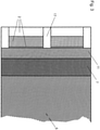
- FIG. 1 a side cross-sectional view of an embodiment of the thermal insulating and sealing means for effectively thermally insulating and sealing of a safing slot 1 within a building construction having a wall construction 2 defining an interior wall surface 3, which includes an interior steel panel 4 extending over the interior surface thereof and at least one floor 5 spatially disposed from the inner wall surface 3 defining the safing slot 1 extending between the interior wall surface 3 of the interior panel 4 and an outer edge 6 of the concrete floor 5.
- the thermal insulating and sealing means comprises a primary insulation means 7 of thermally resistant material, such as thermally resistant flexible mineral wool material, positioned in the safing slot 1.
- the primary insulation means 7 includes an inner primary end surface 8 positioned in abutment with respect to the outer edge 6 of the floor 5 for sealing thereadjacent, an outer primary end surface 9 positioned in abutment with respect to the interior panel 4, an upper primary facing surface 10 extending between the inner primary end surface 8 and the outer primary end surface 9 and facing upwardly therebetween.
- the thermal insulating and sealing means comprises also a supplemental insulation means 11 of thermally resistant material, such as a thermally resistant flexible mineral wool material, attached to the interior panel 4 of a wall at a position immediately above the primary insulation means 7 and in abutment with respect to the upper primary facing surface 10 thereof, and a supplemental attachment means 12 for attaching of the supplemental insulation means 11 with respect to the interior panel 4 positioned thereadjacent.
- thermally resistant flexible mineral wool material is installed with fibers running parallel to the outer edge 6 of the floor 5 and the interior wall surface 3 of the interior panel 4. It is important that insulation is provided between the edge 6 of the floor 5 and the curtain wall 2 in such a manner that the primary insulation means 7 extends from the floor 5 at a position between the upper floor surface 13 and the lower floor surface 14.
- the common placement of primary insulation means 7 is such that the inner primary end surface 8 abuts the outer edge 6 of the floor 5 and extending outwardly such that the outer primary end surface 9 is positioned in full abutting contact with respect to the interior panel 4 of the curtain wall structure 2.
- the band of supplemental insulation 15 extends continuous horizontal and in abutment with respect to the upper primary facing surface 10 of the primary insulation means 7.
- an outer fire retardant coating may be positioned across the primary insulation means 7 and the adjacent portions of the interior wall surface 3 of the interior panel 4 and the floor 5 located thereadjacent in order to further maintain a complete seal extending within the safing slot 1 in those conditions where the interior panel 4 has expanded beyond the lateral expansion capability of the primary insulation means 7.
- the supplemental insulation means 11 is attached to the interior panel 4 preferably by weld pins and cap nuts in such a manner as to be movable along any movement of the interior panel 4 such as when it deforms.
- FIG. 2 is shown a side cross-sectional view of another embodiment of the thermal insulating and sealing means for effectively thermally insulating and sealing of a safing slot 1 within a building construction having a wall construction 2 defining an interior wall surface 3, which includes an interior steel panel 4 extending over the interior surface thereof and at least one floor 5 spatially disposed from the inner wall surface 3 defining the safing slot 1 extending between the interior wall surface 3 of the interior panel 4 and an outer edge 6 of the concrete floor 5.
- the thermal insulating and sealing means comprises a primary insulation means 7 of thermally resistant material, such as thermally resistant flexible mineral wool material, positioned in the safing slot 1.
- the primary insulation means 7 includes an inner primary end surface 8 positioned in abutment with respect to the outer edge 6 of the floor 5 for sealing thereadjacent, an outer primary end surface 9 positioned in abutment with respect to the interior panel 4, an upper primary facing surface 10 extending between the inner primary end surface 8 and the outer primary end surface 9 and facing upwardly therebetween.
- the thermal insulating and sealing means comprises also a supplemental insulation means 11 of thermally resistant material, such as a thermally resistant flexible mineral wool material, attached to the transom 16 of a wall at a position immediately above the primary insulation means 7 and in abutment with respect to the upper primary facing surface 10 thereof, and a supplemental attachment means 12 for attaching of the supplemental insulation means 11 with respect to the interior panel 4 positioned thereadjacent.
- thermally resistant flexible mineral wool material is installed with fibers running parallel to the outer edge 6 of the floor 5 and the interior wall surface 3 of the interior panel 4. It is important that insulation is provided between the edge 6 of the floor 5 and the curtain wall 2 in such a manner that the insulation extends from the floor 5 at a position between the upper floor surface 13 and the lower floor surface 14.
- the common placement of insulation 7 is such that the inner primary end surface 8 abuts the outer edge 6 of the floor 5 and extending outwardly such that the outer primary end surface 9 is positioned in full abutting contact with respect to the interior panel 4 of the curtain wall structure 2.
- the band of supplemental insulation 15 extends continuous horizontal and in abutment with respect to the upper primary facing surface 10 of the primary insulation means 7.
- an outer fire retardant coating may be positioned across the primary insulation means 7 and the adjacent portions of the interior wall surface 3 of the interior panel 4 and the floor 5 located thereadjacent in order to further maintain a complete seal extending within the safing slot 1 in those conditions where the interior panel 4 has expanded beyond the lateral expansion capability of the primary insulation means 7.
- the supplemental insulation means 11 is attached to the transom 16 preferably by weld pins and cap nuts in such a manner as to be movable along any movement of the transom 16 such as when it deforms. Installation of the supplemental insulation means 11 is performed on face on the transom 16 and preferably the lateral height accommodates the height of the transom 16.
- FIG 3 is a top cross-sectional view of the embodiment shown in Figure 1 .
- the vertical framing members comprising boxed aluminum channels are referred to as mullions 17.
- thermal insulating and sealing means for sealing between the edge of a floor and an interior panel of the present invention maintains sealing of the safing slots surrounding the floor of each level in a building despite deforming of the interior panels especially those back pans made of various materials such as metal or the like which are positioned extending across the interior expanse of the curtain walls.
- thermal insulating and sealing means for sealing between the edge of a floor and an interior panel of the present invention provide a means for supplementing the safing insulation surrounding the floors of a building by abutment with the uppersurface thereof by a supplemental belt of insulation which is attached to the interior surface of the interior panel of a modular curtain wall construction.
- thermal insulating and sealing means effectively create a continuous fireproofing seal extending from the outermost edge of the floor to the curtain wall structure and, in particular, to abutment with the interior panel extending across the curtain wall surface.
- thermal insulation and sealing means according to the present invention is easily installable from the top, i.e. a one-sided application.
- mineral wool is stuffed, followed by applying the outer fire resistant coating and installation of the horizontal insulation.
- thermal insulating and sealing means is not limited to a specific joint width or spandrel height; on face installation on the transom is possible and there is no limitation of vertical movement capacities of the joint system, due to the fastening of the band of supplemental insulation to the interior panel.
- thermal insulating and sealing means of the present invention provides a means for effectively maintaining a complete seal in a safing slot when utilizing modular curtain wall constructions which include interior panels extending across the interior surface thereof as is commonly utilized currently for modular or prefabricated designs.
Landscapes
- Engineering & Computer Science (AREA)
- Architecture (AREA)
- Physics & Mathematics (AREA)
- Electromagnetism (AREA)
- Civil Engineering (AREA)
- Structural Engineering (AREA)
- Building Environments (AREA)
Claims (14)
- Procédé permettant efficacement d'isoler thermiquement et d'étanchéifier une fente de sécurité (1) dans une construction de bâtiment ayant une construction de paroi (2) définissant une surface de paroi intérieure (3), qui comporte un panneau intérieur (4) s'étendant sur la surface intérieure de celui-ci et au moins un plancher (5) disposé spatialement à partir de la surface de paroi intérieure (3) définissant la fente de sécurité (1) s'étendant entre la surface de paroi intérieure du panneau intérieur (4) et un bord extérieur (6) du plancher (5), comprenant :i) le positionnement d'un moyen d'isolation primaire (7) en matériau thermiquement résistant dans la fente de sécurité (1), dans lequel le moyen d'isolation primaire (7) comporte :a) une surface d'extrémité principale intérieure (8) pouvant être positionnée en butée par rapport au bord extérieur (6) du plancher (5) pour y assurer l'étanchéité de manière adjacente,b) une surface d'extrémité primaire extérieure (9) positionnée en butée par rapport au panneau intérieur (4), etc) une surface de parement primaire supérieure (10) s'étendant entre la surface d'extrémité primaire intérieure (8) et la surface d'extrémité primaire extérieure (9) et tournée vers le haut entre elles ;ii) le positionnement d'un moyen d'isolation supplémentaire (11) en matériau thermiquement résistant sur le panneau intérieur (4) d'une paroi ;iii) le positionnement d'un moyen de fixation supplémentaire (12) pour fixer le moyen d'isolation supplémentaire (11) par rapport au panneau intérieur (4) positionné de manière adjacente ; etle positionnement d'un revêtement ignifuge extérieur à travers le moyen d'isolation primaire (7) et les parties adjacentes de la surface de paroi intérieure (3) du panneau intérieur (4) et du plancher (6) situé à côté de celui-ci,
caractérisé en ce que le moyen d'isolation supplémentaire (11) est positionné sur le panneau intérieur (4) d'une paroi à une position immédiatement au-dessus du moyen d'isolation primaire (7) et en butée par rapport à la surface de parement primaire supérieure (10) de celui-ci. - Procédé selon la revendication 1, dans lequel le moyen d'isolation primaire (7) et le moyen d'isolation supplémentaire (11) comprennent chacun un matériau flexible thermiquement résistant pour faciliter leur placement dans la fente de sécurité (1) adjacente l'un à l'autre.
- Procédé selon la revendication 1 ou 2, dans lequel le moyen d'isolation primaire (7) et le moyen d'isolation supplémentaire (11) comprennent chacun un matériau en laine minérale flexible thermiquement résistant pour faciliter leur placement dans la fente de sécurité (1) adjacente l'un à l'autre.
- Procédé selon la revendication 3, dans lequel le matériau en laine minérale flexible thermiquement résistant est installé avec des fibres s'étendant parallèlement au bord extérieur (6) du plancher (5) et à la surface de paroi intérieure (3) du panneau intérieur (4).
- Procédé selon l'une quelconque des revendications précédentes, dans lequel la surface d'extrémité primaire extérieure (9) du moyen d'isolation primaire (7) est initialement positionnée en contact de butée avec et non fixée à la surface de paroi intérieure (3) du panneau intérieur adjacent (4).
- Procédé selon l'une quelconque des revendications précédentes, dans lequel le moyen d'isolation supplémentaire (11) est positionné en butée avec la surface de parement primaire supérieure (10) du moyen d'isolation primaire (7) et est fixé à la surface de paroi intérieure (3) du panneau intérieur (4) et s'étend à travers la fente de sécurité (1) vers le bord extérieur (6) du plancher (5) de manière adjacente.
- Procédé selon l'une quelconque des revendications précédentes, dans lequel le moyen de fixation supplémentaire (12) comprend :au moins une broche ou un vis, etau moins un écrou ou une rondelle.
- Procédé selon la revendication 7, dans lequel l'au moins une broche ou un vis s'étend à travers le moyen d'isolation supplémentaire (11) et est fixé(e) à la surface de paroi intérieure (3) du panneau intérieur (4) ; et dans lequel l'au moins un écrou ou une rondelle est fixé(e) à l'au moins une broche ou un vis adjacent(e) au moyen d'isolation supplémentaire (11) à une position disposée à l'opposé de la surface de paroi intérieure (3) du panneau intérieur (4).
- Procédé selon l'une quelconque des revendications précédentes, dans lequel le moyen d'isolation supplémentaire (11) comprend une bande d'isolation supplémentaire (15) s'étendant horizontalement de manière continue et en butée par rapport à la surface de parement primaire supérieure (10) du moyen d'isolation primaire. (7).
- Procédé selon l'une quelconque des revendications précédentes, dans lequel le revêtement ignifuge extérieur est un spray pour joint coupe-feu à base d'eau.
- Procédé selon l'une quelconque des revendications précédentes, dans lequel le moyen d'isolation supplémentaire (11) est fixé au panneau intérieur (4) à une position immédiatement au-dessus du moyen d'isolation primaire (7) et en butée par rapport à la surface de parement primaire supérieure (10) de celui-ci et dans lequel le moyen d'isolation supplémentaire (11) s'étend vers l'extérieur depuis le panneau intérieur (4) vers le bord extérieur (6) du plancher (5).
- Procédé selon la revendication 11, dans lequel le moyen d'isolation supplémentaire (11) s'étend vers l'extérieur depuis le panneau intérieur (4) vers le bord extérieur (6) d'un plancher (5) jusqu'à une position au-dessus du moyen d'isolation primaire (7) à une position spatialement disposée par rapport au bord extérieur (6) du plancher (5) de manière adjacente.
- Procédé selon l'une quelconque des revendications précédentes, dans lequel le moyen d'isolation supplémentaire (11) s'étend depuis la surface supérieure (13) du plancher adjacent (5) jusqu'à une position intermédiaire définie à l'intérieur de la fente de sécurité (1).
- Construction de bâtiment ayant une construction de paroi (2) définissant une surface de paroi intérieure (3), qui comporte un panneau intérieur (4) s'étendant sur sa surface intérieure et au moins un plancher (5) disposé spatialement par rapport à la surface de paroi intérieure (3) définissant une fente de sécurité (1) s'étendant entre la surface de paroi intérieure (3) du panneau intérieur (4) et un bord extérieur (6) du plancher (5), comprenant un moyen d'isolation thermique et d'étanchéité pour efficacement isoler thermiquement et étanchéifier la fente de sécurité (1), dans lequel les moyens d'isolation thermique et d'étanchéité comprennent :i) un moyen d'isolation primaire (7) en matériau thermiquement résistant positionné dans la fente de sécurité (1) définie entre le bord extérieur (6) du plancher (5) et le panneau intérieur (4) pour isoler thermiquement et étanchéifier la fente de sécurité (1), dans lequel le moyen d'isolation primaire (7) comporte :a) une surface d'extrémité principale intérieure (8) pouvant être positionnée en butée par rapport au bord extérieur (6) du plancher (5) pour y assurer l'étanchéité de manière adjacente,b) une surface d'extrémité primaire extérieure (9) pouvant être positionnée en butée par rapport au panneau intérieur (4), etc) une surface de parement primaire supérieure (10) s'étendant entre la surface d'extrémité primaire intérieure (8) et la surface d'extrémité primaire extérieure (9) et tournée vers le haut entre elles ;ii) un moyen d'isolation supplémentaire (11) en matériau thermiquement résistant fixé au panneau intérieur (4) d'une paroi ;iii) un moyen de fixation supplémentaire (12) pour fixer le moyen d'isolation supplémentaire (11) par rapport au panneau intérieur (4) positionné de manière adjacente ; etiv) un revêtement ignifuge extérieur positionné à travers le moyen d'isolation primaire et les parties adjacentes de la surface de paroi intérieure (3) du panneau intérieur (4) et du plancher (6) situé de manière adjacente,dans lequel le moyen de fixation supplémentaire (12) comprend au moins une broche ou un vis s'étendant à travers le moyen d'isolation supplémentaire et étant fixé(e) à la surface de paroi intérieure (3) du panneau intérieur (4), et au moins un écrou ou une rondelle fixé(e) à l'au moins une broche ou un vis adjacent(e) au moyen d'isolation supplémentaire (11) à une position opposée à la surface de paroi intérieure (3) du panneau intérieur (4) pour faciliter la fixation du moyen d'isolation supplémentaire (11) par rapport à la surface de paroi intérieure (3) du panneau intérieur (4) immédiatement au-dessus du moyen d'isolation primaire (7) et en butée par rapport à la surface de parement primaire supérieure (10) de celui-ci, et
dans lequel le moyen d'isolation supplémentaire (11) comprend une bande d'isolation supplémentaire (15) horizontale de manière continue le long et en butée par rapport à la surface de parement primaire supérieure (10) du moyen d'isolation primaire (7),
caractérisé en ce que le moyen d'isolation supplémentaire (11) en matériau thermiquement résistant est fixé au panneau intérieur (4) à une position immédiatement au-dessus du moyen d'isolation primaire (7) et en butée par rapport à la surface de parement primaire supérieure (10) de celui-ci.
Applications Claiming Priority (2)
| Application Number | Priority Date | Filing Date | Title |
|---|---|---|---|
| US14/733,681 US9869086B2 (en) | 2015-06-08 | 2015-06-08 | Thermal insulating and sealing means for a safing slot in a curtain wall |
| PCT/EP2016/062828 WO2016198368A1 (fr) | 2015-06-08 | 2016-06-07 | Moyen d'isolation thermique et d'étanchéité pour une fente de sécurité dans un mur rideau |
Publications (2)
| Publication Number | Publication Date |
|---|---|
| EP3303718A1 EP3303718A1 (fr) | 2018-04-11 |
| EP3303718B1 true EP3303718B1 (fr) | 2022-01-19 |
Family
ID=56108648
Family Applications (1)
| Application Number | Title | Priority Date | Filing Date |
|---|---|---|---|
| EP16727483.6A Active EP3303718B1 (fr) | 2015-06-08 | 2016-06-07 | Moyen d'isolation thermique et d'étanchéité pour une fente de sécurité dans un mur rideau |
Country Status (6)
| Country | Link |
|---|---|
| US (1) | US9869086B2 (fr) |
| EP (1) | EP3303718B1 (fr) |
| AU (1) | AU2016274459B2 (fr) |
| CA (1) | CA2982504C (fr) |
| SG (1) | SG11201708260VA (fr) |
| WO (1) | WO2016198368A1 (fr) |
Families Citing this family (9)
| Publication number | Priority date | Publication date | Assignee | Title |
|---|---|---|---|---|
| EP3056622A1 (fr) * | 2015-02-13 | 2016-08-17 | HILTI Aktiengesellschaft | Bloc façade, construction et procédé de montage du bloc façade |
| CN112411780B (zh) * | 2015-04-17 | 2022-06-28 | 3M创新有限公司 | 耐火建筑物接合系统 |
| US10017939B2 (en) * | 2015-11-24 | 2018-07-10 | Hilti Aktiengesellschaft | Fire-resistance-rated thermally insulating and sealing system for use with curtain wall structures |
| EP3231953A1 (fr) * | 2016-04-13 | 2017-10-18 | HILTI Aktiengesellschaft | Isolation thermique et acoustique et moyen d'étanchéité pour une fente de sécurité dans un mur rideau |
| EP3246481A1 (fr) * | 2016-05-20 | 2017-11-22 | HILTI Aktiengesellschaft | Isolation thermique et acoustique et système d'étanchéité pour une fente de sécurité dans un mur rideau |
| US11713572B2 (en) * | 2017-05-19 | 2023-08-01 | Hilti Aktiengesellschaft | Process for assembling a unitized panel for use within an exterior dynamic curtain wall assembly |
| US10202759B2 (en) * | 2017-05-19 | 2019-02-12 | Hilti Aktiengesellschaft | Dynamic, fire-resistance-rated thermally insulating and sealing system having a F-rating of 120 min for use with curtain wall structures |
| US10538915B1 (en) | 2019-03-14 | 2020-01-21 | Hilti Aktiengesellschaft | Process for assembling a fire-, smoke-, sound- and/or water-proof system within a dynamic curtain wall façade |
| CN111424865B (zh) * | 2020-04-29 | 2021-06-29 | 武汉凌云建筑装饰工程有限公司 | 一种适应伸缩的金属装饰板幕墙系统 |
Family Cites Families (18)
| Publication number | Priority date | Publication date | Assignee | Title |
|---|---|---|---|---|
| US2592634A (en) * | 1945-08-17 | 1952-04-15 | Wilson John Hart | Concrete slab wall joint |
| US3604167A (en) * | 1969-01-28 | 1971-09-14 | Thomas M Hays | Building construction |
| CA1150032A (fr) * | 1980-05-08 | 1983-07-19 | Keith E. Wilson | Systemes d'isolation thermique pour constructions |
| US4449341A (en) * | 1982-04-01 | 1984-05-22 | Ppg Industries, Inc. | Fire containment arrangement for curtain wall construction |
| US4720948A (en) * | 1982-12-30 | 1988-01-26 | Enercept, Inc. | Insulated building construction |
| JPH07506778A (ja) * | 1992-05-12 | 1995-07-27 | ミネソタ・マイニング・アンド・マニュファクチュアリング・カンパニー | 防火性フレキシブル複合物,該複合物を含むシステム,該複合物の製造方法および防火方法 |
| US5765332A (en) * | 1995-02-21 | 1998-06-16 | Minnesota Mining And Manufacturing Company | Fire barrier protected dynamic joint |
| US5913788A (en) * | 1997-08-01 | 1999-06-22 | Herren; Thomas R. | Fire blocking and seismic resistant wall structure |
| US6857233B2 (en) * | 2001-03-22 | 2005-02-22 | F. Aziz Farag | Fire resistant rated fenestration, including curtain wall systems, for multiple story buildings |
| US7424793B1 (en) * | 2004-05-07 | 2008-09-16 | Thermafiber, Inc. | Interlocking curtain wall insulation system |
| US20070204540A1 (en) * | 2006-03-03 | 2007-09-06 | Specified Technologies Inc. | Means and method for fireproof sealing between the peripheral edge of individual floors of a building and the exterior wall structure thereof |
| US7856775B2 (en) | 2007-11-16 | 2010-12-28 | Specified Technologies Inc. | Thermal insulation and sealing means for a safing slot |
| US8683763B2 (en) * | 2008-10-31 | 2014-04-01 | Owens Corning Intellectual Capital, Llc | Methods and apparatuses for positioning and securing safing insulation |
| US8671645B1 (en) * | 2008-10-31 | 2014-03-18 | Owens Corning Intellectual Capital, Llc | Safing insulation with pre-applied smoke sealant |
| WO2010112634A1 (fr) * | 2009-03-30 | 2010-10-07 | Pellicer Carlos F | Système fonctionnel d'un panneau de ciment à armature biaxiale précontrainte |
| US8782977B2 (en) * | 2011-01-18 | 2014-07-22 | Mull-It-Over Products | Interior wall cap for use with an exterior wall of a building structure |
| US9068347B2 (en) * | 2012-12-07 | 2015-06-30 | Illinois Tool Works Inc. | Curtain wall panel bracket leveling system |
| US10017939B2 (en) * | 2015-11-24 | 2018-07-10 | Hilti Aktiengesellschaft | Fire-resistance-rated thermally insulating and sealing system for use with curtain wall structures |
-
2015
- 2015-06-08 US US14/733,681 patent/US9869086B2/en active Active
-
2016
- 2016-06-07 CA CA2982504A patent/CA2982504C/fr active Active
- 2016-06-07 SG SG11201708260VA patent/SG11201708260VA/en unknown
- 2016-06-07 AU AU2016274459A patent/AU2016274459B2/en active Active
- 2016-06-07 EP EP16727483.6A patent/EP3303718B1/fr active Active
- 2016-06-07 WO PCT/EP2016/062828 patent/WO2016198368A1/fr active Application Filing
Non-Patent Citations (1)
| Title |
|---|
| None * |
Also Published As
| Publication number | Publication date |
|---|---|
| CA2982504A1 (fr) | 2016-12-15 |
| AU2016274459B2 (en) | 2018-10-11 |
| AU2016274459A1 (en) | 2017-11-02 |
| SG11201708260VA (en) | 2017-11-29 |
| US20160356034A1 (en) | 2016-12-08 |
| WO2016198368A1 (fr) | 2016-12-15 |
| US9869086B2 (en) | 2018-01-16 |
| EP3303718A1 (fr) | 2018-04-11 |
| CA2982504C (fr) | 2023-10-10 |
Similar Documents
| Publication | Publication Date | Title |
|---|---|---|
| EP3303718B1 (fr) | Moyen d'isolation thermique et d'étanchéité pour une fente de sécurité dans un mur rideau | |
| US7856775B2 (en) | Thermal insulation and sealing means for a safing slot | |
| EP3458652B1 (fr) | Construction de bâtiment ayant un mur-rideau comprenant un système d'isolation thermique et acoustique et d'étanchéité d'une fente de sécurité | |
| US11697934B2 (en) | Dynamic, fire-resistance-rated thermally insulating and sealing system for use with curtain wall structures | |
| EP3458653B1 (fr) | Construction de bâtiment ayant un mur-rideau comprenant un système d'isolation thermique et acoustique et d'étanchéité d'une fente de sécurité | |
| US11091908B2 (en) | Thermal and acoustic insulating and sealing means for a safing slot in a curtain wall | |
| WO2017089446A1 (fr) | Système d'étanchéité et d'isolation thermique à ignifugation nominale destiné à être utilisé avec des structures murs-rideaux |
Legal Events
| Date | Code | Title | Description |
|---|---|---|---|
| STAA | Information on the status of an ep patent application or granted ep patent |
Free format text: STATUS: THE INTERNATIONAL PUBLICATION HAS BEEN MADE |
|
| PUAI | Public reference made under article 153(3) epc to a published international application that has entered the european phase |
Free format text: ORIGINAL CODE: 0009012 |
|
| STAA | Information on the status of an ep patent application or granted ep patent |
Free format text: STATUS: REQUEST FOR EXAMINATION WAS MADE |
|
| 17P | Request for examination filed |
Effective date: 20180108 |
|
| AK | Designated contracting states |
Kind code of ref document: A1 Designated state(s): AL AT BE BG CH CY CZ DE DK EE ES FI FR GB GR HR HU IE IS IT LI LT LU LV MC MK MT NL NO PL PT RO RS SE SI SK SM TR |
|
| AX | Request for extension of the european patent |
Extension state: BA ME |
|
| DAV | Request for validation of the european patent (deleted) | ||
| DAX | Request for extension of the european patent (deleted) | ||
| REG | Reference to a national code |
Ref country code: HK Ref legal event code: DE Ref document number: 1246835 Country of ref document: HK |
|
| STAA | Information on the status of an ep patent application or granted ep patent |
Free format text: STATUS: EXAMINATION IS IN PROGRESS |
|
| 17Q | First examination report despatched |
Effective date: 20200707 |
|
| STAA | Information on the status of an ep patent application or granted ep patent |
Free format text: STATUS: EXAMINATION IS IN PROGRESS |
|
| GRAP | Despatch of communication of intention to grant a patent |
Free format text: ORIGINAL CODE: EPIDOSNIGR1 |
|
| STAA | Information on the status of an ep patent application or granted ep patent |
Free format text: STATUS: GRANT OF PATENT IS INTENDED |
|
| INTG | Intention to grant announced |
Effective date: 20211021 |
|
| GRAS | Grant fee paid |
Free format text: ORIGINAL CODE: EPIDOSNIGR3 |
|
| GRAA | (expected) grant |
Free format text: ORIGINAL CODE: 0009210 |
|
| STAA | Information on the status of an ep patent application or granted ep patent |
Free format text: STATUS: THE PATENT HAS BEEN GRANTED |
|
| AK | Designated contracting states |
Kind code of ref document: B1 Designated state(s): AL AT BE BG CH CY CZ DE DK EE ES FI FR GB GR HR HU IE IS IT LI LT LU LV MC MK MT NL NO PL PT RO RS SE SI SK SM TR |
|
| REG | Reference to a national code |
Ref country code: GB Ref legal event code: FG4D |
|
| REG | Reference to a national code |
Ref country code: CH Ref legal event code: EP |
|
| REG | Reference to a national code |
Ref country code: DE Ref legal event code: R096 Ref document number: 602016068465 Country of ref document: DE |
|
| REG | Reference to a national code |
Ref country code: AT Ref legal event code: REF Ref document number: 1463878 Country of ref document: AT Kind code of ref document: T Effective date: 20220215 |
|
| REG | Reference to a national code |
Ref country code: IE Ref legal event code: FG4D |
|
| REG | Reference to a national code |
Ref country code: LT Ref legal event code: MG9D |
|
| REG | Reference to a national code |
Ref country code: NL Ref legal event code: MP Effective date: 20220119 |
|
| REG | Reference to a national code |
Ref country code: AT Ref legal event code: MK05 Ref document number: 1463878 Country of ref document: AT Kind code of ref document: T Effective date: 20220119 |
|
| PG25 | Lapsed in a contracting state [announced via postgrant information from national office to epo] |
Ref country code: NL Free format text: LAPSE BECAUSE OF FAILURE TO SUBMIT A TRANSLATION OF THE DESCRIPTION OR TO PAY THE FEE WITHIN THE PRESCRIBED TIME-LIMIT Effective date: 20220119 |
|
| PG25 | Lapsed in a contracting state [announced via postgrant information from national office to epo] |
Ref country code: SE Free format text: LAPSE BECAUSE OF FAILURE TO SUBMIT A TRANSLATION OF THE DESCRIPTION OR TO PAY THE FEE WITHIN THE PRESCRIBED TIME-LIMIT Effective date: 20220119 Ref country code: RS Free format text: LAPSE BECAUSE OF FAILURE TO SUBMIT A TRANSLATION OF THE DESCRIPTION OR TO PAY THE FEE WITHIN THE PRESCRIBED TIME-LIMIT Effective date: 20220119 Ref country code: PT Free format text: LAPSE BECAUSE OF FAILURE TO SUBMIT A TRANSLATION OF THE DESCRIPTION OR TO PAY THE FEE WITHIN THE PRESCRIBED TIME-LIMIT Effective date: 20220519 Ref country code: NO Free format text: LAPSE BECAUSE OF FAILURE TO SUBMIT A TRANSLATION OF THE DESCRIPTION OR TO PAY THE FEE WITHIN THE PRESCRIBED TIME-LIMIT Effective date: 20220419 Ref country code: LT Free format text: LAPSE BECAUSE OF FAILURE TO SUBMIT A TRANSLATION OF THE DESCRIPTION OR TO PAY THE FEE WITHIN THE PRESCRIBED TIME-LIMIT Effective date: 20220119 Ref country code: HR Free format text: LAPSE BECAUSE OF FAILURE TO SUBMIT A TRANSLATION OF THE DESCRIPTION OR TO PAY THE FEE WITHIN THE PRESCRIBED TIME-LIMIT Effective date: 20220119 Ref country code: ES Free format text: LAPSE BECAUSE OF FAILURE TO SUBMIT A TRANSLATION OF THE DESCRIPTION OR TO PAY THE FEE WITHIN THE PRESCRIBED TIME-LIMIT Effective date: 20220119 Ref country code: BG Free format text: LAPSE BECAUSE OF FAILURE TO SUBMIT A TRANSLATION OF THE DESCRIPTION OR TO PAY THE FEE WITHIN THE PRESCRIBED TIME-LIMIT Effective date: 20220419 |
|
| PG25 | Lapsed in a contracting state [announced via postgrant information from national office to epo] |
Ref country code: PL Free format text: LAPSE BECAUSE OF FAILURE TO SUBMIT A TRANSLATION OF THE DESCRIPTION OR TO PAY THE FEE WITHIN THE PRESCRIBED TIME-LIMIT Effective date: 20220119 Ref country code: LV Free format text: LAPSE BECAUSE OF FAILURE TO SUBMIT A TRANSLATION OF THE DESCRIPTION OR TO PAY THE FEE WITHIN THE PRESCRIBED TIME-LIMIT Effective date: 20220119 Ref country code: GR Free format text: LAPSE BECAUSE OF FAILURE TO SUBMIT A TRANSLATION OF THE DESCRIPTION OR TO PAY THE FEE WITHIN THE PRESCRIBED TIME-LIMIT Effective date: 20220420 Ref country code: FI Free format text: LAPSE BECAUSE OF FAILURE TO SUBMIT A TRANSLATION OF THE DESCRIPTION OR TO PAY THE FEE WITHIN THE PRESCRIBED TIME-LIMIT Effective date: 20220119 Ref country code: AT Free format text: LAPSE BECAUSE OF FAILURE TO SUBMIT A TRANSLATION OF THE DESCRIPTION OR TO PAY THE FEE WITHIN THE PRESCRIBED TIME-LIMIT Effective date: 20220119 |
|
| PG25 | Lapsed in a contracting state [announced via postgrant information from national office to epo] |
Ref country code: IS Free format text: LAPSE BECAUSE OF FAILURE TO SUBMIT A TRANSLATION OF THE DESCRIPTION OR TO PAY THE FEE WITHIN THE PRESCRIBED TIME-LIMIT Effective date: 20220519 |
|
| REG | Reference to a national code |
Ref country code: DE Ref legal event code: R097 Ref document number: 602016068465 Country of ref document: DE |
|
| PG25 | Lapsed in a contracting state [announced via postgrant information from national office to epo] |
Ref country code: SM Free format text: LAPSE BECAUSE OF FAILURE TO SUBMIT A TRANSLATION OF THE DESCRIPTION OR TO PAY THE FEE WITHIN THE PRESCRIBED TIME-LIMIT Effective date: 20220119 Ref country code: SK Free format text: LAPSE BECAUSE OF FAILURE TO SUBMIT A TRANSLATION OF THE DESCRIPTION OR TO PAY THE FEE WITHIN THE PRESCRIBED TIME-LIMIT Effective date: 20220119 Ref country code: RO Free format text: LAPSE BECAUSE OF FAILURE TO SUBMIT A TRANSLATION OF THE DESCRIPTION OR TO PAY THE FEE WITHIN THE PRESCRIBED TIME-LIMIT Effective date: 20220119 Ref country code: EE Free format text: LAPSE BECAUSE OF FAILURE TO SUBMIT A TRANSLATION OF THE DESCRIPTION OR TO PAY THE FEE WITHIN THE PRESCRIBED TIME-LIMIT Effective date: 20220119 Ref country code: DK Free format text: LAPSE BECAUSE OF FAILURE TO SUBMIT A TRANSLATION OF THE DESCRIPTION OR TO PAY THE FEE WITHIN THE PRESCRIBED TIME-LIMIT Effective date: 20220119 Ref country code: CZ Free format text: LAPSE BECAUSE OF FAILURE TO SUBMIT A TRANSLATION OF THE DESCRIPTION OR TO PAY THE FEE WITHIN THE PRESCRIBED TIME-LIMIT Effective date: 20220119 |
|
| PLBE | No opposition filed within time limit |
Free format text: ORIGINAL CODE: 0009261 |
|
| STAA | Information on the status of an ep patent application or granted ep patent |
Free format text: STATUS: NO OPPOSITION FILED WITHIN TIME LIMIT |
|
| PG25 | Lapsed in a contracting state [announced via postgrant information from national office to epo] |
Ref country code: AL Free format text: LAPSE BECAUSE OF FAILURE TO SUBMIT A TRANSLATION OF THE DESCRIPTION OR TO PAY THE FEE WITHIN THE PRESCRIBED TIME-LIMIT Effective date: 20220119 |
|
| 26N | No opposition filed |
Effective date: 20221020 |
|
| PG25 | Lapsed in a contracting state [announced via postgrant information from national office to epo] |
Ref country code: MC Free format text: LAPSE BECAUSE OF FAILURE TO SUBMIT A TRANSLATION OF THE DESCRIPTION OR TO PAY THE FEE WITHIN THE PRESCRIBED TIME-LIMIT Effective date: 20220119 |
|
| REG | Reference to a national code |
Ref country code: CH Ref legal event code: PL |
|
| REG | Reference to a national code |
Ref country code: BE Ref legal event code: MM Effective date: 20220630 |
|
| PG25 | Lapsed in a contracting state [announced via postgrant information from national office to epo] |
Ref country code: SI Free format text: LAPSE BECAUSE OF FAILURE TO SUBMIT A TRANSLATION OF THE DESCRIPTION OR TO PAY THE FEE WITHIN THE PRESCRIBED TIME-LIMIT Effective date: 20220119 |
|
| PG25 | Lapsed in a contracting state [announced via postgrant information from national office to epo] |
Ref country code: LU Free format text: LAPSE BECAUSE OF NON-PAYMENT OF DUE FEES Effective date: 20220607 Ref country code: LI Free format text: LAPSE BECAUSE OF NON-PAYMENT OF DUE FEES Effective date: 20220630 Ref country code: IE Free format text: LAPSE BECAUSE OF NON-PAYMENT OF DUE FEES Effective date: 20220607 Ref country code: FR Free format text: LAPSE BECAUSE OF NON-PAYMENT OF DUE FEES Effective date: 20220630 Ref country code: CH Free format text: LAPSE BECAUSE OF NON-PAYMENT OF DUE FEES Effective date: 20220630 |
|
| PG25 | Lapsed in a contracting state [announced via postgrant information from national office to epo] |
Ref country code: BE Free format text: LAPSE BECAUSE OF NON-PAYMENT OF DUE FEES Effective date: 20220630 |
|
| PG25 | Lapsed in a contracting state [announced via postgrant information from national office to epo] |
Ref country code: IT Free format text: LAPSE BECAUSE OF FAILURE TO SUBMIT A TRANSLATION OF THE DESCRIPTION OR TO PAY THE FEE WITHIN THE PRESCRIBED TIME-LIMIT Effective date: 20220119 |
|
| PGFP | Annual fee paid to national office [announced via postgrant information from national office to epo] |
Ref country code: DE Payment date: 20230620 Year of fee payment: 8 |
|
| P01 | Opt-out of the competence of the unified patent court (upc) registered |
Effective date: 20230830 |
|
| PGFP | Annual fee paid to national office [announced via postgrant information from national office to epo] |
Ref country code: GB Payment date: 20230622 Year of fee payment: 8 |
|
| REG | Reference to a national code |
Ref country code: DE Ref legal event code: R082 Ref document number: 602016068465 Country of ref document: DE Representative=s name: TER MEER STEINMEISTER & PARTNER PATENTANWAELTE, DE |
|
| PG25 | Lapsed in a contracting state [announced via postgrant information from national office to epo] |
Ref country code: HU Free format text: LAPSE BECAUSE OF FAILURE TO SUBMIT A TRANSLATION OF THE DESCRIPTION OR TO PAY THE FEE WITHIN THE PRESCRIBED TIME-LIMIT; INVALID AB INITIO Effective date: 20160607 |
|
| PG25 | Lapsed in a contracting state [announced via postgrant information from national office to epo] |
Ref country code: MK Free format text: LAPSE BECAUSE OF FAILURE TO SUBMIT A TRANSLATION OF THE DESCRIPTION OR TO PAY THE FEE WITHIN THE PRESCRIBED TIME-LIMIT Effective date: 20220119 Ref country code: CY Free format text: LAPSE BECAUSE OF FAILURE TO SUBMIT A TRANSLATION OF THE DESCRIPTION OR TO PAY THE FEE WITHIN THE PRESCRIBED TIME-LIMIT Effective date: 20220119 |