EP3302219B1 - Distal front end for coordinated positioning of an endoscope with a suction device - Google Patents
Distal front end for coordinated positioning of an endoscope with a suction device Download PDFInfo
- Publication number
- EP3302219B1 EP3302219B1 EP16799477.1A EP16799477A EP3302219B1 EP 3302219 B1 EP3302219 B1 EP 3302219B1 EP 16799477 A EP16799477 A EP 16799477A EP 3302219 B1 EP3302219 B1 EP 3302219B1
- Authority
- EP
- European Patent Office
- Prior art keywords
- tip
- aperture
- tip adaptor
- adaptor
- endoscope
- Prior art date
- Legal status (The legal status is an assumption and is not a legal conclusion. Google has not performed a legal analysis and makes no representation as to the accuracy of the status listed.)
- Active
Links
Images










Classifications
-
- A—HUMAN NECESSITIES
- A61—MEDICAL OR VETERINARY SCIENCE; HYGIENE
- A61B—DIAGNOSIS; SURGERY; IDENTIFICATION
- A61B1/00—Instruments for performing medical examinations of the interior of cavities or tubes of the body by visual or photographical inspection, e.g. endoscopes; Illuminating arrangements therefor
- A61B1/31—Instruments for performing medical examinations of the interior of cavities or tubes of the body by visual or photographical inspection, e.g. endoscopes; Illuminating arrangements therefor for the rectum, e.g. proctoscopes, sigmoidoscopes, colonoscopes
-
- A—HUMAN NECESSITIES
- A61—MEDICAL OR VETERINARY SCIENCE; HYGIENE
- A61B—DIAGNOSIS; SURGERY; IDENTIFICATION
- A61B1/00—Instruments for performing medical examinations of the interior of cavities or tubes of the body by visual or photographical inspection, e.g. endoscopes; Illuminating arrangements therefor
- A61B1/00064—Constructional details of the endoscope body
- A61B1/00071—Insertion part of the endoscope body
- A61B1/0008—Insertion part of the endoscope body characterised by distal tip features
- A61B1/00101—Insertion part of the endoscope body characterised by distal tip features the distal tip features being detachable
-
- A—HUMAN NECESSITIES
- A61—MEDICAL OR VETERINARY SCIENCE; HYGIENE
- A61B—DIAGNOSIS; SURGERY; IDENTIFICATION
- A61B1/00—Instruments for performing medical examinations of the interior of cavities or tubes of the body by visual or photographical inspection, e.g. endoscopes; Illuminating arrangements therefor
- A61B1/00112—Connection or coupling means
- A61B1/00121—Connectors, fasteners and adapters, e.g. on the endoscope handle
- A61B1/00128—Connectors, fasteners and adapters, e.g. on the endoscope handle mechanical, e.g. for tubes or pipes
-
- A—HUMAN NECESSITIES
- A61—MEDICAL OR VETERINARY SCIENCE; HYGIENE
- A61B—DIAGNOSIS; SURGERY; IDENTIFICATION
- A61B1/00—Instruments for performing medical examinations of the interior of cavities or tubes of the body by visual or photographical inspection, e.g. endoscopes; Illuminating arrangements therefor
- A61B1/00131—Accessories for endoscopes
- A61B1/00137—End pieces at either end of the endoscope, e.g. caps, seals or forceps plugs
-
- A—HUMAN NECESSITIES
- A61—MEDICAL OR VETERINARY SCIENCE; HYGIENE
- A61B—DIAGNOSIS; SURGERY; IDENTIFICATION
- A61B1/00—Instruments for performing medical examinations of the interior of cavities or tubes of the body by visual or photographical inspection, e.g. endoscopes; Illuminating arrangements therefor
- A61B1/012—Instruments for performing medical examinations of the interior of cavities or tubes of the body by visual or photographical inspection, e.g. endoscopes; Illuminating arrangements therefor characterised by internal passages or accessories therefor
- A61B1/015—Control of fluid supply or evacuation
Definitions
- the present invention in some embodiments thereof, relates to a tool for use with an endoscope and, more particularly, but not exclusively, to components to be inserted in a body lumen together with an endoscope and used to clean the body lumen to facilitate visualization of the lumen by means of the endoscope.
- some embodiments may be used with a colonoscope for cleaning of a colon during colonoscopy.
- a colonoscope irrigation channel delivers fluid for loosening, dissolving, and/or fragmenting fecal material to the colon; and a working channel evacuates this material.
- PCT Publication WO 2009/095915 Al to NITSAN et al. discloses "The present invention is directed to a jet spray head unit suitable for being assembled circumferentially around an elongate medical instrument, comprising a ring-shaped element that is fitted with at least a first set of distally-directed apertures that extend from the distal face to the proximal face of said element, wherein each of said apertures is adapted such that the proximal end thereof may be connected to a source of pressurized irrigation fluid.
- the present invention further encompasses a method of treatment using said spray head unit.”
- a cap assembly of a front end of an inserting portion of an endoscope and a cap to be attached to the front end of the endoscope comprising; a first engaging portion provided on the front end of the inserting portion of the endoscope; and, a second engaging portion provided on the cap being disengageably engaged with the first engaging portion of the endoscope.
- the front end of the inserting portion of the endoscope is provided with a projection whose diameter being smaller than a diameter of the front end, the projection being connected to the front end through a stepped portion.
- a tip adaptor of a colon cleaning system for use with a colonoscope as defined by appended claim 1.
- the present invention in some embodiments thereof, relates to a tool for use with an endoscope and, more particularly, but not exclusively, to components to be inserted in a body lumen together with an endoscope and used to clean the body lumen to facilitate visualization of the lumen by means of the endoscope.
- some embodiments may be used with a colonoscope for cleaning of a colon during colonoscopy.
- a broad aspect of some embodiments of the invention relates to a tip adaptor for connecting a distal portion of an endoscope with a distal portion of a cleaning module for cleaning of a colon or other body lumen.
- a probe of the lumen-cleaning module is dimensioned for reaching to the end of a colon, or to another portion of a gastrointestinal tract.
- the lumen-cleaning module is adapted for pumping irrigation fluid to the distal end of the probe to dislodge, disaggregate, dissolve, and/or suspend fecal matter in a colon.
- the lumen-cleaning module is adapted for evacuating loosened fecal matter from the colon through a lumen of the probe.
- An aspect of some embodiments of the invention relates to a two-hardness or multiple-hardness construction of a tip adaptor, for example, such that an outer portion of the tip adaptor is relatively rigid, and an insert to said outer portion is relatively soft, and/or, for example, such that an outer portion of the tip adaptor is relatively soft, and an insert to said outer portion is relatively hard.
- a soft insert and hard outer portion are provided.
- the soft insert comprises sockets sized to receive connections to fluid transport tubes such as evacuation channels, irrigation fluid supply conduits, and/or pressure sensing tubes.
- the soft insert serves to absorb and/or buffer movements of the fluid transport tubes, such that displacements due to tube motion relative to the tip are distributed in the body of the soft insert, rather than focused to the interface region between the fluid transport tubes and their respective sockets.
- the hard portion of the tip adaptor is sufficiently hard to resist deformations due to direct external forces likely to be encountered during navigation of a colon. Potentially, this helps to shield the socket connections from deformations that might tend to loosen connections. Potentially, the relatively inflexible construction of the hard portion of the tip adaptor resists deformations that might tend to allow the tip to become impacted upon rather than slide over protrusions in the intestinal wall.
- the deformability characteristics of the soft insert comprise movement of about 0.1 mm in response to between 1-10 Newtons of force. In some embodiments, movement corresponds to about 0.1-0.25 mm, 0.15-0.2 mm, 0.25-0.5 mm, or range of movements having the same, greater, smaller, and/or intermediate bounds.
- a hard insert and soft outer portion are provided.
- the hard insert comprises sockets sized to receive connections to fluid transport tubes such as evacuation channels, irrigation fluid supply conduits, and/or pressure sensing tubes.
- fluid transport tubes such as evacuation channels, irrigation fluid supply conduits, and/or pressure sensing tubes.
- use of a relatively hard insert to a soft outer portion allows manufacturing of sockets to tight tolerances for receiving fluid transport and/or pressure sensing tubes, while still allowing a soft outer portion which mitigates potentially traumatic interactions between the device head and surrounding tissue during operation.
- a soft outer shell of the tip adaptor reduces the potential for trauma in the tissue due to interactions with the tip adaptor.
- the surface of the tip adaptor itself has some rubbery give to it, allowing distribution of forces to potentially prevent focusing force to a small region of soft tissue.
- one or more portions of the tip adaptor soft shell are configured to partially and elastically collapse when receiving force, providing still further give in the tip adaptor shape.
- apertures (such as jet and/or suction apertures) which are defined and made dimensionally stable by a hard insert portion are protected by a surrounding portion of soft shell.
- the soft shell is provided with an aperture wide enough to avoid interference with the function (for example, shape and/or aiming) of a jet aperture, and surrounding the jet aperture to prevent direct tissue interactions with it.
- a soft shell aperture is provided spaced from and in front of a hard insert-defined suction aperture, potentially protecting tissue from encountering a hard edge of the suction aperture.
- the insert portion is formed with hard, stiff, and/or incompressible portions which provide dimensional stability of parts such as socket shapes and irrigation inlet shapes, together with, for example, soft linings of sockets (potentially to allow slight deformation upon experiencing force, but thin enough so that the functionally important dimensional stability provided by the hard portion is not compromised).
- a hard socket and/or irrigation inlet is embedded within a matrix of softer material. Potentially, this allows some give and/or relative motion of sockets to absorb forces exerted on the tip, while preserving dimensional stability needed, for example, to securely hold fittings and/or reliably shape jet formation.
- a tip adaptor is optionally provided with multiple layers of alternating hardness and softness, within the shell and/or within the insert, which potentially allows providing at least some of the advantages of each material type.
- both elements are optionally manufactured as a single unit.
- either element is optionally manufactured as a plurality of parts, which optionally interconnect to one another, and/or are held to the tip adaptor by the complementary part or assembly of parts.
- an insert is optionally formed as a plurality of inserts which are separately fit into the shell.
- a shell is formed of parts which attach separately to an insert, for example, by being molded into place, by a snap fit, and/or by adhesive attachment.
- soft and hard relate to the relative elastic deformability of materials and/or construction (including plastic polymer compositions such as polyurethane, and/or constructions comprising hollows, thin walls, or other deformable and/or reducible shapes), and, in particular, deformability in response to compressive forces.
- An aspect of some embodiments of the invention relates to structures for protecting colon tissues from accidental damage by suction used for evacuation of fecal material.
- an intake guard is provided as a portion of a tip adaptor.
- the intake guard comprises a wall positioned to divert suction into the intake of an evacuation channel away from the tissue of a lumenal wall during insertion to a colon. It is a potential advantage to provide such a guard wall, as the intake aperture of the evacuation port is subject in some embodiments to suction.
- Tissue approaching an unshielded evacuation port may be damaged by suction, particularly if the tissue seals across the port such that the pressure gradient drop occurs substantially across the tissue.
- Another potential advantage of a guard wall is to protect the function of evacuation port itself.
- a sensor system allows a controller to reduce and/or reverse suction strength upon detection of an occlusion of the system. It is a potential advantage to reduce the occurrence of occlusions by tissue in order to maintain a higher rate of evacuation throughput by the cleaning system.
- the "intake aperture” or “intake cross-section” of the evacuation lumen refers to the most distal region of the evacuation lumen where the evacuation lumen is substantially uniform in cross-section (for example, within ⁇ 10% of its diameter and/or cross-sectional area along the main body of the evacuation lumen).
- the intake aperture or intake cross-section terminates where the guard wall shape defines (or, where change is continues, where it begins to define, for example by a slope change) a substantial change in the shape of the evacuation lumen cross-section.
- a "suction intake” or “suction inlet” marks a region beyond which fluid is not in the evacuation lumen at all.
- the region interconnecting a suction intake and an intake aperture or cross-section is defined, in some embodiments, by a guard wall.
- the interconnecting region comprises an evacuation antechamber.
- irrigation tube 101 supplies a cleaning fluid to interface device 20, which delivers it into a body lumen such as a colon, optionally under pressure, where it serves to wash the colon, and loosens and partially dissolves fecal matter which is then suctioned into one or more suction portals (also called “suction inlets” herein) 95B in interface 20 (as shown in figures discussed below), and thence into evacuation channel 22 and/or 23, which transport the material out of the body and deliver it to an optional fecal matter collector 118.
- Vacuum (i.e. suction) in tubes is optionally regulated by a valve or regulator or variable pump 120, optionally connected to vacuum source 122.
- Suction strong enough to provide efficient and rapid evacuation of fecal matter from a colon is potentially strong enough to create hematoma, ruptured blood vessels, or other undesirable outcomes in tissue subject to a strong suction.
- a plurality of shields 41 is positioned near a plurality of evacuation portals 95.
- intake guard 41 is positioned around all or major portions of tip adaptor 20 and not be limited to positions in direct proximity to evacuation portals 95.
- a potential tension exists within the goal of evacuating as much waste volume as practical, while exposing the tissues of the colonic segment to a pressure gradient which is as gentle as practical. In embodiments of this compromise, suction as such is not relied upon to dislodge particles. It is also a potential advantage to put apertures leading to the evacuation channel where they are exposed to the least pressure differential. It is another potential advantage for structures leading to the evacuation channel to have wide cross sections near such apertures, narrowing as they recede from regions which might be exposed to tissue.
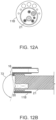
- FIGS 12A-12B show frontal and side-sectional views, respectively, of a tip adaptor 11B in association with an endoscope distal end 21, according to some exemplary embodiments of the invention.
- the circumferential extent of a tip adaptor 12B, 12C is any angle sufficient to allow a grip to be established from behind the endoscope distal portion 21 to which the tip adaptor attaches. In some embodiments, the angle is also chosen so that the adaptor can be opened wide enough to pass over the endoscope portion 21 from the side.
- FIGS 16A-16C illustrate an elastically deformable tip adaptor 12 in three configurations relative to a distal portion of an endoscope 21, according to some exemplary embodiments of the invention.
- distal interface 20 is fixedly connected to an endoscope distal region 21 at a position proximally spaced from the end itself ( Figure 13C ).
- the distance is at least, for example, 0.5-1.5 cm, 1-2.5 cm, 2-5 cm, or a shorter or longer distance from the distal end of the endoscope.
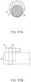
- Figures 17A-17B exemplify (in frontal and side views) a tip adaptor 13 which mounts on an endoscope 21, optionally from the side of the endoscope, and is in contact with or in proximity to a distal portion of endoscope 21 along a portion (for example, about 40% or about 50% or about 60% or about 70% or about 80%) of the endoscope circumference. In some embodiments, it does not surround as much as 50% of its circumference. In some embodiments, interface tip adaptor 13 is attachable at a variety of positions along a distal portion of endoscope 21.
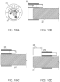
- FIGS 9A-9D illustrate a problem related to attachment of an adaptor tip 20 to an endoscope distal end 21 having variable diameter, according to some exemplary embodiments of the invention.
- the irregularity is sufficiently large as to pose an obstacle to fitting an adaptor tip 20 over the distal portion.
- the diameter 35 of expanded region 27 ( Figures 9C - 9D ) is larger than diameter 36, so that an over-the-end, form-fitting attachment proximal to the distal end of endoscope distal region 21 is impeded.
- endoscope distal region 21 is constructed with an expanded region 27, for example a ring 137 encircling the distal end.
- Ring 137 or other expanded region 27 may be provided to fulfill functional needs of endoscopes 21, for example to accommodate manipulating tools, illumination, and/or imaging optics. Nevertheless, such expansions potentially interfere with the navigability of an endoscope end. While sufficient care may have been taken in the design of the original endoscope to preserve maneuverability, adding a tip adaptor 20 that further enlarges the distal end of an endoscope 21 is potentially detrimental to successful navigation through a colon.
- a tip adaptor such as 12 or 13 attachable to an endoscope 21 at a position proximal to an expanded distal potentially allows a narrower profile of the tip adaptor and endoscope combination. Potentially, a narrower profile is more navigable.
- a tip adaptor 12 is shown attached at a region proximal to an expansion 27, permitting a profile which is within a profile 12A which the same adaptor would assume if placed directly over the expansion 27 of the endoscope distal end 21.
- FIG. 15C shows an extension 220A of housing area 220 of a tip adaptor 12D over distal end expansion 27, according to some exemplary embodiments of the invention.
- an evacuation socket 1902 comprises structures related to the assembly, sensing, safety, and/or blockage resistance of the evacuation channels of a colon cleaning device tip adaptor.
- the distal end of the tube of an evacuation channel 22 inserts into the proximal side of an evacuation channel mounting socket 1902.
- it is secured by a friction fit and/or adhesive.
- the depth of tube insertion is limited by a tube stop 1904, which comprises a partial restriction within the lumen of evacuation socket 1902.
- the partial restriction is optionally a circumferential narrowing of socket 1902.
- the stop comprises a non-circumferential raised portion of the lumen wall.
- a proximal wall 1927 of evacuation antechamber 1910 comprises one or more such distal evacuation socket apertures 1923.
- a distal wall 1925 of evacuation antechamber 1910 comprises one or more evacuation antechamber access apertures 1921.
- evacuation antechamber 1910 comprises another aperture 1910A, across which lumen 1903 is in fluid communication with antechamber 1910.
- the structures forming antechamber 1910 and its apertures comprise functions described also, for example, in relation to Figures 3A-5B , and/or 7A-7C.
- distal wall 1925 comprises an intake guard 41, insofar as it enforces a separation of the intestinal wall 1 from socket aperture 1923.
- Evacuation antechamber access aperture 1921 comprises an embodiment of an aperture or hole 60 which allows passage of sufficiently small material therethrough.
- access apertures 1921 are sized to be no larger than intake apertures 1923.
- access apertures 1921 are positioned axially distal to intake apertures 1923.
- a potential advantage of this is that it helps ensure that an oblate waste particle entering access aperture 1921 is oriented to enter the evacuation channel, rather than block across it. In this sense, access aperture 1921 potentially acts as a waste particle strainer. In cases where waste particles are too large, and/or improperly oriented to pass into an access aperture 1921, the waste particle is nevertheless less likely to become suction-impacted within the access aperture 1921, as the pressure gradient is relieved by one of the other antechamber apertures 1921, 1910A, 1907.
- Aperture 1910A by being relatively elevated, and at a relatively protected position within lumen 1903, is less likely to encounter large particles for which pre-straining is an advantage.
- aperture 1910A is divided into two or more smaller apertures, potentially also providing a straining function for the intake aperture 1923.
- Figure 23 schematically illustrates a particle 2305 entering a distal tip adaptor 2300, according to some exemplary embodiments of the invention.
- a tip 2300 (simplified to emphasize aspects related to evacuation antechamber 1910 ) is attached to a colonoscope probe 21 within lumen 1903, and an evacuation channel 22 at evacuation socket 1902. Suction is actively applied to the evacuation channel 22 such that material entering antechamber 1910 is evacuated. In some embodiments, this creates additional suction gradients 2301, 2302 from apertures 1910A and 1921, respectively.
- waste fluid with suspended solids
- level 2223 is positioned about at or above aperture 1921, waste is pulled into the antechamber. If resistance at this aperture rises, however, the corresponding rise in the steepness of the pressure gradient is reduced by suction relief action of aperture 1910A.
- Particle 2305 represents a waste particle which, though large in one dimension, has been aligned to by passage through aperture 1921 so that it can enter channel 22 rather than being jammed to across intake aperture 1923.
- the provision of pluralities of apertures provides a further functional advantage. If a single access aperture 1921 becomes blocked, for example, it is nevertheless possible for a plurality of evacuation intake apertures to continue receiving fluid from the common antechamber 1910 fed by another access aperture 1921.
- a further functional aspect related to evacuation antechamber 1910 is the rounded shaping of the distal wall 1925 such that while it provides separation of regions experiencing a steep pressure from the intestinal wall 1, it also presents a blunted front aspect 1802. Potentially, this reduces mechanical damage from poking, cutting, catching, and/or slicing. Insofar as the rounded tip shape is also tapering, the chances of catching are potentially reduced, as the shape of the tip encourages sliding away from and over wall obstructions, rather than bluntly pushing at them.
- spherical shaping though it need not be actually a section of a spherical surface
- spherical shaping also reduces the likelihood of catching on walls by suction grip, by presenting inlet aperture shapes to which the intestinal wall 1 is not well suited to simultaneously conform (and block).
- distal tip 1800, 1900 relates to the structures associated with colonoscope mounting lumen 1903.
- a colonoscope stop 1906 is provided, which protrudes into the lumen 1903 such that the placement of the cleaning tip 1800, 1900 on the colonoscope distal end is precisely limited to the point at which the colonoscope contacts stopping surface 1906A. It is a potential advantage, for example, if the colonoscope end is prevented from blocking antechamber aperture 1910A.
- tip 1800, 1900 is attached to one end of a thin-walled, flexible sleeve of a polymer (such as polyurethane, silicone rubber, or another flexible polymer) which is sized to fittingly accommodate and/or fair the colonoscope and/or other tube elements which comprise the fully assembled cleaning apparatus.
- a polymer such as polyurethane, silicone rubber, or another flexible polymer
- Potential advantages of the sleeve assembly 2104 include: allowing reversible attachment of the cleaning apparatus to a colonoscope (for example, so that the cleaning apparatus can be exchanged and/or disposed of after use); ease of integration of a cleaning system with a colonoscope probe, and/or reproducible control of the integrated cleaning system/colonoscope probe system configuration shape and relative positioning.
- a diameter of a lumen of inner sleeve 2103, in a non-expanded state ranges between, for example, 8-12 mm, 3-10 mm, 5-18 mm, or another range having the same, intermediate, larger and/or smaller bounds.
- the diameter is selected according to a diameter of a colonoscope; for example, 5%, 10%, 20% or an intermediate, larger or smaller percentage smaller (before stretching) than a diameter of a colonoscope.
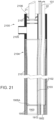
- sleeve assembly 2104 is inflatable for receiving a colonoscope probe by attachment to an inflation base 2107 of inflation jig 2100, the base 2107 comprising an inflation inlet 2105 configured to be attached to a gas pressure source for inflation.
- an inflation jig 2100 comprises a restriction tube or partial tube 2101, though which sleeve assembly 2104 is extended for receiving a colonoscope probe 21.
- Colonoscope probe 21 is optionally inserted through sealing member 2106, and fed through the inner sleeve 2103 until reaching lumen 1903 of the distal tip 1900.
- external pressure sensor socket 1914 is configured to receive a pressure sensor which senses an external pressure through external pressure sensor aperture 1916.
- a stop 1915, 1919 helps to assure proper placement of the sensor, for example, a mechanical pressure sensor such as that described in relation to pressure sensing socket 1918.
- a soft insert provides an advantage for resisting the tendency of tubes inserted thereto from being pried out of position upon application of bending forces to the cleaning assembly (if made to a softness similar to the tubes 110, the insert bends to a greater degree along with the tubes themselves as they are flexed).
- the hard shell provides an advantage for allowing a relatively lower friction material (of the body itself, and/or of a coating) to be used for regions of the tip liable to contact the intestinal wall 1.
- both components are made of polyurethane (of appropriately differing hardness).
- the outer component is coated, for example with a friction reducing material such as Parylene C, Teflon, or another low-friction material.
- the hardness of the internal tip portion 1805 is, for example, within the range of 25-40 Shore A, 30-50 Shore A, 35-55 Shore A, or within another range of softness having the same, larger, smaller, and/or intermediate bounds.
- one or more compressible chambers and/or hollows are provided which potentially augment the protective effects of a soft shell 1801.
- antechamber 1910 is optionally manufactured of material of sufficient softness and/or wall thinness such that the hollow it defines is easily collapsible upon encountering contact forces.
- shell 1801 is manufactured with other hollows within its structure.
- the wall thickness of a shell region 1803 comprises hollow regions defined by relatively thin membranes of soft material (in a honeycomb formation, for example).
- the chambers are optionally sealed or left unsealed on at least one side.
- the regions of soft and hard material are provided in different regions than shown in the figures.
- the soft material of shell 1801 optionally comprises nearly all of the material volume of a tip assembly 1800, with the dimensionally stable hard material being provided as one or more inserts (for example, a plurality of tubular inserts) to define structures such as sockets and/or apertures.
- Some embodiments of the invention comprise another alternative construction; for example, a plurality of alternating and/or intermingled soft and hard layers and/or partial or segmented shells.
- at least a portion of the relative advantages of each type of two-hardness construction is potentially obtained by such construction variations.
- the hardness of the shell portion 1801 is, for example, within the range of 25-40 Shore A, 30-50 Shore A, 35-55 Shore A, or within another range of softness having the same, larger, smaller, and/or intermediate bounds.
- the hardness of the insert tip portion 1805 is, for example, within the range of 40-60 Shore A, 60-80 Shore A, 70-90 Shore A, or within another range of softness having the same, larger, smaller, and/or intermediate bounds.
- FIG. 20 schematically illustrates a tip adaptor 2000 comprising a flexible wall guard 2001, according to some exemplary embodiments of the invention.
- the wall guard 2001 comprises one or more flexible members 2002 attached at one end to the tip body, and having a length 2002A of about, for example, 10-15 mm, 12-18 mm, 15-20 mm, 18-24 mm, or another range of lengths having the same, larger, smaller, and/or intermediate bounds.
- the total width 2002B of the wall guard 2001 is within the range of about, for example, 5-7 mm, 6-9 mm, 8-12 mm, 9-14 mm, or another range having the same, larger, smaller, and/or intermediate bounds.
- a plurality of flexible members are separated by a gap 2004; for example, a gap of 1-2 mm or another gap width.
- the wall guard 2001 is optionally sufficiently soft that it tends to elastically collapse upon exercise of sufficient force, for example, upon encountering a restriction in the colon (for example, a constriction at a colon segment boundary), such that navigation through the restriction is relatively unimpeded.
- Positions 2200 and 2213 show examples of the wall collapsed in a distal- and proximal-pointing orientation, respectively.
- the members 2002 are provided as balloons inflatable through fluid communication with a pressure source (such as an irrigation tube 101, or another tube which is specially provided for wall inflation). This optionally allows control of wall stiffness according to the current navigational requirements.
- the tip is repositioned by the wall guard to a radial position better suited to further advancement-for example, nearer to an aperture region in an intestinal restriction.
- alternate short backward and forward movements of the tip region result in the tip "scanning" within the lumen and toward and away from the intestinal wall 1 (paralleling, for example, a path like 2200 ).
- An evacuation position is optionally selected, for example, such that the evacuation access apertures 1921 are immersed, but the evacuation antechamber aperture 1910A remains clear of fluid.
- treating includes abrogating, substantially inhibiting, slowing or reversing the progression of a condition, substantially ameliorating clinical or aesthetical symptoms of a condition or substantially preventing the appearance of clinical or aesthetical symptoms of a condition.
- range format is merely for convenience and brevity and should not be construed as an inflexible limitation on the scope of the invention. Accordingly, the description of a range should be considered to have specifically disclosed all the possible subranges as well as individual numerical values within that range. For example, description of a range such as from 1 to 6 should be considered to have specifically disclosed subranges such as from 1 to 3, from 1 to 4, from 1 to 5, from 2 to 4, from 2 to 6, from 3 to 6, etc., as well as individual numbers within that range, for example, 1, 2, 3, 4, 5, and 6. This applies regardless of the breadth of the range.
Landscapes
- Health & Medical Sciences (AREA)
- Life Sciences & Earth Sciences (AREA)
- Surgery (AREA)
- Engineering & Computer Science (AREA)
- Biomedical Technology (AREA)
- Heart & Thoracic Surgery (AREA)
- Pathology (AREA)
- Radiology & Medical Imaging (AREA)
- Nuclear Medicine, Radiotherapy & Molecular Imaging (AREA)
- Biophysics (AREA)
- Physics & Mathematics (AREA)
- Optics & Photonics (AREA)
- Medical Informatics (AREA)
- Molecular Biology (AREA)
- Animal Behavior & Ethology (AREA)
- General Health & Medical Sciences (AREA)
- Public Health (AREA)
- Veterinary Medicine (AREA)
- Mechanical Engineering (AREA)
- Endoscopes (AREA)
Description
- The present invention, in some embodiments thereof, relates to a tool for use with an endoscope and, more particularly, but not exclusively, to components to be inserted in a body lumen together with an endoscope and used to clean the body lumen to facilitate visualization of the lumen by means of the endoscope. For example, some embodiments may be used with a colonoscope for cleaning of a colon during colonoscopy.
- During a colonoscopy, fecal matter is removed from a colon using pipes dedicated for the tasks of irrigation and evacuation. Typically, a colonoscope irrigation channel delivers fluid for loosening, dissolving, and/or fragmenting fecal material to the colon; and a working channel evacuates this material.
- Self-cleaning systems have been described which add irrigation and/or evacuation channels on to a colonoscope probe; for example, in International Patent Publication Nos.
WO 2009/143201, filed May 20, 2009 andWO 2010/138521, filed December 2, 2010 . -
PCT Publication WO 2009/095915 Al to NITSAN et al. discloses "The present invention is directed to a jet spray head unit suitable for being assembled circumferentially around an elongate medical instrument, comprising a ring-shaped element that is fitted with at least a first set of distally-directed apertures that extend from the distal face to the proximal face of said element, wherein each of said apertures is adapted such that the proximal end thereof may be connected to a source of pressurized irrigation fluid. The present invention further encompasses a method of treatment using said spray head unit." (Abstract)US Patent No. 5,725,476 to Yasui et al. discloses "A cap assembly of a front end of an inserting portion of an endoscope and a cap to be attached to the front end of the endoscope, comprising; a first engaging portion provided on the front end of the inserting portion of the endoscope; and, a second engaging portion provided on the cap being disengageably engaged with the first engaging portion of the endoscope. The front end of the inserting portion of the endoscope is provided with a projection whose diameter being smaller than a diameter of the front end, the projection being connected to the front end through a stepped portion." (Abstract) - According to invention, there is provided a tip adaptor of a colon cleaning system for use with a colonoscope as defined by appended
claim 1. - Further embodiments of the invention are defined by the dependent claims.
- Some embodiments of the invention are herein described, by way of example only, with reference to the accompanying drawings. With specific reference now to the drawings in detail, it is stressed that the particulars shown are by way of example, and for purposes of illustrative discussion of embodiments of the invention. In this regard, the description taken with the drawings makes apparent to those skilled in the art how embodiments of the invention may be practiced.
- In the drawings:
-
FIGs. 1A-1B present simplified schematic views of a cleaning system usable with an endoscope, according to some exemplary embodiments of the present invention; -
FIGs. 2A-2C schematically illustrate a tip adaptor which comprises a shield, according to some exemplary embodiments of the invention; -
FIGs. 2D-2E show an encounter between a portion of an intestinal wall and vacuum pulled through an evacuation lumen of tip adaptor, according to some exemplary embodiments of the invention; -
FIGs. 3A-3B show an encounter between a portion of an intestinal wall and vacuum pulled through an evacuation lumen of a tip adaptor provided with an extension, according to some exemplary embodiments of the invention; -
FIGs. 4A-4B schematically illustrate a tip adaptor which comprises a shield having at least one aperture, according to some exemplary embodiments of the invention; -
FIGs. 5A-5B illustrate drainage of fluid and suspended waste from an intestinal lumen, according to some exemplary embodiments of the invention; -
FIGs. 6A-6B illustrate a shield in relation to an imaging aperture, according to some exemplary embodiments of the invention; -
FIGs. 7A-7C schematically illustrate an example of a tip adaptor comprising a fully circumferential shield, according to some exemplary embodiments of the invention; -
FIGs. 8A-8C schematically illustrate an example of a tip adaptor comprising an end-recessed shield, according to some exemplary embodiments of the invention; -
FIGs. 9A-9D illustrate attachment of an adaptor tip to an endoscope distal end having variable diameter, according to some exemplary embodiments of the invention; -
FIGs. 10A-10D illustrate over-the-end attachment of an adaptor tip to an endoscope distal end, according to some exemplary embodiments of the invention; -
FIGs. 11A-11C schematically illustrate configurations for cleaning system tip adaptors mountable on distal portions of endoscopes, according to some exemplary embodiments of the invention; -
FIG. 11D shows an over-the-end applied tip adaptor, associated with an endoscope distal portion, according to some exemplary embodiments of the invention; -
FIGs. 12A-12B show frontal and side-sectional views, respectively, of a tip adaptor in association with an endoscope distal end, according to some exemplary embodiments of the invention; -
FIGs. 13A-13C schematically illustrate configurations for cleaning system tip adaptors mountable on distal portions of endoscopes, according to some exemplary embodiments of the invention; -
FIGs. 14A-14C demonstrate attachment of a tip adaptor to an endoscope probe comprising an expanded distal portion, according to some exemplary embodiments of the invention; -
FIGs. 15A-15B schematically illustrate different circumferential extents of elastically deformable tip adaptors, according to some exemplary embodiments of the invention; -
FIG. 15C shows an extension of housing area of a tip adaptor over a distal end expansion, according to some exemplary embodiments of the invention; -
FIGs. 16A-16C illustrate an elastically deformable tip adaptor in three configurations relative to a distal portion of an endoscope, according to some exemplary embodiments of the invention; -
FIGs. 17A-17B schematically illustrate configurations for cleaning system tip adaptors mountable on distal portions of endoscopes, according to some exemplary embodiments of the invention; -
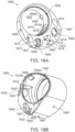
FIGs. 18A-18C schematically illustrate a tip adaptor comprising a shell and insert of different hardness, according to some exemplary embodiments of the invention; -
FIGs. 19A-19C schematically illustrate a tip adaptor comprising an evacuation antechamber, according to some exemplary embodiments of the invention; -
FIG. 20 schematically illustrates a tip adaptor comprising a flexible wall guard, according to some exemplary embodiments of the invention; -
FIG. 21 schematically illustrates a sleeve assembly in a sleeve placement jig together with components of an irrigation system and a colonoscope, according to some exemplary embodiments of the invention; -
FIG. 22 illustrates positions of a cleaning system distal region (comprising for example, an adaptor tip), in relation to an intestinal wall and a flexible wall guard; and -
FIG. 23 schematically illustrates a particle entering a distal tip adaptor, according to some exemplary embodiments of the invention. - The present invention, in some embodiments thereof, relates to a tool for use with an endoscope and, more particularly, but not exclusively, to components to be inserted in a body lumen together with an endoscope and used to clean the body lumen to facilitate visualization of the lumen by means of the endoscope. For example, some embodiments may be used with a colonoscope for cleaning of a colon during colonoscopy.
- A broad aspect of some embodiments of the invention relates to a tip adaptor for connecting a distal portion of an endoscope with a distal portion of a cleaning module for cleaning of a colon or other body lumen.
- In some embodiments of the invention, a probe of the lumen-cleaning module (cleaning system) is dimensioned for reaching to the end of a colon, or to another portion of a gastrointestinal tract. In some embodiments, the lumen-cleaning module is adapted for pumping irrigation fluid to the distal end of the probe to dislodge, disaggregate, dissolve, and/or suspend fecal matter in a colon. In some embodiments, the lumen-cleaning module is adapted for evacuating loosened fecal matter from the colon through a lumen of the probe.
- An aspect of some embodiments of the invention relates to a two-hardness or multiple-hardness construction of a tip adaptor, for example, such that an outer portion of the tip adaptor is relatively rigid, and an insert to said outer portion is relatively soft, and/or, for example, such that an outer portion of the tip adaptor is relatively soft, and an insert to said outer portion is relatively hard.
- In some embodiments of the invention, a soft insert and hard outer portion are provided.
- In some embodiments of the invention, the soft insert comprises sockets sized to receive connections to fluid transport tubes such as evacuation channels, irrigation fluid supply conduits, and/or pressure sensing tubes. In some embodiments, the soft insert serves to absorb and/or buffer movements of the fluid transport tubes, such that displacements due to tube motion relative to the tip are distributed in the body of the soft insert, rather than focused to the interface region between the fluid transport tubes and their respective sockets. In some embodiments, the hard portion of the tip adaptor is sufficiently hard to resist deformations due to direct external forces likely to be encountered during navigation of a colon. Potentially, this helps to shield the socket connections from deformations that might tend to loosen connections. Potentially, the relatively inflexible construction of the hard portion of the tip adaptor resists deformations that might tend to allow the tip to become impacted upon rather than slide over protrusions in the intestinal wall.
- In some embodiments, the deformability characteristics of the soft insert comprise movement of about 0.1 mm in response to between 1-10 Newtons of force. In some embodiments, movement corresponds to about 0.1-0.25 mm, 0.15-0.2 mm, 0.25-0.5 mm, or range of movements having the same, greater, smaller, and/or intermediate bounds.
- In some embodiments of the invention, a hard insert and soft outer portion are provided.
- Optionally, the hard insert comprises sockets sized to receive connections to fluid transport tubes such as evacuation channels, irrigation fluid supply conduits, and/or pressure sensing tubes. Optionally, use of a relatively hard insert to a soft outer portion allows manufacturing of sockets to tight tolerances for receiving fluid transport and/or pressure sensing tubes, while still allowing a soft outer portion which mitigates potentially traumatic interactions between the device head and surrounding tissue during operation.
- Potentially, use of a relatively hard insert provides dimensional stability during storage and/or in use. For example, stability of the connection of the socket to tubing is preserved by the hard insert being substantially resistant to deformation under the forces of use, and/or due to forces or creep during storage. Optionally a relatively hard insert provides dimensional stability of an aperture, for example, an aperture shaped to form and/or direct a fluid jet for cleaning. Without dimensional stability of a jetting aperture, jet force, shape, and/or direction is potentially altered during storage and/or use.
- In some embodiments, a soft outer shell of the tip adaptor reduces the potential for trauma in the tissue due to interactions with the tip adaptor. For example, the surface of the tip adaptor itself has some rubbery give to it, allowing distribution of forces to potentially prevent focusing force to a small region of soft tissue. In some embodiments, one or more portions of the tip adaptor soft shell are configured to partially and elastically collapse when receiving force, providing still further give in the tip adaptor shape.
- In some embodiments, apertures (such as jet and/or suction apertures) which are defined and made dimensionally stable by a hard insert portion are protected by a surrounding portion of soft shell. For example, the soft shell is provided with an aperture wide enough to avoid interference with the function (for example, shape and/or aiming) of a jet aperture, and surrounding the jet aperture to prevent direct tissue interactions with it. Optionally, a soft shell aperture is provided spaced from and in front of a hard insert-defined suction aperture, potentially protecting tissue from encountering a hard edge of the suction aperture.
- In some embodiments, the deformability characteristics of the soft shell (for example, the shell where it directly overlies a hard insert portion) comprise movement of about 0.1 mm in response to between 1-10 Newtons of force. In some embodiments, movement corresponds to about 0.1-0.25 mm, 0.15-0.2 mm, 0.25-0.5 mm, or a range of movements having the same, greater, smaller, and/or intermediate bounds. In some embodiments, the soft shell comprises one or more collapsible chambers and/or hollows, and is configured to allow elastic collapse to an extent (for example, of 1 mm, 2 mm, 3 mm, 4 mm, 5 mm, or another greater or smaller extent) which is at least partially determined by the dimensions of the chamber or hollow, for example in response to between 1-10 Newtons of force. The hollow is likewise, for example, about 1 mm, 2 mm, 3mm, 4 mm, 5 mm, or another greater or smaller distance in extent in the direction of collapse. Alternatively-for example, in embodiments where the chambers are sealed-the collapse is to an intermediate range governed by the compressibility of the chamber walls and/or contents.
- It is to be understood that the extent and/or contiguity of the relatively hard and relatively soft parts of the tip adaptor is optionally subject to further variations and combinations. Optionally, for example, a shell comprises both hard and soft portions. For example, corners, leading surfaces, and/or other surface of the shell are formed as soft, yielding, and/or compressible portions of the shell, while other parts of the shell (exposed as surfaces and/or supporting the compressible portions from within) are formed as relatively hard portions of the shell. Additionally or alternatively, the insert portion is formed with hard, stiff, and/or incompressible portions which provide dimensional stability of parts such as socket shapes and irrigation inlet shapes, together with, for example, soft linings of sockets (potentially to allow slight deformation upon experiencing force, but thin enough so that the functionally important dimensional stability provided by the hard portion is not compromised). Additionally or alternatively, a hard socket and/or irrigation inlet is embedded within a matrix of softer material. Potentially, this allows some give and/or relative motion of sockets to absorb forces exerted on the tip, while preserving dimensional stability needed, for example, to securely hold fittings and/or reliably shape jet formation. Thus, a tip adaptor is optionally provided with multiple layers of alternating hardness and softness, within the shell and/or within the insert, which potentially allows providing at least some of the advantages of each material type.
- Furthermore, although the embodiments herein are described with respect to an optionally separable "shell" and "insert", it is to be understood that both elements are optionally manufactured as a single unit. Alternatively, either element is optionally manufactured as a plurality of parts, which optionally interconnect to one another, and/or are held to the tip adaptor by the complementary part or assembly of parts. For example, in some embodiments, an insert is optionally formed as a plurality of inserts which are separately fit into the shell. Additionally or alternatively, a shell is formed of parts which attach separately to an insert, for example, by being molded into place, by a snap fit, and/or by adhesive attachment.
- Moreover, it is to be understood that the terms "soft" and "hard" as used herein relate to the relative elastic deformability of materials and/or construction (including plastic polymer compositions such as polyurethane, and/or constructions comprising hollows, thin walls, or other deformable and/or reducible shapes), and, in particular, deformability in response to compressive forces.
- An aspect of some embodiments of the invention relates to structures for protecting colon tissues from accidental damage by suction used for evacuation of fecal material.
- In some embodiments of the invention, an intake guard is provided as a portion of a tip adaptor. In some embodiments, the intake guard comprises a wall positioned to divert suction into the intake of an evacuation channel away from the tissue of a lumenal wall during insertion to a colon. It is a potential advantage to provide such a guard wall, as the intake aperture of the evacuation port is subject in some embodiments to suction.
- Tissue approaching an unshielded evacuation port may be damaged by suction, particularly if the tissue seals across the port such that the pressure gradient drop occurs substantially across the tissue. Another potential advantage of a guard wall is to protect the function of evacuation port itself. In some embodiments, a sensor system allows a controller to reduce and/or reverse suction strength upon detection of an occlusion of the system. It is a potential advantage to reduce the occurrence of occlusions by tissue in order to maintain a higher rate of evacuation throughput by the cleaning system.
- The "intake aperture" or "intake cross-section" of the evacuation lumen refers to the most distal region of the evacuation lumen where the evacuation lumen is substantially uniform in cross-section (for example, within ±10% of its diameter and/or cross-sectional area along the main body of the evacuation lumen). In embodiments where a guard wall forms the last portion of the evacuation lumen, the intake aperture or intake cross-section terminates where the guard wall shape defines (or, where change is continues, where it begins to define, for example by a slope change) a substantial change in the shape of the evacuation lumen cross-section. A "suction intake" or "suction inlet" marks a region beyond which fluid is not in the evacuation lumen at all. The region interconnecting a suction intake and an intake aperture or cross-section is defined, in some embodiments, by a guard wall. In some embodiments, the interconnecting region comprises an evacuation antechamber.
- In some embodiments, the suction intake defined by the guard wall is of a larger diameter than the evacuation lumen or lumens it protects, for example, larger in area by 50%, 100%, 200%, 500%, or another intermediate, smaller, or larger difference. It is a potential advantage for the suction intake to be larger, such that it is more difficult to bring tissue close to it where the tissue experiences a high pressure gradient. In some embodiments of the invention, the suction intake is formed to a non-circular shape, such as an oval, crescent, and/or slit. In some embodiments of the invention, a shortest distance across the suction intake is smaller than the smallest dimension across an evacuation lumen, for example, 75%, 50%, 25%, or an intermediate, larger, or smaller relative size. In some embodiments, the distance of maximum distal extension of the guard wall is, for example, 3-5 mm, 4-10 mm, 6-15 mm, 10-20 mm, or another shorter or longer distance. In some embodiments, the thickness of the intake guard wall is at least 0.1-0.2 mm, 0.1-0.3 mm, 0.2-0.5 mm, 0.4-1.0 mm, or another larger or smaller thickness.
- According to the embodiment, the inner diameter of an evacuation channel extended by a guard wall is, for example, 2.1 mm, 3 mm, 4 mm, 4.2 mm, 4.5 mm, 5 mm, 5.5 mm, 6 mm, another larger or smaller diameter, or any diameter in between. The number of evacuation channels which a guard wall protects may be 1, 2, 3, 4 or more evacuation channels, according to the embodiment.
- It is a potential advantage for the suction intake to have such a smaller relative dimension, to help ensure than particles which pass it are small enough in at least one dimension to pass through the evacuation lumen without occluding it. It is also a potential advantage for the suction intake to have a dimension of relatively large extent (for example the length of a slit or oval, which may itself be straight and/or curved), such that it is unlikely that any single large particle could act to block it completely. In some embodiments, the ratio of longest to shortest dimension of a suction intake is, for example, 1:2, 1:3, 1:5, 1:10, or another intermediate, smaller, or larger ratio.
- In some embodiments of the invention, the intake guard is adapted with one or more additional features which avoid interference with and/or support functioning of the endoscope probe and/or cleaning system. In some embodiments, the intake guard, extending distally from the endoscope probe end, is provided with a tapering shape. The intake guard, in some embodiments, is more fully circumferential (optionally, fully circumferential) than is required simply to shield the evacuation port. It is a potential advantage to provide a taper on the intake guard, for example, so that the narrower tip presented thereby can insert into (and potentially help to pry apart) intestinal constrictions during forward navigation. The wall of the intake guard tapers, for example, to the diameter of the distal end of the colonoscope probe. In some embodiments, the guard tapers more or less, for example, to within about 120% of the colonoscope probe diameter, or within about 100%, 90%, 80%, 50% or another larger or smaller relative taper diameter. In some embodiments, the tapering extent is different at different circumferential locations. For example, a taper, in some embodiments, is shorter (distally) and/or wider (radially) at a portion of the adaptor which is closer to an imaging and/or illumination means comprised within the colonoscope. Potentially, this avoids blocking the view and/or casting a visible shadow. In some embodiments, the taper begins behind the distal end of a colonoscope, and terminates at about the distal end.
- In some embodiments, the intake guard is provided with one or more vent apertures that allow fluid to cross the intake guard wall, while still preventing tissue of a lumenal wall from approaching regions of high negative pressure. In some embodiments, apertures are positioned at locations on the guard wall which are sufficiently far from the region of maximal pressure drop that there is no damaging pressure drop across them. This may be, for example, near the open end of the guard wall that defines the suction aperture. Additionally or alternatively, an aperture is located or near an interior cross-section defined by the guard wall which is relatively large, such that flow is slower, and the pressure drop correspondingly less. Potentially, having a dedicated, wall- and/or debris-protected suction aperture separate from the vent apertures reduces the pressure gradient across the vent apertures to a level which is unable to grab and/or injure intestinal tissue.
- A vent aperture provides a potential advantage for allowing more complete removal of fluid from a body lumen. A guard wall, for example, might otherwise act as a barrier (for example, because of an inward taper) that prevents fluid from reaching proximity to the evacuation port.
- In some embodiments, an intake guard is shaped to a rounded distal surface, for example, a surface approximating the surface of a sphere, ovoid, or other substantially rounded shape having a radius of about 10-20 mm. In some embodiments, the surface curvatures approximate a radius within a range of about 5-15 mm, 10-25 mm, 15-25 mm, 20-30 mm, or another range of radii having the same, larger, smaller and/or intermediate bounds.
- In some embodiments, an intake guard positions vent apertures (evacuation channel access apertures) such that an evacuation antechamber is positioned between the vent apertures and the intake apertures of the evacuation chamber itself. In some embodiments, the evacuation antechamber comprises an open region fluidly interconnecting a plurality of evacuation intake apertures proximally. In some embodiments, the evacuation antechamber comprises another aperture which is positioned in a location sheltered from waste and/or intestinal wall suction contact (for example, in fluid communication with a lumen of the tip which is difficult to block, due the size, shape and/or position of its own openings). Potentially, the sheltered aperture acts as a pressure shunt to prevent a suction gradient from increasing across one or a plurality of vent apertures if the one or plurality of vent apertures is blocked (for example, by waste particles).
- In some embodiments, vent/access apertures are arranged axially in line with evacuation intake apertures, at a size about equal to or smaller than the intake apertures. Potentially, this relative positioning and relative size allows the access apertures to operate as size- and/or orientation-selective filters for waste particles entering the evacuation antechamber, such that fewer waste particles reach the relatively high suction gradient of the intake aperture that are too large and/or oriented to block it.
- An aspect of some embodiments of the invention relates to variable-site positioning for a tip adaptor which mates a cleaning system probe to an endoscope probe.
- In some embodiments of the invention, the tip adaptor is mateable to a distal end of an endoscope probe directly from the side. In some embodiments, this is obtained by a slit along the side of the tip adaptor which is expandable to receive the endoscope probe, and contractible to lock the tip around the endoscope probe. Optionally, the expandability and contractibility comprise elasticity of the tip adaptor materials. In some embodiments of the invention, the tip adaptor is mateable to a distal end of an endoscope probe over the distal end of the endoscope probe, and configured to be tightened around a portion of the endoscope probe proximal to the end. Potentially, one or both of these configurations allows a tip adaptor to be positioned for a desired balance between: sufficiently distal to provide colonic cleaning but sufficiently proximal to reduce interference with probe navigation in a lumen.
- In some embodiments, an endoscope probe is provided with an expanded tip (for example, to accommodate structures for endoscope functions) and a cleaning system tip adaptor is attachable proximal to this expansion. It is a potential advantage to attach proximal to the region of expansion, since this allows a tip adaptor, in some embodiments, to conform to a smaller-diameter region. Conforming to a smaller-diameter region in turn potentially reduces the overall diameter added to the distal portion of the endoscope probe by the cleaning system probe.
- An aspect of some embodiments of the invention relates to a flexible guard wall which acts as a variable-distance standoff between a cleaning system tip adaptor and the intestinal wall.
- In some embodiments, the guard wall is positioned to stick radially away from the position of the fluid access and/or intake aperture of an evacuation channel, such that suction applied to the evacuation channel is restricted from pulling intestinal wall portions up to the aperture itself (with potentially resulting injury). In some embodiments, the wall is provided with sufficient stiffness to act as a spring that bends to convert distal-proximal motions of the colon cleaning distal end into motion across the transverse cross-section of the colon. For example, with the guard wall bent backward from the tip adaptor (bent proximally) the tip body moves toward or away from the wall as the tip is advanced distally or proximally, respectively. In some embodiments, this motion is used to aim jets, set a level of tip immersion for evacuation, and/or select a tip position for navigation of a restriction, constriction, and/or barrier to distal movement.
- Before explaining at least one embodiment of the invention in detail, it is to be understood that the invention is not necessarily limited in its application to the details of construction and the arrangement of the components and/or methods set forth in the following description and/or illustrated in the drawings. The invention is capable of other embodiments or of being practiced or carried out in various ways.
- For convenience of exposition, cleaning systems, modules, and/or methods described herein are sometimes referred to as "colon cleaning" systems, modules and/or methods. Colon cleaning is contemplated as a common use of embodiments of the invention. However, it is to be understood that methods and devices taught herein may also be used to clean other portions of an intestine and/or other body lumens.
- Accordingly, the term "colon cleaning" as applied to these methods and devices encompasses cleaning not only the colon, but also other portions of an intestine and/or other body lumens. For example, some embodiments of the invention are potentially useful in cleaning as part of a procedure for diagnosing and treatment bleeding in the upper GI tract.
- Reference is now made to
Figures 1A-1B , which are simplified schematic views of acleaning system 100 usable with an endoscope 10 (which may be a colonoscope), according to some exemplary embodiments of the present invention.Figure 1B showsinset region 100A ofFigure 1A in greater detail. - In some
embodiments cleaning system 100 comprises anendoscope 10, and in someembodiments cleaning system 100 is independent of and optionally usable with anendoscope 10. In some embodiments,system 100 may also be used independently as an insertable cleaning system not connected to or used with an endoscope. -
System 100 comprises aninterface device 20 which in some embodiments is designed to be disposable, i.e. for one-time use. In some embodiments interface 20 is a distal portion ofcleaning system 100, and serves to connectsystem 100 to a distal portion of anendoscope 10, as shown in the figure. In some embodiments,endoscope 10 is a colonoscope. In some embodiments,endoscope 10 comprises animaging port 107 and/or other imaging means at adistal portion thereof 21. -
Interface 20 is optionally attached to at least one and optionally a plurality offlexible tubes 110, also optionally disposable. In some embodimentsflexible tubes 110 are sufficiently long to connectinterface 20 to proximal components ofcleaning system 100 whileinterface 20 and a distal portion ofendoscope 10 are advanced into a body lumen such as a colon. In anexemplary embodiment tubes 110 are 4 meters long. In other embodiments,tubes 110 are between 2 and 5 meters long. Optionally,tubes 110 are taped or otherwise temporarily attached toendoscope 10 by attachments 112 (e.g. biocompatible tape, or releasable clamps positioned at convenient intervals, for example about every 10-20 cm, every 5-35 cm, or over another longer or shorter interval). Tapes may optionally be localized tape portions, and may optionally be one or more long tape pieces spirally wrapped around an endoscope and its accompanying tubes. - In some embodiments (for example, any of the interface device embodiments described herein), the distal portion of a
colonoscope probe 21 has a diameter, of, for example, 5-8 mm, 6-10 mm, 8-12 mm, 10-15 mm, 14-20 mm or another range of diameters having range boundaries equal, higher, lower, or intermediate to the ranges given. A colonoscope distal end diameter may be variable within, for example, the distal 1-10 cm of its length, due to irregularities in construction, structures for steering, and/or structures for containing colonoscope instrumentation. An interface device for connecting to the distal end of a colonoscope probe extends, for example, 1-2 mm, 2-5 mm, 4-8 mm, 6-12 mm, 10-20 mm, 10-30 mm, or another range of distances having bounds equal, intermediate, smaller, or larger. - In some embodiments,
tubes 110 are positioned aroundendoscope 10, may wrap aroundendoscope 10 and/or around each other, and in general are positioned with respect toendoscope 10 according to convenience and/or in a manner which enhances simplicity of operation and/or flexibility of body-insertable portions ofsystem 100 together withendoscope 10. - In some embodiments,
tubes 110 comprise anevacuation channel 22 which connectsinterface device 20 to a vacuum source, which may for example be apump 120 and/or a connection to acentralized vacuum system 122 such as are available in some hospitals and clinics. In some embodiments,system 100 comprises a plurality of evacuation channels 22 (also called "suction tubes 22" herein), such as for example two, or three, or four, ormore tubes 22. In some embodiments, a lumen of anendoscope working channel 23 is usable as an evacuation channel. In some embodiments, apump 120 is reversible to purge an evacuation channel. According to the embodiment, the inner diameter of an evacuation channel is, for example, 2.1 mm, 3 mm, 4 mm, 4.2 mm, 4.5 mm, 5 mm, 5.5 mm, 6 mm, another larger or smaller diameter, or any diameter in between. - In some embodiments, interface device 20 (and/or any of the other interface devices described herein) comprises structure which adapts from the intake aperture of an
evacuation channel 22 to another shape at the distal-most portion of the suction intake, for example, a slit, an oval, an annulus, and/or a partial annulus. In some embodiments, two or more evacuation channels are combined into a single suction inlet by the interface device. In some embodiments, a single evacuation channel is split into two or more separate suction inlets. In some embodiments, the area of the suction inlet aperture is larger than the cross-section of the evacuation channel lumen, for example, 50% larger, 100%, 150%, 300%, 500%, or another intermediate, larger or smaller difference in area. - In some embodiments one or more or
tubes 110 serves as anirrigation tube 101, connected to a fluid source which is a source of water or another liquid and/or a liquid/gas combination. In some embodiments, one or more working channels ofendoscope 10 serves asirrigation tube 101. - In some methods of use,
irrigation tube 101 supplies a cleaning fluid to interfacedevice 20, which delivers it into a body lumen such as a colon, optionally under pressure, where it serves to wash the colon, and loosens and partially dissolves fecal matter which is then suctioned into one or more suction portals (also called "suction inlets" herein) 95B in interface 20 (as shown in figures discussed below), and thence intoevacuation channel 22 and/or 23, which transport the material out of the body and deliver it to an optionalfecal matter collector 118. Vacuum (i.e. suction) in tubes is optionally regulated by a valve or regulator orvariable pump 120, optionally connected to vacuumsource 122. Delivery of suction to tube(s) 22 and of irrigation fluid to tube(s) 101 is optionally regulated by acontroller 125, optionally receiving commands from an operator through auser interface 130 such as a computer console and/or a knob or lever or other manual command. - Reference is now made to
Figures 2A-2C , which schematically illustrate atip adaptor 20 which comprises the wall of anintake guard 41, according to some exemplary embodiments of the invention. - For some embodiments of the invention,
Figures 2C and 2A -2B present side cross-sectional and end cross-sectional views at different depths respectively of atip adaptor 20 comprising anintake guard 41 designed to distance body tissue from anevacuation portal 95 which might be blocked by body tissue and/or which might damage body tissue. - In some embodiments,
intake guard 41 is positioned between an evacuation portal such asportal 95 and tissues of a body when said tip adaptor is inserted in a body lumen. For example,intake guard 41 protects tissues of the walls of a colon when suction is applied to the colon throughevacuation portal 95. In some embodiments,intake guard 41 extends along at least 20% of the circumference oftip adaptor 20, extends distally fromtip adaptor 20. In some embodiments,intake guard 41 extends along at least 35%, 50%, 80%, or 100% of the circumference oftip adaptor 20, or a lesser fraction of the circumference, or any intermediate circumference fraction. In some embodiments, the distance of maximum extension ofintake guard 41 is, for example, 3-5 mm, 4-10 mm, 6-15 mm, 10-20 mm, or another shorter or longer distance. The distance of shortest extension at any given point around its circumference, in some embodiments, is between 0 mm and any distance up to the longest distance of extension. In some embodiments, the thickness ofintake guard wall 41 is at least 0.1-0.2 mm, 0.1-0.3 mm, 0.2-0.5 mm, 0.4-1.0 mm, or another larger or smaller thickness. In some embodiments,intake guard 41 is rigid or semi-rigid, such that it maintains its shape under at least the pressure used to normally advance the endoscope probe into the body lumen. A rigid orsemi-rigid intake guard 41 potentially assists in forward penetration of an advancing distal end of an endoscope probe. In some embodiments,intake guard 41 is flexible, sufficiently so that it collapses, for example, when pressed directly to a lumenal wall. This is a potential advantage for reducing injury as an endoscope probe advances. In some embodiments,intake guard 41 is designed with a flexibility/rigidity which comprises both navigation assistance and safety collapse, such that it collapses, for example, under an advancing pressure of 1-4 PSI, 3-8 PSI, 5-10 PSI, 8-15 PSI, or another higher or lower threshold of pressure.Intake Guard 41 is an optional feature of any of the cleaning systems and/or tip adaptors described herein. - Protection offered by
intake guard 41 is potentially by one or more of a selection of mechanisms, as now described, and/or by another mechanism. In some embodiments, shield 41 positions a suction inlet which is in fluid communication with anevacuation lumen 22 to a location and/or orientation which is less exposed to wall contacts than thebare intake aperture 95 of theevacuation lumen 22. - Optionally, the position is a more medial position, potentially increasing a distance between a body lumen wall and a region of a high pressure gradient. Optionally, the orientation is shifted to make contacts with the wall less likely, for example, a rotation which is about mid-way between an orientation perpendicular to the distal-proximal axis of the device (which may tend to come into contact with wall protrusions during distal motion) and an orientation parallel to the distal-proximal axis (which may tend to come into contact with flat regions of the wall). Mid-way, in some embodiments of the invention, comprises an angle which is at least 30° degrees away from both axes, or at least 35°, 40°, or another intermediate, larger, or smaller angle of separation. In some embodiments, the aperture is both moved and rotated. For example, the suction inlet illustrated in
Figures 2A-2C , defined by the protruding wall section ofintake guard 41, rotates the suction inlet by about 90° to point in a medial direction, and moves the aperture in a medial direction. - In some embodiments of the invention,
intake guard 41 protects by adopting a shape which is unlikely to be matched by an occluding section of wall. For example, the lip of the intake guard may be formed to define non-planar aperture mouth (for example, the margin of the intake guard forms a lip which is not substantially contained within a single plane), and/or the aperture mouth may be guarded on one or more sides by structures that prevent a wall section from overlying the aperture. For example, the distal end of the colonoscope itself prevents the aperture ofintake guard 41 inFigure 2C from being fully occluded by a large extent of intestinal wall. In some embodiments, interference in the region of the suction inlet mouth prevents fully occlusion by an extent of wall which is continuous beyond 10 mm from the point of contact, or beyond 5-10 mm, 10-15 mm, 8-20 mm, or another range of continuous extent having bounds which are the same, intermediate, smaller, or larger. - In some embodiments of the invention,
intake guard 41 protects by creating a larger suction inlet area, decreasing the likelihood of total occlusion. For example,irregularities 1A of an intestinal wall are limited in size, so a sufficiently large aperture, even if oriented to the surface of the irregularity, is not occluded. In some embodiments of the invention, the suction inlet is large enough to prevent total occlusion by a flap of tissue which is less than 5 mm in protruding extent. In some embodiments, occlusion is prevented for flaps of tissue having protruding extent less than 5-10 mm, 2-5 mm, 8-12 mm, or another range of extents having bounds equal, intermediate, larger, or smaller. - Another potential advantage of a large suction inlet area is to help ensure that regions of high pressure differential with the intracolonic pressure are located deep within the intake structures of the evacuation channel and/or intake guard, rather than exposed near the intake aperture itself.
- Reference is now made to
Figures 7A-7C , which schematically illustrate an example of atip adaptor 19A comprising a fullycircumferential intake guard 41, according to some exemplary embodiments of the invention.Figures 7A-7B show frontal views at different section planes.Figure 7C shows a view in horizontal cross-section. - In some embodiments,
intake guard portion 42 protrudes a shorter distance away from the tip than aregion 41A protectingevacuation lumen 22. A potential advantage of a fullycircumferential intake guard 41 is to provide a narrower entry point for an advancing into a body lumen. - In some embodiments, the
shorter region 42 is positionable to be radially nearer to animaging device 50, to reduce or prevent obstruction of a field ofview 72 ofimaging device 50 by the extension ofintake guard 41. In some embodiments, one ormore positioning elements tip adaptor 19A relative to the end ofdistal endoscope region 21. - Reference is now made to
Figures 8A-8C , which schematically illustrate an example of atip adaptor 19B comprising an end-recessedintake guard 41B, according to some exemplary embodiments of the invention.Figures 8A-8B show frontal views at different section planes.Figure 8C shows a view in horizontal cross-section. - In some embodiments,
intake guard 41B is recessed away from the distal end oftip adaptor 19B. A potential advantage of this position is to protect of anevacuation lumen 22, with lowered obstruction of the progress and/or field of view ofdistal endoscope region 21. In particular, the extreme distal end of the advancing distal end is expanded only by the thickness oftip adaptor 19A used to house the anchoring structures of the adaptor. In some embodiments, one ormore positioning elements tip adaptor 19A relative to the end ofdistal endoscope region 21. - Referring again to
Figures 2A-2C ,chamber 43 oftip adaptor 20 is for housing a distal end of anendoscope 21. Achamber 220 in the figure is for housing and/or connecting to (and functionally extending) atube 22 which optionally connects proximally to a vacuum source as described above.Suction 71 produced by a proximal vacuum source is delivered in some embodiments bytube 22 andchamber 220 to anevacuation portal 95. - In some embodiments of the invention,
tip adaptor 20 comprises adistal intake guard 41. Potentially,intake guard 41 serves to separate body lumen wall tissue or other body tissue from direct exposure to high levels of vacuum potentially present in anevacuation portal 95. - Reference is now made to
Figures 2D and 2E , which show an encounter between aportion 1A of anintestinal wall 1 and vacuum pulled indirection 71 through anevacuation lumen 22 oftip adaptor 20, according to some exemplary embodiments of the invention. InFigure 2D , an advancing distal end of anendoscope 21 approaches anirregularity 1A inwall 1. InFigure 2E ,irregularity 1A is pulled to the aperture ofevacuation lumen 22. It is, however, a potential advantage to prevent this mode of contact between an active evacuation portal and soft body tissue. Faults which potentially occur in this scenario include: - body tissues sucked towards and into the evacuation portal blocking the portal, preventing proper functioning of a lumen-cleaning process; and
- traumatizing of body tissues sucked into the evacuation portal.
- Suction strong enough to provide efficient and rapid evacuation of fecal matter from a colon (for example) is potentially strong enough to create hematoma, ruptured blood vessels, or other undesirable outcomes in tissue subject to a strong suction.
- Reference is now made to
Figures 3A and 3B , which show an encounter between aportion 1A of anintestinal wall 1 and vacuum pulled indirection 71 through anevacuation lumen 22 oftip adaptor 20, provided with anextension 41, according to some exemplary embodiments of the invention. InFigure 3A , an advancing distal end of anendoscope 21 approaches anirregularity 1A inwall 1. InFigure 3B ,irregularity 1A is pushed forward, away from the aperture ofevacuation lumen 22, protecting it fromsuction force 71. - Returning now to
Figures 2A-2C , in some embodiments,extension 41 stands between evacuation portal 95 and sensitive tissue such as the wall of a colon, and protects that tissue from damage while preventing blockage ofevacuation portal 95 by body tissue. In some embodiments,intake guard 41 is positioned nearevacuation portal 95. - Optionally a plurality of
shields 41 is positioned near a plurality ofevacuation portals 95. Optionally,intake guard 41 is positioned around all or major portions oftip adaptor 20 and not be limited to positions in direct proximity toevacuation portals 95. - Optionally,
intake guard 41 is curved towards a central axis oftip adaptor 20, as shown inFigure 2C . - Reference is now made to
Figures 6A-6B , which illustrate anintake guard 41 in relation to animaging aperture 50, according to some exemplary embodiments of the invention. - Optionally,
intake guard 41 is positioned to avoid or partially avoid limiting the field ofview 72 of optical components ofendoscope 10. - Reference is now made to
Figures 4A-4B , which schematically illustrate atip adaptor 20 which comprises anintake guard 41 having at least oneaperture 60, according to some exemplary embodiments of the invention. - In some embodiments of the invention,
intake guard 41 may comprise one or more (optionally small) holes 60 through which cleaning can occur. This configuration is shown in side cross-section inFigure 4B and in front cross-section inFigure 4A . - Optionally, holes 60 may have rounded edges so that they will not cut or scrape tissues of the lumen walls as
tip adaptor 20 advances in the body lumen. - The appropriate size and location of
holes 60 may depend on the characteristics of the material to be cleaned, the nature of the irrigation used, the strength of the suction provided, and various other operational parameters.Figures 4A and 4B present exemplary and non-limiting embodiments. In some embodiments, holes 60 are placed such that they overlie interior regions exposed to suction which experience a relatively small pressure differential with the intracolonic pressure. For example the holes may be placed near the distal end of anintake guard wall 41, and/or may be placed such that the nearest portion of the chamber formed on the interior side of theintake guard wall 41 is relatively large. - In some embodiments, this larger chamber region corresponds to an effectively increased "pipe" diameter, resulting in a lower pressure drop, for example according to Bernoulli's principle. This is a potential advantage for the safety of the tissue, and/or for reduction of the tendency of suction to grab approaching tissue.
- In some embodiments, a potential tension exists within the goal of evacuating as much waste volume as practical, while exposing the tissues of the colonic segment to a pressure gradient which is as gentle as practical. In embodiments of this compromise, suction as such is not relied upon to dislodge particles. It is also a potential advantage to put apertures leading to the evacuation channel where they are exposed to the least pressure differential. It is another potential advantage for structures leading to the evacuation channel to have wide cross sections near such apertures, narrowing as they recede from regions which might be exposed to tissue.
- According to some optional methods of use, a physician turns on suction in
tube 22 when hole(s) 60 are appropriately positioned over an area needing cleaning, and turns off or reduces suction when holes 60 are positioned over vulnerable tissue. - Reference is now made to
Figures 5A and 5B , which illustrate drainage of fluid and suspendedwaste 30 from an intestinal lumen, according to some exemplary embodiments of the invention. In each figure, the lumen contained byintestinal wall 1 is being drained by vacuum pulled indirection 71 through anevacuation lumen 22 oftip adaptor 20, provided with anextension 41. - In
Figure 5A , a distal end of anendoscope 21 is partially submerged in fluid and suspendedwaste 30.Suction 71 is unable to completely drainwaste suspension 30, due to thebarrier comprising extension 41. InFigure 5A , a distal end of anendoscope 21 is partially submerged in fluid and suspendedwaste 30.Suction 71 is provided access to remnants of drainedwaste suspension 30, by one ormore holes 60 provided inextension 41. - Note that
tip adaptor 20, in some embodiments, is configured to remain clear of colonoscope elements located at the colonoscope tip, comprising, for example (as shown inFigure 2A ),illumination LED 105,imaging port 107, workingchannel 102, and irrigation channel 103. - Reference is now made to
Figures 11A-11D ,13A-13C , and 17A-17B, which schematically illustrate configurations for cleaningsystem 100tip adaptors 20 mountable ondistal portions 21 ofendoscopes 10, according to some exemplary embodiments of the invention. - It is to be understood that, in some embodiments "tip adaptors" shown in these figures and referenced elsewhere herein are connectable to
tubes 110 and to other portions of a cleaning system such as thecleaning system 100 ofFigures 1A-1B . - It is also to be understood that configurations of what is generally referred to as "
tip adaptor 20" herein should be understood to include (changed as necessary) all individually described tip adaptors described herein (for example,tip adaptors 11A-11C, 12, 13, and 19A-19B), and all other devices conforming to descriptions of "tip adaptors" presented herein as embodiments of the invention. -
Figures 11A-11D schematically illustrate sectional side views oftip adaptors 11A-11C (and 20) mounted on a distal end of anendoscope 10. - In exemplary embodiments shown in
Figures 11A-11C ,tip adaptor circumferential projection 16 or other feature which assures thattip adaptor endoscope 21 in a fixed positional relationship. - Reference is now made to
Figures 12A-12B , which show frontal and side-sectional views, respectively, of atip adaptor 11B in association with an endoscopedistal end 21, according to some exemplary embodiments of the invention. - It is a potential advantage to adjust the shape of
projection 16 to accommodate the function of features located at the end ofdistal endoscope portion 21. In some embodiments, for example,projection 16 may be retracted from portions of thetip adaptor 11B which are positionable in proximity to the field ofview 72 of animaging device 50. This retraction allows the positioning function to operate without impairing the functional operation of the endoscope optics and/or other features such as irrigation, working channels, and/or illumination. -
Figures 11D ,13A-13C , and 17A-17B are simplified schematics of tip adaptors which are either variably positionable on distal portions ofendoscopes 21, or which are fixedly positioned near but not at a distal end of anendoscope 21, according to some embodiments of the invention. -
Figures 13A-C show front and front- and side- sectional views of tip adaptor 12 (which is a tip adaptor 20) configured to be fittingly applied over a distal portion of anendoscope 21 from a lateral direction. In some embodiments,interface tip adaptor 12 is elastically deformable, and sized to gripendoscope end 21 in a pressure grip (direction of grip pressure is indicated, for example, by arrows 26). Optionally,tip adaptor 12 is fitted by a user to a selectable position at or near the end of distal portion ofendoscope 21. In some embodiments,tip adaptor 12, is optionally slideable for positioning along the distal body ofendoscope 21. In some embodiments,tip adaptor 12 grips endoscopedistal end 21 with a sufficient strength to resist movement on endoscopedistal end 21 under influence of pressures normally exerted onendoscope 21 during insertion in a colon or other body lumen. - Reference is now made to
Figures 15A-15B , which schematically illustrate different circumferential extents of elastically deformable tip adaptors 12B, 12C, according to some exemplary embodiments of the invention. - In some embodiments, the circumferential extent of a tip adaptor 12B, 12C is any angle sufficient to allow a grip to be established from behind the endoscope
distal portion 21 to which the tip adaptor attaches. In some embodiments, the angle is also chosen so that the adaptor can be opened wide enough to pass over theendoscope portion 21 from the side. - In some embodiments, for example, tip adaptor 12B (
Figure 15A ) extends around about 2/3 of the circumference of the endoscope. It should be understood that the extent of circumferential wrapping is variable, depending on the diameter of the endoscope at the point of attachment. - In some embodiments, for example, tip adaptor 12C (
Figure 15B ), extends only a small amount past 180° of the endoscope circumference at the point of attachment. In some embodiments, the security of attachment is increased by decreasing the flexibility of the tip adaptor 12C, such that the pressing to the underlying endoscope is harder. - Thus, in some embodiments, tip adaptors which self-attach by means of their own elastic restoring force may be constructed with a relaxed-state aperture which is anywhere in size from 0% of the endoscope diameter (slit-like) to a value just sufficiently small enough allow establishing a grip. The relaxed-state aperture size may thus be, for example, 20%-80% of the endoscope diameter, or another larger or smaller size. In some embodiments, the adaptor extends from fitting about 50% around the endoscope probe profile to any larger value. A more completely enclosing adaptor potentially provides a firmer grip, with a trade-off for this comprising a larger increase in endoscope probe diameter.
- The material of the tip adaptor body (for adaptors 12B, 12C, or any other tip adaptor described herein) can be a silicone rubber or another polymer material, for example, a polymer resin otherwise used in manufacture of a colonoscope or colon cleaning system insertion tube. Exemplary Shore A durometer values for the material of a tip adaptor are between 50-70 Shore A durometer units. In some embodiments, a Shore A durometer range of 50-55 Shore A, 50-60 Shore A, 55-65 Shore A, 70-80 Shore A, 70-90 Shore A, or another range of durometer having bounds equal, intermediate, higher or lower is used.
- In some embodiments, a transparent material is used to form a tip adaptor (for example, tip adaptor 12B, 12C, or any other tip adaptor described herein). A potential advantage of transparency is more direct determination of the positioning of the adaptor on the colonoscope end.
- Reference is now made to
Figures 16A-16C , which illustrate an elasticallydeformable tip adaptor 12 in three configurations relative to a distal portion of anendoscope 21, according to some exemplary embodiments of the invention. - Configurations shown are pre attachment (
Figure 16A ), mid-attachment (Figure 16B ), and after attachment (Figure 16C ). The sequence illustrates the flexibility ofadaptor 12 for insertion over an endoscope from the side, and its capability for attachment by shape restoration once pressed onto an endoscope tube. - In some embodiments, a position for
tip adaptor 20 with respect to a distal end ofendoscope 21 is selected by a user according to preference and/or according to a given clinical situation, andtip adaptor 20 attached to endoscopedistal end 21 according to the position selected. In some embodiments,tip adaptor 20 and/or attachedtubes 110 are disposable objects intended for one-time use. - In some embodiments,
distal interface 20 is fixedly connected to an endoscopedistal region 21 at a position proximally spaced from the end itself (Figure 13C ). The distance is at least, for example, 0.5-1.5 cm, 1-2.5 cm, 2-5 cm, or a shorter or longer distance from the distal end of the endoscope. - A potential advantage of the configurations shown in
Figures 13A-13C and 17A-17B is ensuring the optics of endoscope 10 a full field of view. Iftip adaptor 20 is positioned near the end ofendoscope 21 but is somewhat distanced from that end, then even unusually large tip adaptors may not interfere with full field of view for the endoscope optics. - In some methods of use in some embodiments, an
endoscope 10 with attachedcleaning system 100 is advanceable throughout a length of a colon with the cleaning system in use during the advance, so that the cleaning system cleans fecal matter from the length of colon. Optionally, the endoscope is subsequently gradually retracted through the cleaned colon for inspection and/or treatment. Under this method, the fact thattip adaptor 20 is positioned proximally to the distal end of the endoscope is convenient both during advancing/cleaning and during retracting/observing. During advancing, potentially, the distal tip is more easily able to penetrate restricted spaces, in virtue of not having to support the added bulk of the adaptor tip at the point of penetration. During retraction, potentially, the adaptor tip is clear of interfering with illumination and/or imaging elements in virtue of being physically out of their field of illumination and/or view. -
Figures 17A-17B exemplify (in frontal and side views) atip adaptor 13 which mounts on anendoscope 21, optionally from the side of the endoscope, and is in contact with or in proximity to a distal portion ofendoscope 21 along a portion (for example, about 40% or about 50% or about 60% or about 70% or about 80%) of the endoscope circumference. In some embodiments, it does not surround as much as 50% of its circumference. In some embodiments,interface tip adaptor 13 is attachable at a variety of positions along a distal portion ofendoscope 21. Optionally,tip adaptor 13 is held in place by anattachment 14 such as a bonding tape, clamp and/or any other mechanical, bonding, and/or gluing means; a strap, and/or by attachments 112 along connectingtubes 110, themselves connected to tipadaptor 13 along the length ofendoscope 10 as described above with reference toFigures 1A-1B . - In some embodiments,
interface tip adaptors endoscope 21, to suit a physician's convenience and/or to suit the clinical requirements of a particular case. It is a potential advantage of tip adaptors having flexible and/or side-attachable,tip adaptor 13 that they are attachable for use with endoscopes of a variety of shapes and/or diameters. In some embodiments,tip adaptor 13 is constructed of elastically flexible material to further make it adaptable to endoscopes of varying sizes. For similar reasons,tip adaptor 13 is optionally adaptable to being mounted on a portion ofdistal endoscope 21 having a non-circular or asymmetrical cross-section. - Embodiments shown in
Figures 11D ,13A-13C , and 17A-17B are optionally usable to position distal outlets of "cleaning tubes" (that is, one or more irrigation tubes and/or one or more evacuation tubes) at a user-selected position with respect to a distal end of an endoscope. - Reference is now made to
Figures 10A-10D , which illustrate over-the-end attachment of anadaptor tip 20 to an endoscopedistal end 21, according to some exemplary embodiments of the invention. - In some embodiments,
tip adaptor 20 is attachable over the end of endoscope distal region 21 (Figure 10B ) to a range of positions relative to the distal end. The position may be flush or nearly flush with the end (Figure 10C ), or it may be offset proximally by adistance 28, for example, 0.5-1.5 cm, 1-2 cm, 1.5-3 cm, or another longer or shorter offset length. - Reference is now made to
Figures 9A-9D , which illustrate a problem related to attachment of anadaptor tip 20 to an endoscopedistal end 21 having variable diameter, according to some exemplary embodiments of the invention. - In some embodiments, an endoscope
distal portion 21 comprises a relativelyuniform diameter 36 extending proximally from the endoscope distal end (Figures 9A- 9B). In some embodiments of the invention, the endoscope distal portion is not of uniform diameter, as shown here, but may comprise irregularities, for example, due to endoscope wrapping, steering mechanism, and/or other structures. The segmented appearance of endoscopedistal portion 21 inFigures 1A-1B reflects these irregularities. It should be noted that it is a potential advantage of elastically deformable embodiments, for example, those ofFigures 13A-13C , that they potentially adjust to such irregularities automatically. - In some embodiments, the irregularity is sufficiently large as to pose an obstacle to fitting an
adaptor tip 20 over the distal portion. For example, thediameter 35 of expanded region 27 (Figures 9C-9D ) is larger thandiameter 36, so that an over-the-end, form-fitting attachment proximal to the distal end of endoscopedistal region 21 is impeded. - Reference is now made to
Figures 14A-14C , which demonstrate attachment of atip adaptor 12 to an endoscope probe comprising an expandeddistal portion 27, according to some exemplary embodiments of the invention. - In some embodiments, endoscope
distal region 21 is constructed with an expandedregion 27, for example aring 137 encircling the distal end.Ring 137 or other expandedregion 27 may be provided to fulfill functional needs ofendoscopes 21, for example to accommodate manipulating tools, illumination, and/or imaging optics. Nevertheless, such expansions potentially interfere with the navigability of an endoscope end. While sufficient care may have been taken in the design of the original endoscope to preserve maneuverability, adding atip adaptor 20 that further enlarges the distal end of anendoscope 21 is potentially detrimental to successful navigation through a colon. - A tip adaptor such as 12 or 13 attachable to an
endoscope 21 at a position proximal to an expanded distal potentially allows a narrower profile of the tip adaptor and endoscope combination. Potentially, a narrower profile is more navigable. InFigures 14A-14C , for example, atip adaptor 12 is shown attached at a region proximal to anexpansion 27, permitting a profile which is within aprofile 12A which the same adaptor would assume if placed directly over theexpansion 27 of the endoscopedistal end 21. - Reference is now made to
Figure 15C , which shows anextension 220A ofhousing area 220 of a tip adaptor 12D overdistal end expansion 27, according to some exemplary embodiments of the invention. - In some embodiments, tip adaptor 12D is configured to attach distally to the end of
distal endoscope region 21, with ashort extension 220A, configured to rise over an expandedregion 27 and project forward, bringing an aperture of anevacuation channel 95, for example, further forward while the main body of thetip adaptor 12 remains at a more sheltered proximal position. - Reference is now made to
Figure 11D , which shows an over-the-end applied tip adaptor 11C, associated with an endoscopedistal portion 21, according to some exemplary embodiments of the invention. - A potential advantage of side-mounting tip adaptors is seen by comparison of
Figure 11D withFigure 14C . InFigure 11D , the adaptor 11C is separated by adistance 28 from the distal end ofendoscope 21, after sliding over adistal expansion 27. However, the resulting configuration is not well fitted, and has excessive diameter relative to the diameter achievable with a configuration such as that ofFigure 14C . Even in the case of an over-the-end configuration mounted more securely at the distal end, as inFigure 11C , thetip adaptor 11B is potentially more obstructive than the configuration ofFigure 14C . - Reference is now made to
Figures 18A-18C , which schematically illustrate atip adaptor 1800 comprising ashell 1801 and aninsert 1805, according to some exemplary embodiments of the invention. In some embodiments, the shell is relatively soft, and the insert is relatively hard. In some embodiments, the insert is relatively soft, and the shell is relatively hard. The two alternative configurations potentially provide alternative sets of benefits, as described hereinbelow. Reference is also made toFigures 19A-19C , which schematically illustrate atip adaptor 1900 comprising anevacuation antechamber 1910, according to some exemplary embodiments of the invention. - In some embodiments of the invention, a
tip adaptor colonoscope mounting lumen 1903, sized and shaped to receive the distal end of a colonoscope. Optionally, thetip adaptor - one or more evacuation
channel mounting sockets 1902 for tubes of the evacuation channel, - one or more irrigation
channel mounting sockets 1912 for tubes providing irrigation fluid, and/or - one or more
pressure sensor sockets - In some embodiments of the invention, an
evacuation socket 1902 comprises structures related to the assembly, sensing, safety, and/or blockage resistance of the evacuation channels of a colon cleaning device tip adaptor. - In some embodiments, the distal end of the tube of an
evacuation channel 22 inserts into the proximal side of an evacuationchannel mounting socket 1902. Optionally, it is secured by a friction fit and/or adhesive. Optionally, the depth of tube insertion is limited by atube stop 1904, which comprises a partial restriction within the lumen ofevacuation socket 1902. The partial restriction is optionally a circumferential narrowing ofsocket 1902. Optionally, the stop comprises a non-circumferential raised portion of the lumen wall. - Distal to the tube stop, in some embodiments, an evacuation channel tip
pressure sensing aperture 1909 is provided. Optionally, the pressure sensing aperture comprises a lumen extending between evacuationchannel mounting socket 1902, andpressure sensor socket 1918. In some embodiments, ahole 1907 is provided opposite thesensing aperture hole 1909 in the wall ofevacuation socket 1902. Thehole 1907 is optionally created during the process of manufacture to provide access for the creation ofhole 1909. - Additionally or alternatively, it serves as a secondary suction relief aperture.
- In some embodiments,
socket 1902 terminates at a distalevacuation socket aperture 1923, leading intoevacuation antechamber 1910. As such,socket aperture 1923 also comprises theintake aperture 95 of the evacuation channel. - Optionally, a
proximal wall 1927 ofevacuation antechamber 1910 comprises one or more such distalevacuation socket apertures 1923. In some embodiments, adistal wall 1925 ofevacuation antechamber 1910 comprises one or more evacuationantechamber access apertures 1921. Optionally,evacuation antechamber 1910 comprises anotheraperture 1910A, across which lumen 1903 is in fluid communication withantechamber 1910. - In some embodiments, the
structures forming antechamber 1910 and its apertures comprise functions described also, for example, in relation toFigures 3A-5B , and/or 7A-7C. For example,distal wall 1925 comprises anintake guard 41, insofar as it enforces a separation of theintestinal wall 1 fromsocket aperture 1923. Evacuationantechamber access aperture 1921 comprises an embodiment of an aperture orhole 60 which allows passage of sufficiently small material therethrough. - Potential advantages of the structure of
antechamber 1910 and its apertures can be considered in terms of the pressures experienced by different sizes of granulated waste material as it passes into theantechamber 1910, and thence into one of theevacuation intake apertures 1923. With the evacuation channel side of the cleaning probe oriented to down (as in, for example,Figures 5A-5B ), fluid level is readily reduced to a low depth, as theaccess apertures 1921 are positioned low on the tip head, and a sufficient pressure gradient is generated by suction from theevacuation channel 22 acrossaccess apertures 1921 to move fluid volume. - Optionally,
access apertures 1921 are sized to be no larger thanintake apertures 1923. Optionally,access apertures 1921 are positioned axially distal tointake apertures 1923. A potential advantage of this is that it helps ensure that an oblate waste particle enteringaccess aperture 1921 is oriented to enter the evacuation channel, rather than block across it. In this sense,access aperture 1921 potentially acts as a waste particle strainer. In cases where waste particles are too large, and/or improperly oriented to pass into anaccess aperture 1921, the waste particle is nevertheless less likely to become suction-impacted within theaccess aperture 1921, as the pressure gradient is relieved by one of theother antechamber apertures Aperture 1910A, by being relatively elevated, and at a relatively protected position withinlumen 1903, is less likely to encounter large particles for which pre-straining is an advantage. Optionally, however,aperture 1910A is divided into two or more smaller apertures, potentially also providing a straining function for theintake aperture 1923. - Reference is now made to
Figure 23 , which schematically illustrates a particle 2305 entering adistal tip adaptor 2300, according to some exemplary embodiments of the invention. - In some embodiments, a tip 2300 (simplified to emphasize aspects related to evacuation antechamber 1910) is attached to a
colonoscope probe 21 withinlumen 1903, and anevacuation channel 22 atevacuation socket 1902. Suction is actively applied to theevacuation channel 22 such thatmaterial entering antechamber 1910 is evacuated. In some embodiments, this createsadditional suction gradients apertures level 2223 is positioned about at or aboveaperture 1921, waste is pulled into the antechamber. If resistance at this aperture rises, however, the corresponding rise in the steepness of the pressure gradient is reduced by suction relief action ofaperture 1910A. Resistance can rise, for example, upon encountering a portion ofintestinal wall 1, for example as shown in relation toFigures 2D-2E . Potentially, shunting of the pressure gradient acts to reduce an incidence of suction-related injury. Particle 2305 represents a waste particle which, though large in one dimension, has been aligned to by passage throughaperture 1921 so that it can enterchannel 22 rather than being jammed to acrossintake aperture 1923. - In some embodiments, the provision of pluralities of apertures provides a further functional advantage. If a
single access aperture 1921 becomes blocked, for example, it is nevertheless possible for a plurality of evacuation intake apertures to continue receiving fluid from thecommon antechamber 1910 fed by anotheraccess aperture 1921. - A further functional aspect related to
evacuation antechamber 1910 is the rounded shaping of thedistal wall 1925 such that while it provides separation of regions experiencing a steep pressure from theintestinal wall 1, it also presents a bluntedfront aspect 1802. Potentially, this reduces mechanical damage from poking, cutting, catching, and/or slicing. Insofar as the rounded tip shape is also tapering, the chances of catching are potentially reduced, as the shape of the tip encourages sliding away from and over wall obstructions, rather than bluntly pushing at them. Potentially, rounded shaping of the whole of the front surface ("spherical" shaping, though it need not be actually a section of a spherical surface) also reduces the likelihood of catching on walls by suction grip, by presenting inlet aperture shapes to which theintestinal wall 1 is not well suited to simultaneously conform (and block). - Another aspect of
distal tip colonoscope mounting lumen 1903. In some embodiments, acolonoscope stop 1906 is provided, which protrudes into thelumen 1903 such that the placement of thecleaning tip contacts stopping surface 1906A. It is a potential advantage, for example, if the colonoscope end is prevented from blockingantechamber aperture 1910A. - Reference is now made to
Figure 21 , which schematically illustrates asleeve assembly 2104 in asleeve placement jig 2100 together with components of an irrigation system and acolonoscope 21, according to some exemplary embodiments of the invention. - In some embodiments of the invention,
tip sleeve assembly 2104 include: allowing reversible attachment of the cleaning apparatus to a colonoscope (for example, so that the cleaning apparatus can be exchanged and/or disposed of after use); ease of integration of a cleaning system with a colonoscope probe, and/or reproducible control of the integrated cleaning system/colonoscope probe system configuration shape and relative positioning. - In some embodiments, the sleeve assembly comprises an inner sleeve 2103, adapted for receiving a
colonoscope probe 21. Inner sleeve 2103 is circumferentially surrounded by anouter sleeve 2102, including one or more add-ontubes - In some embodiments, a diameter of a lumen of inner sleeve 2103, in a non-expanded state, ranges between, for example, 8-12 mm, 3-10 mm, 5-18 mm, or another range having the same, intermediate, larger and/or smaller bounds. Optionally, the diameter is selected according to a diameter of a colonoscope; for example, 5%, 10%, 20% or an intermediate, larger or smaller percentage smaller (before stretching) than a diameter of a colonoscope. As particular examples: for a colonoscope having a diameter of 12 mm, the inner diameter is smaller than the colonoscope's diameter in a non-expanded state by 0.1-5 mm, 1-3 mm, 0.1-0.9 mm or another range of sizes having the same, intermediate, larger and/or smaller bounds.
- In some embodiments,
sleeve assembly 2104 is inflatable for receiving a colonoscope probe by attachment to aninflation base 2107 ofinflation jig 2100, thebase 2107 comprising aninflation inlet 2105 configured to be attached to a gas pressure source for inflation. Optionally, aninflation jig 2100 comprises a restriction tube orpartial tube 2101, though whichsleeve assembly 2104 is extended for receiving acolonoscope probe 21.Colonoscope probe 21 is optionally inserted through sealingmember 2106, and fed through the inner sleeve 2103 until reachinglumen 1903 of thedistal tip 1900. - Optionally, the flexible sleeve is secured by a circumference around
attachment channel 1905A. Optionally, the sleeve comprises an outer tube and at least one inner tube; optionally, the inner tube is attached toattachment channel 1905A. Optionally,adhesive introduction aperture 1905 is provided, leading from the outside of the tip leading tolumen 1903 andattachment channel 1905A. Optionally, the fairing tube is secured tochannel 1905A by placement of one end withinlumen 1903 and pressing againstchannel 1905A, followed by adhesive injection all around the lumen. Returning toFigures 18A-19C , in some embodiments of the invention,irrigation channel 101 terminates attip tube receiving socket 1912. Optionally,socket 1912 is elongated to allow two or more separate irrigation tubes to insert alongside each other. Optionally, insert depth into the socket is set by one or more irrigation tube stops 1913. In some embodiments, one ormore irrigation outlets 1920 are provided for eachsocket 1912. Optionally, theirrigation outlets 1920 comprise cylindrical holes oriented along the distal-proximal axis of the tip body. Optionally, theirrigation outlets 1920 are otherwise shaped and/or oriented for jetting-for example, comprising a tapered lumen, and/or aimed off the distal-proximal axis for distributing and/or aiming the irrigation fluid spray. - In some embodiments of the invention,
sensor sockets pressure sensor socket 1918 is optionally provided with a sensor which is linked throughsensing aperture 1909 to one ormore evacuation sockets 1902 for sensing of pressure and/or pressure changes therein. In some embodiments, an electronic pressure sensor is provided. In some embodiments, a mechanical pressure sensor is provided. For example, a pressure sensor optionally comprises a fluid-filled tube to which a test pressure is proximally applied. As pressure at the distal tip rises and/or falls, the volume moved by the test pressure changes, which is optionally transduced into a measurement and/or indication of distal tip pressure. - In some embodiments, external
pressure sensor socket 1914 is configured to receive a pressure sensor which senses an external pressure through externalpressure sensor aperture 1916. Optionally, astop pressure sensing socket 1918. - In some embodiments of the invention, a
tip assembly 1800 comprises a relativelyhard shell 1801, with asofter mounting portion 1805. Optionally, mountingportion 1805 comprises an insert into a receivingaperture 1801A ofhard shell 1801. Potentially, a soft insert/hard shell configuration provides an advantage by allowing the material to be selected according to the functions performed by eachportion tubes 110, the insert bends to a greater degree along with the tubes themselves as they are flexed). - Another potential advantage of the two-hardness construction is to enhance elastic friction fitting of the various small tubes which connect to the tip; for example, by making
sockets intestinal wall 1. Optionally, both components are made of polyurethane (of appropriately differing hardness). Optionally, the outer component is coated, for example with a friction reducing material such as Parylene C, Teflon, or another low-friction material. - In some embodiments, the hardness of the
internal tip portion 1805 is, for example, within the range of 25-40 Shore A, 30-50 Shore A, 35-55 Shore A, or within another range of softness having the same, larger, smaller, and/or intermediate bounds. - In some embodiments, the hardness of the
external tip portion 1801 is, for example, within the range of 40-60 Shore A, 60-80 Shore A, 70-90 Shore A, or within another range of softness having the same, larger, smaller, and/or intermediate bounds. - In some embodiments of the invention, a
tip assembly 1800 comprises a relativelysoft shell 1801, with aharder mounting portion 1805. Optionally, mountingportion 1805 comprises an insert into a receivingaperture 1801A ofsoft shell 1801. Potentially, a soft shell/hard insert configuration provides an advantage by allowing the material to be selected according to the functions performed by eachportion - For example, a hard insert potentially provides dimensional stability to the tip adaptor interfaces with tubing connectors such as
sockets apertures 1920 which optionally direct and/or shape fluid jets. Potentially, a hard insert is manufacturable to closer tolerances than a soft insert, for example to achieve tighter fitting, and/or closer control of jet aperture characteristics. During storage, a hard insert potentially resists creep, sagging, or other deformation which could potentially affect performance. During use, dimensional stability potentially prevents forces exerted on the tip from distorting, dislodging and/or loosening socket-tube connections. Potentially, dimensional stability of fluid jet apertures prevents distortion which affects the aiming and/or jet forming characteristics of the aperture. - In some embodiments, a soft shell protects tissue from encounters with hard portions of the tip. In general, providing a soft "skin" for the
shell 1801 potentially helps to prevent damaging effects of poking and/or scraping. For example, a soft construction forshell 1801 softens the edges around apertures such ascolonoscope mounting lumen 1903,irrigation outlet 1920, and/orevacuation socket aperture 1923. Asoft shell 1801 also potentially distributes contact forces at other parts of thetip assembly 1800, for example at outer corners and/or curves. - In some embodiments, one or more compressible chambers and/or hollows are provided which potentially augment the protective effects of a
soft shell 1801. For example,antechamber 1910 is optionally manufactured of material of sufficient softness and/or wall thinness such that the hollow it defines is easily collapsible upon encountering contact forces. - In some embodiments, the
antechamber 1910 is flexible enough to allow elastic collapse with light pressure (for example, a pressure of between 1-10 Newtons, or another greater or smaller pressure). The collapse pressure is optionally chosen to be light enough that it is unlikely to damage the colon and/or at a level which is ordinarily encountered during advance within the colon. Optionally, collapsing pressure is deliberately brought to bear on theantechamber 1910 during use. Potentially, the collapsing action allows mechanically clearance of blockages within the chamber, and/or at one of the entrances to/exits from the chamber. - Additionally or alternatively,
shell 1801 is manufactured with other hollows within its structure. For example, the wall thickness of ashell region 1803 comprises hollow regions defined by relatively thin membranes of soft material (in a honeycomb formation, for example). The chambers are optionally sealed or left unsealed on at least one side. - In some embodiments, the regions of soft and hard material are provided in different regions than shown in the figures. For example, the soft material of
shell 1801 optionally comprises nearly all of the material volume of atip assembly 1800, with the dimensionally stable hard material being provided as one or more inserts (for example, a plurality of tubular inserts) to define structures such as sockets and/or apertures. Some embodiments of the invention comprise another alternative construction; for example, a plurality of alternating and/or intermingled soft and hard layers and/or partial or segmented shells. In some embodiments, at least a portion of the relative advantages of each type of two-hardness construction (soft inside, hard outside; hard inside, soft outside) is potentially obtained by such construction variations. For example, hard sockets and/or jet apertures (potentially providing dimensional stability for connection/jet formation) are optionally embedded in a softer matrix (potentially allowing parts to move with respect to one another without being dislodged thereby); the softer matrix is optionally embedded in a harder outer part (optionally helping to preserve overall strength and/or shape of the adaptor), and the harder outer part itself is optionally provided with soft regions which act as force-absorbing and/or edge shielding bumpers. - Optionally, one or both of the soft and hard components are made of polyurethane (of appropriately differing hardness). Optionally, the outer component is coated, for example with a friction reducing material such as Parylene C, Teflon, or another low-friction material.
- In some embodiments, the hardness of the
shell portion 1801 is, for example, within the range of 25-40 Shore A, 30-50 Shore A, 35-55 Shore A, or within another range of softness having the same, larger, smaller, and/or intermediate bounds. In some embodiments, the hardness of theinsert tip portion 1805 is, for example, within the range of 40-60 Shore A, 60-80 Shore A, 70-90 Shore A, or within another range of softness having the same, larger, smaller, and/or intermediate bounds. - Reference is now made to
Figure 20 , which schematically illustrates atip adaptor 2000 comprising aflexible wall guard 2001, according to some exemplary embodiments of the invention. - In some embodiments of the invention, a
tip adaptor 2000 comprises aflexible wall guard 2001, which acts as a spacing, positioning and/or aiming aid during colon cleaning operations. - In some embodiments, the
wall guard 2001 comprises one or moreflexible members 2002 attached at one end to the tip body, and having alength 2002A of about, for example, 10-15 mm, 12-18 mm, 15-20 mm, 18-24 mm, or another range of lengths having the same, larger, smaller, and/or intermediate bounds. In some embodiments, thetotal width 2002B of thewall guard 2001 is within the range of about, for example, 5-7 mm, 6-9 mm, 8-12 mm, 9-14 mm, or another range having the same, larger, smaller, and/or intermediate bounds. Optionally, a plurality of flexible members are separated by agap 2004; for example, a gap of 1-2 mm or another gap width. - In some embodiments, the members of
wall guard 2001 are sufficiently flexible to fully bend through arange 2006 of about 180° or more. In some embodiments, the maximum bending range is, for example, about 150°, 160°, 170°, 180°, 190°, or another larger, smaller, or intermediate maximum range. In some embodiments, the wall additionally or alternatively is configured to flex along its length, for example through aflexing range 2008. In some embodiments, the maximal flexing range is optionally from about doubled over (180°), or a smaller range such as about 90°, about 45°, or another maximum range which is larger, smaller, or intermediate. A paired-rectangle "rabbit ear" configuration is shown inFigure 20 ; however, it is to be understood that other shapes are also embodiments of the invention-for example, triangular, oval, semi-circular, or another shape. In some embodiments of the invention, the thickness of the wall guard members is varied according to distance from the tip, in order to encourage more or less bending along the length, according to the specific bending characteristics desired. The hardness of the wall guard members 2002 (which comprise, for example, polyurethane or another rubber polymer) are, for example, about 20-30 Shore A, 30-45 Shore A, 40-55 Shore A, or within another range of hardness having the same, larger, smaller, and/or intermediate bounds. It is to be understood that thewall guard 2001 is optionally provided with any of the cleaning system tip embodiments described herein. Optionally, thewall guard 2001 is integrally formed with a soft outer shell such asshell 1801, optionally surrounding an insert such as mountingportion 1805. - Reference is now made to
Figure 22 , which illustratespositions intestinal wall 1 and aflexible wall guard 2001. -
Wall guard 2001 provides a potential advantage by acting as a soft (atraumatic) stand-off from the intestinal wall through which acleaning system tip 2000 navigates. Potentially, this reduces instances of suction attachment to the intestinal wall. - Nevertheless, the
wall guard 2001 is optionally sufficiently soft that it tends to elastically collapse upon exercise of sufficient force, for example, upon encountering a restriction in the colon (for example, a constriction at a colon segment boundary), such that navigation through the restriction is relatively unimpeded.Positions members 2002 are provided as balloons inflatable through fluid communication with a pressure source (such as anirrigation tube 101, or another tube which is specially provided for wall inflation). This optionally allows control of wall stiffness according to the current navigational requirements. - In some embodiments of the invention, the
wall guard 2001 serves as a device that helps to position the tip radially within the colon. For example: as the tip is advanced fromposition 2207,wall guard members 2002 tend to flex backward and toward the tip body to a position approximating that ofline 2006A and/orposition 2213, such that the tip can more closely approach theintestinal wall 1. However, with a slight backward pull, themembers 2002 tend to straighten, for example, towardposition 2008A and/or 2207. This potentially pushes the tip away from the wall. An optional alternative maneuver is to bend the wall forward by withdrawing the tip proximally; from this position, advancing rises up on the walls (sequence ofpositions jet aiming directions - Additionally or alternatively, the tip is repositioned by the wall guard to a radial position better suited to further advancement-for example, nearer to an aperture region in an intestinal restriction. Optionally, alternate short backward and forward movements of the tip region (for example, between
positions 2201 and 2213) result in the tip "scanning" within the lumen and toward and away from the intestinal wall 1 (paralleling, for example, a path like 2200). This potentially distributes the energy of irrigation jets over acleaning target 2222, and/or allows selection of a position suited for draining fluid from the intestine relative to a waste level 2223 (allowing, for example, positioning an evacuation intake zone betweenlevels 2232 and 2233). An evacuation position is optionally selected, for example, such that theevacuation access apertures 1921 are immersed, but theevacuation antechamber aperture 1910A remains clear of fluid. - Optionally, rotation of the device puts more force on one of the
wall members 2002 than on the other, as another method of guard-wall mediated steering. Optionally, the device is deliberately rotated by about 90° to move the guard wall out of the way and bring a portion of an evacuation access aperture nearer to a lowerintestinal wall 1 portion, such that small amounts of remaining fluid can be evacuated. - As used herein, the term "about" refers to within ±10%.
- The terms "comprises", "comprising", "includes", "including", "having" and their conjugates mean: "including but not limited to".
- The term "consisting of" means: "including and limited to".
- The term "consisting essentially of" means that the composition, method or structure may include additional ingredients, steps and/or parts, but only if the additional ingredients, steps and/or parts do not materially alter the basic and novel characteristics of the claimed composition, method or structure.
- As used herein, the singular form "a", "an" and "the" include plural references unless the context clearly dictates otherwise. For example, the term "a compound" or "at least one compound" may include a plurality of compounds, including mixtures thereof.
- The words "example" and "exemplary" are used herein to mean "serving as an example, instance or illustration". Any embodiment described as an "example or "exemplary" is not necessarily to be construed as preferred or advantageous over other embodiments and/or to exclude the incorporation of features from other embodiments.
- The word "optionally" is used herein to mean "is provided in some embodiments and not provided in other embodiments". Any particular embodiment of the invention may include a plurality of "optional" features except insofar as such features conflict.
- As used herein the term "method" refers to manners, means, techniques and procedures for accomplishing a given task including, but not limited to, those manners, means, techniques and procedures either known to, or readily developed from known manners, means, techniques and procedures by practitioners of the chemical, pharmacological, biological, biochemical and medical arts.
- As used herein, the term "treating" includes abrogating, substantially inhibiting, slowing or reversing the progression of a condition, substantially ameliorating clinical or aesthetical symptoms of a condition or substantially preventing the appearance of clinical or aesthetical symptoms of a condition.
- Throughout this application, various embodiments of this invention may be presented in a range format. It should be understood that the description in range format is merely for convenience and brevity and should not be construed as an inflexible limitation on the scope of the invention. Accordingly, the description of a range should be considered to have specifically disclosed all the possible subranges as well as individual numerical values within that range. For example, description of a range such as from 1 to 6 should be considered to have specifically disclosed subranges such as from 1 to 3, from 1 to 4, from 1 to 5, from 2 to 4, from 2 to 6, from 3 to 6, etc., as well as individual numbers within that range, for example, 1, 2, 3, 4, 5, and 6. This applies regardless of the breadth of the range.
- Whenever a numerical range is indicated herein, it is meant to include any cited numeral (fractional or integral) within the indicated range. The phrases "ranging/ranges between" a first indicate number and a second indicate number and "ranging/ranges from" a first indicate number "to" a second indicate number are used herein interchangeably and are meant to include the first and second indicated numbers and all the fractional and integral numerals therebetween.
- Although the invention has been described in conjunction with specific embodiments thereof, it is evident that many alternatives, modifications and variations will be apparent to those skilled in the art. Accordingly, it is intended to embrace all such alternatives, modifications and variations that fall within the scope of the appended claims.
- In addition, citation or identification of any reference in this application shall not be construed as an admission that such reference is available as prior art to the present invention. To the extent that section headings are used, they should not be construed as necessarily limiting.
- It is appreciated that certain features of the invention, which are, for clarity, described in the context of separate embodiments, may also be provided in combination in a single embodiment. Conversely, various features of the invention, which are, for brevity, described in the context of a single embodiment, may also be provided separately or in any suitable subcombination or as suitable in any other described embodiment of the invention. Certain features described in the context of various embodiments are not to be considered essential features of those embodiments, unless the embodiment is inoperative without those elements.
Claims (15)
- A tip adaptor (1800, 1900) with dimensionally stable sockets, for use with a colonoscope probe in a colon cleaning system, the tip adaptor comprising a shell (1801) and an insert (1805):the shell having a hollow region sized to fittingly accommodate the insert, and at least one mounting lumen (1903) sized and shaped to receive a distal end of a colonoscope probe therein;said tip adaptor characterized in that:the insert is relatively rigid and comprises a plurality of sockets (1902, 1912), each socket being configured to fittingly accommodate the distal end of one or more respective fluid transport tubes; andthe shell comprises an elastic component of a softer material than the insert, the shell being deformable around the insert in response to external force, while the insert remains in place and substantially undeformed;such that said plurality of sockets are made dimensionally stable by said rigid insert while being protected by a surrounding portion of said shell.
- The tip adaptor of claim 1, wherein the soft shell defines at least one elastically collapsible hollow.
- The tip adaptor of claim 2, wherein the collapsible hollow comprises a guard wall which extends across and is spaced from an aperture of at least one of the sockets along a longitudinal axis of the socket.
- The tip adaptor of claim 3, wherein the guard wall comprises an aperture of the collapsible hollow.
- The tip adaptor of claim 3, wherein the aperture of the socket is a suction intake aperture.
- The tip adaptor of claim 5, wherein the aperture of the guard wall has substantially the same size and shape as the suction intake aperture.
- The tip adaptor of claim 3, wherein the guard wall is spaced from the aperture along a longitudinal axis of the socket by at least 5 mm.
- The tip adaptor of claim 2, wherein the collapsible hollow is sufficiently flexible to elastically collapse upon being pressed from within against a portion of colon wall, the collapse occurring at a force below one that damages the portion of colon wall.
- The tip adaptor of claim 1, wherein the shell comprises an aperture surrounding an aperture of at least one of the sockets.
- The tip adaptor of claim 9, wherein the aperture of the socket is an irrigation aperture.
- The tip adaptor of claim 10, wherein the irrigation aperture is shaped to form fluid into a jet upon the supply of fluid therethrough, and the aperture of the shell is sufficiently large to avoid interference with the jet.
- The tip adaptor of claim 1, wherein the tip adaptor comprises a socket sized to receive a distal portion of the colonoscope probe.
- A system for use with a colonoscope probe, comprising:an evacuation channel sized for insertion to a distal segment of a colon; andthe tip adaptor of claim 1, wherein the tip adaptor is attached to the distal end of the evacuation channel.
- The tip adaptor of claim 1, comprising a colon spacer integrally formed with the shell, attached to a circumference of the tip adaptor and extending radially therefrom;
the colon spacer being sufficiently flexible that it collapses upon receiving pressure due to forward motion of the tip adaptor into a radially restricted region of colon. - The tip adaptor of claim 1, wherein the hardness of the insert is between 40-90 Shore, and the hardness of the shell is between 25-55 Shore.
Applications Claiming Priority (2)
| Application Number | Priority Date | Filing Date | Title |
|---|---|---|---|
| US14/722,400 US10881277B2 (en) | 2013-11-21 | 2015-05-27 | Distal front end for coordinated positioning of an endoscope with a suction device |
| PCT/IL2016/050544 WO2016189533A1 (en) | 2015-05-27 | 2016-05-25 | Distal front end for coordinated positioning of an endoscope with a suction device |
Publications (4)
| Publication Number | Publication Date |
|---|---|
| EP3302219A1 EP3302219A1 (en) | 2018-04-11 |
| EP3302219A4 EP3302219A4 (en) | 2019-04-24 |
| EP3302219C0 EP3302219C0 (en) | 2024-07-03 |
| EP3302219B1 true EP3302219B1 (en) | 2024-07-03 |
Family
ID=57395734
Family Applications (1)
| Application Number | Title | Priority Date | Filing Date |
|---|---|---|---|
| EP16799477.1A Active EP3302219B1 (en) | 2015-05-27 | 2016-05-25 | Distal front end for coordinated positioning of an endoscope with a suction device |
Country Status (2)
| Country | Link |
|---|---|
| EP (1) | EP3302219B1 (en) |
| WO (1) | WO2016189533A1 (en) |
Families Citing this family (7)
| Publication number | Priority date | Publication date | Assignee | Title |
|---|---|---|---|---|
| US10265461B2 (en) | 2013-08-29 | 2019-04-23 | Motus Gi Medical Technologies Ltd. | Colon cleaning system with automatic self-purging features |
| US9949618B2 (en) | 2013-11-21 | 2018-04-24 | Motus Gi Medical Technologies Ltd. | Apparatus and method for coupling between a colonoscope and add-on tubes |
| WO2015075721A1 (en) | 2013-11-21 | 2015-05-28 | Motus Gi Medical Technologies Ltd. | Distal front end for coordinated positioning of an endoscope with a suction device |
| WO2015155776A2 (en) | 2014-04-09 | 2015-10-15 | Motus Gi Medical Technologies Ltd. | Cleaning method for prepless colonoscopy |
| JP2021533895A (en) | 2018-08-16 | 2021-12-09 | モータス ジーアイ メディカル テクノロジーズ リミテッド | Integrated endoscopic cleansing system |
| CA3207152A1 (en) * | 2021-01-05 | 2022-07-14 | Boston Scientific Limited | Adaptable devices, system, and methods for providing sealable access to a working channel |
| CN113616146B (en) * | 2021-09-10 | 2024-09-10 | 希罗镜下医疗科技发展(上海)有限公司 | Endoscope tip cap |
Family Cites Families (8)
| Publication number | Priority date | Publication date | Assignee | Title |
|---|---|---|---|---|
| JP3272516B2 (en) | 1993-11-18 | 2002-04-08 | 旭光学工業株式会社 | Endoscope tip |
| FR2838352B1 (en) * | 2002-04-11 | 2004-07-16 | Gilbert Pallas | COLON WASHING APPARATUS DURING OPEN BELLY AND CLOSED COLON SURGERY |
| US20050154262A1 (en) * | 2003-04-01 | 2005-07-14 | Banik Michael S. | Imaging system for video endoscope |
| WO2009095915A1 (en) * | 2008-01-29 | 2009-08-06 | Jetprep Ltd. | Distal Head Units for Endoscopes |
| EP2276393A1 (en) | 2008-05-20 | 2011-01-26 | Easyglide Ltd. | Endoscopic device with fluid cleaning |
| AU2010254234A1 (en) | 2009-05-27 | 2012-02-02 | Easyglide Ltd. | Endoscopic system with fluid cleaning |
| JP5819854B2 (en) * | 2010-01-11 | 2015-11-24 | モータス ジーアイ メディカル テクノロジーズ リミテッド | System for purifying the body cavity |
| WO2015075721A1 (en) * | 2013-11-21 | 2015-05-28 | Motus Gi Medical Technologies Ltd. | Distal front end for coordinated positioning of an endoscope with a suction device |
-
2016
- 2016-05-25 WO PCT/IL2016/050544 patent/WO2016189533A1/en not_active Ceased
- 2016-05-25 EP EP16799477.1A patent/EP3302219B1/en active Active
Also Published As
| Publication number | Publication date |
|---|---|
| EP3302219A4 (en) | 2019-04-24 |
| EP3302219A1 (en) | 2018-04-11 |
| EP3302219C0 (en) | 2024-07-03 |
| WO2016189533A1 (en) | 2016-12-01 |
Similar Documents
| Publication | Publication Date | Title |
|---|---|---|
| US20210076906A1 (en) | Distal front end for coordinated positioning of an endoscope with a suction device | |
| WO2016189533A1 (en) | Distal front end for coordinated positioning of an endoscope with a suction device | |
| US11883068B2 (en) | Surgical robotic access system | |
| JP6306153B2 (en) | Endoscope lens cleaning device | |
| ES2338714T3 (en) | MOLDABLE OR SUSCEPTIBLE GUARANTEE OF ASSIGNMENT FOR USE WITH AN ASPIRATION INSTRUMENT. | |
| US5073168A (en) | Y-adaptor and percutaneous sheath for intravascular catheters | |
| EP2120674B1 (en) | Endoscope cap | |
| EP3200673B1 (en) | Ureteroscope and attachment device therefor | |
| WO2009095915A1 (en) | Distal Head Units for Endoscopes | |
| JP7832215B2 (en) | Probe advancement device, related system, and method | |
| JP2011529740A (en) | Valve assembly for breathing system | |
| JP2018175755A (en) | Device for removing intracerebral hematoma | |
| JP6623462B2 (en) | Treatment tool insertion aid | |
| JP2023166499A (en) | Soft-thread cannula and cannula seal assembly | |
| CN119215303B (en) | Guiding sheath and sheath tube assembly | |
| CN216823610U (en) | Access assembly for receiving an endoscope | |
| US10537361B2 (en) | Access device having a fluid pathway and methods of using the same | |
| CA1335068C (en) | Y-adapter and percutaneous sheath for intravascular catheters | |
| KR102070904B1 (en) | Trocar for chest | |
| WO2022079617A1 (en) | Thrombus aspiration systems and related methods | |
| CN121040827B (en) | Endoscopic instrument tube outlet structure, front end assembly, insertion part and endoscope | |
| CN116407232B (en) | Access component for receiving endoscope | |
| JP2020058671A (en) | Device for removal of intracerebral hematoma | |
| CN119214570A (en) | Insertion assembly and endoscope handle |
Legal Events
| Date | Code | Title | Description |
|---|---|---|---|
| STAA | Information on the status of an ep patent application or granted ep patent |
Free format text: STATUS: THE INTERNATIONAL PUBLICATION HAS BEEN MADE |
|
| PUAI | Public reference made under article 153(3) epc to a published international application that has entered the european phase |
Free format text: ORIGINAL CODE: 0009012 |
|
| STAA | Information on the status of an ep patent application or granted ep patent |
Free format text: STATUS: REQUEST FOR EXAMINATION WAS MADE |
|
| 17P | Request for examination filed |
Effective date: 20171222 |
|
| AK | Designated contracting states |
Kind code of ref document: A1 Designated state(s): AL AT BE BG CH CY CZ DE DK EE ES FI FR GB GR HR HU IE IS IT LI LT LU LV MC MK MT NL NO PL PT RO RS SE SI SK SM TR |
|
| AX | Request for extension of the european patent |
Extension state: BA ME |
|
| DAV | Request for validation of the european patent (deleted) | ||
| DAX | Request for extension of the european patent (deleted) | ||
| A4 | Supplementary search report drawn up and despatched |
Effective date: 20190321 |
|
| RIC1 | Information provided on ipc code assigned before grant |
Ipc: A61B 1/00 20060101AFI20190315BHEP |
|
| STAA | Information on the status of an ep patent application or granted ep patent |
Free format text: STATUS: EXAMINATION IS IN PROGRESS |
|
| 17Q | First examination report despatched |
Effective date: 20210430 |
|
| GRAP | Despatch of communication of intention to grant a patent |
Free format text: ORIGINAL CODE: EPIDOSNIGR1 |
|
| STAA | Information on the status of an ep patent application or granted ep patent |
Free format text: STATUS: GRANT OF PATENT IS INTENDED |
|
| INTG | Intention to grant announced |
Effective date: 20240118 |
|
| GRAS | Grant fee paid |
Free format text: ORIGINAL CODE: EPIDOSNIGR3 |
|
| RIN1 | Information on inventor provided before grant (corrected) |
Inventor name: BLECHER, DAN Inventor name: LULEKO, KOBY Inventor name: ARNON, TZACH Inventor name: KOCHAVI, EYAL Inventor name: SHTUL, BORIS Inventor name: HASSIDOV, NOAM |
|
| GRAA | (expected) grant |
Free format text: ORIGINAL CODE: 0009210 |
|
| STAA | Information on the status of an ep patent application or granted ep patent |
Free format text: STATUS: THE PATENT HAS BEEN GRANTED |
|
| AK | Designated contracting states |
Kind code of ref document: B1 Designated state(s): AL AT BE BG CH CY CZ DE DK EE ES FI FR GB GR HR HU IE IS IT LI LT LU LV MC MK MT NL NO PL PT RO RS SE SI SK SM TR |
|
| REG | Reference to a national code |
Ref country code: CH Ref legal event code: EP |
|
| REG | Reference to a national code |
Ref country code: DE Ref legal event code: R096 Ref document number: 602016088243 Country of ref document: DE |
|
| U01 | Request for unitary effect filed |
Effective date: 20240731 |
|
| U07 | Unitary effect registered |
Designated state(s): AT BE BG DE DK EE FI FR IT LT LU LV MT NL PT SE SI Effective date: 20240813 |
|
| PG25 | Lapsed in a contracting state [announced via postgrant information from national office to epo] |
Ref country code: NO Free format text: LAPSE BECAUSE OF FAILURE TO SUBMIT A TRANSLATION OF THE DESCRIPTION OR TO PAY THE FEE WITHIN THE PRESCRIBED TIME-LIMIT Effective date: 20241003 |
|
| PG25 | Lapsed in a contracting state [announced via postgrant information from national office to epo] |
Ref country code: PL Free format text: LAPSE BECAUSE OF FAILURE TO SUBMIT A TRANSLATION OF THE DESCRIPTION OR TO PAY THE FEE WITHIN THE PRESCRIBED TIME-LIMIT Effective date: 20240703 Ref country code: GR Free format text: LAPSE BECAUSE OF FAILURE TO SUBMIT A TRANSLATION OF THE DESCRIPTION OR TO PAY THE FEE WITHIN THE PRESCRIBED TIME-LIMIT Effective date: 20241004 |
|
| PG25 | Lapsed in a contracting state [announced via postgrant information from national office to epo] |
Ref country code: IS Free format text: LAPSE BECAUSE OF FAILURE TO SUBMIT A TRANSLATION OF THE DESCRIPTION OR TO PAY THE FEE WITHIN THE PRESCRIBED TIME-LIMIT Effective date: 20241103 |
|
| PG25 | Lapsed in a contracting state [announced via postgrant information from national office to epo] |
Ref country code: CZ Free format text: LAPSE BECAUSE OF FAILURE TO SUBMIT A TRANSLATION OF THE DESCRIPTION OR TO PAY THE FEE WITHIN THE PRESCRIBED TIME-LIMIT Effective date: 20240703 Ref country code: HR Free format text: LAPSE BECAUSE OF FAILURE TO SUBMIT A TRANSLATION OF THE DESCRIPTION OR TO PAY THE FEE WITHIN THE PRESCRIBED TIME-LIMIT Effective date: 20240703 |
|
| PG25 | Lapsed in a contracting state [announced via postgrant information from national office to epo] |
Ref country code: ES Free format text: LAPSE BECAUSE OF FAILURE TO SUBMIT A TRANSLATION OF THE DESCRIPTION OR TO PAY THE FEE WITHIN THE PRESCRIBED TIME-LIMIT Effective date: 20240703 Ref country code: RS Free format text: LAPSE BECAUSE OF FAILURE TO SUBMIT A TRANSLATION OF THE DESCRIPTION OR TO PAY THE FEE WITHIN THE PRESCRIBED TIME-LIMIT Effective date: 20241003 |
|
| PG25 | Lapsed in a contracting state [announced via postgrant information from national office to epo] |
Ref country code: RS Free format text: LAPSE BECAUSE OF FAILURE TO SUBMIT A TRANSLATION OF THE DESCRIPTION OR TO PAY THE FEE WITHIN THE PRESCRIBED TIME-LIMIT Effective date: 20241003 Ref country code: PL Free format text: LAPSE BECAUSE OF FAILURE TO SUBMIT A TRANSLATION OF THE DESCRIPTION OR TO PAY THE FEE WITHIN THE PRESCRIBED TIME-LIMIT Effective date: 20240703 Ref country code: NO Free format text: LAPSE BECAUSE OF FAILURE TO SUBMIT A TRANSLATION OF THE DESCRIPTION OR TO PAY THE FEE WITHIN THE PRESCRIBED TIME-LIMIT Effective date: 20241003 Ref country code: IS Free format text: LAPSE BECAUSE OF FAILURE TO SUBMIT A TRANSLATION OF THE DESCRIPTION OR TO PAY THE FEE WITHIN THE PRESCRIBED TIME-LIMIT Effective date: 20241103 Ref country code: HR Free format text: LAPSE BECAUSE OF FAILURE TO SUBMIT A TRANSLATION OF THE DESCRIPTION OR TO PAY THE FEE WITHIN THE PRESCRIBED TIME-LIMIT Effective date: 20240703 Ref country code: GR Free format text: LAPSE BECAUSE OF FAILURE TO SUBMIT A TRANSLATION OF THE DESCRIPTION OR TO PAY THE FEE WITHIN THE PRESCRIBED TIME-LIMIT Effective date: 20241004 Ref country code: ES Free format text: LAPSE BECAUSE OF FAILURE TO SUBMIT A TRANSLATION OF THE DESCRIPTION OR TO PAY THE FEE WITHIN THE PRESCRIBED TIME-LIMIT Effective date: 20240703 Ref country code: CZ Free format text: LAPSE BECAUSE OF FAILURE TO SUBMIT A TRANSLATION OF THE DESCRIPTION OR TO PAY THE FEE WITHIN THE PRESCRIBED TIME-LIMIT Effective date: 20240703 |
|
| PG25 | Lapsed in a contracting state [announced via postgrant information from national office to epo] |
Ref country code: SM Free format text: LAPSE BECAUSE OF FAILURE TO SUBMIT A TRANSLATION OF THE DESCRIPTION OR TO PAY THE FEE WITHIN THE PRESCRIBED TIME-LIMIT Effective date: 20240703 |
|
| PG25 | Lapsed in a contracting state [announced via postgrant information from national office to epo] |
Ref country code: SK Free format text: LAPSE BECAUSE OF FAILURE TO SUBMIT A TRANSLATION OF THE DESCRIPTION OR TO PAY THE FEE WITHIN THE PRESCRIBED TIME-LIMIT Effective date: 20240703 |
|
| PLBE | No opposition filed within time limit |
Free format text: ORIGINAL CODE: 0009261 |
|
| STAA | Information on the status of an ep patent application or granted ep patent |
Free format text: STATUS: NO OPPOSITION FILED WITHIN TIME LIMIT |
|
| 26N | No opposition filed |
Effective date: 20250404 |
|
| U20 | Renewal fee for the european patent with unitary effect paid |
Year of fee payment: 10 Effective date: 20250527 |
|
| REG | Reference to a national code |
Ref country code: CH Ref legal event code: H13 Free format text: ST27 STATUS EVENT CODE: U-0-0-H10-H13 (AS PROVIDED BY THE NATIONAL OFFICE) Effective date: 20251223 |
|
| PG25 | Lapsed in a contracting state [announced via postgrant information from national office to epo] |
Ref country code: CH Free format text: LAPSE BECAUSE OF NON-PAYMENT OF DUE FEES Effective date: 20250531 |
|
| GBPC | Gb: european patent ceased through non-payment of renewal fee |
Effective date: 20250525 |
|
| PG25 | Lapsed in a contracting state [announced via postgrant information from national office to epo] |
Ref country code: MC Free format text: LAPSE BECAUSE OF FAILURE TO SUBMIT A TRANSLATION OF THE DESCRIPTION OR TO PAY THE FEE WITHIN THE PRESCRIBED TIME-LIMIT Effective date: 20240703 |
|
| PG25 | Lapsed in a contracting state [announced via postgrant information from national office to epo] |
Ref country code: GB Free format text: LAPSE BECAUSE OF NON-PAYMENT OF DUE FEES Effective date: 20250525 |
|
| PG25 | Lapsed in a contracting state [announced via postgrant information from national office to epo] |
Ref country code: IE Free format text: LAPSE BECAUSE OF NON-PAYMENT OF DUE FEES Effective date: 20250525 |
|
| PG25 | Lapsed in a contracting state [announced via postgrant information from national office to epo] |
Ref country code: RO Free format text: LAPSE BECAUSE OF FAILURE TO SUBMIT A TRANSLATION OF THE DESCRIPTION OR TO PAY THE FEE WITHIN THE PRESCRIBED TIME-LIMIT Effective date: 20240703 |