EP3302040B1 - Animal house climate control system and method for operating an air inlet of the animal house using timed inlet control - Google Patents
Animal house climate control system and method for operating an air inlet of the animal house using timed inlet control Download PDFInfo
- Publication number
- EP3302040B1 EP3302040B1 EP16745215.0A EP16745215A EP3302040B1 EP 3302040 B1 EP3302040 B1 EP 3302040B1 EP 16745215 A EP16745215 A EP 16745215A EP 3302040 B1 EP3302040 B1 EP 3302040B1
- Authority
- EP
- European Patent Office
- Prior art keywords
- baffle
- air inlet
- opening
- inertia
- motor
- Prior art date
- Legal status (The legal status is an assumption and is not a legal conclusion. Google has not performed a legal analysis and makes no representation as to the accuracy of the status listed.)
- Active
Links
Images


Classifications
-
- A—HUMAN NECESSITIES
- A01—AGRICULTURE; FORESTRY; ANIMAL HUSBANDRY; HUNTING; TRAPPING; FISHING
- A01K—ANIMAL HUSBANDRY; AVICULTURE; APICULTURE; PISCICULTURE; FISHING; REARING OR BREEDING ANIMALS, NOT OTHERWISE PROVIDED FOR; NEW BREEDS OF ANIMALS
- A01K1/00—Housing animals; Equipment therefor
- A01K1/0047—Air-conditioning, e.g. ventilation, of animal housings
-
- A—HUMAN NECESSITIES
- A01—AGRICULTURE; FORESTRY; ANIMAL HUSBANDRY; HUNTING; TRAPPING; FISHING
- A01K—ANIMAL HUSBANDRY; AVICULTURE; APICULTURE; PISCICULTURE; FISHING; REARING OR BREEDING ANIMALS, NOT OTHERWISE PROVIDED FOR; NEW BREEDS OF ANIMALS
- A01K1/00—Housing animals; Equipment therefor
- A01K1/0047—Air-conditioning, e.g. ventilation, of animal housings
- A01K1/0058—Construction of air inlets or outlets in roofs
-
- A—HUMAN NECESSITIES
- A01—AGRICULTURE; FORESTRY; ANIMAL HUSBANDRY; HUNTING; TRAPPING; FISHING
- A01K—ANIMAL HUSBANDRY; AVICULTURE; APICULTURE; PISCICULTURE; FISHING; REARING OR BREEDING ANIMALS, NOT OTHERWISE PROVIDED FOR; NEW BREEDS OF ANIMALS
- A01K1/00—Housing animals; Equipment therefor
- A01K1/0047—Air-conditioning, e.g. ventilation, of animal housings
- A01K1/0064—Construction of air inlets or outlets in walls
-
- F—MECHANICAL ENGINEERING; LIGHTING; HEATING; WEAPONS; BLASTING
- F24—HEATING; RANGES; VENTILATING
- F24F—AIR-CONDITIONING; AIR-HUMIDIFICATION; VENTILATION; USE OF AIR CURRENTS FOR SCREENING
- F24F11/00—Control or safety arrangements
- F24F11/70—Control systems characterised by their outputs; Constructional details thereof
-
- F—MECHANICAL ENGINEERING; LIGHTING; HEATING; WEAPONS; BLASTING
- F24—HEATING; RANGES; VENTILATING
- F24F—AIR-CONDITIONING; AIR-HUMIDIFICATION; VENTILATION; USE OF AIR CURRENTS FOR SCREENING
- F24F13/00—Details common to, or for air-conditioning, air-humidification, ventilation or use of air currents for screening
- F24F13/08—Air-flow control members, e.g. louvres, grilles, flaps or guide plates
- F24F13/10—Air-flow control members, e.g. louvres, grilles, flaps or guide plates movable, e.g. dampers
- F24F13/14—Air-flow control members, e.g. louvres, grilles, flaps or guide plates movable, e.g. dampers built up of tilting members, e.g. louvre
- F24F13/1426—Air-flow control members, e.g. louvres, grilles, flaps or guide plates movable, e.g. dampers built up of tilting members, e.g. louvre characterised by actuating means
-
- F—MECHANICAL ENGINEERING; LIGHTING; HEATING; WEAPONS; BLASTING
- F24—HEATING; RANGES; VENTILATING
- F24F—AIR-CONDITIONING; AIR-HUMIDIFICATION; VENTILATION; USE OF AIR CURRENTS FOR SCREENING
- F24F11/00—Control or safety arrangements
- F24F11/50—Control or safety arrangements characterised by user interfaces or communication
- F24F11/61—Control or safety arrangements characterised by user interfaces or communication using timers
-
- F—MECHANICAL ENGINEERING; LIGHTING; HEATING; WEAPONS; BLASTING
- F24—HEATING; RANGES; VENTILATING
- F24F—AIR-CONDITIONING; AIR-HUMIDIFICATION; VENTILATION; USE OF AIR CURRENTS FOR SCREENING
- F24F13/00—Details common to, or for air-conditioning, air-humidification, ventilation or use of air currents for screening
- F24F13/08—Air-flow control members, e.g. louvres, grilles, flaps or guide plates
- F24F13/10—Air-flow control members, e.g. louvres, grilles, flaps or guide plates movable, e.g. dampers
- F24F13/14—Air-flow control members, e.g. louvres, grilles, flaps or guide plates movable, e.g. dampers built up of tilting members, e.g. louvre
- F24F13/1426—Air-flow control members, e.g. louvres, grilles, flaps or guide plates movable, e.g. dampers built up of tilting members, e.g. louvre characterised by actuating means
- F24F2013/1433—Air-flow control members, e.g. louvres, grilles, flaps or guide plates movable, e.g. dampers built up of tilting members, e.g. louvre characterised by actuating means with electric motors
-
- F—MECHANICAL ENGINEERING; LIGHTING; HEATING; WEAPONS; BLASTING
- F24—HEATING; RANGES; VENTILATING
- F24F—AIR-CONDITIONING; AIR-HUMIDIFICATION; VENTILATION; USE OF AIR CURRENTS FOR SCREENING
- F24F2140/00—Control inputs relating to system states
- F24F2140/40—Damper positions, e.g. open or closed
Definitions
- This invention relates to climate control systems for buildings used to house animals, and more particularly to a method for operating an air inlet of the animal house using timed inlet control.
- a previous system may be seen in US4241871 .
- a well-controlled environment involves monitoring and regulating the temperature, relative humidity and air quality in the building. For example, properly controlled temperatures enable animals to use feed for growth rather than for body heat. A properly heated animal house results in lower feed costs and increased animal productivity. Additionally, control over the level of humidity in the building is necessary because excess humidity contributes to animal discomfort and promotes the growth of harmful air born bacteria that can cause respiration diseases. Having an elevated humidity level in the animal house may also lead to more frequent changes of bedding and litter which increases production costs.
- various heaters and ventilation fans are used as necessary to maintain the desired temperature and humidity. It is known to use a control unit to automatically control operation of the heaters and ventilation fans located within the building. Sensing devices, such as temperature sensing devices, are used to provide the necessary information to the control unit to enable such automatic control. Improper operation of any of the heaters or ventilation fans can lead to undesirable and even dangerous conditions in the animal building. Air Inlets are used to bring air into the animal house.
- an air inlet has a baffle or a curtain used to vary the amount of air coming into the animal building.
- the baffle or curtain is mechanically driven by linear actuator or curtain machine, which is controlled by the control system.
- the position of the baffle or curtain determines the air flow and air speed for a fixed ventilation power.
- Air flow and mix are important variables responsible for temperature profile throughout the building and for air pattern in animal house ventilation that affect animal health and comfort.
- the air inlet system In winter, the air inlet system has to optimize mixing and minimize temperature differences in between the different zones of the room. In summer, the air inlet system must provide enough air to the fans to maintain high air volume while insuring high air speed at floor level.
- Some linear actuators feature a position sensor used to detect the actually position of the linear actuator.
- sensors are typically high maintenance items and unreliable and failures are common and difficult to repair.
- the invention is directed to a climate control system for an animal house.
- the climate control system includes a plurality of climate control input devices configured to measure a climate input selected from the group of temperature and static pressure, wherein the plurality of input devices are located in different portions of the animal house and a plurality of climate control ventilation fans.
- the climate control system includes at least one air inlet used to control airflow into the animal house, the at least one air inlet having a baffle configured to change the area of the opening of the air inlet to vary the amount of air coming into the animal building.
- At least one actuator is operably connected to the baffle of the at least one air inlet having a motor, such that the at least one actuator is used to selectively control the position of the baffle.
- the climate control system has an open limit switch that is triggered when the baffle reaches a fully open position and a closed limit switch that is triggered when the baffle reaches a fully closed position.
- the climate control system has a sensor configured to read the current applied to the motor.
- a control unit configured to receive input information from the plurality of climate control input devices and regulate the operation of the ventilating fans, wherein the control unit controls operation of the actuator using a calibrated timed position opening and closing commands to adjust the position of the baffle of the at least one air inlet.
- the control unit accounts for dragging delays and overshoot inertias at calibration and considers these dragging delays or inertias into the calibrated timed position opening and closing commands.
- the control unit uses a calibration step that reads actuator motor current to determine when the actuator hits one of the opening and closing limit switches, and an air inlet calibration sequence to determine an open travel time, a close travel time, an open inertia, a close inertia, an open velocity and a close velocity.
- the invention is directed to a method for operating a baffle of an air inlet of an animal house with a motor using timed inlet control.
- the method includes performing a calibration sequence to calculate opening velocity and opening inertia values and closing velocity and closing inertia values.
- the method also includes moving the baffle from an initial position to a final position by calculating a calculated power on time for the motor using the opening inertia or closing inertia values.
- the method can also include calculating a real position error value by comparing the calculated on time for the motor and a measured on time for the motor and using the real position error value to calculate adjusted opening and closing velocity values.
- the climate control system 20 has a plurality of climate control sensing or input devices, such as temperature or static pressure probes, indicated at 21.
- the sensing devices 21 may be located in different portions of the animal house 10 so that climate information, such as temperature and static pressure, may be received for the different portions.
- three input devices 21 are shown, it will be understood that this is for purposes of illustrations only, and that additional or fewer input devices may be provided, as required.
- the climate control system 20 also has a plurality of climate control output devices, such as ventilation fans and/or heaters, indicated at 23 mounted in the building 10.
- heaters and ventilating fans 23 are shown, it will be understood that this is for purposes of illustrations only, and that additional or fewer heaters and fans may be provided, as required.
- Various air inlets such as sidewall inlets, ceiling inlets and or tunnel inlets, indicated at 25, are used by the climate control system 20 to control airflow into the animal house 10. Although three air inlets 25 are shown, it will be understood that this is for purposes of illustrations only, and that additional or fewer air inlets may be provided, as required.
- the climate control system 20 has a main control unit 27, which incorporates a suitable controller, such as a microprocessor main control unit 28, which receives input information from the input devices 21 and regulates the operation of the ventilating fans and heaters 23 and the air inlets 25.
- a suitable controller such as a microprocessor main control unit 28 which receives input information from the input devices 21 and regulates the operation of the ventilating fans and heaters 23 and the air inlets 25.
- Each air inlet 25 has a baffle or a curtain 30 used to change the area of the opening of the air inlet 25 and vary the amount of air coming into the animal building 10.
- the position of the baffle 30 determines the air flow and air speed for a fixed ventilation power of the ventilating fans 23.
- the baffle 30 is positioned by an actuator 32 driven by a motor 34 controlled by the control unit 27.
- the baffle 30 is moved by a linear actuator 32 driven by electric motor 34.
- rotary motion of the motor 34 is converted to linear displacement of the actuator 32 and thus movement of the baffle 30.
- the air inlet 25 also has an open limit switch 36 that is triggered when the baffle 30 reaches the fully open position and a closed limit switch 38 that is triggered when the baffle reaches the fully closed position.
- reading the current of the motor 34 lets the control unit 27 know every time a limit switch 36, 38 is hit, a situation that happens during normal operation. In one embodiment, each time one of the limit switches 36, 38 is hit, motor 34 current drops to zero. Desirably, the control unit 27 causes an automatic error position reset with each such occurrence. In operation, the actuator 32 is moved many times every hour to reposition the baffle 30 based on the inputs from the input devices 21. Depending on weather and animal conditions, the baffle 30 may be operated close to its fully extended or fully retracted position. Doing so, the baffle 30 hits limit switches 36, 38 and stops by itself even though the control unit 27 can continue to apply power.
- the control unit 27 can determine when the actuator 32 hits a switch 36, 38, i.e., when the current drops to zero. Each time an actuator 32 hits a limit switch 36, 38 an automatic error position reset happens. Thus, mandatory called for position reset can be reduced to minimum, every 12 hours or so for which the actuator 32 has not hit a limit switch 36, 38. Moreover, a reset normally requires the control unit 27 to close (or open) the actuator 32 for a period of time equal to a full stroke (typically 60-120 seconds) even though it may reach position after only a few seconds. By reading motor current, reset time can be reduced to minimum and normal operation can resume as soon as motor current drops to zero.
- reading the current of the motor 34 lets the control unit 27 detect a malfunction of the air inlet 25 which may lead to animal discomfort or death.
- an actuator 32 that won't move in any direction is defective and should backed-up by another air inlet 25 such as by opening wider another air inlet 25 or by using a separate air inlet 25.
- the climate control system 20 uses a calibrated timed position method to adjust the position of the baffle 30 of the air inlet 25.
- An advantage of using timed position control is the method does not require problematic position sensing devices to sense the position of the baffle 30; the control unit 27 just needs to be calibrated to mathematically relate cumulative Open Time with opening.
- One problem with climate control systems 20 is that they drag at start and at stop leading to significant drift into opening calculations/estimates after 10-20 open and close cycles.
- the climate control system 20 accounts for drag and overshoot at calibration and considers these dragging delays or inertias into the opening and closing calculations.
- the time before stopping to move is measured as the amount of time the baffle 30 is still moving after the control unit 27 has given the command to stop.
- Inertia of the baffle 30 varies with load on the actuator 32. Thus, inertias are calculated for open and close operation at different position of the baffle 30 as the load on the actuator 32 may vary.
- Figure 2 illustrates a method for calibrating the climate control system 20.
- an automatic calibration step reads actuator motor 34 current to determine when the actuator 32 hits it's a limit switch 36, 38.
- an air inlet calibration sequence is used to determine the open travel time, the close travel time, the open inertia, the close inertia, the open velocity and the close velocity.
- the example calibration sequence for time based inlets :
- inertia open (i o ) and inertia close (i c ) values are calculated.
- inertia is measured in hundredth of a second for time-based inlets.
- the on time for the actuator 32 can be calculated as follows:
- FIG. 4 it is desired to calculate an accumulated error and reset.
- This section presents velocity correction theory and an application example. Relations presented here holds for a reset to closed position.
Landscapes
- Life Sciences & Earth Sciences (AREA)
- Environmental Sciences (AREA)
- Zoology (AREA)
- Animal Husbandry (AREA)
- Biodiversity & Conservation Biology (AREA)
- Engineering & Computer Science (AREA)
- Chemical & Material Sciences (AREA)
- Combustion & Propulsion (AREA)
- Mechanical Engineering (AREA)
- General Engineering & Computer Science (AREA)
- Housing For Livestock And Birds (AREA)
- Ventilation (AREA)
Description
- This application claims the benefit of
U.S. Provisional Application No. 62/170,375 filed June 3, 2015 - This invention relates to climate control systems for buildings used to house animals, and more particularly to a method for operating an air inlet of the animal house using timed inlet control. A previous system may be seen in
US4241871 . - In buildings that are used to house animals such as poultry, swine or livestock, it is important to maintain a desired building climate. A well-controlled environment involves monitoring and regulating the temperature, relative humidity and air quality in the building. For example, properly controlled temperatures enable animals to use feed for growth rather than for body heat. A properly heated animal house results in lower feed costs and increased animal productivity. Additionally, control over the level of humidity in the building is necessary because excess humidity contributes to animal discomfort and promotes the growth of harmful air born bacteria that can cause respiration diseases. Having an elevated humidity level in the animal house may also lead to more frequent changes of bedding and litter which increases production costs.
- To maintain the proper climate in the animal building, various heaters and ventilation fans are used as necessary to maintain the desired temperature and humidity. It is known to use a control unit to automatically control operation of the heaters and ventilation fans located within the building. Sensing devices, such as temperature sensing devices, are used to provide the necessary information to the control unit to enable such automatic control. Improper operation of any of the heaters or ventilation fans can lead to undesirable and even dangerous conditions in the animal building. Air Inlets are used to bring air into the animal house.
- Typically, an air inlet has a baffle or a curtain used to vary the amount of air coming into the animal building. The baffle or curtain is mechanically driven by linear actuator or curtain machine, which is controlled by the control system. The position of the baffle or curtain determines the air flow and air speed for a fixed ventilation power. Air flow and mix are important variables responsible for temperature profile throughout the building and for air pattern in animal house ventilation that affect animal health and comfort. In winter, the air inlet system has to optimize mixing and minimize temperature differences in between the different zones of the room. In summer, the air inlet system must provide enough air to the fans to maintain high air volume while insuring high air speed at floor level. In situations where ventilation is minimal, accurate positioning of the air inlet is vital to providing the desired air flow as small position errors can lead to large air flow and mix variations. Some linear actuators feature a position sensor used to detect the actually position of the linear actuator. However, such sensors are typically high maintenance items and unreliable and failures are common and difficult to repair.
- One attempt to overcome the problem experienced by air inlet position controls is to use timed base operation and calculate how long an actuator needs to be energized for a desired change in air inlet surface. However, such systems have operated without feedback and as actuators are turned on and off, a position error accumulates. These systems can be activated many times each hour, so after many hours the actual position can be widely different than the calculated opening. To reset this error, air inlet position controls completely close (or open) air inlets a few times a day. Such resetting operations require ventilation to be stopped or disrupted for a few minutes a few times a day. The overall effect is not desirable for both animals and ventilation equipment.
- It is desired to have a more reliable air inlet system that better controls airflow through air inlets.
- In one embodiment, the invention is directed to a climate control system for an animal house. The climate control system includes a plurality of climate control input devices configured to measure a climate input selected from the group of temperature and static pressure, wherein the plurality of input devices are located in different portions of the animal house and a plurality of climate control ventilation fans. The climate control system includes at least one air inlet used to control airflow into the animal house, the at least one air inlet having a baffle configured to change the area of the opening of the air inlet to vary the amount of air coming into the animal building. At least one actuator is operably connected to the baffle of the at least one air inlet having a motor, such that the at least one actuator is used to selectively control the position of the baffle. The climate control system has an open limit switch that is triggered when the baffle reaches a fully open position and a closed limit switch that is triggered when the baffle reaches a fully closed position. The climate control system has a sensor configured to read the current applied to the motor. A control unit configured to receive input information from the plurality of climate control input devices and regulate the operation of the ventilating fans, wherein the control unit controls operation of the actuator using a calibrated timed position opening and closing commands to adjust the position of the baffle of the at least one air inlet. The control unit accounts for dragging delays and overshoot inertias at calibration and considers these dragging delays or inertias into the calibrated timed position opening and closing commands. The control unit uses a calibration step that reads actuator motor current to determine when the actuator hits one of the opening and closing limit switches, and an air inlet calibration sequence to determine an open travel time, a close travel time, an open inertia, a close inertia, an open velocity and a close velocity.
- In another embodiment, the invention is directed to a method for operating a baffle of an air inlet of an animal house with a motor using timed inlet control. The method includes performing a calibration sequence to calculate opening velocity and opening inertia values and closing velocity and closing inertia values. The method also includes moving the baffle from an initial position to a final position by calculating a calculated power on time for the motor using the opening inertia or closing inertia values. The method can also include calculating a real position error value by comparing the calculated on time for the motor and a measured on time for the motor and using the real position error value to calculate adjusted opening and closing velocity values.
- These and other features and advantages of this invention are described in, or are apparent from, the following detailed description of various exemplary embodiments of the systems and methods according to this invention.
- The above mentioned and other features of this invention will become more apparent and the invention itself will be better understood by reference to the following description of embodiments of the invention taken in conjunction with the accompanying drawings, wherein:
-
FIG. 1 is a schematic drawing of a climate control system of an animal house; -
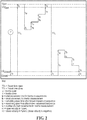
FIG. 2 is a calibration sequence for the climate control system; -
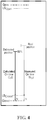
FIG. 3 is a baffle opening sequence for the climate control system; and -
FIG. 4 is an error correction sequence for the climate control system. - Corresponding reference characters indicate corresponding parts throughout the views of the drawings.
- The invention will now be described in the following detailed description with reference to the drawings, wherein preferred embodiments are described in detail to enable practice of the invention. Although the invention is described with reference to these specific preferred embodiments, it will be understood that the invention is not limited to these preferred embodiments.
- Referring to
FIG. 1 , a schematic of ananimal house 10 having aclimate control system 20 is shown. Theclimate control system 20 has a plurality of climate control sensing or input devices, such as temperature or static pressure probes, indicated at 21. Thesensing devices 21 may be located in different portions of theanimal house 10 so that climate information, such as temperature and static pressure, may be received for the different portions. Although threeinput devices 21 are shown, it will be understood that this is for purposes of illustrations only, and that additional or fewer input devices may be provided, as required. Theclimate control system 20 also has a plurality of climate control output devices, such as ventilation fans and/or heaters, indicated at 23 mounted in thebuilding 10. Although three heaters and ventilatingfans 23 are shown, it will be understood that this is for purposes of illustrations only, and that additional or fewer heaters and fans may be provided, as required. Various air inlets such as sidewall inlets, ceiling inlets and or tunnel inlets, indicated at 25, are used by theclimate control system 20 to control airflow into theanimal house 10. Although threeair inlets 25 are shown, it will be understood that this is for purposes of illustrations only, and that additional or fewer air inlets may be provided, as required. - The
climate control system 20 has amain control unit 27, which incorporates a suitable controller, such as a microprocessormain control unit 28, which receives input information from theinput devices 21 and regulates the operation of the ventilating fans andheaters 23 and theair inlets 25. - Each
air inlet 25 has a baffle or acurtain 30 used to change the area of the opening of theair inlet 25 and vary the amount of air coming into theanimal building 10. The position of thebaffle 30 determines the air flow and air speed for a fixed ventilation power of the ventilatingfans 23. Thebaffle 30 is positioned by anactuator 32 driven by amotor 34 controlled by thecontrol unit 27. In one embodiment, thebaffle 30 is moved by alinear actuator 32 driven byelectric motor 34. As would be understood by one skilled in the art, rotary motion of themotor 34 is converted to linear displacement of theactuator 32 and thus movement of thebaffle 30. Theair inlet 25 also has anopen limit switch 36 that is triggered when thebaffle 30 reaches the fully open position and aclosed limit switch 38 that is triggered when the baffle reaches the fully closed position. - In one embodiment, reading the current of the
motor 34 lets thecontrol unit 27 know every time alimit switch motor 34 current drops to zero. Desirably, thecontrol unit 27 causes an automatic error position reset with each such occurrence. In operation, theactuator 32 is moved many times every hour to reposition thebaffle 30 based on the inputs from theinput devices 21. Depending on weather and animal conditions, thebaffle 30 may be operated close to its fully extended or fully retracted position. Doing so, thebaffle 30hits limit switches control unit 27 can continue to apply power. By reading motor current through a sensor in line with the commanding relays, thecontrol unit 27 can determine when the actuator 32 hits aswitch actuator 32 hits alimit switch actuator 32 has not hit alimit switch control unit 27 to close (or open) theactuator 32 for a period of time equal to a full stroke (typically 60-120 seconds) even though it may reach position after only a few seconds. By reading motor current, reset time can be reduced to minimum and normal operation can resume as soon as motor current drops to zero. - Additionally, reading the current of the
motor 34 lets thecontrol unit 27 detect a malfunction of theair inlet 25 which may lead to animal discomfort or death. As an example, anactuator 32 that won't move in any direction (motor current stays at zero or is out of range) is defective and should backed-up by anotherair inlet 25 such as by opening wider anotherair inlet 25 or by using aseparate air inlet 25. - The
climate control system 20 uses a calibrated timed position method to adjust the position of thebaffle 30 of theair inlet 25. An advantage of using timed position control is the method does not require problematic position sensing devices to sense the position of thebaffle 30; thecontrol unit 27 just needs to be calibrated to mathematically relate cumulative Open Time with opening. One problem withclimate control systems 20 is that they drag at start and at stop leading to significant drift into opening calculations/estimates after 10-20 open and close cycles. According to one embodiment of the invention, theclimate control system 20 accounts for drag and overshoot at calibration and considers these dragging delays or inertias into the opening and closing calculations. The time before stopping to move is measured as the amount of time thebaffle 30 is still moving after thecontrol unit 27 has given the command to stop. Inertia of thebaffle 30 varies with load on theactuator 32. Thus, inertias are calculated for open and close operation at different position of thebaffle 30 as the load on theactuator 32 may vary. -
Figure 2 illustrates a method for calibrating theclimate control system 20. First, an automatic calibration step readsactuator motor 34 current to determine when the actuator 32 hits it's alimit switch - TTo = Travel time open
- TTc = Travel time close
- io = Inertia open
- ic = Inertia close
- ta = total movement time for inertia measurement
- tb = small movement for inertia measurement
- tc = remaining close time after known movement sequence
- to = remaining open time after known movement sequence
- n = number of small movements for inertia measurement
- vo = open velocity in %/sec.
- vc = close velocity in %/sec. (close velocity is negative)
- Using the measurements from the calibration sequence, inertia open (io) and inertia close (ic) values are calculated. In one embodiment, the inertia open (io) value is calculated using the following equation:

- In one embodiment, the inertia close (ic) value is calculated using the following equation:


- Set ta, tb and n
- Measure tc, to, TTo, TTc while executing sequence.
- With :
- ta = 10 sec
- tb = 2 sec
- n = 2
- The inertia open (io) value is calculated:

- The inertia close (ic) value is calculated:

- Desirably, inertia is measured in hundredth of a second for time-based inlets.
- Turning now to
Fig. 3 , to move abaffle 30 from an estimated or known position to another, the on time for theactuator 32 can be calculated as follows: - Key:
- Pi = Initial position
- Pf = Final position
- On time = Power on time needed for suited movement
- Turning now to
FIG. 4 , it is desired to calculate an accumulated error and reset. This section presents velocity correction theory and an application example. Relations presented here holds for a reset to closed position. - Let actuator A be at an estimated position of 50%, TTo = 120 sec, vc = 0,869%/sec, vo = 0,830%/sec.
- Last actuator movements were:
- no =32 movements in open direction
- nc = 18 movements in close direction
- If |Error| ≥ 1% and known last movements distribution, take the appropriate path shown in Table 1
Table 1 Reset type Error no : nc Open time Close time Relation Closed Positive no > nc Decrease = 1 Closed Positive no < nc Decrease Increase 2 Closed Negative no > nc Increase Decrease 3 Closed Negative no < nc = Decrease 4 Open Positive no > nc Increase Decrease 3 Open Positive no < nc = Decrease 4 Open Negative no > nc Decrease = 1 Open Negative no < nc Decrease Increase 2 ① 

② 


③ 


④ 

- Wherein increasing velocity shortens calculated movement times and decreasing velocity lengthens calculated movement times.
- The foregoing has broadly outlined some of the more pertinent aspects and features of the present invention. These should be construed to be merely illustrative of some of the more prominent features and applications of the invention. Other beneficial results can be obtained by applying the disclosed information in a different manner or by modifying the disclosed embodiments. Accordingly, other aspects and a more comprehensive understanding of the invention may be obtained by referring to the detailed description of the exemplary embodiments taken in conjunction with the accompanying drawings.



Claims (6)
- A climate control system (20) for an animal house (10), the climate control system comprising:a plurality of climate control input devices (21) configured to measure a climate input selected from the group of temperature and static pressure, wherein the plurality of input devices are for being located in different portions of the animal house;a plurality of climate control ventilation fans (23);at least one air inlet (25) used to control airflow into the animal house, the at least one air inlet having a baffle (30) configured to change the area of the opening of the air inlet to vary the amount of air coming into the animal building;at least one actuator (32) operably connected to the baffle of the at least one air inlet having a motor (34), the at least one actuator configured for selectively controllling the position of the baffle;an open limit switch (36) configured to be triggered when the baffle reaches a fully open position;a closed limit switch (38) configured to be triggered when the baffle reaches a fully closed position;a sensor configured to read the current applied to the motor; anda control unit (27, 28) configured to receive input information from the plurality of climate control input devices and regulate the operation of the ventilating fans,
characterized in that;
the control unit is configured to control operation of the actuator using calibrated timed position opening and closing commands to adjust the position of the baffle of the at least one air inlet,
the control unit further configured to account for dragging delays and overshoot inertias at calibration and consider these dragging delays or inertias in the calibrated timed position opening and closing commands;
said dragging delays and overshoot inertias being measured as the amount of time the baffle continues to move after the control unit has given a command to stop. - The climate control system of claim 1, wherein the inertias are calculated for open and close operation at different positions of the baffle.
- The climate control system of claim 2, wherein the control unit is configured to use a calibration step that reads actuator motor current to determine when the actuator hits one of the opening and closing limit switches, and an air inlet calibration sequence to determine an open travel time, a close travel time, an open inertia, a close inertia, an open velocity and a close velocity.
- The climate control system of claim 1, wherein the control unit is configured to move the baffle from an initial position to a final position by calculating a calculated power on time for the motor using an opening inertia value or a closing inertia value.
- A method for operating a baffle of an air inlet of an animal house with a motor, characterized in that the method uses timed inlet control and comprises the steps of:performing a calibration sequence to calculate opening velocity and opening inertia values and closing velocity and closing inertia values of said baffle, and;moving the baffle from an initial position to a final position by calculating a calculated power on time for the motor using the opening inertia or closing inertia values.
- The method of claim 5, further comprising calculating a real position error value by comparing the calculated on time for the motor and a measured on time for the motor and using the real position error value to calculate adjusted opening and closing velocity values.
Applications Claiming Priority (2)
| Application Number | Priority Date | Filing Date | Title |
|---|---|---|---|
| US201562170375P | 2015-06-03 | 2015-06-03 | |
| PCT/US2016/035661 WO2016196888A1 (en) | 2015-06-03 | 2016-06-03 | Animal house climate control system and method for operating an air inlet of the animal house using timed inlet control |
Publications (2)
| Publication Number | Publication Date |
|---|---|
| EP3302040A1 EP3302040A1 (en) | 2018-04-11 |
| EP3302040B1 true EP3302040B1 (en) | 2020-09-09 |
Family
ID=56555706
Family Applications (1)
| Application Number | Title | Priority Date | Filing Date |
|---|---|---|---|
| EP16745215.0A Active EP3302040B1 (en) | 2015-06-03 | 2016-06-03 | Animal house climate control system and method for operating an air inlet of the animal house using timed inlet control |
Country Status (5)
| Country | Link |
|---|---|
| US (1) | US11224198B2 (en) |
| EP (1) | EP3302040B1 (en) |
| CN (1) | CN107846864B (en) |
| MY (1) | MY190148A (en) |
| WO (1) | WO2016196888A1 (en) |
Families Citing this family (3)
| Publication number | Priority date | Publication date | Assignee | Title |
|---|---|---|---|---|
| CN110063261B (en) * | 2019-03-29 | 2021-05-28 | 广东南牧机械设备有限公司 | Wind window calibration method, device, system and breeding plant |
| CN213514317U (en) * | 2020-11-03 | 2021-06-22 | 厦门小羚科技有限责任公司 | A device with air purification, sterilization and temperature adjustment |
| WO2025149880A1 (en) * | 2024-01-08 | 2025-07-17 | Gsi Electronique Inc | Environmental control systems for livestock housings, and related systems and methods |
Family Cites Families (18)
| Publication number | Priority date | Publication date | Assignee | Title |
|---|---|---|---|---|
| US3752208A (en) * | 1971-04-12 | 1973-08-14 | Rixson Firemark | Closure operator |
| US3951336A (en) | 1974-08-28 | 1976-04-20 | Miller And Sons Structures, Inc. | Ventilation system for livestock housing |
| US4241871A (en) * | 1978-11-27 | 1980-12-30 | Newell Alfred T Iii | Apparatus and method for ventilation of animal enclosures |
| GB2238885B (en) | 1989-12-07 | 1993-09-08 | Mitsubishi Electric Corp | Air conditioning system |
| US5492082A (en) * | 1994-01-18 | 1996-02-20 | Ctb Inc. | Method and apparatus for controlling temperature within poultry houses and the like |
| NL1003308C2 (en) * | 1996-06-10 | 1997-12-17 | Vostermans B V A | Ventilation system, especially for application in the agricultural sector. |
| US6495981B2 (en) * | 2001-02-12 | 2002-12-17 | Johnson Controls Technology Company | Motorized actuator with a variable stall level |
| GB2393799B (en) * | 2002-08-22 | 2006-03-08 | Richard Gatley | Gas flow control systems |
| US8322683B2 (en) * | 2006-07-10 | 2012-12-04 | Hansen Corporation | Method and device for an actuator motor including a fan brake device |
| NZ592557A (en) * | 2007-05-29 | 2012-11-30 | Herd Homes Ltd | Animal shelter structure with a movable shade cloth |
| EA024463B8 (en) * | 2009-05-15 | 2017-01-30 | Нильс Сков Венг | Intelligent climate control in domestic animal stables |
| US9062893B2 (en) | 2011-05-13 | 2015-06-23 | Johnson Controls Technology Company | Speed adjustment of an actuator for an HVAC system |
| CN102511402A (en) * | 2011-12-29 | 2012-06-27 | 福建农林大学 | Intelligent microclimate control system for biological fermentation hog house |
| US8857376B2 (en) * | 2012-10-04 | 2014-10-14 | Dave Klocke | Hog confinement building ventilation system |
| CN103766224B (en) * | 2012-10-25 | 2017-06-20 | 湖南省农友机械集团农牧机械有限公司 | A kind of pig farm automation batch turning, excrement cleaning system |
| CN103940463A (en) * | 2013-05-06 | 2014-07-23 | 上海创塔电子科技有限公司 | Flowing dust pollution real-time monitoring and managing system and monitor instrument automatically-calibrating method thereof |
| ES2666071T3 (en) * | 2013-09-05 | 2018-04-30 | Aeris Soluciones De Control, S.L | Regulation method for an air conditioning system |
| KR20160050651A (en) * | 2014-10-30 | 2016-05-11 | 한국전자통신연구원 | System for managing livestock house and method therof |
-
2016
- 2016-06-03 US US15/580,245 patent/US11224198B2/en active Active
- 2016-06-03 CN CN201680041098.2A patent/CN107846864B/en active Active
- 2016-06-03 MY MYPI2017705172A patent/MY190148A/en unknown
- 2016-06-03 WO PCT/US2016/035661 patent/WO2016196888A1/en not_active Ceased
- 2016-06-03 EP EP16745215.0A patent/EP3302040B1/en active Active
Non-Patent Citations (1)
| Title |
|---|
| None * |
Also Published As
| Publication number | Publication date |
|---|---|
| EP3302040A1 (en) | 2018-04-11 |
| WO2016196888A1 (en) | 2016-12-08 |
| US20180160646A1 (en) | 2018-06-14 |
| MY190148A (en) | 2022-03-31 |
| CN107846864B (en) | 2022-01-28 |
| CN107846864A (en) | 2018-03-27 |
| US11224198B2 (en) | 2022-01-18 |
Similar Documents
| Publication | Publication Date | Title |
|---|---|---|
| EP2997430B1 (en) | Device and method for controlling the opening of a valve in an hvac system | |
| US9810462B2 (en) | Dehumidification using intermittent ventilation | |
| US11224198B2 (en) | Animal house climate control system and method for operating an air inlet of the animal house using timed inlet control | |
| EP2697572B1 (en) | Automatic function diagnosis system and method | |
| DE3726122C1 (en) | Method for controlling parameters of indoor air in a motor vehicle with an air conditioning system | |
| US9069363B2 (en) | Method and apparatus for regulating the temperature of a plurality of rooms in a building | |
| CN110243999B (en) | Calibration method of carbon dioxide sensor for fresh air system of air conditioner | |
| US20230009166A1 (en) | Indoor air quality for variable air volume system | |
| JP2021076348A (en) | Perimeter air conditioning system | |
| EP2508810A1 (en) | Ventilator module | |
| KR20200082804A (en) | System for pig management Ventilation control and its control method | |
| EP4119856A1 (en) | Indoor air quality for variable air volume system | |
| EP2527753A1 (en) | Device and method for regulating a fresh air supply for a device for cooling, heating and/or ventilating a building | |
| EP1158250B1 (en) | Apparatus for detecting the heat output of a radiator and regulating the room temperature | |
| US11779976B2 (en) | Application devices for cooling sections, having a second connection | |
| KR102476041B1 (en) | Ventilation fan automatic control system to prevent condensation inside the tunnel | |
| CN105138049A (en) | Constant temperature and humidity control method and apparatus in numerical control machine tool | |
| KR20210107247A (en) | A valve with a built-in temperature sensor and an automatic flow control hot water heating system using it | |
| DE10108852C1 (en) | Room temperature control | |
| CN110063261B (en) | Wind window calibration method, device, system and breeding plant | |
| KR102039434B1 (en) | Failure detecting device for infra-red sensor of a vehicle | |
| US20220178578A1 (en) | Method and a system for operating an air handling unit at effective static pressure | |
| DE102018208668A1 (en) | System for at least partial control of a temperature of an industrial robot and method for increasing the working accuracy of an industrial robot | |
| EP3225928A1 (en) | Device and method for controlling the indoor climate, and building equipped with same | |
| CN223077000U (en) | An air volume device for measuring system of range hood |
Legal Events
| Date | Code | Title | Description |
|---|---|---|---|
| STAA | Information on the status of an ep patent application or granted ep patent |
Free format text: STATUS: THE INTERNATIONAL PUBLICATION HAS BEEN MADE |
|
| PUAI | Public reference made under article 153(3) epc to a published international application that has entered the european phase |
Free format text: ORIGINAL CODE: 0009012 |
|
| STAA | Information on the status of an ep patent application or granted ep patent |
Free format text: STATUS: REQUEST FOR EXAMINATION WAS MADE |
|
| 17P | Request for examination filed |
Effective date: 20180103 |
|
| AK | Designated contracting states |
Kind code of ref document: A1 Designated state(s): AL AT BE BG CH CY CZ DE DK EE ES FI FR GB GR HR HU IE IS IT LI LT LU LV MC MK MT NL NO PL PT RO RS SE SI SK SM TR |
|
| AX | Request for extension of the european patent |
Extension state: BA ME |
|
| DAV | Request for validation of the european patent (deleted) | ||
| DAX | Request for extension of the european patent (deleted) | ||
| STAA | Information on the status of an ep patent application or granted ep patent |
Free format text: STATUS: EXAMINATION IS IN PROGRESS |
|
| 17Q | First examination report despatched |
Effective date: 20190723 |
|
| REG | Reference to a national code |
Ref country code: DE Ref legal event code: R079 Ref document number: 602016043700 Country of ref document: DE Free format text: PREVIOUS MAIN CLASS: A01K0001000000 Ipc: F24F0140400000 |
|
| GRAP | Despatch of communication of intention to grant a patent |
Free format text: ORIGINAL CODE: EPIDOSNIGR1 |
|
| STAA | Information on the status of an ep patent application or granted ep patent |
Free format text: STATUS: GRANT OF PATENT IS INTENDED |
|
| RIC1 | Information provided on ipc code assigned before grant |
Ipc: F24F 140/40 20180101AFI20200507BHEP Ipc: A01K 1/00 20060101ALI20200507BHEP |
|
| INTG | Intention to grant announced |
Effective date: 20200603 |
|
| GRAS | Grant fee paid |
Free format text: ORIGINAL CODE: EPIDOSNIGR3 |
|
| GRAA | (expected) grant |
Free format text: ORIGINAL CODE: 0009210 |
|
| STAA | Information on the status of an ep patent application or granted ep patent |
Free format text: STATUS: THE PATENT HAS BEEN GRANTED |
|
| AK | Designated contracting states |
Kind code of ref document: B1 Designated state(s): AL AT BE BG CH CY CZ DE DK EE ES FI FR GB GR HR HU IE IS IT LI LT LU LV MC MK MT NL NO PL PT RO RS SE SI SK SM TR |
|
| REG | Reference to a national code |
Ref country code: GB Ref legal event code: FG4D |
|
| REG | Reference to a national code |
Ref country code: AT Ref legal event code: REF Ref document number: 1312061 Country of ref document: AT Kind code of ref document: T Effective date: 20200915 Ref country code: CH Ref legal event code: EP |
|
| REG | Reference to a national code |
Ref country code: IE Ref legal event code: FG4D Ref country code: NL Ref legal event code: FP |
|
| REG | Reference to a national code |
Ref country code: DE Ref legal event code: R096 Ref document number: 602016043700 Country of ref document: DE |
|
| REG | Reference to a national code |
Ref country code: LT Ref legal event code: MG4D |
|
| PG25 | Lapsed in a contracting state [announced via postgrant information from national office to epo] |
Ref country code: NO Free format text: LAPSE BECAUSE OF FAILURE TO SUBMIT A TRANSLATION OF THE DESCRIPTION OR TO PAY THE FEE WITHIN THE PRESCRIBED TIME-LIMIT Effective date: 20201209 Ref country code: HR Free format text: LAPSE BECAUSE OF FAILURE TO SUBMIT A TRANSLATION OF THE DESCRIPTION OR TO PAY THE FEE WITHIN THE PRESCRIBED TIME-LIMIT Effective date: 20200909 Ref country code: SE Free format text: LAPSE BECAUSE OF FAILURE TO SUBMIT A TRANSLATION OF THE DESCRIPTION OR TO PAY THE FEE WITHIN THE PRESCRIBED TIME-LIMIT Effective date: 20200909 Ref country code: GR Free format text: LAPSE BECAUSE OF FAILURE TO SUBMIT A TRANSLATION OF THE DESCRIPTION OR TO PAY THE FEE WITHIN THE PRESCRIBED TIME-LIMIT Effective date: 20201210 Ref country code: FI Free format text: LAPSE BECAUSE OF FAILURE TO SUBMIT A TRANSLATION OF THE DESCRIPTION OR TO PAY THE FEE WITHIN THE PRESCRIBED TIME-LIMIT Effective date: 20200909 Ref country code: LT Free format text: LAPSE BECAUSE OF FAILURE TO SUBMIT A TRANSLATION OF THE DESCRIPTION OR TO PAY THE FEE WITHIN THE PRESCRIBED TIME-LIMIT Effective date: 20200909 Ref country code: BG Free format text: LAPSE BECAUSE OF FAILURE TO SUBMIT A TRANSLATION OF THE DESCRIPTION OR TO PAY THE FEE WITHIN THE PRESCRIBED TIME-LIMIT Effective date: 20201209 |
|
| REG | Reference to a national code |
Ref country code: AT Ref legal event code: MK05 Ref document number: 1312061 Country of ref document: AT Kind code of ref document: T Effective date: 20200909 |
|
| PG25 | Lapsed in a contracting state [announced via postgrant information from national office to epo] |
Ref country code: PL Free format text: LAPSE BECAUSE OF FAILURE TO SUBMIT A TRANSLATION OF THE DESCRIPTION OR TO PAY THE FEE WITHIN THE PRESCRIBED TIME-LIMIT Effective date: 20200909 Ref country code: LV Free format text: LAPSE BECAUSE OF FAILURE TO SUBMIT A TRANSLATION OF THE DESCRIPTION OR TO PAY THE FEE WITHIN THE PRESCRIBED TIME-LIMIT Effective date: 20200909 Ref country code: RS Free format text: LAPSE BECAUSE OF FAILURE TO SUBMIT A TRANSLATION OF THE DESCRIPTION OR TO PAY THE FEE WITHIN THE PRESCRIBED TIME-LIMIT Effective date: 20200909 |
|
| PG25 | Lapsed in a contracting state [announced via postgrant information from national office to epo] |
Ref country code: EE Free format text: LAPSE BECAUSE OF FAILURE TO SUBMIT A TRANSLATION OF THE DESCRIPTION OR TO PAY THE FEE WITHIN THE PRESCRIBED TIME-LIMIT Effective date: 20200909 Ref country code: CZ Free format text: LAPSE BECAUSE OF FAILURE TO SUBMIT A TRANSLATION OF THE DESCRIPTION OR TO PAY THE FEE WITHIN THE PRESCRIBED TIME-LIMIT Effective date: 20200909 Ref country code: RO Free format text: LAPSE BECAUSE OF FAILURE TO SUBMIT A TRANSLATION OF THE DESCRIPTION OR TO PAY THE FEE WITHIN THE PRESCRIBED TIME-LIMIT Effective date: 20200909 Ref country code: SM Free format text: LAPSE BECAUSE OF FAILURE TO SUBMIT A TRANSLATION OF THE DESCRIPTION OR TO PAY THE FEE WITHIN THE PRESCRIBED TIME-LIMIT Effective date: 20200909 Ref country code: PT Free format text: LAPSE BECAUSE OF FAILURE TO SUBMIT A TRANSLATION OF THE DESCRIPTION OR TO PAY THE FEE WITHIN THE PRESCRIBED TIME-LIMIT Effective date: 20210111 |
|
| PG25 | Lapsed in a contracting state [announced via postgrant information from national office to epo] |
Ref country code: AL Free format text: LAPSE BECAUSE OF FAILURE TO SUBMIT A TRANSLATION OF THE DESCRIPTION OR TO PAY THE FEE WITHIN THE PRESCRIBED TIME-LIMIT Effective date: 20200909 Ref country code: AT Free format text: LAPSE BECAUSE OF FAILURE TO SUBMIT A TRANSLATION OF THE DESCRIPTION OR TO PAY THE FEE WITHIN THE PRESCRIBED TIME-LIMIT Effective date: 20200909 Ref country code: ES Free format text: LAPSE BECAUSE OF FAILURE TO SUBMIT A TRANSLATION OF THE DESCRIPTION OR TO PAY THE FEE WITHIN THE PRESCRIBED TIME-LIMIT Effective date: 20200909 Ref country code: IS Free format text: LAPSE BECAUSE OF FAILURE TO SUBMIT A TRANSLATION OF THE DESCRIPTION OR TO PAY THE FEE WITHIN THE PRESCRIBED TIME-LIMIT Effective date: 20210109 |
|
| REG | Reference to a national code |
Ref country code: DE Ref legal event code: R097 Ref document number: 602016043700 Country of ref document: DE |
|
| PG25 | Lapsed in a contracting state [announced via postgrant information from national office to epo] |
Ref country code: SK Free format text: LAPSE BECAUSE OF FAILURE TO SUBMIT A TRANSLATION OF THE DESCRIPTION OR TO PAY THE FEE WITHIN THE PRESCRIBED TIME-LIMIT Effective date: 20200909 |
|
| PLBE | No opposition filed within time limit |
Free format text: ORIGINAL CODE: 0009261 |
|
| STAA | Information on the status of an ep patent application or granted ep patent |
Free format text: STATUS: NO OPPOSITION FILED WITHIN TIME LIMIT |
|
| 26N | No opposition filed |
Effective date: 20210610 |
|
| PG25 | Lapsed in a contracting state [announced via postgrant information from national office to epo] |
Ref country code: DK Free format text: LAPSE BECAUSE OF FAILURE TO SUBMIT A TRANSLATION OF THE DESCRIPTION OR TO PAY THE FEE WITHIN THE PRESCRIBED TIME-LIMIT Effective date: 20200909 Ref country code: SI Free format text: LAPSE BECAUSE OF FAILURE TO SUBMIT A TRANSLATION OF THE DESCRIPTION OR TO PAY THE FEE WITHIN THE PRESCRIBED TIME-LIMIT Effective date: 20200909 |
|
| PGFP | Annual fee paid to national office [announced via postgrant information from national office to epo] |
Ref country code: BE Payment date: 20210618 Year of fee payment: 6 |
|
| PG25 | Lapsed in a contracting state [announced via postgrant information from national office to epo] |
Ref country code: MC Free format text: LAPSE BECAUSE OF FAILURE TO SUBMIT A TRANSLATION OF THE DESCRIPTION OR TO PAY THE FEE WITHIN THE PRESCRIBED TIME-LIMIT Effective date: 20200909 |
|
| REG | Reference to a national code |
Ref country code: CH Ref legal event code: PL |
|
| GBPC | Gb: european patent ceased through non-payment of renewal fee |
Effective date: 20210603 |
|
| PG25 | Lapsed in a contracting state [announced via postgrant information from national office to epo] |
Ref country code: LU Free format text: LAPSE BECAUSE OF NON-PAYMENT OF DUE FEES Effective date: 20210603 |
|
| PG25 | Lapsed in a contracting state [announced via postgrant information from national office to epo] |
Ref country code: LI Free format text: LAPSE BECAUSE OF NON-PAYMENT OF DUE FEES Effective date: 20210630 Ref country code: IE Free format text: LAPSE BECAUSE OF NON-PAYMENT OF DUE FEES Effective date: 20210603 Ref country code: GB Free format text: LAPSE BECAUSE OF NON-PAYMENT OF DUE FEES Effective date: 20210603 Ref country code: CH Free format text: LAPSE BECAUSE OF NON-PAYMENT OF DUE FEES Effective date: 20210630 |
|
| REG | Reference to a national code |
Ref country code: BE Ref legal event code: MM Effective date: 20220630 |
|
| PG25 | Lapsed in a contracting state [announced via postgrant information from national office to epo] |
Ref country code: HU Free format text: LAPSE BECAUSE OF FAILURE TO SUBMIT A TRANSLATION OF THE DESCRIPTION OR TO PAY THE FEE WITHIN THE PRESCRIBED TIME-LIMIT; INVALID AB INITIO Effective date: 20160603 Ref country code: BE Free format text: LAPSE BECAUSE OF NON-PAYMENT OF DUE FEES Effective date: 20220630 |
|
| P01 | Opt-out of the competence of the unified patent court (upc) registered |
Effective date: 20230518 |
|
| PG25 | Lapsed in a contracting state [announced via postgrant information from national office to epo] |
Ref country code: CY Free format text: LAPSE BECAUSE OF FAILURE TO SUBMIT A TRANSLATION OF THE DESCRIPTION OR TO PAY THE FEE WITHIN THE PRESCRIBED TIME-LIMIT Effective date: 20200909 |
|
| PG25 | Lapsed in a contracting state [announced via postgrant information from national office to epo] |
Ref country code: MK Free format text: LAPSE BECAUSE OF FAILURE TO SUBMIT A TRANSLATION OF THE DESCRIPTION OR TO PAY THE FEE WITHIN THE PRESCRIBED TIME-LIMIT Effective date: 20200909 |
|
| PG25 | Lapsed in a contracting state [announced via postgrant information from national office to epo] |
Ref country code: MT Free format text: LAPSE BECAUSE OF FAILURE TO SUBMIT A TRANSLATION OF THE DESCRIPTION OR TO PAY THE FEE WITHIN THE PRESCRIBED TIME-LIMIT Effective date: 20200909 |
|
| PGFP | Annual fee paid to national office [announced via postgrant information from national office to epo] |
Ref country code: DE Payment date: 20250627 Year of fee payment: 10 |
|
| PGFP | Annual fee paid to national office [announced via postgrant information from national office to epo] |
Ref country code: NL Payment date: 20250626 Year of fee payment: 10 |
|
| PGFP | Annual fee paid to national office [announced via postgrant information from national office to epo] |
Ref country code: FR Payment date: 20250625 Year of fee payment: 10 |
|
| PGFP | Annual fee paid to national office [announced via postgrant information from national office to epo] |
Ref country code: IT Payment date: 20250619 Year of fee payment: 10 |
|
| PG25 | Lapsed in a contracting state [announced via postgrant information from national office to epo] |
Ref country code: TR Free format text: LAPSE BECAUSE OF FAILURE TO SUBMIT A TRANSLATION OF THE DESCRIPTION OR TO PAY THE FEE WITHIN THE PRESCRIBED TIME-LIMIT Effective date: 20200909 |