EP3301748A1 - Battery - Google Patents
Battery Download PDFInfo
- Publication number
- EP3301748A1 EP3301748A1 EP17770491.3A EP17770491A EP3301748A1 EP 3301748 A1 EP3301748 A1 EP 3301748A1 EP 17770491 A EP17770491 A EP 17770491A EP 3301748 A1 EP3301748 A1 EP 3301748A1
- Authority
- EP
- European Patent Office
- Prior art keywords
- circumference
- battery
- circular arcs
- electronic device
- closed curve
- Prior art date
- Legal status (The legal status is an assumption and is not a legal conclusion. Google has not performed a legal analysis and makes no representation as to the accuracy of the status listed.)
- Granted
Links
Images

Classifications
-
- H—ELECTRICITY
- H01—ELECTRIC ELEMENTS
- H01M—PROCESSES OR MEANS, e.g. BATTERIES, FOR THE DIRECT CONVERSION OF CHEMICAL ENERGY INTO ELECTRICAL ENERGY
- H01M10/00—Secondary cells; Manufacture thereof
- H01M10/05—Accumulators with non-aqueous electrolyte
- H01M10/058—Construction or manufacture
-
- H—ELECTRICITY
- H01—ELECTRIC ELEMENTS
- H01M—PROCESSES OR MEANS, e.g. BATTERIES, FOR THE DIRECT CONVERSION OF CHEMICAL ENERGY INTO ELECTRICAL ENERGY
- H01M10/00—Secondary cells; Manufacture thereof
- H01M10/05—Accumulators with non-aqueous electrolyte
- H01M10/052—Li-accumulators
-
- H—ELECTRICITY
- H01—ELECTRIC ELEMENTS
- H01M—PROCESSES OR MEANS, e.g. BATTERIES, FOR THE DIRECT CONVERSION OF CHEMICAL ENERGY INTO ELECTRICAL ENERGY
- H01M50/00—Constructional details or processes of manufacture of the non-active parts of electrochemical cells other than fuel cells, e.g. hybrid cells
- H01M50/10—Primary casings; Jackets or wrappings
- H01M50/102—Primary casings; Jackets or wrappings characterised by their shape or physical structure
- H01M50/107—Primary casings; Jackets or wrappings characterised by their shape or physical structure having curved cross-section, e.g. round or elliptic
-
- H—ELECTRICITY
- H01—ELECTRIC ELEMENTS
- H01M—PROCESSES OR MEANS, e.g. BATTERIES, FOR THE DIRECT CONVERSION OF CHEMICAL ENERGY INTO ELECTRICAL ENERGY
- H01M2220/00—Batteries for particular applications
- H01M2220/30—Batteries in portable systems, e.g. mobile phone, laptop
-
- Y—GENERAL TAGGING OF NEW TECHNOLOGICAL DEVELOPMENTS; GENERAL TAGGING OF CROSS-SECTIONAL TECHNOLOGIES SPANNING OVER SEVERAL SECTIONS OF THE IPC; TECHNICAL SUBJECTS COVERED BY FORMER USPC CROSS-REFERENCE ART COLLECTIONS [XRACs] AND DIGESTS
- Y02—TECHNOLOGIES OR APPLICATIONS FOR MITIGATION OR ADAPTATION AGAINST CLIMATE CHANGE
- Y02E—REDUCTION OF GREENHOUSE GAS [GHG] EMISSIONS, RELATED TO ENERGY GENERATION, TRANSMISSION OR DISTRIBUTION
- Y02E60/00—Enabling technologies; Technologies with a potential or indirect contribution to GHG emissions mitigation
- Y02E60/10—Energy storage using batteries
-
- Y—GENERAL TAGGING OF NEW TECHNOLOGICAL DEVELOPMENTS; GENERAL TAGGING OF CROSS-SECTIONAL TECHNOLOGIES SPANNING OVER SEVERAL SECTIONS OF THE IPC; TECHNICAL SUBJECTS COVERED BY FORMER USPC CROSS-REFERENCE ART COLLECTIONS [XRACs] AND DIGESTS
- Y02—TECHNOLOGIES OR APPLICATIONS FOR MITIGATION OR ADAPTATION AGAINST CLIMATE CHANGE
- Y02P—CLIMATE CHANGE MITIGATION TECHNOLOGIES IN THE PRODUCTION OR PROCESSING OF GOODS
- Y02P70/00—Climate change mitigation technologies in the production process for final industrial or consumer products
- Y02P70/50—Manufacturing or production processes characterised by the final manufactured product
Definitions
- the present invention relates to a battery, and more particularly, to a shape of a battery.
- the battery may be diversely changed in shape according to characteristics of the electronic device on which the battery is mounted, and particularly, electronic devices such as mobile phones usable in hand-held manner are often manufactured to have curved surfaces so as to improve user's grip feeling. Accordingly, the battery mounted within the electronic device may also be manufactured to have a curved surface. Therefore, to improve the grip feeling of the electronic device, the battery mounted within the electronic device is also required to be changed in shape so as to be suitable for the electronic device.
- an object of the present invention is to improve grip feeling of an electronic device and promote miniaturization of the electronic device by optimizing a shape of a battery.
- a battery including: a first surface having a circumference of a closed curve having a curve; a second surface having a circumference of a closed curve having a curve ; and a volume portion configured to connect the first surface to the second surface and defining a volume, wherein at least one of the first surface and the second surface has a circumference of the closed curve defined by connecting ends of each of two curves curved in the same direction to each other, and the first surface has an area different from that of the second surface.
- Each of the curves may be a circular arc.
- the two circular arcs may have the same curvature center.
- the two circular arcs may have the same central angle.
- Each of the first surface and the second surface may have a circumference of the closed curve defined by connecting ends of each of two circular arcs curved in the same direction to each other, and at least one curvature radius of two circular arcs constituting the circumference of the first surface may be different from each curvature radius of two circular arcs constituting the circumference of the second surface.
- All curvature radii of the two circular arcs constituting the circumference of the first surface may be less than each curvature radius of the two circular arcs constituting the circumference of the second surface.
- the first surface may be parallel to the second surface, and each of the first surface and the second surface may have a circumference of the closed curve defined by connecting ends of each of two circular arcs having the same curvature center and the same central angle to each other when the first surface and the second surface are vertically viewed.
- the volume portion may be defined by connecting the circumference of the first surface to the circumference of the second surface in a straight line.
- the electronic device to which the battery is mounted may be improved in grip feeling and promoted in miniaturization by optimizing the shape of the battery.
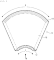
- FIG. 1 is a view illustrating a shape of a battery according to an embodiment of the present invention.
- the present invention is provided with a battery 10.
- the battery according to the present invention may be a secondary battery. Also, the battery according to the present invention may be a battery mounted on an electronic device.
- the battery 10 includes a first surface 12 defining a bottom surface of the battery 10, a second surface 14 defining a top surface of the battery 10, and a volume portion 16 connecting the first surface 12 to the second surface 14 and defining a volume of the battery 10. That is, the first surface 12 and the second surface 14 are defined at both ends of the volume portion 16.
- the volume portion 16 may connect a circumference of the first surface 12 to a circumference of the second surface 14.
- the expressions of the 'top surface' or the 'bottom surface' in the specification are merely named according to a direction of the battery illustrated in the drawings of the specification, and should not be construed as a direction of the battery in a state in which the battery is used by being mounted on the electronic device and the like.
- each of the first surface 12 and the second surface 14 has a circumference of a closed curve.
- FIGS. 2 and 3 are views illustrating examples of the first surface and the second surface of the battery according to an embodiment of the present invention, respectively. Referring to FIGS. 2 and 3 , for example, at least one of the first surface 12 and the second surface 14 may have a circumference of a closed curve defined by connecting ends of each of two curves curved in the same direction to each other. Also, according to the present invention, the first surface 12 may have an area different from that of the second surface 14. When the first surface 12 has the area different from that of the second surface 14, the first surface 12 may mean a surface having a smaller area, and the second surface 14 may mean a surface having a larger area.
- the first surface 12 or the second surface 14 has the circumference of the closed curve defined by connecting ends of each of two curves curved in the same direction to each other, at least one of the two curves may be a circular arc.
- all the two curves defining a portion of the circumference of the first surface 12 or the second surface 14 are illustrated to be circular arcs. That is, FIG. 2 illustrates an example in which the two curves defining the portion of the circumference of the first surface 12 respectively have circular arc shapes with the curvature radii r1 and r2, and FIG.
- FIG. 3 illustrates an example in which the two curves defining the portion of the circumference of the second surface 14 respectively have circular arc shapes with the curvature radii R1 and R2.
- the present invention is not limited to the above-described circular arc, but an only portion of the two curves defining a portion of the circumference of the first surface or the second surface may be the circular arc.
- the two circular arcs may have the same curvature center C as illustrated in FIGS. 2 and 3 . That is, FIGS. 2 and 3 illustrate an example in which the two circular arcs respectively defining the portions of the circumference of the first surface 12 or the second surface 14 have the same curvature center C1 or C2.
- FIGS. 2 and 3 illustrates an example in which the two circular arcs respectively defining the portions of the circumference of the first surface 12 or the second surface 14 have the same central angle ⁇ or ⁇ '.
- circular arcs defining the portions of the circumferences of the first surface 12 and the second surface 14 respectively have of curvature radii r1, r2, R1, and R2, a relationship in size between the curvature radii may be defined as follows.
- At least one curvature radius of the two circular arcs constituting the circumference of the first surface 12 may be different from all the curvature radii of the two circular arcs constituting the circumference of the second surface 14. That is, referring to FIGS. 2 and 3 , at least one of the curvature radii r1 and r2 may be different from all curvature radii R1 and R2. Similarly, at least one curvature radius of the two circular arcs constituting the circumference of the second surface 14 may be different from all the curvature radii of the two circular arcs constituting the circumference of the first surface 12. That is, referring to FIGS. 2 and 3 , at least one of the curvature radii R1 and R2 may be different from all curvature radii r1 and r2.
- all curvature radii of the two circular arcs constituting the circumference of the first surface 12 may less than each curvature radius of the two circular arcs constituting the circumference of the second surface 14. That is, referring to FIGS. 2 and 3 , the curvature radii r1 and r2 may be less than the curvature radii R1 and R2.
- first surface 12 and the second surface 14 of the battery 10 may be parallel to each other.
- two circular arcs constituting each circumference of the closed curves of the first surface 12 and the second surface 14 may have the same central angle and the same point as the curvature center.
- the volume portion 16 connects the first surface 12 to the second surface 14 and defines a volume of the battery 10.
- the volume portion 16 may connect the first surface 12 to the second surface 14 in a straight line.
- the volume portion 16 may connect the circumference of the first surface 12 to the circumference of the second surface 14 in the straight line as illustrated in FIG. 1 .
- the battery 10 according to the embodiment of the present invention may have a portion of a circular cone shape. That is, as illustrated in FIGS. 1 to 3 , when the first surface 12 and the second surface 14 are parallel to each other, and the volume portion 16 connects the circumference of the first surface 12 to the circumference of the second surface 14 in the straight line while the two circular arcs constituting each circumference of the closed curves of the first surface 12 and the second surface 14 (that is, total four circular arcs) have the same central angle and the same point as the curvature radius, the battery according to the embodiment of the present invention may have a shape, which is defined by a portion of a circumference of the remaining portion (a kind of truncated cone) after cutting an upper portion of the circular cone. Alternatively, the battery 10 may have a portion of a cone shape.
- the electronic device In case of an electronic device mainly used in a state of being held by a hand of a user, the electronic device is often manufactured to have a curved surface so as to improve grip feeling of the electronic device in use (there are various forms such as a loudspeaker). Therefore, a battery mounted on the electronic device may be also manufactured to have a curved surface.
- the human hand may have different curvature radii at respective sections in view of the structure of the human body.
- the improvement of the grip feeling for the electronic device may be limited in degree. Therefore, it is preferable that the electronic device has curvature radii different from each other on top and bottom curved surfaces thereof to maximize the grip feeling thereof (for example, particularly required for an electronic device such as a loudspeaker). Therefore, it is preferable that the battery mounted on the electronic device has curvature radii different from each other on top and bottom curved surfaces thereof.
- the battery according to the present invention have the above-described shape, since the battery has the curved surface on the whole and have different curvature radii on the top and bottom surfaces thereof, the battery may be effectively mounted on the electronic device (the loudspeaker and the like) having different curvature radii at the top and bottom curved surfaces.
- the grip feeling of the electronic device is improved, and also the internal space required inside the electronic device is minimized due to a match between space within the electronic device for disposing the battery and the shape of the battery, and thus technical effect of promoting miniaturization of the electronic device is present.
Landscapes
- Chemical & Material Sciences (AREA)
- Chemical Kinetics & Catalysis (AREA)
- Electrochemistry (AREA)
- General Chemical & Material Sciences (AREA)
- Engineering & Computer Science (AREA)
- Manufacturing & Machinery (AREA)
- Sealing Battery Cases Or Jackets (AREA)
- Battery Mounting, Suspending (AREA)
- Secondary Cells (AREA)
Abstract
Description
- The present application claims the benefit of the priority of Korean Patent Application No.
10-2016-0035196, filed on March 24, 2016 - The present invention relates to a battery, and more particularly, to a shape of a battery.
- In recent years, as various electronic devices have diverse shapes when compared to the existing electronic devices, diversity in shape of batteries provided with the electronic devices also becomes important. That is, when it is intend to install a typical battery having a simple shape in an electronic device having various shapes different from those of the existing electronic device, an empty space may be generated within the electronic device due to mismatch between the shape of the battery and the internal space of the electronic device, in which the battery is accommodated. As a result, this becomes a retrogressive factor against customer demands in recent trends in which the electronic device is miniaturized in size so as to facilitate portability and mobility of the electronic device. Thus, studies on development of a battery having various shapes are being conducted continuously.
The battery may be diversely changed in shape according to characteristics of the electronic device on which the battery is mounted, and particularly, electronic devices such as mobile phones usable in hand-held manner are often manufactured to have curved surfaces so as to improve user's grip feeling. Accordingly, the battery mounted within the electronic device may also be manufactured to have a curved surface. Therefore, to improve the grip feeling of the electronic device, the battery mounted within the electronic device is also required to be changed in shape so as to be suitable for the electronic device. - Thus, an object of the present invention is to improve grip feeling of an electronic device and promote miniaturization of the electronic device by optimizing a shape of a battery.
- According to one aspect of the present invention in order to achieve the above-described object, a battery is provided, the battery including: a first surface having a circumference of a closed curve having a curve; a second surface having a circumference of a closed curve having a curve ; and a volume portion configured to connect the first surface to the second surface and defining a volume, wherein at least one of the first surface and the second surface has a circumference of the closed curve defined by connecting ends of each of two curves curved in the same direction to each other, and the first surface has an area different from that of the second surface.
- Each of the curves may be a circular arc.
- The two circular arcs may have the same curvature center.
- The two circular arcs may have the same central angle.
- Each of the first surface and the second surface may have a circumference of the closed curve defined by connecting ends of each of two circular arcs curved in the same direction to each other, and at least one curvature radius of two circular arcs constituting the circumference of the first surface may be different from each curvature radius of two circular arcs constituting the circumference of the second surface.
- All curvature radii of the two circular arcs constituting the circumference of the first surface may be less than each curvature radius of the two circular arcs constituting the circumference of the second surface.
- The first surface may be parallel to the second surface, and each of the first surface and the second surface may have a circumference of the closed curve defined by connecting ends of each of two circular arcs having the same curvature center and the same central angle to each other when the first surface and the second surface are vertically viewed.
- The volume portion may be defined by connecting the circumference of the first surface to the circumference of the second surface in a straight line.
- According to the present invention, the electronic device to which the battery is mounted may be improved in grip feeling and promoted in miniaturization by optimizing the shape of the battery.
-
-
FIG. 1 is a view illustrating a shape of a battery according to an embodiment of the present invention. -
FIGS. 2 and 3 are views illustrating examples of a first surface and a second surface of the battery according to an embodiment of the present invention, respectively. - Hereinafter, an embodiment of the present invention will be described with reference to the accompanying drawings. However, the present invention is not limited or restricted to the following embodiment.
-
FIG. 1 is a view illustrating a shape of a battery according to an embodiment of the present invention. - Referring to
FIG. 1 , the present invention is provided with abattery 10. The battery according to the present invention may be a secondary battery. Also, the battery according to the present invention may be a battery mounted on an electronic device. - The
battery 10 includes afirst surface 12 defining a bottom surface of thebattery 10, asecond surface 14 defining a top surface of thebattery 10, and avolume portion 16 connecting thefirst surface 12 to thesecond surface 14 and defining a volume of thebattery 10. That is, thefirst surface 12 and thesecond surface 14 are defined at both ends of thevolume portion 16. Here, thevolume portion 16 may connect a circumference of thefirst surface 12 to a circumference of thesecond surface 14. - Here, the expressions of the 'top surface' or the 'bottom surface' in the specification are merely named according to a direction of the battery illustrated in the drawings of the specification, and should not be construed as a direction of the battery in a state in which the battery is used by being mounted on the electronic device and the like.
- Also, each of the
first surface 12 and thesecond surface 14 has a circumference of a closed curve.FIGS. 2 and 3 are views illustrating examples of the first surface and the second surface of the battery according to an embodiment of the present invention, respectively. Referring toFIGS. 2 and 3 , for example, at least one of thefirst surface 12 and thesecond surface 14 may have a circumference of a closed curve defined by connecting ends of each of two curves curved in the same direction to each other. Also, according to the present invention, thefirst surface 12 may have an area different from that of thesecond surface 14. When thefirst surface 12 has the area different from that of thesecond surface 14, thefirst surface 12 may mean a surface having a smaller area, and thesecond surface 14 may mean a surface having a larger area. - Also, when the
first surface 12 or thesecond surface 14 has the circumference of the closed curve defined by connecting ends of each of two curves curved in the same direction to each other, at least one of the two curves may be a circular arc. InFIGS. 2 and 3 , all the two curves defining a portion of the circumference of thefirst surface 12 or thesecond surface 14 are illustrated to be circular arcs. That is,FIG. 2 illustrates an example in which the two curves defining the portion of the circumference of thefirst surface 12 respectively have circular arc shapes with the curvature radii r1 and r2, andFIG. 3 illustrates an example in which the two curves defining the portion of the circumference of thesecond surface 14 respectively have circular arc shapes with the curvature radii R1 and R2. However, the present invention is not limited to the above-described circular arc, but an only portion of the two curves defining a portion of the circumference of the first surface or the second surface may be the circular arc. - When all the two curves defining the portion of the circumference of the
first surface 12 or thesecond surface 14 are circular arcs, the two circular arcs may have the same curvature center C as illustrated inFIGS. 2 and 3 . That is,FIGS. 2 and 3 illustrate an example in which the two circular arcs respectively defining the portions of the circumference of thefirst surface 12 or thesecond surface 14 have the same curvature center C1 or C2. - Also, when the two curves defining the portion of the circumference of the
first surface 12 or thesecond surface 14 are circular arcs, and the circular arcs have the same curvature center C, these two circular arcs may have the same central angle.FIGS. 2 and 3 illustrates an example in which the two circular arcs respectively defining the portions of the circumference of thefirst surface 12 or thesecond surface 14 have the same central angle θ or θ'. - Also, as illustrated in
FIGS. 2 and 3 , circular arcs defining the portions of the circumferences of thefirst surface 12 and thesecond surface 14 respectively have of curvature radii r1, r2, R1, and R2, a relationship in size between the curvature radii may be defined as follows. - At least one curvature radius of the two circular arcs constituting the circumference of the
first surface 12 may be different from all the curvature radii of the two circular arcs constituting the circumference of thesecond surface 14. That is, referring toFIGS. 2 and 3 , at least one of the curvature radii r1 and r2 may be different from all curvature radii R1 and R2. Similarly, at least one curvature radius of the two circular arcs constituting the circumference of thesecond surface 14 may be different from all the curvature radii of the two circular arcs constituting the circumference of thefirst surface 12. That is, referring toFIGS. 2 and 3 , at least one of the curvature radii R1 and R2 may be different from all curvature radii r1 and r2. - Also, when the
first surface 12 has the area less than that of thesecond surface 14, all curvature radii of the two circular arcs constituting the circumference of thefirst surface 12 may less than each curvature radius of the two circular arcs constituting the circumference of thesecond surface 14. That is, referring toFIGS. 2 and 3 , the curvature radii r1 and r2 may be less than the curvature radii R1 and R2. - Also, the
first surface 12 and thesecond surface 14 of thebattery 10 according to the embodiment of the present invention may be parallel to each other. Also, when thefirst surface 12 and thesecond surface 14 are vertically viewed (for example, when the battery is viewed in a direction P with respect toFIG. 2 ), two circular arcs constituting each circumference of the closed curves of thefirst surface 12 and the second surface 14 (that is, total four circular arcs) may have the same central angle and the same point as the curvature center. Also, thefirst surface 12 may has the same central angle as the second surface 14 (i.e., θ=θ'). - Also, as described above, the
volume portion 16 connects thefirst surface 12 to thesecond surface 14 and defines a volume of thebattery 10. Here, thevolume portion 16 may connect thefirst surface 12 to thesecond surface 14 in a straight line. For example, thevolume portion 16 may connect the circumference of thefirst surface 12 to the circumference of thesecond surface 14 in the straight line as illustrated inFIG. 1 . - Also, the
battery 10 according to the embodiment of the present invention may have a portion of a circular cone shape. That is, as illustrated inFIGS. 1 to 3 , when thefirst surface 12 and thesecond surface 14 are parallel to each other, and thevolume portion 16 connects the circumference of thefirst surface 12 to the circumference of thesecond surface 14 in the straight line while the two circular arcs constituting each circumference of the closed curves of thefirst surface 12 and the second surface 14 (that is, total four circular arcs) have the same central angle and the same point as the curvature radius, the battery according to the embodiment of the present invention may have a shape, which is defined by a portion of a circumference of the remaining portion (a kind of truncated cone) after cutting an upper portion of the circular cone. Alternatively, thebattery 10 may have a portion of a cone shape. - In case of an electronic device mainly used in a state of being held by a hand of a user, the electronic device is often manufactured to have a curved surface so as to improve grip feeling of the electronic device in use (there are various forms such as a loudspeaker). Therefore, a battery mounted on the electronic device may be also manufactured to have a curved surface.
- However, the human hand may have different curvature radii at respective sections in view of the structure of the human body. Thus, if curved surfaces disposed at upper and lower sides of the electronic device have the same curvature radius when the electronic device has a curved surface, the improvement of the grip feeling for the electronic device may be limited in degree. Therefore, it is preferable that the electronic device has curvature radii different from each other on top and bottom curved surfaces thereof to maximize the grip feeling thereof (for example, particularly required for an electronic device such as a loudspeaker). Therefore, it is preferable that the battery mounted on the electronic device has curvature radii different from each other on top and bottom curved surfaces thereof.
- Thus, when the battery according to the present invention have the above-described shape, since the battery has the curved surface on the whole and have different curvature radii on the top and bottom surfaces thereof, the battery may be effectively mounted on the electronic device (the loudspeaker and the like) having different curvature radii at the top and bottom curved surfaces. Thus, the grip feeling of the electronic device is improved, and also the internal space required inside the electronic device is minimized due to a match between space within the electronic device for disposing the battery and the shape of the battery, and thus technical effect of promoting miniaturization of the electronic device is present.
Claims (8)
- A battery comprising:a first surface having a circumference of a closed curve having a curve;a second surface having a circumference of a closed curve having a curve; anda volume portion configured to connect the first surface to the second surface and defining a volume,wherein at least one of the first surface and the second surface has a circumference of the closed curve defined by connecting ends of each of two curves curved in the same direction to each other, andthe first surface has an area different from that of the second surface.
- The battery of claim 1, wherein each of the curves is a circular arc.
- The battery of claim 2, wherein the two circular arcs has the same curvature center.
- The battery of claim 3, wherein the two circular arcs has the same central angle.
- The battery of claim 1, wherein each of the first surface and the second surface has a circumference of the closed curve defined by connecting ends of each of two circular arcs curved in the same direction to each other, and
at least one curvature radius of two circular arcs constituting the circumference of the first surface is different from each curvature radius of two circular arcs constituting the circumference of the second surface. - The battery of claim 5, wherein all curvature radii of the two circular arcs constituting the circumference of the first surface are less than each curvature radius of the two circular arcs constituting the circumference of the second surface.
- The battery of claim 1, wherein the first surface is parallel to the second surface, and
each of the first surface and the second surface has a circumference of the closed curve defined by connecting ends of each of two circular arcs having the same curvature center and the same central angle to each other when the first surface and the second surface are vertically viewed. - The battery of claim 1, wherein the volume portion is defined by connecting the circumference of the first surface to the circumference of the second surface in a straight line.
Applications Claiming Priority (2)
| Application Number | Priority Date | Filing Date | Title |
|---|---|---|---|
| KR1020160035196A KR102094463B1 (en) | 2016-03-24 | 2016-03-24 | Battery |
| PCT/KR2017/001861 WO2017164520A1 (en) | 2016-03-24 | 2017-02-20 | Battery |
Publications (3)
| Publication Number | Publication Date |
|---|---|
| EP3301748A1 true EP3301748A1 (en) | 2018-04-04 |
| EP3301748A4 EP3301748A4 (en) | 2018-05-30 |
| EP3301748B1 EP3301748B1 (en) | 2020-06-03 |
Family
ID=59900593
Family Applications (1)
| Application Number | Title | Priority Date | Filing Date |
|---|---|---|---|
| EP17770491.3A Active EP3301748B1 (en) | 2016-03-24 | 2017-02-20 | Battery |
Country Status (7)
| Country | Link |
|---|---|
| US (1) | US10510996B2 (en) |
| EP (1) | EP3301748B1 (en) |
| JP (1) | JP6564143B2 (en) |
| KR (1) | KR102094463B1 (en) |
| CN (1) | CN108886171B (en) |
| TW (1) | TWI701859B (en) |
| WO (1) | WO2017164520A1 (en) |
Families Citing this family (1)
| Publication number | Priority date | Publication date | Assignee | Title |
|---|---|---|---|---|
| KR102672204B1 (en) * | 2019-08-20 | 2024-06-05 | 주식회사 엘지에너지솔루션 | Secondary battery, method of manufacturing the same and battery pack including the same |
Family Cites Families (23)
| Publication number | Priority date | Publication date | Assignee | Title |
|---|---|---|---|---|
| JPH06333543A (en) | 1993-05-20 | 1994-12-02 | Sony Corp | Storage battery |
| CN1224934A (en) * | 1998-01-05 | 1999-08-04 | 鸿德私人有限公司 | Battery |
| JPH11273709A (en) | 1998-01-05 | 1999-10-08 | Haibaru:Kk | Battery |
| JP2002170538A (en) * | 2000-11-30 | 2002-06-14 | Sony Corp | Battery and electronic equipment |
| ATE460753T1 (en) | 2001-07-19 | 2010-03-15 | Greatbatch Ltd | CURVED HOUSING FOR AN IMPLANTABLE MEDICAL DEVICE |
| KR100670492B1 (en) | 2004-11-29 | 2007-01-16 | 삼성에스디아이 주식회사 | Can for lithium secondary battery and lithium secondary battery using same |
| JP2009110832A (en) | 2007-10-31 | 2009-05-21 | Sanyo Electric Co Ltd | Square battery and battery pack |
| JP4359857B1 (en) | 2008-05-13 | 2009-11-11 | トヨタ自動車株式会社 | Square battery |
| US8940429B2 (en) | 2010-07-16 | 2015-01-27 | Apple Inc. | Construction of non-rectangular batteries |
| US20120183825A1 (en) | 2011-01-14 | 2012-07-19 | Seung-Hun Lee | Secondary battery and method of manufacturing the same |
| WO2013168980A1 (en) | 2012-05-07 | 2013-11-14 | 주식회사 엘지화학 | Battery pack having amorphous structure |
| JP6103342B2 (en) * | 2012-09-13 | 2017-03-29 | 株式会社Gsユアサ | Electricity storage element |
| US10686209B2 (en) * | 2013-02-21 | 2020-06-16 | Samsung Sdi Co., Ltd. | Electrode assembly, battery cell including the electrode assembly, and method of preparing the battery cell |
| KR102906208B1 (en) | 2013-04-19 | 2025-12-30 | 가부시키가이샤 한도오따이 에네루기 켄큐쇼 | Secondary battery and a method for fabricating the same |
| WO2015016465A1 (en) | 2013-07-31 | 2015-02-05 | 주식회사 엘지화학 | Curved electrode stack and battery pack comprising same |
| KR101587858B1 (en) | 2013-07-31 | 2016-01-22 | 주식회사 엘지화학 | Curved-shaped Electrode Stack And Battery Cell Comprising The Same |
| TWI673899B (en) * | 2013-10-22 | 2019-10-01 | 日商半導體能源研究所股份有限公司 | Secondary battery and electronic device |
| JP6851131B2 (en) * | 2013-12-04 | 2021-03-31 | 株式会社半導体エネルギー研究所 | Flexible secondary battery |
| CN103682410B (en) * | 2013-12-23 | 2017-07-04 | 宁德新能源科技有限公司 | A kind of bendable battery pack |
| KR102221803B1 (en) * | 2014-01-20 | 2021-03-02 | 삼성에스디아이 주식회사 | Battery pack |
| US9455423B2 (en) | 2014-01-24 | 2016-09-27 | Verily Life Sciences Llc | Battery |
| KR102221806B1 (en) * | 2014-08-11 | 2021-03-02 | 삼성에스디아이 주식회사 | Curved secondary battery and manufacturing method thereof |
| JP6065294B2 (en) | 2014-09-30 | 2017-01-25 | パナソニックIpマネジメント株式会社 | Pouch-type battery |
-
2016
- 2016-03-24 KR KR1020160035196A patent/KR102094463B1/en active Active
-
2017
- 2017-02-20 US US15/740,962 patent/US10510996B2/en active Active
- 2017-02-20 CN CN201780002403.1A patent/CN108886171B/en active Active
- 2017-02-20 JP JP2018533029A patent/JP6564143B2/en active Active
- 2017-02-20 EP EP17770491.3A patent/EP3301748B1/en active Active
- 2017-02-20 WO PCT/KR2017/001861 patent/WO2017164520A1/en not_active Ceased
- 2017-03-20 TW TW106109187A patent/TWI701859B/en active
Also Published As
| Publication number | Publication date |
|---|---|
| CN108886171A (en) | 2018-11-23 |
| JP6564143B2 (en) | 2019-08-21 |
| JP2018529212A (en) | 2018-10-04 |
| EP3301748B1 (en) | 2020-06-03 |
| TWI701859B (en) | 2020-08-11 |
| KR20170110869A (en) | 2017-10-12 |
| EP3301748A4 (en) | 2018-05-30 |
| US20190006637A1 (en) | 2019-01-03 |
| KR102094463B1 (en) | 2020-03-30 |
| TW201810790A (en) | 2018-03-16 |
| WO2017164520A1 (en) | 2017-09-28 |
| US10510996B2 (en) | 2019-12-17 |
| CN108886171B (en) | 2021-04-09 |
Similar Documents
| Publication | Publication Date | Title |
|---|---|---|
| US20210231260A1 (en) | Gimbal | |
| EP2717420A1 (en) | Charging and discharging device and terminal | |
| EP3301748B1 (en) | Battery | |
| JP2017537360A (en) | Portable terminal holder | |
| US9022367B2 (en) | Curved spring and slide mechanism | |
| EP2056657A1 (en) | Electronic devices with surface features | |
| EP4481900A1 (en) | Battery shell, battery and electronic apparatus | |
| US7363064B2 (en) | Asymmetric handheld electronic device | |
| JP2012147402A (en) | Antenna for portable electronic apparatus and portable electronic apparatus | |
| CN209016765U (en) | A kind of wireless headset charging box | |
| TWI386584B (en) | Angle adjustment mechanism | |
| KR101237213B1 (en) | Connecting structure of Antenna | |
| CN212163424U (en) | Mobile phone shell | |
| EP1718036B1 (en) | Asymetric handheld electronic device | |
| JP6164454B2 (en) | Equipment with rotating plug | |
| JP6435009B2 (en) | Equipment with rotating plug | |
| KR101247905B1 (en) | Connecting structure of Antenna | |
| TWM367989U (en) | Spring | |
| KR20160045439A (en) | Variable battery and portable electronic equipment comprising the same | |
| EP2401937A1 (en) | Container with retractable handle | |
| JP2006013623A (en) | Mobile communication terminal device | |
| KR20200000091U (en) | Connecting device and auxiliary power supply | |
| JP2012080190A (en) | Mobile radio terminal | |
| US20120307473A1 (en) | Electronic device with hidden interface | |
| CN106900147A (en) | Lifting rope hole structure and handheld device |
Legal Events
| Date | Code | Title | Description |
|---|---|---|---|
| STAA | Information on the status of an ep patent application or granted ep patent |
Free format text: STATUS: THE INTERNATIONAL PUBLICATION HAS BEEN MADE |
|
| PUAI | Public reference made under article 153(3) epc to a published international application that has entered the european phase |
Free format text: ORIGINAL CODE: 0009012 |
|
| STAA | Information on the status of an ep patent application or granted ep patent |
Free format text: STATUS: REQUEST FOR EXAMINATION WAS MADE |
|
| 17P | Request for examination filed |
Effective date: 20171227 |
|
| AK | Designated contracting states |
Kind code of ref document: A1 Designated state(s): AL AT BE BG CH CY CZ DE DK EE ES FI FR GB GR HR HU IE IS IT LI LT LU LV MC MK MT NL NO PL PT RO RS SE SI SK SM TR |
|
| AX | Request for extension of the european patent |
Extension state: BA ME |
|
| A4 | Supplementary search report drawn up and despatched |
Effective date: 20180503 |
|
| RIC1 | Information provided on ipc code assigned before grant |
Ipc: H01M 10/052 20100101ALI20180423BHEP Ipc: H01M 2/02 20060101ALI20180423BHEP Ipc: H01M 10/058 20100101AFI20180423BHEP |
|
| DAV | Request for validation of the european patent (deleted) | ||
| DAX | Request for extension of the european patent (deleted) | ||
| STAA | Information on the status of an ep patent application or granted ep patent |
Free format text: STATUS: EXAMINATION IS IN PROGRESS |
|
| 17Q | First examination report despatched |
Effective date: 20190716 |
|
| GRAP | Despatch of communication of intention to grant a patent |
Free format text: ORIGINAL CODE: EPIDOSNIGR1 |
|
| STAA | Information on the status of an ep patent application or granted ep patent |
Free format text: STATUS: GRANT OF PATENT IS INTENDED |
|
| INTG | Intention to grant announced |
Effective date: 20200221 |
|
| GRAS | Grant fee paid |
Free format text: ORIGINAL CODE: EPIDOSNIGR3 |
|
| GRAA | (expected) grant |
Free format text: ORIGINAL CODE: 0009210 |
|
| STAA | Information on the status of an ep patent application or granted ep patent |
Free format text: STATUS: THE PATENT HAS BEEN GRANTED |
|
| AK | Designated contracting states |
Kind code of ref document: B1 Designated state(s): AL AT BE BG CH CY CZ DE DK EE ES FI FR GB GR HR HU IE IS IT LI LT LU LV MC MK MT NL NO PL PT RO RS SE SI SK SM TR |
|
| REG | Reference to a national code |
Ref country code: GB Ref legal event code: FG4D |
|
| REG | Reference to a national code |
Ref country code: AT Ref legal event code: REF Ref document number: 1277978 Country of ref document: AT Kind code of ref document: T Effective date: 20200615 Ref country code: CH Ref legal event code: EP |
|
| REG | Reference to a national code |
Ref country code: DE Ref legal event code: R096 Ref document number: 602017017785 Country of ref document: DE |
|
| REG | Reference to a national code |
Ref country code: LT Ref legal event code: MG4D |
|
| PG25 | Lapsed in a contracting state [announced via postgrant information from national office to epo] |
Ref country code: LT Free format text: LAPSE BECAUSE OF FAILURE TO SUBMIT A TRANSLATION OF THE DESCRIPTION OR TO PAY THE FEE WITHIN THE PRESCRIBED TIME-LIMIT Effective date: 20200603 Ref country code: NO Free format text: LAPSE BECAUSE OF FAILURE TO SUBMIT A TRANSLATION OF THE DESCRIPTION OR TO PAY THE FEE WITHIN THE PRESCRIBED TIME-LIMIT Effective date: 20200903 Ref country code: GR Free format text: LAPSE BECAUSE OF FAILURE TO SUBMIT A TRANSLATION OF THE DESCRIPTION OR TO PAY THE FEE WITHIN THE PRESCRIBED TIME-LIMIT Effective date: 20200904 Ref country code: FI Free format text: LAPSE BECAUSE OF FAILURE TO SUBMIT A TRANSLATION OF THE DESCRIPTION OR TO PAY THE FEE WITHIN THE PRESCRIBED TIME-LIMIT Effective date: 20200603 Ref country code: SE Free format text: LAPSE BECAUSE OF FAILURE TO SUBMIT A TRANSLATION OF THE DESCRIPTION OR TO PAY THE FEE WITHIN THE PRESCRIBED TIME-LIMIT Effective date: 20200603 |
|
| REG | Reference to a national code |
Ref country code: NL Ref legal event code: MP Effective date: 20200603 |
|
| PG25 | Lapsed in a contracting state [announced via postgrant information from national office to epo] |
Ref country code: HR Free format text: LAPSE BECAUSE OF FAILURE TO SUBMIT A TRANSLATION OF THE DESCRIPTION OR TO PAY THE FEE WITHIN THE PRESCRIBED TIME-LIMIT Effective date: 20200603 Ref country code: LV Free format text: LAPSE BECAUSE OF FAILURE TO SUBMIT A TRANSLATION OF THE DESCRIPTION OR TO PAY THE FEE WITHIN THE PRESCRIBED TIME-LIMIT Effective date: 20200603 Ref country code: BG Free format text: LAPSE BECAUSE OF FAILURE TO SUBMIT A TRANSLATION OF THE DESCRIPTION OR TO PAY THE FEE WITHIN THE PRESCRIBED TIME-LIMIT Effective date: 20200903 Ref country code: RS Free format text: LAPSE BECAUSE OF FAILURE TO SUBMIT A TRANSLATION OF THE DESCRIPTION OR TO PAY THE FEE WITHIN THE PRESCRIBED TIME-LIMIT Effective date: 20200603 |
|
| REG | Reference to a national code |
Ref country code: AT Ref legal event code: MK05 Ref document number: 1277978 Country of ref document: AT Kind code of ref document: T Effective date: 20200603 |
|
| PG25 | Lapsed in a contracting state [announced via postgrant information from national office to epo] |
Ref country code: AL Free format text: LAPSE BECAUSE OF FAILURE TO SUBMIT A TRANSLATION OF THE DESCRIPTION OR TO PAY THE FEE WITHIN THE PRESCRIBED TIME-LIMIT Effective date: 20200603 Ref country code: NL Free format text: LAPSE BECAUSE OF FAILURE TO SUBMIT A TRANSLATION OF THE DESCRIPTION OR TO PAY THE FEE WITHIN THE PRESCRIBED TIME-LIMIT Effective date: 20200603 |
|
| PG25 | Lapsed in a contracting state [announced via postgrant information from national office to epo] |
Ref country code: ES Free format text: LAPSE BECAUSE OF FAILURE TO SUBMIT A TRANSLATION OF THE DESCRIPTION OR TO PAY THE FEE WITHIN THE PRESCRIBED TIME-LIMIT Effective date: 20200603 Ref country code: EE Free format text: LAPSE BECAUSE OF FAILURE TO SUBMIT A TRANSLATION OF THE DESCRIPTION OR TO PAY THE FEE WITHIN THE PRESCRIBED TIME-LIMIT Effective date: 20200603 Ref country code: AT Free format text: LAPSE BECAUSE OF FAILURE TO SUBMIT A TRANSLATION OF THE DESCRIPTION OR TO PAY THE FEE WITHIN THE PRESCRIBED TIME-LIMIT Effective date: 20200603 Ref country code: IT Free format text: LAPSE BECAUSE OF FAILURE TO SUBMIT A TRANSLATION OF THE DESCRIPTION OR TO PAY THE FEE WITHIN THE PRESCRIBED TIME-LIMIT Effective date: 20200603 Ref country code: SM Free format text: LAPSE BECAUSE OF FAILURE TO SUBMIT A TRANSLATION OF THE DESCRIPTION OR TO PAY THE FEE WITHIN THE PRESCRIBED TIME-LIMIT Effective date: 20200603 Ref country code: CZ Free format text: LAPSE BECAUSE OF FAILURE TO SUBMIT A TRANSLATION OF THE DESCRIPTION OR TO PAY THE FEE WITHIN THE PRESCRIBED TIME-LIMIT Effective date: 20200603 Ref country code: RO Free format text: LAPSE BECAUSE OF FAILURE TO SUBMIT A TRANSLATION OF THE DESCRIPTION OR TO PAY THE FEE WITHIN THE PRESCRIBED TIME-LIMIT Effective date: 20200603 Ref country code: PT Free format text: LAPSE BECAUSE OF FAILURE TO SUBMIT A TRANSLATION OF THE DESCRIPTION OR TO PAY THE FEE WITHIN THE PRESCRIBED TIME-LIMIT Effective date: 20201006 |
|
| PG25 | Lapsed in a contracting state [announced via postgrant information from national office to epo] |
Ref country code: IS Free format text: LAPSE BECAUSE OF FAILURE TO SUBMIT A TRANSLATION OF THE DESCRIPTION OR TO PAY THE FEE WITHIN THE PRESCRIBED TIME-LIMIT Effective date: 20201003 Ref country code: SK Free format text: LAPSE BECAUSE OF FAILURE TO SUBMIT A TRANSLATION OF THE DESCRIPTION OR TO PAY THE FEE WITHIN THE PRESCRIBED TIME-LIMIT Effective date: 20200603 Ref country code: PL Free format text: LAPSE BECAUSE OF FAILURE TO SUBMIT A TRANSLATION OF THE DESCRIPTION OR TO PAY THE FEE WITHIN THE PRESCRIBED TIME-LIMIT Effective date: 20200603 |
|
| REG | Reference to a national code |
Ref country code: DE Ref legal event code: R097 Ref document number: 602017017785 Country of ref document: DE |
|
| PLBE | No opposition filed within time limit |
Free format text: ORIGINAL CODE: 0009261 |
|
| STAA | Information on the status of an ep patent application or granted ep patent |
Free format text: STATUS: NO OPPOSITION FILED WITHIN TIME LIMIT |
|
| PG25 | Lapsed in a contracting state [announced via postgrant information from national office to epo] |
Ref country code: DK Free format text: LAPSE BECAUSE OF FAILURE TO SUBMIT A TRANSLATION OF THE DESCRIPTION OR TO PAY THE FEE WITHIN THE PRESCRIBED TIME-LIMIT Effective date: 20200603 |
|
| 26N | No opposition filed |
Effective date: 20210304 |
|
| PG25 | Lapsed in a contracting state [announced via postgrant information from national office to epo] |
Ref country code: SI Free format text: LAPSE BECAUSE OF FAILURE TO SUBMIT A TRANSLATION OF THE DESCRIPTION OR TO PAY THE FEE WITHIN THE PRESCRIBED TIME-LIMIT Effective date: 20200603 |
|
| PG25 | Lapsed in a contracting state [announced via postgrant information from national office to epo] |
Ref country code: MC Free format text: LAPSE BECAUSE OF FAILURE TO SUBMIT A TRANSLATION OF THE DESCRIPTION OR TO PAY THE FEE WITHIN THE PRESCRIBED TIME-LIMIT Effective date: 20200603 |
|
| REG | Reference to a national code |
Ref country code: BE Ref legal event code: MM Effective date: 20210228 |
|
| PG25 | Lapsed in a contracting state [announced via postgrant information from national office to epo] |
Ref country code: LU Free format text: LAPSE BECAUSE OF NON-PAYMENT OF DUE FEES Effective date: 20210220 Ref country code: LI Free format text: LAPSE BECAUSE OF NON-PAYMENT OF DUE FEES Effective date: 20210228 Ref country code: CH Free format text: LAPSE BECAUSE OF NON-PAYMENT OF DUE FEES Effective date: 20210228 |
|
| PG25 | Lapsed in a contracting state [announced via postgrant information from national office to epo] |
Ref country code: IE Free format text: LAPSE BECAUSE OF NON-PAYMENT OF DUE FEES Effective date: 20210220 |
|
| PG25 | Lapsed in a contracting state [announced via postgrant information from national office to epo] |
Ref country code: BE Free format text: LAPSE BECAUSE OF NON-PAYMENT OF DUE FEES Effective date: 20210228 |
|
| REG | Reference to a national code |
Ref country code: DE Ref legal event code: R081 Ref document number: 602017017785 Country of ref document: DE Owner name: LG ENERGY SOLUTION, LTD., KR Free format text: FORMER OWNER: LG CHEM, LTD., SEOUL, KR |
|
| P01 | Opt-out of the competence of the unified patent court (upc) registered |
Effective date: 20230512 |
|
| PG25 | Lapsed in a contracting state [announced via postgrant information from national office to epo] |
Ref country code: CY Free format text: LAPSE BECAUSE OF FAILURE TO SUBMIT A TRANSLATION OF THE DESCRIPTION OR TO PAY THE FEE WITHIN THE PRESCRIBED TIME-LIMIT Effective date: 20200603 |
|
| PG25 | Lapsed in a contracting state [announced via postgrant information from national office to epo] |
Ref country code: HU Free format text: LAPSE BECAUSE OF FAILURE TO SUBMIT A TRANSLATION OF THE DESCRIPTION OR TO PAY THE FEE WITHIN THE PRESCRIBED TIME-LIMIT; INVALID AB INITIO Effective date: 20170220 |
|
| REG | Reference to a national code |
Ref country code: GB Ref legal event code: 732E Free format text: REGISTERED BETWEEN 20230824 AND 20230831 |
|
| PG25 | Lapsed in a contracting state [announced via postgrant information from national office to epo] |
Ref country code: MK Free format text: LAPSE BECAUSE OF FAILURE TO SUBMIT A TRANSLATION OF THE DESCRIPTION OR TO PAY THE FEE WITHIN THE PRESCRIBED TIME-LIMIT Effective date: 20200603 |
|
| PG25 | Lapsed in a contracting state [announced via postgrant information from national office to epo] |
Ref country code: MT Free format text: LAPSE BECAUSE OF FAILURE TO SUBMIT A TRANSLATION OF THE DESCRIPTION OR TO PAY THE FEE WITHIN THE PRESCRIBED TIME-LIMIT Effective date: 20200603 |
|
| PG25 | Lapsed in a contracting state [announced via postgrant information from national office to epo] |
Ref country code: TR Free format text: LAPSE BECAUSE OF FAILURE TO SUBMIT A TRANSLATION OF THE DESCRIPTION OR TO PAY THE FEE WITHIN THE PRESCRIBED TIME-LIMIT Effective date: 20200603 |
|
| PGFP | Annual fee paid to national office [announced via postgrant information from national office to epo] |
Ref country code: GB Payment date: 20260122 Year of fee payment: 10 |
|
| PGFP | Annual fee paid to national office [announced via postgrant information from national office to epo] |
Ref country code: DE Payment date: 20260120 Year of fee payment: 10 |
|
| PGFP | Annual fee paid to national office [announced via postgrant information from national office to epo] |
Ref country code: FR Payment date: 20260121 Year of fee payment: 10 |