EP3301644B1 - Verfahren zur erstellung einer tiefenkarte einer szene und/oder eines vollkommen fokussierten bildes - Google Patents
Verfahren zur erstellung einer tiefenkarte einer szene und/oder eines vollkommen fokussierten bildes Download PDFInfo
- Publication number
- EP3301644B1 EP3301644B1 EP17193337.7A EP17193337A EP3301644B1 EP 3301644 B1 EP3301644 B1 EP 3301644B1 EP 17193337 A EP17193337 A EP 17193337A EP 3301644 B1 EP3301644 B1 EP 3301644B1
- Authority
- EP
- European Patent Office
- Prior art keywords
- pixel
- value
- images
- series
- scene
- Prior art date
- Legal status (The legal status is an assumption and is not a legal conclusion. Google has not performed a legal analysis and makes no representation as to the accuracy of the status listed.)
- Active
Links
- 238000000034 method Methods 0.000 title claims description 50
- 238000012545 processing Methods 0.000 claims description 35
- 230000003287 optical effect Effects 0.000 claims description 12
- 230000008859 change Effects 0.000 claims description 2
- 238000010586 diagram Methods 0.000 description 8
- 238000004458 analytical method Methods 0.000 description 7
- 238000010276 construction Methods 0.000 description 7
- 238000005259 measurement Methods 0.000 description 6
- 230000004048 modification Effects 0.000 description 6
- 238000012986 modification Methods 0.000 description 6
- 230000008901 benefit Effects 0.000 description 4
- 238000005286 illumination Methods 0.000 description 4
- 238000001514 detection method Methods 0.000 description 3
- 238000001914 filtration Methods 0.000 description 3
- 239000011159 matrix material Substances 0.000 description 3
- 238000012805 post-processing Methods 0.000 description 3
- 240000008042 Zea mays Species 0.000 description 2
- 238000009499 grossing Methods 0.000 description 2
- 230000010354 integration Effects 0.000 description 2
- WFAULHLDTDDABL-UHFFFAOYSA-N Proxazole citrate Chemical compound OC(=O)CC(O)(C(O)=O)CC(O)=O.C=1C=CC=CC=1C(CC)C1=NOC(CCN(CC)CC)=N1 WFAULHLDTDDABL-UHFFFAOYSA-N 0.000 description 1
- 230000001594 aberrant effect Effects 0.000 description 1
- 210000004027 cell Anatomy 0.000 description 1
- 230000007423 decrease Effects 0.000 description 1
- 230000001419 dependent effect Effects 0.000 description 1
- 230000000694 effects Effects 0.000 description 1
- 230000001747 exhibiting effect Effects 0.000 description 1
- 238000000605 extraction Methods 0.000 description 1
- 230000014509 gene expression Effects 0.000 description 1
- 238000003384 imaging method Methods 0.000 description 1
- 230000006872 improvement Effects 0.000 description 1
- 239000007788 liquid Substances 0.000 description 1
- 239000004973 liquid crystal related substance Substances 0.000 description 1
- 238000007781 pre-processing Methods 0.000 description 1
- 238000011160 research Methods 0.000 description 1
- 230000035945 sensitivity Effects 0.000 description 1
- 230000001360 synchronised effect Effects 0.000 description 1
Images

Classifications
-
- H—ELECTRICITY
- H04—ELECTRIC COMMUNICATION TECHNIQUE
- H04N—PICTORIAL COMMUNICATION, e.g. TELEVISION
- H04N13/00—Stereoscopic video systems; Multi-view video systems; Details thereof
- H04N13/20—Image signal generators
- H04N13/271—Image signal generators wherein the generated image signals comprise depth maps or disparity maps
-
- G—PHYSICS
- G06—COMPUTING; CALCULATING OR COUNTING
- G06T—IMAGE DATA PROCESSING OR GENERATION, IN GENERAL
- G06T5/00—Image enhancement or restoration
- G06T5/50—Image enhancement or restoration using two or more images, e.g. averaging or subtraction
-
- G—PHYSICS
- G06—COMPUTING; CALCULATING OR COUNTING
- G06T—IMAGE DATA PROCESSING OR GENERATION, IN GENERAL
- G06T5/00—Image enhancement or restoration
- G06T5/73—Deblurring; Sharpening
-
- G—PHYSICS
- G06—COMPUTING; CALCULATING OR COUNTING
- G06T—IMAGE DATA PROCESSING OR GENERATION, IN GENERAL
- G06T7/00—Image analysis
- G06T7/50—Depth or shape recovery
- G06T7/55—Depth or shape recovery from multiple images
- G06T7/571—Depth or shape recovery from multiple images from focus
-
- G—PHYSICS
- G06—COMPUTING; CALCULATING OR COUNTING
- G06V—IMAGE OR VIDEO RECOGNITION OR UNDERSTANDING
- G06V20/00—Scenes; Scene-specific elements
- G06V20/60—Type of objects
- G06V20/69—Microscopic objects, e.g. biological cells or cellular parts
- G06V20/693—Acquisition
-
- H—ELECTRICITY
- H04—ELECTRIC COMMUNICATION TECHNIQUE
- H04N—PICTORIAL COMMUNICATION, e.g. TELEVISION
- H04N13/00—Stereoscopic video systems; Multi-view video systems; Details thereof
- H04N13/20—Image signal generators
- H04N13/204—Image signal generators using stereoscopic image cameras
- H04N13/207—Image signal generators using stereoscopic image cameras using a single 2D image sensor
- H04N13/236—Image signal generators using stereoscopic image cameras using a single 2D image sensor using varifocal lenses or mirrors
-
- H—ELECTRICITY
- H04—ELECTRIC COMMUNICATION TECHNIQUE
- H04N—PICTORIAL COMMUNICATION, e.g. TELEVISION
- H04N23/00—Cameras or camera modules comprising electronic image sensors; Control thereof
- H04N23/70—Circuitry for compensating brightness variation in the scene
- H04N23/743—Bracketing, i.e. taking a series of images with varying exposure conditions
-
- G—PHYSICS
- G06—COMPUTING; CALCULATING OR COUNTING
- G06T—IMAGE DATA PROCESSING OR GENERATION, IN GENERAL
- G06T2207/00—Indexing scheme for image analysis or image enhancement
- G06T2207/10—Image acquisition modality
- G06T2207/10141—Special mode during image acquisition
- G06T2207/10148—Varying focus
-
- G—PHYSICS
- G06—COMPUTING; CALCULATING OR COUNTING
- G06T—IMAGE DATA PROCESSING OR GENERATION, IN GENERAL
- G06T2207/00—Indexing scheme for image analysis or image enhancement
- G06T2207/20—Special algorithmic details
- G06T2207/20212—Image combination
- G06T2207/20221—Image fusion; Image merging
Definitions
- the present application relates to the field of imaging systems in general, and relates more particularly to the field of the acquisition of three-dimensional images (3D images), that is to say images in which, for for each pixel of the image, there is a value relating to the distance between the photographed scene and the acquisition device.
- 3D images three-dimensional images
- the set of values relating to the distance between the photographed scene and the acquisition device defines a depth map of the scene.
- the present application relates more particularly to a method for constructing a depth map of a scene and to a device suitable for implementing this method.
- the present application also relates to the acquisition of a fully focused image of a scene.
- the methods for constructing 3D images by blur or sharpness analysis are based on the fact that a 2D image acquisition device, comprising an image sensor and an optical system (or objective) placed opposite this sensor has a limited depth of field.
- a 2D image acquisition device comprising an image sensor and an optical system (or objective) placed opposite this sensor has a limited depth of field.
- a drawback of the known methods of constructing depth maps by blur or sharpness analysis lies in their high computational complexity. Indeed, the measurement of the level of blur or sharpness in each image or image portion is generally based on relatively complex convolution operations.
- one embodiment provides a method of generating, by means of a signal processing device, a depth map and / or a fully focused image of a scene, from a series of 'images of the scene each comprising the same number of pixels, the images being taken from the same viewing angle but with different focusings, this method comprising, for each pixel position in the series of images, the defined steps in claim 1.
- the dependent claims contain further embodiments of the invention defined in claim 1.
- Another embodiment provides a signal processing device suitable for implementing a method for generating a depth map and / or a fully focused image of a scene as defined above.
- the processing device comprises, for each pixel, a processing circuit adapted to identify an extremum of the output value of the pixel in a series of successive output values supplied by the pixel.
- each processing circuit is suitable for processing on the fly the output values of the pixel with which it is associated.
- each processing circuit is integrated into the pixel with which it is associated.
- the figure 1 is a simplified diagram of an example of an image acquisition system according to one embodiment.
- the system of figure 1 comprises an image sensor 101, for example a CMOS sensor.
- the sensor 101 comprises a plurality of pixels (not detailed on the figure 1 ), for example arranged in a matrix according to rows and columns.
- each pixel is adapted to supply an output value representative of the level of illumination that it receives during an integration period.
- the set of output values of the pixels constitutes a 2D image of a scene seen by the sensor.
- each pixel of the sensor 101 comprises a photodiode and one or more control transistors.
- the system of figure 1 further comprises an optical system 103 or objective, intended to be placed between the sensor 101 and a scene 105 (OBJ) of which it is desired to acquire an image.
- the optical system 103 comprises for example one or more lenses.
- the optical system 103 is adapted to focus on the sensor 101 the light coming from the scene 105.
- the focusing of the acquisition device comprising the sensor 101 and the optical system 103 is configurable.
- the distance between the optical system 103 and the sensor 101 and / or the focal length of the optical system 103 can be modified so as to allow, without moving the acquisition device, to modify the sharpness of the image of the scene 105 projected onto the sensor 101.
- the focusing of the acquisition device comprising the sensor 101 and the optical system 103 can for example be configured manually.
- the focus of the acquisition device is electrically configurable.
- the system of figure 1 further comprises a control circuit 107 (CTRL) suitable, during a phase of acquisition of a 3D image, to control the acquisition device comprising the sensor 101 and the optical system 103 to successively acquire a series of n 2D images of scene 105, where n is an integer greater than 1, for example a series of 5 to 50 successive images, modifying the focusing of the device on each acquisition.
- CTRL control circuit 107
- the variation in focus applied to the device during the acquisition of the series of 2D images is preferably a monotonic variation.
- the variation in focus applied is preferably such that the distance between the acquisition device and the plane of the scene 105 appearing most clearly in the image projected on the sensor 101 increases monotonously or decreases by monotonously between the first and the last acquisition. If the focus variation applied to the acquisition device is not monotonic, the 2D images of the series of images can for example be reordered during a later phase of construction of a depth map of the scene. .
- the optical system 103 comprises a modular lens, that is to say a fixed lens whose focal length can be varied by electrical control.
- the control of the focusing of the acquisition device by the circuit 107 is carried out by controlling the variations of the focal length of the adjustable lens.
- the modular lens is for example a liquid lens, or a liquid crystal lens.
- the use of a modular lens to control the focus of the acquisition device has the advantage of limiting the effects of focusing zoom, that is to say the variations in scale between the different images. 2D, linked to the differences in focus of the device during the acquisition of these images.
- the embodiments described are not, however, limited to the use of a modular lens.
- the subsequent phase of constructing a depth map of the scene from the series of 2D images acquired can comprise a preliminary step of correcting the artifacts linked to the acquisition comprising a rescaling and / or realignment and / or readjustment of the overall brightness of the various 2D images.
- the system of figure 1 furthermore comprises a processing circuit 109 (PROC) adapted to receive the series of 2D images acquired by the sensor, and to construct, from these images, a depth map of the scene, that is to say determining, for each pixel, information relating to the distance between the acquisition device and the scene, and / or adapted to construct, from these images, a fully focused image of the scene.
- PROC processing circuit 109
- the processing circuit 109 can be external to the sensor 101, or be totally or partially integrated into the sensor 101.
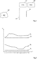
- the figure 2 is a diagram illustrating a principle of operation of the system of figure 1 . More particularly, the figure 2 represents, for four distinct pixels P 1 , P 2 , P 3 , P 4 of the sensor 101, the value of the pixel in each of the n 2D images acquired by the sensor 101 with a view to constructing a depth map and / or of a fully focused image.
- the abscissa axis represents the rank i of the images in the series of 2D images acquired by the sensor, with i integer ranging from 1 to n
- the ordinate axis represents the value V of the pixels in the corresponding images.
- the values of the pixels P 1 and P 3 are substantially constant in the series of 18 images acquired by the sensor 101.
- the pixels P 1 and P 3 typically correspond to pixels situated opposite zones uniforms of the scene, for which the modification of the focusing of the acquisition device does not result in a significant modification of the light intensity received by the pixel.
- the values of the pixels P 2 and P 4 vary significantly between the different images.
- the pixels P 2 and P 4 typically correspond to pixels located facing fronts or contours of the image, or facing areas adjacent to fronts or contours of the image, for which the modification of the focus of the device acquisition results in a significant modification of the light intensity received by the pixel.
- the image in which the output value of a pixel P j , where j is an integer representing the index or the position of the pixel in the sensor, passes through an extremum, corresponds to the image for which the point of the scene located opposite pixel P j is the sharpest.
- the rank of the image for which the value of the pixel passes through an extremum is therefore representative of the distance between the acquisition device and the corresponding point of the scene.
- a depth map of a scene in order to construct a depth map of a scene from a series of 2D images of the scene acquired by the sensor 101, provision is made to search, for each pixel position in the series of images, an extremum of the value of the pixel, and to assign to the pixel a depth value according to the rank of the image in which the extremum was detected.
- the set of depth values assigned to the pixels constitutes a depth map of the scene.
- the likelihood estimator is a function of the dynamics of the variation in the value of the pixel in the series of 2D images.
- the likelihood estimator is equal to the difference between the maximum value and the minimum value of the pixel in the series of 2D images acquired by the sensor.
- the likelihood estimators assigned to pixels P 1 and P 2 will be relatively low compared to the likelihood estimators assigned to pixels P 2 and P 4 .
- the relevance of the depth estimate obtained by the proposed method is lower in the uniform zones of the scene than in the contrasted zones.
- the likelihood estimator is a function of the dynamics of a local variation in the value of the pixel in the series of 2D images, that is to say of the dynamics of a local variation of the pixel value. pixel value on the curves of the figure 2 .
- the set of depth estimators assigned to the pixels constitutes a likelihood map of the scene.
- the value of the extremum of the pixel can also be stored so as to construct a so-called fully focused image, that is to say in which, for each pixel, the value adopted for the pixel is that of the image in which the pixel is the sharpest.
- the likelihood map can for example be used during a subsequent processing to determine, for each pixel, whether the depth value and / or the focused value determined for the pixel are sufficiently reliable.
- the likelihood map can be used to detect contours in the image, the likelihood estimators being a priori higher at the level of the contours than in the uniform zones of the image.
- various filtering operations For example, provision can be made for a method for post-processing the likelihood map comprising a first high-pass filtering step, followed by local smoothing and then by extraction of the pixels corresponding to the local maxima of the likelihood map. To reduce the impact of noise, this processing can for example be carried out on a previously sub-sampled image resulting from the selection - by block - of the pixels with the highest likelihood value.
- These three steps can advantageously be implemented iteratively a plurality of times. For example, the three aforementioned steps can be repeated in a loop until a previously defined stop criterion is reached.
- the figure 3 is a block diagram illustrating an example of a method of constructing a depth map of a scene and / or a fully focused image of the scene, based on the principles discussed in relation to figures 1 and 2 .
- the figure 3 represents more particularly a method of acquiring a depth value and / or a focused value for a given pixel P j of the sensor 101 of the figure 1 .
- This same method can however be implemented in parallel, for example simultaneously, for all the pixels of the sensor.
- the senor supplies an output value of the pixel P j , representative of the level of illumination received by the pixel during an integration phase.
- the focusing of the acquisition device is set to a first state.
- step 302 (“Is the value an extremum?") Subsequent to step 301, the processing circuit 109 ( figure 1 ) determines whether the value acquired in step 301 is an extremum among the series of values already acquired for this pixel.
- step 302 the processing circuit 109 determines that the value of the pixel is an extremum, then the value of the pixel and the rank of the corresponding acquisition are saved in a step 304 ("Save value and index focus "). Alternatively, if it is desired to construct only a fully focused image and not a depth map, the rank of the acquisition may not be saved in step 304.
- step 306 (“Modification of the focus”) subsequent to step 304, the adjustment of the focus of the device is modified, for example by means of the control circuit 107 ( figure 1 ), then steps 301 to 306 are repeated.
- step 302 the processing circuit 109 determines that the value of the pixel is not an extremum, then step 304 is omitted and step 306 is carried out directly.
- the last extremum value saved for the pixel, and, where appropriate, the corresponding acquisition rank can be used to respectively construct a fully focused image and a map. depth of the scene.
- the extremum search implemented in step 302 can be performed by comparing two by two the consecutive values of the series of output values of the pixel.
- the extremum search can be performed by searching for a change in sign of the derivative of the series of output values of the pixel. More generally, any known method of searching for extremum in a series of values can be used.
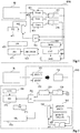
- the figure 4 schematically and partially illustrates an example of a sensor suitable for acquiring a depth map of a scene and / or a fully focused image of a scene according to one embodiment.
- each of the pixels P j of the sensor comprises its own processing circuit 400j.
- the processing circuit 400j can be integrated into the pixel P j , within the matrix of pixels, or be offset at the periphery of the matrix of pixels, for example at the bottom or at the top of the column.
- the processing circuit 400j can be deported outside the sensor.
- the processing circuit 400j can be an analog processing circuit, in particular if it is integrated into the pixel, or a digital processing circuit, in which case it can be placed downstream of a stage for digitizing the output values of the pixels. .
- Pixel P j has not been detailed, the embodiments described being compatible with all or most of the known pixel structures.
- the circuit 400j comprises three registers 451 (Vmax), 452 (Vcur) and 453 (Vmin) connected to the output of the pixel P j .
- Circuit 400 j further comprises two comparators 455 and 456.
- Circuit 400 j further comprises an iteration counter 458 (CPT) and two registers 459 (imax) and 460 (imin) connected to the output of counter 458.
- this value or current output value of the pixel is written in the register 452 (Vcur), and the iteration counter 458 (CPT) is incremented.
- the current output value of the pixel is compared, via comparator 455, with the value contained in register 451 (Vmax), and, via comparator 456, with the value contained in register 453 (Vmin).
- the value stored in register 451 (Vmax) is replaced by the current output value of the pixel, and the value stored in register 459 (imax) is replaced by the current value of iteration counter 458. Otherwise, the values stored in the registers 451 (Vmax) and 459 (imax) remain unchanged.
- the value stored in register 453 (Vmin) is replaced by the current output value of the pixel, and the value stored in register 460 (imin) is replaced by the current value of iteration counter 458. Otherwise, the values stored in the registers 453 (Vmin) and 460 (imin) remain unchanged.
- the circuit 400j comprises an OR gate 461 and a multiplexer 462 of two inputs to one output.
- the OR gate receives on a first input the signal of output of comparator 455 and on a second input the output signal of comparator 456.
- the output signal of OR gate 461 controls multiplexer 462.
- a first input of multiplexer 462 is connected to the output of pixel P j , the second input of multiplexer 462 being connected to the output of register 471.
- the output of multiplexer 462 is connected to the input of register 471.
- registers 451 (Vmax) and 453 (Vmin) are for example initialized respectively to the minimum value which can be entered in the register and to the maximum value that can be entered in the register. Additionally, iteration counter 458 can be reset.
- the register 451 contains the maximum value acquired for the pixel P j
- the register 453 contains the minimum value acquired for pixel P j
- register 459 (imax) contains the rank of the acquisition which produced the maximum value of pixel P j
- register 460 (imin) contains the rank of acquisition which produced the minimum value of pixel P j
- the output register 471 contains the value of the last detected extremum for the pixel, which can be either the maximum or the minimum. This value constitutes the final output value of the pixel which can be used for example for the construction of a fully focused image.
- the circuit 400j further comprises a decision logic circuit 463 (DECISION) adapted, from the rank values stored in the registers 459 and 460, to determine whether the extremum stored in the output register 471 is the maximum or the minimum. output values supplied by pixel P j .
- circuit 463 can compare the row values stored in registers 459 (imax) and 460 (imin). The larger of the two rank values corresponds to the last of the extremes detected, and therefore to the rank of the pixel value stored in the output register 471.
- This rank value is then written by the decision circuit 463 in a second control register. exit 473 (RG). This value constitutes the pixel depth value, which can be used for example for the construction of a depth map of the scene.
- Circuit 400j further comprises a third output register 475 (VR) in which is written a value equal to the difference between the value stored in register 451 (Vmax) and the value stored in register 453 (Vmin) at the end. of the acquisition phase.
- This value constitutes a likelihood estimator of the depth value assigned to the pixel.
- the figure 5 schematically and partially illustrates another example of a sensor suitable for acquiring a depth map of a scene and / or a fully focused image of a scene according to one embodiment.
- the sensor of the figure 5 differs from the sensor of the figure 4 in that in the sensor of the figure 5 , the 400j processing circuit of the figure 4 is replaced by a 500j processing circuit.
- the circuit 500 j comprises two registers 551 (pix (n-1)) and 552 (pix (n)).
- the circuit 500 j further includes a branch circuit 554, and an iteration counter 556 (CPT).
- the iteration counter 556 On each acquisition of an illumination value by the pixel P j , the iteration counter 556 is incremented, the current output value of the pixel is written into the register 552 (pix (n)), and the value previously stored in register 552 (pix (n)) is written in register 551 (pix (n-1)).
- the two values are transmitted to the branch circuit 554 which calculates the difference between the current output value of the pixel (stored in register 552) and the previous output value of the pixel (stored in register 551). This difference corresponds to the derivative of the output value of the pixel.
- the circuit 500j further comprises a circuit for detecting an inversion of the sign of this difference.
- the inversion detection circuit comprises a comparator 558 comparing to zero the result of the difference calculated by the branch circuit 554.
- the result of the comparison is stored in a buffer or delay circuit. 559.
- the inversion detection circuit further comprises a NAND logic gate 561 receiving on a first input the signal stored in the buffer 559, corresponding to the output signal of the comparator 558 in the preceding iteration, and, on a second input. input, the current output signal of comparator 558.
- the output signal of logic gate 561 goes high when the sign of the difference calculated by bypass circuit 554 changes between two successive acquisitions of an output value of pixel P j .
- the register 571 contains the value of the pixel corresponding to the last extremum detected in the series of output values of the pixel acquired. This value constitutes the final output value of the pixel which can be used for example for the construction of a fully focused image.
- register 573 contains the rank of this extremum in the series of output values of the pixel. This value constitutes the pixel depth value, which can be used for example for the construction of a depth map of the scene.
- the first and last values acquired for the pixel are also stored in registers not shown.
- the difference between the pixel value stored in the output register 571 and the first output value of the pixel is calculated and written in a register 563 (pix (n-1) -pix ( 1)).
- the difference between the pixel value stored in the output register 571 and the last output value of the pixel is calculated and written to register 565 (pix (n-1) -pix (end)).
- the circuit 500j further comprises a multiplexer 568 of two inputs (connected respectively to the output of register 563 and to the output of register 565) to an output (connected to the input of register 575), the control of which is linked to the output of comparator 567.
- the value stored in output register 575 (VR) at the end of the acquisition phase constitutes a likelihood estimator of the depth value assigned to the pixel.
- One advantage of the embodiments described lies in the low computational complexity of the proposed method of constructing a depth map and / or a fully focused image.
- the proposed method only takes into account the variations in the value of the pixel in the series of 2D images acquired by the sensor, but does not take into account the output values of other sensor pixels. This significantly simplifies the implementation of the method compared to known methods.
- any other suitable device can be used to implement the proposed method of constructing a depth map of a scene and / or a fully focused image of a scene, based on research, for each pixel position, of an extremum in the series of values acquired for the pixel.
- the described embodiments are not limited to the aforementioned examples of methods of searching for extremum in the series of values acquired for each pixel. More generally, any known extremum search method can be used.
- a pre-processing for example a smoothing processing, for example of the high-pass filtering type, can be implemented on the series of values acquired for the pixel, prior to the search for extremum. , in order to reduce the sensitivity of the method to extraneous noise.
- the embodiments described are not limited to the examples of method for calculating the likelihood estimator of each pixel described in relation to the figures 4 and 5 . More generally, other likelihood estimators can be used, for example the maximum of the absolute value of the derivative of order n of the value of the pixel in the series of images, or the standard deviation of the absolute value. the derivative of order n of the value of the pixel in the series of images.
Landscapes
- Engineering & Computer Science (AREA)
- Physics & Mathematics (AREA)
- General Physics & Mathematics (AREA)
- Theoretical Computer Science (AREA)
- Multimedia (AREA)
- Signal Processing (AREA)
- Computer Vision & Pattern Recognition (AREA)
- Life Sciences & Earth Sciences (AREA)
- Health & Medical Sciences (AREA)
- Biomedical Technology (AREA)
- General Health & Medical Sciences (AREA)
- Molecular Biology (AREA)
- Measurement Of Optical Distance (AREA)
- Image Processing (AREA)
- Focusing (AREA)
- Studio Devices (AREA)
Claims (10)
- Verfahren zum Erzeugen, mittels einer Signalverarbeitungsvorrichtung (109; 400j; 500j), einer Tiefenkarte und/oder eines voll fokussierten Bildes einer Szene (105) aus einer Reihe von Bildern der Szene, die jeweils eine gleiche Anzahl von Pixeln (Pj) aufweisen, wobei die Bilder unter einem gleichen Betrachtungswinkel, aber mit einer unterschiedlichen Fokussierung aufgenommen werden, wobei das Verfahren für jede Position eines Pixels (Pj) in der Reihe von Bildern die folgenden Schritte aufweist:a) Suche nach einem Extremum des Pixelwertes oder nach einer Ableitung des Pixelwertes in der Reihe von Bildern, indem nur die Werte des Pixels an der betrachteten Position in der Reihe von Bildern berücksichtigt werden;b) Zuweisen zu dieser Position eines Pixels (Pj):- eines ersten Werts, der eine Funktion des Rangs des Bildes in der Reihe von Bildern ist, bei dem das letzte Extremum in Schritt a) identifiziert worden ist, um eine Tiefenkarte der Szene zu konstruieren, und/oder- eines zweiten Werts, der dem Wert des Pixels in dem Bild entspricht, bei dem in Schritt a) das letzte Extremum identifiziert wurde, um ein voll fokussiertes Bild der Szene zu konstruieren;c) Zuweisen zu dieser Position eines Pixels (Pj) eines dritten Wertes der repräsentativ für die Relevanz des ersten und/oder zweiten Wertes ist, der dem Pixel in Schritt b) zugewiesen wurde, wobei der dritte Wert bestimmt wird, indem nur die Werte des betrachteten Pixels in der Reihe von Bildern berücksichtigt werden; undd) Liefern eines Ausgabewertes, der den ersten und/oder zweiten Wert, sowie den dritten dem Pixel zugewiesenen Wert aufweist,wobei der dritte Wert repräsentativ für den dynamischen Bereich der Variation des Wertes des Pixels (Pj) in der Reihe von Bildern ist.
- Verfahren nach Anspruch 1, wobei der dritte Wert gleich der Differenz zwischen dem Maximalwert und dem Minimalwert des Pixels (Pj) in der Reihe von Bildern ist.
- Verfahren nach Anspruch 1, wobei der dritte Wert repräsentativ für den dynamischen Bereich einer lokalen Variation des Wertes des Pixels (Pj) in der Reihe von Bildern ist.
- Verfahren nach einem der Ansprüche 1 bis 3, wobei in Schritt a) die Suche nach einem Extremum durchgeführt wird, indem die Werte des Pixels (Pj) in den aufeinanderfolgenden Bildern der Reihe von Bildern paarweise verglichen werden.
- Verfahren nach einem der Ansprüche 1 bis 3, wobei in Schritt a) die Suche nach einem Extremum durch Suche nach einem Vorzeichenwechsel der Ableitung des Wertes des Pixels (Pj) in den aufeinanderfolgenden Bildern der Reihe von Bildern durchgeführt wird.
- Eine Signalverarbeitungsvorrichtung (109), die in der Lage ist, das Verfahren zum Erzeugen einer Tiefenkarte und/oder eines voll fokussierten Bildes einer Szene (105) nach einem der Ansprüche 1 bis 5 zu implementieren.
- Ein System, das Folgendes aufweist:eine Erfassungsvorrichtung mit einem Bildsensor (101), einem optischen System (103), das gegenüber dem Sensor (101) angeordnet ist, und einer Steuerschaltung (107), die in der Lage ist, die Erfassung einer Reihe von Bildern durch den Sensor (101) zu steuern, indem bei jeder Erfassung eine Fokuseinstellung der Erfassungsvorrichtung modifiziert wird; unddie Signalverarbeitungsvorrichtung (109) nach Anspruch 6, die konfiguriert ist zum Erzeugen einer Tiefenkarte und/oder eines voll fokussierten Bildes einer Szene (105), die von dem Sensor (101) gesehen wird, und zwar aus der Reihe der von der Erfassungsvorrichtung erfassten Bilder.
- System nach Anspruch 7, wobei die Verarbeitungsvorrichtung (109) für jedes Pixel (Pj) eine Verarbeitungsschaltung (400j; 500j) aufweist, die in der Lage ist, ein Extremum des Ausgabewertes des Pixels (Pj) aus einer Reihe von aufeinanderfolgenden Ausgabewerten, die von dem Pixel geliefert werden, zu identifizieren.
- System nach Anspruch 8, wobei jede Verarbeitungsschaltung (400j; 500j) in der Lage ist, die Ausgabewerte des ihr zugeordneten Pixels (Pj) fliegend zu verarbeiten.
- System nach Anspruch 8 oder 9, wobei jede Verarbeitungsschaltung (400j; 500j) in das ihr zugeordnete Pixel (Pj) integriert ist.
Applications Claiming Priority (1)
| Application Number | Priority Date | Filing Date | Title |
|---|---|---|---|
| FR1659497A FR3057095B1 (fr) | 2016-10-03 | 2016-10-03 | Procede de construction d'une carte de profondeur d'une scene et/ou d'une image entierement focalisee |
Publications (2)
| Publication Number | Publication Date |
|---|---|
| EP3301644A1 EP3301644A1 (de) | 2018-04-04 |
| EP3301644B1 true EP3301644B1 (de) | 2020-10-21 |
Family
ID=57396716
Family Applications (1)
| Application Number | Title | Priority Date | Filing Date |
|---|---|---|---|
| EP17193337.7A Active EP3301644B1 (de) | 2016-10-03 | 2017-09-26 | Verfahren zur erstellung einer tiefenkarte einer szene und/oder eines vollkommen fokussierten bildes |
Country Status (3)
| Country | Link |
|---|---|
| US (1) | US10477187B2 (de) |
| EP (1) | EP3301644B1 (de) |
| FR (1) | FR3057095B1 (de) |
Families Citing this family (3)
| Publication number | Priority date | Publication date | Assignee | Title |
|---|---|---|---|---|
| US11893755B2 (en) | 2018-01-19 | 2024-02-06 | Interdigital Vc Holdings, Inc. | Multi-focal planes with varying positions |
| EP4266113A3 (de) | 2018-03-23 | 2023-12-27 | InterDigital VC Holdings, Inc. | Auf multifokaler ebene basierendes verfahren zur erzeugung stereoskopischer ansichtspunkte in einem dibr-system (mfp-dibr) |
| CN112585963B (zh) | 2018-07-05 | 2024-04-09 | Pcms控股公司 | 用于2d显示器上的内容的3d感知的近眼焦平面覆盖层的方法和系统 |
Citations (1)
| Publication number | Priority date | Publication date | Assignee | Title |
|---|---|---|---|---|
| WO2016151240A1 (fr) * | 2015-03-23 | 2016-09-29 | Université de Bourgogne | Imagerie d'un objet végétal macroscopique |
Family Cites Families (6)
| Publication number | Priority date | Publication date | Assignee | Title |
|---|---|---|---|---|
| US8494301B2 (en) * | 2010-09-16 | 2013-07-23 | Eastman Kodak Company | Refocusing images using scene captured images |
| US8989447B2 (en) * | 2012-08-13 | 2015-03-24 | Texas Instruments Incorporated | Dynamic focus for computational imaging |
| US9787899B1 (en) * | 2014-08-12 | 2017-10-10 | Amazon Technologies, Inc. | Multiple captures with a variable aperture |
| US9749532B1 (en) * | 2014-08-12 | 2017-08-29 | Amazon Technologies, Inc. | Pixel readout of a charge coupled device having a variable aperture |
| US9292926B1 (en) * | 2014-11-24 | 2016-03-22 | Adobe Systems Incorporated | Depth map generation |
| US10078888B2 (en) * | 2016-01-15 | 2018-09-18 | Fluke Corporation | Through-focus image combination |
-
2016
- 2016-10-03 FR FR1659497A patent/FR3057095B1/fr not_active Expired - Fee Related
-
2017
- 2017-09-26 EP EP17193337.7A patent/EP3301644B1/de active Active
- 2017-10-01 US US15/721,937 patent/US10477187B2/en not_active Expired - Fee Related
Patent Citations (1)
| Publication number | Priority date | Publication date | Assignee | Title |
|---|---|---|---|---|
| WO2016151240A1 (fr) * | 2015-03-23 | 2016-09-29 | Université de Bourgogne | Imagerie d'un objet végétal macroscopique |
Non-Patent Citations (1)
| Title |
|---|
| SAID PERTUZ ET AL: "Analysis of focus measure operators for shape-from-focus", PATTERN RECOGNITION, vol. 46, no. 5, 1 May 2013 (2013-05-01), pages 1415 - 1432, XP055173399, ISSN: 0031-3203, DOI: 10.1016/j.patcog.2012.11.011 * |
Also Published As
| Publication number | Publication date |
|---|---|
| US20180098051A1 (en) | 2018-04-05 |
| FR3057095A1 (fr) | 2018-04-06 |
| FR3057095B1 (fr) | 2019-08-16 |
| EP3301644A1 (de) | 2018-04-04 |
| US10477187B2 (en) | 2019-11-12 |
Similar Documents
| Publication | Publication Date | Title |
|---|---|---|
| EP2465255B1 (de) | Bildaufnahmesystem und verfahren mit zwei betriebsarten | |
| EP3657784B1 (de) | Verfahren zum abschätzen eines fehlers eines bilderfassungssystems, und entsprechende systeme | |
| FR2882160A1 (fr) | Procede de capture d'images comprenant une mesure de mouvements locaux | |
| EP3301644B1 (de) | Verfahren zur erstellung einer tiefenkarte einer szene und/oder eines vollkommen fokussierten bildes | |
| JP2017208641A (ja) | 圧縮センシングを用いた撮像装置、撮像方法および撮像プログラム | |
| EP3290891B1 (de) | Verfahren und vorrichtung zur charakterisierung der abbildungsfehler eines optischen systems | |
| KR101371925B1 (ko) | 영상 초점 복원 방법 | |
| EP2746830B1 (de) | Optische Feineinstellung eines Bilderfassungsgeräts | |
| FR3028989A1 (fr) | Procede de calibration des parametres extrinseques d'une camera d'un vehicule automobile et systeme d'assistance a la conduite associe | |
| WO2020094441A1 (fr) | Capteur d'image pour la reconnaissance optique de code(s) | |
| WO2014108652A1 (fr) | Estimation de mouvement d'une image | |
| WO2017187059A1 (fr) | Methode de reglage d'un appareil de prise de vue stereoscopique | |
| FR3143807A1 (fr) | Procédé et dispositif de reconstruction d’une image de profondeur | |
| WO2024194544A1 (fr) | Procede de traitement d'une image brute, produit programme d'ordinateur et dispositif de traitement associes | |
| EP0567377B1 (de) | Verfolgungsverfahren aus verformbaren Bildelementen und/oder Bildelementen mit stark venauschten Kanten | |
| FR3054678B1 (fr) | Kit pour dispositif imageur | |
| FR3030971A1 (fr) | Procede d'estimation de flou independant du contenu de la scene et utilisation dans un systeme de mise au point automatique | |
| JP2017034595A (ja) | 画像処理装置、撮像装置および画像処理プログラム | |
| WO2024194541A1 (fr) | Procede de correction d'images, au sein d'un appareil utilisateur | |
| WO2024194540A1 (fr) | Procede de correction d'images | |
| FR3108429A1 (fr) | Système d'acquisition d'une carte de profondeur d'une scène | |
| FR3134179A1 (fr) | Procédé et système de caractérisation d’un objectif optique pour la correction d’aberrations optiques introduites par ledit objectif optique dans une image. | |
| CA3137232A1 (fr) | Procede et dispositif pour retirer la remanence dans une image infrarouge d'une scene changeante | |
| FR3103940A1 (fr) | Procédé et dispositif de traitement d’images | |
| WO2019115324A1 (fr) | Procede de synthese d'images |
Legal Events
| Date | Code | Title | Description |
|---|---|---|---|
| PUAI | Public reference made under article 153(3) epc to a published international application that has entered the european phase |
Free format text: ORIGINAL CODE: 0009012 |
|
| STAA | Information on the status of an ep patent application or granted ep patent |
Free format text: STATUS: REQUEST FOR EXAMINATION WAS MADE |
|
| 17P | Request for examination filed |
Effective date: 20170926 |
|
| AK | Designated contracting states |
Kind code of ref document: A1 Designated state(s): AL AT BE BG CH CY CZ DE DK EE ES FI FR GB GR HR HU IE IS IT LI LT LU LV MC MK MT NL NO PL PT RO RS SE SI SK SM TR |
|
| AX | Request for extension of the european patent |
Extension state: BA ME |
|
| STAA | Information on the status of an ep patent application or granted ep patent |
Free format text: STATUS: EXAMINATION IS IN PROGRESS |
|
| 17Q | First examination report despatched |
Effective date: 20200103 |
|
| GRAP | Despatch of communication of intention to grant a patent |
Free format text: ORIGINAL CODE: EPIDOSNIGR1 |
|
| STAA | Information on the status of an ep patent application or granted ep patent |
Free format text: STATUS: GRANT OF PATENT IS INTENDED |
|
| RIC1 | Information provided on ipc code assigned before grant |
Ipc: H04N 5/235 20060101ALN20200505BHEP Ipc: G06T 5/00 20060101ALI20200505BHEP Ipc: G06T 5/50 20060101ALI20200505BHEP Ipc: G06T 7/571 20170101AFI20200505BHEP |
|
| INTG | Intention to grant announced |
Effective date: 20200527 |
|
| GRAS | Grant fee paid |
Free format text: ORIGINAL CODE: EPIDOSNIGR3 |
|
| GRAA | (expected) grant |
Free format text: ORIGINAL CODE: 0009210 |
|
| STAA | Information on the status of an ep patent application or granted ep patent |
Free format text: STATUS: THE PATENT HAS BEEN GRANTED |
|
| AK | Designated contracting states |
Kind code of ref document: B1 Designated state(s): AL AT BE BG CH CY CZ DE DK EE ES FI FR GB GR HR HU IE IS IT LI LT LU LV MC MK MT NL NO PL PT RO RS SE SI SK SM TR |
|
| REG | Reference to a national code |
Ref country code: GB Ref legal event code: FG4D Free format text: NOT ENGLISH |
|
| REG | Reference to a national code |
Ref country code: CH Ref legal event code: EP |
|
| REG | Reference to a national code |
Ref country code: IE Ref legal event code: FG4D Free format text: LANGUAGE OF EP DOCUMENT: FRENCH |
|
| REG | Reference to a national code |
Ref country code: DE Ref legal event code: R096 Ref document number: 602017025762 Country of ref document: DE |
|
| REG | Reference to a national code |
Ref country code: AT Ref legal event code: REF Ref document number: 1326612 Country of ref document: AT Kind code of ref document: T Effective date: 20201115 |
|
| REG | Reference to a national code |
Ref country code: AT Ref legal event code: MK05 Ref document number: 1326612 Country of ref document: AT Kind code of ref document: T Effective date: 20201021 |
|
| REG | Reference to a national code |
Ref country code: NL Ref legal event code: MP Effective date: 20201021 |
|
| PG25 | Lapsed in a contracting state [announced via postgrant information from national office to epo] |
Ref country code: FI Free format text: LAPSE BECAUSE OF FAILURE TO SUBMIT A TRANSLATION OF THE DESCRIPTION OR TO PAY THE FEE WITHIN THE PRESCRIBED TIME-LIMIT Effective date: 20201021 Ref country code: GR Free format text: LAPSE BECAUSE OF FAILURE TO SUBMIT A TRANSLATION OF THE DESCRIPTION OR TO PAY THE FEE WITHIN THE PRESCRIBED TIME-LIMIT Effective date: 20210122 Ref country code: NO Free format text: LAPSE BECAUSE OF FAILURE TO SUBMIT A TRANSLATION OF THE DESCRIPTION OR TO PAY THE FEE WITHIN THE PRESCRIBED TIME-LIMIT Effective date: 20210121 Ref country code: RS Free format text: LAPSE BECAUSE OF FAILURE TO SUBMIT A TRANSLATION OF THE DESCRIPTION OR TO PAY THE FEE WITHIN THE PRESCRIBED TIME-LIMIT Effective date: 20201021 Ref country code: PT Free format text: LAPSE BECAUSE OF FAILURE TO SUBMIT A TRANSLATION OF THE DESCRIPTION OR TO PAY THE FEE WITHIN THE PRESCRIBED TIME-LIMIT Effective date: 20210222 |
|
| REG | Reference to a national code |
Ref country code: LT Ref legal event code: MG4D |
|
| PG25 | Lapsed in a contracting state [announced via postgrant information from national office to epo] |
Ref country code: ES Free format text: LAPSE BECAUSE OF FAILURE TO SUBMIT A TRANSLATION OF THE DESCRIPTION OR TO PAY THE FEE WITHIN THE PRESCRIBED TIME-LIMIT Effective date: 20201021 Ref country code: AT Free format text: LAPSE BECAUSE OF FAILURE TO SUBMIT A TRANSLATION OF THE DESCRIPTION OR TO PAY THE FEE WITHIN THE PRESCRIBED TIME-LIMIT Effective date: 20201021 Ref country code: LV Free format text: LAPSE BECAUSE OF FAILURE TO SUBMIT A TRANSLATION OF THE DESCRIPTION OR TO PAY THE FEE WITHIN THE PRESCRIBED TIME-LIMIT Effective date: 20201021 Ref country code: IS Free format text: LAPSE BECAUSE OF FAILURE TO SUBMIT A TRANSLATION OF THE DESCRIPTION OR TO PAY THE FEE WITHIN THE PRESCRIBED TIME-LIMIT Effective date: 20210221 Ref country code: PL Free format text: LAPSE BECAUSE OF FAILURE TO SUBMIT A TRANSLATION OF THE DESCRIPTION OR TO PAY THE FEE WITHIN THE PRESCRIBED TIME-LIMIT Effective date: 20201021 Ref country code: BG Free format text: LAPSE BECAUSE OF FAILURE TO SUBMIT A TRANSLATION OF THE DESCRIPTION OR TO PAY THE FEE WITHIN THE PRESCRIBED TIME-LIMIT Effective date: 20210121 Ref country code: SE Free format text: LAPSE BECAUSE OF FAILURE TO SUBMIT A TRANSLATION OF THE DESCRIPTION OR TO PAY THE FEE WITHIN THE PRESCRIBED TIME-LIMIT Effective date: 20201021 |
|
| PG25 | Lapsed in a contracting state [announced via postgrant information from national office to epo] |
Ref country code: HR Free format text: LAPSE BECAUSE OF FAILURE TO SUBMIT A TRANSLATION OF THE DESCRIPTION OR TO PAY THE FEE WITHIN THE PRESCRIBED TIME-LIMIT Effective date: 20201021 Ref country code: NL Free format text: LAPSE BECAUSE OF FAILURE TO SUBMIT A TRANSLATION OF THE DESCRIPTION OR TO PAY THE FEE WITHIN THE PRESCRIBED TIME-LIMIT Effective date: 20201021 |
|
| REG | Reference to a national code |
Ref country code: DE Ref legal event code: R097 Ref document number: 602017025762 Country of ref document: DE |
|
| PG25 | Lapsed in a contracting state [announced via postgrant information from national office to epo] |
Ref country code: CZ Free format text: LAPSE BECAUSE OF FAILURE TO SUBMIT A TRANSLATION OF THE DESCRIPTION OR TO PAY THE FEE WITHIN THE PRESCRIBED TIME-LIMIT Effective date: 20201021 Ref country code: EE Free format text: LAPSE BECAUSE OF FAILURE TO SUBMIT A TRANSLATION OF THE DESCRIPTION OR TO PAY THE FEE WITHIN THE PRESCRIBED TIME-LIMIT Effective date: 20201021 Ref country code: LT Free format text: LAPSE BECAUSE OF FAILURE TO SUBMIT A TRANSLATION OF THE DESCRIPTION OR TO PAY THE FEE WITHIN THE PRESCRIBED TIME-LIMIT Effective date: 20201021 Ref country code: SM Free format text: LAPSE BECAUSE OF FAILURE TO SUBMIT A TRANSLATION OF THE DESCRIPTION OR TO PAY THE FEE WITHIN THE PRESCRIBED TIME-LIMIT Effective date: 20201021 Ref country code: SK Free format text: LAPSE BECAUSE OF FAILURE TO SUBMIT A TRANSLATION OF THE DESCRIPTION OR TO PAY THE FEE WITHIN THE PRESCRIBED TIME-LIMIT Effective date: 20201021 Ref country code: RO Free format text: LAPSE BECAUSE OF FAILURE TO SUBMIT A TRANSLATION OF THE DESCRIPTION OR TO PAY THE FEE WITHIN THE PRESCRIBED TIME-LIMIT Effective date: 20201021 |
|
| PLBE | No opposition filed within time limit |
Free format text: ORIGINAL CODE: 0009261 |
|
| STAA | Information on the status of an ep patent application or granted ep patent |
Free format text: STATUS: NO OPPOSITION FILED WITHIN TIME LIMIT |
|
| PG25 | Lapsed in a contracting state [announced via postgrant information from national office to epo] |
Ref country code: DK Free format text: LAPSE BECAUSE OF FAILURE TO SUBMIT A TRANSLATION OF THE DESCRIPTION OR TO PAY THE FEE WITHIN THE PRESCRIBED TIME-LIMIT Effective date: 20201021 |
|
| 26N | No opposition filed |
Effective date: 20210722 |
|
| PG25 | Lapsed in a contracting state [announced via postgrant information from national office to epo] |
Ref country code: AL Free format text: LAPSE BECAUSE OF FAILURE TO SUBMIT A TRANSLATION OF THE DESCRIPTION OR TO PAY THE FEE WITHIN THE PRESCRIBED TIME-LIMIT Effective date: 20201021 Ref country code: IT Free format text: LAPSE BECAUSE OF FAILURE TO SUBMIT A TRANSLATION OF THE DESCRIPTION OR TO PAY THE FEE WITHIN THE PRESCRIBED TIME-LIMIT Effective date: 20201021 |
|
| PG25 | Lapsed in a contracting state [announced via postgrant information from national office to epo] |
Ref country code: SI Free format text: LAPSE BECAUSE OF FAILURE TO SUBMIT A TRANSLATION OF THE DESCRIPTION OR TO PAY THE FEE WITHIN THE PRESCRIBED TIME-LIMIT Effective date: 20201021 |
|
| REG | Reference to a national code |
Ref country code: DE Ref legal event code: R119 Ref document number: 602017025762 Country of ref document: DE |
|
| REG | Reference to a national code |
Ref country code: CH Ref legal event code: PL |
|
| REG | Reference to a national code |
Ref country code: BE Ref legal event code: MM Effective date: 20210930 |
|
| GBPC | Gb: european patent ceased through non-payment of renewal fee |
Effective date: 20210926 |
|
| PG25 | Lapsed in a contracting state [announced via postgrant information from national office to epo] |
Ref country code: IS Free format text: LAPSE BECAUSE OF FAILURE TO SUBMIT A TRANSLATION OF THE DESCRIPTION OR TO PAY THE FEE WITHIN THE PRESCRIBED TIME-LIMIT Effective date: 20210221 Ref country code: MC Free format text: LAPSE BECAUSE OF FAILURE TO SUBMIT A TRANSLATION OF THE DESCRIPTION OR TO PAY THE FEE WITHIN THE PRESCRIBED TIME-LIMIT Effective date: 20201021 |
|
| PG25 | Lapsed in a contracting state [announced via postgrant information from national office to epo] |
Ref country code: LU Free format text: LAPSE BECAUSE OF NON-PAYMENT OF DUE FEES Effective date: 20210926 Ref country code: IE Free format text: LAPSE BECAUSE OF NON-PAYMENT OF DUE FEES Effective date: 20210926 Ref country code: GB Free format text: LAPSE BECAUSE OF NON-PAYMENT OF DUE FEES Effective date: 20210926 Ref country code: FR Free format text: LAPSE BECAUSE OF NON-PAYMENT OF DUE FEES Effective date: 20210930 Ref country code: DE Free format text: LAPSE BECAUSE OF NON-PAYMENT OF DUE FEES Effective date: 20220401 Ref country code: BE Free format text: LAPSE BECAUSE OF NON-PAYMENT OF DUE FEES Effective date: 20210930 |
|
| PG25 | Lapsed in a contracting state [announced via postgrant information from national office to epo] |
Ref country code: LI Free format text: LAPSE BECAUSE OF NON-PAYMENT OF DUE FEES Effective date: 20210930 Ref country code: CH Free format text: LAPSE BECAUSE OF NON-PAYMENT OF DUE FEES Effective date: 20210930 |
|
| PG25 | Lapsed in a contracting state [announced via postgrant information from national office to epo] |
Ref country code: HU Free format text: LAPSE BECAUSE OF FAILURE TO SUBMIT A TRANSLATION OF THE DESCRIPTION OR TO PAY THE FEE WITHIN THE PRESCRIBED TIME-LIMIT; INVALID AB INITIO Effective date: 20170926 |
|
| PG25 | Lapsed in a contracting state [announced via postgrant information from national office to epo] |
Ref country code: CY Free format text: LAPSE BECAUSE OF FAILURE TO SUBMIT A TRANSLATION OF THE DESCRIPTION OR TO PAY THE FEE WITHIN THE PRESCRIBED TIME-LIMIT Effective date: 20201021 |
|
| PG25 | Lapsed in a contracting state [announced via postgrant information from national office to epo] |
Ref country code: MK Free format text: LAPSE BECAUSE OF FAILURE TO SUBMIT A TRANSLATION OF THE DESCRIPTION OR TO PAY THE FEE WITHIN THE PRESCRIBED TIME-LIMIT Effective date: 20201021 |
|
| PG25 | Lapsed in a contracting state [announced via postgrant information from national office to epo] |
Ref country code: MT Free format text: LAPSE BECAUSE OF FAILURE TO SUBMIT A TRANSLATION OF THE DESCRIPTION OR TO PAY THE FEE WITHIN THE PRESCRIBED TIME-LIMIT Effective date: 20201021 |