EP3301608B1 - Methode zur anwesenheitsdetektion von objekten für einen kabellosen leser und entsprechender leser - Google Patents
Methode zur anwesenheitsdetektion von objekten für einen kabellosen leser und entsprechender leser Download PDFInfo
- Publication number
- EP3301608B1 EP3301608B1 EP17156584.9A EP17156584A EP3301608B1 EP 3301608 B1 EP3301608 B1 EP 3301608B1 EP 17156584 A EP17156584 A EP 17156584A EP 3301608 B1 EP3301608 B1 EP 3301608B1
- Authority
- EP
- European Patent Office
- Prior art keywords
- reader
- modulation
- correlation
- subcarrier
- data
- Prior art date
- Legal status (The legal status is an assumption and is not a legal conclusion. Google has not performed a legal analysis and makes no representation as to the accuracy of the status listed.)
- Active
Links
- 238000000034 method Methods 0.000 title claims description 19
- 230000005540 biological transmission Effects 0.000 claims description 43
- 238000001514 detection method Methods 0.000 claims description 41
- 238000004891 communication Methods 0.000 claims description 40
- 238000012795 verification Methods 0.000 claims description 18
- 238000012545 processing Methods 0.000 claims description 11
- 238000005516 engineering process Methods 0.000 description 6
- 230000005672 electromagnetic field Effects 0.000 description 5
- 230000035945 sensitivity Effects 0.000 description 5
- 230000004044 response Effects 0.000 description 4
- 230000001413 cellular effect Effects 0.000 description 3
- 230000001808 coupling effect Effects 0.000 description 3
- 230000006870 function Effects 0.000 description 3
- XEEYBQQBJWHFJM-UHFFFAOYSA-N Iron Chemical compound [Fe] XEEYBQQBJWHFJM-UHFFFAOYSA-N 0.000 description 2
- 230000008859 change Effects 0.000 description 2
- 238000005259 measurement Methods 0.000 description 2
- 241001269238 Data Species 0.000 description 1
- 238000013459 approach Methods 0.000 description 1
- 230000008878 coupling Effects 0.000 description 1
- 238000010168 coupling process Methods 0.000 description 1
- 238000005859 coupling reaction Methods 0.000 description 1
- 230000001627 detrimental effect Effects 0.000 description 1
- 230000000694 effects Effects 0.000 description 1
- 238000001914 filtration Methods 0.000 description 1
- 229910052742 iron Inorganic materials 0.000 description 1
- 239000002184 metal Substances 0.000 description 1
- 229910052751 metal Inorganic materials 0.000 description 1
- 238000010561 standard procedure Methods 0.000 description 1
- 238000012546 transfer Methods 0.000 description 1
Images


Classifications
-
- H04B5/72—
-
- G—PHYSICS
- G08—SIGNALLING
- G08C—TRANSMISSION SYSTEMS FOR MEASURED VALUES, CONTROL OR SIMILAR SIGNALS
- G08C17/00—Arrangements for transmitting signals characterised by the use of a wireless electrical link
- G08C17/02—Arrangements for transmitting signals characterised by the use of a wireless electrical link using a radio link
-
- G—PHYSICS
- G01—MEASURING; TESTING
- G01S—RADIO DIRECTION-FINDING; RADIO NAVIGATION; DETERMINING DISTANCE OR VELOCITY BY USE OF RADIO WAVES; LOCATING OR PRESENCE-DETECTING BY USE OF THE REFLECTION OR RERADIATION OF RADIO WAVES; ANALOGOUS ARRANGEMENTS USING OTHER WAVES
- G01S13/00—Systems using the reflection or reradiation of radio waves, e.g. radar systems; Analogous systems using reflection or reradiation of waves whose nature or wavelength is irrelevant or unspecified
- G01S13/02—Systems using reflection of radio waves, e.g. primary radar systems; Analogous systems
- G01S13/04—Systems determining presence of a target
-
- G—PHYSICS
- G06—COMPUTING; CALCULATING OR COUNTING
- G06K—GRAPHICAL DATA READING; PRESENTATION OF DATA; RECORD CARRIERS; HANDLING RECORD CARRIERS
- G06K7/00—Methods or arrangements for sensing record carriers, e.g. for reading patterns
- G06K7/10—Methods or arrangements for sensing record carriers, e.g. for reading patterns by electromagnetic radiation, e.g. optical sensing; by corpuscular radiation
- G06K7/10009—Methods or arrangements for sensing record carriers, e.g. for reading patterns by electromagnetic radiation, e.g. optical sensing; by corpuscular radiation sensing by radiation using wavelengths larger than 0.1 mm, e.g. radio-waves or microwaves
- G06K7/10118—Methods or arrangements for sensing record carriers, e.g. for reading patterns by electromagnetic radiation, e.g. optical sensing; by corpuscular radiation sensing by radiation using wavelengths larger than 0.1 mm, e.g. radio-waves or microwaves the sensing being preceded by at least one preliminary step
- G06K7/10128—Methods or arrangements for sensing record carriers, e.g. for reading patterns by electromagnetic radiation, e.g. optical sensing; by corpuscular radiation sensing by radiation using wavelengths larger than 0.1 mm, e.g. radio-waves or microwaves the sensing being preceded by at least one preliminary step the step consisting of detection of the presence of one or more record carriers in the vicinity of the interrogation device
-
- H—ELECTRICITY
- H04—ELECTRIC COMMUNICATION TECHNIQUE
- H04B—TRANSMISSION
- H04B5/00—Near-field transmission systems, e.g. inductive loop type
Definitions
- Embodiments and embodiments of the invention relate to contactless communication between a reader and an object, in particular an NFC (“Near Field Communication”) object, for example a transponder of the label type (“tag” in English language), a contactless smart card or even a mobile phone emulated in card mode without these examples being limiting, and more particularly the detection of the possible presence of such an object by the reader.
- NFC Near Field Communication
- Near-field communication is a wireless connectivity technology which allows communication over a short distance, for example 10 cm, between electronic devices. , such as contactless smart cards or mobile phones emulated in card mode, and readers.
- NFC technology is particularly suitable for connecting any type of user device and allows quick and easy communications.
- a contactless object is an object capable of exchanging information via an antenna with another contactless object, for example a reader, according to a contactless communication protocol.
- An NFC object which is a contactless object, is an object compatible with NFC technology.
- NFC technology is an open technological platform standardized in ISO / IEC 18092 and ISO / IEC 21481 but incorporates many existing standards such as for example type A and type B protocols defined in ISO-14443 which can be communication protocols that can be used in NFC technology.
- a cellular mobile telephone can be used (if it is equipped with specific means) to exchange information with another contactless device, for example a contactless reader, using a contactless communication protocol usable in NFC technology.
- the reader During a transmission of information between a reader and an object emulated in label or card mode, the reader generates a magnetic field through its antenna which is generally in the standards conventionally used, a sine wave (the carrier) at 13.56MHz.
- the reader uses amplitude modulation of said carrier.
- the object itself demodulates the received carrier to deduce therefrom the data transmitted from the reader.
- the reader For transmission of information from the object to the reader, the reader generates the magnetic field (the carrier) without modulation.
- the antenna of the object emulating the label then modulates the field generated by the reader, according to the information to be transmitted.
- the frequency of this modulation corresponds to a subcarrier of said carrier.
- the frequency of this sub-carrier depends on the communication protocol used and may for example be equal to 848 kHz.
- This modulation is carried out by modifying the load connected to the terminals of the antenna of the object.
- the output impedance of the reader antenna changes due to the magnetic coupling between the two antennas. This results in a change in the amplitudes and / or phases of the voltages and currents present at the antennae of the reader and of the object. And, in this way, the information to be transmitted from the object to the reader is transmitted by load modulation to the antenna current of the reader.
- the load variation carried out during load modulation results in an amplitude and / or phase modulation of the signal (voltage or current) at the level of the reader antenna.
- a copy of the antenna current is generated and injected into the reader reception chain where it is demodulated and processed so as to extract the transmitted information.
- the best power transfer between the reader and the tag is obtained when the tag is equipped with a circuit matched with the resonant circuit of the reader, and itself resonant at the frequency of the signal transmitted by the reader, for example 13 , 56 MHz.
- Such a mode is for example described in the contactless communication standards and provides for transmission by the reader more or less often, for example every second, of requests and expectations for specific responses from the object.
- the calibration phase therefore provides a reference value for the amplitude of the magnetic field measured at the level of the antenna.
- the actual presence of the object is then checked using the standard procedure, that is to say sending requests and waiting for receipt of acknowledgment signals.
- the reader is equipped with a reception chain comprising a demodulator which is set to the frequency of the subcarrier used by the object to transmit information to the reader.
- this subcarrier is for example equal to 848 KHz in the type A and type B protocols defined in the ISO-14443 standard.
- the sensitivity of the detection is much lower than the sensitivity of the reception chain during receiving data from the object to the reader.
- the The detection signal will then be extremely weak due to the filtering of the carrier frequency of 13.56 MHz by the reception chain.
- the patent application EP 2602942A1 describes an NFC device capable of detecting the presence of another NFC device in its magnetic field.
- This detection is based on an observation of metrics of a detection signal at different intervals and on a statistical relationship between these metrics.
- a detection of a contactless object by a contactless reader which offers low consumption, while offering a detection sensitivity at least as good as the communication sensitivity.
- a method for detecting the possible presence of an object by a reader capable of communicating with each other by at least one contactless communication protocol.
- This method comprises a detection phase comprising transmission by an antenna of the reader of a magnetic field on a carrier signal, for example a sine wave at 13.56 MHz, having a sub-carrier, for example a sub-carrier at 848 KHz in the case of a type A or B protocol of standard 14443, modulated by a first data sequence, this modulation being chosen to be at least not interpretable by said object.
- a carrier signal for example a sine wave at 13.56 MHz
- a sub-carrier for example a sub-carrier at 848 KHz in the case of a type A or B protocol of standard 14443
- the method also comprises reception at the level of the antenna of the reader of a signal resulting from this transmission and a demodulation in the reader of the subcarrier of said resulting signal so as to extract therefrom a second sequence of data.
- the method then comprises a correlation between the two data sequences and a detection of the possible presence or the absence of said object according to the result of the correlation.
- the pulses of the electromagnetic field are generated but this field is modulated on a sub-carrier, with a modulation index chosen so as to be at least non-interpretable by said object, and the reader demodulates its own modulated subcarrier, advantageously using the reception chain and can thus correlate the signal transmitted with the signal resulting from this transmission .
- any frequency can be chosen for the modulated subcarrier in the detection phase, it is preferable to choose the frequency of the modulated subcarrier from a group formed by one or more associated reference frequencies. to one or more reference contactless communication protocols capable of being used by the object for a transmission of information to the reader.
- the modulation of the subcarrier emitted by the reader must not be able to be interpreted by the contactless object as being an effective transmission of information.
- the modulation index is expected to be greater than 7%, for example for the case of type B or F protocols of the 14443 standard.
- a modulation index of less than 7% used to modulate the subcarrier in the detection phase may possibly be detected by the contactless object but will not be interpreted as an effective transmission of information from. of the reader.
- the modulation of the subcarrier is not only non-interpretable but also non-detectable by said object.
- a modulation index will be chosen which is advantageously less than a threshold index compatible with non-detectability of the modulation by the object, for example a modulation index of less than 1%.
- the modulation index used corresponds to the minimum modulation index that the reader is able to demodulate.
- the result of a perfect correlation between the two data sequences is equal to a reference correlation value, typically the value 1.
- a reference correlation value typically the value 1.
- An absence of the object is then detected if the result of said correlation between the two data sequences is less than or equal to said reference correlation value and greater than or equal to a threshold correlation value while a possible presence of the object is detected if the result of said correlation between the two sequences data is less than the threshold correlation value.
- This threshold correlation value is advantageously determined prior to said detection phase, during a calibration phase carried out in the absence of any object.
- the determination of the threshold correlation value comprises a transmission by the antenna of the reader of the magnetic field on the carrier signal having the sub-carrier modulated by a sequence of calibration data (which may be identical to or different from said first sequence of data used in the detection phase) , reception at the antenna of the reader of a signal resulting from this transmission, a demodulation in the reader of the subcarrier of said resulting signal so as to extract therefrom a third data sequence, a correlation between the sequence of calibration data and the third sequence of data, the result of this correlation providing said threshold correlation value.
- a sequence of calibration data which may be identical to or different from said first sequence of data used in the detection phase
- the very first phase of calibration can be carried out for example in the factory, or else before the first use of the reader so as to take account of the latter's environment.
- the method advantageously further comprises, in the event of detection of a presence of the object at the end of the detection phase, a verification phase comprising a verification of the actual presence of the object.
- the presence of the modulated subcarrier in said detection phase is advantageously chosen from a group formed by one or more reference frequencies associated with one or more reference contactless communication protocols capable of being used. by the object for information transmission to the reader.
- the verification of the actual presence of the object comprises, for at least one of the reference contactless communication protocols, a transmission by the reader of specific identification request information, typically requests in accordance with the standard protocols used, and waiting for the reception of specific information in return, typically acknowledgments in accordance with said standard, transmitted by the object in accordance with this reference protocol .
- the reader In practice, if the reader is capable of detecting different types of cards, it will be able to perform this check for each of the communication protocols for which the demodulator can be adjusted to the frequency of the corresponding subcarrier until it receives an acknowledgment representative of the actual presence of an object.
- a reader capable of communicating with an object by at least one contactless communication protocol via an antenna.
- the reader comprises processing means configured to detect a possible presence or absence of the object, the processing means comprising transmission means configured to transmit, via said antenna, a magnetic field on a carrier signal, modulation means configured to modulate a subcarrier of the carrier signal by a first data sequence, said modulation being at least not interpretable by said object, reception means configured to receive at the antenna a signal resulting from this transmission, demodulation means configured to perform a demodulation of said subcarrier of said resulting signal so as to extract a second sequence of data therefrom, correlation means configured to perform a correlation between the two data sequences, and analysis means configured to detect the possible presence or absence of said object as a function of the result of the correlation.
- transmission means configured to transmit, via said antenna, a magnetic field on a carrier signal
- modulation means configured to modulate a subcarrier of the carrier signal by a first data sequence, said modulation being at least not interpretable by said object
- reception means configured to receive at the antenna a signal resulting from this transmission
- demodulation means configured
- the modulation means are configured to modulate said subcarrier with a modulation not detectable by said object.
- the modulation means are configured to modulate said subcarrier with an index of modulation below a threshold index compatible with non-detectability of said modulation by the object.
- the modulation index may for example be less than 1%.
- the modulation means are advantageously configured to modulate said subcarrier with a modulation index corresponding to the minimum modulation index capable of being demodulated by the demodulation means.
- the analysis means are configured to detect an absence of the object if the result of said correlation between the two sequences of data is less than or equal to said reference correlation value and greater than or equal to a threshold correlation value, and to detect a possible presence of the object if the result of said correlation between the two data sequences is less than the threshold correlation value.
- the reader further comprises calibration means configured to determine in the absence of any object, said threshold correlation value.
- the calibration means comprise the modulation means configured to modulate the subcarrier by a sequence of calibration data, the reception means configured to receive at the level of the antenna of the reader a resulting signal of the transmission via said antenna of said modulated subcarrier, the demodulation means configured to demodulate the subcarrier of said resulting signal so as to extract therefrom a third sequence of data, and the correlation means configured to effect a correlation between the sequence of calibration data and the third sequence of data, the result of this correlation providing said threshold correlation value.
- the reader further comprises verification means configured to, in the event of detection of a possible presence of the object, to verify the actual presence of the object.
- the reader comprises a reception chain connected to said antenna, configured to allow reception of information from said object according to said at least one contactless communication protocol and comprising the demodulation means capable of demodulating during said reception of information a sub-carrier modulated with a reference frequency chosen from a group formed by one or more reference frequencies associated with one or more reference contactless communication protocols capable of being used by the object for a transmission information to the reader, and the processing means comprise the reception chain, the frequency of the sub-carrier used by the processing means being chosen from said group.
- the verification means comprise a transmission chain and the reception chain and are configured to, for at least one of the reference contactless communication protocols, transmit specific identification request information. conforming to this reference protocol and wait for the reception of specific feedback transmitted by the object in accordance with this reference protocol.
- the calibration means are configured to determine a new threshold correlation value in the actual absence of an object.
- the reference 1 designates a reader, for example but not limited to a cellular mobile telephone emulated in reader mode or else a conventional contactless smart card or label (tag) reader such as a badge.
- a reader for example but not limited to a cellular mobile telephone emulated in reader mode or else a conventional contactless smart card or label (tag) reader such as a badge.
- Reference 2 designates a contactless object, for example a cellular mobile telephone emulated in card mode and more generally an electromagnetic transponder (tag) such as a label or a badge.
- tag electromagnetic transponder
- These two devices which in this example are NFC devices, form a contactless communication system making it possible to carry out near-field communication of the NFC type between the two devices.
- the reader 1 has an antenna 5 and the tag 2 has an antenna 21, these two antennas being intended to be coupled by close magnetic fields generated by the reader.
- the reader comprises a conventional transmission chain 10 connected between a digital processing module 3, for example a processor, and the antenna 5.
- a digital processing module for example a processor
- the transmission chain conventionally comprises means 100 configured to generate a succession of pulses at a carrier frequency, for example 13.56 MHz.
- a modulator 101 makes it possible to modulate the carrier signal as a function of the information to be transmitted to the object.
- the transmission chain also includes an amplifier 102 connected to antenna 5.
- the information transmitted from the reader to the object is demodulated by the object reception chain 2.
- the reader To carry out the transmission of information from tag 2 to reader 1, the reader generates via its antenna 5 a magnetic field not modulated in amplitude, for example in NFC communications the sine wave at 13.56 MHz.
- the antenna 21 modulates the field generated by the reader. This modulation is carried out by the object by modifying the load connected to the terminals of the antenna 21. This results in a change in the amplitudes of the voltages and currents present at the level of the antennas 21 and 5.
- This modulation is performed at a subcarrier frequency equal for example to 848 KHz in the case of protocols A and B of the ISO 14443 standard.
- a copy of the current flowing in the antenna 5 is generated so as to inject it into the reception chain 20 of the reader where the resulting signal is demodulated in a demodulator 200 so as to extract the information transmitted.
- the block 4 of the reader schematizes the conventional means allowing the generation of the copy of the current flowing in the antenna 5.
- the figure 2 schematically illustrates processing means MT configured to detect a possible presence or absence of the object 2.
- the processing means use part of the transmission and reception chains of reader 1.
- a first data sequence SQ1 comprising logic “0” and “1”, is delivered to the modulator 101 of the transmission chain so as to modulate a sub-carrier of the carrier signal generated by the generator 100.
- the figure 3 illustrates the IMP pulses of the magnetic field generated at 13.56 MHz (the carrier signal).
- the modulation of a sub-carrier, for example an 848 KHz sub-carrier, of the carrier signal, by the first data sequence SQ1 makes it possible to deliver to the antenna 5 a carrier signal having a sub-carrier modulated by the first data sequence, this transmitted signal comprising the IMPMD pulses illustrated on the figure 4 .
- the reader then receives at the level of the antenna the signal SR resulting from this transmission, that is to say resulting from its own subcarrier modulation and demodulates in the demodulator, adjusted to the frequency of the subcarrier, here 848 KHz, this signal resulting in order to extract a second sequence of data SQ2 ( figure 2 ).
- the processor 3 then comprises correlation means 30 capable of effecting a correlation between the two data sequences SQ1 and SQ2 so as to deliver a correlation result.
- the correlation is performed between the two data sequences SQ1 and SQ2 according to the formula shown on this figure 4 .
- this disagreement can also come from proximity to a metal mass, for example from the antenna 5 of the reader.
- the modulated pulses IMPMD correspond to a modulation of the subcarrier here having a frequency of 848 KHz. Consequently, this modulation frequency Fd (here equal to 848 KHz) corresponds to a period Td of the first data sequence SQ1 which is found on the modulated pulses IMPMD.
- the fact of using for the modulation of the subcarrier a frequency used by the object for the transmission of this information to the reader advantageously makes it possible to use the reception chain and in particular the demodulator of the reader, which makes it possible to 'obtaining detection of the object with a sensitivity at least as good as that obtained in the phase of communication between the reader and the object once the latter has been detected.
- the modulation index is advantageously chosen so that this modulation of the subcarrier is at least not interpretable, and preferably not detectable by the object.
- the modulation index represents the depth of the amplitude troughs and is obtained by the formula (Amax-Amin) / (Amax + Amin), Amax and Amin respectively designating the levels maximum and minimum amplitude.
- the amplitude of the unmodulated pulses is 10 volts, and a modulation of 1 millivolt is chosen, then a modulation index of around 0.01% will be obtained, which makes this modulation not detectable by the object.
- a modulation index of less than 1% is also satisfactory to make the modulation not detectable by the object.
- the modulation index used by the modulation means is advantageous for the modulation index used by the modulation means to be equal (corresponds) to the minimum modulation index that the demodulation means are capable of demodulating.
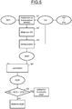
- step S1 the modulation and transmission of the modulated pulses IMPMD is carried out, as indicated above, using the first data sequence SQ1 and for the modulation frequency, a reference frequency Fdi which can be chosen from among a group of reference frequencies Fd1-Fdn likely to be used by said object in accordance with the communication protocols likely to be used by this object.
- step S2 the signal SR resulting from this transmission is detected at the level of the antenna and a copy of the current flowing in the antenna 5 of the reader is injected into the reception chain 20.
- step S3 this resulting signal SR is demodulated so as to obtain the second sequence of data item SQ2.
- step S4 the correlation between the first data sequence SQ1 and the second data sequence SQ2 is carried out so as to obtain a correlation result RCR.
- the analysis means 31 analyze this correlation result.
- a perfect correlation between the first sequence of data SQ1 and the second sequence of data SQ2 leads to an RCR correlation result equal to a reference correlation value, typically equal to 1.
- a threshold correlation value VS is defined by means, as will be seen in more detail below, of a calibration phase, and we then consider only if the correlation result RCR is less than or equal to the reference correlation value VCR and greater than or equal to the threshold correlation value VS, that there is no object.
- a phase of checking the effective presence of this object is then carried out, an example of which is illustrated on figure 6 .
- This verification phase is performed by verification means which here comprise the transmission chain and the reception chain.
- the reader transmits (step S6) for at least one of the contactless communication protocols liable to be used by the object, and for example successively for all the contactless communication protocols liable to be used. to be used by the object, information specific to identification requests, for example requests, RQ1, ... RQn conforming to this or these reference protocols.
- the reader then demodulates in step S7 the resulting signal received at the antenna level using the reference frequency modulating the subcarrier used by the object to respond according to the protocol that is implemented within the object.
- step S8 it is then verified that specific information is received in return, for example acknowledgments ACQ1, ... ACQn corresponding respectively to requests RQ1, ... RQn.
- a calibration phase whether performed before any detection phase, or in response to a possible detection of an object which has in fact turned out to be a false detection, makes it possible to determine the threshold correlation value VS or well a new threshold correlation value VS.
- This calibration phase is carried out by calibration means comprising the modulation means configured to modulate the subcarrier by a sequence of calibration data, the reception means configured to receive at the level of the antenna of the reader a signal resulting from the transmission via said antenna of said modulated subcarrier, the demodulation means configured to demodulate the subcarrier of said resulting signal so as to extract therefrom a third data sequence, and the correlation means configured to correlate between the sequence of calibration data and the third sequence of data.
- step S70 a modulation and a transmission of modulated pulses IMPMD in a manner analogous to that which has been described above, by using one or one of the frequencies of reference subcarriers Fdi as well as an SQE calibration data sequence which may be the same as or different from the first SQ1 data sequence.
- step S80 the signal resulting from this transmission (signal SR) is detected which is demodulated in step S90 within the demodulator of the reception chain so as to obtain a third data sequence SQ3.
- the correlation is carried out between the sequence of calibration data SQE and the third sequence of data SQ3 (step S100), the result of this correlation providing the initial threshold correlation value VS or a new threshold correlation value VS.
Landscapes
- Engineering & Computer Science (AREA)
- Physics & Mathematics (AREA)
- General Physics & Mathematics (AREA)
- Toxicology (AREA)
- Health & Medical Sciences (AREA)
- Remote Sensing (AREA)
- Radar, Positioning & Navigation (AREA)
- Computer Networks & Wireless Communication (AREA)
- Artificial Intelligence (AREA)
- Theoretical Computer Science (AREA)
- Computer Vision & Pattern Recognition (AREA)
- General Health & Medical Sciences (AREA)
- Electromagnetism (AREA)
- Signal Processing (AREA)
- Near-Field Transmission Systems (AREA)
Claims (24)
- Verfahren zur Detektion der eventuellen Anwesenheit eines Objekts durch einen Leser, die imstande sind, durch mindestens ein kontaktloses Kommunikationsprotokoll wechselseitig zu kommunizieren, eine Detektionsphase umfassend, die eine Übertragung, durch eine Antenne des Lesers, eines Magnetfeldes auf einem Trägersignal, das einen durch eine erste Datensequenz (SQ1) modulierten Unterträger aufweist, wobei die Modulation (101) mindestens durch das Objekt nicht interpretierbar ist, einen Empfang, im Bereich der Antenne des Lesers, eines Signals, das aus dieser Übertragung resultiert, eine Demodulation (200), in dem Leser des Unterträgers, des resultierenden Signals, um daraus eine zweite Datensequenz (SQ2) zu extrahieren, eine Korrelation (30) zwischen den beiden Datensequenzen und eine Detektion der eventuellen Anwesenheit oder der Abwesenheit des Objekts in Abhängigkeit des Ergebnisses der Korrelation, beinhaltet.
- Verfahren nach Anspruch 1, wobei die Modulation durch das Objekt nicht detektierbar ist.
- Verfahren nach Anspruch 2, wobei die Modulation einen Modulationsindex aufweist, der kleiner als ein Schwellenindex ist, der mit einer Nicht-Detektierbarkeit der Modulation durch das Objekt kompatibel ist.
- Verfahren nach Anspruch 3, wobei der Modulationsindex kleiner als 1 % ist.
- Verfahren nach Anspruch 3 oder 4, wobei der Modulationsindex einem minimalen Index entspricht, der imstande ist, demoduliert zu werden.
- Verfahren nach einem der vorstehenden Ansprüche, wobei, da das Ergebnis einer perfekten Korrelation gleich einem Referenzkorrelationswert (VCR) ist, eine Abwesenheit des Objekts detektiert wird, wenn das Ergebnis (RCR) der Korrelation zwischen den beiden Datensequenzen kleiner oder gleich dem Referenzkorrelationswert (VCR) ist, und größer oder gleich einem Schwellenkorrelationswert (VS) ist, und eine eventuelle Anwesenheit des Objekts detektiert wird, wenn das Ergebnis (RCR) der Korrelation zwischen den beiden Datensequenzen kleiner als der Schwellenkorrelationswert (VS) ist.
- Verfahren nach einem der vorstehenden Ansprüche, weiter vor der Detektionsphase eine Eichphase umfassend, die bei Abwesenheit von allen Objekten eine Bestimmung des Schwellenkorrelationswerts (VS) beinhaltet.
- Verfahren nach Anspruch 7, wobei die Bestimmung des Schwellenkorrelationswerts die Übertragung (S70), durch die Antenne des Lesers, des Magnetfelds auf dem Trägersignal, das den durch eine Eichdatensequenz (SQE) modulierten Unterträger aufweist, einen Empfang im Bereich der Antenne des Lesers eines Signals (SR), das aus dieser Übertragung resultiert, eine Demodulation (S90) in dem Leser des Unterträgers des resultierenden Signals, um daraus eine dritte Datensequenz (SQ3) zu extrahieren, eine Korrelation (S100) zwischen der Eichdatensequenz und der dritten Datensequenz umfasst, wobei das Ergebnis dieser Korrelation den dritten Schwellenkorrelationswert (VS) bereitstellt.
- Verfahren nach einem der vorstehenden Ansprüche, im Falle einer Detektion einer eventuellen Anwesenheit des Objekts am Ende der Detektionsphase weiter eine Überprüfungsphase (S6-S8) umfassend, die eine Überprüfung der effektiven Anwesenheit des Objekts beinhaltet.
- Verfahren nach einem der vorstehenden Ansprüche, wobei die Frequenz des in der Detektionsphase modulierten Unterträgers aus einer Gruppe ausgewählt wird, die durch eine oder mehrere Referenzfrequenzen (Fdi) gebildet wird, die einem oder mehreren kontaktlosen Referenz-Kommunikationsprotokollen zugeordnet sind, die von dem Objekt für eine Übertragung von Informationen zum Leser verwendet werden können.
- Verfahren nach den Ansprüchen 9 und 10, wobei in der Überprüfungsphase die Überprüfung der effektiven Anwesenheit des Objekts für mindestens eines der kontaktlosen Referenz-Kommunikationsprotokolle eine Übertragung, durch den Leser, spezifischer Identifizierungsanfrageinformationen (RQi) entsprechend diesem Referenzprotokoll, und ein Warten auf den Empfang spezifischer Informationen im Gegenzug (ACKi), die von dem Objekt entsprechend diesem Referenzprotokoll übertragen werden, umfasst.
- Verfahren nach Anspruch 7 oder 8 in Kombination mit einem der Ansprüche 9 bis 11, eine erneute Ausführung (S9) der Eichphase bei effektiver Abwesenheit des Objekts umfassend, um einen neuen Schwellenkorrelationswert zu bestimmen.
- Leser, der imstande ist, mit einem Objekt durch mindestens ein kontaktloses Kommunikationsprotokoll über eine Antenne zu kommunizieren, dadurch gekennzeichnet, dass er weiter Verarbeitungsmittel (MT) umfasst, die konfiguriert sind, um eine eventuelle Anwesenheit oder Abwesenheit des Objekts zu detektieren, wobei die Verarbeitungsmittel Übertragungsmittel (10) beinhalten, die konfiguriert sind, um über die Antenne ein Magnetfeld auf einem Trägersignal zu übertragen, Modulationsmittel (101), die konfiguriert sind, um einen Unterträger des Trägersignals durch eine erste Datensequenz zu modulieren, wobei die Modulation mindestens durch das Objekt nicht interpretierbar ist, Empfangsmittel (4), die konfiguriert sind, um im Bereich der Antenne (5) ein Signal (SR) zu empfangen, das aus dieser Übertragung resultiert, Demodulationsmittel (200), die konfiguriert sind, um eine Demodulation des Unterträgers des resultierenden Signals durchzuführen, um daraus eine zweite Datensequenz zu extrahieren, Korrelationsmittel (30), die konfiguriert sind, um eine Korrelation zwischen den beiden Datensequenzen durchzuführen, und Analysemittel (31), die konfiguriert sind, um die Detektion der eventuellen Anwesenheit oder der Abwesenheit des Objekts in Abhängigkeit von dem Ergebnis der Korrelation durchzuführen.
- Leser nach Anspruch 13, wobei die Modulationsmittel (101) konfiguriert sind, um den Unterträger mit einer Modulation zu modulieren, die durch das Objekt nicht detektierbar ist.
- Leser nach Anspruch 14, wobei die Modulationsmittel (101) konfiguriert sind, um den Unterträger mit einem Modulationsindex zu modulieren, der kleiner als ein Schwellenindex ist, der mit einer Nicht-Detektierbarkeit der Modulation durch das Objekt kompatibel ist.
- Leser nach Anspruch 15, wobei die Modulationsmittel (101) konfiguriert sind, um den Unterträger mit einem Modulationsindex kleiner als 1 % zu modulieren.
- Leser nach einem der Ansprüche 15 oder 16, wobei die Modulationsmittel (101) konfiguriert sind, um den Unterträger mit einem Modulationsindex zu modulieren, der einem minimalen Modulationsindex entspricht, der imstande ist durch die Demodulationsmittel (200) demoduliert zu werden.
- Leser nach einem der Ansprüche 13 bis 17, wobei, da das Ergebnis einer perfekten Korrelation gleich einem Referenzkorrelationswert ist, die Analysemittel (31) konfiguriert sind, um eine Abwesenheit des Objekts zu detektieren, wenn das Ergebnis der Korrelation zwischen den beiden Datensequenzen kleiner oder gleich dem Referenzkorrelationswert ist, und größer oder gleich einem Schwellenkorrelationswert ist, und um eine eventuelle Anwesenheit des Objekts zu detektieren, wenn das Ergebnis der Korrelation zwischen den beiden Datensequenzen kleiner als der Schwellenkorrelationswert ist.
- Leser nach Anspruch 18, weiter Eichmittel umfassend, die konfiguriert sind, um bei Abwesenheit aller Objekte den Schwellenkorrelationswert zu bestimmen.
- Leser nach Anspruch 19, wobei die Eichmittel die Modulationsmittel (101), die konfiguriert sind, um den Unterträger durch eine Eichdatensequenz (SQE) zu modulieren, die Empfangsmittel (4), die konfiguriert sind, um im Bereich der Antenne (5) des Lesers ein Signal zu empfangen, das aus der Übertragung des modulierten Unterträgers über die Antenne resultiert, die Demodulationsmittel (200), die konfiguriert sind, um den Unterträger des resultierenden Signals zu demodulieren, um daraus eine dritte Datensequenz zu extrahieren, und die Korrelationsmittel (30), die konfiguriert sind, um eine Korrelation zwischen der Eichdatensequenz und der dritten Datensequenz durchzuführen, umfassen, wobei das Ergebnis dieser Korrelation den dritten Schwellenkorrelationswert bereitstellt.
- Leser nach einem der Ansprüche 13 bis 20, weiter Überprüfungsmittel umfassend, die konfiguriert sind, um im Falle einer Detektion einer eventuellen Anwesenheit des Objekts die effektive Anwesenheit des Objekts zu überprüfen.
- Leser nach einem der Ansprüche 13 bis 21, umfassend eine Empfangskette (20), die mit der Antenne (5) verbunden ist, die konfiguriert ist, um einen Empfang von Informationen von dem Objekt gemäß dem mindestens einen kontaktlosen Kommunikationsprotokoll zu ermöglichen, und die Demodulationsmittel (200) beinhaltend, die imstande sind, bei Empfang von Informationen einen mit einer Referenzfrequenz modulierten Unterträger zu demodulieren, die aus einer Gruppe ausgewählt wird, die durch eine oder mehrere Referenzfrequenzen (Fdi) gebildet wird, die einem oder mehreren kontaktlosen Referenz-Kommunikationsprotokollen zugeordnet sind, die von dem Objekt für eine Übertragung von Informationen zum Leser verwendet werden können, und
wobei die Verarbeitungsmittel (MT) die Empfangskette beinhalten, wobei die Frequenz des Unterträgers, die von den Verarbeitungsmitteln verwendet wird, aus der Gruppe ausgewählt wird. - Leser nach den Ansprüchen 21 und 22, wobei die Überprüfungsmittel eine Sendekette (10) und die Empfangskette (20) umfassen, und konfiguriert sind, um für mindestens eines der kontaktlosen Kommunikationsprotokolle spezifische Identifizierungsanfrageinformationen entsprechend diesem Referenzprotokoll zu übertragen, und auf den Empfang spezifischer Informationen im Gegenzug, die von dem Objekt entsprechend diesem Referenzprotokoll übertragen werden, zu warten.
- Leser nach dem Anspruch 19 oder 20, in Verbindung mit einem der Ansprüche 21 oder 23, wobei die Eichmittel konfiguriert sind, um bei effektiver Abwesenheit eines Objekts einen neuen Schwellenkorrelationswert (VS) zu bestimmen.
Applications Claiming Priority (1)
| Application Number | Priority Date | Filing Date | Title |
|---|---|---|---|
| FR1659285A FR3056793A1 (fr) | 2016-09-29 | 2016-09-29 | Procede de detection de la presence eventuelle d'un objet par un lecteur sans contact, et lecteur correspondant |
Publications (2)
| Publication Number | Publication Date |
|---|---|
| EP3301608A1 EP3301608A1 (de) | 2018-04-04 |
| EP3301608B1 true EP3301608B1 (de) | 2020-07-29 |
Family
ID=58054201
Family Applications (1)
| Application Number | Title | Priority Date | Filing Date |
|---|---|---|---|
| EP17156584.9A Active EP3301608B1 (de) | 2016-09-29 | 2017-02-17 | Methode zur anwesenheitsdetektion von objekten für einen kabellosen leser und entsprechender leser |
Country Status (4)
| Country | Link |
|---|---|
| US (2) | US10103782B2 (de) |
| EP (1) | EP3301608B1 (de) |
| CN (2) | CN107889086B (de) |
| FR (1) | FR3056793A1 (de) |
Families Citing this family (5)
| Publication number | Priority date | Publication date | Assignee | Title |
|---|---|---|---|---|
| FR3067534A1 (fr) * | 2017-06-09 | 2018-12-14 | Stmicroelectronics (Rousset) Sas | Procede de controle du niveau de puissance emise par un dispositif de communication sans contact, par exemple un lecteur, et dispositif de communication sans contact correspondant |
| EP3584949B1 (de) * | 2018-06-19 | 2022-01-19 | STMicroelectronics razvoj polprevodnikov d.o.o. | Verfahren zur begrenzung des pegels eines modulierten signals, das durch ein etikett empfangen wird, und zugehöriger begrenzer |
| KR102640294B1 (ko) * | 2018-11-27 | 2024-02-22 | 삼성전자주식회사 | Nfc 회로 및 이의 동작 방법 |
| KR102613656B1 (ko) * | 2020-12-17 | 2023-12-15 | 한국전자통신연구원 | Gmi 마그네토미터를 이용하는 자기장 통신 방법 및 장치 |
| CN114726406A (zh) * | 2022-03-31 | 2022-07-08 | 深圳市汇顶科技股份有限公司 | 近场通信的方法、近场通信接收设备和芯片 |
Family Cites Families (20)
| Publication number | Priority date | Publication date | Assignee | Title |
|---|---|---|---|---|
| FR2792134B1 (fr) * | 1999-04-07 | 2001-06-22 | St Microelectronics Sa | Detection de distance entre un transpondeur electromagnetique et une borne |
| FR2792132B1 (fr) * | 1999-04-07 | 2001-11-02 | St Microelectronics Sa | Borne de lecture d'un transpondeur electromagnetique fonctionnant en couplage tres proche |
| FR2792135B1 (fr) * | 1999-04-07 | 2001-11-02 | St Microelectronics Sa | Fonctionnement en complage tres proche d'un systeme a transpondeur electromagnetique |
| US7352771B2 (en) * | 2002-10-08 | 2008-04-01 | Colder Products Company | Data collision detection device and method |
| US7423422B2 (en) * | 2003-03-12 | 2008-09-09 | Anritsu Industrial Solutions Co., Ltd. | Metal detector |
| AT500605B1 (de) * | 2004-08-13 | 2007-01-15 | Schiebel Elektronische Geraete | Metall-, insbesondere minensuchgerät und verfahren zur ortung von metallobjekten |
| ATE357702T1 (de) * | 2004-10-09 | 2007-04-15 | Elektrobit Ag | Verfahren zum betrieb von rfid schreib- /lesegeräten |
| US8063746B2 (en) * | 2006-03-31 | 2011-11-22 | Assa Abloy Ab | Transponder detector for an RFID system generating a progression of detection signals |
| US20080237345A1 (en) * | 2007-03-30 | 2008-10-02 | Vivotech, Inc. | Systems, methods, and computer program products for automatically adjusting the modulation index of a wireless smart device reader |
| EP2131313A1 (de) * | 2008-06-02 | 2009-12-09 | Gemplus | Verfahren zur Anwendungsauswahl in einem drahtlosen mobilen Kommunikationsgerät in einem NFC-System und entsprechendes drahtloses mobiles Kommunikationsgerät |
| DE102009009846A1 (de) * | 2009-02-20 | 2010-09-02 | Bundesdruckerei Gmbh | Verbessertes Kartenlesegerät für kontaktlos auslesbare Karten und Verfahren zum Betreiben eines solchen Kartenlesegeräts |
| DE102010013203A1 (de) * | 2010-03-29 | 2011-09-29 | Giesecke & Devrient Gmbh | System und Verfahren zur Anwesenheitserkennung eines zweiten tragbaren Datenträgers durch einen ersten tragbaren Datenträger |
| GB2484103B (en) * | 2010-09-29 | 2018-01-03 | Broadcom Europe Ltd | Near field RF communicators |
| US20120329391A1 (en) * | 2011-06-21 | 2012-12-27 | Broadcom Corporation | Detecting a presence of near field communications (nfc) devices |
| US9026048B2 (en) * | 2011-12-05 | 2015-05-05 | Broadcom Corporation | Detecting a presence of near field communications (NFC) devices |
| US8867990B2 (en) * | 2012-02-29 | 2014-10-21 | Broadcom Corporation | Detecting a presence of near field communications (NFC) devices |
| US9465064B2 (en) * | 2012-10-19 | 2016-10-11 | Witricity Corporation | Foreign object detection in wireless energy transfer systems |
| KR102124444B1 (ko) * | 2013-03-13 | 2020-06-23 | 삼성전자주식회사 | 비접촉 ic 카드 리더의 동작 방법, 비접촉 ic 카드 리더의 탐지 회로, 이를 포함하는 비접촉 ic 카드 리더 및 카드 시스템 |
| US9495569B2 (en) * | 2013-12-20 | 2016-11-15 | General Electric Company | System and method to detect an event associated with a person relative to a bed |
| WO2017070227A1 (en) * | 2015-10-19 | 2017-04-27 | Witricity Corporation | Foreign object detection in wireless energy transfer systems |
-
2016
- 2016-09-29 FR FR1659285A patent/FR3056793A1/fr active Pending
-
2017
- 2017-02-17 EP EP17156584.9A patent/EP3301608B1/de active Active
- 2017-02-28 US US15/444,576 patent/US10103782B2/en active Active
- 2017-03-15 CN CN201710154299.XA patent/CN107889086B/zh active Active
- 2017-03-15 CN CN201720255062.6U patent/CN207382589U/zh active Active
-
2018
- 2018-08-30 US US16/118,175 patent/US10298295B2/en active Active
Non-Patent Citations (1)
| Title |
|---|
| None * |
Also Published As
| Publication number | Publication date |
|---|---|
| US10103782B2 (en) | 2018-10-16 |
| FR3056793A1 (fr) | 2018-03-30 |
| EP3301608A1 (de) | 2018-04-04 |
| US10298295B2 (en) | 2019-05-21 |
| US20180375547A1 (en) | 2018-12-27 |
| CN107889086B (zh) | 2020-12-25 |
| CN107889086A (zh) | 2018-04-06 |
| US20180091192A1 (en) | 2018-03-29 |
| CN207382589U (zh) | 2018-05-18 |
Similar Documents
| Publication | Publication Date | Title |
|---|---|---|
| EP3301608B1 (de) | Methode zur anwesenheitsdetektion von objekten für einen kabellosen leser und entsprechender leser | |
| EP3276986B1 (de) | Kontaktloses kommunikationsverfahren zwischen einem objekt, beispielsweise einem im kartenmodus emulierten mobiltelefon, und einem lesegerät durch aktive lastmodulation | |
| EP3001575B1 (de) | Verfahren zur steuerung des betriebs eines objekts, das in der lage ist, ohne einen kontakt mit einem lesegerät zu kommunizieren, entsprechende vorrichtung und entsprechendes objekt | |
| EP3561730B1 (de) | Regulierungsverfahren der phase des signals, das von einem objekt abgegeben wird, das durch aktive modulierung der ladung kontaktlos mit einem lesegerät kommunizieren kann, und entsprechendes objekt | |
| WO2011157920A1 (fr) | Procede de securisation d'une communication sans fil, dispositif recepteur et systeme de communication mettant en œuvre ce procede | |
| EP3195181B1 (de) | Vorrichtung zur validierung einer transaktion während der funkkommunikation unter verwendung des menschlichen körpers | |
| WO2009133029A1 (fr) | Procede de diagnostic d'un terminal de telephonie mobile incluant des applications sans contact | |
| EP2715607B1 (de) | Sicherung einer kommunikation zwischen einem elektromagnetischen transponder und einem endgerät | |
| EP0486364B1 (de) | Elektromagnetische Wellen nutzendes Datenaustauschsystem | |
| FR2946482A1 (fr) | Procede de detection d'un message emis par un interrogateur ou un repondeur en mode s | |
| FR2812509A1 (fr) | Procede de reconnaissance securisee entre deux appareils d'un reseau radiofrequence | |
| WO2020099747A1 (fr) | Dispositif et procédé de détection d'une ouverture ou d'une tentative d'ouverture d'un récipient fermé | |
| EP2553633A1 (de) | Funkkommunikationsgegenstand mit doppelter reichweite, und umsetzungsverfahren | |
| FR2888974A1 (fr) | Procede et systeme de communication radiofrequence avec un module electronique a contacts electriques, module et dispositif associes | |
| EP2999130B1 (de) | Kontaktloses kommunikationsverfahren zwischen zwei nfc-geräten mit reduzierung des einflusses einer externen lärmemission | |
| WO2020120483A1 (fr) | Procédé de détermination de la distance entre un dispositif d'authentification et un véhicule | |
| FR3095912A1 (fr) | Procédé de compensation d’un déphasage entre le signal émis par un objet et celui reçu d’un lecteur équipé d’un détecteur d’enveloppe et objet correspondant | |
| EP1759327B1 (de) | Kontaktloses synchronphasendemodulationsverfahren und assoziierter leser | |
| FR3085551A1 (fr) | Protection d'un transpondeur passif soumis a un champ magnetique genere par exemple par un chargeur sans contact | |
| FR3103597A1 (fr) | Procédé de contrôle du positionnement relatif de deux objets et système correspondant | |
| EP4064579A1 (de) | Verfahren zur umsetzung einer nfc-transaktion | |
| FR2860668A1 (fr) | Systeme d'identification a badge a courant circulant a travers le corps a deux modes de detection | |
| EP2570973A1 (de) | Verfahren zur Herstellung einer drahtlosen Kommunikation und zugehörige Chipkarte | |
| WO2023061984A1 (fr) | Lecteur rfid et dispositif complémentaire associé | |
| FR2776148A1 (fr) | Procede, systeme et dispositif pour transferer, par liaison electromagnetique, des informations entre des lecteurs et des objets nomades |
Legal Events
| Date | Code | Title | Description |
|---|---|---|---|
| PUAI | Public reference made under article 153(3) epc to a published international application that has entered the european phase |
Free format text: ORIGINAL CODE: 0009012 |
|
| STAA | Information on the status of an ep patent application or granted ep patent |
Free format text: STATUS: REQUEST FOR EXAMINATION WAS MADE |
|
| 17P | Request for examination filed |
Effective date: 20170217 |
|
| AK | Designated contracting states |
Kind code of ref document: A1 Designated state(s): AL AT BE BG CH CY CZ DE DK EE ES FI FR GB GR HR HU IE IS IT LI LT LU LV MC MK MT NL NO PL PT RO RS SE SI SK SM TR |
|
| AX | Request for extension of the european patent |
Extension state: BA ME |
|
| GRAP | Despatch of communication of intention to grant a patent |
Free format text: ORIGINAL CODE: EPIDOSNIGR1 |
|
| STAA | Information on the status of an ep patent application or granted ep patent |
Free format text: STATUS: GRANT OF PATENT IS INTENDED |
|
| INTG | Intention to grant announced |
Effective date: 20200306 |
|
| GRAS | Grant fee paid |
Free format text: ORIGINAL CODE: EPIDOSNIGR3 |
|
| GRAA | (expected) grant |
Free format text: ORIGINAL CODE: 0009210 |
|
| STAA | Information on the status of an ep patent application or granted ep patent |
Free format text: STATUS: THE PATENT HAS BEEN GRANTED |
|
| AK | Designated contracting states |
Kind code of ref document: B1 Designated state(s): AL AT BE BG CH CY CZ DE DK EE ES FI FR GB GR HR HU IE IS IT LI LT LU LV MC MK MT NL NO PL PT RO RS SE SI SK SM TR |
|
| REG | Reference to a national code |
Ref country code: CH Ref legal event code: EP |
|
| REG | Reference to a national code |
Ref country code: AT Ref legal event code: REF Ref document number: 1296654 Country of ref document: AT Kind code of ref document: T Effective date: 20200815 |
|
| REG | Reference to a national code |
Ref country code: IE Ref legal event code: FG4D Free format text: LANGUAGE OF EP DOCUMENT: FRENCH |
|
| REG | Reference to a national code |
Ref country code: DE Ref legal event code: R096 Ref document number: 602017020390 Country of ref document: DE |
|
| REG | Reference to a national code |
Ref country code: LT Ref legal event code: MG4D |
|
| REG | Reference to a national code |
Ref country code: NL Ref legal event code: MP Effective date: 20200729 |
|
| REG | Reference to a national code |
Ref country code: AT Ref legal event code: MK05 Ref document number: 1296654 Country of ref document: AT Kind code of ref document: T Effective date: 20200729 |
|
| PG25 | Lapsed in a contracting state [announced via postgrant information from national office to epo] |
Ref country code: HR Free format text: LAPSE BECAUSE OF FAILURE TO SUBMIT A TRANSLATION OF THE DESCRIPTION OR TO PAY THE FEE WITHIN THE PRESCRIBED TIME-LIMIT Effective date: 20200729 Ref country code: PT Free format text: LAPSE BECAUSE OF FAILURE TO SUBMIT A TRANSLATION OF THE DESCRIPTION OR TO PAY THE FEE WITHIN THE PRESCRIBED TIME-LIMIT Effective date: 20201130 Ref country code: SE Free format text: LAPSE BECAUSE OF FAILURE TO SUBMIT A TRANSLATION OF THE DESCRIPTION OR TO PAY THE FEE WITHIN THE PRESCRIBED TIME-LIMIT Effective date: 20200729 Ref country code: BG Free format text: LAPSE BECAUSE OF FAILURE TO SUBMIT A TRANSLATION OF THE DESCRIPTION OR TO PAY THE FEE WITHIN THE PRESCRIBED TIME-LIMIT Effective date: 20201029 Ref country code: ES Free format text: LAPSE BECAUSE OF FAILURE TO SUBMIT A TRANSLATION OF THE DESCRIPTION OR TO PAY THE FEE WITHIN THE PRESCRIBED TIME-LIMIT Effective date: 20200729 Ref country code: NO Free format text: LAPSE BECAUSE OF FAILURE TO SUBMIT A TRANSLATION OF THE DESCRIPTION OR TO PAY THE FEE WITHIN THE PRESCRIBED TIME-LIMIT Effective date: 20201029 Ref country code: AT Free format text: LAPSE BECAUSE OF FAILURE TO SUBMIT A TRANSLATION OF THE DESCRIPTION OR TO PAY THE FEE WITHIN THE PRESCRIBED TIME-LIMIT Effective date: 20200729 Ref country code: FI Free format text: LAPSE BECAUSE OF FAILURE TO SUBMIT A TRANSLATION OF THE DESCRIPTION OR TO PAY THE FEE WITHIN THE PRESCRIBED TIME-LIMIT Effective date: 20200729 Ref country code: LT Free format text: LAPSE BECAUSE OF FAILURE TO SUBMIT A TRANSLATION OF THE DESCRIPTION OR TO PAY THE FEE WITHIN THE PRESCRIBED TIME-LIMIT Effective date: 20200729 Ref country code: GR Free format text: LAPSE BECAUSE OF FAILURE TO SUBMIT A TRANSLATION OF THE DESCRIPTION OR TO PAY THE FEE WITHIN THE PRESCRIBED TIME-LIMIT Effective date: 20201030 |
|
| PG25 | Lapsed in a contracting state [announced via postgrant information from national office to epo] |
Ref country code: IS Free format text: LAPSE BECAUSE OF FAILURE TO SUBMIT A TRANSLATION OF THE DESCRIPTION OR TO PAY THE FEE WITHIN THE PRESCRIBED TIME-LIMIT Effective date: 20201129 Ref country code: LV Free format text: LAPSE BECAUSE OF FAILURE TO SUBMIT A TRANSLATION OF THE DESCRIPTION OR TO PAY THE FEE WITHIN THE PRESCRIBED TIME-LIMIT Effective date: 20200729 Ref country code: RS Free format text: LAPSE BECAUSE OF FAILURE TO SUBMIT A TRANSLATION OF THE DESCRIPTION OR TO PAY THE FEE WITHIN THE PRESCRIBED TIME-LIMIT Effective date: 20200729 Ref country code: PL Free format text: LAPSE BECAUSE OF FAILURE TO SUBMIT A TRANSLATION OF THE DESCRIPTION OR TO PAY THE FEE WITHIN THE PRESCRIBED TIME-LIMIT Effective date: 20200729 |
|
| PG25 | Lapsed in a contracting state [announced via postgrant information from national office to epo] |
Ref country code: NL Free format text: LAPSE BECAUSE OF FAILURE TO SUBMIT A TRANSLATION OF THE DESCRIPTION OR TO PAY THE FEE WITHIN THE PRESCRIBED TIME-LIMIT Effective date: 20200729 |
|
| PG25 | Lapsed in a contracting state [announced via postgrant information from national office to epo] |
Ref country code: DK Free format text: LAPSE BECAUSE OF FAILURE TO SUBMIT A TRANSLATION OF THE DESCRIPTION OR TO PAY THE FEE WITHIN THE PRESCRIBED TIME-LIMIT Effective date: 20200729 Ref country code: CZ Free format text: LAPSE BECAUSE OF FAILURE TO SUBMIT A TRANSLATION OF THE DESCRIPTION OR TO PAY THE FEE WITHIN THE PRESCRIBED TIME-LIMIT Effective date: 20200729 Ref country code: RO Free format text: LAPSE BECAUSE OF FAILURE TO SUBMIT A TRANSLATION OF THE DESCRIPTION OR TO PAY THE FEE WITHIN THE PRESCRIBED TIME-LIMIT Effective date: 20200729 Ref country code: EE Free format text: LAPSE BECAUSE OF FAILURE TO SUBMIT A TRANSLATION OF THE DESCRIPTION OR TO PAY THE FEE WITHIN THE PRESCRIBED TIME-LIMIT Effective date: 20200729 Ref country code: IT Free format text: LAPSE BECAUSE OF FAILURE TO SUBMIT A TRANSLATION OF THE DESCRIPTION OR TO PAY THE FEE WITHIN THE PRESCRIBED TIME-LIMIT Effective date: 20200729 Ref country code: SM Free format text: LAPSE BECAUSE OF FAILURE TO SUBMIT A TRANSLATION OF THE DESCRIPTION OR TO PAY THE FEE WITHIN THE PRESCRIBED TIME-LIMIT Effective date: 20200729 |
|
| REG | Reference to a national code |
Ref country code: DE Ref legal event code: R097 Ref document number: 602017020390 Country of ref document: DE |
|
| PG25 | Lapsed in a contracting state [announced via postgrant information from national office to epo] |
Ref country code: AL Free format text: LAPSE BECAUSE OF FAILURE TO SUBMIT A TRANSLATION OF THE DESCRIPTION OR TO PAY THE FEE WITHIN THE PRESCRIBED TIME-LIMIT Effective date: 20200729 |
|
| PLBE | No opposition filed within time limit |
Free format text: ORIGINAL CODE: 0009261 |
|
| STAA | Information on the status of an ep patent application or granted ep patent |
Free format text: STATUS: NO OPPOSITION FILED WITHIN TIME LIMIT |
|
| PG25 | Lapsed in a contracting state [announced via postgrant information from national office to epo] |
Ref country code: SK Free format text: LAPSE BECAUSE OF FAILURE TO SUBMIT A TRANSLATION OF THE DESCRIPTION OR TO PAY THE FEE WITHIN THE PRESCRIBED TIME-LIMIT Effective date: 20200729 |
|
| 26N | No opposition filed |
Effective date: 20210430 |
|
| PG25 | Lapsed in a contracting state [announced via postgrant information from national office to epo] |
Ref country code: SI Free format text: LAPSE BECAUSE OF FAILURE TO SUBMIT A TRANSLATION OF THE DESCRIPTION OR TO PAY THE FEE WITHIN THE PRESCRIBED TIME-LIMIT Effective date: 20200729 |
|
| PG25 | Lapsed in a contracting state [announced via postgrant information from national office to epo] |
Ref country code: MC Free format text: LAPSE BECAUSE OF FAILURE TO SUBMIT A TRANSLATION OF THE DESCRIPTION OR TO PAY THE FEE WITHIN THE PRESCRIBED TIME-LIMIT Effective date: 20200729 |
|
| GBPC | Gb: european patent ceased through non-payment of renewal fee |
Effective date: 20210217 |
|
| REG | Reference to a national code |
Ref country code: BE Ref legal event code: MM Effective date: 20210228 |
|
| PG25 | Lapsed in a contracting state [announced via postgrant information from national office to epo] |
Ref country code: CH Free format text: LAPSE BECAUSE OF NON-PAYMENT OF DUE FEES Effective date: 20210228 Ref country code: LU Free format text: LAPSE BECAUSE OF NON-PAYMENT OF DUE FEES Effective date: 20210217 Ref country code: LI Free format text: LAPSE BECAUSE OF NON-PAYMENT OF DUE FEES Effective date: 20210228 |
|
| PG25 | Lapsed in a contracting state [announced via postgrant information from national office to epo] |
Ref country code: IE Free format text: LAPSE BECAUSE OF NON-PAYMENT OF DUE FEES Effective date: 20210217 Ref country code: GB Free format text: LAPSE BECAUSE OF NON-PAYMENT OF DUE FEES Effective date: 20210217 Ref country code: FR Free format text: LAPSE BECAUSE OF NON-PAYMENT OF DUE FEES Effective date: 20210228 |
|
| PG25 | Lapsed in a contracting state [announced via postgrant information from national office to epo] |
Ref country code: BE Free format text: LAPSE BECAUSE OF NON-PAYMENT OF DUE FEES Effective date: 20210228 |
|
| PGFP | Annual fee paid to national office [announced via postgrant information from national office to epo] |
Ref country code: DE Payment date: 20230119 Year of fee payment: 7 |
|
| PG25 | Lapsed in a contracting state [announced via postgrant information from national office to epo] |
Ref country code: CY Free format text: LAPSE BECAUSE OF FAILURE TO SUBMIT A TRANSLATION OF THE DESCRIPTION OR TO PAY THE FEE WITHIN THE PRESCRIBED TIME-LIMIT Effective date: 20200729 |
|
| PG25 | Lapsed in a contracting state [announced via postgrant information from national office to epo] |
Ref country code: HU Free format text: LAPSE BECAUSE OF FAILURE TO SUBMIT A TRANSLATION OF THE DESCRIPTION OR TO PAY THE FEE WITHIN THE PRESCRIBED TIME-LIMIT; INVALID AB INITIO Effective date: 20170217 |
|
| PG25 | Lapsed in a contracting state [announced via postgrant information from national office to epo] |
Ref country code: MK Free format text: LAPSE BECAUSE OF FAILURE TO SUBMIT A TRANSLATION OF THE DESCRIPTION OR TO PAY THE FEE WITHIN THE PRESCRIBED TIME-LIMIT Effective date: 20200729 |
|
| PGFP | Annual fee paid to national office [announced via postgrant information from national office to epo] |
Ref country code: DE Payment date: 20240123 Year of fee payment: 8 |