EP3301539A1 - Electronic device and display method - Google Patents
Electronic device and display method Download PDFInfo
- Publication number
- EP3301539A1 EP3301539A1 EP17173523.6A EP17173523A EP3301539A1 EP 3301539 A1 EP3301539 A1 EP 3301539A1 EP 17173523 A EP17173523 A EP 17173523A EP 3301539 A1 EP3301539 A1 EP 3301539A1
- Authority
- EP
- European Patent Office
- Prior art keywords
- corners
- display screen
- screen
- bezel
- electronic device
- Prior art date
- Legal status (The legal status is an assumption and is not a legal conclusion. Google has not performed a legal analysis and makes no representation as to the accuracy of the status listed.)
- Ceased
Links
Images



Classifications
-
- G—PHYSICS
- G06—COMPUTING OR CALCULATING; COUNTING
- G06F—ELECTRIC DIGITAL DATA PROCESSING
- G06F1/00—Details not covered by groups G06F3/00 - G06F13/00 and G06F21/00
- G06F1/16—Constructional details or arrangements
- G06F1/1601—Constructional details related to the housing of computer displays, e.g. of CRT monitors, of flat displays
-
- G—PHYSICS
- G02—OPTICS
- G02F—OPTICAL DEVICES OR ARRANGEMENTS FOR THE CONTROL OF LIGHT BY MODIFICATION OF THE OPTICAL PROPERTIES OF THE MEDIA OF THE ELEMENTS INVOLVED THEREIN; NON-LINEAR OPTICS; FREQUENCY-CHANGING OF LIGHT; OPTICAL LOGIC ELEMENTS; OPTICAL ANALOGUE/DIGITAL CONVERTERS
- G02F1/00—Devices or arrangements for the control of the intensity, colour, phase, polarisation or direction of light arriving from an independent light source, e.g. switching, gating or modulating; Non-linear optics
- G02F1/01—Devices or arrangements for the control of the intensity, colour, phase, polarisation or direction of light arriving from an independent light source, e.g. switching, gating or modulating; Non-linear optics for the control of the intensity, phase, polarisation or colour
- G02F1/13—Devices or arrangements for the control of the intensity, colour, phase, polarisation or direction of light arriving from an independent light source, e.g. switching, gating or modulating; Non-linear optics for the control of the intensity, phase, polarisation or colour based on liquid crystals, e.g. single liquid crystal display cells
- G02F1/133—Constructional arrangements; Operation of liquid crystal cells; Circuit arrangements
- G02F1/1333—Constructional arrangements; Manufacturing methods
- G02F1/133308—Support structures for LCD panels, e.g. frames or bezels
-
- G—PHYSICS
- G06—COMPUTING OR CALCULATING; COUNTING
- G06F—ELECTRIC DIGITAL DATA PROCESSING
- G06F1/00—Details not covered by groups G06F3/00 - G06F13/00 and G06F21/00
- G06F1/16—Constructional details or arrangements
- G06F1/1613—Constructional details or arrangements for portable computers
- G06F1/1633—Constructional details or arrangements of portable computers not specific to the type of enclosures covered by groups G06F1/1615 - G06F1/1626
- G06F1/1637—Details related to the display arrangement, including those related to the mounting of the display in the housing
-
- G—PHYSICS
- G06—COMPUTING OR CALCULATING; COUNTING
- G06F—ELECTRIC DIGITAL DATA PROCESSING
- G06F1/00—Details not covered by groups G06F3/00 - G06F13/00 and G06F21/00
- G06F1/16—Constructional details or arrangements
-
- G—PHYSICS
- G02—OPTICS
- G02F—OPTICAL DEVICES OR ARRANGEMENTS FOR THE CONTROL OF LIGHT BY MODIFICATION OF THE OPTICAL PROPERTIES OF THE MEDIA OF THE ELEMENTS INVOLVED THEREIN; NON-LINEAR OPTICS; FREQUENCY-CHANGING OF LIGHT; OPTICAL LOGIC ELEMENTS; OPTICAL ANALOGUE/DIGITAL CONVERTERS
- G02F1/00—Devices or arrangements for the control of the intensity, colour, phase, polarisation or direction of light arriving from an independent light source, e.g. switching, gating or modulating; Non-linear optics
- G02F1/01—Devices or arrangements for the control of the intensity, colour, phase, polarisation or direction of light arriving from an independent light source, e.g. switching, gating or modulating; Non-linear optics for the control of the intensity, phase, polarisation or colour
- G02F1/13—Devices or arrangements for the control of the intensity, colour, phase, polarisation or direction of light arriving from an independent light source, e.g. switching, gating or modulating; Non-linear optics for the control of the intensity, phase, polarisation or colour based on liquid crystals, e.g. single liquid crystal display cells
- G02F1/133—Constructional arrangements; Operation of liquid crystal cells; Circuit arrangements
-
- G—PHYSICS
- G02—OPTICS
- G02F—OPTICAL DEVICES OR ARRANGEMENTS FOR THE CONTROL OF LIGHT BY MODIFICATION OF THE OPTICAL PROPERTIES OF THE MEDIA OF THE ELEMENTS INVOLVED THEREIN; NON-LINEAR OPTICS; FREQUENCY-CHANGING OF LIGHT; OPTICAL LOGIC ELEMENTS; OPTICAL ANALOGUE/DIGITAL CONVERTERS
- G02F1/00—Devices or arrangements for the control of the intensity, colour, phase, polarisation or direction of light arriving from an independent light source, e.g. switching, gating or modulating; Non-linear optics
- G02F1/01—Devices or arrangements for the control of the intensity, colour, phase, polarisation or direction of light arriving from an independent light source, e.g. switching, gating or modulating; Non-linear optics for the control of the intensity, phase, polarisation or colour
- G02F1/13—Devices or arrangements for the control of the intensity, colour, phase, polarisation or direction of light arriving from an independent light source, e.g. switching, gating or modulating; Non-linear optics for the control of the intensity, phase, polarisation or colour based on liquid crystals, e.g. single liquid crystal display cells
- G02F1/133—Constructional arrangements; Operation of liquid crystal cells; Circuit arrangements
- G02F1/13306—Circuit arrangements or driving methods for the control of single liquid crystal cells
-
- G—PHYSICS
- G02—OPTICS
- G02F—OPTICAL DEVICES OR ARRANGEMENTS FOR THE CONTROL OF LIGHT BY MODIFICATION OF THE OPTICAL PROPERTIES OF THE MEDIA OF THE ELEMENTS INVOLVED THEREIN; NON-LINEAR OPTICS; FREQUENCY-CHANGING OF LIGHT; OPTICAL LOGIC ELEMENTS; OPTICAL ANALOGUE/DIGITAL CONVERTERS
- G02F1/00—Devices or arrangements for the control of the intensity, colour, phase, polarisation or direction of light arriving from an independent light source, e.g. switching, gating or modulating; Non-linear optics
- G02F1/01—Devices or arrangements for the control of the intensity, colour, phase, polarisation or direction of light arriving from an independent light source, e.g. switching, gating or modulating; Non-linear optics for the control of the intensity, phase, polarisation or colour
- G02F1/13—Devices or arrangements for the control of the intensity, colour, phase, polarisation or direction of light arriving from an independent light source, e.g. switching, gating or modulating; Non-linear optics for the control of the intensity, phase, polarisation or colour based on liquid crystals, e.g. single liquid crystal display cells
- G02F1/133—Constructional arrangements; Operation of liquid crystal cells; Circuit arrangements
- G02F1/1333—Constructional arrangements; Manufacturing methods
-
- G—PHYSICS
- G02—OPTICS
- G02F—OPTICAL DEVICES OR ARRANGEMENTS FOR THE CONTROL OF LIGHT BY MODIFICATION OF THE OPTICAL PROPERTIES OF THE MEDIA OF THE ELEMENTS INVOLVED THEREIN; NON-LINEAR OPTICS; FREQUENCY-CHANGING OF LIGHT; OPTICAL LOGIC ELEMENTS; OPTICAL ANALOGUE/DIGITAL CONVERTERS
- G02F1/00—Devices or arrangements for the control of the intensity, colour, phase, polarisation or direction of light arriving from an independent light source, e.g. switching, gating or modulating; Non-linear optics
- G02F1/01—Devices or arrangements for the control of the intensity, colour, phase, polarisation or direction of light arriving from an independent light source, e.g. switching, gating or modulating; Non-linear optics for the control of the intensity, phase, polarisation or colour
- G02F1/13—Devices or arrangements for the control of the intensity, colour, phase, polarisation or direction of light arriving from an independent light source, e.g. switching, gating or modulating; Non-linear optics for the control of the intensity, phase, polarisation or colour based on liquid crystals, e.g. single liquid crystal display cells
- G02F1/133—Constructional arrangements; Operation of liquid crystal cells; Circuit arrangements
- G02F1/1333—Constructional arrangements; Manufacturing methods
- G02F1/133308—Support structures for LCD panels, e.g. frames or bezels
- G02F1/133325—Assembling processes
-
- G—PHYSICS
- G02—OPTICS
- G02F—OPTICAL DEVICES OR ARRANGEMENTS FOR THE CONTROL OF LIGHT BY MODIFICATION OF THE OPTICAL PROPERTIES OF THE MEDIA OF THE ELEMENTS INVOLVED THEREIN; NON-LINEAR OPTICS; FREQUENCY-CHANGING OF LIGHT; OPTICAL LOGIC ELEMENTS; OPTICAL ANALOGUE/DIGITAL CONVERTERS
- G02F1/00—Devices or arrangements for the control of the intensity, colour, phase, polarisation or direction of light arriving from an independent light source, e.g. switching, gating or modulating; Non-linear optics
- G02F1/01—Devices or arrangements for the control of the intensity, colour, phase, polarisation or direction of light arriving from an independent light source, e.g. switching, gating or modulating; Non-linear optics for the control of the intensity, phase, polarisation or colour
- G02F1/13—Devices or arrangements for the control of the intensity, colour, phase, polarisation or direction of light arriving from an independent light source, e.g. switching, gating or modulating; Non-linear optics for the control of the intensity, phase, polarisation or colour based on liquid crystals, e.g. single liquid crystal display cells
- G02F1/133—Constructional arrangements; Operation of liquid crystal cells; Circuit arrangements
- G02F1/1333—Constructional arrangements; Manufacturing methods
- G02F1/133388—Constructional arrangements; Manufacturing methods with constructional differences between the display region and the peripheral region
-
- G—PHYSICS
- G06—COMPUTING OR CALCULATING; COUNTING
- G06F—ELECTRIC DIGITAL DATA PROCESSING
- G06F1/00—Details not covered by groups G06F3/00 - G06F13/00 and G06F21/00
- G06F1/16—Constructional details or arrangements
- G06F1/1613—Constructional details or arrangements for portable computers
- G06F1/1626—Constructional details or arrangements for portable computers with a single-body enclosure integrating a flat display, e.g. Personal Digital Assistants [PDAs]
-
- G—PHYSICS
- G09—EDUCATION; CRYPTOGRAPHY; DISPLAY; ADVERTISING; SEALS
- G09G—ARRANGEMENTS OR CIRCUITS FOR CONTROL OF INDICATING DEVICES USING STATIC MEANS TO PRESENT VARIABLE INFORMATION
- G09G5/00—Control arrangements or circuits for visual indicators common to cathode-ray tube indicators and other visual indicators
-
- G—PHYSICS
- G09—EDUCATION; CRYPTOGRAPHY; DISPLAY; ADVERTISING; SEALS
- G09G—ARRANGEMENTS OR CIRCUITS FOR CONTROL OF INDICATING DEVICES USING STATIC MEANS TO PRESENT VARIABLE INFORMATION
- G09G5/00—Control arrangements or circuits for visual indicators common to cathode-ray tube indicators and other visual indicators
- G09G5/10—Intensity circuits
-
- H—ELECTRICITY
- H04—ELECTRIC COMMUNICATION TECHNIQUE
- H04M—TELEPHONIC COMMUNICATION
- H04M1/00—Substation equipment, e.g. for use by subscribers
- H04M1/02—Constructional features of telephone sets
- H04M1/0202—Portable telephone sets, e.g. cordless phones, mobile phones or bar type handsets
- H04M1/026—Details of the structure or mounting of specific components
- H04M1/0266—Details of the structure or mounting of specific components for a display module assembly
-
- G—PHYSICS
- G02—OPTICS
- G02F—OPTICAL DEVICES OR ARRANGEMENTS FOR THE CONTROL OF LIGHT BY MODIFICATION OF THE OPTICAL PROPERTIES OF THE MEDIA OF THE ELEMENTS INVOLVED THEREIN; NON-LINEAR OPTICS; FREQUENCY-CHANGING OF LIGHT; OPTICAL LOGIC ELEMENTS; OPTICAL ANALOGUE/DIGITAL CONVERTERS
- G02F2201/00—Constructional arrangements not provided for in groups G02F1/00 - G02F7/00
- G02F2201/12—Constructional arrangements not provided for in groups G02F1/00 - G02F7/00 electrode
- G02F2201/123—Constructional arrangements not provided for in groups G02F1/00 - G02F7/00 electrode pixel
-
- G—PHYSICS
- G09—EDUCATION; CRYPTOGRAPHY; DISPLAY; ADVERTISING; SEALS
- G09G—ARRANGEMENTS OR CIRCUITS FOR CONTROL OF INDICATING DEVICES USING STATIC MEANS TO PRESENT VARIABLE INFORMATION
- G09G2320/00—Control of display operating conditions
- G09G2320/06—Adjustment of display parameters
- G09G2320/0686—Adjustment of display parameters with two or more screen areas displaying information with different brightness or colours
-
- G—PHYSICS
- G09—EDUCATION; CRYPTOGRAPHY; DISPLAY; ADVERTISING; SEALS
- G09G—ARRANGEMENTS OR CIRCUITS FOR CONTROL OF INDICATING DEVICES USING STATIC MEANS TO PRESENT VARIABLE INFORMATION
- G09G2380/00—Specific applications
- G09G2380/14—Electronic books and readers
Definitions
- the present invention relates to a field of electronic devices, and more particularly, to an electronic device and a display method.
- displaying the preset floating layer on a top of the page includes:
- the dividing line is located at the inner side of the edges of the rounded screen corners of the display screen.
- the four sides include a first side 2022, a second side 2023, a third side 2024 and a fourth side 2025.
- the first side 2022 is in parallel with the second side 2023.
- the third side 2024 is in parallel with the fourth side 2025.
- the first side 2022 intersects the third side 2024 and the fourth side 2025 respectively.
- the second side 2023 intersects the third side 2024 and the fourth side 2025 respectively.
- the vertexes of the four screen corners 2011 are closer to the center of the display screen 201 under a condition that the size of the display screen is constant, and the widths of the four sides of the bezel can be reduced under a condition that the specific distance between the vertexes of the bezel corners and screen corners corresponding to each other is not less than the preset distance, therefore narrowing the bezel of the electronic device.
- the aesthetics of electronic equipment is enhanced greatly.
- the central angle corresponding to each of the four screen corners 2011 is equal to the central angle corresponding to each of the four bezel corners 2021, which refers to that: the center of the circle for the arc of the corresponding screen corner 2011 is the same with the center of the circle for the arc of the corresponding bezel corner 2021, extension lines of two lines of the central angle for the corresponding screen corner 2011 are coincided with extension lines of two lines of the central angle for the corresponding bezel corner 2021 respectively.
- the central angle for the corresponding screen corner 2011 and the central angle for the corresponding bezel corner 2021 both are ⁇ MO4N.
- the display screen 201 is a liquid crystal display screen.
- the liquid crystal display screen is provided with a plurality of pixel electrodes. In cutting the liquid crystal display screen, it is not necessary to provide a pixel electrode for the portion to be cut off on the liquid crystal display screen.
- step 302 when a page is displayed, the preset floating layer is displayed on a top of the page so that the first portion shades the page.
- the electronic device controls the pixels corresponding to first portion on the display screen to be black.
- the electronic device in order to ensure that the first portion obscures the displayed page, in actual operation, can control the pixels corresponding to the first portion on the display screen to be black, that is, to control the brightness of these pixels to be 0, so as to achieve the effect of blocking the page displayed on the edges of the four screen corners.
- Fig. 4 is a block diagram illustrating an electronic device 400 according to an exemplary embodiment of the present disclosure.
- the electronic device 400 may be a mobile phone, a computer, a digital broadcasting terminal, a messaging device, a game console, a tablet device, a medical device, fitness equipment, a Personal Digital Assistant PDA, and the like
- the sensor component 414 may also include a light sensor, such as a CMOS or CCD image sensor, for use in imaging applications.
- the sensor component 414 may also include an accelerometer sensor, a gyroscope sensor, a magnetic sensor, a pressure sensor, or a temperature sensor.
Landscapes
- Physics & Mathematics (AREA)
- Engineering & Computer Science (AREA)
- General Physics & Mathematics (AREA)
- Nonlinear Science (AREA)
- Theoretical Computer Science (AREA)
- Computer Hardware Design (AREA)
- Chemical & Material Sciences (AREA)
- Crystallography & Structural Chemistry (AREA)
- Mathematical Physics (AREA)
- Optics & Photonics (AREA)
- General Engineering & Computer Science (AREA)
- Human Computer Interaction (AREA)
- Signal Processing (AREA)
- Devices For Indicating Variable Information By Combining Individual Elements (AREA)
- Liquid Crystal (AREA)
Abstract
Description
- The present invention relates to a field of electronic devices, and more particularly, to an electronic device and a display method.
- With the continuous development of electronic technology, electronic devices such as mobile phones and tablet PCs are widely used in people's daily lives. When selecting an electronic device, a user may pay more and more attention to the structure of the electronic device in addition to the functions provided by the electronic device.
- The structure of the electronic device is shown usually as
Fig. 1 . This electronic device includes adisplay screen 101 and abezel 102 that surrounds sides of thedisplay screen 101. The fourscreen corners 1011 of thedisplay screen 101 are right-angled, and the fourbezel corners 1021 of thebezel 102 are round angled. The widths of the four sides of thebezel 102 are determined by respective specified distance between vertexes of thescreen corners 1011 andbezel corners 1021 corresponding to each other. - The problem existing in the known structures is the wide border.
- In order to solve the problems in the related arts, the present invention provides an electronic device and a display method. The technical solutions may be as follows.
- According to a first aspect of embodiments of the present invention, an electronic device is provided. The electronic device at least includes: a display screen and a bezel, in which the bezel surrounds sides of the display screen;
the display screen has four screen corners, and the four screen corners are rounded;
the bezel has four sides, any one of the four sides intersects two of further three sides of the four sides respectively and is in parallel with another one of the further three sides to form four bezel corners;
the four bezel corners correspond to the four screen corners respectively, and the four bezel corners are rounded;
a distance between vertexes of the bezel corners and screen corners corresponding to each other is not less than a preset distance. - According to a particular embodiment, a curvature of each of the four screen corners is equal to a curvature of each of the four bezel corners.
- According to a particular embodiment, a central angle corresponding to each of the four screen corners is equal to a central angle corresponding to each of the four bezel corners.
- According to a particular embodiment, the display screen is a liquid crystal display screen.
- According to a particular embodiment, original right-angle corners of the display screen are cut into arc shapes respectively to form the four screen corners.
- According to a second aspect of embodiments of the present invention, a display method is provided. The method is performed by the electronic device according to the first aspect of embodiments of the present invention and includes:
- acquiring a preset floating layer including a first portion and a second portion, in which the first portion is black, the second portion is transparent, a dividing line between the first portion and the second portion is an arc-shaped smooth curve;
- when a page is displayed, displaying the preset floating layer on a top of the page so that the first portion shades the page displayed on edges of the four screen corners of the display screen.
- According to a particular embodiment, when a page is displayed, displaying the preset floating layer on a top of the page includes:
- when the page is displayed, controlling pixels corresponding to the first portion on the display screen to be black.
- According to a particular embodiment, the dividing line is located at the inner side of the edges of the rounded screen corners of the display screen.
- According to a particular embodiment, a length of the preset floating layer is equal to a length of the display screen and a width of the preset floating layer is equal to a width of the display screen.
- The technical solutions provided in embodiments of the present invention may have following advantageous effects.
- With the electronic device and method provided by the embodiments, by setting the four screen corners of the display screen and the four bezel corners of the bezel to be the rounded corners, the vertexes of the four screen corners are closer to the center of the display screen under a condition that the size of the display screen is constant, and the widths of the four sides of the bezel can be reduced under a condition that the specific distance between the vertexes of the bezel corners and screen corners corresponding to each other is not less than the preset distance, therefore narrowing the bezel of the electronic device.
- It is to be understood that both the foregoing general description and the following detailed description are exemplary and explanatory only and are not restrictive of the present invention.
- Accompanying drawings herein are incorporated in and constitute a part of the specification, and illustrate exemplary embodiments in line with the present disclosure, and serve to explain the principle of the present disclosure together with the description.
-
Fig. 1 is a schematic diagram illustrating a structure of an electronic device according to the related arts. -
Fig. 2A is a schematic diagram illustrating a structure of an electronic device according to an example embodiment of the present disclosure; -
Fig. 2B is a schematic diagram illustrating a rounded corner according to an example embodiment of the present disclosure; -
Fig. 2C is a schematic diagram illustrating a structure of an electronic device according to an example embodiment of the present disclosure; -
Fig. 2D is a schematic diagram illustrating a specific distance according to an example embodiment of the present disclosure; -
Fig. 2E is a schematic diagram illustrating an arc curvature according to an example embodiment of the present disclosure; -
Fig. 2F is a schematic diagram illustrating a central angle according to an example embodiment of the present disclosure; -
Fig. 2G is a schematic diagram illustrating a central angle according to an example embodiment of the present disclosure; -
Fig. 3A is a flow chart showing a display method according to an example embodiment of the present disclosure; -
Fig. 3B is a schematic diagram illustrating a struture of an electronic device according to an example embodiment of the present disclosure; -
Fig. 3C is a schematic diagram illustrating a dividing line according to an example embodiment of the present disclosure; -
Fig. 3D is a schematic diagram illustrating a display according to an example embodiment of the present disclosure; and -
Fig. 4 is a block diagram illustrating an electronic device according to an example embodiment of the present disclosure. - In order to make objectives, technical solutions and advantages of the present disclosure clearer, in the following the embodiments of the present disclosure will be described in detail with reference to drawings. Herein, the illustrative embodiments of the present disclosure and their description are intended to be illustrative of the present disclosure and are not to be construed as limiting the present disclosure.
- The embodiments of the present disclosure provide an electronic device and a method for displaying, which will be described in detail below with reference to the drawings.
-
Fig. 2A is a schematic diagram illustrating a structure of an electronic device according to an example embodiment of the present disclosure. As shown inFig. 2A , the electronic device at least includes adisplay screen 201 and abezel 202. Thebezel 202 surrounds sides of thedisplay screen 201. Thedisplay screen 201 has fourscreen corners 2011, and the fourscreen corners 2011 are rounded. Thebezel 202 has four sides. Any one of the four sides intersects two of another three sides of the four sides respectively and is in parallel with a further side of another three sides of the four sides to form fourbezel corners 2021. The fourbezel corners 2021 correspond to the fourscreen corners 2011 respectively, and the fourbezel corners 2021 are rounded. - The four sides include a
first side 2022, asecond side 2023, athird side 2024 and afourth side 2025. Thefirst side 2022 is in parallel with thesecond side 2023. Thethird side 2024 is in parallel with thefourth side 2025. Thefirst side 2022 intersects thethird side 2024 and thefourth side 2025 respectively. Thesecond side 2023 intersects thethird side 2024 and thefourth side 2025 respectively. - The rounded corner refers to an arc-shaped corner formed by replacing the original angle of the corner with an arc tangent to the two sides of the original angle of the corner. As shown in
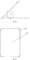
Fig. 2B , O is a vertex of an angle ∠ AOB, and lines OD and OE are two sides of the angle ∠ AOB. An arc

- Original right-angle corners of the
display screen 201 are cut into arc shapes respectively to form the fourscreen corners 2011. As shown inFig. 2C , thedisplay screen 201 has four right-angled corners originally. The fourrounded corners 2011 are formed by cutting the four right-angled corners based on the arcs shown inFig. 2C . - In addition, the process of cutting the display screen may be various, including a laser cutting process, a water cutting process, and the like, and this embodiment is not limited thereto.
- As shown in
Fig. 2A , the fourscreen corners 2011 correspond to the fourbezel corners 2021 respectively, which specifically refers to that: an upper left corner of thedisplay screen 201 corresponds to an upper left corner of thebezel 202, a lower left corner of thedisplay screen 201 corresponds to a lower left corner of thebezel 202, an upper right corner of thedisplay screen 201 corresponds to an upper right corner of thebezel 202, and a lower right corner of thedisplay screen 201 corresponds to a lower right corner of thebezel 202. - In an embodiment of the present disclosure, a distance between vertexes of the
screen corners 2011 andbezel corners 2021 corresponding to each other is not less than a preset distance. - The preset distance refers a minimum distance capable of protecting the screen centers adequately. It could be considered that when the distance between the vertexes is less than the preset distance, the width of the bezel outside of the screen corners is too small, such that the screen corners are susceptible to have abrasion.
- The vertex of the rounded corner refers to a midpoint of the arc for forming the rounded corner, i.e. a point on the arc and with the same distance from the two ends of the arc. Taking the upper left corner as an example, an enlarged view of the
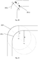
screen corner 2011 and thebezel corner 2021 is shown inFig. 2D . Points E and F are the vertexes of thebezel corner 2021 and thescreen corner 2011, respectively. A distance L between the two vertices E and F is a specified distance which is not less than the preset distance. - In the related arts, the four screen corners of the display screen are all right-angled corners, the four bezel corners of the bezel are rounded corners, and the widths of the four sides of the bezel are determined by the respective specified distance between the vertexes of the screen corners and bezel corners corresponding to each other. However, in order to adequately protect each screen angle, each specified distance should not be less than the preset distance, which causes that the widths of the four sides of the bezel cannot be reduced unrestrictedly.
- In the embodiment, the four
screen corners 2011 of thedisplay screen 201 are set to be rounded so that the vertices of the fourscreen corners 2011 are closer to the center of thedisplay screen 201 while the size of thedisplay screen 201 is guaranteed to be constant. Even if the widths of the four sides of the bezel are reduced, it is ensured that the specified distance between the vertex of thecorresponding screen corner 2011 and the vertex of the correspondingbezel corner 2021 is not less than the preset distance, and the effect of protecting thedisplay screen 201 may also be achieved. - It should be noted that the electronic device may be a smart phone, a television, a tablet, and the like, and the embodiment is not limited thereto.
- With the electronic device provided by the embodiments, by setting the four screen corners of the display screen and the four bezel corners of the bezel to be the rounded corners, the vertexes of the four
screen corners 2011 are closer to the center of thedisplay screen 201 under a condition that the size of the display screen is constant, and the widths of the four sides of the bezel can be reduced under a condition that the specific distance between the vertexes of the bezel corners and screen corners corresponding to each other is not less than the preset distance, therefore narrowing the bezel of the electronic device. In addition, by configuring the rounded screen corners and the narrow bezel, the aesthetics of electronic equipment is enhanced greatly. - In a possible implementation, in order to enhance the aesthetics of electronic equipment, a curvature of each of the four
screen corners 2011 is equal to a curvature of each of the fourbezel corners 2021. - The curvature is configured to indicate a degree of bending of the arc. The greater the curvature, the greater the degree of bending of the arc is. The curvature of the arc is inversely proportional to the radius of the arc. In order to ensure that the curvature of a
screen corner 2011 is equal to the curvature of abezel corner 2021, it is needed to ensure the radius of an arc of thescreen corner 2011 is equal to the radius of an arc of thebezel corner 2021. - As shown in
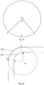
Fig. 2E , O1 is a center of a circle for the arc of thescreen corner bezel corner 2021. The radiuses for the arc of thescreen corner 2011 and for the arc of thebezel corner 2021 both are R0, so the curvature of thescreen corner 2011 is equal to the curvature of thebezel corner 2021. - In a possible implementation, a central angle corresponding to each of the four
screen corners 2011 is equal to a central angle corresponding to each of the fourbezel corners 2021. - For the arc, the central angle refers to an angle having a vertex as the center of the circle for the arc and having two lines passing through two ends of the arc. As shown in
Fig. 2F , an arc
circle 03, apoint 03 is the center of the circle, and the central angle corresponding to the arc
- The central angle corresponding to each of the four
screen corners 2011 is equal to the central angle corresponding to each of the fourbezel corners 2021, which refers to that: the center of the circle for the arc of thecorresponding screen corner 2011 is the same with the center of the circle for the arc of the correspondingbezel corner 2021, extension lines of two lines of the central angle for thecorresponding screen corner 2011 are coincided with extension lines of two lines of the central angle for thecorresponding bezel corner 2021 respectively. As shown inFig. 2G , the central angle for thecorresponding screen corner 2011 and the central angle for thecorresponding bezel corner 2021 both are ∠ MO4N. - In a possible implementation, the
display screen 201 is a liquid crystal display screen. The liquid crystal display screen is provided with a plurality of pixel electrodes. In cutting the liquid crystal display screen, it is not necessary to provide a pixel electrode for the portion to be cut off on the liquid crystal display screen. - Alternatively, the display screen may be another type of display screen such as a plasma display screen, which is not limited in this embodiment.
- All of the above alternative implementations may be used in any combination to form alternative embodiments of the present disclosure and are not further described herein.
-
Fig. 3A is a flow chart showing a display method according to an example embodiment of the present disclosure. As shown inFig. 3A , the method is performed by the electronic device shown inFig. 3B and includes followings. - In
step 301, a preset floating layer is acquired. The preset floating layer includes a first portion and a second portion. The first portion is black, and the second portion is transparent. A dividing line between the first portion and the second portion is an arc-shaped smooth curve. - A length of the preset floating layer is equal to a length of the display screen, and a width of the preset floating layer is equal to a width of the display screen. The length of the display screen refers to the distance between the left side and the right side of the display screen, and the width of the display screen refers to the distance between the upper side and the lower side of the display screen. As shown in
Fig. 3B , thedisplay screen 201 has a length L1 and a width L2. - The preset floating layer may be provided in the electronic device by a technician, or, the preset floating layer may be created by the electronic device. For example, the electronic device can acquire the size information of the display screen, in which the size information includes the length and the width of the display screen, the radius and the arc length of each screen corner of the display screen, and the like; and then the electronic device can create the preset floating layer based on the size information such that the length and the width of the preset floating layer are equal to the length and the width of the display screen respectively, and divides the preset floating layer into two portions according to the radius and the arc length of each screen corner, and the like, in which the first portion is set as a black floating layer, and the second portion is set as a transparent floating layer so that the dividing line of the first portion and the second portion is the arc-shaped smooth curve and is located at the inner side of edges of the display screen. So when the preset floating layer is displayed, the first portion of the preset floating layer can cover the content displayed on the edges of the display screen.
- The four angles of the preset floating layer may be the right-angles or rounded angles, and this embodiment is not limited thereto.
- In a possible implementation, the dividing line is located at the inner side of the edges of the rounded screen corners of the display screen.
- As shown in
Fig. 3C , taking the upper left corner as an example, when the upper left corner of thedisplay screen 201 is cut into the rounded corner from the right-angled corner, the edge of the upper left corner is not smooth due to a limitation of the cutting process, such that a plurality of pixels on the edge of the upper left corner are formed as serrated. The edge of the page displayed may be not smooth when the display is performed by thedisplay screen 201, affecting the user's observation. The dividing line between the first portion (denoted by the dotted line) and the second portion of the preset floating layer as shown inFig. 3C is located at the inner side of the serrated edges of the display screen. When the display screen displays the page, the first portion may obscure the content displayed at the serrated edges. - In
step 302, when a page is displayed, the preset floating layer is displayed on a top of the page so that the first portion shades the page. - The preset floating layer can be set on the top by the electronic device. When the electronic device displays any page any time, the preset floating layer may be shown on the top of the page, thus ensuring that the first portion of the floating layer covers the region overlapped with the first portion on the page but does not cover the region overlapped with the second portion. The user can only see the region overlapped with the second portion when viewing the page, and the edges of this region are smooth.
- As shown in
Fig. 3D , the black region is the first portion, which can cover the saw-teeth at the rounded corners of the display screen as shown inFig. 3C . The page saw by the user is located at the region of the second portion when the page is displayed, i.e. the region within the dividing line. The boundary of this region is the smooth curve, and the boundary of the page displayed to the user is also smooth. - When the page is displayed, the electronic device controls the pixels corresponding to first portion on the display screen to be black.
- Since the size of the preset floating layer is in the accordance with the size of the display screen, and the preset floating layer and the display screen can correspond to each other, a part of the pixels on the display screen will correspond to the first portion and another part of the pixels on the display screen will correspond to the second portion. The pixels corresponding to the first portion on the display screen are located at the outer side of the dividing line of the preset floating layer.
- In the embodiment, in order to ensure that the first portion obscures the displayed page, in actual operation, the electronic device can control the pixels corresponding to the first portion on the display screen to be black, that is, to control the brightness of these pixels to be 0, so as to achieve the effect of blocking the page displayed on the edges of the four screen corners.
- With the method provided in embodiments, the preset floating layer is acquired, in which the preset floating layer includes the first portion and the second portion, the first portion is the black floating layer, the second portion is the transparent floating layer, and the dividing line of the black floating layer and the transparent floating layer is the arc-shaped smooth curve; and the preset floating layer is displayed on the top of the page when the page is displayed, the black floating layer of the preset floating layer will block the rounded corners of the page and the not-smooth part on the displayed page is covered, so that the rounded corners on the page become smooth and the display effect is improved.
- The edges of the display screen in the electronic device shown in
Fig. 3A are not smooth. The screen corners after being cut are very rough due to the limitation of the cutting process when the four original right-angled corners are cut into the rounded corners. The pixels at the edges are box-shaped, resulting in the edges of the display screen are serrated and not smooth. When the page is to be displayed, the serrated edges of the display screen will be displayed, which will give the user a bad visual effect. - In order to eliminate the non-smoothness of the edges caused by the limitation of the cutting process, in the present embodiment, the preset floating layer is displayed on the top of the page, the preset floating layer is divided into two parts, one part is the black floating layer configured to hide a part on the page where the edges are not smooth, another part is the transparent floating layer configured to display the page, and the dividing line between the black floating layer and the transparent floating layer is the smooth curve, so the region overlapped with the second portion on the page may be displayed to the user and the edges of this region are smooth, thus solving the problem that the edges of the displayed page are not smooth.
-
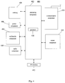
Fig. 4 is a block diagram illustrating anelectronic device 400 according to an exemplary embodiment of the present disclosure. For example, theelectronic device 400 may be a mobile phone, a computer, a digital broadcasting terminal, a messaging device, a game console, a tablet device, a medical device, fitness equipment, a Personal Digital Assistant PDA, and the like - Referring to
Fig. 4 , theelectronic device 400 may include the following one or more components: aprocessing component 402, amemory 404, apower component 406, amultimedia component 408, anaudio component 410, an Input/Output (I/O)interface 412, asensor component 414, and acommunication component 416. - The
processing component 402 typically controls overall operations of theelectronic device 400, such as the operations associated with display, telephone calls, data communications, camera operations, and recording operations. Theprocessing component 402 may include one ormore processors 420 to execute instructions to perform all or part of the steps in the above described methods. Moreover, theprocessing component 402 may include one or more modules which facilitate the interaction between theprocessing component 402 and other components. For instance, theprocessing component 402 may include a multimedia module to facilitate the interaction between themultimedia component 408 and theprocessing component 402. - The
memory 404 is configured to store various types of data to support the operation of theelectronic device 400. Examples of such data include instructions for any applications or methods operated on theelectronic device 400, contact data, phonebook data, messages, pictures, video, etc. Thememory 404 may be implemented using any type of volatile or non-volatile memory devices, or a combination thereof, such as a static random access memory (SRAM), an electrically erasable programmable read-only memory (EEPROM), an erasable programmable read-only memory (EPROM), a programmable read-only memory (PROM), a read-only memory (ROM), a magnetic memory, a flash memory, a magnetic or optical disk. - The
power component 406 provides power to various components of theelectronic device 400. Thepower component 406 may include a power management system, one or more power sources, and any other components associated with the generation, management, and distribution of power in theelectronic device 400. - The
multimedia component 408 includes a screen providing an output interface between theelectronic device 400 and the user, and the four corner of the screen are rounded. In some embodiments, the screen may include a liquid crystal display (LCD) and a press panel (TP). If the screen includes the press panel, the screen may be implemented as a press screen to receive input signals from the user. The press panel includes one or more press sensors to sense presses, swipes, and other gestures on the press panel. The press sensors may not only sense a boundary of a press or swipe action, but also sense a duration time and a pressure associated with the press or swipe action. In some embodiments, themultimedia component 408 includes a front camera and/or a rear camera. The front camera and/or the rear camera may receive external multimedia data while theelectronic device 400 is in an operation mode, such as a photographing mode or a video mode. Each of the front camera and the rear camera may be a fixed optical lens system or have focus and optical zoom capability. - The
audio component 410 is configured to output and/or input audio signals. For example, theaudio component 410 includes a microphone (MIC) configured to receive an external audio signal when theelectronic device 400 is in an operation mode, such as a call mode, a recording mode, and a voice recognition mode. The received audio signal may be further stored in thememory 404 or transmitted via thecommunication component 416. In some embodiments, theaudio component 410 further includes a speaker to output audio signals. - The I/
O interface 412 provides an interface for theprocessing component 402 and peripheral interface modules, such as a keyboard, a click wheel, buttons, and the like. The buttons may include, but are not limited to, a home button, a volume button, a starting button, and a locking button. - The
sensor component 414 includes one or more sensors to provide status assessments of various aspects of theelectronic device 400. For instance, thesensor component 414 may detect an open/closed status of theelectronic device 400 and relative positioning of components (e.g. the display and the keypad of theelectronic device 400. Thesensor component 414 may also detect a change in position of theelectronic device 400 or of a component in theelectronic device 400, a presence or absence of user contact with theelectronic device 400, an orientation or an acceleration/deceleration of theelectronic device 400, and a change in temperature of theelectronic device 400. Thesensor component 414 may include a proximity sensor configured to detect the presence of nearby objects without any physical contact. Thesensor component 414 may also include a light sensor, such as a CMOS or CCD image sensor, for use in imaging applications. In some embodiments, thesensor component 414 may also include an accelerometer sensor, a gyroscope sensor, a magnetic sensor, a pressure sensor, or a temperature sensor. - The
communication component 416 is configured to facilitate wired or wireless communication between theelectronic device 400 and other devices. Theelectronic device 400 can access a wireless network based on a communication standard, such as WIFI, 2G, or 3G, or a combination thereof. In one exemplary embodiment, thecommunication component 416 receives a broadcast signal or broadcast associated information from an external broadcast management system via a broadcast channel. In one exemplary embodiment, thecommunication component 416 further includes a near field communication (NFC) module to facilitate short-range communications. For example, the NFC module may be implemented based on a radio frequency identification (RFID) technology, an infrared data association (IrDA) technology, an ultra-wideband (UWB) technology, a Bluetooth (BT) technology, and other technologies. - In exemplary embodiments, the
electronic device 400 may be implemented with one or more application specific integrated circuits (ASICs), digital signal processors (DSPs), digital signal processing devices (DSPDs), programmable logic devices (PLDs), field programmable gate arrays (FPGAs), controllers, micro-controllers, microprocessors, or other electronic components, for performing the above described methods. - In exemplary embodiments, there is also provided a non-transitory computer readable storage medium including instructions, such as the
memory 404 including instructions. The instructions may be performed by theprocessor 420 of theelectronic device 400 so as to realize the method for generating information. For example, the non-transitory computer-readable storage medium may be a ROM, a RAM, a CD-ROM, a magnetic tape, a floppy disc, an optical data storage device, and the like. - Other embodiments of the disclosure will be apparent to those skilled in the art from consideration of the specification and practice of the disclosure disclosed here. This application is intended to cover any variations, uses, or adaptations of the disclosure following the general principles thereof and including such departures from the present disclosure as come within known or customary practice in the art.
Claims (15)
- An electronic device, at least comprising a display screen (201) and a bezel (202), wherein the bezel (202) surrounds sides of the display screen (201);
the display screen (201) has four screen corners (2011), and the four screen corners (2011) are rounded;
the bezel (202) has four sides (2022; 2023; 2024; 2025), any one of the four sides (2022; 2023; 2024; 2025) intersects two of further three sides of the four sides (2022; 2023; 2024; 2025) respectively and is in parallel with another one of the further three sides to form four bezel corners (2021);
the four bezel corners (2021) correspond to the four screen corners (2011) respectively, and the four bezel corners (2021) are rounded;
a distance (L) between vertexes (E; F) of the bezel corners (2021) and screen corners (2011) corresponding to each other is not less than a preset distance. - The electronic device according to claim 1, wherein a curvature of each of the four screen corners (2011) is equal to a curvature of each the four bezel corners (2021).
- The electronic device according to claim 1, wherein a central angle corresponding to each of the four screen corners (2011) is equal to a central angle corresponding to each of the four bezel corners (2021).
- The electronic device according to claim 1, wherein the display screen is a liquid crystal display screen.
- The electronic device according to any one of claims 1 to 4, wherein original right-angle corners of the display screen are cut into arc shapes respectively to form the four screen corners (2011).
- The electronic device according to claim 5 when based on claim 4, wherein the liquid crystal display screen is provided with a plurality of pixel electrodes, and there is no pixel electrode on a part to be cut off of the liquid crystal display screen.
- The electronic device according to any of claims 5-6, wherein original right-angle corners of the display screen are cut by a cutting process selected from a group consisting of: a laser cutting process and a water cutting process.
- A display method, wherein the method is performed by the electronic device according to any one of claims 1 to 7 and comprises:acquiring (301) a preset floating layer comprising a first portion and a second portion, wherein the first portion is black, the second portion is transparent, a dividing line between the first portion and the second portion is an arc-shaped smooth curve;when a page is displayed, displaying (302) the preset floating layer on a top of the page so that the first portion shades the page displayed on edges of the four screen corners of the display screen.
- The method according to claim 8, further comprising:creating the preset floating layer according to size information of the display screen.
- The method according to claim 9, wherein the size information comprises: a length of the display screen, a width of the display screen, a radius of each screen corner of the display screen and a length of an arc of each screen corner of the display screen.
- The method according to claim 8, wherein when a page is displayed, displaying (302) the preset floating layer on a top of the page comprises:when the page is displayed, controlling pixels corresponding to the first portion on the display screen to be black.
- The method according to claim 11, wherein controlling pixels corresponding to the first portion on the display screen to be black comprises:controlling brightness values of the pixels to be zero.
- The method according to claim 8, wherein the dividing line is located at the inner side of the edges of the rounded screen corners of the display screen.
- The method according to claim 8, wherein a length of the preset floating layer is equal to a length of the display screen and a width of the preset floating layer is equal to a width of the display screen.
- A computer readable storage medium, comprising a computer program for executing a display method according to any of claims 8-14.
Applications Claiming Priority (1)
| Application Number | Priority Date | Filing Date | Title |
|---|---|---|---|
| CN201610860812.2A CN106527580B (en) | 2016-09-28 | 2016-09-28 | Electronic device and display method |
Publications (1)
| Publication Number | Publication Date |
|---|---|
| EP3301539A1 true EP3301539A1 (en) | 2018-04-04 |
Family
ID=58344558
Family Applications (1)
| Application Number | Title | Priority Date | Filing Date |
|---|---|---|---|
| EP17173523.6A Ceased EP3301539A1 (en) | 2016-09-28 | 2017-05-30 | Electronic device and display method |
Country Status (7)
| Country | Link |
|---|---|
| US (1) | US20180088393A1 (en) |
| EP (1) | EP3301539A1 (en) |
| JP (1) | JP2019500631A (en) |
| KR (1) | KR20190003629A (en) |
| CN (1) | CN106527580B (en) |
| RU (1) | RU2690748C1 (en) |
| WO (1) | WO2018058813A1 (en) |
Families Citing this family (20)
| Publication number | Priority date | Publication date | Assignee | Title |
|---|---|---|---|---|
| CN106843389B (en) * | 2017-01-09 | 2022-08-05 | Oppo广东移动通信有限公司 | Electronic device |
| KR20180098466A (en) * | 2017-02-25 | 2018-09-04 | 삼성전자주식회사 | Electronic device comprising display having rounded corners |
| JP6907036B2 (en) * | 2017-06-12 | 2021-07-21 | 株式会社ジャパンディスプレイ | Display device |
| CN107315501B (en) * | 2017-06-30 | 2020-07-03 | 上海中航光电子有限公司 | A display panel and display device |
| CN107103893B (en) | 2017-06-30 | 2019-09-27 | 上海天马有机发光显示技术有限公司 | A Method for Improving the Display Effect of the Edge of a Circular Display |
| CN107391073B (en) * | 2017-07-26 | 2020-07-10 | 北京小米移动软件有限公司 | Display modules and electronic equipment |
| CN107643885A (en) * | 2017-10-13 | 2018-01-30 | 北京小米移动软件有限公司 | Display screen, method for displaying image and terminal and storage medium |
| CN107817918B (en) * | 2017-10-18 | 2021-03-16 | 上海闻泰信息技术有限公司 | Display device, display adjustment method, and mobile terminal |
| CN107656791A (en) * | 2017-10-18 | 2018-02-02 | 珠海市魅族科技有限公司 | Method, terminal device, computer installation and the storage medium of display |
| CN107797785A (en) * | 2017-10-24 | 2018-03-13 | 深圳天珑无线科技有限公司 | Effect screen optimization method, mobile terminal and storage device |
| USD884743S1 (en) * | 2018-02-11 | 2020-05-19 | Beijing Xiaomi Mobile Software Co., Ltd. | Foldable screen |
| CN109375978A (en) * | 2018-10-17 | 2019-02-22 | 奇酷互联网络科技(深圳)有限公司 | Display methods, computer equipment and the storage medium of fillet screen |
| CN113412470B (en) * | 2019-04-23 | 2023-09-08 | 华为技术有限公司 | Methods and devices for processing layers |
| CN112698543B (en) * | 2019-10-23 | 2025-09-09 | 海信视像科技股份有限公司 | Electronic equipment |
| KR102741263B1 (en) * | 2020-04-13 | 2024-12-11 | 삼성디스플레이 주식회사 | Display device |
| CN114101924B (en) * | 2020-08-25 | 2024-04-26 | 大族激光科技产业集团股份有限公司 | A process for laser cutting screen |
| CN112788859B (en) * | 2021-01-21 | 2022-04-01 | 上海望友信息科技有限公司 | Shielding frame steel mesh opening method and device, electronic equipment and storage medium |
| CN113253966A (en) * | 2021-07-07 | 2021-08-13 | 湖北亿咖通科技有限公司 | User interface fillet display method and device, electronic equipment and storage medium |
| CN117012114B (en) * | 2023-07-28 | 2026-04-24 | 武汉天马微电子有限公司 | Display panel and display device |
| CN119439551A (en) * | 2023-07-31 | 2025-02-14 | 北京小米移动软件有限公司 | Display modules and electronic devices |
Citations (2)
| Publication number | Priority date | Publication date | Assignee | Title |
|---|---|---|---|---|
| US20140139771A1 (en) * | 2012-11-19 | 2014-05-22 | Lg Display Co., Ltd. | Display device |
| US20150211707A1 (en) * | 2012-07-09 | 2015-07-30 | Sharp Kabushiki Kaisha | Display device |
Family Cites Families (8)
| Publication number | Priority date | Publication date | Assignee | Title |
|---|---|---|---|---|
| EP2562591A4 (en) * | 2010-04-19 | 2014-08-20 | Sharp Kk | DISPLAY DEVICE AND METHOD FOR MANUFACTURING THE SAME |
| KR102062324B1 (en) * | 2013-01-15 | 2020-01-03 | 엘지전자 주식회사 | Organic light emitting device and display apparatus with the same |
| KR102131825B1 (en) * | 2013-03-20 | 2020-07-09 | 엘지전자 주식회사 | Foldable display device providing adaptive touch sensitive region and method for controlling the same |
| CN103513925B (en) * | 2013-07-02 | 2016-08-17 | 中体彩科技发展有限公司 | A kind of dynamic effect display device |
| JP2015064845A (en) * | 2013-09-26 | 2015-04-09 | 沖電気工業株式会社 | Display control method, system, device, and program |
| KR20150039024A (en) * | 2013-10-01 | 2015-04-09 | 엘지전자 주식회사 | Mobile terminal |
| CN103763414A (en) * | 2014-01-08 | 2014-04-30 | 孟祥吉 | Design of handheld mobile terminal with maximized screen |
| CN104090734B (en) * | 2014-06-03 | 2017-12-29 | 联想(北京)有限公司 | A kind of information processing method and electronic equipment |
-
2016
- 2016-09-28 CN CN201610860812.2A patent/CN106527580B/en active Active
- 2016-12-20 RU RU2018111954A patent/RU2690748C1/en active
- 2016-12-20 WO PCT/CN2016/111040 patent/WO2018058813A1/en not_active Ceased
- 2016-12-20 KR KR1020187034214A patent/KR20190003629A/en not_active Ceased
- 2016-12-20 JP JP2017541001A patent/JP2019500631A/en active Pending
-
2017
- 2017-05-30 EP EP17173523.6A patent/EP3301539A1/en not_active Ceased
- 2017-07-24 US US15/657,215 patent/US20180088393A1/en not_active Abandoned
Patent Citations (2)
| Publication number | Priority date | Publication date | Assignee | Title |
|---|---|---|---|---|
| US20150211707A1 (en) * | 2012-07-09 | 2015-07-30 | Sharp Kabushiki Kaisha | Display device |
| US20140139771A1 (en) * | 2012-11-19 | 2014-05-22 | Lg Display Co., Ltd. | Display device |
Non-Patent Citations (1)
| Title |
|---|
| GADGET HACKS: "How to Get Rounded Screen Corners on a Samsung Galaxy S3", 23 May 2013 (2013-05-23), XP054977863, Retrieved from the Internet <URL:https://www.youtube.com/watch?v=PTNKU1jvEyw> [retrieved on 20171110] * |
Also Published As
| Publication number | Publication date |
|---|---|
| JP2019500631A (en) | 2019-01-10 |
| WO2018058813A1 (en) | 2018-04-05 |
| RU2690748C1 (en) | 2019-06-05 |
| CN106527580A (en) | 2017-03-22 |
| US20180088393A1 (en) | 2018-03-29 |
| CN106527580B (en) | 2020-08-04 |
| KR20190003629A (en) | 2019-01-09 |
Similar Documents
| Publication | Publication Date | Title |
|---|---|---|
| EP3301539A1 (en) | Electronic device and display method | |
| US10788978B2 (en) | Method and apparatus for displaying interface and storage medium | |
| EP3179711B1 (en) | Method and apparatus for preventing photograph from being shielded | |
| CN109784255B (en) | Neural network training method and device and recognition method and device | |
| EP2927787B1 (en) | Method and device for displaying picture | |
| EP3099075B1 (en) | Method and device for processing identification of video file | |
| EP3913476A1 (en) | Image display method and device, electronic device, and storage medium | |
| EP3040966A2 (en) | Liquid crystal display color adjustment method and device | |
| CN108900693B (en) | Window display method and device | |
| CN109285126B (en) | Image processing method and device, electronic equipment and storage medium | |
| US11372516B2 (en) | Method, device, and storage medium for controlling display of floating window | |
| CN111243011A (en) | Key point detection method and device, electronic equipment and storage medium | |
| EP3770859B1 (en) | Image processing method, image processing apparatus, and storage medium | |
| US20180204500A1 (en) | Method and device for enhancing contrast | |
| EP2921969A1 (en) | Method and apparatus for centering and zooming webpage and electronic device | |
| CN108900903B (en) | Video processing method and device, electronic equipment and storage medium | |
| EP3474118A1 (en) | Controlling field of view | |
| EP3032482A1 (en) | Page display method and apparatus | |
| US20150371367A1 (en) | Method and terminal device for retargeting images | |
| EP3015968B1 (en) | Method for image deletion and device thereof | |
| CN112463084A (en) | Split screen display method and device, terminal equipment and computer readable storage medium | |
| US20210120276A1 (en) | Screen display device, method and device for controlling screen display and storage medium | |
| US9619016B2 (en) | Method and device for displaying wallpaper image on screen | |
| CN117891383A (en) | Method, device, equipment and storage medium for highlighting local area of touch screen | |
| CN107680096A (en) | Image processing method and device |
Legal Events
| Date | Code | Title | Description |
|---|---|---|---|
| PUAI | Public reference made under article 153(3) epc to a published international application that has entered the european phase |
Free format text: ORIGINAL CODE: 0009012 |
|
| STAA | Information on the status of an ep patent application or granted ep patent |
Free format text: STATUS: THE APPLICATION HAS BEEN PUBLISHED |
|
| AK | Designated contracting states |
Kind code of ref document: A1 Designated state(s): AL AT BE BG CH CY CZ DE DK EE ES FI FR GB GR HR HU IE IS IT LI LT LU LV MC MK MT NL NO PL PT RO RS SE SI SK SM TR |
|
| AX | Request for extension of the european patent |
Extension state: BA ME |
|
| STAA | Information on the status of an ep patent application or granted ep patent |
Free format text: STATUS: REQUEST FOR EXAMINATION WAS MADE |
|
| 17P | Request for examination filed |
Effective date: 20181003 |
|
| RBV | Designated contracting states (corrected) |
Designated state(s): AL AT BE BG CH CY CZ DE DK EE ES FI FR GB GR HR HU IE IS IT LI LT LU LV MC MK MT NL NO PL PT RO RS SE SI SK SM TR |
|
| STAA | Information on the status of an ep patent application or granted ep patent |
Free format text: STATUS: EXAMINATION IS IN PROGRESS |
|
| 17Q | First examination report despatched |
Effective date: 20190603 |
|
| STAA | Information on the status of an ep patent application or granted ep patent |
Free format text: STATUS: THE APPLICATION HAS BEEN REFUSED |
|
| 18R | Application refused |
Effective date: 20210628 |