EP3301494A1 - Optical scanning apparatus and image forming apparatus - Google Patents
Optical scanning apparatus and image forming apparatus Download PDFInfo
- Publication number
- EP3301494A1 EP3301494A1 EP17190514.4A EP17190514A EP3301494A1 EP 3301494 A1 EP3301494 A1 EP 3301494A1 EP 17190514 A EP17190514 A EP 17190514A EP 3301494 A1 EP3301494 A1 EP 3301494A1
- Authority
- EP
- European Patent Office
- Prior art keywords
- mirror
- reflection mirror
- supporting
- leaf spring
- optical scanning
- Prior art date
- Legal status (The legal status is an assumption and is not a legal conclusion. Google has not performed a legal analysis and makes no representation as to the accuracy of the status listed.)
- Withdrawn
Links
- 230000003287 optical effect Effects 0.000 title claims abstract description 91
- 239000000853 adhesive Substances 0.000 claims abstract description 78
- 230000001070 adhesive effect Effects 0.000 claims abstract description 78
- 238000012546 transfer Methods 0.000 claims description 26
- 230000003014 reinforcing effect Effects 0.000 claims description 3
- 238000009434 installation Methods 0.000 description 5
- 230000001133 acceleration Effects 0.000 description 4
- 238000013461 design Methods 0.000 description 4
- 239000003086 colorant Substances 0.000 description 3
- 238000000034 method Methods 0.000 description 3
- 230000006641 stabilisation Effects 0.000 description 3
- 238000011105 stabilization Methods 0.000 description 3
- 230000000694 effects Effects 0.000 description 2
- 230000001965 increasing effect Effects 0.000 description 2
- 238000003825 pressing Methods 0.000 description 2
- 230000035939 shock Effects 0.000 description 2
- 238000005452 bending Methods 0.000 description 1
- 230000033228 biological regulation Effects 0.000 description 1
- 230000015572 biosynthetic process Effects 0.000 description 1
- 239000000470 constituent Substances 0.000 description 1
- 230000001276 controlling effect Effects 0.000 description 1
- 230000003247 decreasing effect Effects 0.000 description 1
- 230000006866 deterioration Effects 0.000 description 1
- 238000007599 discharging Methods 0.000 description 1
- 230000002708 enhancing effect Effects 0.000 description 1
- 238000003384 imaging method Methods 0.000 description 1
- 238000003780 insertion Methods 0.000 description 1
- 230000037431 insertion Effects 0.000 description 1
- 238000012423 maintenance Methods 0.000 description 1
- 238000004519 manufacturing process Methods 0.000 description 1
- 239000000463 material Substances 0.000 description 1
- 238000012986 modification Methods 0.000 description 1
- 230000004048 modification Effects 0.000 description 1
- 230000002093 peripheral effect Effects 0.000 description 1
- 230000002265 prevention Effects 0.000 description 1
- 230000001105 regulatory effect Effects 0.000 description 1
- 239000004065 semiconductor Substances 0.000 description 1
- 238000007711 solidification Methods 0.000 description 1
- 230000008023 solidification Effects 0.000 description 1
- 230000000087 stabilizing effect Effects 0.000 description 1
- 238000011144 upstream manufacturing Methods 0.000 description 1
Images




Classifications
-
- H—ELECTRICITY
- H04—ELECTRIC COMMUNICATION TECHNIQUE
- H04N—PICTORIAL COMMUNICATION, e.g. TELEVISION
- H04N1/00—Scanning, transmission or reproduction of documents or the like, e.g. facsimile transmission; Details thereof
- H04N1/024—Details of scanning heads ; Means for illuminating the original
- H04N1/028—Details of scanning heads ; Means for illuminating the original for picture information pick-up
- H04N1/02815—Means for illuminating the original, not specific to a particular type of pick-up head
- H04N1/0282—Using a single or a few point light sources, e.g. a laser diode
- H04N1/0283—Using a single or a few point light sources, e.g. a laser diode in combination with a light deflecting element, e.g. a rotating mirror
-
- G—PHYSICS
- G02—OPTICS
- G02B—OPTICAL ELEMENTS, SYSTEMS OR APPARATUS
- G02B7/00—Mountings, adjusting means, or light-tight connections, for optical elements
- G02B7/18—Mountings, adjusting means, or light-tight connections, for optical elements for prisms; for mirrors
- G02B7/182—Mountings, adjusting means, or light-tight connections, for optical elements for prisms; for mirrors for mirrors
- G02B7/1821—Mountings, adjusting means, or light-tight connections, for optical elements for prisms; for mirrors for mirrors for rotating or oscillating mirrors
-
- G—PHYSICS
- G02—OPTICS
- G02B—OPTICAL ELEMENTS, SYSTEMS OR APPARATUS
- G02B26/00—Optical devices or arrangements for the control of light using movable or deformable optical elements
- G02B26/08—Optical devices or arrangements for the control of light using movable or deformable optical elements for controlling the direction of light
- G02B26/10—Scanning systems
- G02B26/12—Scanning systems using multifaceted mirrors
- G02B26/125—Details of the optical system between the polygonal mirror and the image plane
-
- G—PHYSICS
- G02—OPTICS
- G02B—OPTICAL ELEMENTS, SYSTEMS OR APPARATUS
- G02B26/00—Optical devices or arrangements for the control of light using movable or deformable optical elements
- G02B26/08—Optical devices or arrangements for the control of light using movable or deformable optical elements for controlling the direction of light
- G02B26/10—Scanning systems
-
- G—PHYSICS
- G02—OPTICS
- G02B—OPTICAL ELEMENTS, SYSTEMS OR APPARATUS
- G02B26/00—Optical devices or arrangements for the control of light using movable or deformable optical elements
- G02B26/08—Optical devices or arrangements for the control of light using movable or deformable optical elements for controlling the direction of light
- G02B26/10—Scanning systems
- G02B26/12—Scanning systems using multifaceted mirrors
-
- G—PHYSICS
- G02—OPTICS
- G02B—OPTICAL ELEMENTS, SYSTEMS OR APPARATUS
- G02B7/00—Mountings, adjusting means, or light-tight connections, for optical elements
- G02B7/18—Mountings, adjusting means, or light-tight connections, for optical elements for prisms; for mirrors
- G02B7/182—Mountings, adjusting means, or light-tight connections, for optical elements for prisms; for mirrors for mirrors
-
- G—PHYSICS
- G03—PHOTOGRAPHY; CINEMATOGRAPHY; ANALOGOUS TECHNIQUES USING WAVES OTHER THAN OPTICAL WAVES; ELECTROGRAPHY; HOLOGRAPHY
- G03G—ELECTROGRAPHY; ELECTROPHOTOGRAPHY; MAGNETOGRAPHY
- G03G15/00—Apparatus for electrographic processes using a charge pattern
- G03G15/04—Apparatus for electrographic processes using a charge pattern for exposing, i.e. imagewise exposure by optically projecting the original image on a photoconductive recording material
- G03G15/04036—Details of illuminating systems, e.g. lamps, reflectors
-
- G—PHYSICS
- G03—PHOTOGRAPHY; CINEMATOGRAPHY; ANALOGOUS TECHNIQUES USING WAVES OTHER THAN OPTICAL WAVES; ELECTROGRAPHY; HOLOGRAPHY
- G03G—ELECTROGRAPHY; ELECTROPHOTOGRAPHY; MAGNETOGRAPHY
- G03G15/00—Apparatus for electrographic processes using a charge pattern
- G03G15/04—Apparatus for electrographic processes using a charge pattern for exposing, i.e. imagewise exposure by optically projecting the original image on a photoconductive recording material
- G03G15/0409—Details of projection optics
-
- H—ELECTRICITY
- H04—ELECTRIC COMMUNICATION TECHNIQUE
- H04N—PICTORIAL COMMUNICATION, e.g. TELEVISION
- H04N2201/00—Indexing scheme relating to scanning, transmission or reproduction of documents or the like, and to details thereof
- H04N2201/0077—Types of the still picture apparatus
- H04N2201/0094—Multifunctional device, i.e. a device capable of all of reading, reproducing, copying, facsimile transception, file transception
-
- H—ELECTRICITY
- H04—ELECTRIC COMMUNICATION TECHNIQUE
- H04N—PICTORIAL COMMUNICATION, e.g. TELEVISION
- H04N2201/00—Indexing scheme relating to scanning, transmission or reproduction of documents or the like, and to details thereof
- H04N2201/024—Indexing scheme relating to scanning, transmission or reproduction of documents or the like, and to details thereof deleted
- H04N2201/02452—Arrangements for mounting or supporting elements within a scanning head
- H04N2201/02454—Element mounted or supported
- H04N2201/0246—Mirror, reflecting element or beam splitter
-
- H—ELECTRICITY
- H04—ELECTRIC COMMUNICATION TECHNIQUE
- H04N—PICTORIAL COMMUNICATION, e.g. TELEVISION
- H04N2201/00—Indexing scheme relating to scanning, transmission or reproduction of documents or the like, and to details thereof
- H04N2201/024—Indexing scheme relating to scanning, transmission or reproduction of documents or the like, and to details thereof deleted
- H04N2201/02452—Arrangements for mounting or supporting elements within a scanning head
- H04N2201/02466—Mounting or supporting method
- H04N2201/02477—Mounting or supporting method using elastic means, e.g. springs
Definitions
- the present invention relates to an optical scanning apparatus for use with an image forming apparatus such as a copying machine, a printer, a facsimile machine or a multi-function machine having functions of these machines, and relates to the image forming apparatus including the optical scanning apparatus.
- a rotatable polygonal mirror provided in the optical scanning apparatus is rotated and a direction of laser light is changed while scanning a photosensitive member with the laser light, so that a latent image is formed on the photosensitive member.
- the mirror is designed so that the mirror has an elongated shape and a small size to the extent possible.
- the mirror is urged and supported by a mirror supporting portion provided in a casing of the optical scanning apparatus and is fixed to the casing.
- mirror supporting bearing surfaces 70 and 71 are provided in the neighborhood of both end portions of a mirror 62 with respect to a longitudinal direction of the mirror.
- An elastic member 172 (part (c) of Figure 13 ) employs a constitution such that the elastic member 172 is mounted at a position opposing the supporting bearing surfaces 70 and 71 through the mirror 62 and urges the mirror 62 toward the supporting bearing surfaces 70 and 71 (part (b) of Figure 13 ).
- movable portions such as a sheet feeding roller, the photosensitive member, an intermediary transfer member, a fixing belt or roller, and the like and a driving system for driving these members are provided.
- vibration generating from the driving system is transmitted to the optical scanning apparatus, and thus there is a liability that the mirror 62 vibrates.
- the mirror 62 vibrates, with the vibration of the mirror 62, a direction of reflected light of the laser light is changed. For that reason, an imaging (image forming) position of the laser light on the photosensitive member deviates from a desired position. As a result, non-uniformity such as a striped pattern generates on an image to be outputted.
- Japanese Laid-Open Patent Application 2001-215434 proposes a constitution in which a supporting bearing surface for supporting a surface, of a reflecting mirror, perpendicular to a reflecting surface of the reflecting mirror is movable in a longitudinal direction of the reflecting mirror.
- the casing of the optical scanning apparatus is provided with abutting portions outside both ends of the mirror 62 with respect to the longitudinal direction of the mirror 62.
- the casing of the optical scanning apparatus shown in Figure 13 is provided with ribs 75 at both ends thereof.
- Each of the ribs 75 functions as a stopper for preventing the mirror 62 from disconnecting from the supporting bearing surface by movement of the mirror 62 due to transportation of the product during shipping or vibration of the production during installation.
- a value of the natural frequency of the mirror 62 is changed by contact of the mirror 62 to the rib 75 by movement of the mirror 62 in the longitudinal direction.
- Figure 14 is a graph showing a frequency (Hz) in the abscissa and acceleration (m/s 2 ) at central portion of the mirror with respect to the longitudinal direction in the ordinate.
- the graph in which the acceleration at the central portion of the member is measured while changing the frequency when an end portion 62t of the mirror 62 contacts the rib 75 of the casing is indicate by a broken line ("SIDE CONTACT").
- the graph in which the acceleration at the central portion of the mirror is measured while changing the frequency when the end portion 62t of the mirror 62 does not contact the rib 75 of the casing is indicated by a solid line (“SIDE FREE").
- the natural frequency is changed by 100 Hz or more due to a small difference between the case where the end portion 62t of the mirror 62 contacts the rib 75 of the casing and the case where the end portion 62t of the mirror 62 does not contact the rib 75 of the casing.
- there is a peak in the neighborhood of 450 Hz there is a liability that by the contact of the mirror 62 to the rib 75, the mirror 6 resonates with the vibration of the image forming apparatus main assembly.
- the present invention has been accomplished in the above-described circumstances, and a principal object of the present invention is to provide an optical scanning apparatus and an image forming apparatus, in which a natural frequency of an elongated reflecting mirror mounted in the optical scanning apparatus is stabilized by a simple constitution.
- an optical scanning apparatus comprising: a light source configured to emit a light beam; a deflecting unit configured to deflect the light beam so that a photosensitive member is scanned with the light beam emitted from the light source; a reflection mirror configured to guide the light beam, onto the photosensitive member, deflected by the deflecting unit; and a casing configured to accommodate the deflecting unit and the reflection mirror; and first and second leaf springs, wherein the casing includes a first mirror supporting portion configured to support the reflection mirror in one end side, a second mirror supporting portion configured to support the reflection mirror in the other end side with respect to a longitudinal direction of the reflection mirror, and a facing portion configured to face a side end portion of the reflection mirror in said one end side, wherein the following relationship is satisfied: D 2 ⁇ L + W ⁇ D 1 , where with respect to the longitudinal direction, L is a length of the reflection mirror, D1 is a longest distance of distances between a contact portion of the first supporting portion to
- an optical scanning apparatus comprising: a light source configured to emit a light beam; a deflecting unit configured to deflect the light beam so that a photosensitive member is scanned with the light beam emitted from the light source; a reflection mirror configured to guide the light beam, onto the photosensitive member, deflected by the deflecting unit; and a casing configured to accommodate the deflecting unit and the reflection mirror; and first and second leaf springs, wherein the casing includes a first mirror supporting portion configured to support the reflection mirror in one end side, a second mirror supporting portion configured to support the reflection mirror in the other end side with respect to a longitudinal direction of the reflection mirror, a first facing portion configured to face a side end portion of the reflection mirror in said one end side, and a roller facing portion configured to face a side end portion of the reflecting mirror in said the other end side, wherein the following relationships are satisfied: D 2 ⁇ L + W 2 ⁇ D 1 , D 3 ⁇ L + W 1 ⁇ D 1 ,
- an image forming apparatus comprising: a photosensitive member, one of the above-described two optical scanning apparatuses configured to form a latent image on the photosensitive member; a developing portion (unit) configured to develop, with toner, the latent image formed by the optical scanning apparatus thereby to form a toner image; and a transfer portion (unit) configured to transfer the toner image, formed by the developing portion, onto a toner image receiving member.
- a rotational axis direction of a rotatable polygonal mirror is Z-axis direction
- a main scan direction as a scanning direction of a light beam or a longitudinal direction of a mirror is Y-axis direction
- a direction perpendicular to the Y-axis direction and the Z-axis direction is X-axis direction.
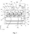
- Figure 1 is a schematic view showing a general structure of a color laser beam printer of a tandem type (hereinafter simply referred to as a printer) in this embodiment.
- the printer includes four image forming engines 10Y, 10M, 10C and 10Bk (indicated by chain lines) for forming toner images of colors of yellow (Y), magenta (M), cyan (C) and black (Bk), respectively.
- the printer further includes an intermediary transfer belt 20 which is a toner image receiving member onto which the toner images are transferred from the engines 10Y, 10M, 10C and 10Bk.
- the toner images transferred superposedly onto the intermediary transfer belt 20 are constituted so that a full-color image is formed on a recording sheet S as a recording material or medium by being transferred onto the recording sheet S.
- symbols Y, M, C and Bk for representing the associated colors will be omitted except for necessary cases.
- the intermediary transfer belt 20 is formed in an endless shape and is extended around a pair of belt feeding rollers 21 and 22, and is constituted so that the toner images formed by the respective image forming engines 10 are transferred onto the intermediary transfer belt 20 while being operated and rotated in an arrow H direction. Further, at a position opposing the belt feeding roller 21 through the intermediary transfer belt 20, a secondary transfer roller 65 is provided.
- the recording sheet S is inserted between the secondary transfer roller 65 and the intermediary transfer belt 20 which are press-contacted to each other, so that the toner images are transferred from the intermediary transfer belt 20 onto the recording sheet S.
- the above-described four image forming engines 10Y, 10M, 10C and 10Bk are disposed in parallel to each other, so that the toner images formed depending on respective pieces of color image information.
- These four image forming engines 10 are disposed along a rotational direction (arrow H direction) of the intermediary transfer belt 20 in the order of the image forming engines 10Y for yellow, 10M for magenta, 10C for cyan and 10Bk for black.
- an optical scanning apparatus 40 for exposing, to light depending on the associated image information, each of photosensitive drums (photosensitive members) 50 which are members-to-be-scanned provided in the respective image forming engines 10 is provided.
- the optical scanning apparatus 40 is common to all of the image forming engines and includes four semiconductor lasers which emit laser beams (light beams) modulated depending on the respective pieces of color image information and which are unshown light sources.
- the optical scanning apparatus 40 includes a rotatable polygonal mirror unit (hereinafter referred to as a deflector) 41 which rotates at high speed and which scans the photosensitive drums 50 in four optical paths with the light beams along rotational axis directions of the photosensitive drums 50 (part (b) of Figure 2 ).
- each of the respective image forming engines 10 includes the photosensitive drum 50 and a charging roller 12 for electrically charging the photosensitive drum 50 to a uniform background portion potential.
- Each of the image forming engines 10 includes a developing device 13 for forming the toner image by developing, with the toner, an electrostatic latent image formed on the photosensitive drum 50 (member-to-be-scanned) by the exposure to the light beam.
- the developing device 13 forms the toner image depending on the associated color image information on the photosensitive drum 50 which is the photosensitive member.
- the developing device 13 is supplied with a developer, in which toner and a carrier are mixed, from a supplying cartridge (not shown).
- a developing type in which a deteriorated developer is automatically discharged is used.
- a primary transfer roller 15 is provided so as to sandwich the intermediary transfer belt 20 between itself and the photosensitive drum 50.
- a predetermined transfer voltage is applied to the primary transfer roller 15, so that the toner image is transferred from the photosensitive drum 50 onto the intermediary transfer belt 20.
- the recording sheet P is supplied from a sheet feeding cassette 2 accommodated at a lower portion of a printer casing 1 to an inside of the printer, specifically a secondary transfer position where the intermediary transfer belt 20 and the secondary transfer roller 65 are in contact with each other.
- a pick-up roller 24 and a sheet feeding roller 25 are provided adjacently to each other.
- a retard roller 26 for preventing double feeding of the recording sheets P is provided at a position opposing the sheet feeding roller 25, a retard roller 26 for preventing double feeding of the recording sheets P is provided.
- a feeding path 27 of the recording sheet P in the printer is provided substantially vertically along a side surface of the printer casing 1.
- the recording sheet P pulled-out from the sheet feeding cassette 2 positioned at the bottom of the printer casing 1 moves upward in the feeding path 27 and is sent to a registration roller pair 29 for controlling an entering timing of the recording sheet P into the secondary transfer position. Thereafter, the recording sheet P is, after the toner image is transferred at the secondary transfer position, sent to a fixing device 3 (indicated by a broken line in Figure 1 ) provided in a downstream side of a recording sheet feeding direction. Then, the recording sheet P on which the toner image is fixed by the fixing device 3 passes through a discharging roller 28 and is discharged onto a discharge tray 1a provided at an upper surface of the printer casing 1.
- the photosensitive drums 50 of the respective image forming engines are exposed to light by the optical scanning apparatus 40.
- a latent image depending on the image information is formed on the associated one of the photosensitive drums 50 of the respective image forming engines 10.
- the latent image formed by the optical scanning apparatus 40 is required to be reproduced at a predetermined position of the photosensitive drum 50 with accuracy. A lowering in image quality generated due to deviation of a laser light condensing position by swing of an optical member in the optical scanning apparatus 40 due to vibration from a driving source is required to be prevented.
- Part (a) of Figure 2 and Figure 4 are schematic perspective views showing the neighborhood of an end portion of a mirror 62 of the optical scanning apparatus 40 in this embodiment.
- Part (b) of Figure 2 is a schematic view showing an arrangement of the optical members inside the optical scanning apparatus of Figure 1 .
- a structure in the casing 105 side will be described while making reference to also parts (a) to (c) of Figure 13 .
- the optical scanning apparatus 40 includes the casing 105, a plurality of light sources (not shown) held at inner and outer peripheral portions of the casing 105, a deflector 41, lenses 64a to 64f, mirrors 62a to 62h, and the like.
- the lenses 64a to 64f are also referred to as the lens(es) 64
- the mirrors 62a to 62h are also referred to as the mirror(s) 62.
- the deflector 41 includes a rotatable polygonal mirror 42.
- the laser light emitted from the light source is constituted so that the laser light is deflected and subjected to scanning by the deflector 41 and passes through the lens 64 and then is reflected by the mirror 62.
- the lens 64 is used for reproducing a predetermined spot diameter on the photosensitive drum 50.
- the mirror 62 is used for guiding the laser light to the photosensitive drum 50.
- the mirror 62 is disposed inside the casing 105 so that a reflecting surface 621 is contaminated and thus a reflectance does not lower.
- the casing 105 includes a bottom on which the rotatable polygonal mirror 42 is mounted and an outer wall portion 105a which is a side wall which stands from the bottom.
- the casing 105 includes supporting bearing surfaces 71 and 72 which are supporting portions for supporting the optical members, and ribs 75 for preventing movement of the optical members in the longitudinal direction so that the optical members do not contact the outer wall portion 105a ( Figure 13 ).
- the casing 105 and the mirror 62 are different in linear expansion coefficient from each other in many cases. For this reason, the mirror 62 is contacted to the supporting bearing surface 71, for holding the mirror 62, which is a part of the casing 105, by an urge force (pressure) of a leaf spring 72, and the mirror 62 is supported and fixed by the supporting bearing surface 71.
- the leaf spring 72 is a member for fixing the optical member to the casing 105.
- the mirror 62 has the reflecting surface 621 including a light beam reflecting region R for reflecting the light beam and a surface 622 opposite from the reflecting surface 621 and contacting the supporting bearing surface 70 described later ( Figure 5 ). Further, the mirror 62 has a surface 623 perpendicular to the reflecting surface 621 and the surface 622 and contacting the supporting bearing surface 71 described later and a surface 624 opposite from the surface 623 ( Figure 5 ).
- the light beam LY which is emitted from the light source (not shown) and which corresponds to the photosensitive drum 50Y is deflected by the rotatable polygonal mirror 42 and enters an optical lens 60a.
- the light beam LY passed through the optical lens 60a enters an optical lens 60b and passes through the optical lens 60b, and thereafter is reflected by the reflecting mirror 62a.
- the light beam LY reflected by the reflecting mirror 62a passes through a transparent window (not shown), so that the photosensitive drum 50Y is scanned with the light beam LY.
- the light beam LM which is emitted from the light source (not shown) and which corresponds to the photosensitive drum 50M is deflected by the rotatable polygonal mirror 42 and enters an optical lens 60a.
- the light beam LM passed through the optical lens 60a enters an optical lens 60b and passes through the optical lens 60b, and thereafter is reflected by the reflecting mirrors 62b, 62c and 62d.
- the light beam LM reflected by the reflecting mirror 62d passes through a transparent window (not shown), so that the photosensitive drum 50M is scanned with the light beam LM.
- the light beam LC which is emitted from the light source (not shown) and which corresponds to the photosensitive drum 50C is deflected by the rotatable polygonal mirror 42 and enters an optical lens 60c.
- the light beam LC passed through the optical lens 60c enters an optical lens 60d and passes through the optical lens 60d, and thereafter is reflected by the reflecting mirrors 62e, 62f and 62g.
- the light beam LC reflected by the reflecting mirror 62g passes through a transparent window (not shown), so that the photosensitive drum 50C is scanned with the light beam LC.
- the light beam LBk which is emitted from the light source (not shown) and which corresponds to the photosensitive drum 50Bk is deflected by the rotatable polygonal mirror 42 and enters an optical lens 60c.
- the light beam LBk passed through the optical lens 60c enters an optical lens 60d and passes through the optical lens 60b, and thereafter is reflected by the reflecting mirror 62h.
- the light beam LBk reflected by the reflecting mirror 62h passes through a transparent window (not shown), so that the photosensitive drum 50Bk is scanned with the light beam LBk.
- the optical lenses 60a to 60d are collectively referred to as the optical lens 60
- the reflecting mirrors 62a to 62h are collectively referred to as the reflecting mirror 62.
- the ribs 75 provided on the casing 105 will be described. Parts (a) to (c) of Figure 3 are schematic views for illustrating a condition in design when the ribs 75 are provided on the casing 105.
- the casing 105 is provided with a rib 75a in one end side of the reflecting mirror 62 and is provided with a rib 75b in the other end side of the reflecting mirror 62.
- the rib 75a is a facing portion facing a side end portion of the reflecting mirror 62 in one end side of the reflecting mirror 62
- the rib 75b is a facing portion facing a side end portion of the reflecting mirror 62 in the other end side of the reflecting mirror 62.
- the ribs 75 are provided in both sides (75a in one end side, 75b in the other end side), but may also have a constitution in which the ribs 75 are provided in one of one end side and the other end side.
- the ribs 75a and 75b are provided for preventing the reflecting mirror 62 from being demounted (detached) from the supporting bearing surfaces 70 (70a, 70b) and the supporting bearing surfaces 71 (71a, 71b) when the reflecting mirror 62 moves in the longitudinal direction.
- the ribs 75a and 75b may also be reinforcing ribs provided for another purpose, for example, for reinforcing the casing 105 (for enhancing rigidity of the casing 105) or may also be side walls of the casing 105.
- a length of the reflecting mirror 62 with respect to the longitudinal direction is L.
- a length of each of the supporting bearing surfaces 70a and 71a which are first mirror supporting portions is W1
- a length of each of the supporting bearing surfaces 70b and 71b which are second mirror supporting portions is W2.
- the lengths W1 and W2 are also a contact width of each of the supporting bearing surfaces 70a and 71a with the reflecting mirror 62 and a contact width of each of the supporting bearing surfaces 70b and 71b with the reflecting mirror 62.
- the supporting bearing surfaces 70a and 71b are also a contact portion thereof with the reflecting mirror 62 with the contact width W1
- the supporting bearing surfaces 70b and 71b are also a contact portion thereof with the reflecting mirror 62 with the contact width W2.
- the supporting bearing surfaces 70a and 71a, the reflecting mirror 62 and the supporting bearing surfaces 70b and 71b constitute bearing surfaces for supporting outermost ends of the reflecting mirror 62 in both sides (one end side, the other end side).
- a distance between the rib 75a and a closest position, to the rib 75a, of the contact portion of the supporting bearing surfaces 70a and 71a with the reflecting mirror 62 is D2.
- a distance between the rib 75b and a closest position, to the rib 75b, of the contact portion of the supporting bearing surfaces 70b and 71b with the reflecting mirror 62 is D3.
- a longest distance among distances between the contact portion of the supporting bearing surfaces 70a and 71a with the reflecting mirror 62 and the contact portion of the supporting bearing surfaces 70b and 71b with the reflecting mirror 62 is D1.
- the ribs 75a and 75b are designed so that a relative positional relationship of the supporting bearing surfaces 70a and 71a with the supporting bearing surfaces 70b and 71b satisfy conditions shown below. Further, the length L of the reflecting mirror 62 is designed so as to satisfy conditions shown below. ⁇ Case of casing on which either one of ribs 75a and 75b exists>
- Part (b) of Figure 3 is a schematic view showing a state the reflecting mirror 62 is shifted to a left side in the figured and is contacted to the rib 75a.
- part (b) of Figure 3 when the side end portion of the reflecting mirror 62 in one end side contacts the rib 75a, there is a need that a design is performed so that the reflecting mirror 62 is not demounted (detached) from the supporting bearing surfaces 70b and 71b in the other end side.
- part (c) of Figure 3 is a schematic view showing a state the reflecting mirror 62 is shifted to a right side in the figured and is contacted to the rib 75b.
- the distance D3 between the rib 75b and the supporting bearing surfaces 70b and 71b satisfies the following formula (2).
- the formula (5) is a condition for permitting the reflecting mirror 62 to enter between the ribs 75a and 75b.
- the length L of the reflecting mirror 62 satisfies both of the following formulas (8) and (9).
- the ribs 75, the supporting bearing surfaces 70 and 71 and the reflecting mirror 62 are designed so as to satisfy the above-described relationships.
- the leaf spring 72 is formed by bonding a single thin plate.
- the leaf spring 72 includes a base portion 72h having a reference surface 72r, first and second plate-like portions 72i and 72j each bent from the base portion 72h, and a pair of a preventing-shaped portions 84.
- the base portion 72h is a portion contacting a spring supporting member 33 which is a leaf spring supporting portion.
- the leaf spring 72 urges (presses) the reflecting mirror 62 in an elastically deformed state in one end side of the reflecting mirror 62 so that the reflecting mirror 62 is urged against the spring supporting member 33.
- the first plate-like portion 72i is folded (bent) from one end of the base portion 72h in a substantially V-shape and extends toward the other end side of the base portion 72h in a side opposite from the reference surface 72r.
- the second plate-like portion 72j is folded (bent) at substantially right angle from the other end of the base portion 72h and extends in a direction crossing the first plate-like portion 72i in a side opposite from a reference surface 72a.
- the pair of preventing-shaped portions 84 which is a pair of preventing members is folded (bent) at substantially right angles from both side ends of the base portion 72h toward the reference surface 72r side (toward a side opposite from the first and second plate-like portions 72i and 72j).
- the reference surface 72r is one surface of the thin plate-like base portion 72h and contacts a prism portion 33a of the spring supporting member 33, and is a basis of a position of the leaf spring 72.
- the first urging portion 72a is a portion bent in a projected shape so as to project toward a side opposite from the base portion 72h at the first plate-like portion 72i.
- the first urging portion 72a contacts the reflecting surface 621 of the mirror 62 by insertion of the first plate-like portion 72i and the base portion 72h between the mirror 62 and the spring supporting portion 72h in a state in which the portions 72i and 72h are flexed (compressed) against an elastic force.
- the first urging portion 72a is elastically urges the mirror 62 against the supporting bearing surface 70 of the mirror supporting member 31.
- the second urging portion 72b is a portion obtained by bending a free end portion of the second plate-like portion 72j in a direction of the first plate-like portion 72i with an obtuse angle.
- the second urging portion 72b contacts a surface 624 of the mirror 62.
- the second urging portion 72b elastically urges the mirror 62 against the supporting bearing surface 71 of the mirror supporting member 31 by locking the leaf spring 72 by the spring supporting member 33 in a flexed (bent) state of the second plate-like portion 72j toward the base portion 72h against the elastic force.
- the hole 72e is an opening provided in the reference surface 72r and penetrates through both sides (surfaces) of the base portion 72h, and a portion defining the hole 75e forms a locking portion (barked portion) 96 engaging with an engaging portion M ( Figure 5 ) of the spring supporting portion 33.
- the base portion 72h includes a portion folded back toward the first plate-like portion 72i, i.e., projected flat surface portions 72m projecting toward both sides at a lower portion of the pair of preventing shaped portions 84, and a free end portion of each of the projected flat surface portions 72m is bent toward a side opposite from the first plate-like portion 72i and constitutes a stopper 72n.
- the stopper 72n is constituted so as to abut against the spring supporting member 33 when the leaf spring 72 is mounted in the casing 105.
- the casing 105 includes the supporting bearing surface 70, at a position corresponding to each of longitudinal end portions of the mirror 62, for holding the surface 622 ( Figure 5 ) which is a longitudinal side surface of the mirror 62 in cross section.
- the supporting bearing surface 70 is constituted as follows so that the leaf spring 72 does not twist the mirror 62 by a force of pressing the mirror 62 in a direction perpendicular to the reflecting surface 621 of the mirror 62 when the supporting bearing surface 70 holds the mirror 62.
- the supporting bearing surface 70 incudes one supporting bearing surface 70a which is a single bearing surface provided at one end portion with respect to the longitudinal direction and includes two supporting bearing surfaces 70b which are two bearing surfaces provided at the other end portion with respect to the longitudinal direction.
- Embodiment 1 a constitution in which the single surface 622 (the longitudinal side surface in cross section) of the mirror 62 is supported by the supporting bearing surfaces 70 (70a, 70b) at three positions (points) in total is employed.
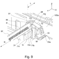
- the casing 105 includes the supporting bearing surfaces 71a and 71b, at positions corresponding to the longitudinal end portions of the mirror 62, for holding the surface 623 ( Figure 5 ) which is a widthwise side surface of the mirror 62 in cross section. Further, as shown in Figure 9 , the casing 105 includes a bearing surface 71c, between the bearing surfaces 71a and 71b, for supporting a surface 623.
- the bearing surface 71c is provided at a position closer to the bearing surface 71b than to the bearing surface 71a.
- a bearing surface (not shown) is provided similarly as in the case of the bearing surface 71c.
- the bearing surface 71c is a bearing surface provided so that the natural frequency of the mirror 62 is a predetermined frequency (estimated frequency in design) in order to prevent the mirror 62 from resonating with vibration of the driving source.
- the leaf spring 72 fixes the mirror 62 to the casing 105 so that the mirror 62 does not move due to the influence of vibration, impact or the like during transportation, an installing operation or the like of the optical scanning apparatus 40.
- the leaf spring 72 includes the first urging portion 72a provided at the free end portion of the first plate-like portion 72i.
- the first urging portion 72a is an urging portion for urging the reflecting surface 621, which is a first surface of the optical member, of the mirror 62 in a direction perpendicular to the reflecting surface 621.
- the leaf spring 72 includes the second urging portion 72b provided at the free end portion of the second plate-like portion 72j.
- the second urging portion 72b is an urging portion for urging the surface 624, which is a second surface perpendicular to the first surface of the optical member, perpendicular to the reflecting surface 621 of the mirror 62.
- the first urging portion 72a urges the reflecting surface 621 of the mirror 62 and thus urges the surface 622, opposite from the reflecting surface 621, against the supporting bearing surface 70.
- the second urging portion 72b urges the surface 624 perpendicular to the reflecting surface 621 and thus urges the surface 623, opposite from the surface 624, against the supporting bearing surface 71.
- the first urging portion 72a and the second urging portion 72b are constituted so as to at least partly overlap with each other with respect to the longitudinal direction of the mirror 62 as seen in an opening direction K of the casing 105 or in a rotational axis direction J of the rotatable polygonal mirror 42 (part (b) of Figure 2 ).
- the opening direction K of the casing 105 and the rotational axis direction J of the rotatable polygonal mirror 42 are the same direction.
- a distance L between a light beam reflection region R of the reflecting surface of the mirror 62 and the outer wall portion 105a of the casing 105 can be designed so as to be small, and therefore the optical scanning apparatus 40 can be downsized.
- the first urging portion 72a of the leaf spring 72 includes a first bent portion 77 at a free end portion thereof.
- the first bent portion 77 is constituted so as to extend from a contact point Q thereof with the reflecting surface 621 of the mirror 62 or the surface 622 opposite from the reflecting surface 621 and so as to become more distant from the mirror 62 with a position toward the opening direction of the casing 105.
- Figure 4 is a schematic view showing a structure of the second urging portion 72b of the leaf spring 72 in Embodiment 1.
- the second urging portion 72b is provided with an opening 78 at a free end portion thereof.
- the opening 78 is provided for guiding an adhesive S, which is an adhesive member, between the leaf spring 72 and the mirror 62.
- the opening 78 is indicated by a broken line and is provided for the purpose of bonding the second urging portion 72b to the surface 624, of the mirror 62, perpendicular to the reflecting surface 621 by being applied dropwisely from above the opening 78 (in an arrow direction).
- Figure 5 is a sectional view of the neighborhood of the leaf spring 72 as seen in the longitudinal direction (-Y direction in Figure 4 ) of the mirror 62 shown in Figure 4 . Incidentally, unrelated shape lines for illustrating Figure 5 are removed.
- the adhesive S is applied dropwisely from above the opening 78.
- Figure 5 shows a state after a lapse of a certain time from the drop
- the adhesive S changes in shape due to viscosity in a period from the dropwise application to solidification thereof.
- the adhesive S entering the opening 78 contacts both of the second urging portion 72b and the mirror 62.
- the adhesive S which does not enter the opening 78 runs while moving in a direction of gravitation.
- the second urging portion 72b is provided with a receiving and throttling portion 79 which is a recess-shaped portion.
- the receiving and throttling portion 79 is formed at the second urging portion 72 as the recess-shaped portion recessed toward the first urging portion 72a side (toward the mirror 62 side).
- the opening 78 is provided.
- the adhesive S moved in the direction of gravitation is held by the receiving and throttling portion 79.
- a moving speed and a moving distance of the adhesive S depend on a viscosity of the adhesive S before curing. Even after a lapse of a certain time, the adhesive S does not readily move in the direction of gravitation when the viscosity is high, and a movement amount of the adhesive S is large when the viscosity is low.
- an ultraviolet (UV) curable adhesive is assumed.
- the viscosity before curing with ultraviolet rays various values thereof are prepared. For this reason, an adhesive having an adhesive and a viscosity such that the adhesive can be held by the shape of the receiving and throttling portion 79 may only be required to be selected.
- Figure 6 is an enlarged view of a shape at a periphery of the adhesive S shown in Figure 5 .
- the second urging portion 72b includes the opening 78 and the receiving and throttling portion 79 provided around the opening 78.
- an edge 81 which is an edge portion of the receiving and throttling portion 79 defining the opening 78 has a shape such that the edge 81 cannot directly contact the mirror 62.
- the edge 81 has a shape such that the edge 81 is directly contactable to the mirror 71, when the leaf spring 72 is mounted to the casing 105, there is a possibility that a change in attitude of the mirror 62 is caused by a force exerted on the mirror 62.
- the shape of the receiving and throttling portion 79 is formed so that the receiving and throttling portion 79 is warped toward the opening 78, and constitutes a return shape portion 82.
- the receiving and throttling portion 79 of the leaf spring 72 includes the return shape portion 82.
- the receiving and throttling portion 79 of the leaf spring 72 is seen in a cross section perpendicular to the longitudinal direction of the mirror 62, the receiving and throttling portion 79 has a projected shape such that the receiving and throttling portion 79 projects toward the mirror 62 side at two points 80 and 90.
- the point 80 contacts the mirror 62 but the point 90 does not contact the mirror 62.
- the receiving and throttling portion 79 of the leaf spring 72 always contacts the mirror 62 in a downstream side of the direction of gravitation.
- the point 90 disposed in an upstream side opposite from the downstream side in the direction of gravitation does not contact the mirror 62.
- the portion, in the neighborhood of the opening 78, of the second urging portion 72b of the leaf spring 72 is formed as the return shape portion 82, so that a region in which the leaf spring 72 contacts the mirror 62 in the neighborhood of the opening 78 contacts the mirror 62 in a line-contact manner or a point-contact manner along a circumference of the opening 78, not in a plane (surface)-contact manner.
- the contact of the second urging portion 72b with the mirror 62 at an entirety of the circumference of the opening 78 is not practical when a component tolerance is taken into consideration. Therefore, the mirror 62 and the second urging portion 72 are ought to contact each other in the point-contact manner or in a region close to a point-contact region. At that time, a priority is such that the adhesive S entering the opening 78 does not flow in the direction of gravitation.
- the adhesive S enters the opening 78, when a constitution in which the second urging portion 72b of the leaf spring 72 always point-contacts the mirror 62 at the point 80 (or partly line-contacts the mirror 62 along the circumference of the opening 78) is employed, the adhesive S can be held at the contact portion.
- Figure 7 is a perspective view of a region including the point 80 as seen from a back side without illustrating the casing 105.
- the point 80 has a shape slightly extending along the circumference of the opening 78.
- the adhesive S contacts the mirror 62 in a self-weight flowing side, i.e., the downstream side of the direction of gravitation.
- the adhesive S which is the UV curable adhesive S is cured.
- the mirror 62 and the second urging portion 72b are firmly fixed to each other with the adhesive S.
- Figure 8 is a graph showing data by which whether or not the natural frequency of the mirror 62 is changed by bonding the mirror 62 and the leaf spring 72 to each other with the adhesive S was checked.
- the abscissa represents a frequency (Hz), and the ordinate represents an acceleration (m/s 2 ).
- "SIDE FREE" indicated by a solid line is a graph measured in a state such that the bonding with the adhesive S is not carried out and the longitudinal end portions of the mirror 62 are not contacted to the casing 105 (rib 75).
- SIDE CONTACT indicated by a broken line is a graph measured in a state such that the bonding with the adhesive S is not carried out and the longitudinal end portions of the mirror 62 are contacted to the casing 105 (rib 75). It is understood that the natural frequency of the mirror 62 changes depending on whether or not the mirror 62 contacts the casing 105 (rib 75).
- the reflecting mirror 62 is fixed by the first leaf spring 72 in one end side and is fixed by the second leaf spring 72 in the other end side. At least one of the first leaf spring 72 and the second leaf spring 72 is bonded to the reflecting mirror 62 with the adhesive S.
- the case where only the first leaf spring 72 for fixing the reflecting mirror 62 in one end side is bonded and the case where only the second leaf spring 72 for fixing the reflecting mirror 62 in the other end side is bonded exist. Further, there is a case where both of the first leaf spring 72 for fixing the reflecting mirror 62 in one end side and the second leaf spring 72 for fixing the reflecting mirror 72 in the other end side are bonded.
- “BOTH SIDE BONDING” indicated by a chain double-dashed line is a graph measured in a state in which the bond with the adhesive S is carried out using the leaf spring 72 in this embodiment and the longitudinal end portions of the mirror 62 is not contacted to the casing 105 (rib 75).
- the mirror 62 and the leaf spring 72 are bonded to each other with the adhesive S.
- a constitution in which the supporting bearing surfaces 70, provided at the longitudinal end portions, for holding the surface 622 which is a longitudinal side surface of the mirror 62 in cross section includes the single supporting bearing surface 70a in one end side and the two supporting bearing surfaces 70b in the other end side and thus the single surface 622 is supported by the three bearing surfaces in total.
- the reason why the surface 622 is supported by the three bearing surfaces is that when the mirror 62 is held by the bearing surfaces 70, the mirror 62 is prevented from twisting caused by a force of the leaf spring 72 pressing the mirror 62 in the direction perpendicular to the reflecting surface 621 of the mirror 62.
- the bearing surfaces from which the mirror 62 is liable to demount (detach) due to an impact or the like exerted on the optical scanning apparatus 40 during transportation are the supporting bearing surfaces 70 in the two-point side close to the end portion of the mirror 62.
- a constitution in which the leaf spring 72 for fixing the mirror 62 to the supporting bearing surfaces 70b in the two-point supporting side is bonded to the mirror 62 and holds (supports) the mirror 62 is excellent in shock (impact) resistance.
- a constitution in which the leaf spring 72 is provided with a pair of preventing shape portions 84 (back surface thereof is not shown) may also be employed.
- a constitution in which the spring supporting member 33 of the casing 105 is provided with the prism portion 33a and the preventing shape portions 84 of the leaf spring 72 elastically sandwiches the prism portion 33 may only be required to be employed.
- the natural frequency of the elongated reflecting mirror provided in the optical scanning apparatus can be stabilized with a simple constitution.
- the mirror 62 is bonded and the longitudinal position of the mirror 62 is regulated.
- stabilization of the natural frequency of the mirror 62 is realized.
- the regulation of the longitudinal position of the mirror 62 is carried out by bonding the mirror 62 to the elastic member for fixing the mirror 62, the present invention is not limited to the above-described embodiment.
- the adhesive S is applied using the gap between the optical member (member 62) and the outer wall portion 105a and therefore an increase in size of the casing 105 can be avoided.
- the second urging portion 72b is provided with the opening 78, so that when the adhesive S is applied from above the opening 78, the adhesive S spreads all over both of the optical member and the opening 78 and thus the bonding can be easily carried out.
- the receiving and throttling portion 79 having the projected shape is provided in a lower side where the adhesive member can be held, so that when the adhesive S is applied, flowing-out of the adhesive S in an uncured state toward the light beam reflecting region R side of the mirror 62 can be avoided. For this reason, operativity during the bonding step can be improved.
- the edge 81 of the opening 78 has a shape such that the edge 81 does not directly contact the surface 624 of the mirror 62. As a result, it is possible to avoid the change in attitude of the mirror 62 caused by the edge 81 of the opening 78.
- the region where the leaf spring 72 contacts the surface 624 of the mirror 62 is always the downstream side of the direction of gravitation. Therefore, the flowing-out, toward the light beam reflecting region R side of the mirror 62, of the adhesive S which entered the opening 78 and which is in the uncured state can be avoided. For this reason, the operativity during the bonding step can be improved.
- the bonding between the leaf spring 72 and the mirror 62 may be carried out in the one-point supporting bearing surface side or the two-point supporting bearing surface side.
- the mirror 62 may also be bonded at both end portions thereof.
- the mirror 62 is bonded in the bearing surface side where the mirror 62 is supported by the two points, so that when the impact (shock) is applied, demounting of the mirror surface from the two-point supporting surfaces can be avoided and thus reliability is improved.
- Embodiment 1 the constitution in which the second urging portion 72b of the leaf spring 72 is bonded to the mirror 62 is employed.
- a constitution in which the first urging portion 72a of the leaf spring 72 is bonded to the mirror 62 will be described.
- constitutions of the printer and the optical scanning apparatus 40 are similar to those in Embodiment 1 and are represented by the same reference numerals or symbols, and will be omitted from description.
- the leaf spring 72 in this embodiment has a constitution for bonding the adhesive S to the first urging portion 72a.
- the first urging portion 72a includes a first bent portion 77 bent toward the second plate-like portion 72j at a free end portion thereof and a pair of second bent portions 89 each extending from the first bent portion 77 toward the second urging portion 72b side.
- the pair of second bent portions 89 is bent from both ends of the first bent portion 77 toward the second urging portion 72b side at substantially right angles.
- the leaf spring 72 is constituted so that at least a part of the first bent portion 77 provided at the first urging portion n72a overlaps with at least a part of the second urging portion 72b as seen in an arrow K direction or an arrow J direction in part (b) of Figure 2 .
- a first opening 88 for permitting application of the adhesive S onto the first bent portion 77 is provided at a part of the second plate-like portion 72j of the leaf spring 72.
- the adhesive S is applied onto the first urging portion 72a through the first opening 88 provided in the second plate-like portion 72j of the leaf spring 72. Movement of the adhesive S in the longitudinal direction of the mirror 62 is prevented by the second bent portions 89.
- the adhesive S can be smoothly applied onto a contact point between the mirror 62 and the leaf spring 72 provided in a space-saving manner. That is, the adhesive S accesses the mirror 62 from the light beam reflecting region R side, so that positioning of the mirror 62 and stabilization of the natural frequency of the mirror 62 can be realized without contaminating the reflecting surface 621 of the mirror 62. Further, it becomes possible to realize the positioning of the mirror 62 and the stabilization of the natural frequency of the mirror 62 while avoiding such a problem that a size of the casing 105 is required to be increased for applying the adhesive S by using the gap between the leaf spring 72 and a wall surface of the outer wall portion 105a of the casing 105.
- the leaf spring 72 includes the first bent portion 77, so that the adhesive S can be applied between the mirror 62 and the first bent portion 77 and thus the operation is facilitated.
- Parts (a) and (b) of Figure 11 are schematic perspective views for illustrating a state in which the mirror 62 is fixed by the leaf spring 72 at one end portion of the mirror 62 in this embodiment.
- Parts (c) and (d) of Figure 11 are perspective views showing a structure of the leaf spring 72 in this embodiment.
- the leaf spring 72 includes the first bent portion 77 in the neighborhood of a contact point Q ( Figure 9 ) with the mirror 62 and the pair of second bent portions 89 at both end portions of the first bent portion 77 with respect to the longitudinal direction of the mirror 62.
- a second opening 74 for permitting flow of the adhesive S toward a rotation center during deformation of the first urging portion 72a of the leaf spring 72 in the case where an amount of the applied adhesive S is excessively large.
- Figure 12 is a graph showing data by which whether or not the natural frequency of the mirror 62 is changed by bonding the mirror 62 and the first urging portion 72a of the leaf spring 72 to each other with the adhesive S was checked.
- the graphs in Figure 12 are similar to those in Figure 8 , and therefore, will be omitted from description.
- the natural frequency is unchanged from the case of "SIDE FREE".
- the position of the mirror 62 can be prevented from deviating, by the fixing to the mirror 62 with use of the leaf spring 72 and thus by bonding the leaf spring 72 and the mirror 62 to each other, without shifting the natural frequency (resonance point) of the mirror 62.
- the natural frequency of the elongated reflecting mirror installed in the optical scanning apparatus can be stabilized with a simple constitution.
- the natural frequency of the elongated reflecting mirror provided in the optical scanning apparatus can be stabilized with the simple constitution.
- An optical scanning apparatus includes a light source, a deflecting unit, a reflection mirror, a casing, and first and second leaf springs.
- the casing includes first and second mirror supporting portions and a facing portion. The following relationship is satisfied: D2 ⁇ L + W - D1. With respect to a longitudinal direction, L is a length of the reflection mirror, D1 is a longest distance between the first and second supporting portions, W is a contact width of the second supporting portion to the reflection mirror, and D2 is a distance between the facing portion and a closest position thereto of the first supporting portion.
- the first and second leaf springs urge the reflection mirror against the first and second mirror supporting portions, respectively. At least one of the first and second leaf springs is bonded to the reflection mirror with an adhesive.
Landscapes
- Physics & Mathematics (AREA)
- General Physics & Mathematics (AREA)
- Optics & Photonics (AREA)
- Engineering & Computer Science (AREA)
- Multimedia (AREA)
- Signal Processing (AREA)
- Mechanical Optical Scanning Systems (AREA)
- Laser Beam Printer (AREA)
- Facsimile Scanning Arrangements (AREA)
- Exposure Or Original Feeding In Electrophotography (AREA)
Abstract
Description
- The present invention relates to an optical scanning apparatus for use with an image forming apparatus such as a copying machine, a printer, a facsimile machine or a multi-function machine having functions of these machines, and relates to the image forming apparatus including the optical scanning apparatus.
- In the image forming apparatus, a rotatable polygonal mirror provided in the optical scanning apparatus is rotated and a direction of laser light is changed while scanning a photosensitive member with the laser light, so that a latent image is formed on the photosensitive member. In order to save an installation space and a cost of the mirror, the mirror is designed so that the mirror has an elongated shape and a small size to the extent possible.
- The mirror is urged and supported by a mirror supporting portion provided in a casing of the optical scanning apparatus and is fixed to the casing. In general, as shown in part (a) of
Figure 13 , mirror supportingbearing surfaces mirror 62 with respect to a longitudinal direction of the mirror. An elastic member 172 (part (c) ofFigure 13 ) employs a constitution such that theelastic member 172 is mounted at a position opposing the supportingbearing surfaces mirror 62 and urges themirror 62 toward the supportingbearing surfaces 70 and 71 (part (b) ofFigure 13 ). However, in such a constitution employed in general, there is a liability that themirror 62 vibrates. In the image forming apparatus, in addition to the optical scanning apparatus, movable portions such as a sheet feeding roller, the photosensitive member, an intermediary transfer member, a fixing belt or roller, and the like and a driving system for driving these members are provided. When the driving system for these members is operated, vibration generating from the driving system is transmitted to the optical scanning apparatus, and thus there is a liability that themirror 62 vibrates. When themirror 62 vibrates, with the vibration of themirror 62, a direction of reflected light of the laser light is changed. For that reason, an imaging (image forming) position of the laser light on the photosensitive member deviates from a desired position. As a result, non-uniformity such as a striped pattern generates on an image to be outputted. - In order to solve this problem, Japanese Laid-Open Patent Application
2001-215434 - However, there is a liability that the natural frequency of the mirror is changed after shipping of a product. The casing of the optical scanning apparatus is provided with abutting portions outside both ends of the
mirror 62 with respect to the longitudinal direction of themirror 62. For example, the casing of the optical scanning apparatus shown inFigure 13 is provided withribs 75 at both ends thereof. Each of theribs 75 functions as a stopper for preventing themirror 62 from disconnecting from the supporting bearing surface by movement of themirror 62 due to transportation of the product during shipping or vibration of the production during installation. However, there is a liability that a value of the natural frequency of themirror 62 is changed by contact of themirror 62 to therib 75 by movement of themirror 62 in the longitudinal direction. As a result, there is a liability that the natural frequency unintentionally coincides with the frequency of the plurality of the driving systems, and thus not only the mirror largely vibrates but also image deterioration generates. Incidentally, a product such that a side wall of the casing of the optical scanning apparatus functions as a stopper also exists. -
Figure 14 is a graph showing a frequency (Hz) in the abscissa and acceleration (m/s2) at central portion of the mirror with respect to the longitudinal direction in the ordinate. InFigure 14 , the graph in which the acceleration at the central portion of the member is measured while changing the frequency when anend portion 62t of themirror 62 contacts therib 75 of the casing is indicate by a broken line ("SIDE CONTACT"). InFigure 14 , the graph in which the acceleration at the central portion of the mirror is measured while changing the frequency when theend portion 62t of themirror 62 does not contact therib 75 of the casing is indicated by a solid line ("SIDE FREE"). As shown inFigure 14 , it is understood that the natural frequency is changed by 100 Hz or more due to a small difference between the case where theend portion 62t of themirror 62 contacts therib 75 of the casing and the case where theend portion 62t of themirror 62 does not contact therib 75 of the casing. In the case where in a vibration mode of the driving system of an image forming apparatus main assembly, there is a peak in the neighborhood of 450 Hz, there is a liability that by the contact of themirror 62 to therib 75, the mirror 6 resonates with the vibration of the image forming apparatus main assembly. - The present invention has been accomplished in the above-described circumstances, and a principal object of the present invention is to provide an optical scanning apparatus and an image forming apparatus, in which a natural frequency of an elongated reflecting mirror mounted in the optical scanning apparatus is stabilized by a simple constitution.
- According to an aspect of the present invention, there is provided an optical scanning apparatus comprising: a light source configured to emit a light beam; a deflecting unit configured to deflect the light beam so that a photosensitive member is scanned with the light beam emitted from the light source; a reflection mirror configured to guide the light beam, onto the photosensitive member, deflected by the deflecting unit; and a casing configured to accommodate the deflecting unit and the reflection mirror; and first and second leaf springs, wherein the casing includes a first mirror supporting portion configured to support the reflection mirror in one end side, a second mirror supporting portion configured to support the reflection mirror in the other end side with respect to a longitudinal direction of the reflection mirror, and a facing portion configured to face a side end portion of the reflection mirror in said one end side, wherein the following relationship is satisfied:

- According to another aspect of the present invention, there is provided an optical scanning apparatus comprising: a light source configured to emit a light beam; a deflecting unit configured to deflect the light beam so that a photosensitive member is scanned with the light beam emitted from the light source; a reflection mirror configured to guide the light beam, onto the photosensitive member, deflected by the deflecting unit; and a casing configured to accommodate the deflecting unit and the reflection mirror; and first and second leaf springs, wherein the casing includes a first mirror supporting portion configured to support the reflection mirror in one end side, a second mirror supporting portion configured to support the reflection mirror in the other end side with respect to a longitudinal direction of the reflection mirror, a first facing portion configured to face a side end portion of the reflection mirror in said one end side, and a roller facing portion configured to face a side end portion of the reflecting mirror in said the other end side, wherein the following relationships are satisfied:


- According to a further aspect of the present invention, there is provided an image forming apparatus comprising: a photosensitive member, one of the above-described two optical scanning apparatuses configured to form a latent image on the photosensitive member; a developing portion (unit) configured to develop, with toner, the latent image formed by the optical scanning apparatus thereby to form a toner image; and a transfer portion (unit) configured to transfer the toner image, formed by the developing portion, onto a toner image receiving member.
- Further features of the present invention will become apparent from the following description of exemplary embodiments with reference to the attached drawings.
-
-
Figure 1 is a schematic view showing a structure of an image forming apparatus inEmbodiments - Parts (a) and (b) of
Figure 2 are schematic views showing an end portion of a mirror inEmbodiment 1, and an arrangement of optical members and an optical path of laser light inEmbodiments - Parts (a), (b) and (c) of
Figure 3 are schematic views each for illustrating a relationship among a member, supporting bearing surfaces and ribs inEmbodiment 1. -
Figure 4 is a schematic view for illustrating a bonding method between the mirror and an elastic member inEmbodiment 1. -
Figure 5 is a sectional view for illustrating the bonding method between the mirror and the elastic member inEmbodiment 1. -
Figure 6 is an enlarged view of a second urging portion of the elastic member in Embodiment 1. -
Figure 7 is a schematic view of the mirror and the elastic member inEmbodiment 1 as seen from a back side. -
Figure 8 is a graph for checking a change in natural frequency inEmbodiment 1. -
Figure 9 is a schematic view showing an end portion of a mirror inEmbodiment 2. -
Figure 10 is a schematic view for illustrating the mirror and an elastic member inEmbodiment 2. - Parts (a) to (d) of
Figure 11 are schematic views each showing a constitution of the elastic member inEmbodiment 2. -
Figure 12 is a graph for checking a change in natural frequency inEmbodiment 1. - Parts (a), (b) and (c) of
Figure 13 are schematic views for illustrating a supporting bearing surface of a mirror in a conventional example. -
Figure 14 is a graph showing a change in natural frequency during side free and during side contact in the conventional example. - Embodiments for carrying out the present invention will be specifically described with reference to the drawings. In the following description, a rotational axis direction of a rotatable polygonal mirror is Z-axis direction, a main scan direction as a scanning direction of a light beam or a longitudinal direction of a mirror is Y-axis direction, and a direction perpendicular to the Y-axis direction and the Z-axis direction is X-axis direction.
- A structure (constitution) of an image forming apparatus in
Embodiment 1 will be described.Figure 1 is a schematic view showing a general structure of a color laser beam printer of a tandem type (hereinafter simply referred to as a printer) in this embodiment. The printer includes fourimage forming engines intermediary transfer belt 20 which is a toner image receiving member onto which the toner images are transferred from theengines intermediary transfer belt 20 are constituted so that a full-color image is formed on a recording sheet S as a recording material or medium by being transferred onto the recording sheet S. In the following, symbols Y, M, C and Bk for representing the associated colors will be omitted except for necessary cases. - The
intermediary transfer belt 20 is formed in an endless shape and is extended around a pair ofbelt feeding rollers intermediary transfer belt 20 while being operated and rotated in an arrow H direction. Further, at a position opposing thebelt feeding roller 21 through theintermediary transfer belt 20, asecondary transfer roller 65 is provided. - The recording sheet S is inserted between the
secondary transfer roller 65 and theintermediary transfer belt 20 which are press-contacted to each other, so that the toner images are transferred from theintermediary transfer belt 20 onto the recording sheet S. In a lower side of theintermediary transfer belt 20, the above-described fourimage forming engines intermediary transfer belt 20 in the order of theimage forming engines 10Y for yellow, 10M for magenta, 10C for cyan and 10Bk for black. - Below the image forming engines 10, an
optical scanning apparatus 40 for exposing, to light depending on the associated image information, each of photosensitive drums (photosensitive members) 50 which are members-to-be-scanned provided in the respective image forming engines 10 is provided. Theoptical scanning apparatus 40 is common to all of the image forming engines and includes four semiconductor lasers which emit laser beams (light beams) modulated depending on the respective pieces of color image information and which are unshown light sources. Theoptical scanning apparatus 40 includes a rotatable polygonal mirror unit (hereinafter referred to as a deflector) 41 which rotates at high speed and which scans the photosensitive drums 50 in four optical paths with the light beams along rotational axis directions of the photosensitive drums 50 (part (b) ofFigure 2 ). The respective light beams with which the photosensitive drums 50 are scanned by the deflector 41 and advance along predetermined paths while being guided by optical members provided in theoptical scanning apparatus 40. Then, the respective photosensitive drums 50 of the image forming engines 10 are exposed to the light beams through irradiation openings (not shown) provided at an upper portion of theoptical scanning apparatus 40. - Further, each of the respective image forming engines 10 includes the photosensitive drum 50 and a charging roller 12 for electrically charging the photosensitive drum 50 to a uniform background portion potential. Each of the image forming engines 10 includes a developing
device 13 for forming the toner image by developing, with the toner, an electrostatic latent image formed on the photosensitive drum 50 (member-to-be-scanned) by the exposure to the light beam. The developingdevice 13 forms the toner image depending on the associated color image information on the photosensitive drum 50 which is the photosensitive member. In order to omit maintenance for replacing the developer with a change with time, the developingdevice 13 is supplied with a developer, in which toner and a carrier are mixed, from a supplying cartridge (not shown). As regards the developingdevice 13, a developing type in which a deteriorated developer is automatically discharged is used. - At a position opposing the photosensitive drum 50 of the associated one of the image forming engines 10, a primary transfer roller 15 is provided so as to sandwich the
intermediary transfer belt 20 between itself and the photosensitive drum 50. A predetermined transfer voltage is applied to the primary transfer roller 15, so that the toner image is transferred from the photosensitive drum 50 onto theintermediary transfer belt 20. - On the other hand, the recording sheet P is supplied from a
sheet feeding cassette 2 accommodated at a lower portion of aprinter casing 1 to an inside of the printer, specifically a secondary transfer position where theintermediary transfer belt 20 and thesecondary transfer roller 65 are in contact with each other. At an upper portion of thesheet feeding cassette 2, a pick-uproller 24 and asheet feeding roller 25 are provided adjacently to each other. Further, at a position opposing thesheet feeding roller 25, aretard roller 26 for preventing double feeding of the recording sheets P is provided. A feedingpath 27 of the recording sheet P in the printer is provided substantially vertically along a side surface of theprinter casing 1. The recording sheet P pulled-out from thesheet feeding cassette 2 positioned at the bottom of theprinter casing 1 moves upward in thefeeding path 27 and is sent to aregistration roller pair 29 for controlling an entering timing of the recording sheet P into the secondary transfer position. Thereafter, the recording sheet P is, after the toner image is transferred at the secondary transfer position, sent to a fixing device 3 (indicated by a broken line inFigure 1 ) provided in a downstream side of a recording sheet feeding direction. Then, the recording sheet P on which the toner image is fixed by the fixingdevice 3 passes through a dischargingroller 28 and is discharged onto adischarge tray 1a provided at an upper surface of theprinter casing 1. - For full-color image formation by the thus-constituted color laser beam printer, first, depending on pieces of image information of the respective colors, the photosensitive drums 50 of the respective image forming engines are exposed to light by the
optical scanning apparatus 40. As a result, a latent image depending on the image information is formed on the associated one of the photosensitive drums 50 of the respective image forming engines 10. In order to obtain a good image quality, the latent image formed by theoptical scanning apparatus 40 is required to be reproduced at a predetermined position of the photosensitive drum 50 with accuracy. A lowering in image quality generated due to deviation of a laser light condensing position by swing of an optical member in theoptical scanning apparatus 40 due to vibration from a driving source is required to be prevented. Therefore, with respect to driving frequencies of various driving sources in the image forming apparatus, natural frequencies of all of optical members are required to be not coincident with the driving frequencies. For that reason, in a state in which the optical members are supported by acasing 105, it is required that attitudes of the optical members are stabilized so that the natural frequencies of the optical members do not largely change. - Part (a) of
Figure 2 andFigure 4 are schematic perspective views showing the neighborhood of an end portion of amirror 62 of theoptical scanning apparatus 40 in this embodiment. Part (b) ofFigure 2 is a schematic view showing an arrangement of the optical members inside the optical scanning apparatus ofFigure 1 . A structure in thecasing 105 side will be described while making reference to also parts (a) to (c) ofFigure 13 . Theoptical scanning apparatus 40 includes thecasing 105, a plurality of light sources (not shown) held at inner and outer peripheral portions of thecasing 105, a deflector 41, lenses 64a to 64f, mirrors 62a to 62h, and the like. In the following, the lenses 64a to 64f are also referred to as the lens(es) 64, and themirrors 62a to 62h are also referred to as the mirror(s) 62. The deflector 41 includes a rotatablepolygonal mirror 42. The laser light emitted from the light source is constituted so that the laser light is deflected and subjected to scanning by the deflector 41 and passes through the lens 64 and then is reflected by themirror 62. The lens 64 is used for reproducing a predetermined spot diameter on the photosensitive drum 50. Themirror 62 is used for guiding the laser light to the photosensitive drum 50. Themirror 62 is disposed inside thecasing 105 so that a reflectingsurface 621 is contaminated and thus a reflectance does not lower. Thecasing 105 includes a bottom on which the rotatablepolygonal mirror 42 is mounted and anouter wall portion 105a which is a side wall which stands from the bottom. Thecasing 105 includes supporting bearing surfaces 71 and 72 which are supporting portions for supporting the optical members, andribs 75 for preventing movement of the optical members in the longitudinal direction so that the optical members do not contact theouter wall portion 105a (Figure 13 ). - The
casing 105 and themirror 62 are different in linear expansion coefficient from each other in many cases. For this reason, themirror 62 is contacted to the supportingbearing surface 71, for holding themirror 62, which is a part of thecasing 105, by an urge force (pressure) of aleaf spring 72, and themirror 62 is supported and fixed by the supportingbearing surface 71. Theleaf spring 72 is a member for fixing the optical member to thecasing 105. - The
mirror 62 has the reflectingsurface 621 including a light beam reflecting region R for reflecting the light beam and asurface 622 opposite from the reflectingsurface 621 and contacting the supportingbearing surface 70 described later (Figure 5 ). Further, themirror 62 has asurface 623 perpendicular to the reflectingsurface 621 and thesurface 622 and contacting the supportingbearing surface 71 described later and asurface 624 opposite from the surface 623 (Figure 5 ). - Next, using part (b) of
Figure 2 , optical paths of light beams LBk, LC, LM and LY will be described. The light beam LY which is emitted from the light source (not shown) and which corresponds to thephotosensitive drum 50Y is deflected by the rotatablepolygonal mirror 42 and enters anoptical lens 60a. The light beam LY passed through theoptical lens 60a enters anoptical lens 60b and passes through theoptical lens 60b, and thereafter is reflected by the reflectingmirror 62a. The light beam LY reflected by the reflectingmirror 62a passes through a transparent window (not shown), so that thephotosensitive drum 50Y is scanned with the light beam LY. - The light beam LM which is emitted from the light source (not shown) and which corresponds to the
photosensitive drum 50M is deflected by the rotatablepolygonal mirror 42 and enters anoptical lens 60a. The light beam LM passed through theoptical lens 60a enters anoptical lens 60b and passes through theoptical lens 60b, and thereafter is reflected by the reflectingmirrors mirror 62d passes through a transparent window (not shown), so that thephotosensitive drum 50M is scanned with the light beam LM. - The light beam LC which is emitted from the light source (not shown) and which corresponds to the
photosensitive drum 50C is deflected by the rotatablepolygonal mirror 42 and enters anoptical lens 60c. The light beam LC passed through theoptical lens 60c enters anoptical lens 60d and passes through theoptical lens 60d, and thereafter is reflected by the reflectingmirrors mirror 62g passes through a transparent window (not shown), so that thephotosensitive drum 50C is scanned with the light beam LC. - The light beam LBk which is emitted from the light source (not shown) and which corresponds to the photosensitive drum 50Bk is deflected by the rotatable
polygonal mirror 42 and enters anoptical lens 60c. The light beam LBk passed through theoptical lens 60c enters anoptical lens 60d and passes through theoptical lens 60b, and thereafter is reflected by the reflectingmirror 62h. The light beam LBk reflected by the reflectingmirror 62h passes through a transparent window (not shown), so that the photosensitive drum 50Bk is scanned with the light beam LBk. In the following description, theoptical lenses 60a to 60d are collectively referred to as the optical lens 60, and the reflectingmirrors 62a to 62h are collectively referred to as the reflectingmirror 62. - The
ribs 75 provided on thecasing 105 will be described. Parts (a) to (c) ofFigure 3 are schematic views for illustrating a condition in design when theribs 75 are provided on thecasing 105. Thecasing 105 is provided with arib 75a in one end side of the reflectingmirror 62 and is provided with arib 75b in the other end side of the reflectingmirror 62. Therib 75a is a facing portion facing a side end portion of the reflectingmirror 62 in one end side of the reflectingmirror 62, and therib 75b is a facing portion facing a side end portion of the reflectingmirror 62 in the other end side of the reflectingmirror 62. InFigure 3 , the ribs 75 (75a, 75b) are provided in both sides (75a in one end side, 75b in the other end side), but may also have a constitution in which theribs 75 are provided in one of one end side and the other end side. - The
ribs mirror 62 from being demounted (detached) from the supporting bearing surfaces 70 (70a, 70b) and the supporting bearing surfaces 71 (71a, 71b) when the reflectingmirror 62 moves in the longitudinal direction. Incidentally, theribs casing 105. - Here, as shown in part (a) of
Figure 3 , a length of the reflectingmirror 62 with respect to the longitudinal direction is L. A length of each of the supportingbearing surfaces bearing surfaces mirror 62 and a contact width of each of the supporting bearing surfaces 70b and 71b with the reflectingmirror 62. The supportingbearing surfaces mirror 62 with the contact width W1, and the supporting bearing surfaces 70b and 71b are also a contact portion thereof with the reflectingmirror 62 with the contact width W2. With respect to the longitudinal direction of the reflectingmirror 62, the supportingbearing surfaces mirror 62 and the supporting bearing surfaces 70b and 71b constitute bearing surfaces for supporting outermost ends of the reflectingmirror 62 in both sides (one end side, the other end side). - A distance between the
rib 75a and a closest position, to therib 75a, of the contact portion of the supportingbearing surfaces mirror 62 is D2. A distance between therib 75b and a closest position, to therib 75b, of the contact portion of the supporting bearing surfaces 70b and 71b with the reflectingmirror 62 is D3. A longest distance among distances between the contact portion of the supportingbearing surfaces mirror 62 and the contact portion of the supporting bearing surfaces 70b and 71b with the reflectingmirror 62 is D1. - The
ribs bearing surfaces mirror 62 is designed so as to satisfy conditions shown below. <Case of casing on which either one ofribs - Part (b) of
Figure 3 is a schematic view showing a state the reflectingmirror 62 is shifted to a left side in the figured and is contacted to therib 75a. As shown in part (b) ofFigure 3 , when the side end portion of the reflectingmirror 62 in one end side contacts therib 75a, there is a need that a design is performed so that the reflectingmirror 62 is not demounted (detached) from the supporting bearing surfaces 70b and 71b in the other end side. Further, part (c) ofFigure 3 is a schematic view showing a state the reflectingmirror 62 is shifted to a right side in the figured and is contacted to therib 75b. As shown in part (c) ofFigure 3 , when the side end portion of the reflectingmirror 62 in the other end side contacts therib 75b, there is a need that a design is performed so that the reflectingmirror 62 is not demounted (detached) from the supportingbearing surfaces casing 105 on which either one of theribs rib 75a and the supportingbearing surfaces 
- Alternatively, the distance D3 between the
rib 75b and the supporting bearing surfaces 70b and 71b satisfies the following formula (2).
- In the case of the
casing 105 on which both of theribs 


- Here, the formula (5) is a condition for permitting the reflecting
mirror 62 to enter between theribs - Accordingly, in the case of the
casing 105 on which both of theribs - The distance D2 between the
rib 75a and the supportingbearing surfaces 
- The distance D3 between the
rib 75b and the supporting bearing surfaces 70b and 71b satisfies the following formula (7).
- The length L of the reflecting
mirror 62 satisfies both of the following formulas (8) and (9).

- The
ribs 75, the supporting bearing surfaces 70 and 71 and the reflectingmirror 62 are designed so as to satisfy the above-described relationships. - With reference to
Figures 2 to 7 and13 , a structure of theleaf spring 72 and a structure of thecasing 105 in the neighborhood of a position where themirror 62 is mounted by theleaf spring 72 will be described. Theleaf spring 72 is formed by bonding a single thin plate. Theleaf spring 72 includes abase portion 72h having areference surface 72r, first and second plate-like portions base portion 72h, and a pair of a preventing-shapedportions 84. Thebase portion 72h is a portion contacting aspring supporting member 33 which is a leaf spring supporting portion. Theleaf spring 72 urges (presses) the reflectingmirror 62 in an elastically deformed state in one end side of the reflectingmirror 62 so that the reflectingmirror 62 is urged against thespring supporting member 33. The first plate-like portion 72i is folded (bent) from one end of thebase portion 72h in a substantially V-shape and extends toward the other end side of thebase portion 72h in a side opposite from thereference surface 72r. The second plate-like portion 72j is folded (bent) at substantially right angle from the other end of thebase portion 72h and extends in a direction crossing the first plate-like portion 72i in a side opposite from areference surface 72a. The pair of preventing-shapedportions 84 which is a pair of preventing members is folded (bent) at substantially right angles from both side ends of thebase portion 72h toward thereference surface 72r side (toward a side opposite from the first and second plate-like portions - The
reference surface 72r is one surface of the thin plate-like base portion 72h and contacts aprism portion 33a of thespring supporting member 33, and is a basis of a position of theleaf spring 72. Thefirst urging portion 72a is a portion bent in a projected shape so as to project toward a side opposite from thebase portion 72h at the first plate-like portion 72i. Thefirst urging portion 72a contacts the reflectingsurface 621 of themirror 62 by insertion of the first plate-like portion 72i and thebase portion 72h between themirror 62 and thespring supporting portion 72h in a state in which theportions first urging portion 72a is elastically urges themirror 62 against the supportingbearing surface 70 of themirror supporting member 31. - The
second urging portion 72b is a portion obtained by bending a free end portion of the second plate-like portion 72j in a direction of the first plate-like portion 72i with an obtuse angle. Thesecond urging portion 72b contacts asurface 624 of themirror 62. Thesecond urging portion 72b elastically urges themirror 62 against the supportingbearing surface 71 of themirror supporting member 31 by locking theleaf spring 72 by thespring supporting member 33 in a flexed (bent) state of the second plate-like portion 72j toward thebase portion 72h against the elastic force. Thehole 72e is an opening provided in thereference surface 72r and penetrates through both sides (surfaces) of thebase portion 72h, and a portion defining the hole 75e forms a locking portion (barked portion) 96 engaging with an engaging portion M (Figure 5 ) of thespring supporting portion 33. Thebase portion 72h includes a portion folded back toward the first plate-like portion 72i, i.e., projectedflat surface portions 72m projecting toward both sides at a lower portion of the pair of preventing shapedportions 84, and a free end portion of each of the projectedflat surface portions 72m is bent toward a side opposite from the first plate-like portion 72i and constitutes astopper 72n. Thestopper 72n is constituted so as to abut against thespring supporting member 33 when theleaf spring 72 is mounted in thecasing 105. - As shown in
Figure 13 , thecasing 105 includes the supportingbearing surface 70, at a position corresponding to each of longitudinal end portions of themirror 62, for holding the surface 622 (Figure 5 ) which is a longitudinal side surface of themirror 62 in cross section. The supportingbearing surface 70 is constituted as follows so that theleaf spring 72 does not twist themirror 62 by a force of pressing themirror 62 in a direction perpendicular to the reflectingsurface 621 of themirror 62 when the supportingbearing surface 70 holds themirror 62. The supportingbearing surface 70 incudes one supportingbearing surface 70a which is a single bearing surface provided at one end portion with respect to the longitudinal direction and includes two supporting bearing surfaces 70b which are two bearing surfaces provided at the other end portion with respect to the longitudinal direction. In this embodiment (Embodiment 1) a constitution in which the single surface 622 (the longitudinal side surface in cross section) of themirror 62 is supported by the supporting bearing surfaces 70 (70a, 70b) at three positions (points) in total is employed. - The
casing 105 includes the supportingbearing surfaces mirror 62, for holding the surface 623 (Figure 5 ) which is a widthwise side surface of themirror 62 in cross section. Further, as shown inFigure 9 , thecasing 105 includes a bearingsurface 71c, between the bearingsurfaces surface 623. The bearingsurface 71c is provided at a position closer to thebearing surface 71b than to thebearing surface 71a. Incidentally, also in thebearing surface 71a side, a bearing surface (not shown) is provided similarly as in the case of the bearingsurface 71c. The bearingsurface 71c is a bearing surface provided so that the natural frequency of themirror 62 is a predetermined frequency (estimated frequency in design) in order to prevent themirror 62 from resonating with vibration of the driving source. - By employing such a constitution, with respect to the longitudinal direction N of the
mirror 62, a distance between the supporting bearing surfaces 71 for supporting thesurface 623 which is the widthwise side surface in cross section can be changed relative to a distance between the supporting bearing surfaces 70 for supporting thesurface 622 which is the longitudinal side surface in cross section. As a result, it becomes possible to control the natural frequency of themirror 62 constrained by theleaf spring 72 by increasing and decreasing the natural frequency of themirror 62. - The
leaf spring 72 fixes themirror 62 to thecasing 105 so that themirror 62 does not move due to the influence of vibration, impact or the like during transportation, an installing operation or the like of theoptical scanning apparatus 40. Theleaf spring 72 includes thefirst urging portion 72a provided at the free end portion of the first plate-like portion 72i. Thefirst urging portion 72a is an urging portion for urging the reflectingsurface 621, which is a first surface of the optical member, of themirror 62 in a direction perpendicular to the reflectingsurface 621. Theleaf spring 72 includes thesecond urging portion 72b provided at the free end portion of the second plate-like portion 72j. Thesecond urging portion 72b is an urging portion for urging thesurface 624, which is a second surface perpendicular to the first surface of the optical member, perpendicular to the reflectingsurface 621 of themirror 62. Thefirst urging portion 72a urges the reflectingsurface 621 of themirror 62 and thus urges thesurface 622, opposite from the reflectingsurface 621, against the supportingbearing surface 70. Thesecond urging portion 72b urges thesurface 624 perpendicular to the reflectingsurface 621 and thus urges thesurface 623, opposite from thesurface 624, against the supportingbearing surface 71. - The
first urging portion 72a and thesecond urging portion 72b are constituted so as to at least partly overlap with each other with respect to the longitudinal direction of themirror 62 as seen in an opening direction K of thecasing 105 or in a rotational axis direction J of the rotatable polygonal mirror 42 (part (b) ofFigure 2 ). In this embodiment, the opening direction K of thecasing 105 and the rotational axis direction J of the rotatablepolygonal mirror 42 are the same direction. As a result, with respect to the longitudinal direction of themirror 62, a distance L between a light beam reflection region R of the reflecting surface of themirror 62 and theouter wall portion 105a of thecasing 105 can be designed so as to be small, and therefore theoptical scanning apparatus 40 can be downsized. - The
first urging portion 72a of theleaf spring 72 includes a firstbent portion 77 at a free end portion thereof. The firstbent portion 77 is constituted so as to extend from a contact point Q thereof with the reflectingsurface 621 of themirror 62 or thesurface 622 opposite from the reflectingsurface 621 and so as to become more distant from themirror 62 with a position toward the opening direction of thecasing 105. -
Figure 4 is a schematic view showing a structure of thesecond urging portion 72b of theleaf spring 72 inEmbodiment 1. Thesecond urging portion 72b is provided with anopening 78 at a free end portion thereof. Theopening 78 is provided for guiding an adhesive S, which is an adhesive member, between theleaf spring 72 and themirror 62. Theopening 78 is indicated by a broken line and is provided for the purpose of bonding thesecond urging portion 72b to thesurface 624, of themirror 62, perpendicular to the reflectingsurface 621 by being applied dropwisely from above the opening 78 (in an arrow direction).Figure 5 is a sectional view of the neighborhood of theleaf spring 72 as seen in the longitudinal direction (-Y direction inFigure 4 ) of themirror 62 shown inFigure 4 . Incidentally, unrelated shape lines for illustratingFigure 5 are removed. The adhesive S is applied dropwisely from above theopening 78.Figure 5 shows a state after a lapse of a certain time from the dropwise application of the adhesive S. - The adhesive S changes in shape due to viscosity in a period from the dropwise application to solidification thereof. In a process in which the adhesive S changes in shape, the adhesive S entering the
opening 78 contacts both of thesecond urging portion 72b and themirror 62. The adhesive S which does not enter theopening 78 runs while moving in a direction of gravitation. Thesecond urging portion 72b is provided with a receiving and throttlingportion 79 which is a recess-shaped portion. The receiving and throttlingportion 79 is formed at the second urgingportion 72 as the recess-shaped portion recessed toward thefirst urging portion 72a side (toward themirror 62 side). At a bottom of the recess-shaped portion, theopening 78 is provided. The adhesive S moved in the direction of gravitation is held by the receiving and throttlingportion 79. As a result, even when a time elapsed from the dropwise application of the adhesive S, the adhesive S is prevented from running through the receiving and throttlingportion 79. A moving speed and a moving distance of the adhesive S depend on a viscosity of the adhesive S before curing. Even after a lapse of a certain time, the adhesive S does not readily move in the direction of gravitation when the viscosity is high, and a movement amount of the adhesive S is large when the viscosity is low. In this embodiment, an ultraviolet (UV) curable adhesive is assumed. As regards the UV curable adhesive, as the viscosity before curing with ultraviolet rays, various values thereof are prepared. For this reason, an adhesive having an adhesive and a viscosity such that the adhesive can be held by the shape of the receiving and throttlingportion 79 may only be required to be selected. -
Figure 6 is an enlarged view of a shape at a periphery of the adhesive S shown inFigure 5 . As described above, thesecond urging portion 72b includes theopening 78 and the receiving and throttlingportion 79 provided around theopening 78. As a further feature, anedge 81 which is an edge portion of the receiving and throttlingportion 79 defining theopening 78 has a shape such that theedge 81 cannot directly contact themirror 62. In the case where theedge 81 has a shape such that theedge 81 is directly contactable to themirror 71, when theleaf spring 72 is mounted to thecasing 105, there is a possibility that a change in attitude of themirror 62 is caused by a force exerted on themirror 62. Then, there is a liability that themirror 62 is shifted from a properly positioned state. For this reason, in this embodiment, the shape of the receiving and throttlingportion 79 is formed so that the receiving and throttlingportion 79 is warped toward theopening 78, and constitutes areturn shape portion 82. - Thus, the receiving and throttling
portion 79 of theleaf spring 72 includes thereturn shape portion 82. In the case where the receiving and throttlingportion 79 of theleaf spring 72 is seen in a cross section perpendicular to the longitudinal direction of themirror 62, the receiving and throttlingportion 79 has a projected shape such that the receiving and throttlingportion 79 projects toward themirror 62 side at twopoints points portion 79 of thesecond urging portion 72b, thepoint 80 contacts themirror 62 but thepoint 90 does not contact themirror 62. Thus, the receiving and throttlingportion 79 of theleaf spring 72 always contacts themirror 62 in a downstream side of the direction of gravitation. That is, thepoint 90 disposed in an upstream side opposite from the downstream side in the direction of gravitation does not contact themirror 62. As described above, the portion, in the neighborhood of theopening 78, of thesecond urging portion 72b of theleaf spring 72 is formed as thereturn shape portion 82, so that a region in which theleaf spring 72 contacts themirror 62 in the neighborhood of theopening 78 contacts themirror 62 in a line-contact manner or a point-contact manner along a circumference of theopening 78, not in a plane (surface)-contact manner. - Here, the contact of the
second urging portion 72b with themirror 62 at an entirety of the circumference of theopening 78 is not practical when a component tolerance is taken into consideration. Therefore, themirror 62 and the second urgingportion 72 are ought to contact each other in the point-contact manner or in a region close to a point-contact region. At that time, a priority is such that the adhesive S entering theopening 78 does not flow in the direction of gravitation. In the case where the adhesive S enters theopening 78, when a constitution in which thesecond urging portion 72b of theleaf spring 72 always point-contacts themirror 62 at the point 80 (or partly line-contacts themirror 62 along the circumference of the opening 78) is employed, the adhesive S can be held at the contact portion. This is because at a periphery of the point-contact region, a gap between thesecond urging portion 72b and themirror 62 is also small, and therefore by the viscosity and surface tension of the adhesive S, the adhesive S does not further flow down toward the downstream side of the direction of gravitation. -
Figure 7 is a perspective view of a region including thepoint 80 as seen from a back side without illustrating thecasing 105. As shown inFigure 7 , there is a possibility that thepoint 80 has a shape slightly extending along the circumference of theopening 78. However, the adhesive S contacts themirror 62 in a self-weight flowing side, i.e., the downstream side of the direction of gravitation. In a state ofFigure 6 ,when the adhesive S is irradiated with UV rays from above, the adhesive S which is the UV curable adhesive S is cured. As a result, themirror 62 and thesecond urging portion 72b are firmly fixed to each other with the adhesive S. - In this embodiment, when the
mirror 62 and thesecond urging portion 72b of theleaf spring 72 are fixed with the adhesive S, these members are fixed with the gap therebetween so that longitudinal end portions of themirror 62 and the casing 105 (rib 75) do not contact each other. In general, strength of the adhesive S is sufficient with respect to the weight of themirror 62, and therefore a state in which the end portions of themirror 62 always do not contact thecasing 105 can be maintained. Therefore, it is possible to avoid a change in condition during installation from a condition during factory shipment due to, e.g., contact with therib 75 or the like caused by slight shift of the position of themirror 62 due to an impact during transportation of theoptical scanning apparatus 40, the installation or the like. As a result, a problem such that the natural frequency of themirror 62 shifts to an unintended band can be solved. -
Figure 8 is a graph showing data by which whether or not the natural frequency of themirror 62 is changed by bonding themirror 62 and theleaf spring 72 to each other with the adhesive S was checked. The abscissa represents a frequency (Hz), and the ordinate represents an acceleration (m/s2). InFigure 8 , "SIDE FREE" indicated by a solid line is a graph measured in a state such that the bonding with the adhesive S is not carried out and the longitudinal end portions of themirror 62 are not contacted to the casing 105 (rib 75). "SIDE CONTACT" indicated by a broken line is a graph measured in a state such that the bonding with the adhesive S is not carried out and the longitudinal end portions of themirror 62 are contacted to the casing 105 (rib 75). It is understood that the natural frequency of themirror 62 changes depending on whether or not themirror 62 contacts the casing 105 (rib 75). - The reflecting
mirror 62 is fixed by thefirst leaf spring 72 in one end side and is fixed by thesecond leaf spring 72 in the other end side. At least one of thefirst leaf spring 72 and thesecond leaf spring 72 is bonded to the reflectingmirror 62 with the adhesive S. For example, the case where only thefirst leaf spring 72 for fixing the reflectingmirror 62 in one end side is bonded and the case where only thesecond leaf spring 72 for fixing the reflectingmirror 62 in the other end side is bonded exist. Further, there is a case where both of thefirst leaf spring 72 for fixing the reflectingmirror 62 in one end side and thesecond leaf spring 72 for fixing the reflectingmirror 72 in the other end side are bonded. - In
Figure 8 , "ONLY ONE POINT BONDING (IN ONE SIDE)" indicated by a chain line is a graph measured in a state in which the bond with the adhesive S is carried out using theleaf spring 72 in this embodiment and the longitudinal end portions of themirror 62 is not contacted to the casing 105 (rib 75). Of the two end portions of themirror 62, only in the supportingbearing surface 70a side where the single supportingbearing surface 70 described with reference toFigure 13 is provided, themirror 62 and theleaf spring 72 are bonded to each other with the adhesive S. "ONLY TWO POINT BONDING (IN THE OTHER SIDE)" indicated by a dotted line is a graph measured in a state in which the bond with the adhesive S is carried out using theleaf spring 72 in this embodiment and the longitudinal end portions of themirror 62 is not contacted to the casing 105 (rib 75). Of the two end portions of themirror 62, only in the supportingbearing surface 70b side where the two supporting bearing surfaces 70 described with reference toFigure 13 is provided, themirror 62 and theleaf spring 72 are bonded to each other with the adhesive S. "BOTH SIDE BONDING" indicated by a chain double-dashed line is a graph measured in a state in which the bond with the adhesive S is carried out using theleaf spring 72 in this embodiment and the longitudinal end portions of themirror 62 is not contacted to the casing 105 (rib 75). In both of the supportingbearing surface 70a side where the supportingbearing surface 70b side where the two supporting bearing surfaces 70 described with reference toFigure 13 are provided, i.e., at both end portions of themirror 62, themirror 62 and theleaf spring 72 are bonded to each other with the adhesive S. - As shown in the graph of
Figure 8 , in either of the cases where theleaf spring 72 is bonded to themirror 62 in one end side and in both end sides, it is understood that the natural frequency is unchanged from the case of "SIDE FREE". The position of themirror 62 is prevented from deviating by the bonding to themirror 62 with use of theleaf spring 72 in this embodiment, and therefore, a change in natural frequency (resonance point) of themirror 62 due to contact of themirror 62 to the casing at a side end surface themirror 62 can be suppressed. - As described above, a constitution in which the supporting bearing surfaces 70, provided at the longitudinal end portions, for holding the
surface 622 which is a longitudinal side surface of themirror 62 in cross section includes the single supportingbearing surface 70a in one end side and the two supporting bearing surfaces 70b in the other end side and thus thesingle surface 622 is supported by the three bearing surfaces in total. The reason why thesurface 622 is supported by the three bearing surfaces is that when themirror 62 is held by the bearing surfaces 70, themirror 62 is prevented from twisting caused by a force of theleaf spring 72 pressing themirror 62 in the direction perpendicular to the reflectingsurface 621 of themirror 62. As shown inFigure 8 , even when theleaf spring 72 is fixed in the one-point side and even when theleaf spring 72 is fixed in the two-point side, the natural frequency is unchanged, so that an effect of stabilizing the attitude of themirror 62 is unchanged between the two sides. - In the case where the
mirror 62 is supported by the bearing surfaces at these positions, in general, the bearing surfaces from which themirror 62 is liable to demount (detach) due to an impact or the like exerted on theoptical scanning apparatus 40 during transportation are the supporting bearing surfaces 70 in the two-point side close to the end portion of themirror 62. In a preferred embodiment, a constitution in which theleaf spring 72 for fixing themirror 62 to the supporting bearing surfaces 70b in the two-point supporting side is bonded to themirror 62 and holds (supports) themirror 62 is excellent in shock (impact) resistance. - In the case where the constitution of this embodiment is employed, there is a need that the
leaf spring 72 and themirror 62 are fixed to each other with the adhesive S and thereafter consideration is given to prevention of movement of theleaf spring 72 relative to thecasing 105. If theleaf spring 72 is movable in the longitudinal direction N of themirror 62 shown in part (a) ofFigure 2 , there is a liability that themirror 62 is consequently contacted to thecasing 105 by the movement of theleaf spring 72. - Therefore, as shown in part (a) of
Figure 2 , in order to prevent the movement of theleaf spring 72 in the N direction, a constitution in which theleaf spring 72 is provided with a pair of preventing shape portions 84 (back surface thereof is not shown) may also be employed. A constitution in which thespring supporting member 33 of thecasing 105 is provided with theprism portion 33a and the preventingshape portions 84 of theleaf spring 72 elastically sandwiches theprism portion 33 may only be required to be employed. - As described above, according to
Embodiment 1, the natural frequency of the elongated reflecting mirror provided in the optical scanning apparatus can be stabilized with a simple constitution. InEmbodiment 1, by using thesecond urging portion 72b of theleaf spring 72, themirror 62 is bonded and the longitudinal position of themirror 62 is regulated. As a result, stabilization of the natural frequency of themirror 62 is realized. When the regulation of the longitudinal position of themirror 62 is carried out by bonding themirror 62 to the elastic member for fixing themirror 62, the present invention is not limited to the above-described embodiment. Further, according toEmbodiment 1, the adhesive S is applied using the gap between the optical member (member 62) and theouter wall portion 105a and therefore an increase in size of thecasing 105 can be avoided. Thesecond urging portion 72b is provided with theopening 78, so that when the adhesive S is applied from above theopening 78, the adhesive S spreads all over both of the optical member and theopening 78 and thus the bonding can be easily carried out. The receiving and throttlingportion 79 having the projected shape is provided in a lower side where the adhesive member can be held, so that when the adhesive S is applied, flowing-out of the adhesive S in an uncured state toward the light beam reflecting region R side of themirror 62 can be avoided. For this reason, operativity during the bonding step can be improved. Theedge 81 of theopening 78 has a shape such that theedge 81 does not directly contact thesurface 624 of themirror 62. As a result, it is possible to avoid the change in attitude of themirror 62 caused by theedge 81 of theopening 78. The region where theleaf spring 72 contacts thesurface 624 of themirror 62 is always the downstream side of the direction of gravitation. Therefore, the flowing-out, toward the light beam reflecting region R side of themirror 62, of the adhesive S which entered theopening 78 and which is in the uncured state can be avoided. For this reason, the operativity during the bonding step can be improved. The bonding between theleaf spring 72 and themirror 62 may be carried out in the one-point supporting bearing surface side or the two-point supporting bearing surface side. Further, themirror 62 may also be bonded at both end portions thereof. In a preferred example, themirror 62 is bonded in the bearing surface side where themirror 62 is supported by the two points, so that when the impact (shock) is applied, demounting of the mirror surface from the two-point supporting surfaces can be avoided and thus reliability is improved. - In
Embodiment 1, the constitution in which thesecond urging portion 72b of theleaf spring 72 is bonded to themirror 62 is employed. In this embodiment, a constitution in which thefirst urging portion 72a of theleaf spring 72 is bonded to themirror 62 will be described. Incidentally, constitutions of the printer and theoptical scanning apparatus 40 are similar to those inEmbodiment 1 and are represented by the same reference numerals or symbols, and will be omitted from description. - A structure of the
leaf spring 72 in this embodiment will be described with reference toFigures 9 and13 . As regards theleaf spring 72, constituent elements similar to those inEmbodiment 1 are represented by the same reference numerals or symbols and will be omitted from description. Theleaf spring 72 in this embodiment has a constitution for bonding the adhesive S to thefirst urging portion 72a. Thefirst urging portion 72a includes a firstbent portion 77 bent toward the second plate-like portion 72j at a free end portion thereof and a pair of secondbent portions 89 each extending from the firstbent portion 77 toward thesecond urging portion 72b side. The pair of secondbent portions 89 is bent from both ends of the firstbent portion 77 toward thesecond urging portion 72b side at substantially right angles. - The
leaf spring 72 is constituted so that at least a part of the firstbent portion 77 provided at the first urging portion n72a overlaps with at least a part of thesecond urging portion 72b as seen in an arrow K direction or an arrow J direction in part (b) ofFigure 2 . At a part of the second plate-like portion 72j of theleaf spring 72, afirst opening 88 for permitting application of the adhesive S onto the firstbent portion 77 is provided. As shown inFigure 10 , the adhesive S is applied onto thefirst urging portion 72a through thefirst opening 88 provided in the second plate-like portion 72j of theleaf spring 72. Movement of the adhesive S in the longitudinal direction of themirror 62 is prevented by the secondbent portions 89. - By employing such a constitution, the adhesive S can be smoothly applied onto a contact point between the
mirror 62 and theleaf spring 72 provided in a space-saving manner. That is, the adhesive S accesses themirror 62 from the light beam reflecting region R side, so that positioning of themirror 62 and stabilization of the natural frequency of themirror 62 can be realized without contaminating the reflectingsurface 621 of themirror 62. Further, it becomes possible to realize the positioning of themirror 62 and the stabilization of the natural frequency of themirror 62 while avoiding such a problem that a size of thecasing 105 is required to be increased for applying the adhesive S by using the gap between theleaf spring 72 and a wall surface of theouter wall portion 105a of thecasing 105. Theleaf spring 72 includes the firstbent portion 77, so that the adhesive S can be applied between themirror 62 and the firstbent portion 77 and thus the operation is facilitated. - In this embodiment, when the
mirror 62 and thefirst urging portion 72a of theleaf spring 72 are fixed by bonding, these members are fixed with the gap therebetween so that longitudinal end portions of themirror 62 and thecasing 105 do not contact each other. In general, strength of the adhesive S is sufficient with respect to the weight of themirror 62, and therefore a state in which the end portions of themirror 62 always do not contact thecasing 105 can be formed. Therefore, it is possible to avoid a problem such that the attitude of themirror 62 is changed from a positioned state during shipment due to an impact during transportation of theoptical scanning apparatus 40, the installation or the like, and thus the natural frequency of themirror 62 shifts to an unintended band. - Parts (a) and (b) of
Figure 11 are schematic perspective views for illustrating a state in which themirror 62 is fixed by theleaf spring 72 at one end portion of themirror 62 in this embodiment. Parts (c) and (d) ofFigure 11 are perspective views showing a structure of theleaf spring 72 in this embodiment. Theleaf spring 72 includes the firstbent portion 77 in the neighborhood of a contact point Q (Figure 9 ) with themirror 62 and the pair of secondbent portions 89 at both end portions of the firstbent portion 77 with respect to the longitudinal direction of themirror 62. By employing such a constitution, it is possible to prevent the adhesive S from flowing out toward the light beam reflecting region R when the adhesive S is applied onto the firstbent portion 77, so that operativity can be improved. - At a position adjacent to the contact point Q of the first
bent portion 77, asecond opening 74 for permitting flow of the adhesive S toward a rotation center during deformation of thefirst urging portion 72a of theleaf spring 72 in the case where an amount of the applied adhesive S is excessively large. By providing thesecond opening 74, even in the case where the application amount of the adhesive S is large, the adhesive S passes through thesecond opening 74 and moves on the first plate-like portion 72i of theleaf spring 72. As a result, even in the case where the application amount of the adhesive S is large, it becomes possible to avoid the problem such that the light beam reflecting region R of themirror 62 is contaminated with the adhesive S. -
Figure 12 is a graph showing data by which whether or not the natural frequency of themirror 62 is changed by bonding themirror 62 and thefirst urging portion 72a of theleaf spring 72 to each other with the adhesive S was checked. The graphs inFigure 12 are similar to those inFigure 8 , and therefore, will be omitted from description. As shown in the graph ofFigure 12 , in either of the cases where theleaf spring 72 is bonded to themirror 62 in one end side and in both end sides, it is understood that the natural frequency is unchanged from the case of "SIDE FREE". The position of themirror 62 can be prevented from deviating, by the fixing to themirror 62 with use of theleaf spring 72 and thus by bonding theleaf spring 72 and themirror 62 to each other, without shifting the natural frequency (resonance point) of themirror 62. - As described above, even in the case where the
leaf spring 72 inEmbodiment 2 is used, an effect similar to that inEmbodiment 1 is achieved. According toEmbodiment 2, the natural frequency of the elongated reflecting mirror installed in the optical scanning apparatus can be stabilized with a simple constitution. As described above, according to the present invention, the natural frequency of the elongated reflecting mirror provided in the optical scanning apparatus can be stabilized with the simple constitution. - While the present invention has been described with reference to exemplary embodiments, it is to be understood that the invention is not limited to the disclosed exemplary embodiments. The scope of the following claims is to be accorded the broadest interpretation so as to encompass all such modifications and equivalent structures and functions.
- An optical scanning apparatus includes a light source, a deflecting unit, a reflection mirror, a casing, and first and second leaf springs. The casing includes first and second mirror supporting portions and a facing portion. The following relationship is satisfied: D2 < L + W - D1. With respect to a longitudinal direction, L is a length of the reflection mirror, D1 is a longest distance between the first and second supporting portions, W is a contact width of the second supporting portion to the reflection mirror, and D2 is a distance between the facing portion and a closest position thereto of the first supporting portion. The first and second leaf springs urge the reflection mirror against the first and second mirror supporting portions, respectively. At least one of the first and second leaf springs is bonded to the reflection mirror with an adhesive.
Claims (13)
- An optical scanning apparatus comprising:a light source configured to emit a light beam;a deflecting unit configured to deflect the light beam so that a photosensitive member is scanned with the light beam emitted from said light source;a reflection mirror configured to guide the light beam, onto the photosensitive member, deflected by said deflecting unit; anda casing configured to accommodate said deflecting unit and said reflection mirror; andfirst and second leaf springs,wherein said casing includes a first mirror supporting portion configured to support said reflection mirror in one end side, a second mirror supporting portion configured to support said reflection mirror in the other end side with respect to a longitudinal direction of said reflection mirror, and a facing portion configured to face a side end portion of said reflection mirror in said one end side,wherein the following relationship is satisfied:
 wherein said first leaf spring urges said reflection mirror in an elastically deformed state in said one end side so as to urge said reflection mirror against said first mirror supporting portion,wherein said second leaf spring urges said reflection mirror in an elastically deformed state in said the other side so as to urge said reflection mirror against said second mirror supporting portion, andwherein at least one of said first and second leaf springs is bonded to said reflection mirror with an adhesive.
 - An optical scanning apparatus comprising:a light source configured to emit a light beam;a deflecting unit configured to deflect the light beam so that a photosensitive member is scanned with the light beam emitted from said light source;a reflection mirror configured to guide the light beam, onto the photosensitive member, deflected by said deflecting unit; anda casing configured to accommodate said deflecting unit and said reflection mirror; andfirst and second leaf springs,wherein said casing includes a first mirror supporting portion configured to support said reflection mirror in one end side, a second mirror supporting portion configured to support said reflection mirror in the other end side with respect to a longitudinal direction of said reflection mirror, a first facing portion configured to face a side end portion of said reflection mirror in said one end side, and a second facing portion configured to face a side end portion of said reflecting mirror in said the other end side,wherein the following relationships are satisfied:


 wherein said first leaf spring urges said reflection mirror in an elastically deformed state in said one end side so as to urge said reflection mirror against said first mirror supporting portion,wherein said second leaf springs urges said reflection mirror in an elastically deformed state in said the other side so as to urge said reflection mirror against said second mirror supporting portion, andwherein at least one of said first and second leaf springs is bonded to said reflection mirror with an adhesive.
 - An optical scanning apparatus according to Claim 1 or 2, wherein said casing includes leaf spring supporting portions configured to support said first and second leaf springs,
wherein each of said first and second leaf springs includes a base portion contacting said leaf spring supporting portion, a first plate-like portion bent from one end of said base portion, and a second plate-like portion bent from the other end of said base portion toward said first plate-like portion,
wherein each of said first and second leaf springs further includes a first urging portion provided as a part of said first plate-like portion and configured to urge a first surface of said reflecting mirror facing in the same direction as a reflecting surface of said reflecting mirror, and a second urging portion provided as a part of said second plate-like portion and configured to urge a second surface, of said reflecting mirror, crossing the first surface of said reflecting mirror, and
wherein said first urging portion is bonded to said reflecting mirror with the adhesive. - An optical scanning apparatus according to Claim 1 or 2, wherein said casing includes leaf spring supporting portions configured to support said first and second leaf springs,
wherein each of said first and second leaf springs includes a base portion contacting said leaf spring supporting portion, a first plate-like portion bent from one end of said base portion, and a second plate-like portion bent from the other end of said base portion toward said first plate-like portion,
wherein each of said first and second leaf springs further includes a first urging portion provided as a part of said first plate-like portion and configured to urge a first surface of said reflecting mirror facing in the same direction as a reflecting surface of said reflecting mirror, and a second urging portion provided as a part of said second plate-like portion and configured to urge a second surface, of said reflecting mirror, crossing the first surface of said reflecting mirror, and
wherein said second urging portion is bonded to said reflecting mirror with the adhesive. - An optical scanning apparatus according to Claim 4, wherein as seen in a rotational axis direction of said deflecting unit, said second plate-like portion overlaps with said first plate-like portion with respect to the longitudinal direction.
- An optical scanning apparatus according to Claim 5, wherein said second plate-like portion is provided with an opening for guiding the adhesive to between itself and said reflecting mirror.
- An optical scanning apparatus according to Claim 6, wherein said second plate-like portion includes a recess-shaped portion recessed toward said reflecting mirror, and said opening is provided at a bottom of said recess-shaped portion.
- An optical scanning apparatus according to any one of Claims 3 to 7, wherein said first mirror supporting portion has one bearing surface for supporting one end portion of said reflecting mirror, and said second mirror supporting portion has two bearing surfaces for supporting the other end portion of said reflecting mirror, and
wherein said leaf spring is bonded to said reflecting mirror in a side where the bearing surfaces are provided. - An optical scanning apparatus according to any one of Claims 3 to 8, wherein said leaf spring includes, at end portions of said base portion with respect to the longitudinal direction, a pair of preventing members configured to prevent movement of said leaf spring in the longitudinal direction by elastically sandwiching said leaf spring supporting portion therebetween.
- An optical scanning apparatus according to any one of Claims 1 to 9, wherein said facing portion is provided for preventing said reflecting mirror formed disconnecting from said mirror supporting portion.
- An optical scanning apparatus according to any one of Claims 1 to 10, wherein said facing portion is a side wall of said casing.
- An optical scanning apparatus according to any one of Claims 1 to 11, wherein said facing portion is a reinforcing rib configured to reinforce said casing.
- An image forming apparatus comprising:a photosensitive member;an optical scanning apparatus, according to any one of Claims 1 to 12, configured to form a latent image on said photosensitive member;a developing portion configured to develop, with toner, the latent image formed by said optical scanning apparatus thereby to form a toner image; anda transfer portion configured to transfer the toner image, formed by said developing portion, onto a toner image receiving member.
Applications Claiming Priority (1)
| Application Number | Priority Date | Filing Date | Title |
|---|---|---|---|
| JP2016193934A JP2018055030A (en) | 2016-09-30 | 2016-09-30 | Optical scanner and image formation device |
Publications (1)
| Publication Number | Publication Date |
|---|---|
| EP3301494A1 true EP3301494A1 (en) | 2018-04-04 |
Family
ID=59856431
Family Applications (1)
| Application Number | Title | Priority Date | Filing Date |
|---|---|---|---|
| EP17190514.4A Withdrawn EP3301494A1 (en) | 2016-09-30 | 2017-09-12 | Optical scanning apparatus and image forming apparatus |
Country Status (5)
| Country | Link |
|---|---|
| US (1) | US10185119B2 (en) |
| EP (1) | EP3301494A1 (en) |
| JP (1) | JP2018055030A (en) |
| KR (1) | KR20180036608A (en) |
| CN (1) | CN107884926A (en) |
Families Citing this family (9)
| Publication number | Priority date | Publication date | Assignee | Title |
|---|---|---|---|---|
| JP7051472B2 (en) | 2018-02-08 | 2022-04-11 | キヤノン株式会社 | Optical scanning device and image forming device |
| JP7175681B2 (en) | 2018-09-03 | 2022-11-21 | キヤノン株式会社 | Optical scanning device and image forming device |
| JP2020065020A (en) * | 2018-10-19 | 2020-04-23 | キヤノン株式会社 | Torsion coil spring support configuration |
| JP7110077B2 (en) | 2018-12-04 | 2022-08-01 | キヤノン株式会社 | image forming device |
| JP6929824B2 (en) | 2018-12-04 | 2021-09-01 | キヤノン株式会社 | Image forming device |
| JP2020140016A (en) | 2019-02-27 | 2020-09-03 | キヤノン株式会社 | Optical scanning device |
| JP7427434B2 (en) * | 2019-11-29 | 2024-02-05 | キヤノン株式会社 | Image reading unit, image reading device and image forming device |
| JP2024045879A (en) * | 2022-09-22 | 2024-04-03 | 京セラドキュメントソリューションズ株式会社 | optical scanning device |
| JP2024166954A (en) * | 2023-05-19 | 2024-11-29 | 京セラドキュメントソリューションズ株式会社 | Laser scanning unit, and method for manufacturing the laser scanning unit |
Citations (4)
| Publication number | Priority date | Publication date | Assignee | Title |
|---|---|---|---|---|
| JP2001215434A (en) | 2000-02-01 | 2001-08-10 | Fuji Xerox Co Ltd | Optical scanner |
| US20080186555A1 (en) * | 2007-02-07 | 2008-08-07 | Canon Kabushiki Kaisha | Light scanning apparatus |
| US20140267529A1 (en) * | 2013-03-12 | 2014-09-18 | Canon Kabushiki Kaisha | Optical scanning apparatus and image forming apparatus |
| JP2015161936A (en) * | 2014-02-28 | 2015-09-07 | キヤノン株式会社 | Optical scanner and image forming apparatus |
Family Cites Families (22)
| Publication number | Priority date | Publication date | Assignee | Title |
|---|---|---|---|---|
| JP3472139B2 (en) * | 1998-06-11 | 2003-12-02 | キヤノン株式会社 | Image forming device |
| JP2002287064A (en) * | 2001-03-23 | 2002-10-03 | Sharp Corp | Optical scanning device |
| JP4140226B2 (en) * | 2001-10-10 | 2008-08-27 | 富士ゼロックス株式会社 | Optical scanning device |
| JP2006171116A (en) * | 2004-12-13 | 2006-06-29 | Canon Inc | Optical scanning apparatus and image forming apparatus |
| US8044988B2 (en) * | 2007-07-24 | 2011-10-25 | Lexmark International, Inc. | Spring Clip |
| JP5121388B2 (en) | 2007-10-17 | 2013-01-16 | キヤノン株式会社 | Optical scanning device |
| JP2013242547A (en) | 2012-04-26 | 2013-12-05 | Canon Inc | Optical scanner, and image forming apparatus including the optical scanner |
| JP6053314B2 (en) | 2012-04-26 | 2016-12-27 | キヤノン株式会社 | Image forming apparatus |
| JP6108850B2 (en) * | 2013-01-30 | 2017-04-05 | キヤノン株式会社 | Scanning optical device and image forming apparatus having the same |
| JP6207186B2 (en) | 2013-03-18 | 2017-10-04 | キヤノン株式会社 | Optical scanning apparatus and image forming apparatus |
| JP5836318B2 (en) * | 2013-05-29 | 2015-12-24 | 京セラドキュメントソリューションズ株式会社 | Paper feeding device, and image forming apparatus and image reading apparatus provided with the same |
| JP6128988B2 (en) * | 2013-06-26 | 2017-05-17 | キヤノン株式会社 | Optical scanning apparatus and image forming apparatus |
| JP6319961B2 (en) | 2013-07-24 | 2018-05-09 | キヤノン株式会社 | Optical scanning apparatus and image forming apparatus |
| JP5974074B2 (en) | 2014-01-17 | 2016-08-23 | キヤノン株式会社 | Image forming apparatus |
| JP6057980B2 (en) | 2014-01-30 | 2017-01-11 | キヤノン株式会社 | Optical scanning apparatus and image forming apparatus |
| US9400444B2 (en) | 2014-04-15 | 2016-07-26 | Canon Kabushiki Kaisha | Image forming apparatus with improved timing for emitting beam detect light beam |
| US10303080B2 (en) | 2014-04-15 | 2019-05-28 | Canon Kabushiki Kaisha | Image forming apparatus with improved timing for emitting beam detect light beam |
| JP6618257B2 (en) * | 2015-01-08 | 2019-12-11 | キヤノン株式会社 | Optical scanning apparatus and image forming apparatus |
| JP6444182B2 (en) | 2015-01-19 | 2018-12-26 | キヤノン株式会社 | Optical scanning apparatus and image forming apparatus |
| JP6543038B2 (en) | 2015-01-28 | 2019-07-10 | キヤノン株式会社 | Optical scanning apparatus, image forming apparatus and rotary polygon mirror |
| US9975350B2 (en) | 2015-05-29 | 2018-05-22 | Canon Kabushiki Kaisha | Light scanning apparatus |
| JP2017049416A (en) | 2015-09-01 | 2017-03-09 | キヤノン株式会社 | Optical scanner and image forming apparatus |
-
2016
- 2016-09-30 JP JP2016193934A patent/JP2018055030A/en active Pending
-
2017
- 2017-09-12 EP EP17190514.4A patent/EP3301494A1/en not_active Withdrawn
- 2017-09-12 US US15/702,219 patent/US10185119B2/en active Active
- 2017-09-29 KR KR1020170127295A patent/KR20180036608A/en not_active Withdrawn
- 2017-09-30 CN CN201710916948.5A patent/CN107884926A/en not_active Withdrawn
Patent Citations (4)
| Publication number | Priority date | Publication date | Assignee | Title |
|---|---|---|---|---|
| JP2001215434A (en) | 2000-02-01 | 2001-08-10 | Fuji Xerox Co Ltd | Optical scanner |
| US20080186555A1 (en) * | 2007-02-07 | 2008-08-07 | Canon Kabushiki Kaisha | Light scanning apparatus |
| US20140267529A1 (en) * | 2013-03-12 | 2014-09-18 | Canon Kabushiki Kaisha | Optical scanning apparatus and image forming apparatus |
| JP2015161936A (en) * | 2014-02-28 | 2015-09-07 | キヤノン株式会社 | Optical scanner and image forming apparatus |
Also Published As
| Publication number | Publication date |
|---|---|
| KR20180036608A (en) | 2018-04-09 |
| CN107884926A (en) | 2018-04-06 |
| JP2018055030A (en) | 2018-04-05 |
| US20180095241A1 (en) | 2018-04-05 |
| US10185119B2 (en) | 2019-01-22 |
Similar Documents
| Publication | Publication Date | Title |
|---|---|---|
| US10185119B2 (en) | Optical scanning apparatus with reflection mirror mounted by leaf springs and image forming apparatus therof | |
| US9493014B2 (en) | Image forming apparatus having three-position support | |
| JP6128988B2 (en) | Optical scanning apparatus and image forming apparatus | |
| JP6444182B2 (en) | Optical scanning apparatus and image forming apparatus | |
| US7684099B2 (en) | Optical scanning device and image forming apparatus | |
| US12147032B1 (en) | Optical scanning apparatus and image forming apparatus | |
| JP6376856B2 (en) | Cover member, optical scanning device, and image forming apparatus | |
| US20090015893A1 (en) | Optical Scanning Apparatus and Image Forming Apparatus | |
| CN102298208B (en) | Imaging device | |
| US20120050835A1 (en) | Optical scanning device and image formation apparatus | |
| EP2270569B1 (en) | Optical scanning apparatus | |
| JP4965142B2 (en) | Optical scanning apparatus and image forming apparatus | |
| JP5116591B2 (en) | Optical scanning apparatus and image forming apparatus | |
| CN112130438B (en) | Image forming apparatus having a plurality of image forming units | |
| JP5544694B2 (en) | Optical element fixing mechanism, optical scanning device, and image forming apparatus | |
| JP6459064B2 (en) | Housing apparatus and image forming apparatus | |
| US11914139B2 (en) | Scanning optical apparatus and image forming apparatus | |
| JP6752644B2 (en) | Optical scanning device | |
| JP4508996B2 (en) | Optical unit, image forming apparatus, and optical component unit fixing method | |
| JP2014013329A (en) | Optical scanner and image forming apparatus | |
| JP6127677B2 (en) | Optical print head and image forming apparatus | |
| JP2007271836A (en) | Scanning optical apparatus and image forming apparatus | |
| JP2015206832A (en) | Optical scanning apparatus and image forming apparatus |
Legal Events
| Date | Code | Title | Description |
|---|---|---|---|
| PUAI | Public reference made under article 153(3) epc to a published international application that has entered the european phase |
Free format text: ORIGINAL CODE: 0009012 |
|
| STAA | Information on the status of an ep patent application or granted ep patent |
Free format text: STATUS: THE APPLICATION HAS BEEN PUBLISHED |
|
| AK | Designated contracting states |
Kind code of ref document: A1 Designated state(s): AL AT BE BG CH CY CZ DE DK EE ES FI FR GB GR HR HU IE IS IT LI LT LU LV MC MK MT NL NO PL PT RO RS SE SI SK SM TR |
|
| AX | Request for extension of the european patent |
Extension state: BA ME |
|
| STAA | Information on the status of an ep patent application or granted ep patent |
Free format text: STATUS: REQUEST FOR EXAMINATION WAS MADE |
|
| 17P | Request for examination filed |
Effective date: 20181004 |
|
| RBV | Designated contracting states (corrected) |
Designated state(s): AL AT BE BG CH CY CZ DE DK EE ES FI FR GB GR HR HU IE IS IT LI LT LU LV MC MK MT NL NO PL PT RO RS SE SI SK SM TR |
|
| STAA | Information on the status of an ep patent application or granted ep patent |
Free format text: STATUS: EXAMINATION IS IN PROGRESS |
|
| 17Q | First examination report despatched |
Effective date: 20190912 |
|
| STAA | Information on the status of an ep patent application or granted ep patent |
Free format text: STATUS: THE APPLICATION HAS BEEN WITHDRAWN |
|
| 18W | Application withdrawn |
Effective date: 20200108 |