EP3301466A1 - Battery system and method for determining open circuit defect state of battery module - Google Patents
Battery system and method for determining open circuit defect state of battery module Download PDFInfo
- Publication number
- EP3301466A1 EP3301466A1 EP17766936.3A EP17766936A EP3301466A1 EP 3301466 A1 EP3301466 A1 EP 3301466A1 EP 17766936 A EP17766936 A EP 17766936A EP 3301466 A1 EP3301466 A1 EP 3301466A1
- Authority
- EP
- European Patent Office
- Prior art keywords
- cell balancing
- cell
- balancing circuit
- electrical
- computer
- Prior art date
- Legal status (The legal status is an assumption and is not a legal conclusion. Google has not performed a legal analysis and makes no representation as to the accuracy of the status listed.)
- Granted
Links
Images


Classifications
-
- G—PHYSICS
- G01—MEASURING; TESTING
- G01R—MEASURING ELECTRIC VARIABLES; MEASURING MAGNETIC VARIABLES
- G01R31/00—Arrangements for testing electric properties; Arrangements for locating electric faults; Arrangements for electrical testing characterised by what is being tested not provided for elsewhere
- G01R31/50—Testing of electric apparatus, lines, cables or components for short-circuits, continuity, leakage current or incorrect line connections
- G01R31/54—Testing for continuity
-
- G—PHYSICS
- G01—MEASURING; TESTING
- G01R—MEASURING ELECTRIC VARIABLES; MEASURING MAGNETIC VARIABLES
- G01R31/00—Arrangements for testing electric properties; Arrangements for locating electric faults; Arrangements for electrical testing characterised by what is being tested not provided for elsewhere
- G01R31/36—Arrangements for testing, measuring or monitoring the electrical condition of accumulators or electric batteries, e.g. capacity or state of charge [SoC]
- G01R31/3644—Constructional arrangements
- G01R31/3648—Constructional arrangements comprising digital calculation means, e.g. for performing an algorithm
-
- G—PHYSICS
- G01—MEASURING; TESTING
- G01R—MEASURING ELECTRIC VARIABLES; MEASURING MAGNETIC VARIABLES
- G01R31/00—Arrangements for testing electric properties; Arrangements for locating electric faults; Arrangements for electrical testing characterised by what is being tested not provided for elsewhere
- G01R31/36—Arrangements for testing, measuring or monitoring the electrical condition of accumulators or electric batteries, e.g. capacity or state of charge [SoC]
- G01R31/364—Battery terminal connectors with integrated measuring arrangements
-
- G—PHYSICS
- G01—MEASURING; TESTING
- G01R—MEASURING ELECTRIC VARIABLES; MEASURING MAGNETIC VARIABLES
- G01R31/00—Arrangements for testing electric properties; Arrangements for locating electric faults; Arrangements for electrical testing characterised by what is being tested not provided for elsewhere
- G01R31/36—Arrangements for testing, measuring or monitoring the electrical condition of accumulators or electric batteries, e.g. capacity or state of charge [SoC]
- G01R31/396—Acquisition or processing of data for testing or for monitoring individual cells or groups of cells within a battery
-
- G—PHYSICS
- G01—MEASURING; TESTING
- G01R—MEASURING ELECTRIC VARIABLES; MEASURING MAGNETIC VARIABLES
- G01R31/00—Arrangements for testing electric properties; Arrangements for locating electric faults; Arrangements for electrical testing characterised by what is being tested not provided for elsewhere
- G01R31/50—Testing of electric apparatus, lines, cables or components for short-circuits, continuity, leakage current or incorrect line connections
- G01R31/52—Testing for short-circuits, leakage current or ground faults
-
- H—ELECTRICITY
- H02—GENERATION; CONVERSION OR DISTRIBUTION OF ELECTRIC POWER
- H02J—ELECTRIC POWER NETWORKS; CIRCUIT ARRANGEMENTS OR SYSTEMS FOR SUPPLYING OR DISTRIBUTING ELECTRIC POWER; SYSTEMS FOR STORING ELECTRIC ENERGY
- H02J7/00—Circuit arrangements for charging or discharging batteries or for supplying loads from batteries
- H02J7/50—Circuit arrangements for charging or discharging batteries or for supplying loads from batteries acting upon multiple batteries simultaneously or sequentially
- H02J7/52—Circuit arrangements for charging or discharging batteries or for supplying loads from batteries acting upon multiple batteries simultaneously or sequentially for charge balancing, e.g. equalisation of charge between batteries
- H02J7/54—Passive balancing, e.g. using resistors or parallel MOSFETs
-
- H—ELECTRICITY
- H02—GENERATION; CONVERSION OR DISTRIBUTION OF ELECTRIC POWER
- H02J—ELECTRIC POWER NETWORKS; CIRCUIT ARRANGEMENTS OR SYSTEMS FOR SUPPLYING OR DISTRIBUTING ELECTRIC POWER; SYSTEMS FOR STORING ELECTRIC ENERGY
- H02J7/00—Circuit arrangements for charging or discharging batteries or for supplying loads from batteries
- H02J7/40—Circuit arrangements for charging or discharging batteries or for supplying loads from batteries characterised by the exchange of charge or discharge related data
- H02J7/44—Circuit arrangements for charging or discharging batteries or for supplying loads from batteries characterised by the exchange of charge or discharge related data between battery management systems and power sources
-
- H—ELECTRICITY
- H02—GENERATION; CONVERSION OR DISTRIBUTION OF ELECTRIC POWER
- H02J—ELECTRIC POWER NETWORKS; CIRCUIT ARRANGEMENTS OR SYSTEMS FOR SUPPLYING OR DISTRIBUTING ELECTRIC POWER; SYSTEMS FOR STORING ELECTRIC ENERGY
- H02J7/00—Circuit arrangements for charging or discharging batteries or for supplying loads from batteries
- H02J7/485—Circuit arrangements for charging or discharging batteries or for supplying loads from batteries with provisions for charging different types of batteries
-
- H—ELECTRICITY
- H02—GENERATION; CONVERSION OR DISTRIBUTION OF ELECTRIC POWER
- H02J—ELECTRIC POWER NETWORKS; CIRCUIT ARRANGEMENTS OR SYSTEMS FOR SUPPLYING OR DISTRIBUTING ELECTRIC POWER; SYSTEMS FOR STORING ELECTRIC ENERGY
- H02J7/00—Circuit arrangements for charging or discharging batteries or for supplying loads from batteries
- H02J7/50—Circuit arrangements for charging or discharging batteries or for supplying loads from batteries acting upon multiple batteries simultaneously or sequentially
- H02J7/575—Parallel/serial switching of connection of batteries to charge or load circuit
Definitions
- the present invention relates to battery system and method for determining an open circuit fault condition in a battery module.
- the battery module When a conventional battery module includes a plurality of battery cells and cell balancing circuits, the battery module has problems: there is no battery system which can detect an open circuit fault condition occurring when a normally conductive path is impaired or damaged and thereafter cannot conduct an electrical current therethrough as desired.
- the inventors herein have recognized a need for an improved battery system that detects an open circuit fault condition between a battery cell and a cell balancing circuit in a battery module.
- the present invention has been made to solve the above problems, and other technical problems that have yet to be resolved.
- an open circuit fault condition between a first battery cell and a first cell balancing circuit is determined based on a measured resistance level of a conductive path coupled to and between the first battery cell and the first cell balancing circuit; an open circuit fault condition between a second battery cell and a second cell balancing circuit is determined based on a measured resistance level of a conductive path coupled to and between the second battery cell and the second cell balancing circuit; an operational failure of a transistor in the first balancing circuit is determined; and an operational failure of a transistor in the second balancing circuit is determined.
- the present invention has been completed based on these findings.
- the battery system includes a battery module having a first battery cell, a first balancing circuit, a second battery cell, and a second balancing circuit.
- the first battery cell has first and second electrical terminals.
- the first electrical terminal of the first battery cell is electrically coupled to a first electrical sense line if there is not an open circuit fault condition therebetween.
- the second electrical terminal of the first battery cell is electrically coupled to a second electrical sense line if there is not an open circuit fault condition therebetween.
- the first cell balancing circuit is electrically coupled to the first and second electrical sense lines.
- the first cell balancing circuit has a first transistor therein.
- the second battery cell has first and second electrical terminals.
- the first electrical terminal of the second battery cell is electrically coupled to the second electrical sense line if there is not an open circuit fault condition therebetween.
- the second electrical terminal of the second battery cell is electrically coupled to a third electrical sense line if there is not an open circuit fault condition therebetween.
- the second cell balancing circuit is electrically coupled to the second and third electrical sense lines.
- the second cell balancing circuit has a second transistor therein.
- the battery system further includes a computer that is electrically coupled to the first, second, and third electrical sense lines, and to the first and second transistors. The computer is programmed to measure a first voltage between the second electrical sense line and the first electrical sense line while the first transistor in the first cell balancing circuit is turned off.
- the computer is further programmed to generate a first control signal to turn on the first transistor in the first cell balancing circuit.
- the computer is further programmed to measure a second voltage between the second electrical sense line and the first electrical sense line while the first transistor in the first cell balancing circuit is turned on.
- the computer is further programmed to retrieve a first resistance value from a table stored in a memory device.
- the first resistance value corresponds to a previously measured resistance level of a first conductive path coupled to and between the first battery cell and the first cell balancing circuit.
- the computer is further programmed to determine a first cell balancing current flowing through the first cell balancing circuit based on the first and second voltages and the first resistance value.
- the computer is further programmed to determine a first open circuit fault condition between the first battery cell and the first cell balancing circuit if the first cell balancing current is greater than a first threshold current.
- a method for determining an open circuit fault condition in a battery module in accordance with another exemplary embodiment includes providing the battery module and a computer, the battery module having first and second battery cells, and first and second cell balancing circuits.
- the first battery cell has first and second electrical terminals.
- the first electrical terminal of the first battery cell is electrically coupled to a first electrical sense line if there is not an open circuit fault condition therebetween.
- the second electrical terminal of the first battery cell is electrically coupled to a second electrical sense line if there is not an open circuit fault condition therebetween.
- the first cell balancing circuit is electrically coupled to the first and second electrical sense lines.
- the first cell balancing circuit has a first transistor therein.
- the second battery cell has first and second electrical terminals.
- the first electrical terminal of the second battery cell is electrically coupled to the second electrical sense line if there is not an open circuit fault condition therebetween.
- the second electrical terminal of the second battery cell is electrically coupled to a third electrical sense line if there is not an open circuit fault condition therebetween.
- the second cell balancing circuit is electrically coupled to the second and third electrical sense lines.
- the second cell balancing circuit has a second transistor therein.
- the computer is electrically coupled to the first, second, and third electrical sense lines, and to the first and second transistors.
- the method includes measuring a first voltage between the second electrical sense line and the first electrical sense line while the first transistor in the first cell balancing circuit is turned off, utilizing the computer.
- the method further includes generating a first control signal to turn on the first transistor in the first cell balancing circuit utilizing the computer.
- the method further includes measuring a second voltage between the second electrical sense line and the first electrical sense line while the first transistor in the first cell balancing circuit is turned on, utilizing the computer.
- the method further includes retrieving a first resistance value from a table stored in a memory device, utilizing the computer.
- the first resistance value corresponds to a previously measured resistance level of a first conductive path coupled to and between the first battery cell and the first cell balancing circuit.
- the method further includes determining a first cell balancing current flowing through the first cell balancing circuit based on the first and second voltages and the first resistance value, utilizing the computer.
- the method further includes determining a first open circuit fault condition between the first battery cell and the first cell balancing circuit if the first cell balancing current is greater than a first threshold current, utilizing the computer.
- the battery system 10 includes a battery module 12 and a computer 14.
- the battery module 12 includes battery cells, 20, 22, and a monitoring circuit 30.
- An advantage of the battery module 12 is that the computer 14 is adapted to determine an open circuit fault condition between the first battery cell 20 and a first balancing circuit 90, and an open circuit fault condition between the second battery cell 22 and the second balancing circuit 92. Further, the computer 14 is adapted to determine an operational failure of a transistor in the first balancing circuit 90, and an operational failure of a transistor in the second balancing circuit 92.
- An open circuit fault condition occurs when a normally conductive path is impaired or damaged and thereafter cannot conduct an electrical current therethrough as desired.
- the first battery cell 20 includes a first electrical terminal 41 and a second electrical terminal 42.
- the first battery cell 20 is a pouch-type lithium-ion battery cell.
- the first battery cell 20 is another type of battery cell known to those skilled in the art.
- the first battery cell 20 is adapted to be electrically coupled to the first balancing circuit 90 of the monitoring circuit 30 as will be explained in greater detail below.
- the second battery cell 22 includes a first electrical terminal 51 and a second electrical terminal 52.
- the second battery cell 22 is a pouch-type lithium-ion battery cell.
- the second battery cell 22 is another type of battery cell known to those skilled in the art.
- the second battery cell 22 is adapted to be electrically coupled to the second balancing circuit 92 of the monitoring circuit 30 as will be explained in greater detail below.
- the monitoring circuit 30 is provided to electrically balance a state-of-charge of the battery cells 20, 22 and to monitor the battery cells 20, 22.
- the monitoring circuit 30 includes a circuit board 80, an electrical connector 82, the first balancing circuit 90, the second balancing circuit 92, and electrical sense lines 101, 102, 103.
- the circuit board 80 is provided to hold the electrical connector 82, the first balancing circuit 90, the second balancing circuit 92, the electrical sense lines 101, 102, 103 thereon.
- the circuit board 80 may hold at least a portion of the computer 14 thereon.
- the electrical connector 82 is provided to electrically couple the battery cells 20, 22 to the monitoring circuit 30.
- the electrical connector 82 includes a housing 110 and connector coupling portions 120, 122, 124, 126, 128, 130.
- the connector coupling portions 120, 122 are configured to be removably coupled together for electrically coupling the first electrical terminal 41 of the first battery cell 20 (and the conductor 400) to the first balancing circuit 90.
- the connector coupling portions 124, 126 are configured to be removably coupled together for electrically coupling the second electrical terminal 42 of the first battery cell 20 (and the conductor 401) to the first balancing circuit 90, and for electrically coupling the first electrical terminal 51 of the second battery cell 22 to the second balancing circuit 92.
- the connector coupling portions 128, 130 are configured to be removably coupled together for electrically coupling the second electrical terminal 52 of the second battery cell 22 to the second balancing circuit 92.
- the first balancing circuit 90 is adapted to selectively discharge current from the first battery cell 20 if an open circuit fault condition is not present between the first battery cell 20 and the first balancing circuit 90.
- the first balancing circuit 90 includes resistors 170, 172, 174, 176, 178, a transistor 190, a capacitor 194, a zener diode 198, an electrical line portion 210, and electrical nodes 240, 242, 244, 247, 248.
- the transistor 190 is adapted to control a balancing current from the first battery cell 20.
- the transistor 190 includes a gate terminal G1, a drain terminal D1, a source terminal S1, and an internal diode DI1.
- the electrical line portion 210 is coupled to and extends between the connector coupling portion 126 of electrical connector 22, and the electrical node 240 of the first balancing circuit 90.
- the resistor 170 is coupled to and extends between the electrical node 240 and the drain terminal D1 of the transistor 190.
- the source terminal S1 is coupled to the electrical node 246.
- the electrical node 246 is coupled to the electrical line portion 222 which is further coupled to the connector coupling portion 122.
- the gate terminal G1 is coupled to the electrical node 244.
- the resistor 174 is coupled between the electrical node 244 and electrical node 246, and is electrically coupled in parallel between the gate terminal G1 and the source terminal S1 of the transistor 190.
- the resistor 176 is coupled to and between the electrical node 244 and the computer 14 via the conductor 228.
- the resistor 178 is coupled to and between the electrical node 246 and the electrical node 248.
- the electrical node 248 is further electrically coupled through the sense line 101 to the computer 14.
- the resistor 172 is electrically coupled to and between the electrical node 240 and an electrical node 242.
- the electrical node 242 is further electrically coupled through the sense line 102 to the computer 14.
- the capacitor 194 is coupled to and between the electrical node 242 and electrical ground.
- the zener diode 198 is coupled to and between the electrical node 242 and the electrical node 248, and is electrically coupled between the electrical sense lines 101, 102.
- the computer 14 is programmed to perform the arithmetic and logical functions described herein.
- the computer 14 is composed of more than one computational unit, such as for example a first computational unit (e.g., Application Specific Integrated Circuit (ASIC)) that is coupled to the circuit board 80 and electrically coupled to the electrical sense lines 101, 102, 103 and the electrical lines 228, 328, and a second computational unit (e.g., microcontroller) that is disposed external to the circuit board 80, wherein the first computational unit (e.g., ASIC) operably communicates through a communication bus data including all measured voltage levels to the second computational unit (e.g., microcontroller).
- a microcontroller includes a microprocessor and a memory device.
- the microcontroller and the ASIC would be jointly construed as a computer herein. Further, in the first embodiment, the steps described in the flowchart of FIGS. 3-6 relating to measuring voltages and generating control signals to control the transistors would be performed by the ASIC, and the steps relating to retrieving resistance values, determining cell balancing currents, determining open circuit fault conditions, determining operational failures of transistors, and storing fault values, would be performed by the microcontroller.
- the computer 14 is a single computational unit disposed on the circuit board 80.
- the computer 14 is programmed to generate a control signal to turn on the transistor 190---and in response a balancing current flows from the first battery cell 20 through the connector coupling portions 124, 126 of the electrical connector 82 and further through the resistor 170 and the transistor 190, and still further through the connector coupling portions 120, 122, and back to the first battery cell 20, if an open circuit fault condition is not present between the first battery cell 20 and the first balancing circuit 90.
- the computer 14 is further programmed to stop generating the control signal to turn off the transistor 190.
- the second balancing circuit 92 is adapted to selectively discharge current from the second battery cell 22 if an open circuit fault condition is not present between the second battery cell 22 and the second balancing circuit 92.
- the second balancing circuit 92 includes resistors 270, 272, 274, 276, a transistor 290, a capacitor 294, a zener diode 298, electrical line portions 310, 323, and electrical nodes 340, 342, 344, 346.
- the transistor 290 is adapted to control a balancing current from the second battery cell 22.
- the transistor 290 includes a gate terminal G2, a drain terminal D2, a source terminal S2, and an internal diode DI2.
- the electrical line portion 310 is coupled to and extends between the connector coupling portion 130 of electrical connector 22, and the electrical node 340 of the second balancing circuit 92.
- the resistor 270 is coupled to and extends between the electrical node 340 and the drain terminal D2 of the transistor 290.
- the source terminal S2 is coupled to the electrical node 346.
- the electrical line portion 323 is coupled to and between the electrical node 346 and the electrical node 240.
- the gate terminal G2 is coupled to the electrical node 344.
- the resistor 274 is coupled to and between the electrical node 344 and electrical node 346, and is electrically coupled in parallel between the gate terminal G2 and the source terminal S2 of the transistor 290.
- the resistor 276 is coupled to and between the electrical node 344 and the computer 14 via the conductor 328.
- the resistor 272 is electrically coupled to and between the electrical node 340 and an electrical node 342.
- the electrical node 342 is further electrically coupled through the sense line 103 to the computer 14.
- the capacitor 294 is coupled to and between the electrical node 342 and electrical ground.
- the zener diode 298 is coupled to and between the electrical node 342 and the electrical node 242, and is electrically coupled between the electrical sense lines 103, 102.
- the computer 14 is programmed to generate a control signal to turn on the transistor 290---and in response a balancing current flows from the second battery cell 22 through the connector coupling portions 128, 130 of the electrical connector 82 and further through the resistor 270 and the transistor 290, and still further through the connector coupling portions 126, 124, and back to the second battery cell 22, if an open circuit fault condition is not present between the second battery cell 22 and the second balancing circuit 92.
- the computer 14 is further programmed to stop generating the control signal to turn off the transistor 290.
- a similar methodology is utilized to determine an open circuit fault condition associated with the second battery cell 22 and the second balancing circuit 92.
- the methodology makes an assumption that a resistance of a conductive path between the second terminal 42 of the first battery cell 20 and the electrical node 240 of the first balancing circuit 90 is substantially equal to a resistance of a conductive path between the first terminal 41 of the first battery cell 20 and the electrical node 246 of the first balancing circuit 90.
- the resistance between the second terminal 42 of the first battery cell 20 and the electrical node 240 includes a resistance of an electrical conductor 401 coupled to and between the second terminal 42 and the coupling connector coupling portion 124, the resistance of the coupling connector portions 124, 126, and a resistance of the electrical line portion 210.
- the line resistance between the first terminal 41 of the first battery cell 20 and the electrical node 246 includes a resistance of an electrical conductor 400 coupled to and between the first terminal 41 and the coupling connector coupling portion 120, a resistance of the coupling connector portions 120, 122, and a resistance of the electrical line portion 222.
- the cell balancing current in the flow balancing circuit 91 is determined based on voltages on the electrical sense lines 100, 102, and a pre-measured resistance between either the second terminal 42 of the first battery cell 20 and the electrical node 240, or a pre-measured resistance between the first terminal 41 of the first battery cell 20 and the electrical node 246.
- an exemplary table 450 106 that has pre-measured resistance values utilized by the computer for determining balancing currents in the first and second balancing circuits 90, 92 are shown.
- the table 450 is stored in the memory device 107 and includes records 452, 454.
- the record 452 includes an average resistance value between the second terminal 42 of the first battery cell 20 and the electrical node 240, which is utilized by the computer 14 to determine the cell balancing current in the first balancing circuit 90.
- the record 454 includes an average resistance value between the second terminal 52 of the second battery cell 22 and the electrical node 340, which is utilized by the computer 14 to determine the cell balancing current in the second balancing circuit 92.
- FIGS. 1 and 3-6 a flowchart of a method for determining an open circuit fault condition in the battery module 12 in accordance with another exemplary embodiment will now be explained.
- a user provides the battery module 12 and the computer 14.
- the battery module 12 has the first and second battery cells, 20, 22, the first and second cell balancing circuits, 90, 92.
- the first battery cell 20 has the first and second electrical terminals 41, 42.
- the first electrical terminal 41 of the first battery cell 20 is electrically coupled to the first electrical sense line 101 if there is not an open circuit fault condition therebetween.
- the second electrical terminal 42 of the first battery cell 20 is electrically coupled to the second electrical sense line 102 if there is not an open circuit fault condition therebetween.
- the first cell balancing circuit 90 is electrically coupled to the first and second electrical sense lines 101, 102.
- the first cell balancing circuit 90 has the transistor 190 therein.
- the second battery cell 22 has the first and second electrical terminals 51, 52.
- the first electrical terminal 51 of the second battery cell 22 is electrically coupled to the second electrical sense line 102 if there is not an open circuit fault condition therebetween.
- the second electrical terminal 52 of the second battery cell 22 is electrically coupled to the third electrical sense line 103 if there is not an open circuit fault condition therebetween.
- the second cell balancing circuit 92 is electrically coupled to the second and third electrical sense lines 102, 103.
- the second cell balancing circuit 92 has a transistor 290 therein.
- the computer 14 is electrically coupled to the first, second, and third electrical sense lines 101, 102, 103, and to the first and second transistors 190, 290. After step 500, the method advances to step 502.
- step 502 the computer 14 measures a first voltage between the second electrical sense line 102 and the first electrical sense line 101 while the transistor 190 in the first cell balancing circuit 90 is turned off. After step 502, the method advances to step 504.
- step 504 the computer 14 generates a first control signal to turn on the transistor 190 in the first cell balancing circuit 90. After step 504, the method advances to step 506.
- step 506 the computer 14 measures a second voltage between the second electrical sense line 102 and the first electrical sense line 101 while the transistor 190 in the first cell balancing circuit 90 is turned on. After step 506, the method advances to step 520.
- the computer 14 retrieves a first resistance value from the table 450 (shown in FIG. 2 ) stored in the memory device 107.
- the first resistance value corresponds to a previously measured resistance level of the first conductive path coupled to and between the first battery cell 20 and the first cell balancing circuit 92.
- the method advances to step 522.
- step 524 the computer 14 makes a determination as to whether the first cell balancing current is greater than a first threshold current. If the value of step 524 equals "yes", the method advances to step 526. Otherwise, the method advances to step 528.
- the computer 14 determines that a first open circuit fault condition is present between the first battery cell 20 and the first cell balancing circuit 90, and stores a first fault value indicating the first open circuit fault condition, in the memory device 107.
- the method advances to step 540.
- step 528 the computer 14 makes a determination as to whether the first cell balancing current is less than a second threshold current, wherein the second threshold current is less than the first threshold current. If the value of step 528 equals "yes”, the method advances to step 530. Otherwise, the method advances to step 540.
- step 530 the computer 14 determines an operational failure of the transistor 190 in the first cell balancing circuit 90, and stores a second fault value indicating the operational failure of the transistor 190, in the memory device 107.
- step 540 the method advances to step 540.
- step 540 the computer 14 measures a third voltage between the third electrical sense line 103 and the second electrical sense line 102 while the transistor 290 in the second cell balancing circuit 92 is turned off. After step 540, the method advances to step 542.
- step 542 the computer 14 generates a second control signal to turn on the transistor 290 in the second cell balancing circuit 92. After step 542, the method advances to step 544.
- step 544 the computer 14 measures a fourth voltage between the third electrical sense line 103 and the second electrical sense line 102 while the transistor 290 in the second cell balancing circuit 92 is turned on. After step 544, the method advances to step 546.
- the computer 14 retrieves a second resistance value from the table 450 stored in the memory device 107.
- the second resistance value corresponds to a previously measured resistance level of a second conductive path coupled to and between the second battery cell 22 and the second cell balancing circuit 92.
- the method advances to step 548.
- step 550 the method advances to step 550.
- step 550 the computer 14 makes a determination as to whether the second cell balancing current is greater than the first threshold current. If the value of step 550 equals "yes", the method advances step 552. Otherwise, the method advances to step 560.
- step 552 the computer 14 determines a second open circuit fault condition between the second battery cell 22 and the second cell balancing circuit 92, and stores a third fault value indicating the second open circuit fault condition, in the memory device 107. After step 552, the method returns to step 502.
- step 550 if the value step 550 equals "no”, the method advances to step 560.
- the computer 14 makes a determination as to whether the second cell balancing current is less than the second threshold current. If the value of step 560 equals "yes”, the method advances to step 562. Otherwise, the method returns to step 502.
- step 562 the computer 14 determines an operational failure of the transistor 290 in the second cell balancing circuit 92, and stores a fourth fault value indicating the operational failure of the transistor 290, in the memory device 107. After step 562, the method returns to step 502.
- the above-described method can be at least partially embodied in the form of one or more memory devices or computer readable media having computer-executable instructions for practicing the methods.
- the memory devices can comprise one or more of the following: hard drives, RAM memory, flash memory, and other computer-readable media known to those skilled in the art; wherein, when the computer-executable instructions are loaded into and executed by one or more computers or computers, the one or more computers or computers become an apparatus programmed to practice the associated steps of the method.
- an advantage of the battery system is that battery system is adapted to determine an open circuit fault condition between a first battery cell and a first balancing circuit in a battery module based on a resistance of a conductive path between the first battery cell and the first balancing circuit, and an open circuit fault condition between a second battery cell and a second balancing circuit based on a resistance of a conductive path between the second battery cell and the second balancing circuit. Further, the battery system is adapted to determine an operational failure of a transistor in the first balancing circuit, and an operational failure of a transistor in the second balancing circuit.
- the battery system according to the present invention can detect an open circuit fault condition between a battery cell and a cell balancing circuit in a battery module.
Landscapes
- Physics & Mathematics (AREA)
- General Physics & Mathematics (AREA)
- Engineering & Computer Science (AREA)
- Power Engineering (AREA)
- Charge And Discharge Circuits For Batteries Or The Like (AREA)
- Testing Of Short-Circuits, Discontinuities, Leakage, Or Incorrect Line Connections (AREA)
- Secondary Cells (AREA)
- Tests Of Electric Status Of Batteries (AREA)
- Battery Mounting, Suspending (AREA)
Abstract
Description
- This application claims priority to
US Patent Application No. 15/070,834 having a filing date of March 15, 2016 - When a conventional battery module includes a plurality of battery cells and cell balancing circuits, the battery module has problems: there is no battery system which can detect an open circuit fault condition occurring when a normally conductive path is impaired or damaged and thereafter cannot conduct an electrical current therethrough as desired.
- The inventors herein have recognized a need for an improved battery system that detects an open circuit fault condition between a battery cell and a cell balancing circuit in a battery module.
- Therefore, the present invention has been made to solve the above problems, and other technical problems that have yet to be resolved.
- As a result of a variety of extensive and intensive studies and experiments, the present inventors developed an improved battery system in which an open circuit fault condition between a first battery cell and a first cell balancing circuit is determined based on a measured resistance level of a conductive path coupled to and between the first battery cell and the first cell balancing circuit; an open circuit fault condition between a second battery cell and a second cell balancing circuit is determined based on a measured resistance level of a conductive path coupled to and between the second battery cell and the second cell balancing circuit; an operational failure of a transistor in the first balancing circuit is determined; and an operational failure of a transistor in the second balancing circuit is determined. The present invention has been completed based on these findings.
- A battery system in accordance with an exemplary embodiment is provided. The battery system includes a battery module having a first battery cell, a first balancing circuit, a second battery cell, and a second balancing circuit. The first battery cell has first and second electrical terminals. The first electrical terminal of the first battery cell is electrically coupled to a first electrical sense line if there is not an open circuit fault condition therebetween. The second electrical terminal of the first battery cell is electrically coupled to a second electrical sense line if there is not an open circuit fault condition therebetween. The first cell balancing circuit is electrically coupled to the first and second electrical sense lines. The first cell balancing circuit has a first transistor therein. The second battery cell has first and second electrical terminals. The first electrical terminal of the second battery cell is electrically coupled to the second electrical sense line if there is not an open circuit fault condition therebetween. The second electrical terminal of the second battery cell is electrically coupled to a third electrical sense line if there is not an open circuit fault condition therebetween. The second cell balancing circuit is electrically coupled to the second and third electrical sense lines. The second cell balancing circuit has a second transistor therein. The battery system further includes a computer that is electrically coupled to the first, second, and third electrical sense lines, and to the first and second transistors. The computer is programmed to measure a first voltage between the second electrical sense line and the first electrical sense line while the first transistor in the first cell balancing circuit is turned off. The computer is further programmed to generate a first control signal to turn on the first transistor in the first cell balancing circuit. The computer is further programmed to measure a second voltage between the second electrical sense line and the first electrical sense line while the first transistor in the first cell balancing circuit is turned on. The computer is further programmed to retrieve a first resistance value from a table stored in a memory device. The first resistance value corresponds to a previously measured resistance level of a first conductive path coupled to and between the first battery cell and the first cell balancing circuit. The computer is further programmed to determine a first cell balancing current flowing through the first cell balancing circuit based on the first and second voltages and the first resistance value. The computer is further programmed to determine a first open circuit fault condition between the first battery cell and the first cell balancing circuit if the first cell balancing current is greater than a first threshold current.
- A method for determining an open circuit fault condition in a battery module in accordance with another exemplary embodiment is provided. The method includes providing the battery module and a computer, the battery module having first and second battery cells, and first and second cell balancing circuits. The first battery cell has first and second electrical terminals. The first electrical terminal of the first battery cell is electrically coupled to a first electrical sense line if there is not an open circuit fault condition therebetween. The second electrical terminal of the first battery cell is electrically coupled to a second electrical sense line if there is not an open circuit fault condition therebetween. The first cell balancing circuit is electrically coupled to the first and second electrical sense lines. The first cell balancing circuit has a first transistor therein. The second battery cell has first and second electrical terminals. The first electrical terminal of the second battery cell is electrically coupled to the second electrical sense line if there is not an open circuit fault condition therebetween. The second electrical terminal of the second battery cell is electrically coupled to a third electrical sense line if there is not an open circuit fault condition therebetween. The second cell balancing circuit is electrically coupled to the second and third electrical sense lines. The second cell balancing circuit has a second transistor therein. The computer is electrically coupled to the first, second, and third electrical sense lines, and to the first and second transistors. The method includes measuring a first voltage between the second electrical sense line and the first electrical sense line while the first transistor in the first cell balancing circuit is turned off, utilizing the computer. The method further includes generating a first control signal to turn on the first transistor in the first cell balancing circuit utilizing the computer. The method further includes measuring a second voltage between the second electrical sense line and the first electrical sense line while the first transistor in the first cell balancing circuit is turned on, utilizing the computer. The method further includes retrieving a first resistance value from a table stored in a memory device, utilizing the computer. The first resistance value corresponds to a previously measured resistance level of a first conductive path coupled to and between the first battery cell and the first cell balancing circuit. The method further includes determining a first cell balancing current flowing through the first cell balancing circuit based on the first and second voltages and the first resistance value, utilizing the computer. The method further includes determining a first open circuit fault condition between the first battery cell and the first cell balancing circuit if the first cell balancing current is greater than a first threshold current, utilizing the computer.
-
-
FIG. 1 is a schematic of a battery system in accordance with an exemplary embodiment; -
FIG. 2 is a schematic of an exemplary table utilized by the battery system ofFIG. 1 ; and -
FIGS. 3-6 are flowcharts of a method for determining an open circuit fault condition in a battery module in the battery system ofFIG. 1 in accordance with another exemplary embodiment. - Referring to
FIG. 1 , abattery system 10 in accordance with an exemplary embodiment is provided. Thebattery system 10 includes abattery module 12 and acomputer 14. Thebattery module 12 includes battery cells, 20, 22, and amonitoring circuit 30. An advantage of thebattery module 12 is that thecomputer 14 is adapted to determine an open circuit fault condition between thefirst battery cell 20 and afirst balancing circuit 90, and an open circuit fault condition between thesecond battery cell 22 and thesecond balancing circuit 92. Further, thecomputer 14 is adapted to determine an operational failure of a transistor in thefirst balancing circuit 90, and an operational failure of a transistor in thesecond balancing circuit 92. - An open circuit fault condition occurs when a normally conductive path is impaired or damaged and thereafter cannot conduct an electrical current therethrough as desired.
- The
first battery cell 20 includes a firstelectrical terminal 41 and a secondelectrical terminal 42. In an exemplary embodiment, thefirst battery cell 20 is a pouch-type lithium-ion battery cell. In an alternative embodiment, thefirst battery cell 20 is another type of battery cell known to those skilled in the art. Thefirst battery cell 20 is adapted to be electrically coupled to thefirst balancing circuit 90 of themonitoring circuit 30 as will be explained in greater detail below. - The
second battery cell 22 includes a firstelectrical terminal 51 and a secondelectrical terminal 52. In an exemplary embodiment, thesecond battery cell 22 is a pouch-type lithium-ion battery cell. In an alternative embodiment, thesecond battery cell 22 is another type of battery cell known to those skilled in the art. Thesecond battery cell 22 is adapted to be electrically coupled to thesecond balancing circuit 92 of themonitoring circuit 30 as will be explained in greater detail below. - The
monitoring circuit 30 is provided to electrically balance a state-of-charge of thebattery cells battery cells monitoring circuit 30 includes acircuit board 80, anelectrical connector 82, thefirst balancing circuit 90, thesecond balancing circuit 92, andelectrical sense lines - The
circuit board 80 is provided to hold theelectrical connector 82, thefirst balancing circuit 90, thesecond balancing circuit 92, theelectrical sense lines circuit board 80 may hold at least a portion of thecomputer 14 thereon. - The
electrical connector 82 is provided to electrically couple thebattery cells monitoring circuit 30. Theelectrical connector 82 includes ahousing 110 andconnector coupling portions - The
connector coupling portions electrical terminal 41 of the first battery cell 20 (and the conductor 400) to thefirst balancing circuit 90. - The
connector coupling portions electrical terminal 42 of the first battery cell 20 (and the conductor 401) to thefirst balancing circuit 90, and for electrically coupling the firstelectrical terminal 51 of thesecond battery cell 22 to thesecond balancing circuit 92. - The
connector coupling portions 128, 130 are configured to be removably coupled together for electrically coupling the secondelectrical terminal 52 of thesecond battery cell 22 to thesecond balancing circuit 92. - The
first balancing circuit 90 is adapted to selectively discharge current from thefirst battery cell 20 if an open circuit fault condition is not present between thefirst battery cell 20 and thefirst balancing circuit 90. Thefirst balancing circuit 90 includesresistors transistor 190, acapacitor 194, azener diode 198, anelectrical line portion 210, andelectrical nodes - The
transistor 190 is adapted to control a balancing current from thefirst battery cell 20. Thetransistor 190 includes a gate terminal G1, a drain terminal D1, a source terminal S1, and an internal diode DI1. - The
electrical line portion 210 is coupled to and extends between theconnector coupling portion 126 ofelectrical connector 22, and theelectrical node 240 of thefirst balancing circuit 90. Theresistor 170 is coupled to and extends between theelectrical node 240 and the drain terminal D1 of thetransistor 190. The source terminal S1 is coupled to theelectrical node 246. Theelectrical node 246 is coupled to theelectrical line portion 222 which is further coupled to theconnector coupling portion 122. The gate terminal G1 is coupled to theelectrical node 244. Theresistor 174 is coupled between theelectrical node 244 andelectrical node 246, and is electrically coupled in parallel between the gate terminal G1 and the source terminal S1 of thetransistor 190. Theresistor 176 is coupled to and between theelectrical node 244 and thecomputer 14 via theconductor 228. Theresistor 178 is coupled to and between theelectrical node 246 and theelectrical node 248. Theelectrical node 248 is further electrically coupled through thesense line 101 to thecomputer 14. Theresistor 172 is electrically coupled to and between theelectrical node 240 and anelectrical node 242. Theelectrical node 242 is further electrically coupled through thesense line 102 to thecomputer 14. Thecapacitor 194 is coupled to and between theelectrical node 242 and electrical ground. Further, thezener diode 198 is coupled to and between theelectrical node 242 and theelectrical node 248, and is electrically coupled between theelectrical sense lines - The
computer 14 is programmed to perform the arithmetic and logical functions described herein. In a first embodiment, thecomputer 14 is composed of more than one computational unit, such as for example a first computational unit (e.g., Application Specific Integrated Circuit (ASIC)) that is coupled to thecircuit board 80 and electrically coupled to theelectrical sense lines electrical lines circuit board 80, wherein the first computational unit (e.g., ASIC) operably communicates through a communication bus data including all measured voltage levels to the second computational unit (e.g., microcontroller). A microcontroller includes a microprocessor and a memory device. In the first embodiment, the microcontroller and the ASIC would be jointly construed as a computer herein. Further, in the first embodiment, the steps described in the flowchart ofFIGS. 3-6 relating to measuring voltages and generating control signals to control the transistors would be performed by the ASIC, and the steps relating to retrieving resistance values, determining cell balancing currents, determining open circuit fault conditions, determining operational failures of transistors, and storing fault values, would be performed by the microcontroller. In a second embodiment, thecomputer 14 is a single computational unit disposed on thecircuit board 80. - During operation, the
computer 14 is programmed to generate a control signal to turn on thetransistor 190---and in response a balancing current flows from thefirst battery cell 20 through theconnector coupling portions electrical connector 82 and further through theresistor 170 and thetransistor 190, and still further through theconnector coupling portions first battery cell 20, if an open circuit fault condition is not present between thefirst battery cell 20 and thefirst balancing circuit 90. Thecomputer 14 is further programmed to stop generating the control signal to turn off thetransistor 190. - The
second balancing circuit 92 is adapted to selectively discharge current from thesecond battery cell 22 if an open circuit fault condition is not present between thesecond battery cell 22 and thesecond balancing circuit 92. Thesecond balancing circuit 92 includesresistors transistor 290, acapacitor 294, azener diode 298,electrical line portions electrical nodes - The
transistor 290 is adapted to control a balancing current from thesecond battery cell 22. Thetransistor 290 includes a gate terminal G2, a drain terminal D2, a source terminal S2, and an internal diode DI2. - The
electrical line portion 310 is coupled to and extends between theconnector coupling portion 130 ofelectrical connector 22, and theelectrical node 340 of thesecond balancing circuit 92. Theresistor 270 is coupled to and extends between theelectrical node 340 and the drain terminal D2 of thetransistor 290. The source terminal S2 is coupled to theelectrical node 346. Theelectrical line portion 323 is coupled to and between theelectrical node 346 and theelectrical node 240. The gate terminal G2 is coupled to theelectrical node 344. Theresistor 274 is coupled to and between theelectrical node 344 andelectrical node 346, and is electrically coupled in parallel between the gate terminal G2 and the source terminal S2 of thetransistor 290. Theresistor 276 is coupled to and between theelectrical node 344 and thecomputer 14 via theconductor 328. Theresistor 272 is electrically coupled to and between theelectrical node 340 and anelectrical node 342. Theelectrical node 342 is further electrically coupled through thesense line 103 to thecomputer 14. Thecapacitor 294 is coupled to and between theelectrical node 342 and electrical ground. Further, thezener diode 298 is coupled to and between theelectrical node 342 and theelectrical node 242, and is electrically coupled between theelectrical sense lines - During operation, the
computer 14 is programmed to generate a control signal to turn on thetransistor 290---and in response a balancing current flows from thesecond battery cell 22 through theconnector coupling portions 128, 130 of theelectrical connector 82 and further through theresistor 270 and thetransistor 290, and still further through theconnector coupling portions second battery cell 22, if an open circuit fault condition is not present between thesecond battery cell 22 and thesecond balancing circuit 92. Thecomputer 14 is further programmed to stop generating the control signal to turn off thetransistor 290. - An overview of the methodology for determining an open circuit fault condition associated with the
first battery cell 20 and thefirst balancing circuit 90 will now be explained. A similar methodology is utilized to determine an open circuit fault condition associated with thesecond battery cell 22 and thesecond balancing circuit 92. The methodology makes an assumption that a resistance of a conductive path between thesecond terminal 42 of thefirst battery cell 20 and theelectrical node 240 of thefirst balancing circuit 90 is substantially equal to a resistance of a conductive path between thefirst terminal 41 of thefirst battery cell 20 and theelectrical node 246 of thefirst balancing circuit 90. - The resistance between the
second terminal 42 of thefirst battery cell 20 and theelectrical node 240 includes a resistance of anelectrical conductor 401 coupled to and between thesecond terminal 42 and the couplingconnector coupling portion 124, the resistance of thecoupling connector portions electrical line portion 210. The line resistance between thefirst terminal 41 of thefirst battery cell 20 and theelectrical node 246 includes a resistance of anelectrical conductor 400 coupled to and between thefirst terminal 41 and the couplingconnector coupling portion 120, a resistance of thecoupling connector portions electrical line portion 222. - Further, applicant has determined that when a cell balancing current flowing through the
first balancing circuit 90 is greater than a first threshold current, an open circuit fault condition is present between either thesecond terminal 42 of thefirst battery cell 20 and theelectrical node 240, or thefirst terminal 41 of thefirst battery cell 20 and theelectrical node 246. Still further, the applicant has determined that when a cell balancing current flowing through thefirst balancing circuit 90 is less than a second threshold current (which is less than the first threshold current), an operational failure of thetransistor 90 has occurred. - The cell balancing current in the flow balancing circuit 91 is determined based on voltages on the
electrical sense lines 100, 102, and a pre-measured resistance between either thesecond terminal 42 of thefirst battery cell 20 and theelectrical node 240, or a pre-measured resistance between thefirst terminal 41 of thefirst battery cell 20 and theelectrical node 246. - Referring to
FIG. 5 , an exemplary table 450 106 that has pre-measured resistance values utilized by the computer for determining balancing currents in the first andsecond balancing circuits memory device 107 and includesrecords record 452 includes an average resistance value between thesecond terminal 42 of thefirst battery cell 20 and theelectrical node 240, which is utilized by thecomputer 14 to determine the cell balancing current in thefirst balancing circuit 90. Further, therecord 454 includes an average resistance value between thesecond terminal 52 of thesecond battery cell 22 and theelectrical node 340, which is utilized by thecomputer 14 to determine the cell balancing current in thesecond balancing circuit 92. - Referring to
FIGS. 1 and3-6 , a flowchart of a method for determining an open circuit fault condition in thebattery module 12 in accordance with another exemplary embodiment will now be explained. - At
step 500, a user provides thebattery module 12 and thecomputer 14. Thebattery module 12 has the first and second battery cells, 20, 22, the first and second cell balancing circuits, 90, 92. Thefirst battery cell 20 has the first and secondelectrical terminals electrical terminal 41 of thefirst battery cell 20 is electrically coupled to the firstelectrical sense line 101 if there is not an open circuit fault condition therebetween. The secondelectrical terminal 42 of thefirst battery cell 20 is electrically coupled to the secondelectrical sense line 102 if there is not an open circuit fault condition therebetween. The firstcell balancing circuit 90 is electrically coupled to the first and secondelectrical sense lines cell balancing circuit 90 has thetransistor 190 therein. Thesecond battery cell 22 has the first and secondelectrical terminals electrical terminal 51 of thesecond battery cell 22 is electrically coupled to the secondelectrical sense line 102 if there is not an open circuit fault condition therebetween. The secondelectrical terminal 52 of thesecond battery cell 22 is electrically coupled to the thirdelectrical sense line 103 if there is not an open circuit fault condition therebetween. The secondcell balancing circuit 92 is electrically coupled to the second and thirdelectrical sense lines cell balancing circuit 92 has atransistor 290 therein. Thecomputer 14 is electrically coupled to the first, second, and thirdelectrical sense lines second transistors step 500, the method advances to step 502. - At
step 502, thecomputer 14 measures a first voltage between the secondelectrical sense line 102 and the firstelectrical sense line 101 while thetransistor 190 in the firstcell balancing circuit 90 is turned off. Afterstep 502, the method advances to step 504. - At
step 504, thecomputer 14 generates a first control signal to turn on thetransistor 190 in the firstcell balancing circuit 90. Afterstep 504, the method advances to step 506. - At
step 506, thecomputer 14 measures a second voltage between the secondelectrical sense line 102 and the firstelectrical sense line 101 while thetransistor 190 in the firstcell balancing circuit 90 is turned on. Afterstep 506, the method advances to step 520. - At
step 520, thecomputer 14 retrieves a first resistance value from the table 450 (shown inFIG. 2 ) stored in thememory device 107. The first resistance value corresponds to a previously measured resistance level of the first conductive path coupled to and between thefirst battery cell 20 and the firstcell balancing circuit 92. Afterstep 520, the method advances to step 522. - At
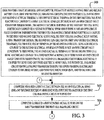
step 522, thecomputer 14 determines a first cell balancing current flowing through the firstcell balancing circuit 90 utilizing the following equation: first cell balancing current = (first voltage - second voltage) / (2 * first resistance value). Afterstep 522, the method advances to step 524. - At
step 524, thecomputer 14 makes a determination as to whether the first cell balancing current is greater than a first threshold current. If the value ofstep 524 equals "yes", the method advances to step 526. Otherwise, the method advances to step 528. - At
step 526, thecomputer 14 determines that a first open circuit fault condition is present between thefirst battery cell 20 and the firstcell balancing circuit 90, and stores a first fault value indicating the first open circuit fault condition, in thememory device 107. Afterstep 526, the method advances to step 540. - Referring again to step 524, if the
value step 524 equals "no", the method advances to step 528. Atstep 528, thecomputer 14 makes a determination as to whether the first cell balancing current is less than a second threshold current, wherein the second threshold current is less than the first threshold current. If the value ofstep 528 equals "yes", the method advances to step 530. Otherwise, the method advances to step 540. - At
step 530, thecomputer 14 determines an operational failure of thetransistor 190 in the firstcell balancing circuit 90, and stores a second fault value indicating the operational failure of thetransistor 190, in thememory device 107. Afterstep 530, the method advances to step 540. - At
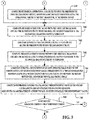
step 540, thecomputer 14 measures a third voltage between the thirdelectrical sense line 103 and the secondelectrical sense line 102 while thetransistor 290 in the secondcell balancing circuit 92 is turned off. Afterstep 540, the method advances to step 542. - At
step 542, thecomputer 14 generates a second control signal to turn on thetransistor 290 in the secondcell balancing circuit 92. Afterstep 542, the method advances to step 544. - At
step 544, thecomputer 14 measures a fourth voltage between the thirdelectrical sense line 103 and the secondelectrical sense line 102 while thetransistor 290 in the secondcell balancing circuit 92 is turned on. Afterstep 544, the method advances to step 546. - At
step 546, thecomputer 14 retrieves a second resistance value from the table 450 stored in thememory device 107. The second resistance value corresponds to a previously measured resistance level of a second conductive path coupled to and between thesecond battery cell 22 and the secondcell balancing circuit 92. Afterstep 546, the method advances to step 548. - At
step 548, thecomputer 14 determines a second cell balancing current flowing through the second cell balancing circuit utilizing the following equation: second cell balancing current = (third voltage - fourth voltage) / (2 * second resistance value). Afterstep 548, the method advances to step 550. - At
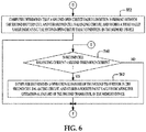
step 550, thecomputer 14 makes a determination as to whether the second cell balancing current is greater than the first threshold current. If the value ofstep 550 equals "yes", the method advancesstep 552. Otherwise, the method advances to step 560. - At
step 552, thecomputer 14 determines a second open circuit fault condition between thesecond battery cell 22 and the secondcell balancing circuit 92, and stores a third fault value indicating the second open circuit fault condition, in thememory device 107. Afterstep 552, the method returns to step 502. - Referring again to step 550, if the
value step 550 equals "no", the method advances to step 560. Atstep 560, thecomputer 14 makes a determination as to whether the second cell balancing current is less than the second threshold current. If the value ofstep 560 equals "yes", the method advances to step 562. Otherwise, the method returns to step 502. - At
step 562, thecomputer 14 determines an operational failure of thetransistor 290 in the secondcell balancing circuit 92, and stores a fourth fault value indicating the operational failure of thetransistor 290, in thememory device 107. Afterstep 562, the method returns to step 502. - The above-described method can be at least partially embodied in the form of one or more memory devices or computer readable media having computer-executable instructions for practicing the methods. The memory devices can comprise one or more of the following: hard drives, RAM memory, flash memory, and other computer-readable media known to those skilled in the art; wherein, when the computer-executable instructions are loaded into and executed by one or more computers or computers, the one or more computers or computers become an apparatus programmed to practice the associated steps of the method.
- The battery system and the method described herein provide a substantial advantage over other battery systems and methods. In particular, an advantage of the battery system is that battery system is adapted to determine an open circuit fault condition between a first battery cell and a first balancing circuit in a battery module based on a resistance of a conductive path between the first battery cell and the first balancing circuit, and an open circuit fault condition between a second battery cell and a second balancing circuit based on a resistance of a conductive path between the second battery cell and the second balancing circuit. Further, the battery system is adapted to determine an operational failure of a transistor in the first balancing circuit, and an operational failure of a transistor in the second balancing circuit.
- While the claimed invention has been described in detail in connection with only a limited number of embodiments, it should be readily understood that the invention is not limited to such disclosed embodiments. Rather, the claimed invention can be modified to incorporate any number of variations, alterations, substitutions or equivalent arrangements not heretofore described, but which are commensurate with the spirit and scope of the invention. Additionally, while various embodiments of the claimed invention have been described, it is to be understood that aspects of the invention may include only some of the described embodiments. Accordingly, the claimed invention is not to be seen as limited by the foregoing description.
- As explained above, the battery system according to the present invention can detect an open circuit fault condition between a battery cell and a cell balancing circuit in a battery module.
Claims (12)
- A battery system, comprising:a battery module having a first battery cell, a first cell balancing circuit, a second battery cell, and a second balancing circuit;the first battery cell having first and second electrical terminals, the first electrical terminal of the first battery cell being electrically coupled to a first electrical sense line if there is not an open circuit fault condition therebetween, the second electrical terminal of the first battery cell being electrically coupled to a second electrical sense line if there is not an open circuit fault condition therebetween;the first cell balancing circuit being electrically coupled to the first and second electrical sense lines, the first cell balancing circuit having a first transistor therein;the second battery cell having first and second electrical terminals, the first electrical terminal of the second battery cell being electrically coupled to the second electrical sense line if there is not an open circuit fault condition therebetween, the second electrical terminal of the second battery cell being electrically coupled to a third electrical sense line if there is not an open circuit fault condition therebetween;the second cell balancing circuit being electrically coupled to the second and third electrical sense lines, the second cell balancing circuit having a second transistor therein;a computer being electrically coupled to the first, second, and third electrical sense lines, and to the first and second transistors;the computer programmed to measure a first voltage between the second electrical sense line and the first electrical sense line while the first transistor in the first cell balancing circuit is turned off;the computer further programmed to generate a first control signal to turn on the first transistor in the first cell balancing circuit;the computer further programmed to measure a second voltage between the second electrical sense line and the first electrical sense line while the first transistor in the first cell balancing circuit is turned on;the computer further programmed to retrieve a first resistance value from a table stored in a memory device, the first resistance value corresponding to a previously measured resistance level of a first conductive path coupled to and between the first battery cell and the first cell balancing circuit;the computer further programmed to determine a first cell balancing current flowing through the first cell balancing circuit based on the first and second voltages and the first resistance value; andthe computer further programmed to determine a first open circuit fault condition between the first battery cell and the first cell balancing circuit if the first cell balancing current is greater than a first threshold current.
- The battery system of claim 1, wherein the computer further programmed to determine an operational failure of the first transistor in the first cell balancing circuit if the first cell balancing current is less than a second threshold current, the second threshold current being less than the first threshold current.
- The battery system of claim 2, wherein:the computer further programmed to store a first fault value indicating the first open circuit fault condition between the first battery cell and the first cell balancing circuit, in the memory device; andthe computer further programmed to store a second fault value indicating the operational failure of the first transistor in the first cell balancing circuit, in the memory device.
- The battery system of claim 1, wherein the first conductive path being coupled to and between the first electrical terminal of the first battery cell and the first cell balancing circuit; and
the computer further programmed to determine the first open circuit fault condition in either the first conductive path coupled to and between the first electrical terminal of the first battery cell and the first cell balancing circuit, or in a second conductive path coupled to and between the second electrical terminal of the first battery cell and the first cell balancing circuit, if the first cell balancing current is greater than the first threshold current. - The battery system of claim 1, wherein:the computer further programmed to measure a third voltage between the third electrical sense line and the second electrical sense line while the second transistor in the second cell balancing circuit is turned off;the computer further programmed to generate a second control signal to turn on the second transistor in the second cell balancing circuit;the computer further programmed to measure a fourth voltage between the third electrical sense line and the second electrical sense line while the second transistor in the second cell balancing circuit is turned on;the computer further programmed to retrieve a second resistance value from the table stored in the memory device, the second resistance value corresponding to a previously measured resistance level of a second conductive path coupled to and between the second battery cell and the second cell balancing circuit;the computer further programmed to determine a second cell balancing current flowing through the second cell balancing circuit based on the third and fourth voltages and the second resistance value; andthe computer further programmed to determine a second open circuit fault condition between the second battery cell and the second cell balancing circuit if the second cell balancing current is greater than the first threshold current.
- The battery system of claim 5, wherein the computer further programmed to determine an operational failure of the second transistor in the second cell balancing circuit if the second cell balancing current is less than the second threshold current.
- A method for determining an open circuit fault condition in a battery module, comprising:providing the battery module and a computer, the battery module having first and second battery cells, and first and second cell balancing circuits; the first battery cell having first and second electrical terminals, the first electrical terminal of the first battery cell being electrically coupled to a first electrical sense line if there is not an open circuit fault condition therebetween, the second electrical terminal of the first battery cell being electrically coupled to a second electrical sense line if there is not an open circuit fault condition therebetween; the first cell balancing circuit being electrically coupled to the first and second electrical sense lines, the first cell balancing circuit having a first transistor therein; the second battery cell having first and second electrical terminals, the first electrical terminal of the second battery cell being electrically coupled to the second electrical sense line if there is not an open circuit fault condition therebetween, the second electrical terminal of the second battery cell being electrically coupled to a third electrical sense line if there is not an open circuit fault condition therebetween; the second cell balancing circuit being electrically coupled to the second and third electrical sense lines, the second cell balancing circuit having a second transistor therein; the computer being electrically coupled to the first, second, and third electrical sense lines, and to the first and second transistors;measuring a first voltage between the second electrical sense line and the first electrical sense line while the first transistor in the first cell balancing circuit is turned off, utilizing the computer;generating a first control signal to turn on the first transistor in the first cell balancing circuit utilizing the computer;measuring a second voltage between the second electrical sense line and the first electrical sense line while the first transistor in the first cell balancing circuit is turned on, utilizing the computer;retrieving a first resistance value from a table stored in a memory device, utilizing the computer; the first resistance value corresponding to a previously measured resistance level of a first conductive path coupled to and between the first battery cell and the first cell balancing circuit;determining a first cell balancing current flowing through the first cell balancing circuit based on the first and second voltages and the first resistance value, utilizing the computer; anddetermining a first open circuit fault condition between the first battery cell and the first cell balancing circuit if the first cell balancing current is greater than a first threshold current, utilizing the computer.
- The method of claim 7, further comprising storing a first fault value indicating the first open circuit fault condition between the first battery cell and the first cell balancing circuit in the memory device, utilizing the computer.
- The method of claim 7, further comprising determining an operational failure of the first transistor in the first cell balancing circuit if the first cell balancing current is less than a second threshold current, utilizing the computer; the second threshold current being less than the first threshold current.
- The method of claim 9, further comprising storing a second fault value indicating the operational failure of the first transistor in the first cell balancing circuit in the memory device, utilizing the computer.
- The method of claim 7, further comprising:measuring a third voltage between the third electrical sense line and the second electrical sense line while the second transistor in the second cell balancing circuit is turned off, utilizing the computer;generating a second control signal to turn on the second transistor in the second cell balancing circuit, utilizing the computer;measuring a fourth voltage between the third electrical sense line and the second electrical sense line while the second transistor in the second cell balancing circuit is turned on, utilizing the computer;retrieving a second resistance value from the table stored in the memory device, utilizing the computer, the second resistance value corresponding to a previously measured resistance level of a second conductive path coupled to and between the second battery cell and the second cell balancing circuit;determining a second cell balancing current flowing through the second cell balancing circuit based on the third and fourth voltages and the second resistance value, utilizing the computer; anddetermining a second open circuit fault condition between the second battery cell and the second cell balancing circuit if the second cell balancing current is greater than the first threshold current, utilizing the computer.
- The method of claim 11, further comprising determining an operational failure of the second transistor in the second cell balancing circuit if the second cell balancing current is less than the second threshold current, utilizing the computer.
Applications Claiming Priority (2)
| Application Number | Priority Date | Filing Date | Title |
|---|---|---|---|
| US15/070,834 US9876369B2 (en) | 2016-03-15 | 2016-03-15 | Battery system and method for determining an open circuit fault condition in a battery module |
| PCT/KR2017/002669 WO2017160035A1 (en) | 2016-03-15 | 2017-03-13 | Battery system and method for determining open circuit defect state of battery module |
Publications (3)
| Publication Number | Publication Date |
|---|---|
| EP3301466A1 true EP3301466A1 (en) | 2018-04-04 |
| EP3301466A4 EP3301466A4 (en) | 2018-06-20 |
| EP3301466B1 EP3301466B1 (en) | 2022-05-18 |
Family
ID=59851719
Family Applications (1)
| Application Number | Title | Priority Date | Filing Date |
|---|---|---|---|
| EP17766936.3A Active EP3301466B1 (en) | 2016-03-15 | 2017-03-13 | Battery system and method for determining open circuit defect state of battery module |
Country Status (6)
| Country | Link |
|---|---|
| US (1) | US9876369B2 (en) |
| EP (1) | EP3301466B1 (en) |
| JP (1) | JP6755302B2 (en) |
| KR (1) | KR101975481B1 (en) |
| CN (1) | CN107710007B (en) |
| WO (1) | WO2017160035A1 (en) |
Families Citing this family (10)
| Publication number | Priority date | Publication date | Assignee | Title |
|---|---|---|---|---|
| US10063068B1 (en) * | 2017-04-11 | 2018-08-28 | Lg Chem, Ltd. | Battery system |
| KR102407454B1 (en) * | 2018-06-29 | 2022-06-10 | 주식회사 엘지에너지솔루션 | Apparatus and method for testing a battery circuit board |
| KR102443667B1 (en) * | 2018-10-26 | 2022-09-14 | 주식회사 엘지에너지솔루션 | balancing apparatus, and battery management system and battery pack including the same |
| US10978751B2 (en) * | 2019-03-13 | 2021-04-13 | Lg Chem, Ltd. | Battery system |
| US11418041B2 (en) * | 2019-03-15 | 2022-08-16 | Lg Energy Solution, Ltd. | Battery system |
| EP3822645B1 (en) | 2019-11-18 | 2022-10-26 | Volvo Car Corporation | System and method for detecting failures in a battery management system for a vehicle battery |
| CN110764006B (en) * | 2019-12-30 | 2020-10-27 | 杭州华塑加达网络科技有限公司 | Battery management system |
| FR3112862B1 (en) * | 2020-07-27 | 2022-11-25 | Limatech | Semi-modular storage battery management system |
| CN112109589B (en) * | 2020-09-22 | 2021-12-28 | 一汽解放汽车有限公司 | Battery fault processing method and device, vehicle and storage medium |
| KR20220120165A (en) * | 2021-02-23 | 2022-08-30 | 삼성에스디아이 주식회사 | Battery management system |
Family Cites Families (20)
| Publication number | Priority date | Publication date | Assignee | Title |
|---|---|---|---|---|
| US5804944A (en) * | 1997-04-07 | 1998-09-08 | Motorola, Inc. | Battery protection system and process for charging a battery |
| JP4254209B2 (en) * | 2002-11-22 | 2009-04-15 | 新神戸電機株式会社 | Battery voltage detection line inspection method, inspection circuit, and battery module |
| US9000771B2 (en) | 2008-11-14 | 2015-04-07 | Honda Motor Co., Ltd. | Automotive battery circuit fault detection |
| EP2291670B1 (en) * | 2008-06-27 | 2021-04-21 | Clarios Advanced Solutions LLC | Cell diagnostic system and method |
| JP5486822B2 (en) | 2009-02-17 | 2014-05-07 | 株式会社日立製作所 | Battery system |
| JP2010271267A (en) * | 2009-05-25 | 2010-12-02 | Mitsubishi Motors Corp | Battery monitoring device |
| JP5382138B2 (en) * | 2009-12-25 | 2014-01-08 | トヨタ自動車株式会社 | Abnormality detection device for battery pack |
| KR101093888B1 (en) | 2009-12-28 | 2011-12-13 | 삼성에스디아이 주식회사 | Battery pack and its disconnection detection method |
| KR101138507B1 (en) * | 2010-07-19 | 2012-04-25 | 삼성전기주식회사 | Solar cell system |
| US8587318B2 (en) * | 2010-07-27 | 2013-11-19 | GM Global Technology Operations LLC | Sensor arrangement for an energy storage device and a method of using the same |
| JP5911673B2 (en) | 2010-07-30 | 2016-04-27 | 三洋電機株式会社 | Power supply |
| US20120119709A1 (en) * | 2010-11-17 | 2012-05-17 | Tenergy Corporation | Battery pack balancing circuit |
| JP2012160230A (en) * | 2011-01-31 | 2012-08-23 | Elpida Memory Inc | Semiconductor device |
| US9885757B2 (en) | 2011-04-01 | 2018-02-06 | Atieva, Inc. | Method and apparatus for determining the state-of-charge of a battery |
| US9340122B2 (en) * | 2011-05-31 | 2016-05-17 | Hitachi Automotive Systems, Ltd. | Battery system monitoring apparatus |
| US9097774B2 (en) | 2011-07-14 | 2015-08-04 | Southwest Electronic Energy Corporation | Short detection in battery cells |
| JP2014143853A (en) * | 2013-01-24 | 2014-08-07 | Hitachi Ulsi Systems Co Ltd | Power storage device and battery monitoring device |
| KR101562016B1 (en) * | 2013-08-29 | 2015-11-18 | 주식회사 엘지화학 | Apparatus and Method for diagnosis of cell balancing switch |
| US9537329B2 (en) * | 2014-08-29 | 2017-01-03 | General Electronics Applications, Inc. | Battery management circuit maintaining cell voltages between a minimum and a maximum during charging and discharging |
| WO2017143514A1 (en) * | 2016-02-23 | 2017-08-31 | Texas Instruments Incorporated | Battery apparatus and cell balancing circuits |
-
2016
- 2016-03-15 US US15/070,834 patent/US9876369B2/en active Active
-
2017
- 2017-03-13 WO PCT/KR2017/002669 patent/WO2017160035A1/en not_active Ceased
- 2017-03-13 CN CN201780002225.2A patent/CN107710007B/en active Active
- 2017-03-13 EP EP17766936.3A patent/EP3301466B1/en active Active
- 2017-03-13 JP JP2018503786A patent/JP6755302B2/en active Active
- 2017-03-13 KR KR1020177034781A patent/KR101975481B1/en active Active
Also Published As
| Publication number | Publication date |
|---|---|
| WO2017160035A1 (en) | 2017-09-21 |
| JP2018529082A (en) | 2018-10-04 |
| US9876369B2 (en) | 2018-01-23 |
| CN107710007A (en) | 2018-02-16 |
| US20170271888A1 (en) | 2017-09-21 |
| EP3301466B1 (en) | 2022-05-18 |
| EP3301466A4 (en) | 2018-06-20 |
| KR101975481B1 (en) | 2019-05-07 |
| JP6755302B2 (en) | 2020-09-16 |
| CN107710007B (en) | 2019-12-10 |
| KR20170139682A (en) | 2017-12-19 |
Similar Documents
| Publication | Publication Date | Title |
|---|---|---|
| EP3301466B1 (en) | Battery system and method for determining open circuit defect state of battery module | |
| US11927642B2 (en) | Open cell detection method and open cell recovery detection method in a battery management system | |
| KR102055858B1 (en) | Vehicles with diagnostic system for electrical fuses | |
| US10063068B1 (en) | Battery system | |
| US11777154B2 (en) | Battery management systems and methods, and open cell detection systems | |
| US10978751B2 (en) | Battery system | |
| CN110658481B (en) | Grounding loss detection system | |
| JP6016754B2 (en) | Battery voltage detector | |
| JP2019158539A (en) | Battery monitoring device | |
| US11418041B2 (en) | Battery system | |
| CN113015919B (en) | Wire break sensing device and wire break sensing method | |
| KR20200031647A (en) | Systems and methods for diagnosing electrical faults | |
| US12500280B2 (en) | Device and method for monitoring at least three battery cells of a battery | |
| JP6491965B2 (en) | Inspection method and inspection apparatus for battery monitoring unit | |
| KR102324968B1 (en) | System and method for diagnosing the connectivity of fuses, bms including a system for diagnosing the connectivity of fuses | |
| US20210257847A1 (en) | Battery control device, battery control method, control program, and vehicle | |
| US10816609B2 (en) | Open circuit detection for vehicle power system | |
| CN112462203A (en) | Power battery insulation detection method and related device | |
| EP3534485A1 (en) | Battery pack, battery management system, and method therefor | |
| KR102861557B1 (en) | Method for diagnosing failure of circuit for power input, and system thereof | |
| KR20230151030A (en) | How to check the insulation of a battery or battery system | |
| JP2020060436A (en) | Battery monitoring device | |
| JP2016103444A (en) | Battery monitoring apparatus | |
| CN206756938U (en) | The detecting system of power capacitor | |
| KR20170053529A (en) | Method and system of capacitor crack in battery back |
Legal Events
| Date | Code | Title | Description |
|---|---|---|---|
| STAA | Information on the status of an ep patent application or granted ep patent |
Free format text: STATUS: THE INTERNATIONAL PUBLICATION HAS BEEN MADE |
|
| PUAI | Public reference made under article 153(3) epc to a published international application that has entered the european phase |
Free format text: ORIGINAL CODE: 0009012 |
|
| STAA | Information on the status of an ep patent application or granted ep patent |
Free format text: STATUS: REQUEST FOR EXAMINATION WAS MADE |
|
| 17P | Request for examination filed |
Effective date: 20171227 |
|
| AK | Designated contracting states |
Kind code of ref document: A1 Designated state(s): AL AT BE BG CH CY CZ DE DK EE ES FI FR GB GR HR HU IE IS IT LI LT LU LV MC MK MT NL NO PL PT RO RS SE SI SK SM TR |
|
| AX | Request for extension of the european patent |
Extension state: BA ME |
|
| A4 | Supplementary search report drawn up and despatched |
Effective date: 20180523 |
|
| RIC1 | Information provided on ipc code assigned before grant |
Ipc: G01R 31/36 20060101AFI20180516BHEP Ipc: H02J 7/00 20060101ALI20180516BHEP |
|
| DAV | Request for validation of the european patent (deleted) | ||
| DAX | Request for extension of the european patent (deleted) | ||
| STAA | Information on the status of an ep patent application or granted ep patent |
Free format text: STATUS: EXAMINATION IS IN PROGRESS |
|
| 17Q | First examination report despatched |
Effective date: 20210218 |
|
| REG | Reference to a national code |
Ref country code: DE Ref legal event code: R079 Ref document number: 602017057649 Country of ref document: DE Free format text: PREVIOUS MAIN CLASS: G01R0031360000 Ipc: G01R0031396000 |
|
| RIC1 | Information provided on ipc code assigned before grant |
Ipc: H02J 7/00 20060101ALI20211012BHEP Ipc: G01R 31/54 20200101ALI20211012BHEP Ipc: G01R 31/52 20200101ALI20211012BHEP Ipc: G01R 31/396 20190101AFI20211012BHEP |
|
| GRAP | Despatch of communication of intention to grant a patent |
Free format text: ORIGINAL CODE: EPIDOSNIGR1 |
|
| STAA | Information on the status of an ep patent application or granted ep patent |
Free format text: STATUS: GRANT OF PATENT IS INTENDED |
|
| INTG | Intention to grant announced |
Effective date: 20211129 |
|
| RAP1 | Party data changed (applicant data changed or rights of an application transferred) |
Owner name: LG ENERGY SOLUTION LTD. |
|
| GRAS | Grant fee paid |
Free format text: ORIGINAL CODE: EPIDOSNIGR3 |
|
| GRAJ | Information related to disapproval of communication of intention to grant by the applicant or resumption of examination proceedings by the epo deleted |
Free format text: ORIGINAL CODE: EPIDOSDIGR1 |
|
| GRAL | Information related to payment of fee for publishing/printing deleted |
Free format text: ORIGINAL CODE: EPIDOSDIGR3 |
|
| STAA | Information on the status of an ep patent application or granted ep patent |
Free format text: STATUS: EXAMINATION IS IN PROGRESS |
|
| INTC | Intention to grant announced (deleted) | ||
| RAP3 | Party data changed (applicant data changed or rights of an application transferred) |
Owner name: LG ENERGY SOLUTION, LTD. |
|
| GRAP | Despatch of communication of intention to grant a patent |
Free format text: ORIGINAL CODE: EPIDOSNIGR1 |
|
| STAA | Information on the status of an ep patent application or granted ep patent |
Free format text: STATUS: GRANT OF PATENT IS INTENDED |
|
| GRAS | Grant fee paid |
Free format text: ORIGINAL CODE: EPIDOSNIGR3 |
|
| GRAA | (expected) grant |
Free format text: ORIGINAL CODE: 0009210 |
|
| STAA | Information on the status of an ep patent application or granted ep patent |
Free format text: STATUS: THE PATENT HAS BEEN GRANTED |
|
| INTG | Intention to grant announced |
Effective date: 20220405 |
|
| AK | Designated contracting states |
Kind code of ref document: B1 Designated state(s): AL AT BE BG CH CY CZ DE DK EE ES FI FR GB GR HR HU IE IS IT LI LT LU LV MC MK MT NL NO PL PT RO RS SE SI SK SM TR |
|
| REG | Reference to a national code |
Ref country code: GB Ref legal event code: FG4D |
|
| REG | Reference to a national code |
Ref country code: CH Ref legal event code: EP |
|
| REG | Reference to a national code |
Ref country code: IE Ref legal event code: FG4D |
|
| REG | Reference to a national code |
Ref country code: DE Ref legal event code: R096 Ref document number: 602017057649 Country of ref document: DE |
|
| REG | Reference to a national code |
Ref country code: AT Ref legal event code: REF Ref document number: 1493460 Country of ref document: AT Kind code of ref document: T Effective date: 20220615 |
|
| REG | Reference to a national code |
Ref country code: LT Ref legal event code: MG9D |
|
| REG | Reference to a national code |
Ref country code: NL Ref legal event code: MP Effective date: 20220518 |
|
| REG | Reference to a national code |
Ref country code: AT Ref legal event code: MK05 Ref document number: 1493460 Country of ref document: AT Kind code of ref document: T Effective date: 20220518 |
|
| PG25 | Lapsed in a contracting state [announced via postgrant information from national office to epo] |
Ref country code: SE Free format text: LAPSE BECAUSE OF FAILURE TO SUBMIT A TRANSLATION OF THE DESCRIPTION OR TO PAY THE FEE WITHIN THE PRESCRIBED TIME-LIMIT Effective date: 20220518 Ref country code: PT Free format text: LAPSE BECAUSE OF FAILURE TO SUBMIT A TRANSLATION OF THE DESCRIPTION OR TO PAY THE FEE WITHIN THE PRESCRIBED TIME-LIMIT Effective date: 20220919 Ref country code: NO Free format text: LAPSE BECAUSE OF FAILURE TO SUBMIT A TRANSLATION OF THE DESCRIPTION OR TO PAY THE FEE WITHIN THE PRESCRIBED TIME-LIMIT Effective date: 20220818 Ref country code: NL Free format text: LAPSE BECAUSE OF FAILURE TO SUBMIT A TRANSLATION OF THE DESCRIPTION OR TO PAY THE FEE WITHIN THE PRESCRIBED TIME-LIMIT Effective date: 20220518 Ref country code: LT Free format text: LAPSE BECAUSE OF FAILURE TO SUBMIT A TRANSLATION OF THE DESCRIPTION OR TO PAY THE FEE WITHIN THE PRESCRIBED TIME-LIMIT Effective date: 20220518 Ref country code: HR Free format text: LAPSE BECAUSE OF FAILURE TO SUBMIT A TRANSLATION OF THE DESCRIPTION OR TO PAY THE FEE WITHIN THE PRESCRIBED TIME-LIMIT Effective date: 20220518 Ref country code: GR Free format text: LAPSE BECAUSE OF FAILURE TO SUBMIT A TRANSLATION OF THE DESCRIPTION OR TO PAY THE FEE WITHIN THE PRESCRIBED TIME-LIMIT Effective date: 20220819 Ref country code: FI Free format text: LAPSE BECAUSE OF FAILURE TO SUBMIT A TRANSLATION OF THE DESCRIPTION OR TO PAY THE FEE WITHIN THE PRESCRIBED TIME-LIMIT Effective date: 20220518 Ref country code: ES Free format text: LAPSE BECAUSE OF FAILURE TO SUBMIT A TRANSLATION OF THE DESCRIPTION OR TO PAY THE FEE WITHIN THE PRESCRIBED TIME-LIMIT Effective date: 20220518 Ref country code: BG Free format text: LAPSE BECAUSE OF FAILURE TO SUBMIT A TRANSLATION OF THE DESCRIPTION OR TO PAY THE FEE WITHIN THE PRESCRIBED TIME-LIMIT Effective date: 20220818 Ref country code: AT Free format text: LAPSE BECAUSE OF FAILURE TO SUBMIT A TRANSLATION OF THE DESCRIPTION OR TO PAY THE FEE WITHIN THE PRESCRIBED TIME-LIMIT Effective date: 20220518 |
|
| PG25 | Lapsed in a contracting state [announced via postgrant information from national office to epo] |
Ref country code: RS Free format text: LAPSE BECAUSE OF FAILURE TO SUBMIT A TRANSLATION OF THE DESCRIPTION OR TO PAY THE FEE WITHIN THE PRESCRIBED TIME-LIMIT Effective date: 20220518 Ref country code: PL Free format text: LAPSE BECAUSE OF FAILURE TO SUBMIT A TRANSLATION OF THE DESCRIPTION OR TO PAY THE FEE WITHIN THE PRESCRIBED TIME-LIMIT Effective date: 20220518 Ref country code: LV Free format text: LAPSE BECAUSE OF FAILURE TO SUBMIT A TRANSLATION OF THE DESCRIPTION OR TO PAY THE FEE WITHIN THE PRESCRIBED TIME-LIMIT Effective date: 20220518 Ref country code: IS Free format text: LAPSE BECAUSE OF FAILURE TO SUBMIT A TRANSLATION OF THE DESCRIPTION OR TO PAY THE FEE WITHIN THE PRESCRIBED TIME-LIMIT Effective date: 20220918 |
|
| PG25 | Lapsed in a contracting state [announced via postgrant information from national office to epo] |
Ref country code: SM Free format text: LAPSE BECAUSE OF FAILURE TO SUBMIT A TRANSLATION OF THE DESCRIPTION OR TO PAY THE FEE WITHIN THE PRESCRIBED TIME-LIMIT Effective date: 20220518 Ref country code: SK Free format text: LAPSE BECAUSE OF FAILURE TO SUBMIT A TRANSLATION OF THE DESCRIPTION OR TO PAY THE FEE WITHIN THE PRESCRIBED TIME-LIMIT Effective date: 20220518 Ref country code: RO Free format text: LAPSE BECAUSE OF FAILURE TO SUBMIT A TRANSLATION OF THE DESCRIPTION OR TO PAY THE FEE WITHIN THE PRESCRIBED TIME-LIMIT Effective date: 20220518 Ref country code: EE Free format text: LAPSE BECAUSE OF FAILURE TO SUBMIT A TRANSLATION OF THE DESCRIPTION OR TO PAY THE FEE WITHIN THE PRESCRIBED TIME-LIMIT Effective date: 20220518 Ref country code: DK Free format text: LAPSE BECAUSE OF FAILURE TO SUBMIT A TRANSLATION OF THE DESCRIPTION OR TO PAY THE FEE WITHIN THE PRESCRIBED TIME-LIMIT Effective date: 20220518 Ref country code: CZ Free format text: LAPSE BECAUSE OF FAILURE TO SUBMIT A TRANSLATION OF THE DESCRIPTION OR TO PAY THE FEE WITHIN THE PRESCRIBED TIME-LIMIT Effective date: 20220518 |
|
| REG | Reference to a national code |
Ref country code: DE Ref legal event code: R097 Ref document number: 602017057649 Country of ref document: DE |
|
| PLBE | No opposition filed within time limit |
Free format text: ORIGINAL CODE: 0009261 |
|
| STAA | Information on the status of an ep patent application or granted ep patent |
Free format text: STATUS: NO OPPOSITION FILED WITHIN TIME LIMIT |
|
| PG25 | Lapsed in a contracting state [announced via postgrant information from national office to epo] |
Ref country code: AL Free format text: LAPSE BECAUSE OF FAILURE TO SUBMIT A TRANSLATION OF THE DESCRIPTION OR TO PAY THE FEE WITHIN THE PRESCRIBED TIME-LIMIT Effective date: 20220518 |
|
| 26N | No opposition filed |
Effective date: 20230221 |
|
| PG25 | Lapsed in a contracting state [announced via postgrant information from national office to epo] |
Ref country code: SI Free format text: LAPSE BECAUSE OF FAILURE TO SUBMIT A TRANSLATION OF THE DESCRIPTION OR TO PAY THE FEE WITHIN THE PRESCRIBED TIME-LIMIT Effective date: 20220518 |
|
| P01 | Opt-out of the competence of the unified patent court (upc) registered |
Effective date: 20230512 |
|
| PG25 | Lapsed in a contracting state [announced via postgrant information from national office to epo] |
Ref country code: MC Free format text: LAPSE BECAUSE OF FAILURE TO SUBMIT A TRANSLATION OF THE DESCRIPTION OR TO PAY THE FEE WITHIN THE PRESCRIBED TIME-LIMIT Effective date: 20220518 |
|
| REG | Reference to a national code |
Ref country code: CH Ref legal event code: PL |
|
| REG | Reference to a national code |
Ref country code: BE Ref legal event code: MM Effective date: 20230331 |
|
| PG25 | Lapsed in a contracting state [announced via postgrant information from national office to epo] |
Ref country code: LU Free format text: LAPSE BECAUSE OF NON-PAYMENT OF DUE FEES Effective date: 20230313 |
|
| REG | Reference to a national code |
Ref country code: IE Ref legal event code: MM4A |
|
| PG25 | Lapsed in a contracting state [announced via postgrant information from national office to epo] |
Ref country code: LI Free format text: LAPSE BECAUSE OF NON-PAYMENT OF DUE FEES Effective date: 20230331 Ref country code: IT Free format text: LAPSE BECAUSE OF FAILURE TO SUBMIT A TRANSLATION OF THE DESCRIPTION OR TO PAY THE FEE WITHIN THE PRESCRIBED TIME-LIMIT Effective date: 20220518 Ref country code: IE Free format text: LAPSE BECAUSE OF NON-PAYMENT OF DUE FEES Effective date: 20230313 Ref country code: CH Free format text: LAPSE BECAUSE OF NON-PAYMENT OF DUE FEES Effective date: 20230331 |
|
| PG25 | Lapsed in a contracting state [announced via postgrant information from national office to epo] |
Ref country code: BE Free format text: LAPSE BECAUSE OF NON-PAYMENT OF DUE FEES Effective date: 20230331 |
|
| PG25 | Lapsed in a contracting state [announced via postgrant information from national office to epo] |
Ref country code: BG Free format text: LAPSE BECAUSE OF FAILURE TO SUBMIT A TRANSLATION OF THE DESCRIPTION OR TO PAY THE FEE WITHIN THE PRESCRIBED TIME-LIMIT Effective date: 20220518 |
|
| PG25 | Lapsed in a contracting state [announced via postgrant information from national office to epo] |
Ref country code: BG Free format text: LAPSE BECAUSE OF FAILURE TO SUBMIT A TRANSLATION OF THE DESCRIPTION OR TO PAY THE FEE WITHIN THE PRESCRIBED TIME-LIMIT Effective date: 20220518 |
|
| PG25 | Lapsed in a contracting state [announced via postgrant information from national office to epo] |
Ref country code: CY Free format text: LAPSE BECAUSE OF FAILURE TO SUBMIT A TRANSLATION OF THE DESCRIPTION OR TO PAY THE FEE WITHIN THE PRESCRIBED TIME-LIMIT; INVALID AB INITIO Effective date: 20170313 |
|
| PG25 | Lapsed in a contracting state [announced via postgrant information from national office to epo] |
Ref country code: HU Free format text: LAPSE BECAUSE OF FAILURE TO SUBMIT A TRANSLATION OF THE DESCRIPTION OR TO PAY THE FEE WITHIN THE PRESCRIBED TIME-LIMIT; INVALID AB INITIO Effective date: 20170313 |
|
| PG25 | Lapsed in a contracting state [announced via postgrant information from national office to epo] |
Ref country code: TR Free format text: LAPSE BECAUSE OF FAILURE TO SUBMIT A TRANSLATION OF THE DESCRIPTION OR TO PAY THE FEE WITHIN THE PRESCRIBED TIME-LIMIT Effective date: 20220518 |
|
| PGFP | Annual fee paid to national office [announced via postgrant information from national office to epo] |
Ref country code: GB Payment date: 20260224 Year of fee payment: 10 |
|
| PGFP | Annual fee paid to national office [announced via postgrant information from national office to epo] |
Ref country code: DE Payment date: 20260220 Year of fee payment: 10 |
|
| PGFP | Annual fee paid to national office [announced via postgrant information from national office to epo] |
Ref country code: FR Payment date: 20260224 Year of fee payment: 10 |