EP3301459A1 - Measurement device and configuration method - Google Patents
Measurement device and configuration method Download PDFInfo
- Publication number
- EP3301459A1 EP3301459A1 EP17152321.0A EP17152321A EP3301459A1 EP 3301459 A1 EP3301459 A1 EP 3301459A1 EP 17152321 A EP17152321 A EP 17152321A EP 3301459 A1 EP3301459 A1 EP 3301459A1
- Authority
- EP
- European Patent Office
- Prior art keywords
- parameter
- calculation
- measurement device
- value
- function
- Prior art date
- Legal status (The legal status is an assumption and is not a legal conclusion. Google has not performed a legal analysis and makes no representation as to the accuracy of the status listed.)
- Granted
Links
Images


Classifications
-
- G—PHYSICS
- G01—MEASURING; TESTING
- G01R—MEASURING ELECTRIC VARIABLES; MEASURING MAGNETIC VARIABLES
- G01R19/00—Arrangements for measuring currents or voltages or for indicating presence or sign thereof
- G01R19/25—Arrangements for measuring currents or voltages or for indicating presence or sign thereof using digital measurement techniques
- G01R19/2506—Arrangements for conditioning or analysing measured signals, e.g. for indicating peak values ; Details concerning sampling, digitizing or waveform capturing
-
- G—PHYSICS
- G01—MEASURING; TESTING
- G01D—MEASURING NOT SPECIALLY ADAPTED FOR A SPECIFIC VARIABLE; ARRANGEMENTS FOR MEASURING TWO OR MORE VARIABLES NOT COVERED IN A SINGLE OTHER SUBCLASS; TARIFF METERING APPARATUS; MEASURING OR TESTING NOT OTHERWISE PROVIDED FOR
- G01D11/00—Component parts of measuring arrangements not specially adapted for a specific variable
-
- G—PHYSICS
- G01—MEASURING; TESTING
- G01R—MEASURING ELECTRIC VARIABLES; MEASURING MAGNETIC VARIABLES
- G01R31/00—Arrangements for testing electric properties; Arrangements for locating electric faults; Arrangements for electrical testing characterised by what is being tested not provided for elsewhere
- G01R31/28—Testing of electronic circuits, e.g. by signal tracer
- G01R31/317—Testing of digital circuits
- G01R31/3181—Functional testing
- G01R31/319—Tester hardware, i.e. output processing circuits
- G01R31/31903—Tester hardware, i.e. output processing circuits tester configuration
- G01R31/31912—Tester/user interface
-
- G—PHYSICS
- G01—MEASURING; TESTING
- G01R—MEASURING ELECTRIC VARIABLES; MEASURING MAGNETIC VARIABLES
- G01R1/00—Details of instruments or arrangements of the types included in groups G01R5/00 - G01R13/00 and G01R31/00
- G01R1/02—General constructional details
- G01R1/025—General constructional details concerning dedicated user interfaces, e.g. GUI, or dedicated keyboards
-
- G—PHYSICS
- G01—MEASURING; TESTING
- G01R—MEASURING ELECTRIC VARIABLES; MEASURING MAGNETIC VARIABLES
- G01R13/00—Arrangements for displaying electric variables or waveforms
- G01R13/02—Arrangements for displaying electric variables or waveforms for displaying measured electric variables in digital form
-
- G—PHYSICS
- G01—MEASURING; TESTING
- G01R—MEASURING ELECTRIC VARIABLES; MEASURING MAGNETIC VARIABLES
- G01R13/00—Arrangements for displaying electric variables or waveforms
- G01R13/02—Arrangements for displaying electric variables or waveforms for displaying measured electric variables in digital form
- G01R13/029—Software therefor
-
- G—PHYSICS
- G01—MEASURING; TESTING
- G01R—MEASURING ELECTRIC VARIABLES; MEASURING MAGNETIC VARIABLES
- G01R13/00—Arrangements for displaying electric variables or waveforms
- G01R13/20—Cathode-ray oscilloscopes
- G01R13/22—Circuits therefor
- G01R13/34—Circuits for representing a single waveform by sampling, e.g. for very high frequencies
-
- G—PHYSICS
- G01—MEASURING; TESTING
- G01R—MEASURING ELECTRIC VARIABLES; MEASURING MAGNETIC VARIABLES
- G01R15/00—Details of measuring arrangements of the types provided for in groups G01R17/00 - G01R29/00, G01R33/00 - G01R33/26 or G01R35/00
- G01R15/04—Voltage dividers
-
- G—PHYSICS
- G01—MEASURING; TESTING
- G01R—MEASURING ELECTRIC VARIABLES; MEASURING MAGNETIC VARIABLES
- G01R19/00—Arrangements for measuring currents or voltages or for indicating presence or sign thereof
- G01R19/10—Measuring sum, difference or ratio
-
- G—PHYSICS
- G01—MEASURING; TESTING
- G01R—MEASURING ELECTRIC VARIABLES; MEASURING MAGNETIC VARIABLES
- G01R31/00—Arrangements for testing electric properties; Arrangements for locating electric faults; Arrangements for electrical testing characterised by what is being tested not provided for elsewhere
- G01R31/28—Testing of electronic circuits, e.g. by signal tracer
- G01R31/2832—Specific tests of electronic circuits not provided for elsewhere
- G01R31/2834—Automated test systems [ATE]; using microprocessors or computers
-
- G—PHYSICS
- G06—COMPUTING OR CALCULATING; COUNTING
- G06F—ELECTRIC DIGITAL DATA PROCESSING
- G06F11/00—Error detection; Error correction; Monitoring
- G06F11/30—Monitoring
- G06F11/32—Monitoring with visual or acoustical indication of the functioning of the machine
- G06F11/321—Display for diagnostics, e.g. diagnostic result display, self-test user interface
- G06F11/322—Display of waveforms, e.g. of logic analysers
-
- G—PHYSICS
- G06—COMPUTING OR CALCULATING; COUNTING
- G06F—ELECTRIC DIGITAL DATA PROCESSING
- G06F7/00—Methods or arrangements for processing data by operating upon the order or content of the data handled
- G06F7/38—Methods or arrangements for performing computations using exclusively denominational number representation, e.g. using binary, ternary, decimal representation
- G06F7/48—Methods or arrangements for performing computations using exclusively denominational number representation, e.g. using binary, ternary, decimal representation using non-contact-making devices, e.g. tube, solid state device; using unspecified devices
- G06F7/50—Adding; Subtracting
-
- G—PHYSICS
- G06—COMPUTING OR CALCULATING; COUNTING
- G06F—ELECTRIC DIGITAL DATA PROCESSING
- G06F7/00—Methods or arrangements for processing data by operating upon the order or content of the data handled
- G06F7/38—Methods or arrangements for performing computations using exclusively denominational number representation, e.g. using binary, ternary, decimal representation
- G06F7/48—Methods or arrangements for performing computations using exclusively denominational number representation, e.g. using binary, ternary, decimal representation using non-contact-making devices, e.g. tube, solid state device; using unspecified devices
- G06F7/52—Multiplying; Dividing
Definitions
- the present invention relates to a measurement device.
- the present invention further relates to a configuration method for such a measurement device.
- test and measurement devices such as oscilloscopes and network analyzers.
- a plurality of different parameters can be set by a user e.g. for recording and displaying measurement values.
- one parameter field is provided for each one of the single parameters, which can be set by the user.
- One single parameter value is provided by the user in the respective parameter field. This single value is used e.g. by a signal processing unit or control unit of the oscilloscope to configure e.g. the measurement process or the displaying of measured values.
- the problem addressed by the present invention is a need for simplifying the parametrization of oscilloscopes.
- the present invention solves this object by a measurement device having the features of independent claim 1 and/or by a configuration method having the features of independent claim 11.
- Modern measurement devices can comprise a plurality of measurement inputs and perform a plurality of complex measurement tasks on a plurality of different physical variables at the same time.
- a measurement device can e.g. be an oscilloscope or a network tester, which measures a plurality of voltages or currents in a complex electrical circuit.
- a user can configure certain parameters in the measurement device, like e.g. the voltage range of measured voltages or the voltage range of a diagram, which shows the measured values.
- the parameters, which are set by the user are then used by the measurement device, e.g. by a controller in the measurement device, to configure the measuring hardware or the display.
- the controller can e.g. configure amplifiers, analog-to-digital converters, timers, display functions and the like.
- such parameters can be set once for all measurement inputs. In other devices, such parameters can be set individually for every measurement input.
- the user independently of the number of measurement inputs, the user must know the respective values he has to input into the parameter inputs. In case that e.g. just a single voltage, which ranges from 0 V to 5 V is measured, this parameter can easily be identified by the user.
- the present invention therefore provides the user with a tool that allows him to derive functionally the correct values for the parameter inputs with the help of the calculation unit.
- the calculation unit will e.g. take values, which are sequentially provided by the user to one parameter input.
- the user can select a respective calculation function by use of the function keys, which is then performed with the values by the calculation unit.
- the calculation unit will receive a first value via the respective parameter input, then a selection of a calculation function, and then a second value.
- the user in a second operation mode, can input a plurality of values into a parameter input and then select via a function key a calculation function, which is to be performed on the received values.
- the calculation unit then inputs the result of the calculation into the parameter input. This also implies that the result of the calculation is used as a parameter for configuring the measurement device.
- the parameter inputs can either be separate physical inputs, which are physically selected or activated, e.g. by respective push buttons and comprise a single alphanumeric display.
- the physical inputs can e.g. be parameter inputs, which are displayed as input fields on a graphical display of the measurement device.
- the respective parameter inputs can still be activated by push buttons.
- activation via a touch sensitive display is also possible. Any other type of input is also possible.
- the single values for the parameter inputs can e.g. be provided via a keyboard, e.g. via a standard PC keyboard or via a specific keyboard, which comprises numbers, comma, dot, and function keys.
- the display of the respective keys on a touch screen is also possible.
- the user can therefore mathematically model the functions in the electric circuit to be measured and automatically determine the correct parameter values. This greatly simplifies the identification of the correct parameter values for the user.
- one of the calculation functions can comprise adding or subtracting at least two parameter values.
- This e.g. allows automatically calculating value ranges for physical variables, which additively or subtractively overlay each other. If for example, the user wants to display voltages, which additively overlay each other, the user can simply input the maximum values of the voltages and select the sum function. While this may be a simple calculation if only two integer values or whole-number values have to be added, this calculation becomes more complex with the number of voltages and if e.g. decimal numbers are present. The present invention therefore takes the burden of the user to pre-calculate the respective parameter values.
- one of the calculation functions can comprise multiplying or dividing at least two parameter values.
- This e.g. allows automatically calculating value ranges for physical variables, which starting from a base voltage value are e.g. amplified or attenuated.
- the user may e.g. want to measure a voltage in an electrical circuit, which is generated by a complex network of voltage amplifiers and voltage dividers. In this case, the user does not have to calculate the resulting voltage range manually but can simply model the complex network of voltage amplifiers and voltage dividers by performing the respective calculations in the parameter input.
- the amplifiers can e.g. be modeled by a multiplication with the respective amplification factor and the voltage dividers by a division by the respective division factor. The same applies to attenuators and the respective attenuation factor.
- one of the calculation functions comprises calculating the ratio of a voltage divider formed by two resistances.
- the user can e.g. provide the values of resistances via the respective parameter input. This allows the user to calculate e.g. voltage ranges for measuring or displaying a voltage, which is generated by a voltage divider, individually.
- the calculation unit can e.g. calculate the ratio of the voltage divider and multiply the input voltage value by the respective ratio to determine the voltage range for the respective measurement task.
- one of the calculation functions can comprise calculating the reciprocal value of a parameter value in a parameter input. This provides the user with a simple method of converting e.g. a frequency into a period or vice versa.
- one of the calculation functions can comprise incrementing or decrementing the value of a parameter value in a parameter input by a predetermined number.
- the predetermined number can e.g. be configured in a settings menu of the measurement device. In one embodiment, the predetermined number can e.g. be one.
- one of the calculation functions can comprise multiplying the value of a parameter value in a parameter input by 10 elevated by a predetermined exponent.
- the Exponent can e.g. be 3, 9, 12, -3, -9, -12 or any other number.
- Multiple function keys can be provided for different exponents.
- the scale of the respective parameter value can e.g. be adapted with the push of a single function key to the SI scales kilo (exponent 3), Mega (exponent 6), Giga (exponent 9), mili (exponent -3), mikro (exponent -6), nano (exponent -9), and pico (exponent - 12). This saves the user the inputting of a plurality of trailing of prefixing zeros.
- the measurement device can comprise a display, wherein the function keys are arrange adjacent to the display and the display shows for every function key the respective calculation function.
- a display can controllably change its contents. Therefore, the displayed calculation functions can also be changed.
- the single function keys can therefore be individually configured to trigger different calculation functions, and the respective function can be displayed to the user.
- the measurement device can comprise a housing and a detachable input device, which is detachably coupled to the housing, wherein the function keys are provided on the detachable input device.
- the detachable input device can e.g. be coupled to the rest of the measurement device via a cable or wirelessly. This allows freely positioning the detachable input device.
- the input device can also carry e.g. number keys, and further function keys, like e.g. an enter key for ending an input or arrows keys for navigating the different parameter inputs.
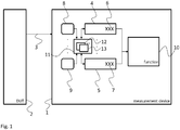
- Fig. 1 shows a measurement device 1, which measures at least one physical variable 3 of a device under test 2.
- the device under test 2 can e.g. be an electric circuit and the physical variable 3 can be e.g. a voltage or a current.
- the measurement circuit of the measurement device 1 is not explicitly shown. However, it is understood, that the measurement device 1 can comprise any type of adequate measurement circuits comprising elements like e.g. analog-to-digital converters, FPGAs and the like.
- the measurement circuit or measurement functions of the measurement device 1 are exemplarily shown as function 10. It is however clear, that the function 10 can be any configurable function in the measurement device 1. Possible other functions 10 can refer to the displaying of measured data or the like.
- the measurement device 1 comprises a plurality of parameter inputs 4, 5, two of which are shown in Fig. 1 . Further parameter inputs are hinted at by three dots.
- the parameter inputs 4, 5 serve for the user to input parameter values 6, 7 into the measurement device 1. These parameter values 6, 7 serve to configure the function 10. They can e.g. configure the time base or resolution of a measurement function 10 or the time base for displaying measured values or the like.
- the measurement device 1 comprises a plurality of function keys 8, 9, two of which are shown in Fig. 1 . Further function keys are hinted at by three dots. Even though the function keys 8, 9 are each shown next to one of the parameter inputs 4, 5 there is now direct coupling between the function keys 8, 9 and the parameter inputs 4, 5.
- the parameter inputs 4, 5 and the function keys 8, 9 are connected to a calculation unit 11, which comprises a plurality of calculation functions 12, 13, two of which are exemplarily shown.
- Every one of the function keys 8, 9 refers to one of the calculation functions 12, 13.
- the function keys 8, 9 can e.g. comprise an imprint of the respective function.
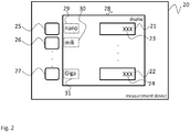
- An alternative is shown in Fig. 2 , where the respective function is variably displayed on display 28.
- the respective calculation function 12, 13 in the calculation unit 11 will then take one or more parameter values 6, 7 of the respective parameter input 4, 5 and input the result of the respective calculation function 12, 13 into the respective parameter input 4, 5 as new parameter value 6, 7. As already explained above, this parameter value 6, 7 can then be used by the function 10 as configuration parameter. If more than one parameter value 6, 7 are required for the respective calculation function 12, 13 the respective function key 8, 9 can be pushed between entering the respective parameter values 6, 7.
- the user can e.g. input "5" as parameter value 6, 7, "+” as function key 8, 9, and “3” as parameter value 6, 7.
- the calculation unit 11 will then perform an addition of 5 and 3 and provide 8 as the new parameter value 6, 7 in the respective parameter input 4, 5.
- the function key 8, 9 can e.g. be pushed after entering a plurality, i.e. two or more, of parameter values 6 or 7.
- the respective parameter input 4, 5, which the calculation unit 11 works on can e.g. be the last active parameter input 4, 5, i.e. where the last parameter value 6, 7 has been entered.
- dedicated select buttons can be provided, to select the respective parameter input 4, 5.
- Possible calculation functions 12, 13 can e.g. comprise adding, subtracting, multiplying or dividing at least two parameter values 6, 7. In addition, more complex calculation functions 12, 13 can be provided.
- a possible calculation function 12, 13 can e.g. calculate the ratio of a voltage divider, if two resistance values are given.
- Another possible calculation function 12, 13 can e.g. calculate the reciprocal value of a provided parameter value 6, 7.
- Another possible calculation function 12, 13 can comprise incrementing or decrementing the value of a parameter value 6, 7 by a predetermined number, e.g. 1, 2, 3 or any other number.
- Another possible calculation function 12, 13 can comprise multiplying the value of a parameter value 6, 7 by 10 elevated by a predetermined exponent, like e.g. 12, 9, 3, -3, -9, -12.
- the measurement device 20 of Fig. 2 comprises a plurality of function keys 25, 26, 27, which are arranged left of a display 28.
- the parameter inputs 21, 22 with the parameter values 23, 24 are displayed on the display 28. That means that they are drawn by graphics functions on the display 28 as opposed to providing separate displays, like e.g. alphanumeric displays.
- Fig. 2 allows easily changing the calculation function 12, 13 a function key 25, 26, 27 refers to.
- the functions can e.g. be changed depending on the context of the information displayed on the display 28 or of the respective measurement function 10, which is selected by a user.
- the function keys 25, 26, 27 can therefore also be called "context sensitive" function keys 25, 26, 27.
- Fig. 3 schematically shows a possible housing 40 for a measurement device 1, 20, which carries a detachable input device 41. That means that the input device 41 can be detached from the housing 40 and e.g. be placed by a user on a table, while providing inputs via the input device 41.
- the arrangement of keys and function keys 42, 43 on the detachable input device 41 is just exemplarily and can be used with any other embodiment of measurement devices 1, 20. Further, other key arrangements can be provided on the detachable input device 41. For sake of simplicity, only the first and the last keys 42, 43 are provided with a reference sign.
- the detachable input device 41 comprises five columns of keys with six keys each, wherein the fifth keys of the first and second column and the fifth keys of the fourth and fifth column, respectively, form a double sized key.
- Fig. 4 shows a block diagram of a configuration method for a measurement device 1, 20 for measuring a number of physical variables 3.
- the method comprises receiving S1 parameter values 6, 7, 23, 24, which configure at least one function 10 of the measurement device 1, 20 via a number of parameter inputs 4, 5, 21, 22. Further a number of function keys 8, 9, 25, 26, 27, 42, 43 is read S2, wherein every function key 8, 9, 25, 26, 27, 42, 43 refers to a predetermined calculation function 12, 13,
- the respective calculation function 12, 13 of a plurality of calculation functions 12, 13 is performed S3, with at least one parameter value 6, 7, 23, 24 provided in the one of the parameter inputs 4, 5, 21, 22. Further, the parameter value 6, 7, 23, 24 in the respective parameter input 4, 5, 21, 22 is replaced with the result of the calculation functions 12, 13.
- Possible calculation functions 12, 13 can e.g. comprise adding, subtracting, multiplying or dividing at least two parameter values 6, 7, 23, 24. In addition, more complex calculation functions 12, 13 can be provided.
- a possible calculation function 12, 13 can e.g. calculate the ratio of a voltage divider, if two resistance values are given.
- Another possible calculation function 12, 13 can e.g. calculate the reciprocal value of a provided parameter value 6, 7, 23, 24.
- Another possible calculation function 12, 13 can comprise incrementing or decrementing the value of a parameter value 6, 7, 23, 24 by a predetermined number, e.g. 1, 2, 3 or any other number.
- Another possible calculation function 12, 13 can comprise multiplying the value of a parameter value 6, 7, 23, 24 by 10 elevated by a predetermined exponent, like e.g. 12, 9, 3, -3, -9, -12.
- the method can further comprise arranging on a display 28 next to the function keys 8, 9, 25, 26, 27, 42, 43 adjacent for every function key 8, 9, 25, 26, 27, 42, 43 an indication 29, 30, 31 of the respective calculation function 12, 13.
Landscapes
- Physics & Mathematics (AREA)
- General Physics & Mathematics (AREA)
- Engineering & Computer Science (AREA)
- General Engineering & Computer Science (AREA)
- Theoretical Computer Science (AREA)
- Mathematical Analysis (AREA)
- Pure & Applied Mathematics (AREA)
- Computational Mathematics (AREA)
- Human Computer Interaction (AREA)
- Mathematical Optimization (AREA)
- Computing Systems (AREA)
- Microelectronics & Electronic Packaging (AREA)
- Computer Hardware Design (AREA)
- Quality & Reliability (AREA)
- Measuring Instrument Details And Bridges, And Automatic Balancing Devices (AREA)
- Testing Or Calibration Of Command Recording Devices (AREA)
Abstract
Description
- The present invention relates to a measurement device. The present invention further relates to a configuration method for such a measurement device.
- Although applicable in principal to any electronic device with user input, the present invention and its underlying problem will be hereinafter described in combination with test and measurement devices, such as oscilloscopes and network analyzers.
- In modern oscilloscopes a plurality of different parameters can be set by a user e.g. for recording and displaying measurement values. Usually, one parameter field is provided for each one of the single parameters, which can be set by the user. One single parameter value is provided by the user in the respective parameter field. This single value is used e.g. by a signal processing unit or control unit of the oscilloscope to configure e.g. the measurement process or the displaying of measured values.
- Against this background, the problem addressed by the present invention is a need for simplifying the parametrization of oscilloscopes.
- The present invention solves this object by a measurement device having the features of
independent claim 1 and/or by a configuration method having the features ofindependent claim 11. - Accordingly it is provided:
- A measurement device for measuring a number, i.e. one or more, of physical, e.g. electrical, variables comprises a number, i.e. one or more, of parameter inputs, wherein the parameter inputs are configured to receive parameter values, which configure at least one function, e.g. a measurement function or results displaying function, of the measurement device, a calculation unit, e.g. a calculation processor, which controllably performs calculation functions with at least one parameter value provided in a respective parameter input and replaces the parameter value in the respective parameter input with the result of the calculation, and a number, i.e. one or more, of function keys, wherein every function key controls the calculation unit to perform a predetermined one of the calculation functions, e.g. when the respective function key is actuated by a user.
- A configuration method for a measurement device for measuring a number of physical variables comprises receiving parameter values, which configure at least one function of the measurement device, via a number of parameter inputs, reading a number of function keys, wherein every function key refers to a predetermined calculation function, based on the readings of the function keys performing the respective calculation function of a plurality of calculation functions with at least one parameter value provided in a respective one of the parameter inputs, and replacing the parameter value in the respective parameter input with the result of the calculation.
- Modern measurement devices can comprise a plurality of measurement inputs and perform a plurality of complex measurement tasks on a plurality of different physical variables at the same time. Such a measurement device can e.g. be an oscilloscope or a network tester, which measures a plurality of voltages or currents in a complex electrical circuit.
- Usually, a user can configure certain parameters in the measurement device, like e.g. the voltage range of measured voltages or the voltage range of a diagram, which shows the measured values. The parameters, which are set by the user, are then used by the measurement device, e.g. by a controller in the measurement device, to configure the measuring hardware or the display. The controller can e.g. configure amplifiers, analog-to-digital converters, timers, display functions and the like.
- In some measurement devices, such parameters can be set once for all measurement inputs. In other devices, such parameters can be set individually for every measurement input.
- However, independently of the number of measurement inputs, the user must know the respective values he has to input into the parameter inputs. In case that e.g. just a single voltage, which ranges from 0 V to 5 V is measured, this parameter can easily be identified by the user.
- In complex electrical circuits, electrical elements like e.g. amplifiers, multipliers, dividers and the like modify the voltages throughout the electrical circuit. This makes it difficult for the user to determine the correct values for the respective parameter inputs, which define or parametrize measurements at nodes of such complex electrical circuits.
- The present invention therefore provides the user with a tool that allows him to derive functionally the correct values for the parameter inputs with the help of the calculation unit.
- The calculation unit will e.g. take values, which are sequentially provided by the user to one parameter input. The user can select a respective calculation function by use of the function keys, which is then performed with the values by the calculation unit. In one operation mode, the calculation unit will receive a first value via the respective parameter input, then a selection of a calculation function, and then a second value. As an alternative, in a second operation mode, the user can input a plurality of values into a parameter input and then select via a function key a calculation function, which is to be performed on the received values.
- The calculation unit then inputs the result of the calculation into the parameter input. This also implies that the result of the calculation is used as a parameter for configuring the measurement device.
- The parameter inputs can either be separate physical inputs, which are physically selected or activated, e.g. by respective push buttons and comprise a single alphanumeric display. As an alternative, the physical inputs can e.g. be parameter inputs, which are displayed as input fields on a graphical display of the measurement device. The respective parameter inputs can still be activated by push buttons. However, activation via a touch sensitive display is also possible. Any other type of input is also possible. The single values for the parameter inputs can e.g. be provided via a keyboard, e.g. via a standard PC keyboard or via a specific keyboard, which comprises numbers, comma, dot, and function keys. The display of the respective keys on a touch screen is also possible.
- Based on the finding of the present invention, the user can therefore mathematically model the functions in the electric circuit to be measured and automatically determine the correct parameter values. This greatly simplifies the identification of the correct parameter values for the user.
- Further embodiments of the present invention are subject of the further subclaims and of the following description, referring to the drawings.
- In one embodiment, one of the calculation functions can comprise adding or subtracting at least two parameter values. This e.g. allows automatically calculating value ranges for physical variables, which additively or subtractively overlay each other. If for example, the user wants to display voltages, which additively overlay each other, the user can simply input the maximum values of the voltages and select the sum function. While this may be a simple calculation if only two integer values or whole-number values have to be added, this calculation becomes more complex with the number of voltages and if e.g. decimal numbers are present. The present invention therefore takes the burden of the user to pre-calculate the respective parameter values.
- In one embodiment, one of the calculation functions can comprise multiplying or dividing at least two parameter values. This e.g. allows automatically calculating value ranges for physical variables, which starting from a base voltage value are e.g. amplified or attenuated. The user may e.g. want to measure a voltage in an electrical circuit, which is generated by a complex network of voltage amplifiers and voltage dividers. In this case, the user does not have to calculate the resulting voltage range manually but can simply model the complex network of voltage amplifiers and voltage dividers by performing the respective calculations in the parameter input. The amplifiers can e.g. be modeled by a multiplication with the respective amplification factor and the voltage dividers by a division by the respective division factor. The same applies to attenuators and the respective attenuation factor.
- In one embodiment, one of the calculation functions comprises calculating the ratio of a voltage divider formed by two resistances. The user can e.g. provide the values of resistances via the respective parameter input. This allows the user to calculate e.g. voltage ranges for measuring or displaying a voltage, which is generated by a voltage divider, individually. The calculation unit can e.g. calculate the ratio of the voltage divider and multiply the input voltage value by the respective ratio to determine the voltage range for the respective measurement task.
- In one embodiment, one of the calculation functions can comprise calculating the reciprocal value of a parameter value in a parameter input. This provides the user with a simple method of converting e.g. a frequency into a period or vice versa.
- In one embodiment, one of the calculation functions can comprise incrementing or decrementing the value of a parameter value in a parameter input by a predetermined number. The predetermined number can e.g. be configured in a settings menu of the measurement device. In one embodiment, the predetermined number can e.g. be one.
- In one embodiment, one of the calculation functions can comprise multiplying the value of a parameter value in a parameter input by 10 elevated by a predetermined exponent. The Exponent can e.g. be 3, 9, 12, -3, -9, -12 or any other number. Multiple function keys can be provided for different exponents. By specifically choosing the exponent, the scale of the respective parameter value can e.g. be adapted with the push of a single function key to the SI scales kilo (exponent 3), Mega (exponent 6), Giga (exponent 9), mili (exponent -3), mikro (exponent -6), nano (exponent -9), and pico (exponent - 12). This saves the user the inputting of a plurality of trailing of prefixing zeros.
- In one embodiment, the measurement device can comprise a display, wherein the function keys are arrange adjacent to the display and the display shows for every function key the respective calculation function. A display can controllably change its contents. Therefore, the displayed calculation functions can also be changed. The single function keys can therefore be individually configured to trigger different calculation functions, and the respective function can be displayed to the user.
- In one embodiment, the measurement device can comprise a housing and a detachable input device, which is detachably coupled to the housing, wherein the function keys are provided on the detachable input device. The detachable input device can e.g. be coupled to the rest of the measurement device via a cable or wirelessly. This allows freely positioning the detachable input device. The input device can also carry e.g. number keys, and further function keys, like e.g. an enter key for ending an input or arrows keys for navigating the different parameter inputs.
- For a more complete understanding of the present invention and advantages thereof, reference is now made to the following description taken in conjunction with the accompanying drawings. The invention is explained in more detail below using exemplary embodiments, which are specified in the schematic figures of the drawings, in which:
- Fig. 1
- shows a block diagram of an embodiment of a measurement device according to the present invention;
- Fig. 2
- shows a block diagram of another embodiment of a measurement device according to the present invention;
- Fig. 3
- shows a block diagram of an embodiment of a housing of a measurement device according to the present invention; and
- Fig. 4
- shows a block diagram of an embodiment of a method according to the present invention.
- The appended drawings are intended to provide further understanding of the embodiments of the invention. They illustrate embodiments and, in conjunction with the description, help to explain principles and concepts of the invention. Other embodiments and many of the advantages mentioned become apparent in view of the drawings. The elements in the drawings are not necessarily shown to scale.
- In the drawings, like, functionally equivalent and identically operating elements, features and components are provided with like reference signs in each case, unless stated otherwise.
-
Fig. 1 shows ameasurement device 1, which measures at least onephysical variable 3 of a device undertest 2. The device undertest 2 can e.g. be an electric circuit and thephysical variable 3 can be e.g. a voltage or a current. - The measurement circuit of the
measurement device 1 is not explicitly shown. However, it is understood, that themeasurement device 1 can comprise any type of adequate measurement circuits comprising elements like e.g. analog-to-digital converters, FPGAs and the like. The measurement circuit or measurement functions of themeasurement device 1 are exemplarily shown asfunction 10. It is however clear, that thefunction 10 can be any configurable function in themeasurement device 1. Possibleother functions 10 can refer to the displaying of measured data or the like. - The
measurement device 1 comprises a plurality ofparameter inputs Fig. 1 . Further parameter inputs are hinted at by three dots. Theparameter inputs parameter values measurement device 1. These parameter values 6, 7 serve to configure thefunction 10. They can e.g. configure the time base or resolution of ameasurement function 10 or the time base for displaying measured values or the like. - Further, the
measurement device 1 comprises a plurality offunction keys Fig. 1 . Further function keys are hinted at by three dots. Even though thefunction keys parameter inputs function keys parameter inputs - Rather, the
parameter inputs function keys calculation unit 11, which comprises a plurality of calculation functions 12, 13, two of which are exemplarily shown. - Every one of the
function keys function keys Fig. 2 , where the respective function is variably displayed ondisplay 28. - If the user pushes one of the
function keys respective calculation function calculation unit 11. Thecalculation unit 11 will then take one ormore parameter values respective parameter input respective calculation function respective parameter input new parameter value parameter value function 10 as configuration parameter. If more than oneparameter value respective calculation function respective function key respective parameter values - Just exemplarily, the user can e.g. input "5" as
parameter value function key parameter value calculation unit 11 will then perform an addition of 5 and 3 and provide 8 as thenew parameter value respective parameter input function key parameter values - The
respective parameter input calculation unit 11 works on can e.g. be the lastactive parameter input last parameter value respective parameter input - Possible calculation functions 12, 13 can e.g. comprise adding, subtracting, multiplying or dividing at least two
parameter values possible calculation function possible calculation function parameter value possible calculation function parameter value possible calculation function parameter value - The
measurement device 20 ofFig. 2 comprises a plurality offunction keys display 28. Theparameter inputs display 28. That means that they are drawn by graphics functions on thedisplay 28 as opposed to providing separate displays, like e.g. alphanumeric displays. In addition, on thedisplay 28 anindication respective calculation function 12, 13 afunction key respective function key indication respective calculation function parameter inputs display 28, e.g. with discrete parameter inputs. - The arrangement of
Fig. 2 allows easily changing thecalculation function 12, 13 afunction key display 28 or of therespective measurement function 10, which is selected by a user. Thefunction keys function keys -
Fig. 3 schematically shows apossible housing 40 for ameasurement device detachable input device 41. That means that theinput device 41 can be detached from thehousing 40 and e.g. be placed by a user on a table, while providing inputs via theinput device 41. - The arrangement of keys and
function keys detachable input device 41 is just exemplarily and can be used with any other embodiment ofmeasurement devices detachable input device 41. For sake of simplicity, only the first and thelast keys - The
detachable input device 41 comprises five columns of keys with six keys each, wherein the fifth keys of the first and second column and the fifth keys of the fourth and fifth column, respectively, form a double sized key. - Besides number keys ranging from 0 to 9, the following function keys are provided on the detachable input device 41:
- p: pico -> multiply the respective value by 1/1000000000000 or 10^-12
- n: nano -> multiply the respective value by 1/1000000000 or 10^-9
- µ: mikro -> multiply the respective value by 1/1000000 or 10^-6
- m: mili -> multiply the respective value by 1/1000 or 10^-3
- k: kilo -> multiply the respective value by 1000 or 10^3
- M: Mega -> multiply the respective value by 1000000 or 10^6
- G: Giga -> multiply the respective value by 1000000000 or 10^9
- Exp -> provide an arbitrary exponent (x^y)
- Clear -> clear the respective parameter input.
- Enter -> finish entering a value in a parameter input
- 1/x -> calculate the reciprocal value for the respective parameter input
- +,-,*,/ -> perform the respective arithmetic operation
- ⇐ -> delete last input
-
Fig. 4 shows a block diagram of a configuration method for ameasurement device physical variables 3. - The method comprises receiving S1 parameter values 6, 7, 23, 24, which configure at least one
function 10 of themeasurement device parameter inputs function keys function key predetermined calculation function - Based on the readings of the
function keys respective calculation function parameter value parameter inputs parameter value respective parameter input - Possible calculation functions 12, 13 can e.g. comprise adding, subtracting, multiplying or dividing at least two
parameter values possible calculation function possible calculation function parameter value possible calculation function parameter value possible calculation function parameter value - The method can further comprise arranging on a
display 28 next to thefunction keys function key indication respective calculation function - Although specific embodiments have been illustrated and described herein, it will be appreciated by those of ordinary skill in the art that a variety of alternate and/or equivalent implementations exist. It should be appreciated that the exemplary embodiment or exemplary embodiments are only examples, and are not intended to limit the scope, applicability, or configuration in any way. Rather, the foregoing summary and detailed description will provide those skilled in the art with a convenient road map for implementing at least one exemplary embodiment, it being understood that various changes may be made in the function and arrangement of elements described in an exemplary embodiment without departing from the scope as set forth in the appended claims and their legal equivalents. Generally, this application is intended to cover any adaptations or variations of the specific embodiments discussed herein.
- In the foregoing detailed description, various features are grouped together in one or more examples or examples for the purpose of streamlining the disclosure. It is understood that the above description is intended to be illustrative, and not restrictive. It is intended to cover all alternatives, modifications and equivalents as may be included within the scope of the invention. Many other examples will be apparent to one skilled in the art upon reviewing the above specification.
- Specific nomenclature used in the foregoing specification is used to provide a thorough understanding of the invention. However, it will be apparent to one skilled in the art in light of the specification provided herein that the specific details are not required in order to practice the invention. Thus, the foregoing descriptions of specific embodiments of the present invention are presented for purposes of illustration and description. They are not intended to be exhaustive or to limit the invention to the precise forms disclosed; obviously many modifications and variations are possible in view of the above teachings. The embodiments were chosen and described in order to best explain the principles of the invention and its practical applications, to thereby enable others skilled in the art to best utilize the invention and various embodiments with various modifications as are suited to the particular use contemplated. Throughout the specification, the terms "including" and "in which" are used as the plain-English equivalents of the respective terms "comprising" and "wherein," respectively. Moreover, the terms "first," "second," and "third," etc., are used merely as labels, and are not intended to impose numerical requirements on or to establish a certain ranking of importance of their objects.
-
- 1
- measurement device
- 2
- device under test
- 3
- physical variable
- 4
- parameter input
- 5
- parameter input
- 6
- parameter value
- 7
- parameter value
- 8
- function key
- 9
- function key
- 10
- function
- 11
- calculation unit
- 12
- calculation function
- 13
- calculation function
- 20
- measurement device
- 21
- parameter input
- 22
- parameter input
- 23
- parameter value
- 24
- parameter value
- 25
- function key
- 26
- function key
- 27
- function key
- 28
- display
- 29
- indication
- 30
- indication
- 31
- indication
- 40
- housing
- 41
- detachable input device
- 42
- function key
- 43
- function key
Claims (15)
- Measurement device for measuring a number of physical variables, the measurement device comprising:a number of parameter inputs, wherein the parameter inputs are configured to receive parameter values, which configure at least one function of the measurement device,a calculation unit, which controllably performs calculation functions with at least one parameter value provided in a respective parameter input and replaces the parameter value in the respective parameter input with the result of the calculation, anda number of function keys, wherein every function key controls the calculation unit to perform a predetermined one of the calculation functions.
- Measurement device according to claim 1, wherein one of the calculation functions comprises adding or subtracting at least two parameter values.
- Measurement device according to any of the preceding claims, wherein one of the calculation functions comprises multiplying or dividing at least two parameter values.
- Measurement device according to any of the preceding claims, wherein one of the calculation functions comprises calculating the ratio of a voltage divider formed by two resistances.
- Measurement device according to any of the preceding claims, wherein one of the calculation functions comprises calculating the reciprocal value of a parameter value in a parameter input.
- Measurement device according to any of the preceding claims, wherein one of the calculation functions comprises incrementing the value of a parameter value in a parameter input by a predetermined number.
- Measurement device according to any of the preceding claims, wherein one of the calculation functions comprises decrementing the value of a parameter value in a parameter input by a predetermined number.
- Measurement device according to any of the preceding claims, wherein one of the calculation functions comprises multiplying the value of a parameter value in a parameter input by 10 elevated by a predetermined exponent.
- Measurement device according to any of the preceding claims, further comprising a display, wherein the function keys are arrange adjacent to the display and the display shows for every function key an indication of the respective calculation function.
- Measurement device according to any of the preceding claims, further comprising a housing and a detachable input device, which is detachably coupled to the housing, wherein the function keys are provided on the detachable input device.
- Configuration method for a measurement device for measuring a number of physical variables, in particular a measuring device according to any of the claims 1 to 10, the method comprising:receiving (S1) parameter values, which configure at least one function of the measurement device, via a number of parameter inputs,reading (S2) a number of function keys, wherein every function key refers to a predetermined calculation function,based on the readings of the function keys performing (S3) the respective calculation function of a plurality of calculation functions with at least one parameter value provided in a respective one of the parameter inputs, andreplacing (S4) the parameter value in the respective parameter input with the result of the calculation.
- Configuration method according to claim 11, wherein one of the calculation functions comprises adding or subtracting at least two parameter value.
- Configuration method according to claim 11, wherein one of the calculation functions comprises multiplying or dividing at least two parameter values.
- Configuration method according to any of the preceding method claims, wherein one of the calculation functions comprises:calculating the ratio of a voltage divider formed by two resistances, and/orcalculating the reciprocal value of a parameter value in a parameter input, and/orincrementing the value of a parameter value in a parameter input by a predetermined number, and/ordecrementing the value of a parameter value in a parameter input by a predetermined number, and/ormultiplying the value of a parameter value in a parameter input by 10 elevated by a predetermined exponent.
- Configuration method according to any of the preceding method claims, further comprising the step of arranging on a display next to the function keys adjacent for every function key an indication of the respective calculation function.
Applications Claiming Priority (1)
| Application Number | Priority Date | Filing Date | Title |
|---|---|---|---|
| US15/282,573 US10908197B2 (en) | 2016-09-30 | 2016-09-30 | Measurement device and configuration method |
Publications (2)
| Publication Number | Publication Date |
|---|---|
| EP3301459A1 true EP3301459A1 (en) | 2018-04-04 |
| EP3301459B1 EP3301459B1 (en) | 2021-03-31 |
Family
ID=57868077
Family Applications (1)
| Application Number | Title | Priority Date | Filing Date |
|---|---|---|---|
| EP17152321.0A Active EP3301459B1 (en) | 2016-09-30 | 2017-01-20 | Measurement device and configuration method |
Country Status (3)
| Country | Link |
|---|---|
| US (1) | US10908197B2 (en) |
| EP (1) | EP3301459B1 (en) |
| CN (1) | CN107883988B (en) |
Citations (2)
| Publication number | Priority date | Publication date | Assignee | Title |
|---|---|---|---|---|
| US4072851A (en) * | 1976-03-26 | 1978-02-07 | Norland Corporation | Waveform measuring instrument with resident programmed processor for controlled waveform display and waveform data reduction and calculation |
| US5081592A (en) * | 1987-08-05 | 1992-01-14 | Tektronix, Inc. | Test system for acquiring, calculating and displaying representations of data sequences |
Family Cites Families (14)
| Publication number | Priority date | Publication date | Assignee | Title |
|---|---|---|---|---|
| US2244369A (en) * | 1938-10-31 | 1941-06-03 | Rca Corp | Electrical measuring and calculating device |
| US3582955A (en) * | 1969-09-24 | 1971-06-01 | James A Mcmurray | Oscilloscope display for plotting device |
| GB8912643D0 (en) | 1989-06-02 | 1989-07-19 | Solar Wide Ind Ltd | Distance measurement device |
| US5162723A (en) | 1991-02-11 | 1992-11-10 | Hewlett-Packard Company | Sampling signal analyzer |
| JP2000146629A (en) * | 1998-09-23 | 2000-05-26 | Agilent Technol Inc | Help screen information display device for measuring devices |
| US6937237B2 (en) * | 2001-02-28 | 2005-08-30 | Agilent Technologies, Inc. | Sorting data based on data attributes for display in multiple display windows |
| DE10130943A1 (en) | 2001-05-18 | 2002-11-21 | Rohde & Schwarz | Signal generator has baseband unit, in-quadrature modulator and optical display device that displays digital baseband signal stored in memory in predefined display format |
| CN1265281C (en) * | 2002-07-29 | 2006-07-19 | 矽统科技股份有限公司 | Logarithm operation method and device for floating point numbers |
| US8773108B2 (en) * | 2009-11-10 | 2014-07-08 | Power Monitors, Inc. | System, method, and apparatus for a safe powerline communications instrumentation front-end |
| CN201637778U (en) * | 2010-04-16 | 2010-11-17 | 浙江容大电力设备制造有限公司 | A power factor sampling and compensation equipment |
| US9081043B2 (en) * | 2012-02-10 | 2015-07-14 | Sharp Laboratories Of America, Inc. | System and method for calculating power using contactless voltage waveform shape sensor |
| CN104236519B (en) | 2014-09-22 | 2017-09-22 | 浙江荣胜工具有限公司 | Three-dimensional perspective measurement apparatus |
| JP6862621B2 (en) * | 2015-12-21 | 2021-04-21 | アンリツ株式会社 | Measuring device and measuring method |
| CN106452389B (en) * | 2016-09-30 | 2018-10-26 | 中国人民解放军63908部队 | Based on index recycle window temporal modulation filter design method and filter |
-
2016
- 2016-09-30 US US15/282,573 patent/US10908197B2/en active Active
-
2017
- 2017-01-20 EP EP17152321.0A patent/EP3301459B1/en active Active
- 2017-03-29 CN CN201710197788.3A patent/CN107883988B/en active Active
Patent Citations (2)
| Publication number | Priority date | Publication date | Assignee | Title |
|---|---|---|---|---|
| US4072851A (en) * | 1976-03-26 | 1978-02-07 | Norland Corporation | Waveform measuring instrument with resident programmed processor for controlled waveform display and waveform data reduction and calculation |
| US5081592A (en) * | 1987-08-05 | 1992-01-14 | Tektronix, Inc. | Test system for acquiring, calculating and displaying representations of data sequences |
Non-Patent Citations (2)
| Title |
|---|
| ERIK SCHMIDT: "CBL Made Easy! 5 Steps to Getting Started with the CBL System, Vernier Sensors, and Texas Instruments Graphing Calculators", 3 May 2004 (2004-05-03), 13979 SW Millikan Way Beaverton, Oregon, USA, pages 1 - 22, XP055352259, Retrieved from the Internet <URL:http://www2.vernier.com/free/CBL-Easy.pdf> [retrieved on 20170307] * |
| HEINZ-DIETER HINKELMANN: "Introduction to the Practical Use of the CBL an CBR in Physics", PROCEEDINGS OF THE THIRD INTERNATIONAL DERIVE/TI-92 CONFERENCE, 14 July 1998 (1998-07-14), Gettysburg, Pennsylvania, USA, pages 1 - 17, XP055352274, Retrieved from the Internet <URL:http://www.cs.gettysburg.edu/~leinbach/DRVTI_Conf/Hinkleman.PDF> [retrieved on 20170307] * |
Also Published As
| Publication number | Publication date |
|---|---|
| US10908197B2 (en) | 2021-02-02 |
| EP3301459B1 (en) | 2021-03-31 |
| US20180095116A1 (en) | 2018-04-05 |
| CN107883988A (en) | 2018-04-06 |
| CN107883988B (en) | 2022-04-19 |
Similar Documents
| Publication | Publication Date | Title |
|---|---|---|
| EP3011901B1 (en) | Apparatus for measuring body fat and method thereof | |
| Lira et al. | Comparison between the conventional and Bayesian approaches to evaluate measurement data | |
| CN114121140A (en) | Chip testing method, system, electronic device and storage medium | |
| CN112817509B (en) | Display of electronic measuring device and method for changing the value of electronic measuring device | |
| JP2023030085A (en) | Information processing device, controlling method, and program | |
| CN117075780A (en) | Signal analysis interactive method, device, electronic equipment and storage medium | |
| CN103970406A (en) | Method For Automatically Adjusting The Magnification And Offset Of A Display To View A Selected Feature | |
| US10908197B2 (en) | Measurement device and configuration method | |
| JP2014203095A (en) | Information processor, and information processing method and program | |
| CN112739999B (en) | Fractional mirror ratio technology for digital remote temperature sensors and related systems, methods and devices | |
| CN114064637B (en) | Visual processing method, device, equipment and medium for pivot table | |
| US20090248358A1 (en) | Real Time Operation Specification Calculation System That Provides Specifications To A User Interface | |
| WO2020075436A1 (en) | Predictive situation visualization device, predictive situation visualization method and predictive situation visualization program | |
| US20250216427A1 (en) | Measurement application device | |
| EP3822761A1 (en) | Display for an electronic measurement device | |
| JP5440044B2 (en) | Waveform display device | |
| Mangelsdorf | Accuracy or affectation: Are there too many digits in your work?[Shop Talk: What you didn’t Learn in School] | |
| CN116430095B (en) | Alternating current measurement methods, apparatus, systems and computer-readable storage media | |
| US20250337429A1 (en) | Measurement application device and method | |
| JP4090574B2 (en) | measuring device | |
| JP5797056B2 (en) | Equivalent circuit analysis apparatus and equivalent circuit analysis method | |
| EP4506695A1 (en) | Measurement application device, method, and computer program product | |
| US20250355677A1 (en) | Method and configuration system | |
| JP5717344B2 (en) | Measuring apparatus and measuring method | |
| JP2014163931A (en) | Measurement control device |
Legal Events
| Date | Code | Title | Description |
|---|---|---|---|
| PUAI | Public reference made under article 153(3) epc to a published international application that has entered the european phase |
Free format text: ORIGINAL CODE: 0009012 |
|
| STAA | Information on the status of an ep patent application or granted ep patent |
Free format text: STATUS: THE APPLICATION HAS BEEN PUBLISHED |
|
| AK | Designated contracting states |
Kind code of ref document: A1 Designated state(s): AL AT BE BG CH CY CZ DE DK EE ES FI FR GB GR HR HU IE IS IT LI LT LU LV MC MK MT NL NO PL PT RO RS SE SI SK SM TR |
|
| AX | Request for extension of the european patent |
Extension state: BA ME |
|
| STAA | Information on the status of an ep patent application or granted ep patent |
Free format text: STATUS: REQUEST FOR EXAMINATION WAS MADE |
|
| 17P | Request for examination filed |
Effective date: 20180928 |
|
| RBV | Designated contracting states (corrected) |
Designated state(s): AL AT BE BG CH CY CZ DE DK EE ES FI FR GB GR HR HU IE IS IT LI LT LU LV MC MK MT NL NO PL PT RO RS SE SI SK SM TR |
|
| STAA | Information on the status of an ep patent application or granted ep patent |
Free format text: STATUS: EXAMINATION IS IN PROGRESS |
|
| 17Q | First examination report despatched |
Effective date: 20200227 |
|
| GRAP | Despatch of communication of intention to grant a patent |
Free format text: ORIGINAL CODE: EPIDOSNIGR1 |
|
| STAA | Information on the status of an ep patent application or granted ep patent |
Free format text: STATUS: GRANT OF PATENT IS INTENDED |
|
| INTG | Intention to grant announced |
Effective date: 20201117 |
|
| GRAS | Grant fee paid |
Free format text: ORIGINAL CODE: EPIDOSNIGR3 |
|
| GRAA | (expected) grant |
Free format text: ORIGINAL CODE: 0009210 |
|
| STAA | Information on the status of an ep patent application or granted ep patent |
Free format text: STATUS: THE PATENT HAS BEEN GRANTED |
|
| AK | Designated contracting states |
Kind code of ref document: B1 Designated state(s): AL AT BE BG CY CZ DE DK EE ES FI FR GB GR HR HU IS IT LT LU LV MC MK MT NL NO PL PT RO RS SE SI SK SM TR |
|
| RBV | Designated contracting states (corrected) |
Designated state(s): AL AT BE BG CY CZ DE DK EE ES FI FR GB GR HR HU IS IT LT LU LV MC MK MT NL NO PL PT RO RS SE SI SK SM TR |
|
| REG | Reference to a national code |
Ref country code: GB Ref legal event code: FG4D |
|
| REG | Reference to a national code |
Ref country code: DE Ref legal event code: R096 Ref document number: 602017035508 Country of ref document: DE Ref country code: AT Ref legal event code: REF Ref document number: 1377537 Country of ref document: AT Kind code of ref document: T Effective date: 20210415 |
|
| REG | Reference to a national code |
Ref country code: LT Ref legal event code: MG9D |
|
| PG25 | Lapsed in a contracting state [announced via postgrant information from national office to epo] |
Ref country code: HR Free format text: LAPSE BECAUSE OF FAILURE TO SUBMIT A TRANSLATION OF THE DESCRIPTION OR TO PAY THE FEE WITHIN THE PRESCRIBED TIME-LIMIT Effective date: 20210331 Ref country code: FI Free format text: LAPSE BECAUSE OF FAILURE TO SUBMIT A TRANSLATION OF THE DESCRIPTION OR TO PAY THE FEE WITHIN THE PRESCRIBED TIME-LIMIT Effective date: 20210331 Ref country code: NO Free format text: LAPSE BECAUSE OF FAILURE TO SUBMIT A TRANSLATION OF THE DESCRIPTION OR TO PAY THE FEE WITHIN THE PRESCRIBED TIME-LIMIT Effective date: 20210630 Ref country code: BG Free format text: LAPSE BECAUSE OF FAILURE TO SUBMIT A TRANSLATION OF THE DESCRIPTION OR TO PAY THE FEE WITHIN THE PRESCRIBED TIME-LIMIT Effective date: 20210630 |
|
| PG25 | Lapsed in a contracting state [announced via postgrant information from national office to epo] |
Ref country code: SE Free format text: LAPSE BECAUSE OF FAILURE TO SUBMIT A TRANSLATION OF THE DESCRIPTION OR TO PAY THE FEE WITHIN THE PRESCRIBED TIME-LIMIT Effective date: 20210331 Ref country code: LV Free format text: LAPSE BECAUSE OF FAILURE TO SUBMIT A TRANSLATION OF THE DESCRIPTION OR TO PAY THE FEE WITHIN THE PRESCRIBED TIME-LIMIT Effective date: 20210331 Ref country code: RS Free format text: LAPSE BECAUSE OF FAILURE TO SUBMIT A TRANSLATION OF THE DESCRIPTION OR TO PAY THE FEE WITHIN THE PRESCRIBED TIME-LIMIT Effective date: 20210331 |
|
| REG | Reference to a national code |
Ref country code: NL Ref legal event code: MP Effective date: 20210331 |
|
| REG | Reference to a national code |
Ref country code: AT Ref legal event code: MK05 Ref document number: 1377537 Country of ref document: AT Kind code of ref document: T Effective date: 20210331 |
|
| PG25 | Lapsed in a contracting state [announced via postgrant information from national office to epo] |
Ref country code: NL Free format text: LAPSE BECAUSE OF FAILURE TO SUBMIT A TRANSLATION OF THE DESCRIPTION OR TO PAY THE FEE WITHIN THE PRESCRIBED TIME-LIMIT Effective date: 20210331 Ref country code: SM Free format text: LAPSE BECAUSE OF FAILURE TO SUBMIT A TRANSLATION OF THE DESCRIPTION OR TO PAY THE FEE WITHIN THE PRESCRIBED TIME-LIMIT Effective date: 20210331 Ref country code: AT Free format text: LAPSE BECAUSE OF FAILURE TO SUBMIT A TRANSLATION OF THE DESCRIPTION OR TO PAY THE FEE WITHIN THE PRESCRIBED TIME-LIMIT Effective date: 20210331 Ref country code: EE Free format text: LAPSE BECAUSE OF FAILURE TO SUBMIT A TRANSLATION OF THE DESCRIPTION OR TO PAY THE FEE WITHIN THE PRESCRIBED TIME-LIMIT Effective date: 20210331 Ref country code: CZ Free format text: LAPSE BECAUSE OF FAILURE TO SUBMIT A TRANSLATION OF THE DESCRIPTION OR TO PAY THE FEE WITHIN THE PRESCRIBED TIME-LIMIT Effective date: 20210331 Ref country code: LT Free format text: LAPSE BECAUSE OF FAILURE TO SUBMIT A TRANSLATION OF THE DESCRIPTION OR TO PAY THE FEE WITHIN THE PRESCRIBED TIME-LIMIT Effective date: 20210331 |
|
| PG25 | Lapsed in a contracting state [announced via postgrant information from national office to epo] |
Ref country code: IS Free format text: LAPSE BECAUSE OF FAILURE TO SUBMIT A TRANSLATION OF THE DESCRIPTION OR TO PAY THE FEE WITHIN THE PRESCRIBED TIME-LIMIT Effective date: 20210731 Ref country code: PT Free format text: LAPSE BECAUSE OF FAILURE TO SUBMIT A TRANSLATION OF THE DESCRIPTION OR TO PAY THE FEE WITHIN THE PRESCRIBED TIME-LIMIT Effective date: 20210802 Ref country code: PL Free format text: LAPSE BECAUSE OF FAILURE TO SUBMIT A TRANSLATION OF THE DESCRIPTION OR TO PAY THE FEE WITHIN THE PRESCRIBED TIME-LIMIT Effective date: 20210331 Ref country code: RO Free format text: LAPSE BECAUSE OF FAILURE TO SUBMIT A TRANSLATION OF THE DESCRIPTION OR TO PAY THE FEE WITHIN THE PRESCRIBED TIME-LIMIT Effective date: 20210331 Ref country code: SK Free format text: LAPSE BECAUSE OF FAILURE TO SUBMIT A TRANSLATION OF THE DESCRIPTION OR TO PAY THE FEE WITHIN THE PRESCRIBED TIME-LIMIT Effective date: 20210331 |
|
| REG | Reference to a national code |
Ref country code: DE Ref legal event code: R097 Ref document number: 602017035508 Country of ref document: DE |
|
| PG25 | Lapsed in a contracting state [announced via postgrant information from national office to epo] |
Ref country code: ES Free format text: LAPSE BECAUSE OF FAILURE TO SUBMIT A TRANSLATION OF THE DESCRIPTION OR TO PAY THE FEE WITHIN THE PRESCRIBED TIME-LIMIT Effective date: 20210331 Ref country code: AL Free format text: LAPSE BECAUSE OF FAILURE TO SUBMIT A TRANSLATION OF THE DESCRIPTION OR TO PAY THE FEE WITHIN THE PRESCRIBED TIME-LIMIT Effective date: 20210331 Ref country code: DK Free format text: LAPSE BECAUSE OF FAILURE TO SUBMIT A TRANSLATION OF THE DESCRIPTION OR TO PAY THE FEE WITHIN THE PRESCRIBED TIME-LIMIT Effective date: 20210331 |
|
| PLBE | No opposition filed within time limit |
Free format text: ORIGINAL CODE: 0009261 |
|
| STAA | Information on the status of an ep patent application or granted ep patent |
Free format text: STATUS: NO OPPOSITION FILED WITHIN TIME LIMIT |
|
| 26N | No opposition filed |
Effective date: 20220104 |
|
| PG25 | Lapsed in a contracting state [announced via postgrant information from national office to epo] |
Ref country code: IS Free format text: LAPSE BECAUSE OF FAILURE TO SUBMIT A TRANSLATION OF THE DESCRIPTION OR TO PAY THE FEE WITHIN THE PRESCRIBED TIME-LIMIT Effective date: 20210731 |
|
| PG25 | Lapsed in a contracting state [announced via postgrant information from national office to epo] |
Ref country code: IT Free format text: LAPSE BECAUSE OF FAILURE TO SUBMIT A TRANSLATION OF THE DESCRIPTION OR TO PAY THE FEE WITHIN THE PRESCRIBED TIME-LIMIT Effective date: 20210331 |
|
| PG25 | Lapsed in a contracting state [announced via postgrant information from national office to epo] |
Ref country code: MC Free format text: LAPSE BECAUSE OF FAILURE TO SUBMIT A TRANSLATION OF THE DESCRIPTION OR TO PAY THE FEE WITHIN THE PRESCRIBED TIME-LIMIT Effective date: 20210331 |
|
| REG | Reference to a national code |
Ref country code: BE Ref legal event code: MM Effective date: 20220131 |
|
| PG25 | Lapsed in a contracting state [announced via postgrant information from national office to epo] |
Ref country code: LU Free format text: LAPSE BECAUSE OF NON-PAYMENT OF DUE FEES Effective date: 20220120 |
|
| PG25 | Lapsed in a contracting state [announced via postgrant information from national office to epo] |
Ref country code: BE Free format text: LAPSE BECAUSE OF NON-PAYMENT OF DUE FEES Effective date: 20220131 |
|
| P01 | Opt-out of the competence of the unified patent court (upc) registered |
Effective date: 20230525 |
|
| PG25 | Lapsed in a contracting state [announced via postgrant information from national office to epo] |
Ref country code: HU Free format text: LAPSE BECAUSE OF FAILURE TO SUBMIT A TRANSLATION OF THE DESCRIPTION OR TO PAY THE FEE WITHIN THE PRESCRIBED TIME-LIMIT; INVALID AB INITIO Effective date: 20170120 |
|
| PG25 | Lapsed in a contracting state [announced via postgrant information from national office to epo] |
Ref country code: MK Free format text: LAPSE BECAUSE OF FAILURE TO SUBMIT A TRANSLATION OF THE DESCRIPTION OR TO PAY THE FEE WITHIN THE PRESCRIBED TIME-LIMIT Effective date: 20210331 Ref country code: CY Free format text: LAPSE BECAUSE OF FAILURE TO SUBMIT A TRANSLATION OF THE DESCRIPTION OR TO PAY THE FEE WITHIN THE PRESCRIBED TIME-LIMIT Effective date: 20210331 |
|
| PG25 | Lapsed in a contracting state [announced via postgrant information from national office to epo] |
Ref country code: TR Free format text: LAPSE BECAUSE OF FAILURE TO SUBMIT A TRANSLATION OF THE DESCRIPTION OR TO PAY THE FEE WITHIN THE PRESCRIBED TIME-LIMIT Effective date: 20210331 |
|
| PG25 | Lapsed in a contracting state [announced via postgrant information from national office to epo] |
Ref country code: MT Free format text: LAPSE BECAUSE OF FAILURE TO SUBMIT A TRANSLATION OF THE DESCRIPTION OR TO PAY THE FEE WITHIN THE PRESCRIBED TIME-LIMIT Effective date: 20210331 |
|
| PG25 | Lapsed in a contracting state [announced via postgrant information from national office to epo] |
Ref country code: GR Free format text: LAPSE BECAUSE OF NON-PAYMENT OF DUE FEES Effective date: 20210331 |
|
| PG25 | Lapsed in a contracting state [announced via postgrant information from national office to epo] |
Ref country code: GR Free format text: LAPSE BECAUSE OF NON-PAYMENT OF DUE FEES Effective date: 20210331 |
|
| PGFP | Annual fee paid to national office [announced via postgrant information from national office to epo] |
Ref country code: GB Payment date: 20260122 Year of fee payment: 10 |
|
| PGFP | Annual fee paid to national office [announced via postgrant information from national office to epo] |
Ref country code: DE Payment date: 20260120 Year of fee payment: 10 |
|
| PGFP | Annual fee paid to national office [announced via postgrant information from national office to epo] |
Ref country code: FR Payment date: 20260127 Year of fee payment: 10 |