EP3301419B1 - Exhaust gas temperature sensing probe assembly - Google Patents
Exhaust gas temperature sensing probe assembly Download PDFInfo
- Publication number
- EP3301419B1 EP3301419B1 EP17193187.6A EP17193187A EP3301419B1 EP 3301419 B1 EP3301419 B1 EP 3301419B1 EP 17193187 A EP17193187 A EP 17193187A EP 3301419 B1 EP3301419 B1 EP 3301419B1
- Authority
- EP
- European Patent Office
- Prior art keywords
- temperature sensing
- sensing probe
- thermocouple junction
- probe assembly
- housing
- Prior art date
- Legal status (The legal status is an assumption and is not a legal conclusion. Google has not performed a legal analysis and makes no representation as to the accuracy of the status listed.)
- Active
Links
- 239000000523 sample Substances 0.000 title claims description 107
- 230000003247 decreasing effect Effects 0.000 claims 1
- 230000001419 dependent effect Effects 0.000 claims 1
- 239000007789 gas Substances 0.000 description 49
- 238000002485 combustion reaction Methods 0.000 description 6
- 230000000712 assembly Effects 0.000 description 5
- 238000000429 assembly Methods 0.000 description 5
- 230000004044 response Effects 0.000 description 5
- 238000009529 body temperature measurement Methods 0.000 description 4
- 230000008901 benefit Effects 0.000 description 3
- 238000010276 construction Methods 0.000 description 3
- 239000000446 fuel Substances 0.000 description 3
- 230000033001 locomotion Effects 0.000 description 3
- 230000008859 change Effects 0.000 description 2
- 125000004122 cyclic group Chemical group 0.000 description 2
- 238000013461 design Methods 0.000 description 2
- 239000012530 fluid Substances 0.000 description 2
- 230000006870 function Effects 0.000 description 2
- 239000000463 material Substances 0.000 description 2
- 238000000034 method Methods 0.000 description 2
- 238000012545 processing Methods 0.000 description 2
- 239000000956 alloy Substances 0.000 description 1
- 238000004891 communication Methods 0.000 description 1
- 238000010586 diagram Methods 0.000 description 1
- 230000000694 effects Effects 0.000 description 1
- 230000006872 improvement Effects 0.000 description 1
- 238000009434 installation Methods 0.000 description 1
- 238000005259 measurement Methods 0.000 description 1
- 229910052751 metal Inorganic materials 0.000 description 1
- 239000002184 metal Substances 0.000 description 1
- 229910001092 metal group alloy Inorganic materials 0.000 description 1
- 150000002739 metals Chemical class 0.000 description 1
- 239000000203 mixture Substances 0.000 description 1
- 238000010248 power generation Methods 0.000 description 1
- 230000009467 reduction Effects 0.000 description 1
- 230000007704 transition Effects 0.000 description 1
- 238000011144 upstream manufacturing Methods 0.000 description 1
Images


Classifications
-
- F—MECHANICAL ENGINEERING; LIGHTING; HEATING; WEAPONS; BLASTING
- F01—MACHINES OR ENGINES IN GENERAL; ENGINE PLANTS IN GENERAL; STEAM ENGINES
- F01D—NON-POSITIVE DISPLACEMENT MACHINES OR ENGINES, e.g. STEAM TURBINES
- F01D17/00—Regulating or controlling by varying flow
- F01D17/02—Arrangement of sensing elements
- F01D17/08—Arrangement of sensing elements responsive to condition of working-fluid, e.g. pressure
- F01D17/085—Arrangement of sensing elements responsive to condition of working-fluid, e.g. pressure to temperature
-
- G—PHYSICS
- G01—MEASURING; TESTING
- G01K—MEASURING TEMPERATURE; MEASURING QUANTITY OF HEAT; THERMALLY-SENSITIVE ELEMENTS NOT OTHERWISE PROVIDED FOR
- G01K1/00—Details of thermometers not specially adapted for particular types of thermometer
- G01K1/08—Protective devices, e.g. casings
-
- G—PHYSICS
- G01—MEASURING; TESTING
- G01K—MEASURING TEMPERATURE; MEASURING QUANTITY OF HEAT; THERMALLY-SENSITIVE ELEMENTS NOT OTHERWISE PROVIDED FOR
- G01K1/00—Details of thermometers not specially adapted for particular types of thermometer
- G01K1/14—Supports; Fastening devices; Arrangements for mounting thermometers in particular locations
-
- G—PHYSICS
- G01—MEASURING; TESTING
- G01K—MEASURING TEMPERATURE; MEASURING QUANTITY OF HEAT; THERMALLY-SENSITIVE ELEMENTS NOT OTHERWISE PROVIDED FOR
- G01K13/00—Thermometers specially adapted for specific purposes
- G01K13/02—Thermometers specially adapted for specific purposes for measuring temperature of moving fluids or granular materials capable of flow
- G01K13/024—Thermometers specially adapted for specific purposes for measuring temperature of moving fluids or granular materials capable of flow of moving gases
-
- G—PHYSICS
- G01—MEASURING; TESTING
- G01K—MEASURING TEMPERATURE; MEASURING QUANTITY OF HEAT; THERMALLY-SENSITIVE ELEMENTS NOT OTHERWISE PROVIDED FOR
- G01K7/00—Measuring temperature based on the use of electric or magnetic elements directly sensitive to heat ; Power supply therefor, e.g. using thermoelectric elements
- G01K7/02—Measuring temperature based on the use of electric or magnetic elements directly sensitive to heat ; Power supply therefor, e.g. using thermoelectric elements using thermoelectric elements, e.g. thermocouples
Definitions
- Turbine engines and particularly gas turbine engines, also known as combustion turbine engines, are rotary engines that extract energy from a flow of combusted gases passing through the engine onto a multitude of turbine blades.
- Gas turbine engines have been used for land and nautical locomotion and power generation, but are most commonly used for aeronautical applications such as for airplanes, including helicopters. In airplanes, gas turbine engines are used for propulsion of the aircraft.
- a temperature sensor probe can be included in the engine wherein it is exposed to the exhaust gases.
- the temperature sensor can measure the temperature of the exhaust gas stream, and can provide a signal or measurement value to another system, such as an engine control system.
- the temperature sensor output can be used to, for example, protect the downstream engine components from temperatures that would exceed their design capabilities.
- US 2,930,827 relates to a thermocouple and discloses features generally corresponding to the preamble of claim 1.
- US 2,496,806 relates to a gas temperature probe of a thermocouple type.
- US 3,451,268 relates to a cooled thermocouple.
- EP 2,607,871 A2 relates to a thermocouple.
- thermocouple junction located nearer the tip and a second thermocouple junction located nearer an attachment point for the temperature sensing probe assembly
- housing positioned around at least a portion of the temperature sensing probe and having a set of inlet openings and having a set of exhaust openings.
- a stream of air flows through the housing from the inlet opening to the set of exhaust openings to establish a flow path through the housing and outputs of the first thermocouple junction and second thermocouple junction define an output for the temperature sensing probe and where the set of inlet openings and the set of exhaust openings are configured to increase the stream of air flowing around the second thermocouple junction as compared to an amount of the stream of air flowing around the first thermocouple junction.
- an exhaust gas temperature sensing probe assembly for use in an aircraft engine, including a temperature sensing probe having a tip and a first thermocouple junction located nearer the tip and a second thermocouple junction located nearer an attachment point for the temperature sensing probe assembly, and a housing positioned around at least a portion of the temperature sensing probe and configured to operably couple to a turbine case within the engine and where the housing has a set of inlet openings that extend from at least a portion of the first thermocouple junction to at least a portion of the second thermocouple junction and having a set of exhaust openings.
- a stream of heated air flows through the housing from the set of inlet openings to the set of exhaust openings to establish a flow path through the housing, the case has a cooler temperature than the stream of heated air, and outputs of the first thermocouple junction and second thermocouple junction are averaged to define an output for the temperature sensing probe and wherein the configuration of the set of inlet openings and the set of exhaust openings is configured to provide a time response of the first thermocouple junction and the second thermocouple junction that are substantially the same.
- the present disclosure relates to a temperature sensing probe assembly including a temperature sensing probe having a length and a first thermocouple junction located at approximately 35% of the span of engine flow path and a second thermocouple junction located at approximately 65% of the span of engine flow path, and a housing positioned around at least a portion of the temperature sensing probe and having a set of inlet openings and a set of exhaust openings.
- a stream of air flows through the housing from the inlet opening to the set of exhaust openings to establish a flow path through the housing and outputs of the first thermocouple junction and second thermocouple junction are averaged to define an output for the temperature sensing probe and where the set of inlet openings and the set of exhaust openings is configured to increase the percentage of the stream of air flowing around the second thermocouple junction as compared to an amount of the stream of air flowing around the first thermocouple junction.
- aspects of the disclosure can be implemented in any temperature sensing application, environment, apparatus, or method for sensing a temperature regardless of the function performed by the temperature sensing, or operable output, outcome, or function of the temperature sensing. While aspects of the disclosure are described with regard to a gas turbine engine for an aircraft, it will be understood that the aspects of the disclosure are not so limited and have general application in non-aircraft applications, such as other mobile applications and non-mobile industrial, commercial, and residential applications.
- axial or “axially” refer to a dimension along a longitudinal axis of a described component.
- radial or radially refer to a dimension extending between a center longitudinal axis, an outer circumference, or a circular or annular component disposed relative to the axis.
- Stressing or “measuring” the temperature as described herein can include determining a value indicative of, or related to, the temperature, rather than directly sensing or measuring the temperature itself. The sensed or measured values can be provided to additional components. For instance, the value can be provided to a controller, and the controller can perform processing on the value to determine a temperature or an electrical characteristic representative of said temperature.
- a "thermocouple” or a “thermocouple junction” is a temperature sensing apparatus including one or more junctions of two dissimilar metals that produce an electrical potential representative of, or related to, a measure of the temperature or the medium to which the junctions are exposed.
- the junction or junctions can be mounted in a casing or housing, and can, in combination, form a "thermocouple probe.”
- a thermocouple construction can be found in US. Pat. No. 3,007,990 .
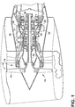
- FIG. 1 is a schematic cross-sectional diagram of a gas turbine engine 10 for an aircraft.
- the engine 10 includes, in downstream serial flow relationship, a fan section 12 including a fan 14, a booster or low pressure (LP) compressor 16, a high pressure (HP) compressor 18, a combustion section 20, a HP turbine 22, and a LP turbine 24.
- a HP shaft or spool 26 drivingly connects HP turbine 22 to HP compressor 18 and a LP shaft or spool 28 drivingly connects LP turbine 24 to LP compressor 16 and fan 14.
- HP turbine 22 includes an HP turbine rotor 30 having turbine blades 32 mounted at a periphery of rotor 30. Blades 32 extend radially outwardly from blade platforms 34 to radially outer blade tips 36.
- the gas turbine engine 10 can further include a temperature sensing probe assembly 38, illustrated in schematic outline, and positioned proximate to the aft of the engine 10, that is, downstream from the fan section 14.
- the temperature sensing probe assembly 38 can be positioned serially downstream from the combustion section 20 and upstream of at least one of the HP turbine 22 or LP turbine 24.
- the gas turbine engine 10 can include a set of temperature sensing probe assemblies 38 arranged about the engine 10, for instance, spaced about a circumference of the engine 10.
- the gas turbine engine 10 can operate such that the rotation of the fan 14 draws air into the HP compressor 18.
- the HP compressor 18 compresses the air and delivers the compressed air to the combustion section 20.
- the compressed air can be mixed with fuel, and the air/fuel mixture is ignited, expanding and generating high temperature exhaust gases.
- the engine exhaust gases traverse downstream, passing the set of temperature sensing probe assemblies 38, and through the HP and LP turbines 22, 24, generating the mechanical force for driving the respective HP and LP spools 26, 28. Finally, the exhaust gases, can be expelled from the rear of the engine 10.
- FIG 2 illustrates a non-limiting perspective view of the temperature sensing probe assembly 38 of FIG. 1 .
- the temperature sensing probe assembly 38 can include a first portion 40 and a second portion 42.
- Non-limiting aspects of the temperature sensing probe assembly 38 can be included wherein the first portion 40 is disposed outside of, or external to, an exhaust gas passage 44, while the second portion 42 is disposed within, or exposed to, the exhaust gas passage 44.
- the exhaust gas passage 44 can be at least partially defined by a gas turbine engine wall 46.
- Non-limiting configurations of the engine wall 46 can include an interior engine wall, an exterior engine wall, a low pressure turbine case, a turbine case wall, or the like.
- Non-limiting configurations of the temperature sensing assembly 38 can be included wherein at least one of the assembly 38, the first portion 40, or the second portion 42 can be supported by, coupled with, or fixed to the engine wall 46 by a mechanical fastener, such as a set of screws 48, or the like. While a single continuous engine wall 46 is illustrated, the wall 46 can include a set of independent walls, including but not limited to a low pressure turbine case or the like.
- Non-limiting aspects of the temperature sensing probe assembly 38 can be communicatively coupled with another temperature sensing probe assembly 38 or a controller module 50.
- the controller module 50 can be configured to receive a sensed or measured temperature, or a value representative or indicative thereof, from the temperature sensing probe assembly 38, and perform additional or separate functionality based upon the temperature.
- the controller module 50 can summate, average, or merge temperatures or values received from or provided by a set of temperature sensing probe assemblies 38.
- FIG. 3 illustrates a zoomed perspective view of the second portion 42 of the temperature sensing probe assembly 38 and is in the perspective of the substantial direction of movement of the exhaust gases during gas turbine engine operation.
- the temperature sensing probe assembly 38 can include a temperature sensing probe 54 and a housing 52 positioned around at least a portion of the temperature sensing probe 54.
- the temperature sensing probe assembly 38, the housing 52, and the temperature sensing probe 54 can define a common longitudinal axis 64.
- the housing 52 can include a first end 56 located proximate to the engine wall 46, and a spaced second end 58.
- the first end 56 can include an attachment point for positioning the temperature sensing probe assembly 38 relative to the engine wall 46.
- the attachment point can include a shoulder 59.
- the housing 52 can include an outer surface 60 having a generally conical construction wherein the first end 56 includes a first outer diameter and the second end 58 having a second outer diameter smaller than the first diameter.
- the generally conical construction of the outer surface 60 can linearly transition from the first outer diameter to the second outer diameter.
- non-limiting aspects of the housing 52 can include an interior sized to receive the temperature sensing probe 54, such as having a substantially cylindrical shape, for example.
- the housing 52 can include a metal-alloy material, or another material configured or selected for strength.
- the housing 52 material strength, the shape, the contours, the geometry, or the like can be selected or manufactured to counter vibrations or deformation, such as deformation over time in the high temperature environment of the exhaust gas passage 44.
- the housing 52 can be selected or manufactured to reduce stress due to induced cyclic loading, aerodynamic loading, or the like.
- the exhaust gas passage 44 can be exposed to temperatures greater than 1100 degrees Celsius.
- the housing 52 can also include at least one lengthened inlet opening 62 disposed to receive at least a portion of air or exhaust gases traversing the exhaust gas passage 44.
- the portion of the housing 52 having the inlet opening 62 will be referred to as the "fore" side of the housing 52, with the opposite side of the housing being the "aft" side of the housing 52.
- the inlet opening 62 can include a continuous opening extending along the longitudinal axis 64 of the housing 52 such that a lengthened portion of the underlying temperature sensing probe 54 corresponding to the inlet opening 62 is directly exposed to the exhaust gases traversing the exhaust gas passage 44.
- the inlet opening 62 can include a set of inlet openings 62 extending along respective portions of the longitudinal axis 64 of the housing 52 such that related portions of the underlying temperature sensing probe 54 corresponding to the set of inlet openings 62 are directly exposed to the exhaust gases traversing the exhaust gas passage 44.
- the inlet opening 62 can include a substantially ovate opening having a length of 0.003175 meters, a width of 0.0000762 meters, and a cross-sectional area of 0.0000761 square meters. Additional geometric configurations of the inlet opening 62 and area configurations can be included.
- the temperature sensing probe 54 can extend through the interior of the housing 52 and include a tip 66 located proximate to the second end 58.
- the temperature sensing probe 54 can be disposed or configured such that the tip 66 extends beyond the housing 52 opposite the engine wall 46.
- the tip 66 can extend beyond the housing 52 through an aperture 68 concentric to the longitudinal axis 64 of the housing 52.
- FIG. 4 illustrates another non-limiting perspective view of the temperature sensing probe assembly 38 from a perspective view taken along line IV-IV of FIG. 3 .
- the aft side of the housing 52 can further include a set of fluid passages or exhaust openings 70 spaced along the longitudinal axis 64.
- the set of exhaust openings 70 are spaced along a portion of the longitudinal axis 64 corresponding with, or related to, the lengthened inlet opening 62.
- the inlet opening 62 and the set of exhaust openings 70 define a housing flow path wherein a stream of air or exhaust gases (illustrated by arrows 72) received by the inlet opening 62 flows through the housing 52 to the set of exhaust opening 70.
- the at least a portion of the temperature sensor probe 54 can be exposed to the exhaust gas flow 72 via the inlet opening 62 and the set of exhaust openings 70.
- the number of the set of exhaust openings 70 can be larger than the number of the set of inlet openings 62.
- the set of exhaust openings 70 can be configured to reduce stress, vibration, deformation, induced cyclic loading, aerodynamic loading, or the like, on the housing 52.
- Non-limiting aspects of the disclosure can be included wherein the set of exhaust opening 70 are equally spaced along the longitudinal axis 64. Additionally, while the perspective view of FIG. 4 illustrates one set of exhaust openings 70 along the longitudinal axis 64, non-limiting aspects of the housing 52 can be included wherein a corresponding second set of exhaust openings 70 can be configured, disposed, mirrored or located on the opposing side of the housing 52, as well.
- the exhaust openings 70 can be substantially circular in shape, and can include a cross-sectional area of 0.00007935 square meters. Additional geometric configurations of the set of exhaust openings 70 and area configurations can be included. Additional non-limiting configurations can be included wherein the cross-sectional area of the inlet opening 62 can be approximately equal to, or substantially the same as the combined or summated cross-sectional areas of the set of exhaust openings 70.
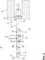
- FIG. 5 illustrates a cross-sectional view of the temperature sensing probe assembly 38 taken along line V-V of FIG. 3 .
- the temperature sensing probe 54 can include a first temperature sensor, such as a first thermocouple junction 74 located proximate to or nearer to the tip 66 or the second end 58 of the housing 52, and a second temperature sensor, such as a second thermocouple junction 76 located proximate to or nearer to the first end 56 or engine wall 46, relative to the first thermocouple junction 74.
- the first thermocouple junction 74 can be disposed or located such that it resides at approximately 35% of the low pressure turbine span radius, when included in the gas turbine engine.
- the "low pressure turbine span radius” can include the span measured from the low pressure turbine hub to the radially spaced case or wall (e.g. the low pressure turbine case wall). In another aspect of the disclosure, the "low pressure turbine span radius” can include the radial span of the exhaust gas flowpath. In another non-limiting aspect of the disclosure, the second thermocouple junction 76 can be disposed or located such that it resides at approximately 65% of the low-pressure turbine span radius, when included in the gas turbine engine. In yet another non-limiting aspect of the disclosure, the first thermocouple junction 74 can be disposed or located such that it resides at approximately 35% of the length of the temperature sensing probe assembly 38 inside the exhaust gas passage 44, measured from the tip 66. In another non-limiting aspect of the disclosure, the second thermocouple junction 76 can be disposed or located such that it resides at approximately 65% of the length of the temperature sensing probe assembly 38 inside the exhaust gas passage 44, measured from the tip 66.
- the first or second thermocouple junction 74, 76, or a combination thereof can be configured to operably sense the temperature of airflow communicating with the temperature sensor probe 54 proximate to the respective junction 74, 76.
- the first or second thermocouple junctions 74, 76 can be further communicatively coupled with, for example, a controller module, such as the controller module 50 of FIG. 2 , wherein the temperature sensed by at least one of the first or second thermocouple junctions 74, 76 can be reviewed, processed, analyzed, averaged, balanced, or otherwise determined.
- aspects of the disclosure can include configurations wherein the temperature sensing probe assembly 38 includes a controller module configured to perform at least a subset of processing, sensing, or determining operations, and further configured to provide the output of such operations to another controller module remote from the temperature sensing probe assembly 38.
- the inlet opening 62 of the housing 52 extends from at least a portion of the first thermocouple junction 74 to at least a portion of the second thermocouple junction 76. In another aspect of the disclosure, the inlet opening 62 of the housing 52 extends beyond the second thermocouple junction 76 towards the first end 56 or the shoulder 59 of the housing 52. In another non-limiting configuration, the inlet opening 62 of the housing 52 extends beyond the first thermocouple junction 74 toward the tip 66 or the second end 58 of the housing 52.
- the second thermocouple junction 76 can be spaced from the terminal end of the inlet opening 62, proximate to the first end 56, by a first distance 80.
- the first thermocouple junction 74 can be spaced from the terminal end of the inlet opening 62, proximate to the second end 58, by a second distance 86.
- the first distance 80 can be greater than a third distance 82 separating adjacent exhaust openings 70.
- the second distance 86 can be less than the third distance 82 separating adjacent exhaust openings 70.
- the set of exhaust openings 70 can be disposed, located, or configured to ensure or enable a predetermined or known amount of airflow through the temperature sensing probe assembly 38.
- the predetermined or known amount of airflow enabled can be selected to ensure or enable an accurate temperature sensing of the exhaust gases by at least one of the temperature sensing probe 54, the first thermocouple junction 74, the second thermocouple junction 76, or a combination thereof.
- a first exhaust opening 84 can be located, disposed, positioned, configured, or the like, between the second thermocouple junction 76 and the first end 56, the shoulder 59, or the terminal end of the inlet opening 62 proximate to the first end 56.
- At least a portion of the engine wall 46 can have a cooler temperature than the exhaust gases of the exhaust gas passage 44. This can be due to, for example, a thermally conductive path from the engine wall 46 to another, cooler portion of the engine, casing, pylon, aircraft, or environmental exposure outside of the engine. Regardless of the specific thermally conductive path of the engine wall 46, the removal of heat from the wall 46 can further remove heat from a portion of at least one of the housing 52 or temperature sensing probe 54 proximate to the engine wall 46.
- the removal of heat from the at least one of the housing 52 or temperature sensing probe 54, by the cooler engine wall 46, can operably skew, distort, or otherwise affect the accuracy of temperature-sensing capabilities of at least one of the first or second thermocouple junctions 74, 76. Stated another way, the removal of heat via the engine wall 46 can create a thermal gradient in the temperature sensing probe assembly 38 causing the sensed temperature or temperature reading to be lower than the "true" airflow or exhaust gas temperature.
- Non-limiting aspects of the disclosure can be included such that the configuration of the inlet opening(s) 62, the set of exhaust openings 70, or a combination thereof, are arranged to shift, adjust, or the like, a thermal gradient of the temperature sensing probe 54, the first thermocouple junction 74, the second thermocouple junction 76, the housing 52, or a combination thereof, away from the engine wall 46 or first end 56 of the housing 52.
- the configuration of the temperature sensing probe assembly 38 is arranged such that the cooler temperature of the engine wall 46 does not affect, or has less of an effect on the accuracy of the temperature-sensing capabilities of the temperature sensing probe 54 or probe assembly 38.
- the second thermocouple junction 76 can be surrounded by more housing 52 mass or volume, compared with the first thermocouple junction 74 (e.g. due to the conical shape of the housing 52). In this example, the second thermocouple junction 76 can take a longer period of time to respond to temperature changes, or can take a take a longer period of time to sense an a temperature change, when compared with the first thermocouple junction 74 (i.e. a "time lag").
- thermocouple junction 76 This phenomena can be countered or mitigated by arranging, disposing, or configuring the temperature sensing probe assembly 38 such that a greater or increased amount, a greater percentage, or a greater ratio of airflow received by the housing 52 is relatively directed to the second thermocouple junction 76, compared with the first thermocouple junction 74.
- approximately one third of total airflow received by the inlet opening 62 can be received by a lower portion 87 of the inlet opening 62, while the remaining two thirds of total airflow (e.g. twice the amount of airflow received by the lower portion 87) can be received by an upper portion 88 of the inlet opening 62.
- the lower portion 87 can be arranged or configured to at least partially deliver the airflow to the first thermocouple junction 74 while the upper portion 88 can be arranged or configured to at least partially deliver the airflow to the second thermocouple junction 76, such that the first and second thermocouple junctions 74, 76 have approximately or substantially the same or equal sensing or response time.
- the configuration can be arranged or selected, as stated, to reduce or decrease a time lag between the first and second thermocouple junctions 74, 76.
- thermocouple junction 76 The positioning of the second thermocouple junction 76 away from the portion of the inlet opening 62 closest to the first end 56 or shoulder 59 of the housing 52 by the first distance 80, and consequently further away from the thermal gradient of the temperature sensing probe assembly 38 or engine wall 46, enables the second thermocouple junction 76 to read, sense, or measure are more accurate temperature of the airflow or exhaust gas.
- thermocouple junction 76 This configuration is further enhanced by locating or disposing the first exhaust opening 84 between the second thermocouple junction 76 and the terminal end of the inlet opening 62 proximate to the first end 56 of housing 52, such that airflow received proximate to the terminal end of the inlet opening 62 will impinge on the temperature sensing probe 54 and will be exhausted out of the housing by the first exhaust opening 84 away from the second thermocouple junction 76.
- the thermal gradient due to the engine wall 46 is kept away, or is less effective at affecting the accuracy of the temperature measurements captured by the second thermocouple junction 76.
- FIG. 6 illustrates an axially-exploded cross-sectional view of the temperature sensing probe assembly 38, wherein the temperature sensing probe 54 is moved from the housing 52 along the longitudinal axis 64.
- the view of FIG. 6 illustrates the set of exhaust openings 70 on the aft of the housing 52, relative to the perspective view of FIGS. 4 and 5 .
- FIG. 7 illustrates a cross-sectional view of the temperature sensing probe assembly 38 taken along line VII-VII of FIG. 4 illustrating the matching sets of exhaust openings 70 on the sides of the housing 52.
- the sets of exhaust openings 70 can be radially offset from the axis 92 of the inlet opening 62, or radially offset from the longitudinal axis 64, compared with the inlet opening 62.
- the sets of exhaust openings 70 can be equally radially offset on both sides of the axis 92 of the inlet opening 62 or the longitudinal axis 64.
- the set of exhaust openings 70 can be radially offset from the inlet opening 62 by approximately 120 degrees. While only a single cross-sectional view of mirrored, matching, or paired exhaust openings 70 is illustrated, aspects of the disclosure can be included wherein additional exhaust openings 70 are mirrored, matched, or paired along the length of the longitudinal axis 64.
- an airflow such as a heated, a combusted, or an exhaust flow or stream
- the inlet opening 62 or the temperature sensing probe assembly 38 can be positioned, disposed, or the like, such that the inlet opening 62 is arranged essentially along a flow axis of the airflow 90 or stream of air to be sensed for temperature.
- the airflow 90 once received by the inlet opening 62, is directed toward the center of the temperature sensing assembly 38, such as toward the longitudinal axis 64, wherein it is in fluid communication with the temperature sensing probe 54.
- the airflow 90 is allow to impinge on the temperature sensor probe 54.
- the impingement on the temperature sensor probe 54 can be provided along the length of the inlet opening 62, proximate to the first thermocouple junction 74, proximate to the second thermocouple junction 76, or a combination or subset thereof.
- the airflow 90 is then directed about or around the temperature sensor probe 54, wherein it is vented or exhausted through at least one of the radially offset exhaust openings 70.
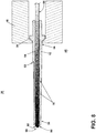
- FIG. 8 illustrates an example view of the temperature gradient of the temperature sensing probe 54 due to the removal of heat through or relative to the engine wall 46, previously discussed with regard to FIG. 5 .
- a first end 94 of the temperature sensing probe 54 is shaded lighter, representing a "cooler” temperature measurement, compared with a second end 96 of the temperature sensing probe 54, shaded darker to represent a "hotter” temperature measurement, relative to the first end 94.
- the example illustrated is merely one non-limited view demonstrating a representative temperature gradient due to heat loss through the cooler engine wall 46 for understanding, as explained herein. Additional gradients can be included.
- the aspects disclosed herein provide a temperature sensing probe assembly.
- One advantage that can be realized in the above aspects is that the above described aspects of the disclosure is that the temperature sensing probe assembly enables a higher airflow or a high rate of airflow through the housing to impinge the temperature sensing probe, resulting in a faster sensor response to changes in exhaust temperature.
- the configurations can include larger inlet openings and additional exhaust openings.
- the matching of cross-sectional areas between the inlet and exhaust openings can provide for a tailored or desired flowrate inside or through the probe assembly.
- a faster-responding temperature sensing probe assembly allows the engine control system to be more responsive to changes in engine operating conditions, and can increase the operating efficiency of the gas turbine engine by operating at a higher temperature or more combustion power while protecting the downstream components such as the turbine vanes and blades.
- a faster-responding temperature sensing probe assembly can thus operate the engine close to the thermal limits of the downstream components as the engine control system can detect and account for thermal spikes in the exhaust gas temperature more quickly, and adjust the engine operation to compensate accordingly.
- the difference in response time between the first and second thermocouple junctions is reduced.
- the reduction in difference of response time enables further confidence in faster reading of the temperature measurements.
- the variation of the first time constants of the first and second junctions to a step change in flow path temperature is reduced to approximately 0.5%, compared with a first time constraint approximately between 15 to 16% with conventional temperature sensing probe assemblies.
- Another advantage of the above-described aspects of the disclosure can include tailoring or optimizing the inlet and exhaust cross-sectional areas and locations to allow a larger mass flow of exhaust gas through the housing while maintain the structural strength required for the application, installation, or particular embodiment.
- thermocouple junction farther away from the thermal gradient produced by the engine wall, or another heat-removing component.
- the spacing of the thermocouple junction away from the thermal gradient enables a more accurate or "true” temperature sensing compared with conventional temperature sensing probe assemblies.
- the temperature error of the second thermocouple junction in a conventional probe assembly error of approximately 2-5 degree Fahrenheit
Description
- Turbine engines, and particularly gas turbine engines, also known as combustion turbine engines, are rotary engines that extract energy from a flow of combusted gases passing through the engine onto a multitude of turbine blades. Gas turbine engines have been used for land and nautical locomotion and power generation, but are most commonly used for aeronautical applications such as for airplanes, including helicopters. In airplanes, gas turbine engines are used for propulsion of the aircraft.
- During operation of the gas turbine engines, fuel is combusted to provide rotational energy and thrust through a set of turbines. In order to ensure or validate the gas turbine engine is operating as desired, a temperature sensor probe can be included in the engine wherein it is exposed to the exhaust gases. The temperature sensor can measure the temperature of the exhaust gas stream, and can provide a signal or measurement value to another system, such as an engine control system. The temperature sensor output can be used to, for example, protect the downstream engine components from temperatures that would exceed their design capabilities.
-
US 2,930,827 relates to a thermocouple and discloses features generally corresponding to the preamble ofclaim 1.US 2,496,806 relates to a gas temperature probe of a thermocouple type.US 3,451,268 relates to a cooled thermocouple.EP 2,607,871 A2 relates to a thermocouple. - A temperature sensing probe assembly is provided as defined in the appended claims. In one aspect, the present disclosure relates to a temperature sensing probe assembly including a temperature sensing probe having a tip and a first thermocouple junction located nearer the tip and a second thermocouple junction located nearer an attachment point for the temperature sensing probe assembly, and a housing positioned around at least a portion of the temperature sensing probe and having a set of inlet openings and having a set of exhaust openings. A stream of air flows through the housing from the inlet opening to the set of exhaust openings to establish a flow path through the housing and outputs of the first thermocouple junction and second thermocouple junction define an output for the temperature sensing probe and where the set of inlet openings and the set of exhaust openings are configured to increase the stream of air flowing around the second thermocouple junction as compared to an amount of the stream of air flowing around the first thermocouple junction.
- In another aspect, the present disclosure relates to an exhaust gas temperature sensing probe assembly for use in an aircraft engine, including a temperature sensing probe having a tip and a first thermocouple junction located nearer the tip and a second thermocouple junction located nearer an attachment point for the temperature sensing probe assembly, and a housing positioned around at least a portion of the temperature sensing probe and configured to operably couple to a turbine case within the engine and where the housing has a set of inlet openings that extend from at least a portion of the first thermocouple junction to at least a portion of the second thermocouple junction and having a set of exhaust openings. A stream of heated air flows through the housing from the set of inlet openings to the set of exhaust openings to establish a flow path through the housing, the case has a cooler temperature than the stream of heated air, and outputs of the first thermocouple junction and second thermocouple junction are averaged to define an output for the temperature sensing probe and wherein the configuration of the set of inlet openings and the set of exhaust openings is configured to provide a time response of the first thermocouple junction and the second thermocouple junction that are substantially the same.
- In yet another aspect, the present disclosure relates to a temperature sensing probe assembly including a temperature sensing probe having a length and a first thermocouple junction located at approximately 35% of the span of engine flow path and a second thermocouple junction located at approximately 65% of the span of engine flow path, and a housing positioned around at least a portion of the temperature sensing probe and having a set of inlet openings and a set of exhaust openings. A stream of air flows through the housing from the inlet opening to the set of exhaust openings to establish a flow path through the housing and outputs of the first thermocouple junction and second thermocouple junction are averaged to define an output for the temperature sensing probe and where the set of inlet openings and the set of exhaust openings is configured to increase the percentage of the stream of air flowing around the second thermocouple junction as compared to an amount of the stream of air flowing around the first thermocouple junction.
- In the drawings:
-
FIG. 1 illustrates a cross-sectional view of a gas turbine engine in accordance with various aspects described herein. -
FIG. 2 illustrates a perspective view of a temperature sensing probe assembly for the gas turbine engine ofFIG. 1 , in accordance with various aspects described herein. -
FIG. 3 illustrates another perspective view of the temperature sensing probe assembly ofFIG. 2 , in accordance with various aspects described herein. -
FIG. 4 illustrates another perspective view of the temperature sensing probe assembly ofFIG. 2 , normal to the view illustrated inFIG. 3 , in accordance with various aspects described herein. -
FIG. 5 illustrates a cross-sectional view of the temperature sensing probe assembly taken along line V-V ofFIG. 3 , in accordance with various aspects described herein. -
FIG. 6 illustrates an axially exploded cross-sectional view of the temperature sensing probe assembly ofFIG. 5 , in accordance with various aspects described herein. -
FIG. 7 illustrates a cross-sectional view of the temperature sensing probe assembly taken along line VII-VII ofFIG. 4 , in accordance with various aspects described herein. -
FIG. 8 illustrates an example temperature gradient of the temperature sensing probe assembly, in accordance with various aspects described herein. - Aspects of the disclosure can be implemented in any temperature sensing application, environment, apparatus, or method for sensing a temperature regardless of the function performed by the temperature sensing, or operable output, outcome, or function of the temperature sensing. While aspects of the disclosure are described with regard to a gas turbine engine for an aircraft, it will be understood that the aspects of the disclosure are not so limited and have general application in non-aircraft applications, such as other mobile applications and non-mobile industrial, commercial, and residential applications.
- While "a set of' various elements will be described, it will be understood that "a set" can include any number of the respective elements, including only one element. As used herein, the terms "axial" or "axially" refer to a dimension along a longitudinal axis of a described component. Also as used herein, the terms "radial" or "radially" refer to a dimension extending between a center longitudinal axis, an outer circumference, or a circular or annular component disposed relative to the axis. "Sensing" or "measuring" the temperature as described herein can include determining a value indicative of, or related to, the temperature, rather than directly sensing or measuring the temperature itself. The sensed or measured values can be provided to additional components. For instance, the value can be provided to a controller, and the controller can perform processing on the value to determine a temperature or an electrical characteristic representative of said temperature.
- Also used herein, a "thermocouple" or a "thermocouple junction" is a temperature sensing apparatus including one or more junctions of two dissimilar metals that produce an electrical potential representative of, or related to, a measure of the temperature or the medium to which the junctions are exposed. In one aspect of the disclosure, the junction or junctions can be mounted in a casing or housing, and can, in combination, form a "thermocouple probe." One non-limiting example of a thermocouple construction can be found in
US. Pat. No. 3,007,990 . - All directional references (e.g., radial, axial, upper, lower, upward, downward, left, right, lateral, front, back, top, bottom, above, below, vertical, horizontal, clockwise, counterclockwise, fore, aft) are only used for identification purposes to aid the reader's understanding of the disclosure, and do not create limitations, particularly as to the position, orientation, or use thereof. Connection references (e.g., attached, coupled, connected, and joined) are to be construed broadly and can include intermediate members between a collection of elements and relative movement between elements unless otherwise indicated. As such, connection references do not necessarily infer that two elements are directly connected and in fixed relation to each other. The exemplary drawings are for purposes of illustration only and the dimensions, positions, order and relative sizes reflected in the drawings attached hereto can vary.
-
FIG. 1 is a schematic cross-sectional diagram of agas turbine engine 10 for an aircraft. Theengine 10 includes, in downstream serial flow relationship, afan section 12 including afan 14, a booster or low pressure (LP)compressor 16, a high pressure (HP)compressor 18, acombustion section 20, a HPturbine 22, and aLP turbine 24. A HP shaft orspool 26 drivingly connects HPturbine 22 to HPcompressor 18 and a LP shaft orspool 28 drivingly connectsLP turbine 24 toLP compressor 16 andfan 14. HPturbine 22 includes an HPturbine rotor 30 havingturbine blades 32 mounted at a periphery ofrotor 30.Blades 32 extend radially outwardly from blade platforms 34 to radiallyouter blade tips 36. Thegas turbine engine 10 can further include a temperaturesensing probe assembly 38, illustrated in schematic outline, and positioned proximate to the aft of theengine 10, that is, downstream from thefan section 14. In one non-limiting example configuration, the temperaturesensing probe assembly 38 can be positioned serially downstream from thecombustion section 20 and upstream of at least one of the HPturbine 22 orLP turbine 24. In another non-limiting example configuration, thegas turbine engine 10 can include a set of temperaturesensing probe assemblies 38 arranged about theengine 10, for instance, spaced about a circumference of theengine 10. - The
gas turbine engine 10 can operate such that the rotation of thefan 14 draws air into the HPcompressor 18. The HPcompressor 18 compresses the air and delivers the compressed air to thecombustion section 20. In thecombustion section 20, the compressed air can be mixed with fuel, and the air/fuel mixture is ignited, expanding and generating high temperature exhaust gases. The engine exhaust gases, traverse downstream, passing the set of temperaturesensing probe assemblies 38, and through the HP andLP turbines LP spools engine 10. -
FIG 2 . illustrates a non-limiting perspective view of the temperaturesensing probe assembly 38 ofFIG. 1 . As shown, the temperaturesensing probe assembly 38 can include afirst portion 40 and asecond portion 42. Non-limiting aspects of the temperaturesensing probe assembly 38 can be included wherein thefirst portion 40 is disposed outside of, or external to, anexhaust gas passage 44, while thesecond portion 42 is disposed within, or exposed to, theexhaust gas passage 44. In the illustrated example, theexhaust gas passage 44 can be at least partially defined by a gasturbine engine wall 46. Non-limiting configurations of theengine wall 46 can include an interior engine wall, an exterior engine wall, a low pressure turbine case, a turbine case wall, or the like. Non-limiting configurations of thetemperature sensing assembly 38 can be included wherein at least one of theassembly 38, thefirst portion 40, or thesecond portion 42 can be supported by, coupled with, or fixed to theengine wall 46 by a mechanical fastener, such as a set ofscrews 48, or the like. While a singlecontinuous engine wall 46 is illustrated, thewall 46 can include a set of independent walls, including but not limited to a low pressure turbine case or the like. - Non-limiting aspects of the temperature
sensing probe assembly 38 can be communicatively coupled with another temperaturesensing probe assembly 38 or acontroller module 50. Thecontroller module 50 can be configured to receive a sensed or measured temperature, or a value representative or indicative thereof, from the temperaturesensing probe assembly 38, and perform additional or separate functionality based upon the temperature. In a non-limiting configuration of the disclosure, thecontroller module 50 can summate, average, or merge temperatures or values received from or provided by a set of temperaturesensing probe assemblies 38. -
FIG. 3 illustrates a zoomed perspective view of thesecond portion 42 of the temperaturesensing probe assembly 38 and is in the perspective of the substantial direction of movement of the exhaust gases during gas turbine engine operation. The temperaturesensing probe assembly 38 can include atemperature sensing probe 54 and ahousing 52 positioned around at least a portion of thetemperature sensing probe 54. In one non-limiting aspect of the disclosure, the temperaturesensing probe assembly 38, thehousing 52, and thetemperature sensing probe 54 can define a commonlongitudinal axis 64. - The
housing 52 can include afirst end 56 located proximate to theengine wall 46, and a spacedsecond end 58. Thefirst end 56 can include an attachment point for positioning the temperaturesensing probe assembly 38 relative to theengine wall 46. In one non-limiting configuration, the attachment point can include ashoulder 59. In a non-limiting configuration, thehousing 52 can include anouter surface 60 having a generally conical construction wherein thefirst end 56 includes a first outer diameter and thesecond end 58 having a second outer diameter smaller than the first diameter. In this non-limiting configuration, the generally conical construction of theouter surface 60 can linearly transition from the first outer diameter to the second outer diameter. Regardless of the configuration of thehousing 52 orouter surface 60, non-limiting aspects of thehousing 52 can include an interior sized to receive thetemperature sensing probe 54, such as having a substantially cylindrical shape, for example. In one non-limiting configuration, thehousing 52 can include a metal-alloy material, or another material configured or selected for strength. Thehousing 52 material strength, the shape, the contours, the geometry, or the like can be selected or manufactured to counter vibrations or deformation, such as deformation over time in the high temperature environment of theexhaust gas passage 44. In another non-limiting example, thehousing 52 can be selected or manufactured to reduce stress due to induced cyclic loading, aerodynamic loading, or the like. In one example, theexhaust gas passage 44 can be exposed to temperatures greater than 1100 degrees Celsius. - The
housing 52 can also include at least one lengthened inlet opening 62 disposed to receive at least a portion of air or exhaust gases traversing theexhaust gas passage 44. As used herein, the portion of thehousing 52 having theinlet opening 62 will be referred to as the "fore" side of thehousing 52, with the opposite side of the housing being the "aft" side of thehousing 52. In one non-limiting example, the inlet opening 62 can include a continuous opening extending along thelongitudinal axis 64 of thehousing 52 such that a lengthened portion of the underlyingtemperature sensing probe 54 corresponding to theinlet opening 62 is directly exposed to the exhaust gases traversing theexhaust gas passage 44. In another non-limiting example, the inlet opening 62 can include a set ofinlet openings 62 extending along respective portions of thelongitudinal axis 64 of thehousing 52 such that related portions of the underlyingtemperature sensing probe 54 corresponding to the set ofinlet openings 62 are directly exposed to the exhaust gases traversing theexhaust gas passage 44. In one non-limiting configuration, the inlet opening 62 can include a substantially ovate opening having a length of 0.003175 meters, a width of 0.0000762 meters, and a cross-sectional area of 0.0000761 square meters. Additional geometric configurations of theinlet opening 62 and area configurations can be included. - The
temperature sensing probe 54 can extend through the interior of thehousing 52 and include atip 66 located proximate to thesecond end 58. In one non-limiting configuration of the temperaturesensing probe assembly 38,temperature sensing probe 54, orhousing 52, thetemperature sensing probe 54 can be disposed or configured such that thetip 66 extends beyond thehousing 52 opposite theengine wall 46. In one example configuration, thetip 66 can extend beyond thehousing 52 through anaperture 68 concentric to thelongitudinal axis 64 of thehousing 52. -
FIG. 4 illustrates another non-limiting perspective view of the temperaturesensing probe assembly 38 from a perspective view taken along line IV-IV ofFIG. 3 . As shown, the aft side of thehousing 52 can further include a set of fluid passages orexhaust openings 70 spaced along thelongitudinal axis 64. In one non-limiting aspect of the disclosure, the set ofexhaust openings 70 are spaced along a portion of thelongitudinal axis 64 corresponding with, or related to, the lengthenedinlet opening 62. Taken together, theinlet opening 62 and the set ofexhaust openings 70 define a housing flow path wherein a stream of air or exhaust gases (illustrated by arrows 72) received by the inlet opening 62 flows through thehousing 52 to the set ofexhaust opening 70. In this sense, the at least a portion of thetemperature sensor probe 54 can be exposed to theexhaust gas flow 72 via theinlet opening 62 and the set ofexhaust openings 70. In one non-limiting configuration of thehousing 52, the number of the set ofexhaust openings 70 can be larger than the number of the set ofinlet openings 62. In another non-limiting configuration, the set ofexhaust openings 70 can be configured to reduce stress, vibration, deformation, induced cyclic loading, aerodynamic loading, or the like, on thehousing 52. - Non-limiting aspects of the disclosure can be included wherein the set of
exhaust opening 70 are equally spaced along thelongitudinal axis 64. Additionally, while the perspective view ofFIG. 4 illustrates one set ofexhaust openings 70 along thelongitudinal axis 64, non-limiting aspects of thehousing 52 can be included wherein a corresponding second set ofexhaust openings 70 can be configured, disposed, mirrored or located on the opposing side of thehousing 52, as well. In one non-limiting configuration, theexhaust openings 70 can be substantially circular in shape, and can include a cross-sectional area of 0.00007935 square meters. Additional geometric configurations of the set ofexhaust openings 70 and area configurations can be included. Additional non-limiting configurations can be included wherein the cross-sectional area of the inlet opening 62 can be approximately equal to, or substantially the same as the combined or summated cross-sectional areas of the set ofexhaust openings 70. -
FIG. 5 illustrates a cross-sectional view of the temperaturesensing probe assembly 38 taken along line V-V ofFIG. 3 . As shown, thetemperature sensing probe 54 can include a first temperature sensor, such as afirst thermocouple junction 74 located proximate to or nearer to thetip 66 or thesecond end 58 of thehousing 52, and a second temperature sensor, such as asecond thermocouple junction 76 located proximate to or nearer to thefirst end 56 orengine wall 46, relative to thefirst thermocouple junction 74. In one non-limiting aspect of the disclosure, thefirst thermocouple junction 74 can be disposed or located such that it resides at approximately 35% of the low pressure turbine span radius, when included in the gas turbine engine. As used herein, the "low pressure turbine span radius" can include the span measured from the low pressure turbine hub to the radially spaced case or wall (e.g. the low pressure turbine case wall). In another aspect of the disclosure, the "low pressure turbine span radius" can include the radial span of the exhaust gas flowpath. In another non-limiting aspect of the disclosure, thesecond thermocouple junction 76 can be disposed or located such that it resides at approximately 65% of the low-pressure turbine span radius, when included in the gas turbine engine. In yet another non-limiting aspect of the disclosure, thefirst thermocouple junction 74 can be disposed or located such that it resides at approximately 35% of the length of the temperaturesensing probe assembly 38 inside theexhaust gas passage 44, measured from thetip 66. In another non-limiting aspect of the disclosure, thesecond thermocouple junction 76 can be disposed or located such that it resides at approximately 65% of the length of the temperaturesensing probe assembly 38 inside theexhaust gas passage 44, measured from thetip 66. - The first or
second thermocouple junction temperature sensor probe 54 proximate to therespective junction second thermocouple junctions controller module 50 ofFIG. 2 , wherein the temperature sensed by at least one of the first orsecond thermocouple junctions sensing probe assembly 38 includes a controller module configured to perform at least a subset of processing, sensing, or determining operations, and further configured to provide the output of such operations to another controller module remote from the temperaturesensing probe assembly 38. - In one aspect of the disclosure, the inlet opening 62 of the
housing 52 extends from at least a portion of thefirst thermocouple junction 74 to at least a portion of thesecond thermocouple junction 76. In another aspect of the disclosure, the inlet opening 62 of thehousing 52 extends beyond thesecond thermocouple junction 76 towards thefirst end 56 or theshoulder 59 of thehousing 52. In another non-limiting configuration, the inlet opening 62 of thehousing 52 extends beyond thefirst thermocouple junction 74 toward thetip 66 or thesecond end 58 of thehousing 52. - In one non-limiting configuration, the
second thermocouple junction 76 can be spaced from the terminal end of theinlet opening 62, proximate to thefirst end 56, by afirst distance 80. In another non-limiting configuration, thefirst thermocouple junction 74 can be spaced from the terminal end of theinlet opening 62, proximate to thesecond end 58, by asecond distance 86. As shown, thefirst distance 80 can be greater than athird distance 82 separatingadjacent exhaust openings 70. Similarly, thesecond distance 86 can be less than thethird distance 82 separatingadjacent exhaust openings 70. - The set of
exhaust openings 70 can be disposed, located, or configured to ensure or enable a predetermined or known amount of airflow through the temperaturesensing probe assembly 38. The predetermined or known amount of airflow enabled can be selected to ensure or enable an accurate temperature sensing of the exhaust gases by at least one of thetemperature sensing probe 54, thefirst thermocouple junction 74, thesecond thermocouple junction 76, or a combination thereof. For example, in one non-limiting aspect of the disclosure, afirst exhaust opening 84 can be located, disposed, positioned, configured, or the like, between thesecond thermocouple junction 76 and thefirst end 56, theshoulder 59, or the terminal end of the inlet opening 62 proximate to thefirst end 56. - Aspects of the disclosure can be included wherein at least a portion of the
engine wall 46 can have a cooler temperature than the exhaust gases of theexhaust gas passage 44. This can be due to, for example, a thermally conductive path from theengine wall 46 to another, cooler portion of the engine, casing, pylon, aircraft, or environmental exposure outside of the engine. Regardless of the specific thermally conductive path of theengine wall 46, the removal of heat from thewall 46 can further remove heat from a portion of at least one of thehousing 52 ortemperature sensing probe 54 proximate to theengine wall 46. The removal of heat from the at least one of thehousing 52 ortemperature sensing probe 54, by thecooler engine wall 46, can operably skew, distort, or otherwise affect the accuracy of temperature-sensing capabilities of at least one of the first orsecond thermocouple junctions engine wall 46 can create a thermal gradient in the temperaturesensing probe assembly 38 causing the sensed temperature or temperature reading to be lower than the "true" airflow or exhaust gas temperature. - Non-limiting aspects of the disclosure can be included such that the configuration of the inlet opening(s) 62, the set of
exhaust openings 70, or a combination thereof, are arranged to shift, adjust, or the like, a thermal gradient of thetemperature sensing probe 54, thefirst thermocouple junction 74, thesecond thermocouple junction 76, thehousing 52, or a combination thereof, away from theengine wall 46 orfirst end 56 of thehousing 52. Stated another way, the configuration of the temperaturesensing probe assembly 38 is arranged such that the cooler temperature of theengine wall 46 does not affect, or has less of an effect on the accuracy of the temperature-sensing capabilities of thetemperature sensing probe 54 orprobe assembly 38. - In one non-limiting example configuration, the
second thermocouple junction 76 can be surrounded bymore housing 52 mass or volume, compared with the first thermocouple junction 74 (e.g. due to the conical shape of the housing 52). In this example, thesecond thermocouple junction 76 can take a longer period of time to respond to temperature changes, or can take a take a longer period of time to sense an a temperature change, when compared with the first thermocouple junction 74 (i.e. a "time lag"). This phenomena can be countered or mitigated by arranging, disposing, or configuring the temperaturesensing probe assembly 38 such that a greater or increased amount, a greater percentage, or a greater ratio of airflow received by thehousing 52 is relatively directed to thesecond thermocouple junction 76, compared with thefirst thermocouple junction 74. - For instance, in one non-limiting configuration, approximately one third of total airflow received by the inlet opening 62 can be received by a
lower portion 87 of theinlet opening 62, while the remaining two thirds of total airflow (e.g. twice the amount of airflow received by the lower portion 87) can be received by an upper portion 88 of theinlet opening 62. In this sense, thelower portion 87 can be arranged or configured to at least partially deliver the airflow to thefirst thermocouple junction 74 while the upper portion 88 can be arranged or configured to at least partially deliver the airflow to thesecond thermocouple junction 76, such that the first andsecond thermocouple junctions second thermocouple junctions - The positioning of the
second thermocouple junction 76 away from the portion of the inlet opening 62 closest to thefirst end 56 orshoulder 59 of thehousing 52 by thefirst distance 80, and consequently further away from the thermal gradient of the temperaturesensing probe assembly 38 orengine wall 46, enables thesecond thermocouple junction 76 to read, sense, or measure are more accurate temperature of the airflow or exhaust gas. This configuration is further enhanced by locating or disposing thefirst exhaust opening 84 between thesecond thermocouple junction 76 and the terminal end of the inlet opening 62 proximate to thefirst end 56 ofhousing 52, such that airflow received proximate to the terminal end of theinlet opening 62 will impinge on thetemperature sensing probe 54 and will be exhausted out of the housing by thefirst exhaust opening 84 away from thesecond thermocouple junction 76. By directing the received airflow proximate to theengine wall 46 away from thesecond thermocouple junction 76, the thermal gradient due to theengine wall 46 is kept away, or is less effective at affecting the accuracy of the temperature measurements captured by thesecond thermocouple junction 76. -
FIG. 6 illustrates an axially-exploded cross-sectional view of the temperaturesensing probe assembly 38, wherein thetemperature sensing probe 54 is moved from thehousing 52 along thelongitudinal axis 64. The view ofFIG. 6 illustrates the set ofexhaust openings 70 on the aft of thehousing 52, relative to the perspective view ofFIGS. 4 and5 . -
FIG. 7 illustrates a cross-sectional view of the temperaturesensing probe assembly 38 taken along line VII-VII ofFIG. 4 illustrating the matching sets ofexhaust openings 70 on the sides of thehousing 52. As shown, the sets ofexhaust openings 70 can be radially offset from theaxis 92 of theinlet opening 62, or radially offset from thelongitudinal axis 64, compared with theinlet opening 62. In one non-limiting configuration, the sets ofexhaust openings 70 can be equally radially offset on both sides of theaxis 92 of the inlet opening 62 or thelongitudinal axis 64. In one non-limiting configuration, the set ofexhaust openings 70 can be radially offset from the inlet opening 62 by approximately 120 degrees. While only a single cross-sectional view of mirrored, matching, or pairedexhaust openings 70 is illustrated, aspects of the disclosure can be included whereinadditional exhaust openings 70 are mirrored, matched, or paired along the length of thelongitudinal axis 64. - As shown, a portion of an airflow (illustrated as arrows 90), such as a heated, a combusted, or an exhaust flow or stream can be received by the inlet opening 62 of the
housing 52. Theinlet opening 62 or the temperaturesensing probe assembly 38 can be positioned, disposed, or the like, such that theinlet opening 62 is arranged essentially along a flow axis of theairflow 90 or stream of air to be sensed for temperature. Theairflow 90, once received by theinlet opening 62, is directed toward the center of thetemperature sensing assembly 38, such as toward thelongitudinal axis 64, wherein it is in fluid communication with thetemperature sensing probe 54. In one non-limiting aspect of the disclosure, theairflow 90 is allow to impinge on thetemperature sensor probe 54. The impingement on thetemperature sensor probe 54 can be provided along the length of theinlet opening 62, proximate to thefirst thermocouple junction 74, proximate to thesecond thermocouple junction 76, or a combination or subset thereof. Theairflow 90 is then directed about or around thetemperature sensor probe 54, wherein it is vented or exhausted through at least one of the radially offsetexhaust openings 70. -
FIG. 8 illustrates an example view of the temperature gradient of thetemperature sensing probe 54 due to the removal of heat through or relative to theengine wall 46, previously discussed with regard toFIG. 5 . As shown, afirst end 94 of thetemperature sensing probe 54 is shaded lighter, representing a "cooler" temperature measurement, compared with asecond end 96 of thetemperature sensing probe 54, shaded darker to represent a "hotter" temperature measurement, relative to thefirst end 94. The example illustrated is merely one non-limited view demonstrating a representative temperature gradient due to heat loss through thecooler engine wall 46 for understanding, as explained herein. Additional gradients can be included. - Many other possible aspects and configurations in addition to that shown in the above figures are contemplated by the present disclosure. Additionally, the design and placement of the various components can be rearranged such that a number of different configurations could be realized.
- The aspects disclosed herein provide a temperature sensing probe assembly. One advantage that can be realized in the above aspects is that the above described aspects of the disclosure is that the temperature sensing probe assembly enables a higher airflow or a high rate of airflow through the housing to impinge the temperature sensing probe, resulting in a faster sensor response to changes in exhaust temperature. The configurations can include larger inlet openings and additional exhaust openings. Furthermore, the matching of cross-sectional areas between the inlet and exhaust openings can provide for a tailored or desired flowrate inside or through the probe assembly. A faster-responding temperature sensing probe assembly allows the engine control system to be more responsive to changes in engine operating conditions, and can increase the operating efficiency of the gas turbine engine by operating at a higher temperature or more combustion power while protecting the downstream components such as the turbine vanes and blades. A faster-responding temperature sensing probe assembly can thus operate the engine close to the thermal limits of the downstream components as the engine control system can detect and account for thermal spikes in the exhaust gas temperature more quickly, and adjust the engine operation to compensate accordingly.
- Additionally, by arranging the configuration of the airflow received by or proximate to the second thermocouple junction relative to the first thermocouple junction, the difference in response time between the first and second thermocouple junctions is reduced. The reduction in difference of response time enables further confidence in faster reading of the temperature measurements. In one example configuration, the variation of the first time constants of the first and second junctions to a step change in flow path temperature is reduced to approximately 0.5%, compared with a first time constraint approximately between 15 to 16% with conventional temperature sensing probe assemblies.
- Another advantage of the above-described aspects of the disclosure can include tailoring or optimizing the inlet and exhaust cross-sectional areas and locations to allow a larger mass flow of exhaust gas through the housing while maintain the structural strength required for the application, installation, or particular embodiment.
- Yet another advantage of the above-described aspects of the disclosure includes spacing the second thermocouple junction farther away from the thermal gradient produced by the engine wall, or another heat-removing component. The spacing of the thermocouple junction away from the thermal gradient enables a more accurate or "true" temperature sensing compared with conventional temperature sensing probe assemblies. In one example configuration, the temperature error of the second thermocouple junction in a conventional probe assembly (error of approximately 2-5 degree Fahrenheit) can be reduced to less than 1 degree Fahrenheit using the above-described aspects, between a 55 to 82% improvement.
- This written description uses examples to disclose aspects of the disclosure, including the best mode, and also to enable any person skilled in the art to practice aspects of the disclosure, including making and using any devices or systems and performing any incorporated methods. The patentable scope of the disclosure is defined by the claims, and can include other examples that occur to those skilled in the art. Such other examples are intended to be within the scope of the claims if they have structural elements that do not differ from the literal language of the claims, or if they include equivalent structural elements with insubstantial differences from the literal languages of the claims.
Claims (10)
- A temperature sensing probe assembly (38), comprising:a temperature sensing probe (54) having a tip (66) and a first thermocouple junction (74) located nearer the tip (66) and a second thermocouple junction (76) located nearer an attachment point for the temperature sensing probe assembly (38); anda housing (52) positioned around at least a portion of the temperature sensing probe (54);characterized in:the housing (52) having a set of inlet openings (62) and having a set of exhaust openings (70);wherein a stream of air flows through the housing (52) from the inlet opening (62) to the set of exhaust openings (70) to establish a flow path through the housing (52) and outputs of the first thermocouple junction (74) and second thermocouple junction (76) define an output for the temperature sensing probe (54) and where the set of inlet openings (62) and the set of exhaust openings (70) are configured to increase the stream of air flowing around the second thermocouple junction (76) as compared to an amount of the stream of air flowing around the first thermocouple junction (74).
- The temperature sensing probe assembly (38) of claim 1, wherein the set of inlet openings (62) and the set of exhaust openings (70) are configured to increase a percentage of the stream of air flowing around the second thermocouple junction (76) such that a time lag of the second thermocouple junction (76) is decreased compared to the first thermocouple junction (74).
- The temperature sensing probe assembly (38) of either of claim 1 or 2, wherein the set of inlet openings (62) is a lengthened inlet opening (62) that extends from at least a portion of the first thermocouple junction (74) to at least a portion of the second thermocouple junction (76).
- The temperature sensing probe assembly (38) of any preceding claim, wherein at least one of the set of exhaust openings (70) is located between the second thermocouple junction (76) and the attachment point for the temperature sensing probe assembly (38).
- The temperature sensing probe assembly (38) of claim 3 or any claim dependent thereon, wherein the lengthened inlet opening (62) extends beyond the first thermocouple junction (74) and the second thermocouple junction (76).
- The temperature sensing probe assembly (38) of any preceding claim, wherein the set of inlet openings (62) are positioned essentially along a flow axis (90) of the stream of air.
- The temperature sensing probe assembly (38) of any preceding claim, wherein the set of exhaust openings are radially offset from the axis (92) of the set of inlet openings.
- The temperature sensing probe assembly (38) of any preceding claim, wherein the set of exhaust openings are radially offset on both sides of the axis (92) of the set of inlet openings.
- The temperature sensing probe assembly (38) of claim 8, wherein the exhaust openings offset on both sides are paired along a length of the housing.
- The temperature sensing probe assembly (38) of any preceding claim, wherein the percentage of the stream of air flowing around the second thermocouple junction (76) is at least twice as much as the percentage of air flowing around the first thermocouple junction (74).
Applications Claiming Priority (1)
| Application Number | Priority Date | Filing Date | Title |
|---|---|---|---|
| US15/281,612 US10174631B2 (en) | 2016-09-30 | 2016-09-30 | Exhaust gas temperature sensing probe assembly |
Publications (2)
| Publication Number | Publication Date |
|---|---|
| EP3301419A1 EP3301419A1 (en) | 2018-04-04 |
| EP3301419B1 true EP3301419B1 (en) | 2019-06-12 |
Family
ID=59969067
Family Applications (1)
| Application Number | Title | Priority Date | Filing Date |
|---|---|---|---|
| EP17193187.6A Active EP3301419B1 (en) | 2016-09-30 | 2017-09-26 | Exhaust gas temperature sensing probe assembly |
Country Status (4)
| Country | Link |
|---|---|
| US (1) | US10174631B2 (en) |
| EP (1) | EP3301419B1 (en) |
| JP (1) | JP2018072328A (en) |
| CA (1) | CA2979776A1 (en) |
Families Citing this family (2)
| Publication number | Priority date | Publication date | Assignee | Title |
|---|---|---|---|---|
| US10254180B2 (en) | 2016-09-30 | 2019-04-09 | Unison Industries, Llc | Exhaust gas temperature sensing probe assembly |
| US10197454B2 (en) | 2016-09-30 | 2019-02-05 | General Electric Company | Exhaust gas temperature sensing probe assembly |
Family Cites Families (17)
| Publication number | Priority date | Publication date | Assignee | Title |
|---|---|---|---|---|
| US2496806A (en) | 1946-11-27 | 1950-02-07 | United Aircraft Corp | Gas temperature probe of the thermocouple type |
| US2930827A (en) * | 1953-07-23 | 1960-03-29 | Gen Motors Corp | Thermocouple |
| US3007990A (en) | 1960-03-29 | 1961-11-07 | Gen Electric | Thermocouple |
| US3451268A (en) | 1967-05-18 | 1969-06-24 | Gen Motors Corp | Cooled thermocouple |
| US4467134A (en) | 1983-06-30 | 1984-08-21 | General Electric Company | Thermocouple with out-of-line aspiration holes |
| US4499330A (en) | 1983-12-23 | 1985-02-12 | General Electric Company | Anti-vibration support for thermocouple tip |
| US5427452A (en) * | 1994-01-10 | 1995-06-27 | Thiokol Corporation | Rugged quick-response thermocouple for use in evaluating gas generants and gas generators |
| DE19544880B4 (en) * | 1995-12-01 | 2005-01-05 | Alstom | temperature probe |
| DE19600822A1 (en) * | 1996-01-11 | 1997-07-17 | Basf Ag | Temperature measurement probe |
| US6076963A (en) * | 1998-10-20 | 2000-06-20 | Avionics Specialties, Inc. | Aircraft probe with integral air temperature sensor |
| US7467891B2 (en) * | 2005-11-29 | 2008-12-23 | Sensata Technologies, Inc. | Sensor arrangement for measuring a pressure and a temperature in a fluid |
| DE102006007221B3 (en) * | 2006-02-15 | 2007-09-06 | Epcos Ag | Sensor and temperature measuring device |
| US8764289B2 (en) | 2011-12-21 | 2014-07-01 | Unison Industries, Llc | Expandable/retractable thermocouple |
| KR101277773B1 (en) | 2012-12-28 | 2013-06-24 | 우진 일렉트로나이트(주) | Replacement device for holder and holder assembly |
| US10197454B2 (en) | 2016-09-30 | 2019-02-05 | General Electric Company | Exhaust gas temperature sensing probe assembly |
| USD803706S1 (en) | 2016-09-30 | 2017-11-28 | Unison Industries, Llc | Sensor probe housing |
| US10254180B2 (en) | 2016-09-30 | 2019-04-09 | Unison Industries, Llc | Exhaust gas temperature sensing probe assembly |
-
2016
- 2016-09-30 US US15/281,612 patent/US10174631B2/en active Active
-
2017
- 2017-09-19 JP JP2017178476A patent/JP2018072328A/en active Pending
- 2017-09-21 CA CA2979776A patent/CA2979776A1/en not_active Abandoned
- 2017-09-26 EP EP17193187.6A patent/EP3301419B1/en active Active
Non-Patent Citations (1)
| Title |
|---|
| None * |
Also Published As
| Publication number | Publication date |
|---|---|
| US10174631B2 (en) | 2019-01-08 |
| EP3301419A1 (en) | 2018-04-04 |
| US20180094534A1 (en) | 2018-04-05 |
| CA2979776A1 (en) | 2018-03-30 |
| JP2018072328A (en) | 2018-05-10 |
Similar Documents
| Publication | Publication Date | Title |
|---|---|---|
| EP3301417B1 (en) | Exhaust gas temperature sensing probe assembly | |
| EP3543473B1 (en) | Gas turbine engine having a splitter with a flush-mounted combined static pressure and temperature probe | |
| EP3301418B1 (en) | Exhaust gas temperature sensing probe assembly | |
| CN110615091A (en) | Control system | |
| EP3301419B1 (en) | Exhaust gas temperature sensing probe assembly | |
| EP3034994B1 (en) | System and method for measuring over tip leakage | |
| EP3418703B1 (en) | Air temperature sensor | |
| EP3875744B1 (en) | Method for fuel delivery | |
| US20230193821A1 (en) | Turbine engine exhaust gas temperature sensor | |
| CN109115370B (en) | Air temperature sensor and method for reducing error | |
| US11175187B2 (en) | Air temperature sensor having a bushing | |
| GB2577592A (en) | Exhaust gas temperature sensor | |
| EP2672063A2 (en) | Turbomachine bucket assembly, corresponding turbomachine and method of cooling a turbomachine bucket assembly |
Legal Events
| Date | Code | Title | Description |
|---|---|---|---|
| PUAI | Public reference made under article 153(3) epc to a published international application that has entered the european phase |
Free format text: ORIGINAL CODE: 0009012 |
|
| STAA | Information on the status of an ep patent application or granted ep patent |
Free format text: STATUS: THE APPLICATION HAS BEEN PUBLISHED |
|
| AK | Designated contracting states |
Kind code of ref document: A1 Designated state(s): AL AT BE BG CH CY CZ DE DK EE ES FI FR GB GR HR HU IE IS IT LI LT LU LV MC MK MT NL NO PL PT RO RS SE SI SK SM TR |
|
| AX | Request for extension of the european patent |
Extension state: BA ME |
|
| STAA | Information on the status of an ep patent application or granted ep patent |
Free format text: STATUS: REQUEST FOR EXAMINATION WAS MADE |
|
| 17P | Request for examination filed |
Effective date: 20181004 |
|
| RBV | Designated contracting states (corrected) |
Designated state(s): AL AT BE BG CH CY CZ DE DK EE ES FI FR GB GR HR HU IE IS IT LI LT LU LV MC MK MT NL NO PL PT RO RS SE SI SK SM TR |
|
| GRAP | Despatch of communication of intention to grant a patent |
Free format text: ORIGINAL CODE: EPIDOSNIGR1 |
|
| STAA | Information on the status of an ep patent application or granted ep patent |
Free format text: STATUS: GRANT OF PATENT IS INTENDED |
|
| INTG | Intention to grant announced |
Effective date: 20190110 |
|
| GRAS | Grant fee paid |
Free format text: ORIGINAL CODE: EPIDOSNIGR3 |
|
| GRAA | (expected) grant |
Free format text: ORIGINAL CODE: 0009210 |
|
| STAA | Information on the status of an ep patent application or granted ep patent |
Free format text: STATUS: THE PATENT HAS BEEN GRANTED |
|
| AK | Designated contracting states |
Kind code of ref document: B1 Designated state(s): AL AT BE BG CH CY CZ DE DK EE ES FI FR GB GR HR HU IE IS IT LI LT LU LV MC MK MT NL NO PL PT RO RS SE SI SK SM TR |
|
| REG | Reference to a national code |
Ref country code: GB Ref legal event code: FG4D |
|
| REG | Reference to a national code |
Ref country code: CH Ref legal event code: EP |
|
| REG | Reference to a national code |
Ref country code: AT Ref legal event code: REF Ref document number: 1143176 Country of ref document: AT Kind code of ref document: T Effective date: 20190615 |
|
| REG | Reference to a national code |
Ref country code: DE Ref legal event code: R096 Ref document number: 602017004457 Country of ref document: DE |
|
| REG | Reference to a national code |
Ref country code: IE Ref legal event code: FG4D |
|
| REG | Reference to a national code |
Ref country code: NL Ref legal event code: MP Effective date: 20190612 |
|
| REG | Reference to a national code |
Ref country code: LT Ref legal event code: MG4D |
|
| PG25 | Lapsed in a contracting state [announced via postgrant information from national office to epo] |
Ref country code: FI Free format text: LAPSE BECAUSE OF FAILURE TO SUBMIT A TRANSLATION OF THE DESCRIPTION OR TO PAY THE FEE WITHIN THE PRESCRIBED TIME-LIMIT Effective date: 20190612 Ref country code: SE Free format text: LAPSE BECAUSE OF FAILURE TO SUBMIT A TRANSLATION OF THE DESCRIPTION OR TO PAY THE FEE WITHIN THE PRESCRIBED TIME-LIMIT Effective date: 20190612 Ref country code: LT Free format text: LAPSE BECAUSE OF FAILURE TO SUBMIT A TRANSLATION OF THE DESCRIPTION OR TO PAY THE FEE WITHIN THE PRESCRIBED TIME-LIMIT Effective date: 20190612 Ref country code: AL Free format text: LAPSE BECAUSE OF FAILURE TO SUBMIT A TRANSLATION OF THE DESCRIPTION OR TO PAY THE FEE WITHIN THE PRESCRIBED TIME-LIMIT Effective date: 20190612 Ref country code: NO Free format text: LAPSE BECAUSE OF FAILURE TO SUBMIT A TRANSLATION OF THE DESCRIPTION OR TO PAY THE FEE WITHIN THE PRESCRIBED TIME-LIMIT Effective date: 20190912 Ref country code: HR Free format text: LAPSE BECAUSE OF FAILURE TO SUBMIT A TRANSLATION OF THE DESCRIPTION OR TO PAY THE FEE WITHIN THE PRESCRIBED TIME-LIMIT Effective date: 20190612 |
|
| PGFP | Annual fee paid to national office [announced via postgrant information from national office to epo] |
Ref country code: DE Payment date: 20190820 Year of fee payment: 3 |
|
| PG25 | Lapsed in a contracting state [announced via postgrant information from national office to epo] |
Ref country code: GR Free format text: LAPSE BECAUSE OF FAILURE TO SUBMIT A TRANSLATION OF THE DESCRIPTION OR TO PAY THE FEE WITHIN THE PRESCRIBED TIME-LIMIT Effective date: 20190913 Ref country code: BG Free format text: LAPSE BECAUSE OF FAILURE TO SUBMIT A TRANSLATION OF THE DESCRIPTION OR TO PAY THE FEE WITHIN THE PRESCRIBED TIME-LIMIT Effective date: 20190912 Ref country code: RS Free format text: LAPSE BECAUSE OF FAILURE TO SUBMIT A TRANSLATION OF THE DESCRIPTION OR TO PAY THE FEE WITHIN THE PRESCRIBED TIME-LIMIT Effective date: 20190612 Ref country code: LV Free format text: LAPSE BECAUSE OF FAILURE TO SUBMIT A TRANSLATION OF THE DESCRIPTION OR TO PAY THE FEE WITHIN THE PRESCRIBED TIME-LIMIT Effective date: 20190612 |
|
| REG | Reference to a national code |
Ref country code: AT Ref legal event code: MK05 Ref document number: 1143176 Country of ref document: AT Kind code of ref document: T Effective date: 20190612 |
|
| PG25 | Lapsed in a contracting state [announced via postgrant information from national office to epo] |
Ref country code: CZ Free format text: LAPSE BECAUSE OF FAILURE TO SUBMIT A TRANSLATION OF THE DESCRIPTION OR TO PAY THE FEE WITHIN THE PRESCRIBED TIME-LIMIT Effective date: 20190612 Ref country code: RO Free format text: LAPSE BECAUSE OF FAILURE TO SUBMIT A TRANSLATION OF THE DESCRIPTION OR TO PAY THE FEE WITHIN THE PRESCRIBED TIME-LIMIT Effective date: 20190612 Ref country code: NL Free format text: LAPSE BECAUSE OF FAILURE TO SUBMIT A TRANSLATION OF THE DESCRIPTION OR TO PAY THE FEE WITHIN THE PRESCRIBED TIME-LIMIT Effective date: 20190612 Ref country code: AT Free format text: LAPSE BECAUSE OF FAILURE TO SUBMIT A TRANSLATION OF THE DESCRIPTION OR TO PAY THE FEE WITHIN THE PRESCRIBED TIME-LIMIT Effective date: 20190612 Ref country code: EE Free format text: LAPSE BECAUSE OF FAILURE TO SUBMIT A TRANSLATION OF THE DESCRIPTION OR TO PAY THE FEE WITHIN THE PRESCRIBED TIME-LIMIT Effective date: 20190612 Ref country code: PT Free format text: LAPSE BECAUSE OF FAILURE TO SUBMIT A TRANSLATION OF THE DESCRIPTION OR TO PAY THE FEE WITHIN THE PRESCRIBED TIME-LIMIT Effective date: 20191014 Ref country code: SK Free format text: LAPSE BECAUSE OF FAILURE TO SUBMIT A TRANSLATION OF THE DESCRIPTION OR TO PAY THE FEE WITHIN THE PRESCRIBED TIME-LIMIT Effective date: 20190612 |
|
| PG25 | Lapsed in a contracting state [announced via postgrant information from national office to epo] |
Ref country code: IS Free format text: LAPSE BECAUSE OF FAILURE TO SUBMIT A TRANSLATION OF THE DESCRIPTION OR TO PAY THE FEE WITHIN THE PRESCRIBED TIME-LIMIT Effective date: 20191012 Ref country code: SM Free format text: LAPSE BECAUSE OF FAILURE TO SUBMIT A TRANSLATION OF THE DESCRIPTION OR TO PAY THE FEE WITHIN THE PRESCRIBED TIME-LIMIT Effective date: 20190612 Ref country code: IT Free format text: LAPSE BECAUSE OF FAILURE TO SUBMIT A TRANSLATION OF THE DESCRIPTION OR TO PAY THE FEE WITHIN THE PRESCRIBED TIME-LIMIT Effective date: 20190612 Ref country code: ES Free format text: LAPSE BECAUSE OF FAILURE TO SUBMIT A TRANSLATION OF THE DESCRIPTION OR TO PAY THE FEE WITHIN THE PRESCRIBED TIME-LIMIT Effective date: 20190612 |
|
| REG | Reference to a national code |
Ref country code: DE Ref legal event code: R097 Ref document number: 602017004457 Country of ref document: DE |
|
| PG25 | Lapsed in a contracting state [announced via postgrant information from national office to epo] |
Ref country code: TR Free format text: LAPSE BECAUSE OF FAILURE TO SUBMIT A TRANSLATION OF THE DESCRIPTION OR TO PAY THE FEE WITHIN THE PRESCRIBED TIME-LIMIT Effective date: 20190612 |
|
| PLBE | No opposition filed within time limit |
Free format text: ORIGINAL CODE: 0009261 |
|
| STAA | Information on the status of an ep patent application or granted ep patent |
Free format text: STATUS: NO OPPOSITION FILED WITHIN TIME LIMIT |
|
| PG25 | Lapsed in a contracting state [announced via postgrant information from national office to epo] |
Ref country code: DK Free format text: LAPSE BECAUSE OF FAILURE TO SUBMIT A TRANSLATION OF THE DESCRIPTION OR TO PAY THE FEE WITHIN THE PRESCRIBED TIME-LIMIT Effective date: 20190612 Ref country code: PL Free format text: LAPSE BECAUSE OF FAILURE TO SUBMIT A TRANSLATION OF THE DESCRIPTION OR TO PAY THE FEE WITHIN THE PRESCRIBED TIME-LIMIT Effective date: 20190612 |
|
| 26N | No opposition filed |
Effective date: 20200313 |
|
| PG25 | Lapsed in a contracting state [announced via postgrant information from national office to epo] |
Ref country code: SI Free format text: LAPSE BECAUSE OF FAILURE TO SUBMIT A TRANSLATION OF THE DESCRIPTION OR TO PAY THE FEE WITHIN THE PRESCRIBED TIME-LIMIT Effective date: 20190612 Ref country code: MC Free format text: LAPSE BECAUSE OF FAILURE TO SUBMIT A TRANSLATION OF THE DESCRIPTION OR TO PAY THE FEE WITHIN THE PRESCRIBED TIME-LIMIT Effective date: 20190612 Ref country code: IS Free format text: LAPSE BECAUSE OF FAILURE TO SUBMIT A TRANSLATION OF THE DESCRIPTION OR TO PAY THE FEE WITHIN THE PRESCRIBED TIME-LIMIT Effective date: 20200224 |
|
| PG2D | Information on lapse in contracting state deleted |
Ref country code: IS |
|
| PG25 | Lapsed in a contracting state [announced via postgrant information from national office to epo] |
Ref country code: LU Free format text: LAPSE BECAUSE OF NON-PAYMENT OF DUE FEES Effective date: 20190926 Ref country code: IE Free format text: LAPSE BECAUSE OF NON-PAYMENT OF DUE FEES Effective date: 20190926 |
|
| REG | Reference to a national code |
Ref country code: BE Ref legal event code: MM Effective date: 20190930 |
|
| PG25 | Lapsed in a contracting state [announced via postgrant information from national office to epo] |
Ref country code: BE Free format text: LAPSE BECAUSE OF NON-PAYMENT OF DUE FEES Effective date: 20190930 |
|
| REG | Reference to a national code |
Ref country code: DE Ref legal event code: R119 Ref document number: 602017004457 Country of ref document: DE |
|
| REG | Reference to a national code |
Ref country code: CH Ref legal event code: PL |
|
| PG25 | Lapsed in a contracting state [announced via postgrant information from national office to epo] |
Ref country code: CY Free format text: LAPSE BECAUSE OF FAILURE TO SUBMIT A TRANSLATION OF THE DESCRIPTION OR TO PAY THE FEE WITHIN THE PRESCRIBED TIME-LIMIT Effective date: 20190612 |
|
| PG25 | Lapsed in a contracting state [announced via postgrant information from national office to epo] |
Ref country code: MT Free format text: LAPSE BECAUSE OF FAILURE TO SUBMIT A TRANSLATION OF THE DESCRIPTION OR TO PAY THE FEE WITHIN THE PRESCRIBED TIME-LIMIT Effective date: 20190612 Ref country code: DE Free format text: LAPSE BECAUSE OF NON-PAYMENT OF DUE FEES Effective date: 20210401 Ref country code: HU Free format text: LAPSE BECAUSE OF FAILURE TO SUBMIT A TRANSLATION OF THE DESCRIPTION OR TO PAY THE FEE WITHIN THE PRESCRIBED TIME-LIMIT; INVALID AB INITIO Effective date: 20170926 |
|
| PG25 | Lapsed in a contracting state [announced via postgrant information from national office to epo] |
Ref country code: CH Free format text: LAPSE BECAUSE OF NON-PAYMENT OF DUE FEES Effective date: 20200930 Ref country code: LI Free format text: LAPSE BECAUSE OF NON-PAYMENT OF DUE FEES Effective date: 20200930 |
|
| PG25 | Lapsed in a contracting state [announced via postgrant information from national office to epo] |
Ref country code: MK Free format text: LAPSE BECAUSE OF FAILURE TO SUBMIT A TRANSLATION OF THE DESCRIPTION OR TO PAY THE FEE WITHIN THE PRESCRIBED TIME-LIMIT Effective date: 20190612 |
|
| P01 | Opt-out of the competence of the unified patent court (upc) registered |
Effective date: 20230418 |
|
| PGFP | Annual fee paid to national office [announced via postgrant information from national office to epo] |
Ref country code: GB Payment date: 20230823 Year of fee payment: 7 |
|
| PGFP | Annual fee paid to national office [announced via postgrant information from national office to epo] |
Ref country code: FR Payment date: 20230822 Year of fee payment: 7 |