EP3301412A1 - Wellengeführtes radarfüllstandsmesssystem mit zwei übertragungsleitungssonden zur kompensation dielektrischer konstanten - Google Patents
Wellengeführtes radarfüllstandsmesssystem mit zwei übertragungsleitungssonden zur kompensation dielektrischer konstanten Download PDFInfo
- Publication number
- EP3301412A1 EP3301412A1 EP17191012.8A EP17191012A EP3301412A1 EP 3301412 A1 EP3301412 A1 EP 3301412A1 EP 17191012 A EP17191012 A EP 17191012A EP 3301412 A1 EP3301412 A1 EP 3301412A1
- Authority
- EP
- European Patent Office
- Prior art keywords
- transmission line
- line probe
- transceiver
- gauge system
- level gauge
- Prior art date
- Legal status (The legal status is an assumption and is not a legal conclusion. Google has not performed a legal analysis and makes no representation as to the accuracy of the status listed.)
- Granted
Links
- 239000000523 sample Substances 0.000 title claims abstract description 205
- 230000005540 biological transmission Effects 0.000 title claims description 175
- 230000009977 dual effect Effects 0.000 title 1
- 238000012545 processing Methods 0.000 claims abstract description 15
- 230000001747 exhibiting effect Effects 0.000 claims abstract description 12
- 239000004020 conductor Substances 0.000 claims description 36
- 238000005259 measurement Methods 0.000 claims description 24
- 238000000034 method Methods 0.000 claims description 10
- 230000001902 propagating effect Effects 0.000 claims description 8
- 230000008054 signal transmission Effects 0.000 claims 1
- 230000008878 coupling Effects 0.000 description 11
- 238000010168 coupling process Methods 0.000 description 11
- 238000005859 coupling reaction Methods 0.000 description 11
- 239000003989 dielectric material Substances 0.000 description 9
- 229920001343 polytetrafluoroethylene Polymers 0.000 description 4
- 239000004810 polytetrafluoroethylene Substances 0.000 description 4
- 239000000463 material Substances 0.000 description 3
- 238000010586 diagram Methods 0.000 description 2
- 230000007613 environmental effect Effects 0.000 description 2
- -1 polytetrafluoroethylene Polymers 0.000 description 2
- 230000000644 propagated effect Effects 0.000 description 2
- 238000004088 simulation Methods 0.000 description 2
- 238000004891 communication Methods 0.000 description 1
- 238000011109 contamination Methods 0.000 description 1
- 238000013461 design Methods 0.000 description 1
- 238000002592 echocardiography Methods 0.000 description 1
- 230000000694 effects Effects 0.000 description 1
- 230000007274 generation of a signal involved in cell-cell signaling Effects 0.000 description 1
- 238000009434 installation Methods 0.000 description 1
- 230000035945 sensitivity Effects 0.000 description 1
- 238000000926 separation method Methods 0.000 description 1
Images


Classifications
-
- G—PHYSICS
- G01—MEASURING; TESTING
- G01F—MEASURING VOLUME, VOLUME FLOW, MASS FLOW OR LIQUID LEVEL; METERING BY VOLUME
- G01F23/00—Indicating or measuring liquid level or level of fluent solid material, e.g. indicating in terms of volume or indicating by means of an alarm
- G01F23/22—Indicating or measuring liquid level or level of fluent solid material, e.g. indicating in terms of volume or indicating by means of an alarm by measuring physical variables, other than linear dimensions, pressure or weight, dependent on the level to be measured, e.g. by difference of heat transfer of steam or water
- G01F23/28—Indicating or measuring liquid level or level of fluent solid material, e.g. indicating in terms of volume or indicating by means of an alarm by measuring physical variables, other than linear dimensions, pressure or weight, dependent on the level to be measured, e.g. by difference of heat transfer of steam or water by measuring the variations of parameters of electromagnetic or acoustic waves applied directly to the liquid or fluent solid material
- G01F23/284—Electromagnetic waves
-
- G—PHYSICS
- G01—MEASURING; TESTING
- G01S—RADIO DIRECTION-FINDING; RADIO NAVIGATION; DETERMINING DISTANCE OR VELOCITY BY USE OF RADIO WAVES; LOCATING OR PRESENCE-DETECTING BY USE OF THE REFLECTION OR RERADIATION OF RADIO WAVES; ANALOGOUS ARRANGEMENTS USING OTHER WAVES
- G01S13/00—Systems using the reflection or reradiation of radio waves, e.g. radar systems; Analogous systems using reflection or reradiation of waves whose nature or wavelength is irrelevant or unspecified
- G01S13/88—Radar or analogous systems specially adapted for specific applications
-
- G—PHYSICS
- G01—MEASURING; TESTING
- G01S—RADIO DIRECTION-FINDING; RADIO NAVIGATION; DETERMINING DISTANCE OR VELOCITY BY USE OF RADIO WAVES; LOCATING OR PRESENCE-DETECTING BY USE OF THE REFLECTION OR RERADIATION OF RADIO WAVES; ANALOGOUS ARRANGEMENTS USING OTHER WAVES
- G01S7/00—Details of systems according to groups G01S13/00, G01S15/00, G01S17/00
- G01S7/02—Details of systems according to groups G01S13/00, G01S15/00, G01S17/00 of systems according to group G01S13/00
- G01S7/03—Details of HF subsystems specially adapted therefor, e.g. common to transmitter and receiver
-
- F—MECHANICAL ENGINEERING; LIGHTING; HEATING; WEAPONS; BLASTING
- F17—STORING OR DISTRIBUTING GASES OR LIQUIDS
- F17C—VESSELS FOR CONTAINING OR STORING COMPRESSED, LIQUEFIED OR SOLIDIFIED GASES; FIXED-CAPACITY GAS-HOLDERS; FILLING VESSELS WITH, OR DISCHARGING FROM VESSELS, COMPRESSED, LIQUEFIED, OR SOLIDIFIED GASES
- F17C13/00—Details of vessels or of the filling or discharging of vessels
- F17C13/02—Special adaptations of indicating, measuring, or monitoring equipment
-
- G—PHYSICS
- G01—MEASURING; TESTING
- G01F—MEASURING VOLUME, VOLUME FLOW, MASS FLOW OR LIQUID LEVEL; METERING BY VOLUME
- G01F23/00—Indicating or measuring liquid level or level of fluent solid material, e.g. indicating in terms of volume or indicating by means of an alarm
- G01F23/22—Indicating or measuring liquid level or level of fluent solid material, e.g. indicating in terms of volume or indicating by means of an alarm by measuring physical variables, other than linear dimensions, pressure or weight, dependent on the level to be measured, e.g. by difference of heat transfer of steam or water
- G01F23/26—Indicating or measuring liquid level or level of fluent solid material, e.g. indicating in terms of volume or indicating by means of an alarm by measuring physical variables, other than linear dimensions, pressure or weight, dependent on the level to be measured, e.g. by difference of heat transfer of steam or water by measuring variations of capacity or inductance of capacitors or inductors arising from the presence of liquid or fluent solid material in the electric or electromagnetic fields
- G01F23/263—Indicating or measuring liquid level or level of fluent solid material, e.g. indicating in terms of volume or indicating by means of an alarm by measuring physical variables, other than linear dimensions, pressure or weight, dependent on the level to be measured, e.g. by difference of heat transfer of steam or water by measuring variations of capacity or inductance of capacitors or inductors arising from the presence of liquid or fluent solid material in the electric or electromagnetic fields by measuring variations in capacitance of capacitors
- G01F23/268—Indicating or measuring liquid level or level of fluent solid material, e.g. indicating in terms of volume or indicating by means of an alarm by measuring physical variables, other than linear dimensions, pressure or weight, dependent on the level to be measured, e.g. by difference of heat transfer of steam or water by measuring variations of capacity or inductance of capacitors or inductors arising from the presence of liquid or fluent solid material in the electric or electromagnetic fields by measuring variations in capacitance of capacitors mounting arrangements of probes
-
- G—PHYSICS
- G01—MEASURING; TESTING
- G01F—MEASURING VOLUME, VOLUME FLOW, MASS FLOW OR LIQUID LEVEL; METERING BY VOLUME
- G01F23/00—Indicating or measuring liquid level or level of fluent solid material, e.g. indicating in terms of volume or indicating by means of an alarm
- G01F23/80—Arrangements for signal processing
-
- G—PHYSICS
- G01—MEASURING; TESTING
- G01R—MEASURING ELECTRIC VARIABLES; MEASURING MAGNETIC VARIABLES
- G01R27/00—Arrangements for measuring resistance, reactance, impedance, or electric characteristics derived therefrom
- G01R27/02—Measuring real or complex resistance, reactance, impedance, or other two-pole characteristics derived therefrom, e.g. time constant
- G01R27/26—Measuring inductance or capacitance; Measuring quality factor, e.g. by using the resonance method; Measuring loss factor; Measuring dielectric constants ; Measuring impedance or related variables
- G01R27/2617—Measuring dielectric properties, e.g. constants
- G01R27/2635—Sample holders, electrodes or excitation arrangements, e.g. sensors or measuring cells
- G01R27/2676—Probes
-
- H—ELECTRICITY
- H01—ELECTRIC ELEMENTS
- H01Q—ANTENNAS, i.e. RADIO AERIALS
- H01Q1/00—Details of, or arrangements associated with, antennas
- H01Q1/12—Supports; Mounting means
- H01Q1/22—Supports; Mounting means by structural association with other equipment or articles
- H01Q1/225—Supports; Mounting means by structural association with other equipment or articles used in level-measurement devices, e.g. for level gauge measurement
Definitions
- the present invention relates to a guided wave radar level gauge system and to a method of determining a filling level of a product in a tank.
- Radar level gauge systems are in wide use for measuring process variables of products contained in tanks, such as filling level, temperature, pressure etc. Radar level gauging is generally performed either by means of non-contact measurement, whereby electromagnetic signals are radiated towards the product contained in the tank, or by means of contact measurement, often referred to as guided wave radar (GWR), whereby electromagnetic signals are guided towards and into the product by a transmission line probe.
- GWR guided wave radar
- the transmission line probe is generally arranged vertically from top to bottom of the tank.
- the electromagnetic signals are subsequently reflected at the surface of the product, and the reflected signals are received by a receiver or transceiver comprised in the radar level gauge system. Based on the transmitted and reflected signals, the distance to the surface of the product can be determined.
- the distance to the surface of the product is generally determined based on the time between transmission of an electromagnetic signal and reception of the reflection thereof in the interface between the atmosphere in the tank and the product contained therein (and/or in another material interface in the tank).
- the distance from a reference position to the surface is determined based on the above-mentioned time (the so-called time-of-flight) and the propagation velocity along the probe of the electromagnetic signals.
- This propagation velocity is influenced by various factors, such as the configuration of the transmission line probe and environmental conditions inside the tank.
- environmental conditions include the composition of the atmosphere above the surface of the product contained in the tank, and product residue which may have adhered to the probe as the filling level of the product changes inside the tank.
- the atmosphere inside the boiler tank may be steam under high pressure, in which case the difference in dielectric constant may be quite large for different operating conditions.
- US 7 525 476 discloses a guided wave radar level gauge system in which reference reflectors are provided at known positions along the transmission line probe and in which the difference between the measured distance and the known distance between a pair of reference reflectors is used to compensate for variations in propagation velocity caused by variations in the propagation conditions along the transmission line probe.
- the reference reflectors reflect a portion of the signal, which means that there is some reduction in the sensitivity of the radar level gauge system as compared to a corresponding guided wave radar level gauge system without reference reflectors.
- a radar level gauge system for determining a filling level of a product in a tank
- the radar level gauge system comprising: a transceiver arrangement for generating, transmitting and receiving electromagnetic signals; a first transmission line probe arranged and configured to guide an electromagnetic first transmit signal from the transceiver arrangement through a surrounding medium towards the product inside the tank, and to return an electromagnetic first surface echo signal resulting from reflection of the first transmit signal by a surface of the product back towards the transceiver arrangement, the first transmission line probe being configured to guide the first transmit signal with a first propagation velocity exhibiting a first dependence on a dielectric constant of the surrounding medium; a second transmission line probe arranged and configured to guide an electromagnetic second transmit signal from the transceiver arrangement through the surrounding medium towards the product inside the tank, and to return an electromagnetic second surface echo signal resulting from reflection of the second transmit signal by the surface of the product back towards the transceiver arrangement, the second transmission line probe being configured to guide the second transmit signal with
- the known relation between the first dependence and the second dependence may, for example, be the ratio between the first dependence and the second dependence, or, in other words, the dependence of the ratio between the first propagation velocity and the second propagation velocity on the dielectric constant of the surrounding medium.
- the tank may be any container or vessel capable of containing a product, and may be metallic, or partly or completely non-metallic, open, semi-open, or closed.
- the present invention is based upon the realization that filling level determination that does not require detailed knowledge of the dielectric constant above the level to be gauged can be achived using two different transmission line probes providing different coupling efficiencies between the respective transmit signals and the surrounding medium.
- this can be achieved without the need for different propagation modes and/or different frequency ranges for the two transmission line probes, which provides for simplified signal generation and coupling.
- the dependence of the propagation velocities on the dielectric constant of the surrounding medium for the first and second transmission line probes, respectively, may for example be empirically determined, or be calculated or modeled. Depending on the actual configurations of the transmission line probes, it may be feasible to determine an equation specifying the propagation velocity as a function of the dielectric constant of the surrounding medium and known properties of the transmission line probes.
- first transmission line probe and the second transmission line probe may be arranged so that they can be inserted in the tank through the same opening in the roof of the tank.
- first transmission line probe and the second transmission line probe may extend substantially in parallel from the tank ceiling to the surface of the product in the tank and beyond.
- the first transmission line probe may comprise a first transmission line probe conductor and a first dielectric enclosing structure at least partly enclosing said first transmission line probe conductor.
- the dielectric enclosing structure may advantageously extend along a substantial portion of the transmission line probe, such as along the entire length of the transmission line probe arranged inside the tank.
- This type of the transmission line probe will in the following be referred to as a Partially External Dielectric (PED) transmission line probe.
- PED Partially External Dielectric
- the propagation velocity along the PED transmission line probe is characterized by an effective dielectric constant ⁇ eff which depends on the dielectric constant of the dielectric enclosing structure ⁇ int and the dielectric constant of the surrounding medium (air, steam, product vapor, probe contamination etc) ⁇ ext .
- the propagation velocity of the electromagnetic signal traveling along the transmission line probe is given by the velocity of light divided by the square root of the effective dielectric constant ⁇ eff .
- the first and second transmission line probes may advantageously be configured to exhibit different values of ⁇ for the same propagation mode and frequency range.
- the first transmission line probe may exhibit a first coupling factor ⁇ 1
- the second transmission line probe may exhibit a second coupling factor ⁇ 2 .
- This may, for instance, be achieved by only at least partly enclosing the first transmission line probe conductor of the first transmission line probe by the above-mentioned first dielectric enclosing structure having a first dielectric constant ⁇ int,1 .
- the second transmission line probe may completely lack a dielectric enclosing structure.
- the second transmission line probe may comprise a second transmission line probe conductor and a second dielectric enclosing structure at least partly enclosing the second transmission line probe conductor.
- This second dielectric enclosing structure may have a second dielectric constant ⁇ int,2 , that may differ from the above-mentioned first dielectric constant ⁇ int,1 .
- the unknown dielectric constant ⁇ ext of the surrounding medium can be determined, which means that the filling level can be determined accurately without prior knowledge of the dielectric constant of the surrounding medium in the tank.
- the first and second transmission line probes may be of the same general type, such as single conductor probes, coaxial probes, or twin-line probes etc. In other embodiments, the the first and second transmission line probes may be of different general types. For instance, the first transmission line probe may be a single conductor probe, and the second transmission line probe may be a coaxial probe.
- the transceiver arrangement may be arranged on an outside of the tank; and the radar level gauge system may further comprise a tank feed-through arrangement for electrically connecting the transceiver arrangement with the first transmission line probe and the second transmission line probe, which are arranged inside the tank.
- the above-mentioned feed-through arrangement may comprise a first feed-through for the first transmission line probe, and a second feed-through for the second transmission line probe.
- the transceiver arrangement may comprise a first transceiver connected to the first transmission line probe through the first feed-through; and a second transceiver connected to the second transmission line probe through the second feed-through.
- the transceiver arrangement may comprise a common transceiver; and the radar level gauge system may further comprise a signal routing arrangement connected to the first feed-through, the second feed-through, and the common transceiver for allowing the common transceiver to be connected to the first transmission line probe and the second transmission line probe in sequence.
- the signal routing arrangement may, for example, comprise a microwave switch.
- the feed-through arrangement may comprise a common feed-through;
- the transceiver arrangement may comprise a common transceiver connected to the common feed-through for providing a common transmit signal to the common feed-through;
- the radar level gauge system may further comprise a power divider arranged inside the tank and connected to the first transmission line probe, the second transmission line probe, and the common feed-through for: dividing a common transmit signal provided by the common transceiver into the first transmit signal and the second transmit signal; providing the first transmit signal to the first transmission line probe; providing the second transmit signal to the second transmission line probe; and combining the first surface echo signal and the second surface echo signal to a common surface echo signal.
- a “transceiver” may be one functional unit capable of transmitting and receiving electromagnetic signals, or may be a system comprising separate transmitter and receiver units.
- the transceiver arrangement may further comprise measurement signal forming circuitry for forming a measurement signal based on the common surface echo signal and a timing relation between the common transmit signal and the common surface echo signal, the measurement signal comprising a first set of echo indicators indicating reflection of the first transmit signal at impedance discontinuities encountered by the first transmit signal, and a second set of echo indicators indicating reflection of the second transmit signal at impedance discontinuites encountered by the first transmit signal.
- the processing circuitry may comprise echo identifying circuitry connected to the measurement signal forming circuitry for identifying the first set of echo indicators and the second set of echo indicators in the measurement signal; and level determining circuitry connected to the echo identifying circuitry for determining the filling level based on at least one echo indicator from the first set of echo indicators, and at least one echo indicator from the second set of echo indicators.
- a method of determining a filling level of a product in a tank using a radar level gauge system comprising a transceiver arrangement, a first transmission line probe configured to guide a given electromagnetic signal through a surrounding medium with a first propagation velocity exhibiting a first dependence on a dielectric constant of the surrounding medium, a second transmission line probe configured to guide the given electromagnetic signal through the surrounding medium with a second propagation velocity exhibiting a second dependence, different from the first dependence, on the dielectric constant of the surrounding medium, and processing circuitry for determining the filling level, the method comprising the steps of: propagating, by the first transmission line probe, an electromagnetic first transmit signal originating from the transceiver towards a surface of the product in the tank; propagating, by the first transmission line probe, an electromagnetic first surface echo signal signal resulting from reflection of the first transmit signal at the surface back towards the transceiver; receiving, by the transceiver, the first surface echo signal; propagating, by the second transmission line probe
- the present invention thus relates to a radar level gauge system comprising: a transceiver arrangement; a first probe to guide a first transmit signal through a surrounding medium towards a product in the tank, and to return a first surface echo signal, the first probe being configured to guide the first transmit signal with a first propagation velocity exhibiting a first dependence on a dielectric constant of the surrounding medium; a second probe to guide a second transmit signal through the surrounding medium towards the product, and to return a second surface echo signal, the second probe being configured to guide the second transmit signal with a second propagation velocity exhibiting a second dependence, different from the first dependence, on the dielectric constant of the surrounding medium; and processing circuitry for determining the filling level based on the first surface echo signal, the second surface echo signal, and a known relation between the first dependence and the second dependence.
- filling level determination by means of measuring the time between transmitted and reflected pulses.
- teachings of the present invention are equally applicable to radar level gauge systems utilizing phase information for determining the filling level through, for example, frequency-modulated continuous wave (FMCW) measurements.
- FMCW frequency-modulated continuous wave
- phase information can also be utilized.
- Fig 1 schematically illustrates a radar level gauge system 1 according to an embodiment of the present invention, comprising a measurement electronics unit 2, and a transmission line probe arrangement 3 including a first transmission line probe 4a and a second transmission line probe 4b.
- the radar level gauge system 1 is provided at a tank 5, which is partly filled with a product 6 to be gauged.
- the first transmission line probe 4a and the second transmission line probe 4b are configured to guide identical electromagnetic signals differently through a surrounding medium.
- the relation between the propagation speed of the electromagnetic signal and the dielectric constant ⁇ ext of the surrounding medium 8 is different for the first 4a and second 4b transmission line probes.
- the measurement electronics unit 2 can determine the distance between a reference position (such as the tank ceiling) and the surface 7 of the product 6, whereby the filling level can be deduced even if the dielectric constant ⁇ ext of the medium 8 in the tank surrounding the transmission line probe 3 is unknown and/or varying. It should be noted that, although a tank 5 containing a single product 6 is discussed herein, the distance to any material interface along the probe can be measured in a similar manner.
- the radar level gauge system 1 comprises, in the measurement electronics unit 2, a transceiver arrangement 10 including a first transceiver 12a and a second transceiver 12b, processing circuitry 14, and a communication interface 16 for allowing communcation with an external system.
- the radar level gauge system 1 comprises a feed-through arrangement including a first feed-through 18a and a second feed-through 18b.
- the first transceiver 12a is connected to the first transmission line probe 4a through the first feed-through 18a
- the second transceiver 12b is connected to the second transmission line probe 4b through the second feed-through 18b.
- each feed-through provides separation between the inside of the tank 5 and the outside of the tank 5, while allowing propagation of the transmit signals S T1 , S T2 and surface echo signals S R1 , S R2 between the transceiver arrangement 10 and the first 4a and second 4b transmission line probes.
- a second embodiment of the radar level gauge system 1 according to the present invention will now be described with reference to the schematic illustration in fig 2B .
- the second embodiment of the radar level gauge system 1 according to the present invention differs from the first embodiment described above with reference to fig 2A in that the transceiver arrangement 10 comprises a single transceiver, and that this transceiver 10 is connected to the first feed-through 18a and the second feed-through 18b via a controllable signal routing arrangement 20.
- signals from the transceiver 10 can first be provided to and received from the first transmission line probe 4a, and then provided to and received from the second transmission line probe 4b.
- signals cannot be provided to the first transmission line probe 4a and the second transmission line probe 4b simultaneously, it can be assumed that the electric properties of the surrounding medium 8 as well as the vertical position of the surface 7 of the product 6 in the tank 5 will be substantially identical for the measurement operations using the respective transmission line probes.
- the implementation of the signal routing arrangement 20 maybe somewhat different depending on the frequency range of the electromagnetic signals generated by the transceiver 10. It will be straight-forward to the skilled person to design a suitable and functional signal routing arrangement 20 for the relevant frequency range.
- a third embodiment of the radar level gauge system 1 according to the present invention will now be described with reference to the schematic illustration in fig 2C .
- the third embodiment of the radar level gauge system 1 according to the present invention mainly differs from the second embodiment described above with reference to fig 2B in that there is a single feed-through 18 for feeding both the first transmission line probe 4a and the second transmission line probe 4b, via a power divider 22 arranged inside the tank 5.
- the power divider 22 which may for instance be realized in the form of a, per se, known wilkinson power divider, divides a common transmit signal S T from the transceiver 10 into the first transmit signal S T1 and the second transmit signal S T2 , and provides the first transmit signal S T1 to the first transmission line probe 4a and the second transmit signal S T2 to the second transmission line probe 4b, as is schematically indicated in fig 2C .
- the first surface echo signal S R1 and the second surface echo signal S R2 will be combined to a common or combined surface echo signal S R as is schematically indicated in fig 2C .
- the radar level gauge system 1 should be able to discriminate at least a first surface echo indication that is based on the first surface echo signal S R1 and a second surface echo indication that is based on the second surface echo signal S R2 .
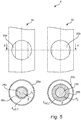
- fig 3 a portion of an example configuration of the probe arrangement 3 is schematically shown, including both the first transmission line probe 4a and the second transmission line probe 4b in a schematic side view, and in a cross-section view in the plane indicated by A-A' in fig 3 .
- the first transmission line probe 4a comprises a first transmission line probe conductor 24a, and a first dielectric enclosing structure 26a at least partly enclosing the first transmission line probe conductor 24a.
- the second transmission line probe 4b comprises a second transmission line probe conductor 24b, and a second dielectric enclosing structure 26b at least partly enclosing the second transmission line probe conductor 24b.
- the first dielectric enclosing structure 26a is provided in the form of a first dielectric sleeve that completely encloses the first probe conductor 24a.
- the first dielectric sleeve 26a has a first thickness d 1 , and a first relative dielectric constant ⁇ int,1 .
- the second dielectric enclosing structure 26b is provided in the form of a second dielectric sleeve that completely encloses the second probe conductor 24b.
- the second dielectric sleeve 26b has a second thickness d 2 , and a second relative dielectric constant ⁇ int,2 .
- the first dielectric sleeve 26a and the second dielectric sleeve 26b may be made of the same dielectric material, so that the first relative dielectric constant ⁇ int,1 and the second relative dielectric constant ⁇ int,2 are identical.
- the dielectric material may, for instance, be PTFE (polytetrafluoroethylene) having a relative dielectric constant of about 2.0 - 2.1.
- probe conductors of the transmission line probes 4a-b may be at least partly enclosed by different dielectric materials. Moreover, one of the probe conductors may be uncoated.
- the effective dielectric constant ⁇ eff of each of the transmission line probes 4a-b depends on the dielectric constant of the respective dielectric enclosing structure ⁇ int and the dielectric constant ⁇ ext of the surrounding medium 8 according to the following relation: ⁇ eff ⁇ 1 ⁇ ⁇ ext + 1 ⁇ ⁇ ⁇ int where ⁇ is a number between 0 and 1 which indicates the degree of coupling to the surrounding medium 8.
- the propagation velocity is inversely proportional to the square root of the effective dielectric constant ⁇ eff .
- the first coupling factor ⁇ 1 for the first transmission line probe 4a will depend on the first thickness d 1
- the second coupling factor ⁇ 2 for the second transmission line probe 4b will depend on the second thickness d 2 .
- fig 4 a diagram with the ratio between the propagation velocities for the first 4a and second 4b transmission line probes as a function of the dielectric constant ⁇ ext of the surrounding medium 8 is provided in fig 4 .
- the coupling factor ⁇ 1 for the first transmission line probe 4a is 0.75
- the coupling factor ⁇ 2 for the second transmission line probe 4b is 0.5.
- transmission line probe arrangement configurations can be used to achieve the desired different dependence of propagation velocity on dielectric constant ⁇ ext of the surrounding medium 8.
- One additional example of such a transmission line probe arrangement configuration will be described below with reference to fig 5 schematically showing a second exemplary transmission line probe arrangement configuration.
- a portion of a second example configuration of the probe arrangement 3 is schematically shown, including both the first transmission line probe 4a and the second transmission line probe 4b in a schematic side view, and in a cross-section view in the plane indicated by A-A' in fig 5 .
- the first transmission line probe 4a comprises a first transmission line probe conductor 24a, a first dielectric enclosing structure 26a at least partly enclosing the first transmission line probe conductor 24a, and a first shielding conductor 28a.
- the first shielding conductor 28a has openings 30a for allowing entry of product 6 (and the surrounding medium 8) to the space between the first transmission line probe conductor 24a and the first shielding conductor 28a.
- the second transmission line probe 4b comprises a second transmission line probe conductor 24b, and a second dielectric enclosing structure 26b at least partly enclosing the second transmission line probe conductor 24b, and a second shielding conductor 28b.
- the second shielding conductor 28b has openings 30b for allowing entry of product 6 (and the surrounding medium 8) to the space between the second transmission line probe conductor 24b and the second shielding conductor 28b.
- the first dielectric enclosing structure 26a is provided in the form of a first dielectric sleeve that completely encloses the first probe conductor 24a.
- the first dielectric sleeve 26a has a first thickness d 1 , and a first relative dielectric constant ⁇ int,1 .
- the second dielectric enclosing structure 26b is provided in the form of a second dielectric sleeve that completely encloses the second probe conductor 24b.
- the second dielectric sleeve 26b has a second thickness d 2 , and a second relative dielectric constant ⁇ int,2 .
- the first dielectric sleeve 26a and the second dielectric sleeve 26b may be made of the same dielectric material, so that the first relative dielectric constant ⁇ int,1 and the second relative dielectric constant ⁇ int,2 are identical.
- the dielectric material may, for instance, be PTFE (polytetrafluoroethylene) having a relative dielectric constant of about 2.0 - 2.1.
- the probe conductors of the transmission line probes 4a-b may be at least partly enclosed by different dielectric materials. Moreover, one of the probe conductors may be uncoated. Alternatively, or in combination, the inner surface of one or both of the shielding conductors 28a-b may be coated with dielectric material.
- a first step 101 an electromagnetic first transmit signal S T1 generated by the transceiver arrangement 10 is propagated towards the surface 7 of the product 6 using the first transmission line probe 4a, and an electromagnetic first surface echo signal S R1 resulting from reflection of the first transmit signal S T1 at the surface 7 is returned to the transceiver arrangement 10, where it is received.
- an electromagnetic second transmit signal S T2 generated by the transceiver arrangement 10 is propagated towards the surface 7 of the product 6 using the second transmission line probe 4b, and an electromagnetic second surface echo signal S R2 resulting from reflection of the second transmit signal S T2 at the surface 7 is returned to the transceiver arrangement 10, where it is received.
- step 103 the time-of-flight (or a value indicative of the time-of-flight) T 1 for the first transmit signal S T1 and the time-of-flight (or a value indicative of the time-of-flight) T 2 for the second transmit signal S T2 are determined.
- the dielectric constant ⁇ ext of the surrounding medium 8 is determined using the time-of-flight values T 1 , T 2 determined in step 103 and the known relation between the time-of-flight and the dielectric constant ⁇ ext of the surrounding medium 8 for the two transmission line probes 4a-b: ⁇ eff ⁇ 1 ⁇ ⁇ ext + 1 ⁇ ⁇ ⁇ int
- v prop v 0 ⁇ eff , where v 0 is the propagation velocity of electromagnetic signals along the probe in vacuum, the time-of-flight is proportional to ⁇ eff .
- the effective dielectric constant ⁇ eff can be determined, after which a DC-corrected (dielectric constant corrected) distance to the surface 7 of the product 6 is determined in step 105.
- the relationship between the propagation velocity (or time-of-flight) and the dielectric constant ⁇ ext of the surrounding medium 8 should be known for propagation along the first transmission line probe 4a and the second transmission line probe 4b.
- This relationship can, for example, be determined by simulations based on the configurations of the transmission line probes 4a-b (materials, dimensions etc) and/or measurements, and may be embodied as a mathematical formula or as a lookup table, or a combination of those. Such simulations and/or measurements will be well within the reach of those skilled in the art to carry out without undue burden.
- the radar level gauge system 1 comprises a first level gauging unit 40a and a second level gauging unit 40b.
- the first level gauging unit 40a comprises a first measurement electronics unit 2a and the above-described first transmission line probe 4a
- the second level gauging unit 40b comprises a second measurement electronics unit 2b and the above-described second transmission line probe 4b.
- the first measurement electronics unit 2a comprises a first transceiver (not shown in fig 7 ), and the second measurement electronics unit 2a comprises a second transceiver (not shown in fig 7 ).
- the processing circuitry of the radar level gauge system 1 is distributed among the first measurement electronics unit 2a, the second measurement electronics unit 2b, and a remote computer 42.
- the first level gauging unit 40a determines a first indication of the filling level, here indicated as a first ullage u 1 , based on signal propagation along the first transmission line probe 4a.
- the second level gauging unit 40b determines a second indication of the filling level, here indicated as a second ullage u 2 , based on signal propagation along the second transmission line probe 4b.
- the remote computer 42 comprised in the radar level gauge system 1 receives signals indicative of the first ullage u 1 and the second ullage u 2 , and determines a vapor compensated filling level based on the first ullage u 1 , the second ullage u 2 and known signal propagation properties of the first transmission line probe 4a and the second transmission line probe 4b.
Landscapes
- Physics & Mathematics (AREA)
- Engineering & Computer Science (AREA)
- Electromagnetism (AREA)
- Radar, Positioning & Navigation (AREA)
- Remote Sensing (AREA)
- General Physics & Mathematics (AREA)
- Computer Networks & Wireless Communication (AREA)
- Thermal Sciences (AREA)
- Fluid Mechanics (AREA)
- Measurement Of Levels Of Liquids Or Fluent Solid Materials (AREA)
Applications Claiming Priority (1)
| Application Number | Priority Date | Filing Date | Title |
|---|---|---|---|
| US15/281,344 US10295393B2 (en) | 2016-09-30 | 2016-09-30 | Guided wave radar level gauge system with dual transmission line probes for dielectric constant compensation |
Publications (2)
| Publication Number | Publication Date |
|---|---|
| EP3301412A1 true EP3301412A1 (de) | 2018-04-04 |
| EP3301412B1 EP3301412B1 (de) | 2020-08-05 |
Family
ID=59265563
Family Applications (1)
| Application Number | Title | Priority Date | Filing Date |
|---|---|---|---|
| EP17191012.8A Active EP3301412B1 (de) | 2016-09-30 | 2017-09-14 | Wellengeführtes radarfüllstandsmesssystem mit zwei übertragungsleitungssonden zur kompensation der dielektrizitätskonstante |
Country Status (3)
| Country | Link |
|---|---|
| US (1) | US10295393B2 (de) |
| EP (1) | EP3301412B1 (de) |
| CN (2) | CN206321306U (de) |
Families Citing this family (6)
| Publication number | Priority date | Publication date | Assignee | Title |
|---|---|---|---|---|
| US10295393B2 (en) * | 2016-09-30 | 2019-05-21 | Rosemount Tank Radar Ab | Guided wave radar level gauge system with dual transmission line probes for dielectric constant compensation |
| US10746585B2 (en) * | 2017-09-29 | 2020-08-18 | Rosemount Tank Radar Ab | Radar level gauging with wait state |
| US10816384B2 (en) * | 2017-10-31 | 2020-10-27 | Rosemount Tank Radar Ab | Radar level gauge system and method for interface measurement |
| WO2018131012A2 (en) * | 2018-04-13 | 2018-07-19 | Business Performance Advisors, Sa. | Method for tracking and tracing perishable cargo using a bidirectional smart device |
| EP3760984B1 (de) * | 2019-07-03 | 2023-08-30 | Rosemount Tank Radar AB | Übertragungsleitungssonde |
| WO2023250299A1 (en) * | 2022-06-24 | 2023-12-28 | Rosemount Inc. | Hygienic guided wave level measurement with sheath |
Citations (6)
| Publication number | Priority date | Publication date | Assignee | Title |
|---|---|---|---|---|
| US6121780A (en) * | 1996-10-07 | 2000-09-19 | Cruickshank; William T. | Material interface level sensing |
| US20070090992A1 (en) | 2005-10-21 | 2007-04-26 | Olov Edvardsson | Radar level gauge system and transmission line probe for use in such a system |
| US7525476B1 (en) | 2007-11-13 | 2009-04-28 | Rosemount Tank Radar Ab | System and method for filling level determination |
| US20120319891A1 (en) * | 2011-06-14 | 2012-12-20 | Olov Edvardsson | Guided wave radar level gauge system with dielectric constant compensation through multi-mode propagation |
| US20120324994A1 (en) * | 2010-12-16 | 2012-12-27 | Roland Welle | Determination of media characteristics in fill-level measuring |
| US20140085130A1 (en) * | 2012-09-26 | 2014-03-27 | Rosemount Tank Radar Ab | Guided wave radar level gauge system with dielectric constant compensation through multi-frequency propagation |
Family Cites Families (12)
| Publication number | Priority date | Publication date | Assignee | Title |
|---|---|---|---|---|
| DE19958584C1 (de) * | 1999-11-08 | 2001-02-01 | Krohne Sa | Füllstandmessgerät |
| US6445192B1 (en) * | 2000-04-04 | 2002-09-03 | Rosemount Inc. | Close proximity material interface detection for a microwave level transmitter |
| US6995706B2 (en) * | 2004-02-13 | 2006-02-07 | Saab Rosemount Tank Radar Ab | Method and an arrangement in a radar level gauging system |
| US7908920B2 (en) * | 2007-12-07 | 2011-03-22 | Robertshaw Controls Company | Velocity-of-propagation fluid level measurement method |
| US7634945B2 (en) * | 2007-12-13 | 2009-12-22 | Robertshaw Controls Company | Apparatus to water detection in a storage tank |
| EP2547987A4 (de) * | 2010-03-14 | 2014-05-14 | Titan Logix Corp | System und verfahren zur messung und dosierung einer enteisungsflüssigkeit aus einem tank mit einem refraktometermodul |
| CA2826049C (en) * | 2010-12-16 | 2016-09-06 | Vega Grieshaber Kg | Determination of media characteristics in fill-level measuring |
| US8701483B2 (en) * | 2010-12-16 | 2014-04-22 | Vega Grieshaber Kg | Device for emulsion measuring by means of a standpipe |
| US9612147B2 (en) * | 2014-02-10 | 2017-04-04 | Rosemount Tank Radar Ab | Radar level gauge system with multiple receiver branches |
| DE102014116763A1 (de) * | 2014-11-17 | 2016-05-19 | Endress + Hauser Gmbh + Co. Kg | Füllstandmessgerät |
| US10295393B2 (en) * | 2016-09-30 | 2019-05-21 | Rosemount Tank Radar Ab | Guided wave radar level gauge system with dual transmission line probes for dielectric constant compensation |
| US10184820B2 (en) * | 2016-09-30 | 2019-01-22 | Rosemount Tank Radar Ab | Guided wave radar level gauge system for interface measurement |
-
2016
- 2016-09-30 US US15/281,344 patent/US10295393B2/en active Active
- 2016-11-29 CN CN201621298255.1U patent/CN206321306U/zh active Active
- 2016-11-29 CN CN201611077444.0A patent/CN107884033B/zh active Active
-
2017
- 2017-09-14 EP EP17191012.8A patent/EP3301412B1/de active Active
Patent Citations (6)
| Publication number | Priority date | Publication date | Assignee | Title |
|---|---|---|---|---|
| US6121780A (en) * | 1996-10-07 | 2000-09-19 | Cruickshank; William T. | Material interface level sensing |
| US20070090992A1 (en) | 2005-10-21 | 2007-04-26 | Olov Edvardsson | Radar level gauge system and transmission line probe for use in such a system |
| US7525476B1 (en) | 2007-11-13 | 2009-04-28 | Rosemount Tank Radar Ab | System and method for filling level determination |
| US20120324994A1 (en) * | 2010-12-16 | 2012-12-27 | Roland Welle | Determination of media characteristics in fill-level measuring |
| US20120319891A1 (en) * | 2011-06-14 | 2012-12-20 | Olov Edvardsson | Guided wave radar level gauge system with dielectric constant compensation through multi-mode propagation |
| US20140085130A1 (en) * | 2012-09-26 | 2014-03-27 | Rosemount Tank Radar Ab | Guided wave radar level gauge system with dielectric constant compensation through multi-frequency propagation |
Also Published As
| Publication number | Publication date |
|---|---|
| EP3301412B1 (de) | 2020-08-05 |
| CN107884033B (zh) | 2021-01-01 |
| US20180094963A1 (en) | 2018-04-05 |
| CN107884033A (zh) | 2018-04-06 |
| CN206321306U (zh) | 2017-07-11 |
| US10295393B2 (en) | 2019-05-21 |
Similar Documents
| Publication | Publication Date | Title |
|---|---|---|
| EP3301412B1 (de) | Wellengeführtes radarfüllstandsmesssystem mit zwei übertragungsleitungssonden zur kompensation der dielektrizitätskonstante | |
| EP2721378B1 (de) | Wellenleiter-radarfüllstandsmesssystem mit kompensation der dielektrischen konstante durch mehrmodenausbreitung | |
| EP2359102B1 (de) | System und verfahren zur bestimmung des füllstandes | |
| US9228877B2 (en) | Guided wave radar level gauge system with dielectric constant compensation through multi-frequency propagation | |
| US7924216B2 (en) | Method of determining a disturbance echo profile for a radar level gauge system | |
| EP2490040B1 (de) | Einzelleitersonde-GWR-System mit reduzierter Reflexion am Düsenende | |
| CN107884035B (zh) | 雷达料位计系统以及确定储罐中的界面料位的方法 | |
| JPH06201435A (ja) | 液体の充填レベル測定方法 | |
| KR20080023170A (ko) | 레이더 수위 측정 | |
| US20150168202A1 (en) | Fill-level measuring device and apparatus for determining the dielectric constant | |
| EP2972469A1 (de) | Radarpegelmessung mit signalteilung | |
| CN108225483B (zh) | 罐布置 | |
| EP3704451B1 (de) | Radarpegelmesssystem und verfahren zur schnittstellenmessung | |
| EP3857183B1 (de) | System und verfahren zur bestimmung einer höhen- und dichteverteilung | |
| EP3405757B1 (de) | Radarpegelmesssystem und verfahren mit signalausbreitungswegmodellierung |
Legal Events
| Date | Code | Title | Description |
|---|---|---|---|
| PUAI | Public reference made under article 153(3) epc to a published international application that has entered the european phase |
Free format text: ORIGINAL CODE: 0009012 |
|
| STAA | Information on the status of an ep patent application or granted ep patent |
Free format text: STATUS: THE APPLICATION HAS BEEN PUBLISHED |
|
| AK | Designated contracting states |
Kind code of ref document: A1 Designated state(s): AL AT BE BG CH CY CZ DE DK EE ES FI FR GB GR HR HU IE IS IT LI LT LU LV MC MK MT NL NO PL PT RO RS SE SI SK SM TR |
|
| AX | Request for extension of the european patent |
Extension state: BA ME |
|
| STAA | Information on the status of an ep patent application or granted ep patent |
Free format text: STATUS: REQUEST FOR EXAMINATION WAS MADE |
|
| 17P | Request for examination filed |
Effective date: 20180910 |
|
| RBV | Designated contracting states (corrected) |
Designated state(s): AL AT BE BG CH CY CZ DE DK EE ES FI FR GB GR HR HU IE IS IT LI LT LU LV MC MK MT NL NO PL PT RO RS SE SI SK SM TR |
|
| STAA | Information on the status of an ep patent application or granted ep patent |
Free format text: STATUS: EXAMINATION IS IN PROGRESS |
|
| 17Q | First examination report despatched |
Effective date: 20190521 |
|
| GRAP | Despatch of communication of intention to grant a patent |
Free format text: ORIGINAL CODE: EPIDOSNIGR1 |
|
| STAA | Information on the status of an ep patent application or granted ep patent |
Free format text: STATUS: GRANT OF PATENT IS INTENDED |
|
| RIC1 | Information provided on ipc code assigned before grant |
Ipc: G01F 23/284 20060101AFI20200227BHEP Ipc: G01S 13/88 20060101ALI20200227BHEP Ipc: G01S 7/03 20060101ALI20200227BHEP |
|
| INTG | Intention to grant announced |
Effective date: 20200326 |
|
| GRAS | Grant fee paid |
Free format text: ORIGINAL CODE: EPIDOSNIGR3 |
|
| GRAA | (expected) grant |
Free format text: ORIGINAL CODE: 0009210 |
|
| STAA | Information on the status of an ep patent application or granted ep patent |
Free format text: STATUS: THE PATENT HAS BEEN GRANTED |
|
| AK | Designated contracting states |
Kind code of ref document: B1 Designated state(s): AL AT BE BG CH CY CZ DE DK EE ES FI FR GB GR HR HU IE IS IT LI LT LU LV MC MK MT NL NO PL PT RO RS SE SI SK SM TR |
|
| REG | Reference to a national code |
Ref country code: GB Ref legal event code: FG4D |
|
| REG | Reference to a national code |
Ref country code: CH Ref legal event code: EP |
|
| REG | Reference to a national code |
Ref country code: AT Ref legal event code: REF Ref document number: 1299353 Country of ref document: AT Kind code of ref document: T Effective date: 20200815 |
|
| REG | Reference to a national code |
Ref country code: IE Ref legal event code: FG4D |
|
| REG | Reference to a national code |
Ref country code: DE Ref legal event code: R096 Ref document number: 602017020917 Country of ref document: DE |
|
| REG | Reference to a national code |
Ref country code: CH Ref legal event code: NV Representative=s name: OFFICE ERNEST T. FREYLINGER S.A., CH |
|
| REG | Reference to a national code |
Ref country code: LT Ref legal event code: MG4D |
|
| REG | Reference to a national code |
Ref country code: NL Ref legal event code: MP Effective date: 20200805 |
|
| REG | Reference to a national code |
Ref country code: AT Ref legal event code: MK05 Ref document number: 1299353 Country of ref document: AT Kind code of ref document: T Effective date: 20200805 |
|
| PG25 | Lapsed in a contracting state [announced via postgrant information from national office to epo] |
Ref country code: ES Free format text: LAPSE BECAUSE OF FAILURE TO SUBMIT A TRANSLATION OF THE DESCRIPTION OR TO PAY THE FEE WITHIN THE PRESCRIBED TIME-LIMIT Effective date: 20200805 Ref country code: GR Free format text: LAPSE BECAUSE OF FAILURE TO SUBMIT A TRANSLATION OF THE DESCRIPTION OR TO PAY THE FEE WITHIN THE PRESCRIBED TIME-LIMIT Effective date: 20201106 Ref country code: BG Free format text: LAPSE BECAUSE OF FAILURE TO SUBMIT A TRANSLATION OF THE DESCRIPTION OR TO PAY THE FEE WITHIN THE PRESCRIBED TIME-LIMIT Effective date: 20201105 Ref country code: SE Free format text: LAPSE BECAUSE OF FAILURE TO SUBMIT A TRANSLATION OF THE DESCRIPTION OR TO PAY THE FEE WITHIN THE PRESCRIBED TIME-LIMIT Effective date: 20200805 Ref country code: HR Free format text: LAPSE BECAUSE OF FAILURE TO SUBMIT A TRANSLATION OF THE DESCRIPTION OR TO PAY THE FEE WITHIN THE PRESCRIBED TIME-LIMIT Effective date: 20200805 Ref country code: LT Free format text: LAPSE BECAUSE OF FAILURE TO SUBMIT A TRANSLATION OF THE DESCRIPTION OR TO PAY THE FEE WITHIN THE PRESCRIBED TIME-LIMIT Effective date: 20200805 Ref country code: PT Free format text: LAPSE BECAUSE OF FAILURE TO SUBMIT A TRANSLATION OF THE DESCRIPTION OR TO PAY THE FEE WITHIN THE PRESCRIBED TIME-LIMIT Effective date: 20201207 Ref country code: FI Free format text: LAPSE BECAUSE OF FAILURE TO SUBMIT A TRANSLATION OF THE DESCRIPTION OR TO PAY THE FEE WITHIN THE PRESCRIBED TIME-LIMIT Effective date: 20200805 Ref country code: NO Free format text: LAPSE BECAUSE OF FAILURE TO SUBMIT A TRANSLATION OF THE DESCRIPTION OR TO PAY THE FEE WITHIN THE PRESCRIBED TIME-LIMIT Effective date: 20201105 Ref country code: AT Free format text: LAPSE BECAUSE OF FAILURE TO SUBMIT A TRANSLATION OF THE DESCRIPTION OR TO PAY THE FEE WITHIN THE PRESCRIBED TIME-LIMIT Effective date: 20200805 |
|
| PG25 | Lapsed in a contracting state [announced via postgrant information from national office to epo] |
Ref country code: NL Free format text: LAPSE BECAUSE OF FAILURE TO SUBMIT A TRANSLATION OF THE DESCRIPTION OR TO PAY THE FEE WITHIN THE PRESCRIBED TIME-LIMIT Effective date: 20200805 Ref country code: PL Free format text: LAPSE BECAUSE OF FAILURE TO SUBMIT A TRANSLATION OF THE DESCRIPTION OR TO PAY THE FEE WITHIN THE PRESCRIBED TIME-LIMIT Effective date: 20200805 Ref country code: RS Free format text: LAPSE BECAUSE OF FAILURE TO SUBMIT A TRANSLATION OF THE DESCRIPTION OR TO PAY THE FEE WITHIN THE PRESCRIBED TIME-LIMIT Effective date: 20200805 Ref country code: LV Free format text: LAPSE BECAUSE OF FAILURE TO SUBMIT A TRANSLATION OF THE DESCRIPTION OR TO PAY THE FEE WITHIN THE PRESCRIBED TIME-LIMIT Effective date: 20200805 Ref country code: IS Free format text: LAPSE BECAUSE OF FAILURE TO SUBMIT A TRANSLATION OF THE DESCRIPTION OR TO PAY THE FEE WITHIN THE PRESCRIBED TIME-LIMIT Effective date: 20201205 |
|
| PG25 | Lapsed in a contracting state [announced via postgrant information from national office to epo] |
Ref country code: EE Free format text: LAPSE BECAUSE OF FAILURE TO SUBMIT A TRANSLATION OF THE DESCRIPTION OR TO PAY THE FEE WITHIN THE PRESCRIBED TIME-LIMIT Effective date: 20200805 Ref country code: SM Free format text: LAPSE BECAUSE OF FAILURE TO SUBMIT A TRANSLATION OF THE DESCRIPTION OR TO PAY THE FEE WITHIN THE PRESCRIBED TIME-LIMIT Effective date: 20200805 Ref country code: RO Free format text: LAPSE BECAUSE OF FAILURE TO SUBMIT A TRANSLATION OF THE DESCRIPTION OR TO PAY THE FEE WITHIN THE PRESCRIBED TIME-LIMIT Effective date: 20200805 Ref country code: CZ Free format text: LAPSE BECAUSE OF FAILURE TO SUBMIT A TRANSLATION OF THE DESCRIPTION OR TO PAY THE FEE WITHIN THE PRESCRIBED TIME-LIMIT Effective date: 20200805 Ref country code: DK Free format text: LAPSE BECAUSE OF FAILURE TO SUBMIT A TRANSLATION OF THE DESCRIPTION OR TO PAY THE FEE WITHIN THE PRESCRIBED TIME-LIMIT Effective date: 20200805 |
|
| REG | Reference to a national code |
Ref country code: DE Ref legal event code: R097 Ref document number: 602017020917 Country of ref document: DE |
|
| PG25 | Lapsed in a contracting state [announced via postgrant information from national office to epo] |
Ref country code: AL Free format text: LAPSE BECAUSE OF FAILURE TO SUBMIT A TRANSLATION OF THE DESCRIPTION OR TO PAY THE FEE WITHIN THE PRESCRIBED TIME-LIMIT Effective date: 20200805 Ref country code: MC Free format text: LAPSE BECAUSE OF FAILURE TO SUBMIT A TRANSLATION OF THE DESCRIPTION OR TO PAY THE FEE WITHIN THE PRESCRIBED TIME-LIMIT Effective date: 20200805 |
|
| PLBE | No opposition filed within time limit |
Free format text: ORIGINAL CODE: 0009261 |
|
| STAA | Information on the status of an ep patent application or granted ep patent |
Free format text: STATUS: NO OPPOSITION FILED WITHIN TIME LIMIT |
|
| REG | Reference to a national code |
Ref country code: BE Ref legal event code: MM Effective date: 20200930 |
|
| PG25 | Lapsed in a contracting state [announced via postgrant information from national office to epo] |
Ref country code: LU Free format text: LAPSE BECAUSE OF NON-PAYMENT OF DUE FEES Effective date: 20200914 Ref country code: SK Free format text: LAPSE BECAUSE OF FAILURE TO SUBMIT A TRANSLATION OF THE DESCRIPTION OR TO PAY THE FEE WITHIN THE PRESCRIBED TIME-LIMIT Effective date: 20200805 |
|
| 26N | No opposition filed |
Effective date: 20210507 |
|
| PG25 | Lapsed in a contracting state [announced via postgrant information from national office to epo] |
Ref country code: IT Free format text: LAPSE BECAUSE OF FAILURE TO SUBMIT A TRANSLATION OF THE DESCRIPTION OR TO PAY THE FEE WITHIN THE PRESCRIBED TIME-LIMIT Effective date: 20200805 Ref country code: FR Free format text: LAPSE BECAUSE OF NON-PAYMENT OF DUE FEES Effective date: 20201005 |
|
| PG25 | Lapsed in a contracting state [announced via postgrant information from national office to epo] |
Ref country code: SI Free format text: LAPSE BECAUSE OF FAILURE TO SUBMIT A TRANSLATION OF THE DESCRIPTION OR TO PAY THE FEE WITHIN THE PRESCRIBED TIME-LIMIT Effective date: 20200805 Ref country code: IE Free format text: LAPSE BECAUSE OF NON-PAYMENT OF DUE FEES Effective date: 20200914 Ref country code: BE Free format text: LAPSE BECAUSE OF NON-PAYMENT OF DUE FEES Effective date: 20200930 |
|
| GBPC | Gb: european patent ceased through non-payment of renewal fee |
Effective date: 20210914 |
|
| PG25 | Lapsed in a contracting state [announced via postgrant information from national office to epo] |
Ref country code: TR Free format text: LAPSE BECAUSE OF FAILURE TO SUBMIT A TRANSLATION OF THE DESCRIPTION OR TO PAY THE FEE WITHIN THE PRESCRIBED TIME-LIMIT Effective date: 20200805 Ref country code: MT Free format text: LAPSE BECAUSE OF FAILURE TO SUBMIT A TRANSLATION OF THE DESCRIPTION OR TO PAY THE FEE WITHIN THE PRESCRIBED TIME-LIMIT Effective date: 20200805 Ref country code: CY Free format text: LAPSE BECAUSE OF FAILURE TO SUBMIT A TRANSLATION OF THE DESCRIPTION OR TO PAY THE FEE WITHIN THE PRESCRIBED TIME-LIMIT Effective date: 20200805 |
|
| PG25 | Lapsed in a contracting state [announced via postgrant information from national office to epo] |
Ref country code: MK Free format text: LAPSE BECAUSE OF FAILURE TO SUBMIT A TRANSLATION OF THE DESCRIPTION OR TO PAY THE FEE WITHIN THE PRESCRIBED TIME-LIMIT Effective date: 20200805 |
|
| PG25 | Lapsed in a contracting state [announced via postgrant information from national office to epo] |
Ref country code: GB Free format text: LAPSE BECAUSE OF NON-PAYMENT OF DUE FEES Effective date: 20210914 |
|
| PGFP | Annual fee paid to national office [announced via postgrant information from national office to epo] |
Ref country code: DE Payment date: 20230822 Year of fee payment: 7 |
|
| PGFP | Annual fee paid to national office [announced via postgrant information from national office to epo] |
Ref country code: CH Payment date: 20231001 Year of fee payment: 7 |