EP3301411B1 - Measuring pipe unit and coriolis mass flow meter - Google Patents
Measuring pipe unit and coriolis mass flow meter Download PDFInfo
- Publication number
- EP3301411B1 EP3301411B1 EP17193714.7A EP17193714A EP3301411B1 EP 3301411 B1 EP3301411 B1 EP 3301411B1 EP 17193714 A EP17193714 A EP 17193714A EP 3301411 B1 EP3301411 B1 EP 3301411B1
- Authority
- EP
- European Patent Office
- Prior art keywords
- measuring tube
- transition piece
- section
- cross
- transition
- Prior art date
- Legal status (The legal status is an assumption and is not a legal conclusion. Google has not performed a legal analysis and makes no representation as to the accuracy of the status listed.)
- Active
Links
- 230000007704 transition Effects 0.000 claims description 155
- 238000000034 method Methods 0.000 claims description 6
- 238000005259 measurement Methods 0.000 claims description 5
- 230000008569 process Effects 0.000 claims description 4
- 238000000149 argon plasma sintering Methods 0.000 claims description 2
- 238000010146 3D printing Methods 0.000 claims 1
- 239000012530 fluid Substances 0.000 description 19
- 230000008901 benefit Effects 0.000 description 7
- 238000004519 manufacturing process Methods 0.000 description 4
- 239000000463 material Substances 0.000 description 4
- 230000000717 retained effect Effects 0.000 description 3
- 238000011156 evaluation Methods 0.000 description 2
- 230000015572 biosynthetic process Effects 0.000 description 1
- 230000008878 coupling Effects 0.000 description 1
- 238000010168 coupling process Methods 0.000 description 1
- 238000005859 coupling reaction Methods 0.000 description 1
- 230000001419 dependent effect Effects 0.000 description 1
- 230000005284 excitation Effects 0.000 description 1
- 230000002349 favourable effect Effects 0.000 description 1
- 239000007789 gas Substances 0.000 description 1
- 239000007788 liquid Substances 0.000 description 1
- 230000010355 oscillation Effects 0.000 description 1
- 230000009467 reduction Effects 0.000 description 1
Images


Classifications
-
- G—PHYSICS
- G01—MEASURING; TESTING
- G01F—MEASURING VOLUME, VOLUME FLOW, MASS FLOW OR LIQUID LEVEL; METERING BY VOLUME
- G01F1/00—Measuring the volume flow or mass flow of fluid or fluent solid material wherein the fluid passes through a meter in a continuous flow
- G01F1/76—Devices for measuring mass flow of a fluid or a fluent solid material
- G01F1/78—Direct mass flowmeters
- G01F1/80—Direct mass flowmeters operating by measuring pressure, force, momentum, or frequency of a fluid flow to which a rotational movement has been imparted
- G01F1/84—Coriolis or gyroscopic mass flowmeters
- G01F1/8409—Coriolis or gyroscopic mass flowmeters constructional details
- G01F1/8413—Coriolis or gyroscopic mass flowmeters constructional details means for influencing the flowmeter's motional or vibrational behaviour, e.g., conduit support or fixing means, or conduit attachments
-
- G—PHYSICS
- G01—MEASURING; TESTING
- G01F—MEASURING VOLUME, VOLUME FLOW, MASS FLOW OR LIQUID LEVEL; METERING BY VOLUME
- G01F1/00—Measuring the volume flow or mass flow of fluid or fluent solid material wherein the fluid passes through a meter in a continuous flow
- G01F1/76—Devices for measuring mass flow of a fluid or a fluent solid material
- G01F1/78—Direct mass flowmeters
- G01F1/80—Direct mass flowmeters operating by measuring pressure, force, momentum, or frequency of a fluid flow to which a rotational movement has been imparted
- G01F1/84—Coriolis or gyroscopic mass flowmeters
- G01F1/8404—Coriolis or gyroscopic mass flowmeters details of flowmeter manufacturing methods
-
- G—PHYSICS
- G01—MEASURING; TESTING
- G01F—MEASURING VOLUME, VOLUME FLOW, MASS FLOW OR LIQUID LEVEL; METERING BY VOLUME
- G01F1/00—Measuring the volume flow or mass flow of fluid or fluent solid material wherein the fluid passes through a meter in a continuous flow
- G01F1/76—Devices for measuring mass flow of a fluid or a fluent solid material
- G01F1/78—Direct mass flowmeters
- G01F1/80—Direct mass flowmeters operating by measuring pressure, force, momentum, or frequency of a fluid flow to which a rotational movement has been imparted
- G01F1/84—Coriolis or gyroscopic mass flowmeters
- G01F1/845—Coriolis or gyroscopic mass flowmeters arrangements of measuring means, e.g., of measuring conduits
- G01F1/8468—Coriolis or gyroscopic mass flowmeters arrangements of measuring means, e.g., of measuring conduits vibrating measuring conduits
- G01F1/849—Coriolis or gyroscopic mass flowmeters arrangements of measuring means, e.g., of measuring conduits vibrating measuring conduits having straight measuring conduits
- G01F1/8495—Coriolis or gyroscopic mass flowmeters arrangements of measuring means, e.g., of measuring conduits vibrating measuring conduits having straight measuring conduits with multiple measuring conduits
Definitions
- the invention is based on a measuring tube unit for use in a Coriolis mass flow meter with an inlet end and an outlet end, comprising at least two measuring tubes and at least two transition pieces, one transition piece being arranged on a measuring tube at the inlet end, each measuring tube having a measuring tube cross section and each Transition piece has an adapter cross section at the inlet.
- the invention is based on a Coriolis mass flow meter with at least one measuring tube unit with an inlet end and an outlet end, the measuring tube unit having at least two measuring tubes and at least two transition pieces, each with a transition piece being arranged on a measuring tube at the inlet end of the measuring tube unit, each of which Measuring tube has a measuring tube cross section and each transition piece has a transition piece cross section at the inlet.
- Coriolis mass flow meters are suitable for determining the mass flow of gases and / or liquids in a particularly wide range of applications.
- To determine the mass flow rate the fact that the Coriolis force acts on the fluid to be measured when it flows through a pipe set in vibration is used.
- Coriolis mass flowmeters generally have at least one measuring tube through which a fluid flows, an oscillation generator which sets the measuring tube in vibration, and two vibration sensors, the vibration sensors being arranged at the inlet end and at the outlet end of the measuring tube. If the measuring tube is set in vibration by the vibration generator during operation, the vibration sensors of the vibration tube are detected on the inlet side and on the outlet side. If a fluid also flows through the measuring tube, the Coriolis force causes an additional force on the measuring tube. This can be measured as the phase difference between the inlet-side and the outlet-side vibration. The phase difference is proportional to the mass flow of the fluid.
- the reference point is always the flow direction of the one to be detected Fluids in the operation of the flow meter. Accordingly, the inlet end corresponds to the side of the measuring tube unit through which the fluid flows into the measuring tube unit, and the outlet end consequently corresponds to the side through which the fluid leaves the measuring tube unit.
- a particularly simple embodiment has only a single straight measuring tube.
- a further embodiment has a double tube arrangement in which the measuring tubes are excited to oscillate in opposite directions to one another.
- pipe bends for example in the form of U-tubes, are used, with designs with a single pipe bend as well as with a double pipe arrangement also being known.
- Coriolis mass flow meters are installed in existing piping systems and connected to the piping via a flange connection. If the Coriolis mass flow meter has more than one measuring tube, for example two or four measuring tubes, the fluid flow to be measured must preferably be distributed evenly over the individual measuring tubes via a flow divider.
- a holder for the housing of the flow meter which is arranged at least at the inlet end and preferably also at the outlet end of the measuring tubes, and which is at the same time designed as a flow divider.
- the holder has a connection area to a pipeline. This connection area has openings, each opening being connected to a measuring tube, for example by a welded connection.
- each holder is suitable for exactly one measuring setup, ie a certain number of measuring tubes. Different measurement setups therefore require a variety of different brackets. However, since the design of a corresponding holder is very complex, the effort to manufacture and maintain this large number of holders is particularly high.
- the above-described embodiment from the prior art has the disadvantage that the fluid to be measured has contact with at least two materials within the flow measuring device, namely the material of the holder and the material of the measuring tubes.
- the publication EP 2 650 656 A1 discloses a Coriolis mass flow meter which has an additional transition piece and a connecting piece for connecting the two measuring tubes to a pipeline, the transition piece and the connecting piece being produced from one workpiece.
- a mass flow meter, which has a corresponding transition and connection piece, also has the disadvantages set out above.
- US 5,540,106 A discloses a measuring tube unit for use in a Coriolis mass flow meter.
- US 2002/139199 A1 discloses a measuring tube unit comprising two measuring tubes and a flow divider.
- DE 10 2014 119073 A1 discloses a vibration type sensor with a housing module.
- the object is achieved by the above-mentioned measuring tube unit in that the transition piece is designed in one piece with the associated measuring tube and in that the cross-section of the transition piece differs in shape and / or size from the associated measuring tube cross-section, the measuring tubes are arranged and aligned in such a way that the transition piece cross-sections form an overall cross-section and thus a flow divider.
- each measuring tube is designed in one piece with a transition piece, the entirety of the transition pieces making it possible to connect a plurality of measuring tubes to a pipeline.
- Each transition piece is designed and arranged during operation in such a way that it conducts part of the fluid flow from the one pipeline into the associated measuring tube.
- the transition piece is a kind of inlet funnel into the associated measuring tube.
- the transition piece is designed in such a way that the cross-section of the transition piece differs in shape and / or size from the cross-section of the measuring tube.
- the transition piece in his Design on the one hand adapted to the cross-section of the one pipeline and at the same time to the measuring setup, in detail to the number of measuring pipes.
- the shape of the transition piece cross section is retained and the transition piece cross section only differs in size from the measuring tube cross section.
- the size of the transition piece cross section is retained and the transition piece cross section only differs in shape from the measuring tube cross section
- the cross-section of the transition piece usually deviates in shape and size from the cross-section of the measuring tube.
- the measuring tubes are arranged and aligned according to the invention in such a way that the transition piece cross sections of the measuring tubes form an overall cross section and thus a flow divider.
- This overall cross section can lie in one plane, but alternatively the individual transition cross sections can also form an angle with one another that is smaller or larger than 180 °.
- a flow divider is formed by the formation of the overall cross section, which advantageously means that an additional component for dividing the fluid flow to be measured can be dispensed with.
- a measuring tube unit according to the invention makes it possible, in particular, to dispense with the production of a large number of different brackets, as the transition from a pipeline to the at least two measuring tubes is provided by the measuring tube unit itself.
- the measuring tube unit according to the invention has the advantage that the fluid to be measured is in contact with only one material during operation in the flow measuring device.
- the overall cross section is circular.
- the diameter of the total cross section particularly preferably corresponds essentially to the diameter of the pipeline to be connected.
- the diameter of the total cross section essentially corresponding to the diameter of the one pipeline, particularly favorable. It is also advantageous if the shape of the overall cross section deviates slightly from a circular shape. It is conceivable, for example, if the overall cross-section has the shape of a cloverleaf or a square or represents a connection of circular segments.
- transition piece cross sections have the same shape and the same size. This configuration ensures that the fluid flow is divided evenly between the individual measuring tubes during operation.
- the transition piece cross section of at least one transition piece has the shape of a semicircle or a quarter circle or a segment of a circle.
- the shape of the cross-section of the transition piece is particularly dependent on the number of measuring tubes. If the measuring tube unit has two measuring tubes, each with a transition piece, the transition piece cross section of each transition piece is preferably semicircular. If the measuring tube unit has four measuring tubes, each with a transition piece, then the transition piece cross section of each transition piece is preferably quarter-circle-shaped. In addition, it is also advantageous if the transition piece cross sections have the shape of a circular segment or a circular section or a triangle.
- the area of the transition piece cross section is larger than the area of the associated measuring tube cross section and if the transition piece has a diameter reduction when viewed in the flow direction.
- This configuration of the measuring tube unit is used, for example, if the cross-sectional area of the one pipeline is larger than the measuring tube cross section. This is particularly the case if the measuring tube unit has at least two measuring tubes or at least four measuring tubes.
- the area of the transition piece cross section is smaller than the area of the associated measuring tube cross section and if the transition piece has an increase in diameter when viewed in the flow direction.
- This configuration is used in particular if the cross-sectional area of one pipe is smaller than the measuring pipe cross-section.
- a further embodiment of the measuring tube unit has at least two further transition pieces, one transition piece each being arranged on a measuring tube at the outlet end, each transition piece having a transition piece cross section at the outlet, the transition piece being designed in one piece with the associated measuring tube and the transition piece cross section being in its shape and / or its size deviates from the associated measuring tube cross section, the measuring tubes being arranged in such a way that the transition piece cross sections form an overall cross section.
- This embodiment has the advantage that not only on the inlet side but also on the outlet side, a fluidically advantageous transition from at least two measuring tubes to a pipeline can be ensured.
- transition piece on the outlet side in particular the cross section of the transition piece, reference is made to the features of the transition pieces arranged on the inlet side. All the configurations described below also relate to transition pieces arranged on the inlet side and on the outlet side.
- the outlet-side transition pieces are particularly preferably configured identically with the transition pieces arranged at the inlet end. Alternatively, they can also differ in particular in the shape of the transition piece cross section from the transition pieces arranged on the inlet side.
- the transition piece and the associated measuring tube are made from one workpiece.
- the transition piece is particularly preferably a deformation of the end geometry of the measuring tube, the wall thickness of the measuring tube preferably being retained.
- the transition piece and the associated measuring tube are preferably made from one tube.
- the transition piece or the unit consisting of transition piece and measuring tube is produced, for example, by a mechanical forming process. This has the advantage that the transition piece or the unit consisting of transition piece and measuring tube has particularly flowing transitions.
- the transition piece or the unit comprising the transition piece and measuring tube can be produced by means of high-pressure forming, in particular by means of internal high-pressure forming.
- This has the advantage that due to the particularly high precision of the method, the transition piece or the unit consisting of the transition piece and measuring tube also has a particularly high precision with regard to its shape and its dimension.
- the transition piece or the unit consisting of transition piece and measuring tube can also be produced by means of laser sintering or by means of a 3-D printing process.
- the advantage of these methods is that any geometry can be created, so that the geometry of the transition piece can be of any complexity.
- the transition piece or the unit consisting of the transition piece and measuring tube also has a particularly high degree of precision with regard to its shape and dimensions.
- the transition pieces adjoin one another at the end in common contact contours and are tightly connected to one another in the contact contours. This configuration ensures that the fluid to be measured cannot run past the transition pieces into the flow meter during operation.
- transition pieces are preferably connected to one another in the area of the contact contours in a form-fitting, force-fitting and / or material-fitting manner.
- the object set forth at the outset is achieved by the Coriolis mass flow measuring device mentioned at the outset in that the transition piece is designed in one piece with the associated measuring tube and in that the cross-section of the transition piece differs in shape and / or in size from the associated measuring tube cross section, wherein the measuring tubes are arranged and aligned in such a way that the transition piece cross sections form an overall cross section and thus a flow divider.
- the measuring device has one of the measuring tube units described above.
- the statements made for the respective measuring tube unit also apply to a Coriolis mass flow meter that has such a measuring tube unit.
- At least one holder with a receptacle for the measuring tube unit is present, the receptacle sealingly fitting with the measuring tube unit.
- Fig. 1 is shown an arrangement of two measuring tubes 5 and a holder 11 for receiving the housing, not shown here, of a Coriolis mass flow meter from the state of the art.
- the arrangement is suitable for connecting two measuring tubes 5 to a pipeline.
- the holder 11 has a connection area 17, the connection area 17 as a flow divider during operation dividing the fluid flow evenly between the measuring tubes 5.
- a disadvantage of the arrangement shown is that the holder 11, which also serves as a connection to the pipeline and as a flow divider, is adapted to a measuring setup, here consisting of two measuring tubes 5. Different measurement setups therefore require different brackets 11, the manufacture of which is, however, relatively complex due to their complexity.
- Fig. 2 also shows an arrangement for connecting two measuring tubes 5 to a pipeline via a holder 11 from the prior art in a sectional view.
- the connection area 17 is designed such that, as a flow divider during operation, it divides the fluid flow that flows through the connected pipeline (not shown here) onto the measuring tubes 5.
- the measuring tubes 5 are connected to the connection area 17 via a welded connection.
- the 3 and 4 each show exemplary embodiments of a measuring tube 5 and a transition piece 6a, the transition piece 6a in each case being designed in one piece with the measuring tube 5.
- the measuring tube 5 has a circular measuring tube cross section 8 and the transition piece 6a at the inlet has a transition piece cross section 9a.
- Transition piece cross section 9a shown is semicircular, in the course of the transition piece 6a this has a transition to the circular measuring tube cross section 8 of the measuring tube 5.
- This in Fig. 3 The measuring tube 5 shown is therefore suitable for use in a measuring tube unit 1 consisting of two measuring tubes 5.
- the in Fig. 4 Transition piece cross section 9a shown is configured in a quarter circle and likewise has a transition to the circular measuring tube cross section 8 of the measuring tube 5 in the course of the transition piece 6a.
- This in Fig. 4 The measuring tube 5 shown is thus suitable for use in a measuring tube unit 1 consisting of four measuring tubes 5.
- transition piece cross sections 9a and total cross sections 10a are shown.
- the transition piece cross sections 9a are designed semi-circular. Together, the transition piece cross sections 9a form an overall circular cross section 10a.
- Transitional cross sections 9a shown each have the shape of a quarter circle, the total cross section 10a also being circular.
- Transition piece cross sections 9a shown are triangular and together form an overall cross section 10a in the form of a square.
- Transition piece cross sections 9a shown have the shape of a circle segment, the total cross section 10a deviating slightly from the circular shape.
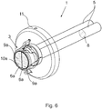
- Fig. 6 shows a first embodiment of a measuring tube unit 1 according to the invention for use in a Coriolis mass flow meter 2 with an inlet end 3 and an outlet end 4, not shown here, with two measuring tubes 5 and two transition pieces 6a, each measuring tube having a measuring tube cross section 8 and each transition piece 6a at the inlet have a transition piece cross section 9a.
- the transition pieces 6a are designed in one piece with the associated measuring tube 5; in the exemplary embodiment shown, they are made from one workpiece.
- the measuring tubes 5 are arranged in such a way that the transition piece cross-sections 9a have a circular overall cross-section 10a, which is identical to the pipeline cross-section of the pipeline not shown here.
- the two transition pieces 6a serve on the one hand to connect the two measuring tubes 5 to a pipeline and, at the same time, evenly distribute the fluid flow flowing through the pipeline to the measuring tubes 5 during operation.
- the use of a measuring tube unit 1 thus has the advantage that the holder 11 does not have to meet any special requirements with regard to the measuring setup.
- the bracket 11, which is complex to manufacture, can be used particularly flexibly.
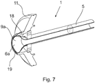
- Fig. 7 shows a sectional view of the first exemplary embodiment of the measuring tube unit 1 according to the invention, a measuring tube 5 and a transition piece 6a having a semicircular transition piece cross section 9a being shown. Also shown is a holder 11 with a receptacle 18 for the measuring tube unit 1, the receptacle 18 sealingly sealingly with the measuring tube unit 1 in the edge region 19, in detail with the transition pieces 6a.
- Fig. 8 shows the first embodiment of a measuring tube unit 1 according to the invention in a sectional view in plan view.
- the transition pieces 6a adjoin one another at the end in contact contours 16 and are tightly connected to one another in the contact contours 16.
- Fig. 9 shows a first embodiment of a Coriolis mass flow measuring device 2 according to the invention with a measuring tube unit 1 with an inlet end 3 and an outlet end 4, the measuring tube unit 1 having two measuring tubes 5 and both at the inlet end 3 and at the outlet end 4 each having two transition pieces 6a, 6b, which with each measuring tube 5 are integrally connected.
- the transition pieces 6a, 6b serve to connect to a pipeline 7, through which a fluid flows in operation in the direction of the arrow 12.
- the flow measuring device 2 is connected to the external pipeline via a flange connection 13. Also shown are the housing 14 of the flow measuring device 2, in which the other components which are usually present, such as, for example, vibration generator and vibration sensor, are also arranged.
- the Coriolis mass flow meter 2 has a control and evaluation unit 15 for controlling the vibration excitation and for evaluating and displaying the recorded measurement data.
- the flow meter 2 has a holder 11 for receiving the housing 14 both on the inlet side and on the outlet side, the holder 11 likewise having a receptacle 18 for the measuring tube unit 1 and the measuring tube unit 1 being arranged in the receptacle 18.
- the illustrated embodiment of the Coriolis mass flow meter according to the invention has the advantages of a particularly simple and effective coupling of two measuring tubes 5 to a pipeline 7.
Description
Die Erfindung geht aus von einer Messrohreinheit für den Einsatz in einem Coriolis-Massedurchflussmessgerät mit einem Einlassende und einem Auslassende, umfassend wenigstens zwei Messrohre und wenigstens zwei Übergangsstücke, wobei jeweils ein Übergangsstück an einem Messrohr am Einlassende angeordnet ist, wobei jedes Messrohr einen Messrohrquerschnitt und jedes Übergangsstück am Einlass einen Übergangsstückquerschnitt aufweist.The invention is based on a measuring tube unit for use in a Coriolis mass flow meter with an inlet end and an outlet end, comprising at least two measuring tubes and at least two transition pieces, one transition piece being arranged on a measuring tube at the inlet end, each measuring tube having a measuring tube cross section and each Transition piece has an adapter cross section at the inlet.
Darüber hinaus geht die Erfindung aus von einem Coriolis-Massedurchflussmessgerät mit wenigstens einer Messrohreinheit mit einem Einlassende und einem Auslassende, wobei die Messrohreinheit wenigstens zwei Messrohre und wenigstens zwei Übergangsstücke aufweist, wobei jeweils ein Übergangsstück an einem Messrohr am Einlassende der Messrohreinheit angeordnet ist, wobei jedes Messrohr einen Messrohrquerschnitt und jedes Übergangsstück am Einlass einen Übergangsstückquerschnitt aufweist.In addition, the invention is based on a Coriolis mass flow meter with at least one measuring tube unit with an inlet end and an outlet end, the measuring tube unit having at least two measuring tubes and at least two transition pieces, each with a transition piece being arranged on a measuring tube at the inlet end of the measuring tube unit, each of which Measuring tube has a measuring tube cross section and each transition piece has a transition piece cross section at the inlet.
Coriolis-Massedurchflussmessgeräte eignen sich für die Bestimmung des Massedurchflusses von Gasen und/oder Flüssigkeiten in besonders vielfältigen Anwendungsgebieten. Dabei wird zur Bestimmung des Massedurchflusses ausgenutzt, dass auf das zu vermessende Fluid die Corioliskraft wirkt, wenn es durch ein in Schwingung versetztes Rohr fließt. Demnach weisen Coriolis-Massedurchflussmessgeräte grundsätzlich wenigstens ein von einem Fluid durchströmtes Messrohr, einen Schwingungserzeuger, der das Messrohr in Schwingung versetzt, sowie zwei Schwingungsaufnehmer auf, wobei die Schwingungsaufnehmer am Einlassende und am Auslassende des Messrohrs angeordnet sind. Wird das Messrohr im Betrieb von dem Schwingungserzeuger in Schwingung versetzt, so wird von den Schwingungsaufnehmern einlassseitig und auslassseitig die Schwingung des Messrohrs erfasst. Wird das Messrohr nun zusätzlich von einem Fluid durchströmt, so bewirkt die Corioliskraft eine zusätzliche Kraft auf das Messrohr. Diese ist als Phasenunterschied zwischen der einlassseitigen und der auslassseitigen Schwingung messbar. Der Phasenunterschied ist proportional zum Massestrom des Fluids.Coriolis mass flow meters are suitable for determining the mass flow of gases and / or liquids in a particularly wide range of applications. To determine the mass flow rate, the fact that the Coriolis force acts on the fluid to be measured when it flows through a pipe set in vibration is used. Accordingly, Coriolis mass flowmeters generally have at least one measuring tube through which a fluid flows, an oscillation generator which sets the measuring tube in vibration, and two vibration sensors, the vibration sensors being arranged at the inlet end and at the outlet end of the measuring tube. If the measuring tube is set in vibration by the vibration generator during operation, the vibration sensors of the vibration tube are detected on the inlet side and on the outlet side. If a fluid also flows through the measuring tube, the Coriolis force causes an additional force on the measuring tube. This can be measured as the phase difference between the inlet-side and the outlet-side vibration. The phase difference is proportional to the mass flow of the fluid.
Wenn im Rahmen der vorliegenden Erfindung von einem Einlassende oder von einlassseitig bzw. von einem Auslassende oder von auslassseitig gesprochen wird, so ist der Bezugspunkt stets die Strömungsrichtung des nachzuweisenden Fluids im Betrieb des Durchflussmessgeräts. Dementsprechend entspricht das Einlassende der Seite der Messrohreinheit, durch die das Fluid in die Messrohreinheit hineinfließt, und das Auslassende entspricht demzufolge der Seite, durch die das Fluid die Messrohreinheit verlässt.If, in the context of the present invention, one speaks of an inlet end or of an inlet end or of an outlet end or of an outlet side, the reference point is always the flow direction of the one to be detected Fluids in the operation of the flow meter. Accordingly, the inlet end corresponds to the side of the measuring tube unit through which the fluid flows into the measuring tube unit, and the outlet end consequently corresponds to the side through which the fluid leaves the measuring tube unit.
Aus dem Stand der Technik bekannt sind verschiedene Ausgestaltungen von Coriolis-Massedurchflussmessgeräten, die sich insbesondere in der Anzahl und der Ausgestaltung der Messrohre unterscheiden. Eine besonders einfache Ausgestaltung weist lediglich ein einziges gerades Messrohr auf. Eine weitere Ausgestaltung weist eine Doppelrohranordnung auf, bei der die Messrohre einander entgegengesetzt zur Schwingung angeregt werden. Alternativ zum Einsatz von geraden Messrohren werden Rohrbögen, beispielsweise in Form von U-Rohren, eingesetzt, wobei ebenfalls sowohl Ausgestaltungen mit einem einzelnen Rohrbogen als auch mit einer Doppelrohranordnung bekannt sind.Various configurations of Coriolis mass flow measuring devices are known from the prior art, which differ in particular in the number and configuration of the measuring tubes. A particularly simple embodiment has only a single straight measuring tube. A further embodiment has a double tube arrangement in which the measuring tubes are excited to oscillate in opposite directions to one another. As an alternative to the use of straight measuring tubes, pipe bends, for example in the form of U-tubes, are used, with designs with a single pipe bend as well as with a double pipe arrangement also being known.
Für den Einsatz in der Praxis werden Coriolis-Massedurchflussmessgeräte in bestehende Rohrleitungssysteme eingebaut und mit den Rohrleitungen über eine Flanschverbindung verbunden. Weist das Coriolis-Massedurchflussmessgerät mehr als ein Messrohr, beispielsweise zwei oder vier Messrohre auf, so muss der zu vermessende Fluidstrom vorzugsweise gleichmäßig über einen Strömungsteiler auf die einzelnen Messrohre aufgeteilt werden.For use in practice, Coriolis mass flow meters are installed in existing piping systems and connected to the piping via a flange connection. If the Coriolis mass flow meter has more than one measuring tube, for example two or four measuring tubes, the fluid flow to be measured must preferably be distributed evenly over the individual measuring tubes via a flow divider.
Aus dem Stand der Technik ist es bekannt, beispielsweise eine Halterung für das Gehäuse des Durchflussmessgeräts vorzusehen, welche zumindest am einlassseitigen Ende und vorzugsweise ebenfalls am auslassseitigen Ende der Messrohre angeordnet ist, und welche gleichzeitig als Strömungsteiler ausgestaltet ist. Dazu weist die Halterung einen Anbindungsbereich an eine Rohrleitung auf. Dieser Anbindungsbereich weist Öffnungen auf, wobei jede Öffnung mit einem Messrohr beispielsweise durch eine Schweißverbindung verbunden ist.It is known from the prior art to provide, for example, a holder for the housing of the flow meter, which is arranged at least at the inlet end and preferably also at the outlet end of the measuring tubes, and which is at the same time designed as a flow divider. For this purpose, the holder has a connection area to a pipeline. This connection area has openings, each opening being connected to a measuring tube, for example by a welded connection.
Nachteilig an dieser Ausgestaltung ist, dass jede Halterung für genau einen Messaufbau, d. h. eine bestimmte Anzahl an Messrohren geeignet ist. Unterschiedliche Messaufbauten erfordern demnach eine Vielzahl an verschiedenen Halterungen. Da die Ausgestaltung einer entsprechenden Halterung aber sehr komplex ist, ist der Aufwand, diese Vielzahl an Halterungen zu fertigen und vorzuhalten, besonders hoch.A disadvantage of this embodiment is that each holder is suitable for exactly one measuring setup, ie a certain number of measuring tubes. Different measurement setups therefore require a variety of different brackets. However, since the design of a corresponding holder is very complex, the effort to manufacture and maintain this large number of holders is particularly high.
Darüber hinaus weist die zuvor dargelegte Ausgestaltung aus dem Stand der Technik den Nachteil auf, dass das zu vermessende Fluid innerhalb des Durchflussmessgerätes Kontakt mit wenigstens zwei Materialien, nämlich dem Material der Halterung und dem Material der Messrohre, aufweist.In addition, the above-described embodiment from the prior art has the disadvantage that the fluid to be measured has contact with at least two materials within the flow measuring device, namely the material of the holder and the material of the measuring tubes.
Die Druckschrift
Ausgehend von dem zuvor beschriebenen Stand der Technik ist es daher Aufgabe der Erfindung, eine Messrohreinheit und ein Coriolis-Massedurchflussmessgerät anzugeben, die die Nachteile des Standes der Technik vermeiden.Starting from the prior art described above, it is therefore an object of the invention to provide a measuring tube unit and a Coriolis mass flow meter which avoid the disadvantages of the prior art.
Gemäß einer ersten Lehre der vorliegenden Erfindung wird die Aufgabe durch die eingangs genannte Messrohreinheit dadurch gelöst, dass das Übergangsstück einstückig mit dem zugehörigen Messrohr ausgestaltet ist und dass der Übergangsstückquerschnitt in seiner Form und/oder in seiner Größe von dem zugehörigen Messrohrquerschnitt abweicht, wobei die Messrohre derart angeordnet und ausgerichtet sind, dass die Übergangsstückquerschnitte einen Gesamtquerschnitt und damit einen Strömungsteiler bilden.According to a first teaching of the present invention, the object is achieved by the above-mentioned measuring tube unit in that the transition piece is designed in one piece with the associated measuring tube and in that the cross-section of the transition piece differs in shape and / or size from the associated measuring tube cross-section, the measuring tubes are arranged and aligned in such a way that the transition piece cross-sections form an overall cross-section and thus a flow divider.
Erfindungsgemäß wurde erkannt, dass die Anbindung einer Mehrzahl an Messrohren an eine einzige Rohrleitung dadurch vereinfacht werden kann, dass jedes Messrohr einstückig mit einem Übergangsstück ausgestaltet ist, wobei die Gesamtheit der Übergangsstücke die Anbindung einer Mehrzahl Messrohre an eine Rohrleitung ermöglichen. Jedes Übergangsstück ist dabei derart ausgestaltet und im Betrieb derart angeordnet, dass es einen Teil des Fluidstrom von der einen Rohrleitung in das zugehörige Messrohr leitet. In einer Ausgestaltung ist das Übergangsstück eine Art Einlauftrichter in das zugehörige Messrohr.According to the invention, it was recognized that the connection of a plurality of measuring tubes to a single pipeline can be simplified in that each measuring tube is designed in one piece with a transition piece, the entirety of the transition pieces making it possible to connect a plurality of measuring tubes to a pipeline. Each transition piece is designed and arranged during operation in such a way that it conducts part of the fluid flow from the one pipeline into the associated measuring tube. In one embodiment, the transition piece is a kind of inlet funnel into the associated measuring tube.
Erfindungsgemäß ist das Übergangsstück derart ausgestaltet, dass der Übergangsstückquerschnitt in seiner Form und/oder in seiner Größe von dem Messrohrquerschnitt abweicht. Erfindungsgemäß ist das Übergangsstück in seiner Ausgestaltung einerseits an den Querschnitt der einen Rohrleitung und gleichzeitig an den Messaufbau, im Detail an die Anzahl der Messrohre angepasst.According to the invention, the transition piece is designed in such a way that the cross-section of the transition piece differs in shape and / or size from the cross-section of the measuring tube. According to the transition piece in his Design on the one hand adapted to the cross-section of the one pipeline and at the same time to the measuring setup, in detail to the number of measuring pipes.
Gemäß einer Ausgestaltung bleibt die Form des Übergangsstückquerschnitts erhalten und der Übergangsstückquerschnitt weicht lediglich in der Größe von dem Messrohrquerschnitt ab.According to one embodiment, the shape of the transition piece cross section is retained and the transition piece cross section only differs in size from the measuring tube cross section.
Gemäß einer weiteren Ausgestaltung bleibt die Größe des Übergangsstückquerschnitts erhalten und der Übergangsstückquerschnitt weicht lediglich in der Form von dem Messrohrquerschnitt abAccording to a further embodiment, the size of the transition piece cross section is retained and the transition piece cross section only differs in shape from the measuring tube cross section
Üblicherweise weicht der Übergangsstückquerschnitt in seiner Form und in seiner Größe von dem Messrohrquerschnitt ab.The cross-section of the transition piece usually deviates in shape and size from the cross-section of the measuring tube.
Zudem sind die Messrohre erfindungsgemäß derart angeordnet und ausgerichtet, dass die Übergangsstückquerschnitte der Messrohre einen Gesamtquerschnitt und damit einen Strömungsteiler bilden. Dieser Gesamtquerschnitt kann in einer Ebene liegen, alternativ können die einzelnen Übergangsstückquerschnitte aber auch einen Winkel, der kleiner oder größer als 180° ist, zueinander ausbilden. Insgesamt wird durch die Ausbildung des Gesamtquerschnitts ein Strömungsteiler ausgebildet, wodurch in vorteilhafter Weise auf ein zusätzliches Bauelement zur Teilung des zu vermessendes Fluidstroms verzichtet werden kann.In addition, the measuring tubes are arranged and aligned according to the invention in such a way that the transition piece cross sections of the measuring tubes form an overall cross section and thus a flow divider. This overall cross section can lie in one plane, but alternatively the individual transition cross sections can also form an angle with one another that is smaller or larger than 180 °. Overall, a flow divider is formed by the formation of the overall cross section, which advantageously means that an additional component for dividing the fluid flow to be measured can be dispensed with.
Es kann durch die Bereitstellung einer erfindungsgemäßen Messrohreinheit insbesondere auf die Herstellung einer eingangs beschriebenen Vielzahl unterschiedlicher Halterungen verzichtet werden, da der Übergang von einer Rohrleitung auf die wenigstens zwei Messrohre durch die Messrohreinheit selbst bereitgestellt wird. Zudem weist die erfindungsgemäße Messrohreinheit den Vorteil auf, dass das zu vermessende Fluid im Betrieb im Durchflussmessgerät mit nur einem Material Kontakt aufweist.The provision of a measuring tube unit according to the invention makes it possible, in particular, to dispense with the production of a large number of different brackets, as the transition from a pipeline to the at least two measuring tubes is provided by the measuring tube unit itself. In addition, the measuring tube unit according to the invention has the advantage that the fluid to be measured is in contact with only one material during operation in the flow measuring device.
Gemäß einer ersten Ausgestaltung der erfindungsgemäßen Messrohreinheit ist der Gesamtquerschnitt kreisförmig ausgestaltet. Besonders bevorzugt entspricht der Durchmesser des Gesamtquerschnitts im Wesentlichen dem Durchmesser der einen anzubindenden Rohrleitung. In Bezug auf den Strömungsverlauf des Fluids im Übergangsbereich zwischen der einen Rohrleitung und den Übergangsstücken ist eine kreisförmige Ausgestaltung des Gesamtquerschnitts, wobei der Durchmesser des Gesamtquerschnitts im Wesentlichen dem Durchmesser der einen Rohrleitung entspricht, besonders günstig. Ebenfalls vorteilhaft ist es, wenn die Form des Gesamtquerschnitts geringfügig von einer Kreisform abweicht. Denkbar ist es beispielsweise, wenn der Gesamtquerschnitt die Form eines Kleeblatts oder eines Quadrats aufweist oder eine Verbindung aus Kreissegmenten darstellt.According to a first embodiment of the measuring tube unit according to the invention, the overall cross section is circular. The diameter of the total cross section particularly preferably corresponds essentially to the diameter of the pipeline to be connected. With regard to the flow of the fluid in the transition area between the one pipeline and the transition pieces, there is a circular configuration of the overall cross section, the diameter of the total cross section essentially corresponding to the diameter of the one pipeline, particularly favorable. It is also advantageous if the shape of the overall cross section deviates slightly from a circular shape. It is conceivable, for example, if the overall cross-section has the shape of a cloverleaf or a square or represents a connection of circular segments.
Weiterhin ist es vorteilhaft, wenn die Übergangsstückquerschnitte die gleiche Form und die gleiche Größe aufweisen. Gemäß dieser Ausgestaltung ist sichergestellt, dass der Fluidstrom im Betrieb gleichmäßig auf die einzelnen Messrohre aufgeteilt wird.It is also advantageous if the transition piece cross sections have the same shape and the same size. This configuration ensures that the fluid flow is divided evenly between the individual measuring tubes during operation.
Gemäß einer weiteren vorteilhaften Ausgestaltung weist der Übergangsstückquerschnitt zumindest eines Übergangsstücks die Form eines Halbkreises oder eines Viertelkreises oder eines Kreissegments auf. Die Form des Übergangsstückquerschnitts ist dabei insbesondere abhängig von der Anzahl der Messrohre. Weist die Messrohreinheit zwei Messrohre mit jeweils einem Übergangsstück auf, so ist der Übergangsstückquerschnitt jedes Übergangsstücks vorzugsweise halbkreisförmig. Weist die Messrohreinheit vier Messrohre mit jeweils einem Übergangsstück auf, so ist der Übergangsstückquerschnitt jedes Übergangsstücks vorzugsweise viertelkreisförmig. Daneben ist es auch vorteilhaft, wenn die Übergangsstückquerschnitte die Form eines Kreissegments oder eines Kreisausschnittes oder eines Dreiecks aufweisen.According to a further advantageous embodiment, the transition piece cross section of at least one transition piece has the shape of a semicircle or a quarter circle or a segment of a circle. The shape of the cross-section of the transition piece is particularly dependent on the number of measuring tubes. If the measuring tube unit has two measuring tubes, each with a transition piece, the transition piece cross section of each transition piece is preferably semicircular. If the measuring tube unit has four measuring tubes, each with a transition piece, then the transition piece cross section of each transition piece is preferably quarter-circle-shaped. In addition, it is also advantageous if the transition piece cross sections have the shape of a circular segment or a circular section or a triangle.
Besonders bevorzugt ist es, wenn die Fläche des Übergangsstückquerschnitts größer ist als die Fläche des zugehörigen Messrohrquerschnitts und wenn das Übergangsstück in Strömungsrichtung gesehen eine Durchmesserreduzierung aufweist. Diese Ausgestaltung der Messrohreinheit wird beispielsweise eingesetzt, wenn die Querschnittsfläche der einen Rohrleitung größer ist, als der Messrohrquerschnitt. Dies ist insbesondere der Fall, wenn die Messrohreinheit wenigstens zwei Messrohre oder wenigstens vier Messrohre aufweist.It is particularly preferred if the area of the transition piece cross section is larger than the area of the associated measuring tube cross section and if the transition piece has a diameter reduction when viewed in the flow direction. This configuration of the measuring tube unit is used, for example, if the cross-sectional area of the one pipeline is larger than the measuring tube cross section. This is particularly the case if the measuring tube unit has at least two measuring tubes or at least four measuring tubes.
Daneben ist es ebenfalls vorteilhaft, wenn die Fläche des Übergangsstückquerschnitts kleiner ist, als die Fläche des zugehörigen Messrohrquerschnitts und wenn das Übergangsstück in Strömungsrichtung gesehen eine Durchmesservergrößerung aufweist. Diese Ausgestaltung wird insbesondere eingesetzt, wenn die Querschnittsfläche der einen Rohrleitung kleiner ist, als der Messrohrquerschnitt.In addition, it is also advantageous if the area of the transition piece cross section is smaller than the area of the associated measuring tube cross section and if the transition piece has an increase in diameter when viewed in the flow direction. This configuration is used in particular if the cross-sectional area of one pipe is smaller than the measuring pipe cross-section.
Eine weitere Ausgestaltung der Messrohreinheit weist wenigstens zwei weitere Übergangsstücke auf, wobei jeweils ein Übergangsstück an einem Messrohr am Auslassende angeordnet ist, wobei jedes Übergangsstück am Auslass einen Übergangsstückquerschnitt aufweist, wobei das Übergangsstück einstückig mit dem zugehörigen Messrohr ausgestaltet ist und wobei der Übergangsstückquerschnitt in seiner Form und/oder in seiner Größe von dem zugehörigen Messrohrquerschnitt abweicht, wobei die Messrohre derart angeordnet sind, dass die Übergangsstückquerschnitte einen Gesamtquerschnitt bilden. Diese Ausgestaltung weist den Vorteil auf, dass nicht nur einlassseitig sondern auch auslassseitig ein strömungstechnisch vorteilhafter Übergang von wenigstens zwei Messrohren auf eine Rohrleitung gewährleistet werden kann.A further embodiment of the measuring tube unit has at least two further transition pieces, one transition piece each being arranged on a measuring tube at the outlet end, each transition piece having a transition piece cross section at the outlet, the transition piece being designed in one piece with the associated measuring tube and the transition piece cross section being in its shape and / or its size deviates from the associated measuring tube cross section, the measuring tubes being arranged in such a way that the transition piece cross sections form an overall cross section. This embodiment has the advantage that not only on the inlet side but also on the outlet side, a fluidically advantageous transition from at least two measuring tubes to a pipeline can be ensured.
In Bezug auf die Ausgestaltung des auslassseitigen Übergangsstücks, insbesondere des Übergangsstückquerschnitts wird auf die Merkmale der einlassseitig angeordneten Übergangsstücke verwiesen. Auch alle im Folgenden beschriebenen Ausgestaltungen beziehen sich sowohl auf einlassseitig als auch auf auslassseitig angeordnete Übergangsstücke.With regard to the configuration of the transition piece on the outlet side, in particular the cross section of the transition piece, reference is made to the features of the transition pieces arranged on the inlet side. All the configurations described below also relate to transition pieces arranged on the inlet side and on the outlet side.
Besonders bevorzugt sind die auslassseitigen Übergangsstücke identisch mit den am Einlassende angeordneten Übergangsstücken ausgestaltet. Alternativ können sie ebenfalls insbesondere in der Form des Übergangsstückquerschnitts von den einlassseitig angeordneten Übergangsstücken abweichen.The outlet-side transition pieces are particularly preferably configured identically with the transition pieces arranged at the inlet end. Alternatively, they can also differ in particular in the shape of the transition piece cross section from the transition pieces arranged on the inlet side.
Gemäß einer weiteren bevorzugten Ausgestaltung sind das Übergangsstück und das zugehörige Messrohr aus einem Werkstück hergestellt. Besonders bevorzugt ist das Übergangsstück eine Verformung der Endgeometrie des Messrohrs, wobei vorzugsweise die Wandstärke des Messrohrs erhalten bleibt. Insofern sind das Übergangsstück und das zugehörige Messrohr vorzugsweise aus einem Rohr gefertigt.According to a further preferred embodiment, the transition piece and the associated measuring tube are made from one workpiece. The transition piece is particularly preferably a deformation of the end geometry of the measuring tube, the wall thickness of the measuring tube preferably being retained. In this respect, the transition piece and the associated measuring tube are preferably made from one tube.
Das Übergangsstück oder die Einheit aus Übergangsstück und Messrohr ist beispielsweise durch ein mechanisches Umformverfahren hergestellt. Dies weist den Vorteil auf, dass das Übergangsstück bzw. die Einheit aus Übergangsstück und Messrohr besonders fließende Übergänge aufweist.The transition piece or the unit consisting of transition piece and measuring tube is produced, for example, by a mechanical forming process. This has the advantage that the transition piece or the unit consisting of transition piece and measuring tube has particularly flowing transitions.
Alternativ kann das Übergangsstück oder die Einheit aus Übergangsstück und Messrohr mittels Hochdruckumformen, insbesondere mittels Innenhochdruckumformen, hergestellt sein. Dies weist den Vorteil auf, dass aufgrund der besonders hohen Präzision des Verfahrens, das Übergangsstück bzw. die Einheit aus Übergangsstück und Messrohr ebenfalls eine besonders hohe Präzision hinsichtlich ihrer Form und ihrer Abmessung aufweist.Alternatively, the transition piece or the unit comprising the transition piece and measuring tube can be produced by means of high-pressure forming, in particular by means of internal high-pressure forming. This has the advantage that due to the particularly high precision of the method, the transition piece or the unit consisting of the transition piece and measuring tube also has a particularly high precision with regard to its shape and its dimension.
Alternativ kann das Übergangsstück oder die Einheit aus Übergangsstück und Messrohr mittels auch mittels Lasersintern oder mittels eines 3-D Druckverfahrens hergestellt sein. Der Vorteil dieser Verfahren besteht darin, dass beliebige Geometrien erzeugt werden können, sodass die Geometrie des Übergangsstücks beliebig komplex sein kann. Zudem weist das Übergangsstück bzw. die Einheit aus Übergangsstück und Messrohr ebenfalls eine besonders hohe Präzision hinsichtlich ihrer Form und ihrer Abmessung auf.Alternatively, the transition piece or the unit consisting of transition piece and measuring tube can also be produced by means of laser sintering or by means of a 3-D printing process. The advantage of these methods is that any geometry can be created, so that the geometry of the transition piece can be of any complexity. In addition, the transition piece or the unit consisting of the transition piece and measuring tube also has a particularly high degree of precision with regard to its shape and dimensions.
Gemäß einer weiteren Ausgestaltung der erfindungsgemäßen Messrohreinheit grenzen die Übergangsstücke endseitig in gemeinsamen Berührkonturen aneinander und sind in den Berührkonturen dicht miteinander verbunden. Gemäß dieser Ausgestaltung wird gewährleistet, dass das zu vermessende Fluid im Betrieb nicht an den Übergangsstücken vorbei in das Durchflussmessgerät auslaufen kann.According to a further embodiment of the measuring tube unit according to the invention, the transition pieces adjoin one another at the end in common contact contours and are tightly connected to one another in the contact contours. This configuration ensures that the fluid to be measured cannot run past the transition pieces into the flow meter during operation.
Vorzugsweise sind die Übergangsstücke im Bereich der Berührkonturen formschlüssig, kraftschlüssig und/oder stoffschlüssig miteinander verbunden.The transition pieces are preferably connected to one another in the area of the contact contours in a form-fitting, force-fitting and / or material-fitting manner.
Gemäß einer zweiten Lehre der vorliegenden Erfindung wird die eingangs dargelegte Aufgabe durch eingangs genanntes Coriolis-Massedurchflussmessgerät dadurch gelöst, dass das Übergangsstück einstückig mit dem zugehörigen Messrohr ausgestaltet ist und dass der Übergangsstückquerschnitt in seiner Form und/oder in seiner Größe von dem zugehörigen Messrohrquerschnitt abweicht, wobei die Messrohre derart angeordnet und ausgerichtet sind, dass die Übergangsstückquerschnitte einen Gesamtquerschnitt und damit einen Strömungsteiler bilden.According to a second teaching of the present invention, the object set forth at the outset is achieved by the Coriolis mass flow measuring device mentioned at the outset in that the transition piece is designed in one piece with the associated measuring tube and in that the cross-section of the transition piece differs in shape and / or in size from the associated measuring tube cross section, wherein the measuring tubes are arranged and aligned in such a way that the transition piece cross sections form an overall cross section and thus a flow divider.
Gemäß einer bevorzugten Ausgestaltung des Coriolis-Massedurchflussmessgeräts weist das Messgerät eine der zuvor beschriebenen Messrohreinheiten auf. Die zu der jeweiligen Messrohreinheit gemachten Ausführungen gelten gleichfalls für ein Coriolis-Massedurchflussmessgerät, das eine solche Messrohreinheit aufweist.According to a preferred embodiment of the Coriolis mass flow measuring device, the measuring device has one of the measuring tube units described above. The statements made for the respective measuring tube unit also apply to a Coriolis mass flow meter that has such a measuring tube unit.
Gemäß einer weiteren Ausgestaltung ist wenigstens eine Halterung mit einer Aufnahme für die Messrohreinheit vorhanden, wobei die Aufnahme dicht mit der Messrohreinheit abschließt.According to a further embodiment, at least one holder with a receptacle for the measuring tube unit is present, the receptacle sealingly fitting with the measuring tube unit.
Im Einzelnen gibt es nun eine Vielzahl von Möglichkeiten, die erfindungsgemäße Messrohreinheit und das Coriolis-Massedurchflussmessgerät auszugestalten und weiterzubilden. Dazu wird verwiesen sowohl auf die den unabhängigen Patentansprüchen nachgeordneten Patentansprüche als auch auf die nachfolgende Beschreibung von bevorzugten Ausführungsbeispielen in Verbindung mit der Zeichnung. In der Zeichnung zeigen:
- Fig. 1
- eine Anordnung aus dem Stand der Technik,
- Fig. 2
- eine Schnittdarstellung der Anordnung aus dem Stand der Technik,
- Fig. 3
- ein Messrohr mit Übergangsstück einer erfindungsgemäßen Messrohreinheit,
- Fig. 4
- ein Messrohr mit Übergangsstück einer erfindungsgemäßen Messrohreinheit,
- Fig. 5a - 5d
- Ausführungsbeispiele der Übergangsstückquerschnitte bzw. des Gesamtquerschnitts
- Fig. 6
- ein erstes Ausführungsbeispiel einer erfindungsgemäßen Messrohreinheit,
- Fig. 7
- eine erste Schnittdarstellung des ersten Ausführungsbeispiels einer erfindungsgemäßen Messrohreinheit und
- Fig. 8
- eine zweite Schnittdarstellung des ersten Ausführungsbeispiels einer erfindungsgemäßen Messrohreinheit und
- Fig. 9
- ein erstes Ausführungsbeispiel eines erfindungsgemäßen Coriolis-Massedurchflussmessgeräts.
- Fig. 1
- an arrangement from the prior art,
- Fig. 2
- 2 shows a sectional illustration of the arrangement from the prior art,
- Fig. 3
- a measuring tube with a transition piece of a measuring tube unit according to the invention,
- Fig. 4
- a measuring tube with a transition piece of a measuring tube unit according to the invention,
- Figures 5a - 5d
- Exemplary embodiments of the transition piece cross sections or of the total cross section
- Fig. 6
- a first embodiment of a measuring tube unit according to the invention,
- Fig. 7
- a first sectional view of the first embodiment of a measuring tube unit according to the invention and
- Fig. 8
- a second sectional view of the first embodiment of a measuring tube unit according to the invention and
- Fig. 9
- a first embodiment of a Coriolis mass flow meter according to the invention.
In
Die
Der in
Der in
In den
Das dargestellte Ausführungsbeispiel des erfindungsgemäßen Coriolis-Massedurchflussmessgeräts weist die erfindungsgemäßen Vorteile einer besonders einfachen und effektiven Ankopplung von zwei Messrohren 5 an eine Rohrleitung 7 auf.The illustrated embodiment of the Coriolis mass flow meter according to the invention has the advantages of a particularly simple and effective coupling of two measuring
- 11
- MessrohreinheitMeasuring tube unit
- 22nd
- Coriolis-MassedurchflussmessgerätCoriolis mass flow meter
- 33rd
- EinlassendeInlet end
- 44th
- AuslassendeOutlet end
- 55
- MessrohrMeasuring tube
- 6a6a
- Übergangsstück einlassseitigTransition piece on the inlet side
- 6b6b
- Übergangsstück auslassseitigTransition piece on the outlet side
- 77
- RohrleitungPipeline
- 88th
- MessrohrquerschnittMeasuring tube cross section
- 9a9a
- Übergangsstückquerschnitt einlassseitigTransition piece cross section on the inlet side
- 9b9b
- Übergangsstückquerschnitt auslassseitigTransition piece cross section on the outlet side
- 10a10a
- Gesamtquerschnitt einlassseitigOverall cross section on the inlet side
- 10b10b
- Gesamtquerschnitt auslassseitigOverall cross section on the outlet side
- 1111
- Halterungbracket
- 1212th
- StrömungsrichtungFlow direction
- 1313
- FlanschverbindungFlange connection
- 1414
- Gehäusecasing
- 1515
- Steuer- und AuswerteeinheitControl and evaluation unit
- 1616
- BerührkonturTouch contour
- 1717th
- AnbindungsbereichConnection area
- 1818th
- Aufnahmeadmission
- 1919th
- RandbereichEdge area
Claims (15)
- A measuring tube unit (1) for use in a Coriolis mass flowmeter (2) with an inlet end (3) and an outlet end (4), comprising at least two measuring tubes (5) and at least two transition pieces (6a), wherein, in each case, one transition piece (6a) is arranged on a measuring tube (5) at the inlet end (3), wherein each measuring tube (5) has a measuring tube cross section (8) and each transition piece (6a) has a transition piece cross section (9a) at the inlet,
wherein the transition piece (6a) is designed in one piece with the associated measuring tube (5), and that the transition piece cross section (9a) deviates in its shape and/or size from the associated measuring tube cross section (8),
characterized in
that the measuring tubes (5) are arranged and aligned in such a manner that the transition piece cross sections (9a) form an overall cross section (10a) and thus a flow divider, and
that the transition piece (6a) is adapted in its design, on the one hand, to the cross section of the pipes (7) to be attached and, at the same time, to the measurement configuration, in detail to the number of measuring tubes (5). - Measuring tube unit (1) according to claim 1, characterized in that the overall cross section (10a) has a circular design.
- Measuring tube unit (1) according to claim 1 or 2, characterized in that the transition piece cross sections (9a) have the same shape and the same size.
- Measuring tube unit (1) according to any one of claims 1 to 3, characterized in that the transition piece cross section (9a) of at least one transition piece (6a) has the form of a semicircle or a quarter circle or a circular segment.
- Measuring tube unit (1) according to any one of claims 1 to 4, characterized in that the surface of the transition piece cross section (9a) is greater than the surface of the associated measuring tube cross section (8) and that the transition piece (6a) has a diameter decrease in respect to the direction of flow.
- Measuring tube unit (1) according to any one of claims 1 to 4, characterized in that the surface of the transition piece cross section (9a) is less than the surface of the associated measuring tube cross section (8), and that the transition piece (6a) has a diameter increase in respect to the direction of flow.
- Measuring tube unit (1) according to any one of claims 1 to 6, characterized in that at least two further transition pieces (6b) are provided, wherein, in each case, one transition piece (6b) is arranged on a measuring tube (5) at the outlet end, wherein each transition piece (6b) has a transition piece cross section (9b) at the outlet, wherein the transition piece (6b) is designed in one piece with the associated measuring tube (5) and wherein the transition piece cross section (9b) deviates in its shape and/or size from the associated measuring tube cross section (8), wherein the measuring tubes (5) are arranged in such a manner that the transition piece cross sections (9b) form an overall cross section (10b).
- Measuring tube unit (1) according to claim 7, characterized in that the transition pieces (9b) are identical to the transition pieces (9a) arranged at the inlet end (3).
- Measuring tube unit (1) according to any one of claims 1 to 8, characterized in that the transition piece (6a, 6b) and the associated measuring tube (5) are produced from one workpiece.
- Measuring tube unit (1) according to any one of claims 1 to 9, characterized in that the transition piece (6a, 6b) or the unit of transition piece (6a, 6b) and measuring tube (5) is produced by a mechanical forming process, by high-pressure forming, by laser sintering or by a 3D printing process.
- Measuring tube unit (1) according to any one of claims 1 to 10, characterized in that the transition pieces (6a, 6b) adjoin each other end-to-end in common contact contours (16) and are tightly connected to one another in the contact contours (16).
- Measuring tube unit (1) according to claim 11, characterized in that the transition pieces (6a, 6b) are connected to one another in the form of a positive-locking, non-positive and/or material-locking connection in the region of the contact contours (16).
- Coriolis mass flow meter (2) having at least one measuring tube unit (1) with an inlet end (3) and an outlet end (4), wherein the measuring tube unit (1) has at least two measuring tubes (5) and at least two transition pieces (6a), wherein, in each case, one transition piece (6a) is arranged on a measuring tube (5) on the inlet end (3) of the measuring tube unit, wherein each measuring tube (5) has a measuring tube cross section (8) and each transition piece (6a) has a transition piece cross section (9a) at the inlet,
wherein the transition piece (6a) is designed in one piece with the associated measuring tube (5), and that the transition piece cross section (9a) deviates in its shape and/or size from the associated measuring tube cross section (8),
characterized in
that the measuring tubes (5) are arranged and aligned in such a manner that the transition piece cross sections (9a) form an overall cross-section (10a) and thus a flow divider, and
that the transition piece (6a) is adapted in its design, on the one hand, to the cross section of the pipes (7) to be attached and, at the same time, to the measurement configuration, in detail to the number of measuring tubes (5). - Coriolis mass flow meter (2) according to claim 13, characterized in that the measuring tube unit (1) is designed according to any one of claims 1 to 12.
- Coriolis mass flowmeter (2) according to claim 13 or 14, characterized in that a holder (11) with a receptacle (18) for the measuring tube unit (1) is provided, wherein the receptacle (18) is tightly connected to the measuring tube unit (1).
Applications Claiming Priority (1)
| Application Number | Priority Date | Filing Date | Title |
|---|---|---|---|
| DE102016118695.3A DE102016118695A1 (en) | 2016-10-03 | 2016-10-03 | Measuring tube unit and Coriolis mass flowmeter |
Publications (2)
| Publication Number | Publication Date |
|---|---|
| EP3301411A1 EP3301411A1 (en) | 2018-04-04 |
| EP3301411B1 true EP3301411B1 (en) | 2020-04-08 |
Family
ID=59974320
Family Applications (1)
| Application Number | Title | Priority Date | Filing Date |
|---|---|---|---|
| EP17193714.7A Active EP3301411B1 (en) | 2016-10-03 | 2017-09-28 | Measuring pipe unit and coriolis mass flow meter |
Country Status (4)
| Country | Link |
|---|---|
| US (1) | US10240958B2 (en) |
| EP (1) | EP3301411B1 (en) |
| CN (1) | CN107894259B (en) |
| DE (1) | DE102016118695A1 (en) |
Families Citing this family (4)
| Publication number | Priority date | Publication date | Assignee | Title |
|---|---|---|---|---|
| DE102016109058A1 (en) * | 2016-05-17 | 2017-11-23 | Endress+Hauser Flowtec Ag | Fluid line system |
| DE102016118016B4 (en) * | 2016-09-23 | 2021-07-15 | Krohne Ag | Coriolis mass flow meter with active and passive measuring tubes |
| EP3830528A1 (en) * | 2018-07-27 | 2021-06-09 | Micro Motion, Inc. | Manifold |
| EP4244584A1 (en) * | 2020-11-12 | 2023-09-20 | Endress + Hauser Flowtec AG | Flow divider and fluid line system formed by same |
Family Cites Families (15)
| Publication number | Priority date | Publication date | Assignee | Title |
|---|---|---|---|---|
| US5540106A (en) * | 1991-01-22 | 1996-07-30 | Lew; Hyok S. | Electronic method for measuring mass flow rate |
| US5546814A (en) * | 1994-10-26 | 1996-08-20 | The Foxboro Company | Parallel-flow coriolis-type mass flowmeter with flow-dividing manifold |
| US6450042B1 (en) * | 2000-03-02 | 2002-09-17 | Micro Motion, Inc. | Apparatus for and a method of fabricating a coriolis flowmeter formed primarily of plastic |
| DE102004035971A1 (en) * | 2004-07-23 | 2006-02-16 | Endress + Hauser Flowtec Ag | Vibration-type transducers for measuring media flowing in two media lines, and in-line meter having such a transducer |
| DE102008007742A1 (en) | 2007-04-25 | 2008-11-06 | Krohne Ag | Coriolis mass flowmeter |
| DE102008039867B4 (en) | 2008-08-27 | 2015-09-10 | Krohne Ag | mass flowmeter |
| WO2011085852A1 (en) * | 2009-12-21 | 2011-07-21 | Endress+Hauser Flowtec Ag | Vibration-type measuring sensor and measuring system formed therewith |
| DE102011006997A1 (en) * | 2011-04-07 | 2012-10-11 | Endress + Hauser Flowtec Ag | Frequency adjustment method for a pipe arrangement |
| DE102011006971A1 (en) * | 2011-04-07 | 2012-10-11 | Endress + Hauser Flowtec Ag | Vibration-type transducers and method of making same |
| WO2013149817A1 (en) * | 2012-04-03 | 2013-10-10 | Endress+Hauser Flowtec Ag | Vibration-type measuring transducer |
| JP5559239B2 (en) * | 2012-04-26 | 2014-07-23 | 株式会社オーバル | Coriolis flow meter |
| CN204007742U (en) * | 2014-07-31 | 2014-12-10 | 北京天辰博锐科技有限公司 | Coriolis mass flow sensor |
| DE102014118367A1 (en) * | 2014-12-10 | 2016-06-16 | Endress+Hauser Flowtec Ag | Measuring transducer of the vibration type and thus formed measuring system |
| DE102014119073A1 (en) * | 2014-12-18 | 2016-06-23 | Endress+Hauser Flowtec Ag | Vibration-type transducers |
| DE102016118016B4 (en) * | 2016-09-23 | 2021-07-15 | Krohne Ag | Coriolis mass flow meter with active and passive measuring tubes |
-
2016
- 2016-10-03 DE DE102016118695.3A patent/DE102016118695A1/en not_active Withdrawn
-
2017
- 2017-09-28 EP EP17193714.7A patent/EP3301411B1/en active Active
- 2017-10-03 US US15/723,288 patent/US10240958B2/en active Active
- 2017-10-09 CN CN201710928293.3A patent/CN107894259B/en active Active
Non-Patent Citations (1)
| Title |
|---|
| None * |
Also Published As
| Publication number | Publication date |
|---|---|
| EP3301411A1 (en) | 2018-04-04 |
| DE102016118695A1 (en) | 2018-04-05 |
| CN107894259B (en) | 2020-08-04 |
| US10240958B2 (en) | 2019-03-26 |
| CN107894259A (en) | 2018-04-10 |
| US20180094957A1 (en) | 2018-04-05 |
Similar Documents
| Publication | Publication Date | Title |
|---|---|---|
| EP3301411B1 (en) | Measuring pipe unit and coriolis mass flow meter | |
| DE102004053142B4 (en) | Flanged vortex flowmeter with unitary tapered extension pieces | |
| EP1971800B1 (en) | Device for deflecting a medium flowing in a pipe | |
| EP2044392B1 (en) | Measuring system for a medium flowing in a process line | |
| DE102011010178B4 (en) | Coriolis mass flowmeter | |
| EP3314214B1 (en) | Flowmeter with measuring flow channel and auxiliary flow channels | |
| EP2375224B1 (en) | Ultrasound measuring device and method for monitoring the flow speed of a liquid | |
| EP2072972B1 (en) | Device for measuring the movement of a fluid in a pipe | |
| EP2811268A1 (en) | Flow meter | |
| EP3306277B1 (en) | Coriolis mass flow meter | |
| DE102006047526A1 (en) | Current rectifier for use in device for measuring flow rate and/or flow of e.g. gas, has conducting surfaces running in elongation of radius of fastening cylinder, so that star shaped arrangement is formed, where surfaces have through-holes | |
| WO2011061021A1 (en) | Measurement device | |
| EP3198241B1 (en) | Measuring device for determining the flow rate of a fluid comprising a liquid phase and a gas phase | |
| EP0831303B1 (en) | Vortex flow sensor with a turbulance grid | |
| EP2146189A1 (en) | Ultrasonic measurement of flow velocity | |
| DE112014005226T5 (en) | Device for measuring the flow rate of fluid | |
| EP3237784B1 (en) | Coriolis mass flowmeter or density meter | |
| EP2933611B1 (en) | Coriolis mass flow measuring device | |
| WO2013013924A1 (en) | Flow rectifier | |
| DE102016115426A1 (en) | Dead-space measuring tube for a measuring device and method for its production | |
| DE102006047815A1 (en) | Measuring system e.g. magnetic-inductive flow measuring system, for detecting measurement variable e.g. mass flow of medium, has flow conditioner with inner edge that is provided upstream of outlet end of conditioner and projects into lumen | |
| DE102017012067A1 (en) | Pipe for a transducer, transducer with such a tube and thus formed measuring system | |
| EP3748309A1 (en) | Ultrasound flow measuring device, blocking device and use in a blocking device | |
| DE102014106927A1 (en) | Measuring device, in particular flow meter, and method for producing a measuring tube for a measuring device | |
| EP3575753B1 (en) | Magnetic-inductive flow measuring apparatus and measuring tube |
Legal Events
| Date | Code | Title | Description |
|---|---|---|---|
| PUAI | Public reference made under article 153(3) epc to a published international application that has entered the european phase |
Free format text: ORIGINAL CODE: 0009012 |
|
| STAA | Information on the status of an ep patent application or granted ep patent |
Free format text: STATUS: THE APPLICATION HAS BEEN PUBLISHED |
|
| AK | Designated contracting states |
Kind code of ref document: A1 Designated state(s): AL AT BE BG CH CY CZ DE DK EE ES FI FR GB GR HR HU IE IS IT LI LT LU LV MC MK MT NL NO PL PT RO RS SE SI SK SM TR |
|
| AX | Request for extension of the european patent |
Extension state: BA ME |
|
| STAA | Information on the status of an ep patent application or granted ep patent |
Free format text: STATUS: REQUEST FOR EXAMINATION WAS MADE |
|
| 17P | Request for examination filed |
Effective date: 20181004 |
|
| RBV | Designated contracting states (corrected) |
Designated state(s): AL AT BE BG CH CY CZ DE DK EE ES FI FR GB GR HR HU IE IS IT LI LT LU LV MC MK MT NL NO PL PT RO RS SE SI SK SM TR |
|
| GRAP | Despatch of communication of intention to grant a patent |
Free format text: ORIGINAL CODE: EPIDOSNIGR1 |
|
| STAA | Information on the status of an ep patent application or granted ep patent |
Free format text: STATUS: GRANT OF PATENT IS INTENDED |
|
| GRAS | Grant fee paid |
Free format text: ORIGINAL CODE: EPIDOSNIGR3 |
|
| INTG | Intention to grant announced |
Effective date: 20191128 |
|
| GRAA | (expected) grant |
Free format text: ORIGINAL CODE: 0009210 |
|
| STAA | Information on the status of an ep patent application or granted ep patent |
Free format text: STATUS: THE PATENT HAS BEEN GRANTED |
|
| AK | Designated contracting states |
Kind code of ref document: B1 Designated state(s): AL AT BE BG CH CY CZ DE DK EE ES FI FR GB GR HR HU IE IS IT LI LT LU LV MC MK MT NL NO PL PT RO RS SE SI SK SM TR |
|
| REG | Reference to a national code |
Ref country code: CH Ref legal event code: EP Ref country code: AT Ref legal event code: REF Ref document number: 1255013 Country of ref document: AT Kind code of ref document: T Effective date: 20200415 |
|
| REG | Reference to a national code |
Ref country code: DE Ref legal event code: R096 Ref document number: 502017004614 Country of ref document: DE |
|
| REG | Reference to a national code |
Ref country code: IE Ref legal event code: FG4D Free format text: LANGUAGE OF EP DOCUMENT: GERMAN |
|
| REG | Reference to a national code |
Ref country code: NL Ref legal event code: MP Effective date: 20200408 |
|
| REG | Reference to a national code |
Ref country code: LT Ref legal event code: MG4D |
|
| PG25 | Lapsed in a contracting state [announced via postgrant information from national office to epo] |
Ref country code: NO Free format text: LAPSE BECAUSE OF FAILURE TO SUBMIT A TRANSLATION OF THE DESCRIPTION OR TO PAY THE FEE WITHIN THE PRESCRIBED TIME-LIMIT Effective date: 20200708 Ref country code: PT Free format text: LAPSE BECAUSE OF FAILURE TO SUBMIT A TRANSLATION OF THE DESCRIPTION OR TO PAY THE FEE WITHIN THE PRESCRIBED TIME-LIMIT Effective date: 20200817 Ref country code: FI Free format text: LAPSE BECAUSE OF FAILURE TO SUBMIT A TRANSLATION OF THE DESCRIPTION OR TO PAY THE FEE WITHIN THE PRESCRIBED TIME-LIMIT Effective date: 20200408 Ref country code: LT Free format text: LAPSE BECAUSE OF FAILURE TO SUBMIT A TRANSLATION OF THE DESCRIPTION OR TO PAY THE FEE WITHIN THE PRESCRIBED TIME-LIMIT Effective date: 20200408 Ref country code: SE Free format text: LAPSE BECAUSE OF FAILURE TO SUBMIT A TRANSLATION OF THE DESCRIPTION OR TO PAY THE FEE WITHIN THE PRESCRIBED TIME-LIMIT Effective date: 20200408 Ref country code: NL Free format text: LAPSE BECAUSE OF FAILURE TO SUBMIT A TRANSLATION OF THE DESCRIPTION OR TO PAY THE FEE WITHIN THE PRESCRIBED TIME-LIMIT Effective date: 20200408 Ref country code: IS Free format text: LAPSE BECAUSE OF FAILURE TO SUBMIT A TRANSLATION OF THE DESCRIPTION OR TO PAY THE FEE WITHIN THE PRESCRIBED TIME-LIMIT Effective date: 20200808 Ref country code: GR Free format text: LAPSE BECAUSE OF FAILURE TO SUBMIT A TRANSLATION OF THE DESCRIPTION OR TO PAY THE FEE WITHIN THE PRESCRIBED TIME-LIMIT Effective date: 20200709 |
|
| PG25 | Lapsed in a contracting state [announced via postgrant information from national office to epo] |
Ref country code: BG Free format text: LAPSE BECAUSE OF FAILURE TO SUBMIT A TRANSLATION OF THE DESCRIPTION OR TO PAY THE FEE WITHIN THE PRESCRIBED TIME-LIMIT Effective date: 20200708 Ref country code: RS Free format text: LAPSE BECAUSE OF FAILURE TO SUBMIT A TRANSLATION OF THE DESCRIPTION OR TO PAY THE FEE WITHIN THE PRESCRIBED TIME-LIMIT Effective date: 20200408 Ref country code: LV Free format text: LAPSE BECAUSE OF FAILURE TO SUBMIT A TRANSLATION OF THE DESCRIPTION OR TO PAY THE FEE WITHIN THE PRESCRIBED TIME-LIMIT Effective date: 20200408 Ref country code: HR Free format text: LAPSE BECAUSE OF FAILURE TO SUBMIT A TRANSLATION OF THE DESCRIPTION OR TO PAY THE FEE WITHIN THE PRESCRIBED TIME-LIMIT Effective date: 20200408 |
|
| PG25 | Lapsed in a contracting state [announced via postgrant information from national office to epo] |
Ref country code: AL Free format text: LAPSE BECAUSE OF FAILURE TO SUBMIT A TRANSLATION OF THE DESCRIPTION OR TO PAY THE FEE WITHIN THE PRESCRIBED TIME-LIMIT Effective date: 20200408 |
|
| REG | Reference to a national code |
Ref country code: DE Ref legal event code: R097 Ref document number: 502017004614 Country of ref document: DE |
|
| PG25 | Lapsed in a contracting state [announced via postgrant information from national office to epo] |
Ref country code: ES Free format text: LAPSE BECAUSE OF FAILURE TO SUBMIT A TRANSLATION OF THE DESCRIPTION OR TO PAY THE FEE WITHIN THE PRESCRIBED TIME-LIMIT Effective date: 20200408 Ref country code: DK Free format text: LAPSE BECAUSE OF FAILURE TO SUBMIT A TRANSLATION OF THE DESCRIPTION OR TO PAY THE FEE WITHIN THE PRESCRIBED TIME-LIMIT Effective date: 20200408 Ref country code: CZ Free format text: LAPSE BECAUSE OF FAILURE TO SUBMIT A TRANSLATION OF THE DESCRIPTION OR TO PAY THE FEE WITHIN THE PRESCRIBED TIME-LIMIT Effective date: 20200408 Ref country code: EE Free format text: LAPSE BECAUSE OF FAILURE TO SUBMIT A TRANSLATION OF THE DESCRIPTION OR TO PAY THE FEE WITHIN THE PRESCRIBED TIME-LIMIT Effective date: 20200408 Ref country code: SM Free format text: LAPSE BECAUSE OF FAILURE TO SUBMIT A TRANSLATION OF THE DESCRIPTION OR TO PAY THE FEE WITHIN THE PRESCRIBED TIME-LIMIT Effective date: 20200408 Ref country code: RO Free format text: LAPSE BECAUSE OF FAILURE TO SUBMIT A TRANSLATION OF THE DESCRIPTION OR TO PAY THE FEE WITHIN THE PRESCRIBED TIME-LIMIT Effective date: 20200408 Ref country code: IT Free format text: LAPSE BECAUSE OF FAILURE TO SUBMIT A TRANSLATION OF THE DESCRIPTION OR TO PAY THE FEE WITHIN THE PRESCRIBED TIME-LIMIT Effective date: 20200408 |
|
| PLBE | No opposition filed within time limit |
Free format text: ORIGINAL CODE: 0009261 |
|
| STAA | Information on the status of an ep patent application or granted ep patent |
Free format text: STATUS: NO OPPOSITION FILED WITHIN TIME LIMIT |
|
| PG25 | Lapsed in a contracting state [announced via postgrant information from national office to epo] |
Ref country code: SK Free format text: LAPSE BECAUSE OF FAILURE TO SUBMIT A TRANSLATION OF THE DESCRIPTION OR TO PAY THE FEE WITHIN THE PRESCRIBED TIME-LIMIT Effective date: 20200408 Ref country code: PL Free format text: LAPSE BECAUSE OF FAILURE TO SUBMIT A TRANSLATION OF THE DESCRIPTION OR TO PAY THE FEE WITHIN THE PRESCRIBED TIME-LIMIT Effective date: 20200408 |
|
| 26N | No opposition filed |
Effective date: 20210112 |
|
| PG25 | Lapsed in a contracting state [announced via postgrant information from national office to epo] |
Ref country code: SI Free format text: LAPSE BECAUSE OF FAILURE TO SUBMIT A TRANSLATION OF THE DESCRIPTION OR TO PAY THE FEE WITHIN THE PRESCRIBED TIME-LIMIT Effective date: 20200408 |
|
| REG | Reference to a national code |
Ref country code: BE Ref legal event code: MM Effective date: 20200930 |
|
| PG25 | Lapsed in a contracting state [announced via postgrant information from national office to epo] |
Ref country code: LU Free format text: LAPSE BECAUSE OF NON-PAYMENT OF DUE FEES Effective date: 20200928 |
|
| PG25 | Lapsed in a contracting state [announced via postgrant information from national office to epo] |
Ref country code: BE Free format text: LAPSE BECAUSE OF NON-PAYMENT OF DUE FEES Effective date: 20200930 Ref country code: IE Free format text: LAPSE BECAUSE OF NON-PAYMENT OF DUE FEES Effective date: 20200928 |
|
| PG25 | Lapsed in a contracting state [announced via postgrant information from national office to epo] |
Ref country code: TR Free format text: LAPSE BECAUSE OF FAILURE TO SUBMIT A TRANSLATION OF THE DESCRIPTION OR TO PAY THE FEE WITHIN THE PRESCRIBED TIME-LIMIT Effective date: 20200408 Ref country code: MT Free format text: LAPSE BECAUSE OF FAILURE TO SUBMIT A TRANSLATION OF THE DESCRIPTION OR TO PAY THE FEE WITHIN THE PRESCRIBED TIME-LIMIT Effective date: 20200408 Ref country code: CY Free format text: LAPSE BECAUSE OF FAILURE TO SUBMIT A TRANSLATION OF THE DESCRIPTION OR TO PAY THE FEE WITHIN THE PRESCRIBED TIME-LIMIT Effective date: 20200408 |
|
| PG25 | Lapsed in a contracting state [announced via postgrant information from national office to epo] |
Ref country code: MK Free format text: LAPSE BECAUSE OF FAILURE TO SUBMIT A TRANSLATION OF THE DESCRIPTION OR TO PAY THE FEE WITHIN THE PRESCRIBED TIME-LIMIT Effective date: 20200408 Ref country code: MC Free format text: LAPSE BECAUSE OF FAILURE TO SUBMIT A TRANSLATION OF THE DESCRIPTION OR TO PAY THE FEE WITHIN THE PRESCRIBED TIME-LIMIT Effective date: 20200408 |
|
| P01 | Opt-out of the competence of the unified patent court (upc) registered |
Effective date: 20230607 |
|
| PGFP | Annual fee paid to national office [announced via postgrant information from national office to epo] |
Ref country code: GB Payment date: 20230920 Year of fee payment: 7 |
|
| REG | Reference to a national code |
Ref country code: AT Ref legal event code: MM01 Ref document number: 1255013 Country of ref document: AT Kind code of ref document: T Effective date: 20220928 |
|
| PGFP | Annual fee paid to national office [announced via postgrant information from national office to epo] |
Ref country code: FR Payment date: 20230928 Year of fee payment: 7 |
|
| PG25 | Lapsed in a contracting state [announced via postgrant information from national office to epo] |
Ref country code: AT Free format text: LAPSE BECAUSE OF NON-PAYMENT OF DUE FEES Effective date: 20220928 |
|
| PGFP | Annual fee paid to national office [announced via postgrant information from national office to epo] |
Ref country code: DE Payment date: 20231121 Year of fee payment: 7 Ref country code: CH Payment date: 20231001 Year of fee payment: 7 |