EP3301288A1 - Accessory gearbox for a gas turbine engine - Google Patents
Accessory gearbox for a gas turbine engine Download PDFInfo
- Publication number
- EP3301288A1 EP3301288A1 EP17194297.2A EP17194297A EP3301288A1 EP 3301288 A1 EP3301288 A1 EP 3301288A1 EP 17194297 A EP17194297 A EP 17194297A EP 3301288 A1 EP3301288 A1 EP 3301288A1
- Authority
- EP
- European Patent Office
- Prior art keywords
- engine
- casing
- accessory gearbox
- nacelle
- arrangement
- Prior art date
- Legal status (The legal status is an assumption and is not a legal conclusion. Google has not performed a legal analysis and makes no representation as to the accuracy of the status listed.)
- Granted
Links
- 238000002485 combustion reaction Methods 0.000 description 5
- 230000001141 propulsive effect Effects 0.000 description 5
- 239000000446 fuel Substances 0.000 description 2
- 230000000694 effects Effects 0.000 description 1
- 239000000203 mixture Substances 0.000 description 1
- 230000004048 modification Effects 0.000 description 1
- 238000012986 modification Methods 0.000 description 1
- 239000007858 starting material Substances 0.000 description 1
Images

Classifications
-
- F—MECHANICAL ENGINEERING; LIGHTING; HEATING; WEAPONS; BLASTING
- F02—COMBUSTION ENGINES; HOT-GAS OR COMBUSTION-PRODUCT ENGINE PLANTS
- F02C—GAS-TURBINE PLANTS; AIR INTAKES FOR JET-PROPULSION PLANTS; CONTROLLING FUEL SUPPLY IN AIR-BREATHING JET-PROPULSION PLANTS
- F02C7/00—Features, components parts, details or accessories, not provided for in, or of interest apart form groups F02C1/00 - F02C6/00; Air intakes for jet-propulsion plants
- F02C7/32—Arrangement, mounting, or driving, of auxiliaries
-
- F—MECHANICAL ENGINEERING; LIGHTING; HEATING; WEAPONS; BLASTING
- F02—COMBUSTION ENGINES; HOT-GAS OR COMBUSTION-PRODUCT ENGINE PLANTS
- F02K—JET-PROPULSION PLANTS
- F02K3/00—Plants including a gas turbine driving a compressor or a ducted fan
- F02K3/02—Plants including a gas turbine driving a compressor or a ducted fan in which part of the working fluid by-passes the turbine and combustion chamber
- F02K3/04—Plants including a gas turbine driving a compressor or a ducted fan in which part of the working fluid by-passes the turbine and combustion chamber the plant including ducted fans, i.e. fans with high volume, low pressure outputs, for augmenting the jet thrust, e.g. of double-flow type
- F02K3/06—Plants including a gas turbine driving a compressor or a ducted fan in which part of the working fluid by-passes the turbine and combustion chamber the plant including ducted fans, i.e. fans with high volume, low pressure outputs, for augmenting the jet thrust, e.g. of double-flow type with front fan
-
- B—PERFORMING OPERATIONS; TRANSPORTING
- B64—AIRCRAFT; AVIATION; COSMONAUTICS
- B64D—EQUIPMENT FOR FITTING IN OR TO AIRCRAFT; FLIGHT SUITS; PARACHUTES; ARRANGEMENT OR MOUNTING OF POWER PLANTS OR PROPULSION TRANSMISSIONS IN AIRCRAFT
- B64D27/00—Arrangement or mounting of power plants in aircraft; Aircraft characterised by the type or position of power plants
- B64D27/40—Arrangements for mounting power plants in aircraft
-
- B—PERFORMING OPERATIONS; TRANSPORTING
- B64—AIRCRAFT; AVIATION; COSMONAUTICS
- B64D—EQUIPMENT FOR FITTING IN OR TO AIRCRAFT; FLIGHT SUITS; PARACHUTES; ARRANGEMENT OR MOUNTING OF POWER PLANTS OR PROPULSION TRANSMISSIONS IN AIRCRAFT
- B64D29/00—Power-plant nacelles, fairings, or cowlings
-
- F—MECHANICAL ENGINEERING; LIGHTING; HEATING; WEAPONS; BLASTING
- F02—COMBUSTION ENGINES; HOT-GAS OR COMBUSTION-PRODUCT ENGINE PLANTS
- F02C—GAS-TURBINE PLANTS; AIR INTAKES FOR JET-PROPULSION PLANTS; CONTROLLING FUEL SUPPLY IN AIR-BREATHING JET-PROPULSION PLANTS
- F02C7/00—Features, components parts, details or accessories, not provided for in, or of interest apart form groups F02C1/00 - F02C6/00; Air intakes for jet-propulsion plants
- F02C7/20—Mounting or supporting of plant; Accommodating heat expansion or creep
-
- F—MECHANICAL ENGINEERING; LIGHTING; HEATING; WEAPONS; BLASTING
- F02—COMBUSTION ENGINES; HOT-GAS OR COMBUSTION-PRODUCT ENGINE PLANTS
- F02C—GAS-TURBINE PLANTS; AIR INTAKES FOR JET-PROPULSION PLANTS; CONTROLLING FUEL SUPPLY IN AIR-BREATHING JET-PROPULSION PLANTS
- F02C7/00—Features, components parts, details or accessories, not provided for in, or of interest apart form groups F02C1/00 - F02C6/00; Air intakes for jet-propulsion plants
- F02C7/36—Power transmission arrangements between the different shafts of the gas turbine plant, or between the gas-turbine plant and the power user
-
- F—MECHANICAL ENGINEERING; LIGHTING; HEATING; WEAPONS; BLASTING
- F05—INDEXING SCHEMES RELATING TO ENGINES OR PUMPS IN VARIOUS SUBCLASSES OF CLASSES F01-F04
- F05D—INDEXING SCHEME FOR ASPECTS RELATING TO NON-POSITIVE-DISPLACEMENT MACHINES OR ENGINES, GAS-TURBINES OR JET-PROPULSION PLANTS
- F05D2220/00—Application
- F05D2220/30—Application in turbines
- F05D2220/32—Application in turbines in gas turbines
- F05D2220/323—Application in turbines in gas turbines for aircraft propulsion, e.g. jet engines
-
- F—MECHANICAL ENGINEERING; LIGHTING; HEATING; WEAPONS; BLASTING
- F05—INDEXING SCHEMES RELATING TO ENGINES OR PUMPS IN VARIOUS SUBCLASSES OF CLASSES F01-F04
- F05D—INDEXING SCHEME FOR ASPECTS RELATING TO NON-POSITIVE-DISPLACEMENT MACHINES OR ENGINES, GAS-TURBINES OR JET-PROPULSION PLANTS
- F05D2240/00—Components
- F05D2240/90—Mounting on supporting structures or systems
- F05D2240/91—Mounting on supporting structures or systems on a stationary structure
-
- F—MECHANICAL ENGINEERING; LIGHTING; HEATING; WEAPONS; BLASTING
- F05—INDEXING SCHEMES RELATING TO ENGINES OR PUMPS IN VARIOUS SUBCLASSES OF CLASSES F01-F04
- F05D—INDEXING SCHEME FOR ASPECTS RELATING TO NON-POSITIVE-DISPLACEMENT MACHINES OR ENGINES, GAS-TURBINES OR JET-PROPULSION PLANTS
- F05D2250/00—Geometry
- F05D2250/30—Arrangement of components
- F05D2250/31—Arrangement of components according to the direction of their main axis or their axis of rotation
- F05D2250/311—Arrangement of components according to the direction of their main axis or their axis of rotation the axes being in line
-
- Y—GENERAL TAGGING OF NEW TECHNOLOGICAL DEVELOPMENTS; GENERAL TAGGING OF CROSS-SECTIONAL TECHNOLOGIES SPANNING OVER SEVERAL SECTIONS OF THE IPC; TECHNICAL SUBJECTS COVERED BY FORMER USPC CROSS-REFERENCE ART COLLECTIONS [XRACs] AND DIGESTS
- Y02—TECHNOLOGIES OR APPLICATIONS FOR MITIGATION OR ADAPTATION AGAINST CLIMATE CHANGE
- Y02T—CLIMATE CHANGE MITIGATION TECHNOLOGIES RELATED TO TRANSPORTATION
- Y02T50/00—Aeronautics or air transport
- Y02T50/60—Efficient propulsion technologies, e.g. for aircraft
Definitions
- the present disclosure concerns accessory gearboxes for gas turbine engines, and in particular arrangements for mounting such gearboxes.
- a gas turbine engine is generally indicated at 10, having a principal and rotational axis 11.
- the engine 10 comprises, in axial flow series, an air intake 12, a propulsive fan 13, a high-pressure compressor 14, combustion equipment 15, a high-pressure turbine 16, a low-pressure turbine 17 and an exhaust nozzle 18.
- the engine 10 is surrounded by a casing 20; typically the casing 20 comprises a fan casing 40, an intermediate casing (IMC) or intermediate compressor casing (ICC) 42 and a bypass casing 44.
- the casings 40, 42 and 44 are coaxial and are typically joined axially to one another by flanges (not shown) to form the casing 20.
- the outer contours of the fan casing 40, IMC or ICC 42 and bypass casing 44 together define an engine outer casing line.
- the fan casing 40 defines the air intake 12; the bypass casing defines a bypass duct 21.
- the gas turbine engine 10 works in the conventional manner so that air entering the intake 12 is accelerated by the fan 13 to produce two air flows: a first air flow into the high-pressure compressor 14 and a second air flow which passes through the bypass duct 21 to provide propulsive thrust.
- the high-pressure compressor 14 compresses the air flow directed into it before delivering that air to the combustion equipment 15.
- the air flow is mixed with fuel and the mixture combusted.
- the resultant hot combustion products then expand through, and thereby drive the high and low-pressure turbines 16, 17 before being exhausted through the nozzle 18 to provide additional propulsive thrust.
- the high 16 and low 17 pressure turbines drive respectively the high pressure compressor 14 and the fan 13 by suitable interconnecting shafts 22, 23.
- the high-pressure compressor 14, combustion equipment 15 and high-pressure turbine 16 together constitute the core engine.
- gas turbine engines to which the present disclosure may be applied may have alternative configurations.
- such engines may have an alternative number of interconnecting shafts (e.g. three) and/or an alternative number of compressors and/or turbines.
- the engine may comprise a gearbox provided in the drive train from a turbine to a compressor and/or fan.
- Accessory units provide power for aircraft hydraulic, pneumatic and electrical systems, in addition to providing various pumps and control systems for efficient engine operation.
- the drive for the accessory units is typically taken from one of the engine rotating shafts 22, 23, via an internal gearbox (not shown in Figure 1 ) to an external - or accessory - gearbox (not shown) which is typically mounted on the outside of the fan casing or intermediate casing (IMC) or intermediate compressor casing (ICC).
- the accessory gearbox provides a mounting for the accessory units and distributes an appropriate geared drive to each accessory unit.
- Other components may also be mounted on the engine casings and may protrude radially outward beyond the engine outer casing line.
- the dressed engine i.e.
- the engine together with the accessory gearbox, accessory units and any other components mounted on the engine casings) is surrounded by a nacelle (not shown in Figure 1 ) which protects the components and defines a nacelle outer contour which provides an aerodynamically smooth outer surface for the power plant.
- the accessory gearbox extends circumferentially around the fan casing or IMC, and the individual accessory units are mounted to it so that they extend mostly axially.
- the accessory gearbox will extend about one-quarter to one-third of the way around the circumference of the engine.
- the accessory gearbox Due to the size of the accessory gearbox and the size of the accessories it drives, the accessory gearbox defines the nacelle outer contour. Because the nacelle outer contour in turn defines the aerodynamic shape of the nacelle, also known as the loft lines, it also in effect defines the overall length of the nacelle - the larger the nacelle outer contour, the longer must be the nacelle. The size of the accessory gearbox and its protrusion radially outward from the dressed engine therefore increase both the nacelle outer contour and the nacelle length, with an inevitable increase in the weight of the nacelle and in its drag in operation.
- a gas turbine engine arrangement comprising an accessory gearbox, the arrangement characterised in that the accessory gearbox is aligned in an axial direction along the engine.
- the accessory gearbox may be mounted on a casing of the engine, and the accessory gearbox may be recessed at least partly into the casing.
- the casing may comprise a recess to accommodate the accessory gearbox.
- the recess may cause a reduction in the bypass duct cross-sectional area in the region of the recess.
- the inner wall of the bypass duct may comprise a corresponding recess to mitigate the reduction in cross-sectional area.
- the axial alignment of the accessory gearbox may permit a reduction in the outer casing line of the nacelle and therefore a reduction in the overall length of the nacelle.
- FIG 2(a) shows a gas turbine engine 110 comprising a nacelle air intake 112, a fan casing 113, an IMC 114, and a core engine 180 mounted within a bypass casing 182.
- an ICC may take the place of the IMC 114.
- the core engine 180 and the bypass casing 182 together define an annular bypass duct 121.
- air entering the nacelle air intake 112 is accelerated by a fan (not shown in Figure 2(a) ) to produce two air flows: a first air flow into the core engine 180 and a second air flow which passes through the bypass duct 121 to provide propulsive thrust.
- the core engine air flow is exhausted through a nozzle 118; the bypass air flow is exhausted through a bypass nozzle 119 defined by a nacelle 120.
- the accessories 190 may be of any known type (for example starter, hydraulic pump, heat exchanger, breather, oil pump, drains tank, hydro-mechanical unit (HMU), fuel pump, alternator).
- starter hydraulic pump, heat exchanger, breather, oil pump, drains tank, hydro-mechanical unit (HMU), fuel pump, alternator.
- HMU hydro-mechanical unit
- the nacelle outer contour (i.e. the profile of the outer skin of the nacelle 120 around and along the whole engine) is constrained by the need to maintain a minimum clearance 196 between the dressed engine and the nacelle outer skin. Because the accessory gearbox 140 protrudes from the lower part of the IMC and because there is no corresponding protrusion from the upper part of the IMC, the lower part of the nacelle extends further away 198 from the bypass duct casing 182 than does the upper part 199, so that the outer contour of the nacelle 120 is non-circular. The nacelle outer contour along the lower part of the engine therefore constrains the loft lines and thereby the overall length 160 of the nacelle, which is greater than if it were constrained by the nacelle outer contour along the upper part of the engine.
- Figure 2(b) shows a gas turbine engine 210.
- the gas turbine engine 210 comprises a nacelle air intake 112, a fan casing 113, an IMC 114, and a core engine 180 mounted within a bypass casing 282.
- the core engine 180 and the bypass casing 282 together define an annular bypass duct 121.
- air entering the nacelle intake 112 is accelerated by a fan to produce two air flows: a first air flow into the core engine 180 and a second air flow which passes through the bypass duct 121 to provide propulsive thrust.
- the core engine air flow is exhausted through a nozzle 118; the bypass air flow is exhausted through a bypass nozzle 219 defined by a nacelle 220.
- the bypass casing 282 Mounted to the bypass casing 282 is an axially-aligned accessory gearbox 240, on which are mounted a number of accessories 290 (only three shown).
- the accessories 290 may be of any known type, as described above.
- the bypass casing 282 comprises a recess configured to accommodate the accessory gearbox 240, so that the accessory gearbox 240 is partially inset into the bypass casing 282 and protrudes less far in a radial direction than if the recess were not present.
- bypass casing 282 The radially inward contouring of the bypass casing 282 to accommodate the accessory gearbox 240 results in a corresponding contouring on the inner wall of the bypass casing 282, which locally reduces the cross-sectional area of the bypass duct 121. This inevitably increases the bypass losses, but because the bypass flow velocity is lower than the flow velocity outside the nacelle, a geometrically identical blockage will cause less loss in the bypass and hence result in an overall reduced loss (at engine / power plant level).
- bypass duct 121 inner wall formed by, for example, the fairings of the core engine 180 or inner fixed structure(not shown in Figure 2(b) ) so that there is no or less local reduction in the bypass duct 121 cross-sectional area.
- the benefit of the axially mounted accessory gearbox can thus be maximised.
- the overall length 260 of the nacelle 220 can be made shorter than the overall length 160 of the nacelle 120 without introducing aerodynamically unacceptable curvatures.
- the reduced length and reduced outer casing line of the nacelle 220 deliver a significant reduction in weight compared with the conventional nacelle 120, and the reduced outer casing line also delivers an aerodynamic benefit.
- bypass casing 282 may comprise no recess, so that the accessory gearbox 240 is simply mounted on the bypass casing 282. This will cause the accessory gearbox 240 to protrude further in a radial direction than in the arrangement of Figure 2(b) , and therefore the outer casing line will be larger than for the arrangement of Figure 2(b) .
Landscapes
- Engineering & Computer Science (AREA)
- Chemical & Material Sciences (AREA)
- Combustion & Propulsion (AREA)
- General Engineering & Computer Science (AREA)
- Mechanical Engineering (AREA)
- Structures Of Non-Positive Displacement Pumps (AREA)
Abstract
Description
- The present disclosure concerns accessory gearboxes for gas turbine engines, and in particular arrangements for mounting such gearboxes.
- With reference to
Figure 1 , a gas turbine engine is generally indicated at 10, having a principal androtational axis 11. Theengine 10 comprises, in axial flow series, anair intake 12, apropulsive fan 13, a high-pressure compressor 14,combustion equipment 15, a high-pressure turbine 16, a low-pressure turbine 17 and anexhaust nozzle 18. Theengine 10 is surrounded by acasing 20; typically thecasing 20 comprises afan casing 40, an intermediate casing (IMC) or intermediate compressor casing (ICC) 42 and abypass casing 44. Thecasings casing 20. The outer contours of thefan casing 40, IMC orICC 42 andbypass casing 44 together define an engine outer casing line. Thefan casing 40 defines theair intake 12; the bypass casing defines abypass duct 21. - The
gas turbine engine 10 works in the conventional manner so that air entering theintake 12 is accelerated by thefan 13 to produce two air flows: a first air flow into the high-pressure compressor 14 and a second air flow which passes through thebypass duct 21 to provide propulsive thrust. The high-pressure compressor 14 compresses the air flow directed into it before delivering that air to thecombustion equipment 15. - In the
combustion equipment 15 the air flow is mixed with fuel and the mixture combusted. The resultant hot combustion products then expand through, and thereby drive the high and low-pressure turbines nozzle 18 to provide additional propulsive thrust. The high 16 and low 17 pressure turbines drive respectively thehigh pressure compressor 14 and thefan 13 by suitable interconnectingshafts - The high-
pressure compressor 14,combustion equipment 15 and high-pressure turbine 16 together constitute the core engine. - Other gas turbine engines to which the present disclosure may be applied may have alternative configurations. By way of example such engines may have an alternative number of interconnecting shafts (e.g. three) and/or an alternative number of compressors and/or turbines. Further the engine may comprise a gearbox provided in the drive train from a turbine to a compressor and/or fan.
- Accessory units provide power for aircraft hydraulic, pneumatic and electrical systems, in addition to providing various pumps and control systems for efficient engine operation. The drive for the accessory units is typically taken from one of the
engine rotating shafts Figure 1 ) to an external - or accessory - gearbox (not shown) which is typically mounted on the outside of the fan casing or intermediate casing (IMC) or intermediate compressor casing (ICC). The accessory gearbox provides a mounting for the accessory units and distributes an appropriate geared drive to each accessory unit. Other components may also be mounted on the engine casings and may protrude radially outward beyond the engine outer casing line. The dressed engine (i.e. the engine together with the accessory gearbox, accessory units and any other components mounted on the engine casings) is surrounded by a nacelle (not shown inFigure 1 ) which protects the components and defines a nacelle outer contour which provides an aerodynamically smooth outer surface for the power plant. Conventionally, the accessory gearbox extends circumferentially around the fan casing or IMC, and the individual accessory units are mounted to it so that they extend mostly axially. Typically the accessory gearbox will extend about one-quarter to one-third of the way around the circumference of the engine. - Due to the size of the accessory gearbox and the size of the accessories it drives, the accessory gearbox defines the nacelle outer contour. Because the nacelle outer contour in turn defines the aerodynamic shape of the nacelle, also known as the loft lines, it also in effect defines the overall length of the nacelle - the larger the nacelle outer contour, the longer must be the nacelle. The size of the accessory gearbox and its protrusion radially outward from the dressed engine therefore increase both the nacelle outer contour and the nacelle length, with an inevitable increase in the weight of the nacelle and in its drag in operation.
- It would be desirable to have a means of mounting the accessory gearbox that would permit a shorter and smaller contour (diameter) nacelle.
- According to a first aspect there is provided a gas turbine engine arrangement, the engine comprising an accessory gearbox, the arrangement characterised in that the accessory gearbox is aligned in an axial direction along the engine.
- The accessory gearbox may be mounted on a casing of the engine, and the accessory gearbox may be recessed at least partly into the casing.
- The casing may comprise a recess to accommodate the accessory gearbox.
- The recess may cause a reduction in the bypass duct cross-sectional area in the region of the recess.
- The inner wall of the bypass duct may comprise a corresponding recess to mitigate the reduction in cross-sectional area.
- The axial alignment of the accessory gearbox may permit a reduction in the outer casing line of the nacelle and therefore a reduction in the overall length of the nacelle.
- The skilled person will appreciate that except where mutually exclusive, a feature described in relation to any one of the above aspects may be applied mutatis mutandis to any other aspect. Furthermore except where mutually exclusive any feature described herein may be applied to any aspect and/or combined with any other feature described herein.
- Embodiments will now be described by way of example only, with reference to the Figures, in which:
-
Figure 1 is a sectional side view of a gas turbine engine, as already described; -
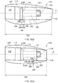
Figure 2(a) is a schematic sectional side view of a gas turbine engine, showing the nacelle cross-section with a conventional accessory gearbox; and -
Figure 2(b) is a schematic sectional side view of a gas turbine engine, showing the nacelle cross-section with an axially-aligned accessory gearbox. -
Figure 2(a) shows agas turbine engine 110 comprising anacelle air intake 112, afan casing 113, anIMC 114, and acore engine 180 mounted within abypass casing 182. (For other engine architectures, an ICC may take the place of theIMC 114.) Thecore engine 180 and thebypass casing 182 together define anannular bypass duct 121. As in the engine shown inFigure 1 , air entering thenacelle air intake 112 is accelerated by a fan (not shown inFigure 2(a) ) to produce two air flows: a first air flow into thecore engine 180 and a second air flow which passes through thebypass duct 121 to provide propulsive thrust. The core engine air flow is exhausted through anozzle 118; the bypass air flow is exhausted through abypass nozzle 119 defined by anacelle 120. - Mounted to the IMC 114 is an
accessory gearbox 140, on which are mounted a number of accessories 190 (only two shown). Theaccessories 190 may be of any known type (for example starter, hydraulic pump, heat exchanger, breather, oil pump, drains tank, hydro-mechanical unit (HMU), fuel pump, alternator). - The nacelle outer contour (i.e. the profile of the outer skin of the
nacelle 120 around and along the whole engine) is constrained by the need to maintain a minimum clearance 196 between the dressed engine and the nacelle outer skin. Because theaccessory gearbox 140 protrudes from the lower part of the IMC and because there is no corresponding protrusion from the upper part of the IMC, the lower part of the nacelle extends further away 198 from thebypass duct casing 182 than does theupper part 199, so that the outer contour of thenacelle 120 is non-circular. The nacelle outer contour along the lower part of the engine therefore constrains the loft lines and thereby theoverall length 160 of the nacelle, which is greater than if it were constrained by the nacelle outer contour along the upper part of the engine. -
Figure 2(b) shows agas turbine engine 210. Like the engine ofFigure 2(a) , thegas turbine engine 210 comprises anacelle air intake 112, afan casing 113, anIMC 114, and acore engine 180 mounted within abypass casing 282. Thecore engine 180 and thebypass casing 282 together define anannular bypass duct 121. As in the engine shown inFigure 1 , air entering thenacelle intake 112 is accelerated by a fan to produce two air flows: a first air flow into thecore engine 180 and a second air flow which passes through thebypass duct 121 to provide propulsive thrust. The core engine air flow is exhausted through anozzle 118; the bypass air flow is exhausted through abypass nozzle 219 defined by anacelle 220. - Mounted to the
bypass casing 282 is an axially-alignedaccessory gearbox 240, on which are mounted a number of accessories 290 (only three shown). Theaccessories 290 may be of any known type, as described above. - In the arrangement of
Figure 2(b) , thebypass casing 282 comprises a recess configured to accommodate theaccessory gearbox 240, so that theaccessory gearbox 240 is partially inset into thebypass casing 282 and protrudes less far in a radial direction than if the recess were not present. - The radially inward contouring of the
bypass casing 282 to accommodate theaccessory gearbox 240 results in a corresponding contouring on the inner wall of thebypass casing 282, which locally reduces the cross-sectional area of thebypass duct 121. This inevitably increases the bypass losses, but because the bypass flow velocity is lower than the flow velocity outside the nacelle, a geometrically identical blockage will cause less loss in the bypass and hence result in an overall reduced loss (at engine / power plant level). - The increased bypass losses can be mitigated by a corresponding radially inward contouring of the
bypass duct 121 inner wall (formed by, for example, the fairings of thecore engine 180 or inner fixed structure(not shown inFigure 2(b) ) so that there is no or less local reduction in thebypass duct 121 cross-sectional area. The benefit of the axially mounted accessory gearbox can thus be maximised. - As in the engine shown in
Figure 2(a) , it is necessary to maintain aminimum clearance 296 between the dressed engine and the nacelle outer skin. The axially-extendingaccessory gearbox 240 protrudes less far from thebypass casing 282 than does theconventional accessory gearbox 140 in the arrangement ofFigure 2(a) . Therefore, the lower part of thenacelle 220 extends less far 298 from thebypass casing 282 than in the arrangement of Figure 3(a). Theupper dimension 299 is the same as thecorresponding dimension 199 in Figure 3(a), so the outer casing line of thenacelle 220 is smaller than the outer casing line of thenacelle 120. - Because the outer casing line of the
nacelle 220 is smaller than the outer casing line of thenacelle 120, theoverall length 260 of thenacelle 220 can be made shorter than theoverall length 160 of thenacelle 120 without introducing aerodynamically unacceptable curvatures. The reduced length and reduced outer casing line of thenacelle 220 deliver a significant reduction in weight compared with theconventional nacelle 120, and the reduced outer casing line also delivers an aerodynamic benefit. - In an alternative arrangement, the
bypass casing 282 may comprise no recess, so that theaccessory gearbox 240 is simply mounted on thebypass casing 282. This will cause theaccessory gearbox 240 to protrude further in a radial direction than in the arrangement ofFigure 2(b) , and therefore the outer casing line will be larger than for the arrangement ofFigure 2(b) . - It will be understood that the invention is not limited to the embodiments described and various modifications and improvements can be made without departing from the concepts described herein. Except where mutually exclusive, any of the features may be employed separately or in combination with any other features and the disclosure extends to and includes all combinations and subcombinations of one or more features described herein.
Claims (6)
- A gas turbine engine arrangement, the engine (210) comprising an accessory gearbox (240), the arrangement characterised in that the accessory gearbox is aligned in an axial direction along the engine.
- The arrangement of claim 1, in which the accessory gearbox is mounted on a casing (282) of the engine, and in which the accessory gearbox is recessed at least partly into the casing.
- The arrangement of claim 2, in which the casing comprises a recess to accommodate the accessory gearbox.
- The arrangement of claim 3, in which the recess causes a reduction in the bypass duct (121) cross-sectional area in the region of the recess.
- The arrangement of claim 4, in which the inner wall of the bypass duct comprises a corresponding recess to mitigate the reduction in cross-sectional area.
- The arrangement of any one of the preceding claims, in which the axial alignment of the accessory gearbox permits a reduction in the outer casing line of the nacelle and therefore a reduction in the overall length of the nacelle.
Applications Claiming Priority (1)
| Application Number | Priority Date | Filing Date | Title |
|---|---|---|---|
| GBGB1616759.5A GB201616759D0 (en) | 2016-10-03 | 2016-10-03 | Accessory gearbox for a gas turbine engine |
Publications (2)
| Publication Number | Publication Date |
|---|---|
| EP3301288A1 true EP3301288A1 (en) | 2018-04-04 |
| EP3301288B1 EP3301288B1 (en) | 2019-10-02 |
Family
ID=57571210
Family Applications (1)
| Application Number | Title | Priority Date | Filing Date |
|---|---|---|---|
| EP17194297.2A Active EP3301288B1 (en) | 2016-10-03 | 2017-10-02 | Accessory gearbox for a gas turbine engine |
Country Status (3)
| Country | Link |
|---|---|
| US (1) | US10968833B2 (en) |
| EP (1) | EP3301288B1 (en) |
| GB (1) | GB201616759D0 (en) |
Citations (5)
| Publication number | Priority date | Publication date | Assignee | Title |
|---|---|---|---|---|
| US20060101804A1 (en) * | 2003-07-08 | 2006-05-18 | Stretton Richard G | Aircraft engine arrangement |
| EP2011979A2 (en) * | 2007-06-28 | 2009-01-07 | United Technologies Corporation | Generator with separate Oil System |
| US20120117981A1 (en) * | 2010-11-17 | 2012-05-17 | Suciu Gabriel L | Axial accessory gearbox |
| US20160040601A1 (en) * | 2011-06-14 | 2016-02-11 | Honeywell International Inc. | Transverse mounted accessory gearbox |
| EP3054128A1 (en) * | 2015-02-09 | 2016-08-10 | United Technologies Corporation | Gearbox for gas turbine engine |
Family Cites Families (5)
| Publication number | Priority date | Publication date | Assignee | Title |
|---|---|---|---|---|
| US7090165B2 (en) * | 2003-06-02 | 2006-08-15 | Rolls-Royce Plc | Aeroengine nacelle |
| US20060137355A1 (en) * | 2004-12-27 | 2006-06-29 | Pratt & Whitney Canada Corp. | Fan driven emergency generator |
| US8602717B2 (en) * | 2010-10-28 | 2013-12-10 | United Technologies Corporation | Compression system for turbomachine heat exchanger |
| DE102011112250A1 (en) * | 2011-09-02 | 2013-03-07 | Rolls-Royce Deutschland Ltd & Co Kg | Auxiliary gear device for an engine |
| US20140090386A1 (en) * | 2012-09-28 | 2014-04-03 | United Technologies Corporation | Geared turbofan with fan and core mounted accessory gearboxes |
-
2016
- 2016-10-03 GB GBGB1616759.5A patent/GB201616759D0/en not_active Ceased
-
2017
- 2017-10-02 EP EP17194297.2A patent/EP3301288B1/en active Active
- 2017-10-02 US US15/722,421 patent/US10968833B2/en active Active
Patent Citations (5)
| Publication number | Priority date | Publication date | Assignee | Title |
|---|---|---|---|---|
| US20060101804A1 (en) * | 2003-07-08 | 2006-05-18 | Stretton Richard G | Aircraft engine arrangement |
| EP2011979A2 (en) * | 2007-06-28 | 2009-01-07 | United Technologies Corporation | Generator with separate Oil System |
| US20120117981A1 (en) * | 2010-11-17 | 2012-05-17 | Suciu Gabriel L | Axial accessory gearbox |
| US20160040601A1 (en) * | 2011-06-14 | 2016-02-11 | Honeywell International Inc. | Transverse mounted accessory gearbox |
| EP3054128A1 (en) * | 2015-02-09 | 2016-08-10 | United Technologies Corporation | Gearbox for gas turbine engine |
Also Published As
| Publication number | Publication date |
|---|---|
| US20180094717A1 (en) | 2018-04-05 |
| EP3301288B1 (en) | 2019-10-02 |
| US10968833B2 (en) | 2021-04-06 |
| GB201616759D0 (en) | 2016-11-16 |
Similar Documents
| Publication | Publication Date | Title |
|---|---|---|
| EP3339607B1 (en) | Reverse flow engine architecture | |
| US10823080B2 (en) | Dual accessory gearbox | |
| US8328504B2 (en) | Aeroengine drain assembly | |
| US8333554B2 (en) | Split gearbox and nacelle arrangement | |
| CN108350755B (en) | Aircraft turbomachine front section | |
| US20160237906A1 (en) | Intercooled cooling air with heat exchanger packaging | |
| US20190218978A1 (en) | Accessory gearbox assembly and a gas turbine engine comprising an accessory gearbox assembly | |
| EP3187712B1 (en) | Nacelle short inlet | |
| US10077715B2 (en) | Accessory gearbox | |
| US20160333786A1 (en) | System for supporting rotor shafts of an indirect drive turbofan engine | |
| US20140090388A1 (en) | Off-take power ratio | |
| US11143110B2 (en) | Aeroderivative jet engine accessory starter relocation to main shaft—directly connected to HPC shaft | |
| US10385785B2 (en) | Air inlet for a gas turbine engine | |
| EP2917508B1 (en) | Gas turbine engine with a compressor bleed air slot | |
| US20180216631A1 (en) | Geared gas turbine engine | |
| CN113090347B (en) | Air starter with bearing cooling | |
| EP3536902B1 (en) | Gas turbine engine component | |
| EP3109435B1 (en) | Intercooled cooling air with heat exchanger packaging | |
| US10968833B2 (en) | Accessory gearbox for a gas turbine engine | |
| EP3351752A1 (en) | Gas turbine engine arrangement | |
| CN116209821A (en) | Turbine module provided with a propeller and offset stator vanes | |
| US20240263586A1 (en) | Turbine engine including transfer gearbox and accessory gearbox | |
| CA2992784A1 (en) | Gas turbine engine arrangement |
Legal Events
| Date | Code | Title | Description |
|---|---|---|---|
| PUAI | Public reference made under article 153(3) epc to a published international application that has entered the european phase |
Free format text: ORIGINAL CODE: 0009012 |
|
| STAA | Information on the status of an ep patent application or granted ep patent |
Free format text: STATUS: THE APPLICATION HAS BEEN PUBLISHED |
|
| AK | Designated contracting states |
Kind code of ref document: A1 Designated state(s): AL AT BE BG CH CY CZ DE DK EE ES FI FR GB GR HR HU IE IS IT LI LT LU LV MC MK MT NL NO PL PT RO RS SE SI SK SM TR |
|
| AX | Request for extension of the european patent |
Extension state: BA ME |
|
| STAA | Information on the status of an ep patent application or granted ep patent |
Free format text: STATUS: REQUEST FOR EXAMINATION WAS MADE |
|
| 17P | Request for examination filed |
Effective date: 20181130 |
|
| RBV | Designated contracting states (corrected) |
Designated state(s): AL AT BE BG CH CY CZ DE DK EE ES FI FR GB GR HR HU IE IS IT LI LT LU LV MC MK MT NL NO PL PT RO RS SE SI SK SM TR |
|
| GRAP | Despatch of communication of intention to grant a patent |
Free format text: ORIGINAL CODE: EPIDOSNIGR1 |
|
| STAA | Information on the status of an ep patent application or granted ep patent |
Free format text: STATUS: GRANT OF PATENT IS INTENDED |
|
| INTG | Intention to grant announced |
Effective date: 20190719 |
|
| GRAS | Grant fee paid |
Free format text: ORIGINAL CODE: EPIDOSNIGR3 |
|
| GRAA | (expected) grant |
Free format text: ORIGINAL CODE: 0009210 |
|
| STAA | Information on the status of an ep patent application or granted ep patent |
Free format text: STATUS: THE PATENT HAS BEEN GRANTED |
|
| AK | Designated contracting states |
Kind code of ref document: B1 Designated state(s): AL AT BE BG CH CY CZ DE DK EE ES FI FR GB GR HR HU IE IS IT LI LT LU LV MC MK MT NL NO PL PT RO RS SE SI SK SM TR |
|
| REG | Reference to a national code |
Ref country code: GB Ref legal event code: FG4D |
|
| REG | Reference to a national code |
Ref country code: CH Ref legal event code: EP Ref country code: AT Ref legal event code: REF Ref document number: 1186439 Country of ref document: AT Kind code of ref document: T Effective date: 20191015 |
|
| REG | Reference to a national code |
Ref country code: DE Ref legal event code: R096 Ref document number: 602017007444 Country of ref document: DE |
|
| REG | Reference to a national code |
Ref country code: IE Ref legal event code: FG4D |
|
| REG | Reference to a national code |
Ref country code: NL Ref legal event code: MP Effective date: 20191002 |
|
| REG | Reference to a national code |
Ref country code: LT Ref legal event code: MG4D |
|
| REG | Reference to a national code |
Ref country code: AT Ref legal event code: MK05 Ref document number: 1186439 Country of ref document: AT Kind code of ref document: T Effective date: 20191002 |
|
| PG25 | Lapsed in a contracting state [announced via postgrant information from national office to epo] |
Ref country code: ES Free format text: LAPSE BECAUSE OF FAILURE TO SUBMIT A TRANSLATION OF THE DESCRIPTION OR TO PAY THE FEE WITHIN THE PRESCRIBED TIME-LIMIT Effective date: 20191002 Ref country code: PT Free format text: LAPSE BECAUSE OF FAILURE TO SUBMIT A TRANSLATION OF THE DESCRIPTION OR TO PAY THE FEE WITHIN THE PRESCRIBED TIME-LIMIT Effective date: 20200203 Ref country code: FI Free format text: LAPSE BECAUSE OF FAILURE TO SUBMIT A TRANSLATION OF THE DESCRIPTION OR TO PAY THE FEE WITHIN THE PRESCRIBED TIME-LIMIT Effective date: 20191002 Ref country code: NO Free format text: LAPSE BECAUSE OF FAILURE TO SUBMIT A TRANSLATION OF THE DESCRIPTION OR TO PAY THE FEE WITHIN THE PRESCRIBED TIME-LIMIT Effective date: 20200102 Ref country code: SE Free format text: LAPSE BECAUSE OF FAILURE TO SUBMIT A TRANSLATION OF THE DESCRIPTION OR TO PAY THE FEE WITHIN THE PRESCRIBED TIME-LIMIT Effective date: 20191002 Ref country code: LV Free format text: LAPSE BECAUSE OF FAILURE TO SUBMIT A TRANSLATION OF THE DESCRIPTION OR TO PAY THE FEE WITHIN THE PRESCRIBED TIME-LIMIT Effective date: 20191002 Ref country code: PL Free format text: LAPSE BECAUSE OF FAILURE TO SUBMIT A TRANSLATION OF THE DESCRIPTION OR TO PAY THE FEE WITHIN THE PRESCRIBED TIME-LIMIT Effective date: 20191002 Ref country code: LT Free format text: LAPSE BECAUSE OF FAILURE TO SUBMIT A TRANSLATION OF THE DESCRIPTION OR TO PAY THE FEE WITHIN THE PRESCRIBED TIME-LIMIT Effective date: 20191002 Ref country code: NL Free format text: LAPSE BECAUSE OF FAILURE TO SUBMIT A TRANSLATION OF THE DESCRIPTION OR TO PAY THE FEE WITHIN THE PRESCRIBED TIME-LIMIT Effective date: 20191002 Ref country code: GR Free format text: LAPSE BECAUSE OF FAILURE TO SUBMIT A TRANSLATION OF THE DESCRIPTION OR TO PAY THE FEE WITHIN THE PRESCRIBED TIME-LIMIT Effective date: 20200103 Ref country code: BG Free format text: LAPSE BECAUSE OF FAILURE TO SUBMIT A TRANSLATION OF THE DESCRIPTION OR TO PAY THE FEE WITHIN THE PRESCRIBED TIME-LIMIT Effective date: 20200102 Ref country code: AT Free format text: LAPSE BECAUSE OF FAILURE TO SUBMIT A TRANSLATION OF THE DESCRIPTION OR TO PAY THE FEE WITHIN THE PRESCRIBED TIME-LIMIT Effective date: 20191002 |
|
| PG25 | Lapsed in a contracting state [announced via postgrant information from national office to epo] |
Ref country code: CZ Free format text: LAPSE BECAUSE OF FAILURE TO SUBMIT A TRANSLATION OF THE DESCRIPTION OR TO PAY THE FEE WITHIN THE PRESCRIBED TIME-LIMIT Effective date: 20191002 Ref country code: IS Free format text: LAPSE BECAUSE OF FAILURE TO SUBMIT A TRANSLATION OF THE DESCRIPTION OR TO PAY THE FEE WITHIN THE PRESCRIBED TIME-LIMIT Effective date: 20200224 Ref country code: HR Free format text: LAPSE BECAUSE OF FAILURE TO SUBMIT A TRANSLATION OF THE DESCRIPTION OR TO PAY THE FEE WITHIN THE PRESCRIBED TIME-LIMIT Effective date: 20191002 Ref country code: RS Free format text: LAPSE BECAUSE OF FAILURE TO SUBMIT A TRANSLATION OF THE DESCRIPTION OR TO PAY THE FEE WITHIN THE PRESCRIBED TIME-LIMIT Effective date: 20191002 |
|
| PG25 | Lapsed in a contracting state [announced via postgrant information from national office to epo] |
Ref country code: AL Free format text: LAPSE BECAUSE OF FAILURE TO SUBMIT A TRANSLATION OF THE DESCRIPTION OR TO PAY THE FEE WITHIN THE PRESCRIBED TIME-LIMIT Effective date: 20191002 |
|
| REG | Reference to a national code |
Ref country code: DE Ref legal event code: R097 Ref document number: 602017007444 Country of ref document: DE |
|
| PG2D | Information on lapse in contracting state deleted |
Ref country code: IS |
|
| PG25 | Lapsed in a contracting state [announced via postgrant information from national office to epo] |
Ref country code: RO Free format text: LAPSE BECAUSE OF FAILURE TO SUBMIT A TRANSLATION OF THE DESCRIPTION OR TO PAY THE FEE WITHIN THE PRESCRIBED TIME-LIMIT Effective date: 20191002 Ref country code: DK Free format text: LAPSE BECAUSE OF FAILURE TO SUBMIT A TRANSLATION OF THE DESCRIPTION OR TO PAY THE FEE WITHIN THE PRESCRIBED TIME-LIMIT Effective date: 20191002 Ref country code: EE Free format text: LAPSE BECAUSE OF FAILURE TO SUBMIT A TRANSLATION OF THE DESCRIPTION OR TO PAY THE FEE WITHIN THE PRESCRIBED TIME-LIMIT Effective date: 20191002 Ref country code: MC Free format text: LAPSE BECAUSE OF FAILURE TO SUBMIT A TRANSLATION OF THE DESCRIPTION OR TO PAY THE FEE WITHIN THE PRESCRIBED TIME-LIMIT Effective date: 20191002 Ref country code: LU Free format text: LAPSE BECAUSE OF NON-PAYMENT OF DUE FEES Effective date: 20191002 Ref country code: IS Free format text: LAPSE BECAUSE OF FAILURE TO SUBMIT A TRANSLATION OF THE DESCRIPTION OR TO PAY THE FEE WITHIN THE PRESCRIBED TIME-LIMIT Effective date: 20200202 |
|
| PLBE | No opposition filed within time limit |
Free format text: ORIGINAL CODE: 0009261 |
|
| STAA | Information on the status of an ep patent application or granted ep patent |
Free format text: STATUS: NO OPPOSITION FILED WITHIN TIME LIMIT |
|
| REG | Reference to a national code |
Ref country code: BE Ref legal event code: MM Effective date: 20191031 |
|
| PG25 | Lapsed in a contracting state [announced via postgrant information from national office to epo] |
Ref country code: BE Free format text: LAPSE BECAUSE OF NON-PAYMENT OF DUE FEES Effective date: 20191031 Ref country code: IT Free format text: LAPSE BECAUSE OF FAILURE TO SUBMIT A TRANSLATION OF THE DESCRIPTION OR TO PAY THE FEE WITHIN THE PRESCRIBED TIME-LIMIT Effective date: 20191002 Ref country code: SM Free format text: LAPSE BECAUSE OF FAILURE TO SUBMIT A TRANSLATION OF THE DESCRIPTION OR TO PAY THE FEE WITHIN THE PRESCRIBED TIME-LIMIT Effective date: 20191002 Ref country code: SK Free format text: LAPSE BECAUSE OF FAILURE TO SUBMIT A TRANSLATION OF THE DESCRIPTION OR TO PAY THE FEE WITHIN THE PRESCRIBED TIME-LIMIT Effective date: 20191002 |
|
| 26N | No opposition filed |
Effective date: 20200703 |
|
| PG25 | Lapsed in a contracting state [announced via postgrant information from national office to epo] |
Ref country code: IE Free format text: LAPSE BECAUSE OF NON-PAYMENT OF DUE FEES Effective date: 20191002 |
|
| PG25 | Lapsed in a contracting state [announced via postgrant information from national office to epo] |
Ref country code: SI Free format text: LAPSE BECAUSE OF FAILURE TO SUBMIT A TRANSLATION OF THE DESCRIPTION OR TO PAY THE FEE WITHIN THE PRESCRIBED TIME-LIMIT Effective date: 20191002 |
|
| PG25 | Lapsed in a contracting state [announced via postgrant information from national office to epo] |
Ref country code: CY Free format text: LAPSE BECAUSE OF FAILURE TO SUBMIT A TRANSLATION OF THE DESCRIPTION OR TO PAY THE FEE WITHIN THE PRESCRIBED TIME-LIMIT Effective date: 20191002 |
|
| REG | Reference to a national code |
Ref country code: CH Ref legal event code: PL |
|
| PG25 | Lapsed in a contracting state [announced via postgrant information from national office to epo] |
Ref country code: HU Free format text: LAPSE BECAUSE OF FAILURE TO SUBMIT A TRANSLATION OF THE DESCRIPTION OR TO PAY THE FEE WITHIN THE PRESCRIBED TIME-LIMIT; INVALID AB INITIO Effective date: 20171002 Ref country code: MT Free format text: LAPSE BECAUSE OF FAILURE TO SUBMIT A TRANSLATION OF THE DESCRIPTION OR TO PAY THE FEE WITHIN THE PRESCRIBED TIME-LIMIT Effective date: 20191002 |
|
| PG25 | Lapsed in a contracting state [announced via postgrant information from national office to epo] |
Ref country code: CH Free format text: LAPSE BECAUSE OF NON-PAYMENT OF DUE FEES Effective date: 20201031 Ref country code: LI Free format text: LAPSE BECAUSE OF NON-PAYMENT OF DUE FEES Effective date: 20201031 |
|
| PG25 | Lapsed in a contracting state [announced via postgrant information from national office to epo] |
Ref country code: TR Free format text: LAPSE BECAUSE OF FAILURE TO SUBMIT A TRANSLATION OF THE DESCRIPTION OR TO PAY THE FEE WITHIN THE PRESCRIBED TIME-LIMIT Effective date: 20191002 |
|
| PG25 | Lapsed in a contracting state [announced via postgrant information from national office to epo] |
Ref country code: MK Free format text: LAPSE BECAUSE OF FAILURE TO SUBMIT A TRANSLATION OF THE DESCRIPTION OR TO PAY THE FEE WITHIN THE PRESCRIBED TIME-LIMIT Effective date: 20191002 |
|
| P01 | Opt-out of the competence of the unified patent court (upc) registered |
Effective date: 20230528 |
|
| PGFP | Annual fee paid to national office [announced via postgrant information from national office to epo] |
Ref country code: GB Payment date: 20231024 Year of fee payment: 7 |
|
| PGFP | Annual fee paid to national office [announced via postgrant information from national office to epo] |
Ref country code: FR Payment date: 20231026 Year of fee payment: 7 Ref country code: DE Payment date: 20231027 Year of fee payment: 7 |