EP3301265B1 - Graphenwärmerohr für ein gasturbinentriebwerk, zugehöriges gasturbinentriebwerk sowie verfahren zur kühlung eines kompressor-strömungskanals in einem gasturbinentriebwerk - Google Patents
Graphenwärmerohr für ein gasturbinentriebwerk, zugehöriges gasturbinentriebwerk sowie verfahren zur kühlung eines kompressor-strömungskanals in einem gasturbinentriebwerk Download PDFInfo
- Publication number
- EP3301265B1 EP3301265B1 EP17193812.9A EP17193812A EP3301265B1 EP 3301265 B1 EP3301265 B1 EP 3301265B1 EP 17193812 A EP17193812 A EP 17193812A EP 3301265 B1 EP3301265 B1 EP 3301265B1
- Authority
- EP
- European Patent Office
- Prior art keywords
- gas turbine
- turbine engine
- graphene
- heat pipe
- flow path
- Prior art date
- Legal status (The legal status is an assumption and is not a legal conclusion. Google has not performed a legal analysis and makes no representation as to the accuracy of the status listed.)
- Active
Links
Images


Classifications
-
- F—MECHANICAL ENGINEERING; LIGHTING; HEATING; WEAPONS; BLASTING
- F01—MACHINES OR ENGINES IN GENERAL; ENGINE PLANTS IN GENERAL; STEAM ENGINES
- F01D—NON-POSITIVE DISPLACEMENT MACHINES OR ENGINES, e.g. STEAM TURBINES
- F01D25/00—Component parts, details, or accessories, not provided for in, or of interest apart from, other groups
- F01D25/08—Cooling; Heating; Heat-insulation
- F01D25/12—Cooling
-
- F—MECHANICAL ENGINEERING; LIGHTING; HEATING; WEAPONS; BLASTING
- F01—MACHINES OR ENGINES IN GENERAL; ENGINE PLANTS IN GENERAL; STEAM ENGINES
- F01D—NON-POSITIVE DISPLACEMENT MACHINES OR ENGINES, e.g. STEAM TURBINES
- F01D5/00—Blades; Blade-carrying members; Heating, heat-insulating, cooling or antivibration means on the blades or the members
- F01D5/02—Blade-carrying members, e.g. rotors
- F01D5/08—Heating, heat-insulating or cooling means
-
- F—MECHANICAL ENGINEERING; LIGHTING; HEATING; WEAPONS; BLASTING
- F28—HEAT EXCHANGE IN GENERAL
- F28D—HEAT-EXCHANGE APPARATUS, NOT PROVIDED FOR IN ANOTHER SUBCLASS, IN WHICH THE HEAT-EXCHANGE MEDIA DO NOT COME INTO DIRECT CONTACT
- F28D15/00—Heat-exchange apparatus with the intermediate heat-transfer medium in closed tubes passing into or through the conduit walls ; Heat-exchange apparatus employing intermediate heat-transfer medium or bodies
- F28D15/02—Heat-exchange apparatus with the intermediate heat-transfer medium in closed tubes passing into or through the conduit walls ; Heat-exchange apparatus employing intermediate heat-transfer medium or bodies in which the medium condenses and evaporates, e.g. heat pipes
-
- F—MECHANICAL ENGINEERING; LIGHTING; HEATING; WEAPONS; BLASTING
- F28—HEAT EXCHANGE IN GENERAL
- F28D—HEAT-EXCHANGE APPARATUS, NOT PROVIDED FOR IN ANOTHER SUBCLASS, IN WHICH THE HEAT-EXCHANGE MEDIA DO NOT COME INTO DIRECT CONTACT
- F28D15/00—Heat-exchange apparatus with the intermediate heat-transfer medium in closed tubes passing into or through the conduit walls ; Heat-exchange apparatus employing intermediate heat-transfer medium or bodies
- F28D15/02—Heat-exchange apparatus with the intermediate heat-transfer medium in closed tubes passing into or through the conduit walls ; Heat-exchange apparatus employing intermediate heat-transfer medium or bodies in which the medium condenses and evaporates, e.g. heat pipes
- F28D15/04—Heat-exchange apparatus with the intermediate heat-transfer medium in closed tubes passing into or through the conduit walls ; Heat-exchange apparatus employing intermediate heat-transfer medium or bodies in which the medium condenses and evaporates, e.g. heat pipes with tubes having a capillary structure
- F28D15/046—Heat-exchange apparatus with the intermediate heat-transfer medium in closed tubes passing into or through the conduit walls ; Heat-exchange apparatus employing intermediate heat-transfer medium or bodies in which the medium condenses and evaporates, e.g. heat pipes with tubes having a capillary structure characterised by the material or the construction of the capillary structure
-
- F—MECHANICAL ENGINEERING; LIGHTING; HEATING; WEAPONS; BLASTING
- F28—HEAT EXCHANGE IN GENERAL
- F28F—DETAILS OF HEAT-EXCHANGE AND HEAT-TRANSFER APPARATUS, OF GENERAL APPLICATION
- F28F21/00—Constructions of heat-exchange apparatus characterised by the selection of particular materials
- F28F21/02—Constructions of heat-exchange apparatus characterised by the selection of particular materials of carbon, e.g. graphite
-
- F—MECHANICAL ENGINEERING; LIGHTING; HEATING; WEAPONS; BLASTING
- F02—COMBUSTION ENGINES; HOT-GAS OR COMBUSTION-PRODUCT ENGINE PLANTS
- F02C—GAS-TURBINE PLANTS; AIR INTAKES FOR JET-PROPULSION PLANTS; CONTROLLING FUEL SUPPLY IN AIR-BREATHING JET-PROPULSION PLANTS
- F02C7/00—Features, components parts, details or accessories, not provided for in, or of interest apart form groups F02C1/00 - F02C6/00; Air intakes for jet-propulsion plants
- F02C7/08—Heating air supply before combustion, e.g. by exhaust gases
-
- F—MECHANICAL ENGINEERING; LIGHTING; HEATING; WEAPONS; BLASTING
- F05—INDEXING SCHEMES RELATING TO ENGINES OR PUMPS IN VARIOUS SUBCLASSES OF CLASSES F01-F04
- F05D—INDEXING SCHEME FOR ASPECTS RELATING TO NON-POSITIVE-DISPLACEMENT MACHINES OR ENGINES, GAS-TURBINES OR JET-PROPULSION PLANTS
- F05D2220/00—Application
- F05D2220/30—Application in turbines
- F05D2220/36—Application in turbines specially adapted for the fan of turbofan engines
-
- F—MECHANICAL ENGINEERING; LIGHTING; HEATING; WEAPONS; BLASTING
- F05—INDEXING SCHEMES RELATING TO ENGINES OR PUMPS IN VARIOUS SUBCLASSES OF CLASSES F01-F04
- F05D—INDEXING SCHEME FOR ASPECTS RELATING TO NON-POSITIVE-DISPLACEMENT MACHINES OR ENGINES, GAS-TURBINES OR JET-PROPULSION PLANTS
- F05D2260/00—Function
- F05D2260/20—Heat transfer, e.g. cooling
- F05D2260/208—Heat transfer, e.g. cooling using heat pipes
-
- F—MECHANICAL ENGINEERING; LIGHTING; HEATING; WEAPONS; BLASTING
- F28—HEAT EXCHANGE IN GENERAL
- F28D—HEAT-EXCHANGE APPARATUS, NOT PROVIDED FOR IN ANOTHER SUBCLASS, IN WHICH THE HEAT-EXCHANGE MEDIA DO NOT COME INTO DIRECT CONTACT
- F28D21/00—Heat-exchange apparatus not covered by any of the groups F28D1/00 - F28D20/00
- F28D2021/0019—Other heat exchangers for particular applications; Heat exchange systems not otherwise provided for
- F28D2021/0026—Other heat exchangers for particular applications; Heat exchange systems not otherwise provided for for combustion engines, e.g. for gas turbines or for Stirling engines
-
- Y—GENERAL TAGGING OF NEW TECHNOLOGICAL DEVELOPMENTS; GENERAL TAGGING OF CROSS-SECTIONAL TECHNOLOGIES SPANNING OVER SEVERAL SECTIONS OF THE IPC; TECHNICAL SUBJECTS COVERED BY FORMER USPC CROSS-REFERENCE ART COLLECTIONS [XRACs] AND DIGESTS
- Y02—TECHNOLOGIES OR APPLICATIONS FOR MITIGATION OR ADAPTATION AGAINST CLIMATE CHANGE
- Y02T—CLIMATE CHANGE MITIGATION TECHNOLOGIES RELATED TO TRANSPORTATION
- Y02T50/00—Aeronautics or air transport
- Y02T50/60—Efficient propulsion technologies, e.g. for aircraft
Definitions
- This disclosure relates to graphene heat pipes for cooling a compressor flow path of a gas turbine engine, corresponding methods and gas turbine engines for aircrafts.
- cooling systems can be used to reduce temperatures at the back end of the high compressor adds to overall system weight and cost. Cooling systems that use materials with lower thermal conductivity can require a substantial amount of surface area to remove heat from the compressor flow path.
- WO 2014/200597 A2 discloses a heat transfer device serving as a heat sink in a gas turbine engine.
- GB 1516041 A discloses heat pipes for transferring heat from a flow of compressed air in a gas turbine engine in accordance with the preamble of claim 1.
- FR 2915920 A1 discloses a heat pipe mounted on a rectifier stage of a turbo machine.
- the invention provides a graphene heat pipe for cooling a compressor flow path of a gas turbine engine including a body of graphene.
- the body has a hot side to accept heat from the gas turbine engine, a cold side to reject heat from the body, and an adiabatic portion to flow heat within the body between the hot side and the cold side.
- the body is comprised of a wound coil, and the body is formed into a solid structure absent an interior phase change volume.
- further embodiments may include where the body is at least partially coated with graphene.
- further embodiments may include where the body is integrally formed of graphene.
- further embodiments may include at least one end cap to establish a closed fluid flow environment within the graphene heat pipe.
- further embodiments may include a wick structure within the body, where the wick structure divides a vapor flow channel from a liquid flow channel within the body.
- wick structure is one of a sintered wick, a mesh wick, a grooved wick or a combination thereof
- a working fluid of the graphene heat pipe is one of glycol, water, alcohol, refrigerant, or a mixture thereof.
- the invention provides a gas turbine engine of an aircraft comprising a graphene heat pipe as described in any of the preceding statements.
- the gas turbine engine includes a fan section comprising a fan duct that establishes a fan flow path, a compressor section including a plurality of blades and vanes that establish a compressor flow path, and a graphene heat pipe.
- the graphene heat pipe is installed to flow heat from the compressor flow path to the fan flow path.
- graphene heat pipe includes a body of graphene having a hot side to accept heat from the compressor flow path, a cold side to reject heat from the body to the fan flow path, and an adiabatic portion to flow heat within the body between the hot side and the cold side.
- further embodiments may include where the hot side of the body is installed within one of the vanes of the compressor section of the gas turbine engine.
- the invention provides a method for cooling a compressor flow path of a gas turbine engine including providing a graphene heat pipe within the gas turbine engine and accepting heat at a hot side of the graphene heat pipe proximate to a compressor flow path of the gas turbine engine.
- the method further includes flowing heat from the hot side of the graphene heat pipe through an adiabatic portion of the graphene heat pipe to a cold side of the graphene heat pipe and rejecting heat from the cold side of the graphene heat pipe to a fan flow path of the gas turbine engine.
- the graphene heat pipe is a wound coil of graphene or a coiled substrate coated with graphene formed into a solid structure absent an interior phase change volume.
- further embodiments may include where providing the graphene heat pipe further includes installing the graphene heat pipe within one of a plurality of vanes of a compressor section of the gas turbine engine.
- further embodiments may include installing a plurality of the graphene heat pipes at a plurality of axially and/or radially distributed locations within the gas turbine engine.
- a technical effect of the apparatus, systems and methods is achieved by using one or more graphene heat pipes in a gas turbine engine as described herein.
- Various embodiments of the present disclosure are related to heat reduction within a gas turbine engine using one or more graphene heat pipes.
- One or more graphene heat pipes can be used to transfer heat from an engine core flow (also referred to as a compressor flow path) to a fan stream (also referred to as a fan flow path).
- an engine core flow also referred to as a compressor flow path
- a fan stream also referred to as a fan flow path.
- a graphene heat pipe can have about ten times the thermal conductivity of a plain copper heat pipe.
- the graphene heat pipe is formed as a graphene coating applied to a substrate, such as a copper substrate at least partially coated in graphene.
- graphene can be infused within a substrate to improve structural properties of the graphene while substantially retaining the thermal conductivity properties of graphene.
- a body of the heat pipe is entirely formed of graphene.
- FIG. 1 schematically illustrates a gas turbine engine 10 that can be used to power an aircraft, for example.
- the gas turbine engine 10 is disclosed herein as a multi-spool turbofan that generally incorporates a fan section 22, a compressor section 24, a combustor section 26 and a turbine section 28.
- the fan section 22 drives air along a fan flow path B (also referred to as bypass flow path B) established by fan duct 92, while the compressor section 24 drives air along a compressor flow path C (also referred to as core flow path C) for compression and communication into the combustor section 26 then expansion through the turbine section 28.
- a fan flow path B also referred to as bypass flow path B
- compressor section 24 drives air along a compressor flow path C (also referred to as core flow path C) for compression and communication into the combustor section 26 then expansion through the turbine section 28.
- core flow path C also referred to as core flow path C
- a three-spool architecture can include three spools that concentrically rotate about a common axis and where a low spool enables a low pressure turbine to drive a fan via a gearbox, an intermediate spool that enables an intermediate pressure turbine to drive a first compressor of the compressor section, and a high spool that enables a high pressure turbine to drive a high pressure compressor of the compressor section.
- the engine 10 generally includes a low speed spool 30 and a high speed spool 32 mounted for rotation about an engine central longitudinal axis A relative to an engine static structure 36 via several bearing systems 38. It should be understood that various bearing systems 38 at various locations may alternatively or additionally be provided.
- the low speed spool 30 generally includes an inner shaft 40 that interconnects a fan 42, a low pressure compressor 44 and a low pressure turbine 46.
- the inner shaft 40 is connected to the fan 42 through a geared architecture 48 to drive the fan 42 at a lower speed than the low speed spool 30 in the example of FIG. 1 .
- the high speed spool 32 includes an outer shaft 50 that interconnects a high pressure compressor 52 and high pressure turbine 54.
- the geared architecture 48 is omitted.
- a combustor 56 is arranged between the high pressure compressor 52 and the high pressure turbine 54.
- a mid-turbine frame 57 of the engine static structure 36 is arranged generally between the high pressure turbine 54 and the low pressure turbine 46.
- the mid-turbine frame 57 further supports bearing systems 38 in the turbine section 28.
- the inner shaft 40 and the outer shaft 50 are concentric and rotate via bearing systems 38 about the engine central longitudinal axis A, which is collinear with their longitudinal axes.
- the core airflow is compressed by the low pressure compressor 44 then the high pressure compressor 52, mixed and burned with fuel in the combustor 56, then expanded over the high pressure turbine 54 and low pressure turbine 46.
- the mid-turbine frame 57 includes airfoils 59 which are in the core airflow path.
- the turbines 46, 54 rotationally drive the respective low speed spool 30 and high speed spool 32 in response to the expansion.
- Station 2 is at an inlet of low pressure compressor 44 having a temperature T2 and a pressure P2.
- Station 2.5 is at an exit of the low pressure compressor 44 having a temperature T2.5 and a pressure P2.5.
- Station 3 is at an inlet of the combustor 56 having a temperature T3 and a pressure P3.
- Station 4 is at an exit of the combustor 56 having a temperature T4 and a pressure P4.
- Station 4.5 is at an exit of the high pressure turbine 54 having a temperature T4.5 and a pressure P4.5.
- Station 5 is at an exit of the low pressure turbine 46 having a temperature T5 and a pressure P5.
- Embodiments add one or more graphene heat pipes axially upstream of station 3 to reduce temperature T3 under nominal operating conditions.
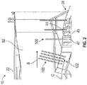
- FIG. 2 is a partial view of graphene heat pipe installation location examples in the gas turbine engine 10 of FIG. 1 .
- the compressor section 24 includes a plurality of blades 45 and vanes 47 that establish the compressor flow path C.
- one or more graphene heat pipes 100 can be axially distributed at compressor inlet 102 and/or throughout the compressor section 24, particularly in the low pressure compressor 44.
- the graphene heat pipes 100 can also be radially distributed, for instance, with multiple graphene heat pipes 100 distributed proximate to or within vanes 47 of a same compressor stage.
- each of the graphene heat pipes 100 located within one of the vanes 47 may have a diameter of about 0.25 inches.
- Each of the graphene heat pipes 100 can be installed between the compressor section 24 and the fan section 22 to flow heat from the compressor flow path C to the fan flow path B.
- FIG. 3 depicts an example of a graphene heat pipe 100A as an embodiment of the graphene heat pipe 100 of FIG. 2 .
- the graphene heat pipe 100A includes a body 104A of graphene, where the body 104A is at least partially coated with graphene, or the body 104A is integrally formed of graphene.
- the body 104A can be a copper substrate that is spray coated or infused with graphene.
- the body 104A includes a hot side 106A that accepts heat from the gas turbine engine 10 of FIG. 1 .
- the body 104A also includes a cold side 108A to reject heat from the body 104A.
- the body 104A further includes an adiabatic portion 110A to flow heat within the body 104A between the hot side 106A and the cold side 108A.
- the graphene heat pipe 100A can also include at least one end cap 112A to establish a closed fluid flow environment within an interior phase change volume of the graphene heat pipe 100A.
- a two-phase working fluid 115A can be circulated within a tubular structure of the body 104A of the graphene heat pipe 100A during normal operation.
- the working fluid 115A can be, for example, one of glycol, water, alcohol, refrigerant, or a mixture thereof.
- a wick structure 114A can divide a vapor flow channel 122A from a liquid flow channel 118A within an interior phase change volume of the body 104A.
- the wick structure 114A within the body 104A can establish a liquid flow 116A of the working fluid 115A in the liquid flow channel 118A and a vapor flow 120A in the vapor flow channel 122A.
- the wick structure 114 can be one of a sintered wick, a mesh wick, a grooved wick or a combination thereof.
- the working fluid 115A is heated in the hot side 106A, changes phase from a liquid to a vapor, and rise as vapor flow 120A in the vapor flow channel 122A toward the cold side 108A.
- the vapor flow 120A cools in the cold side 108A and returns as liquid flow 116A in the liquid flow channel 118A.
- the phase change and flow process repeats within the graphene heat pipe 100A as heat is transferred from the compressor flow path C to the fan flow path B of FIG. 2 .
- FIG. 4 depicts another example of a graphene heat pipe 100B as an embodiment of the graphene heat pipe 100 of FIG. 2 .
- the graphene heat pipe 100B includes a body 104B of graphene, where the body 104B is at least partially coated with graphene, or the body 104B is integrally formed of graphene.
- the body 104B can be a copper substrate that is spray coated or infused with graphene.
- the body 104B includes a hot side 106B that accepts heat from the gas turbine engine 10 of FIG. 1 .
- the body 104B also includes a cold side 108B to reject heat from the body 104B.
- the body 104B further includes an adiabatic portion 110B to flow heat within the body 104B between the hot side 106B and the cold side 108B.
- the graphene heat pipe 100B can also include at least one end cap 112B to establish a closed fluid flow environment within an interior phase change volume of the graphene heat pipe 100B.
- one or more ends of the body 104B directly contacts another surface, such as an interior surface of one of the vanes 47 of FIG. 2 , and end cap 112B can be omitted.
- a working fluid is a gas, such as air, there may not be a wick structure incorporated within the body 104B.
- a hotter flow 120B can transfer heat from the hot side 106B to the cold side 108B, and a cooler flow 116B can return from the cold side 108B to the hot side 106B.
- FIG. 5 depicts a further example of a graphene heat pipe 100C as an embodiment of the graphene heat pipe 100 of FIG. 2 .
- a strip 200 is tightly wrapped into a wound coil 202 to form a body 104C.
- the strip 200 can be at least partially coated with graphene or infused with graphene prior to winding or after winding into the body 104C.
- the body 104C includes an adiabatic portion 110C to flow heat within the body 104C between a hot side 106C and a cold side 108C.
- the graphene heat pipe 100C can also include at least one end cap 112C to establish a closed fluid flow environment within the graphene heat pipe 100C.
- one or more ends of the body 104C directly contacts another surface, such as an interior surface of one of the vanes 47 of FIG. 2 , and end cap 112C can be omitted.
- a working fluid is a gas, such as air, there may not be a wick structure incorporated within the body 104C.
- the body 104C is tightly wound into a substantially solid structure such that the body 104C is formed absent an interior phase change volume and no phase change occurs within the body 104C.
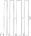
- FIG. 6 is a flow chart illustrating a method 300 for cooling a compressor flow path C of the gas turbine engine 10 in accordance with an embodiment.
- the method 300 of FIG. 6 is described in reference to FIGS. 1-5 and may be performed with an alternate order and include additional steps.
- a graphene heat pipe 100 is provided within the gas turbine engine 10.
- the graphene heat pipe 100 can be embodied as graphene heat pipe 100A, 100B, 100C, or in an alternate arrangement as understood by one of ordinary skill in the art.
- the graphene heat pipe 100A, 100B, 100C may be installed within one of a plurality of vanes 47 of a compressor section 24 of the gas turbine engine 10.
- a plurality of the graphene heat pipes 100A, 100B, 100C can be installed at a plurality of axially and/or radially distributed locations within the gas turbine engine 10, such as within a same stage or multiple stages of the compressor section 24.
- heat is accepted at a hot side 106A, 106B, 106C of the graphene heat pipe 100A, 100B, 100C proximate to compressor flow path C of the gas turbine engine 10.
- heat flows from the hot side 106A, 106B, 106C of the graphene heat pipe 100A, 100B, 100C through an adiabatic portion 110A, 110B, 110C of the graphene heat pipe 100A, 100B, 100C to a cold side 108A, 108B, 108C of the graphene heat pipe 100A, 100B, 100C.
- heat is rejected from cold side 108A, 108B, 108C of the graphene heat pipe 100A, 100B, 100C to fan flow path B of the gas turbine engine 10.
Landscapes
- Engineering & Computer Science (AREA)
- Mechanical Engineering (AREA)
- General Engineering & Computer Science (AREA)
- Physics & Mathematics (AREA)
- Thermal Sciences (AREA)
- Life Sciences & Earth Sciences (AREA)
- Sustainable Development (AREA)
- Structures Of Non-Positive Displacement Pumps (AREA)
Claims (8)
- Graphenwärmerohr zum Kühlen eines Kompressor-Strömungskanals (C) eines Gasturbinentriebwerks (10), wobei das Graphenwärmerohr (100; 100A; 100B; 100C) Folgendes umfasst:einen Körper (104A; 104B; 104C), der eine Warmseite (106A; 106B; 106C) zum Aufnehmen von Wärme aus dem Gasturbinentriebwerk, eine Kaltseite (108A; 108B; 108C) zum Zurückweisen von Wärme von dem Körper und einen adiabatischen Abschnitt (110A; 110B; 110C) zum Leiten von Wärme innerhalb des Körpers zwischen der Warmseite und der Kaltseite aufweist;dadurch gekennzeichnet, dass:
der Körper (104C) Graphen umfasst und eine gewickelte Spule (202) umfasst und der Körper (104C) zu einer massiven Struktur ohne inneres Phasenwechselvolumen geformt ist. - Graphenwärmerohr nach Anspruch 1, wobei der Körper (104A; 104B; 104C) zumindest teilweise mit Graphen beschichtet ist.
- Graphenwärmerohr nach Anspruch 1, wobei der Körper (104A; 104B) einstückig aus Graphen ausgebildet ist.
- Gasturbinentriebwerk (10) eines Luftfahrzeugs, wobei das Gasturbinentriebwerk Folgendes umfasst:einen Lüfterabschnitt (22), der ein Lüfterrohr (92) umfasst, das einen Lüfter-Strömungskanal (B) bildet;einen Kompressorabschnitt (24), der eine Vielzahl von Laufschaufeln (45) und Leitschaufeln (47) umfasst, die einen Kompressor-Strömungskanal (C) bildet; unddas Graphenwärmerohr (100; 100A; 100B; 100C) nach einem der vorhergehenden Ansprüche, das eingebaut ist, um Wärme aus dem Kompressor-Strömungskanal zum Lüfter-Strömungskanal zu leiten.
- Gasturbinentriebwerk nach Anspruch 4, wobei die Warmseite (106A; 106B; 106C) dazu konfiguriert ist, Wärme aus dem Kompressor-Strömungskanal aufzunehmen, und die Kaltseite (108A; 108B; 108C) dazu konfiguriert ist, Wärme von dem Körper zum Lüfter-Strömungskanal zurückzuweisen.
- Gasturbinentriebwerk nach einem der Ansprüche 4 oder 5, wobei die Warmseite (106A; 106B; 106C) des Körpers in eine der Leitschaufeln (47) des Kompressorabschnitts des Gasturbinentriebwerks eingebaut ist.
- Verfahren zum Kühlen eines Kompressor-Strömungskanals (C) eines Gasturbinentriebwerks (10), wobei das Verfahren Folgendes umfasst:Bereitstellen eines Graphenwärmerohrs (100; 100A; 100B; 100C) innerhalb des Gasturbinentriebwerks;wobei:das Graphenwärmerohr einen Körper (104A; 104B; 104C) umfasst, wobei der Körper eine gewickelte Spule (202) aus Graphen oder ein mit Graphen beschichtetes gespultes Substrat umfasst und der Körper zu einer massiven Struktur ohne inneres Phasenwechselvolumen geformt ist;Aufnehmen von Wärme an einer Warmseite (106A; 106B; 106C) des Körpers (104A; 104B; 104C) des Graphenwärmerohrs (106A; 106B) nahe dem Kompressor-Strömungskanal (C) des Gasturbinentriebwerks;Leiten von Wärme von der Warmseite des Körpers (104A; 104B; 104C) des Graphenwärmerohrs durch einen adiabatischen Abschnitt (110A; 110B; 110C) des Körpers (104A; 104B; 104C) des Graphenwärmerohrs zu einer Kaltseite (108A; 108B; 108C) des Körpers (104A; 104B; 104C) des Graphenwärmerohrs; undZurückweisen von Wärme von der Kaltseite des Körpers (104A; 104B; 104C) des Graphenwärmerohrs zu einem Lüfter-Strömungskanal (B) des Gasturbinentriebwerks.
- Verfahren nach Anspruch 7, wobei das Bereitstellen des Graphenwärmerohrs ferner ein Einbauen des Graphenwärmerohrs (100; 100A; 100B; 100C) in eine einer Vielzahl von Leitschaufeln (47) eines Kompressorabschnitts (24) des Gasturbinentriebwerks und/oder ein Einbauen einer Vielzahl der Graphenwärmerohre (100; 100A; 100B; 100C) an einer Vielzahl axial und/oder radial verteilter Stellen in dem Gasturbinentriebwerk umfasst.
Applications Claiming Priority (1)
| Application Number | Priority Date | Filing Date | Title |
|---|---|---|---|
| US15/278,612 US10830094B2 (en) | 2016-09-28 | 2016-09-28 | Gas turbine engine with graphene heat pipe |
Publications (2)
| Publication Number | Publication Date |
|---|---|
| EP3301265A1 EP3301265A1 (de) | 2018-04-04 |
| EP3301265B1 true EP3301265B1 (de) | 2020-10-28 |
Family
ID=60019694
Family Applications (1)
| Application Number | Title | Priority Date | Filing Date |
|---|---|---|---|
| EP17193812.9A Active EP3301265B1 (de) | 2016-09-28 | 2017-09-28 | Graphenwärmerohr für ein gasturbinentriebwerk, zugehöriges gasturbinentriebwerk sowie verfahren zur kühlung eines kompressor-strömungskanals in einem gasturbinentriebwerk |
Country Status (2)
| Country | Link |
|---|---|
| US (1) | US10830094B2 (de) |
| EP (1) | EP3301265B1 (de) |
Families Citing this family (3)
| Publication number | Priority date | Publication date | Assignee | Title |
|---|---|---|---|---|
| US11525359B1 (en) * | 2021-05-28 | 2022-12-13 | Raytheon Technologies Corporation | Heat pipe for a turbine engine |
| TWI880098B (zh) * | 2022-07-01 | 2025-04-11 | 長庚大學 | 一種具有石墨烯與銅的散熱結構及其形成的方法 |
| US12486800B2 (en) | 2024-04-19 | 2025-12-02 | Rtx Corporation | Powerplant with integrated heat pipe |
Citations (2)
| Publication number | Priority date | Publication date | Assignee | Title |
|---|---|---|---|---|
| US20070053168A1 (en) * | 2004-01-21 | 2007-03-08 | General Electric Company | Advanced heat sinks and thermal spreaders |
| US20140174706A1 (en) * | 2012-12-26 | 2014-06-26 | Kabushiki Kaisha Toyota Chuo Kenkyusho | Thermal conductive stress relaxation structure |
Family Cites Families (12)
| Publication number | Priority date | Publication date | Assignee | Title |
|---|---|---|---|---|
| GB1516041A (en) | 1977-02-14 | 1978-06-28 | Secr Defence | Multistage axial flow compressor stators |
| AU2001213231A1 (en) * | 2000-11-10 | 2002-05-21 | Marek Kovac | Bypass gas turbine engine and cooling method for working fluid |
| US20040118553A1 (en) | 2002-12-23 | 2004-06-24 | Graftech, Inc. | Flexible graphite thermal management devices |
| US8926933B2 (en) * | 2004-11-09 | 2015-01-06 | The Board Of Regents Of The University Of Texas System | Fabrication of twisted and non-twisted nanofiber yarns |
| FR2915520B1 (fr) | 2007-04-30 | 2012-05-25 | Snecma | Ensemble moteur comprenant un ou plusieurs caloducs pour le refroidissement d'un compresseur haute pression |
| US20110203776A1 (en) * | 2009-02-17 | 2011-08-25 | Mcalister Technologies, Llc | Thermal transfer device and associated systems and methods |
| US20140165560A1 (en) * | 2012-12-18 | 2014-06-19 | Cummins Ip, Inc. | Low pressure egr ammonia oxidation catalyst |
| US20140165570A1 (en) * | 2012-12-18 | 2014-06-19 | United Technologies Corporation | Oscillating heat pipe for thermal management of gas turbine engines |
| US20150000298A1 (en) | 2013-03-15 | 2015-01-01 | Advanced Green Technologies, Llc | Fuel conditioner, combustor and gas turbine improvements |
| WO2015132250A1 (en) | 2014-03-05 | 2015-09-11 | Universite Libre De Bruxelles | Wick structure for two-phase heat transfer apparatus |
| CN203964740U (zh) | 2014-05-06 | 2014-11-26 | 绿晶能源股份有限公司 | 石墨热管 |
| JP5788074B1 (ja) | 2014-11-17 | 2015-09-30 | 古河電気工業株式会社 | ヒートパイプ |
-
2016
- 2016-09-28 US US15/278,612 patent/US10830094B2/en active Active
-
2017
- 2017-09-28 EP EP17193812.9A patent/EP3301265B1/de active Active
Patent Citations (2)
| Publication number | Priority date | Publication date | Assignee | Title |
|---|---|---|---|---|
| US20070053168A1 (en) * | 2004-01-21 | 2007-03-08 | General Electric Company | Advanced heat sinks and thermal spreaders |
| US20140174706A1 (en) * | 2012-12-26 | 2014-06-26 | Kabushiki Kaisha Toyota Chuo Kenkyusho | Thermal conductive stress relaxation structure |
Also Published As
| Publication number | Publication date |
|---|---|
| US20180087398A1 (en) | 2018-03-29 |
| US10830094B2 (en) | 2020-11-10 |
| EP3301265A1 (de) | 2018-04-04 |
Similar Documents
| Publication | Publication Date | Title |
|---|---|---|
| US11454169B2 (en) | Method and system for a combined air-oil cooler and fuel-oil cooler heat exchanger | |
| US11125160B2 (en) | Method and system for combination heat exchanger | |
| US10718268B2 (en) | Intercooled cooling air with dual pass heat exchanger | |
| EP3181868B1 (de) | Regulierung von kühlluft mittels wärmetauscher umgehung | |
| EP3020923B1 (de) | Gekühlte turbinenschaufel | |
| US10400627B2 (en) | System for cooling a turbine engine | |
| US10830148B2 (en) | Intercooled cooling air with dual pass heat exchanger | |
| US20170184027A1 (en) | Method and system for compressor and turbine cooling | |
| EP3032068B1 (de) | Gasturbinenmotor mit umgekehrter kernströmung | |
| US9188009B2 (en) | Bore cavity thermal conditioning system | |
| US10337405B2 (en) | Method and system for bowed rotor start mitigation using rotor cooling | |
| US9476313B2 (en) | Gas turbine engine including a pre-diffuser heat exchanger | |
| US20170002834A1 (en) | Cooled compressor | |
| EP2900968A1 (de) | Strömungsmessendes t-rohr mit geteilter zone | |
| EP3301265B1 (de) | Graphenwärmerohr für ein gasturbinentriebwerk, zugehöriges gasturbinentriebwerk sowie verfahren zur kühlung eines kompressor-strömungskanals in einem gasturbinentriebwerk | |
| US10975770B1 (en) | Integral engine case precooler | |
| EP3109438B1 (de) | Zwischengekühlte kühlluft mit mehreren wärmetauschern | |
| EP3109435B1 (de) | Zwischengekühlte kühlluft mit wärmetauschergehäuse | |
| EP3064745B1 (de) | Umlenkung von luft zur bereitstellung von kühlluft für einen gasturbinenmotor | |
| US20180051571A1 (en) | Airfoil for a turbine engine with porous rib | |
| EP3587765A1 (de) | Gasturbinenmotor umfassend einen doppelflutigen wärmetauscher zur kühlung von kühlluft |
Legal Events
| Date | Code | Title | Description |
|---|---|---|---|
| PUAI | Public reference made under article 153(3) epc to a published international application that has entered the european phase |
Free format text: ORIGINAL CODE: 0009012 |
|
| STAA | Information on the status of an ep patent application or granted ep patent |
Free format text: STATUS: THE APPLICATION HAS BEEN PUBLISHED |
|
| AK | Designated contracting states |
Kind code of ref document: A1 Designated state(s): AL AT BE BG CH CY CZ DE DK EE ES FI FR GB GR HR HU IE IS IT LI LT LU LV MC MK MT NL NO PL PT RO RS SE SI SK SM TR |
|
| AX | Request for extension of the european patent |
Extension state: BA ME |
|
| STAA | Information on the status of an ep patent application or granted ep patent |
Free format text: STATUS: REQUEST FOR EXAMINATION WAS MADE |
|
| 17P | Request for examination filed |
Effective date: 20181004 |
|
| RBV | Designated contracting states (corrected) |
Designated state(s): AL AT BE BG CH CY CZ DE DK EE ES FI FR GB GR HR HU IE IS IT LI LT LU LV MC MK MT NL NO PL PT RO RS SE SI SK SM TR |
|
| STAA | Information on the status of an ep patent application or granted ep patent |
Free format text: STATUS: EXAMINATION IS IN PROGRESS |
|
| 17Q | First examination report despatched |
Effective date: 20190128 |
|
| GRAP | Despatch of communication of intention to grant a patent |
Free format text: ORIGINAL CODE: EPIDOSNIGR1 |
|
| STAA | Information on the status of an ep patent application or granted ep patent |
Free format text: STATUS: GRANT OF PATENT IS INTENDED |
|
| RIC1 | Information provided on ipc code assigned before grant |
Ipc: F01D 25/12 20060101AFI20200416BHEP Ipc: F28F 21/02 20060101ALN20200416BHEP Ipc: F28D 15/02 20060101ALI20200416BHEP |
|
| RIC1 | Information provided on ipc code assigned before grant |
Ipc: F01D 25/12 20060101AFI20200429BHEP Ipc: F28D 15/02 20060101ALI20200429BHEP Ipc: F28F 21/02 20060101ALN20200429BHEP |
|
| INTG | Intention to grant announced |
Effective date: 20200514 |
|
| GRAS | Grant fee paid |
Free format text: ORIGINAL CODE: EPIDOSNIGR3 |
|
| GRAA | (expected) grant |
Free format text: ORIGINAL CODE: 0009210 |
|
| STAA | Information on the status of an ep patent application or granted ep patent |
Free format text: STATUS: THE PATENT HAS BEEN GRANTED |
|
| AK | Designated contracting states |
Kind code of ref document: B1 Designated state(s): AL AT BE BG CH CY CZ DE DK EE ES FI FR GB GR HR HU IE IS IT LI LT LU LV MC MK MT NL NO PL PT RO RS SE SI SK SM TR |
|
| REG | Reference to a national code |
Ref country code: GB Ref legal event code: FG4D |
|
| REG | Reference to a national code |
Ref country code: CH Ref legal event code: EP |
|
| REG | Reference to a national code |
Ref country code: AT Ref legal event code: REF Ref document number: 1328439 Country of ref document: AT Kind code of ref document: T Effective date: 20201115 |
|
| REG | Reference to a national code |
Ref country code: DE Ref legal event code: R096 Ref document number: 602017026231 Country of ref document: DE |
|
| REG | Reference to a national code |
Ref country code: IE Ref legal event code: FG4D |
|
| REG | Reference to a national code |
Ref country code: AT Ref legal event code: MK05 Ref document number: 1328439 Country of ref document: AT Kind code of ref document: T Effective date: 20201028 |
|
| RAP2 | Party data changed (patent owner data changed or rights of a patent transferred) |
Owner name: RAYTHEON TECHNOLOGIES CORPORATION |
|
| REG | Reference to a national code |
Ref country code: NL Ref legal event code: MP Effective date: 20201028 |
|
| PG25 | Lapsed in a contracting state [announced via postgrant information from national office to epo] |
Ref country code: GR Free format text: LAPSE BECAUSE OF FAILURE TO SUBMIT A TRANSLATION OF THE DESCRIPTION OR TO PAY THE FEE WITHIN THE PRESCRIBED TIME-LIMIT Effective date: 20210129 Ref country code: FI Free format text: LAPSE BECAUSE OF FAILURE TO SUBMIT A TRANSLATION OF THE DESCRIPTION OR TO PAY THE FEE WITHIN THE PRESCRIBED TIME-LIMIT Effective date: 20201028 Ref country code: PT Free format text: LAPSE BECAUSE OF FAILURE TO SUBMIT A TRANSLATION OF THE DESCRIPTION OR TO PAY THE FEE WITHIN THE PRESCRIBED TIME-LIMIT Effective date: 20210301 Ref country code: RS Free format text: LAPSE BECAUSE OF FAILURE TO SUBMIT A TRANSLATION OF THE DESCRIPTION OR TO PAY THE FEE WITHIN THE PRESCRIBED TIME-LIMIT Effective date: 20201028 Ref country code: NO Free format text: LAPSE BECAUSE OF FAILURE TO SUBMIT A TRANSLATION OF THE DESCRIPTION OR TO PAY THE FEE WITHIN THE PRESCRIBED TIME-LIMIT Effective date: 20210128 |
|
| REG | Reference to a national code |
Ref country code: LT Ref legal event code: MG4D |
|
| PG25 | Lapsed in a contracting state [announced via postgrant information from national office to epo] |
Ref country code: BG Free format text: LAPSE BECAUSE OF FAILURE TO SUBMIT A TRANSLATION OF THE DESCRIPTION OR TO PAY THE FEE WITHIN THE PRESCRIBED TIME-LIMIT Effective date: 20210128 Ref country code: PL Free format text: LAPSE BECAUSE OF FAILURE TO SUBMIT A TRANSLATION OF THE DESCRIPTION OR TO PAY THE FEE WITHIN THE PRESCRIBED TIME-LIMIT Effective date: 20201028 Ref country code: IS Free format text: LAPSE BECAUSE OF FAILURE TO SUBMIT A TRANSLATION OF THE DESCRIPTION OR TO PAY THE FEE WITHIN THE PRESCRIBED TIME-LIMIT Effective date: 20210228 Ref country code: LV Free format text: LAPSE BECAUSE OF FAILURE TO SUBMIT A TRANSLATION OF THE DESCRIPTION OR TO PAY THE FEE WITHIN THE PRESCRIBED TIME-LIMIT Effective date: 20201028 Ref country code: ES Free format text: LAPSE BECAUSE OF FAILURE TO SUBMIT A TRANSLATION OF THE DESCRIPTION OR TO PAY THE FEE WITHIN THE PRESCRIBED TIME-LIMIT Effective date: 20201028 Ref country code: AT Free format text: LAPSE BECAUSE OF FAILURE TO SUBMIT A TRANSLATION OF THE DESCRIPTION OR TO PAY THE FEE WITHIN THE PRESCRIBED TIME-LIMIT Effective date: 20201028 Ref country code: SE Free format text: LAPSE BECAUSE OF FAILURE TO SUBMIT A TRANSLATION OF THE DESCRIPTION OR TO PAY THE FEE WITHIN THE PRESCRIBED TIME-LIMIT Effective date: 20201028 |
|
| PG25 | Lapsed in a contracting state [announced via postgrant information from national office to epo] |
Ref country code: HR Free format text: LAPSE BECAUSE OF FAILURE TO SUBMIT A TRANSLATION OF THE DESCRIPTION OR TO PAY THE FEE WITHIN THE PRESCRIBED TIME-LIMIT Effective date: 20201028 Ref country code: NL Free format text: LAPSE BECAUSE OF FAILURE TO SUBMIT A TRANSLATION OF THE DESCRIPTION OR TO PAY THE FEE WITHIN THE PRESCRIBED TIME-LIMIT Effective date: 20201028 |
|
| REG | Reference to a national code |
Ref country code: DE Ref legal event code: R097 Ref document number: 602017026231 Country of ref document: DE |
|
| PG25 | Lapsed in a contracting state [announced via postgrant information from national office to epo] |
Ref country code: SK Free format text: LAPSE BECAUSE OF FAILURE TO SUBMIT A TRANSLATION OF THE DESCRIPTION OR TO PAY THE FEE WITHIN THE PRESCRIBED TIME-LIMIT Effective date: 20201028 Ref country code: RO Free format text: LAPSE BECAUSE OF FAILURE TO SUBMIT A TRANSLATION OF THE DESCRIPTION OR TO PAY THE FEE WITHIN THE PRESCRIBED TIME-LIMIT Effective date: 20201028 Ref country code: SM Free format text: LAPSE BECAUSE OF FAILURE TO SUBMIT A TRANSLATION OF THE DESCRIPTION OR TO PAY THE FEE WITHIN THE PRESCRIBED TIME-LIMIT Effective date: 20201028 Ref country code: LT Free format text: LAPSE BECAUSE OF FAILURE TO SUBMIT A TRANSLATION OF THE DESCRIPTION OR TO PAY THE FEE WITHIN THE PRESCRIBED TIME-LIMIT Effective date: 20201028 Ref country code: EE Free format text: LAPSE BECAUSE OF FAILURE TO SUBMIT A TRANSLATION OF THE DESCRIPTION OR TO PAY THE FEE WITHIN THE PRESCRIBED TIME-LIMIT Effective date: 20201028 Ref country code: CZ Free format text: LAPSE BECAUSE OF FAILURE TO SUBMIT A TRANSLATION OF THE DESCRIPTION OR TO PAY THE FEE WITHIN THE PRESCRIBED TIME-LIMIT Effective date: 20201028 |
|
| PG25 | Lapsed in a contracting state [announced via postgrant information from national office to epo] |
Ref country code: DK Free format text: LAPSE BECAUSE OF FAILURE TO SUBMIT A TRANSLATION OF THE DESCRIPTION OR TO PAY THE FEE WITHIN THE PRESCRIBED TIME-LIMIT Effective date: 20201028 |
|
| PLBE | No opposition filed within time limit |
Free format text: ORIGINAL CODE: 0009261 |
|
| STAA | Information on the status of an ep patent application or granted ep patent |
Free format text: STATUS: NO OPPOSITION FILED WITHIN TIME LIMIT |
|
| 26N | No opposition filed |
Effective date: 20210729 |
|
| PG25 | Lapsed in a contracting state [announced via postgrant information from national office to epo] |
Ref country code: AL Free format text: LAPSE BECAUSE OF FAILURE TO SUBMIT A TRANSLATION OF THE DESCRIPTION OR TO PAY THE FEE WITHIN THE PRESCRIBED TIME-LIMIT Effective date: 20201028 Ref country code: IT Free format text: LAPSE BECAUSE OF FAILURE TO SUBMIT A TRANSLATION OF THE DESCRIPTION OR TO PAY THE FEE WITHIN THE PRESCRIBED TIME-LIMIT Effective date: 20201028 |
|
| PG25 | Lapsed in a contracting state [announced via postgrant information from national office to epo] |
Ref country code: SI Free format text: LAPSE BECAUSE OF FAILURE TO SUBMIT A TRANSLATION OF THE DESCRIPTION OR TO PAY THE FEE WITHIN THE PRESCRIBED TIME-LIMIT Effective date: 20201028 |
|
| REG | Reference to a national code |
Ref country code: CH Ref legal event code: PL |
|
| REG | Reference to a national code |
Ref country code: BE Ref legal event code: MM Effective date: 20210930 |
|
| PG25 | Lapsed in a contracting state [announced via postgrant information from national office to epo] |
Ref country code: IS Free format text: LAPSE BECAUSE OF FAILURE TO SUBMIT A TRANSLATION OF THE DESCRIPTION OR TO PAY THE FEE WITHIN THE PRESCRIBED TIME-LIMIT Effective date: 20210228 Ref country code: MC Free format text: LAPSE BECAUSE OF FAILURE TO SUBMIT A TRANSLATION OF THE DESCRIPTION OR TO PAY THE FEE WITHIN THE PRESCRIBED TIME-LIMIT Effective date: 20201028 |
|
| PG25 | Lapsed in a contracting state [announced via postgrant information from national office to epo] |
Ref country code: LU Free format text: LAPSE BECAUSE OF NON-PAYMENT OF DUE FEES Effective date: 20210928 Ref country code: IE Free format text: LAPSE BECAUSE OF NON-PAYMENT OF DUE FEES Effective date: 20210928 Ref country code: BE Free format text: LAPSE BECAUSE OF NON-PAYMENT OF DUE FEES Effective date: 20210930 |
|
| PG25 | Lapsed in a contracting state [announced via postgrant information from national office to epo] |
Ref country code: LI Free format text: LAPSE BECAUSE OF NON-PAYMENT OF DUE FEES Effective date: 20210930 Ref country code: CH Free format text: LAPSE BECAUSE OF NON-PAYMENT OF DUE FEES Effective date: 20210930 |
|
| PG25 | Lapsed in a contracting state [announced via postgrant information from national office to epo] |
Ref country code: HU Free format text: LAPSE BECAUSE OF FAILURE TO SUBMIT A TRANSLATION OF THE DESCRIPTION OR TO PAY THE FEE WITHIN THE PRESCRIBED TIME-LIMIT; INVALID AB INITIO Effective date: 20170928 |
|
| P01 | Opt-out of the competence of the unified patent court (upc) registered |
Effective date: 20230520 |
|
| PG25 | Lapsed in a contracting state [announced via postgrant information from national office to epo] |
Ref country code: CY Free format text: LAPSE BECAUSE OF FAILURE TO SUBMIT A TRANSLATION OF THE DESCRIPTION OR TO PAY THE FEE WITHIN THE PRESCRIBED TIME-LIMIT Effective date: 20201028 |
|
| PG25 | Lapsed in a contracting state [announced via postgrant information from national office to epo] |
Ref country code: MK Free format text: LAPSE BECAUSE OF FAILURE TO SUBMIT A TRANSLATION OF THE DESCRIPTION OR TO PAY THE FEE WITHIN THE PRESCRIBED TIME-LIMIT Effective date: 20201028 |
|
| PG25 | Lapsed in a contracting state [announced via postgrant information from national office to epo] |
Ref country code: TR Free format text: LAPSE BECAUSE OF FAILURE TO SUBMIT A TRANSLATION OF THE DESCRIPTION OR TO PAY THE FEE WITHIN THE PRESCRIBED TIME-LIMIT Effective date: 20201028 |
|
| PG25 | Lapsed in a contracting state [announced via postgrant information from national office to epo] |
Ref country code: MT Free format text: LAPSE BECAUSE OF FAILURE TO SUBMIT A TRANSLATION OF THE DESCRIPTION OR TO PAY THE FEE WITHIN THE PRESCRIBED TIME-LIMIT Effective date: 20201028 |
|
| REG | Reference to a national code |
Ref country code: DE Ref legal event code: R081 Ref document number: 602017026231 Country of ref document: DE Owner name: RTX CORPORATION (N.D.GES.D. STAATES DELAWARE),, US Free format text: FORMER OWNER: UNITED TECHNOLOGIES CORPORATION, FARMINGTON, CONN., US |
|
| PGFP | Annual fee paid to national office [announced via postgrant information from national office to epo] |
Ref country code: DE Payment date: 20250820 Year of fee payment: 9 |
|
| PGFP | Annual fee paid to national office [announced via postgrant information from national office to epo] |
Ref country code: GB Payment date: 20250820 Year of fee payment: 9 |
|
| PGFP | Annual fee paid to national office [announced via postgrant information from national office to epo] |
Ref country code: FR Payment date: 20250820 Year of fee payment: 9 |