EP3301052A1 - Group coordination of elevators within a building for occupant evacuation - Google Patents
Group coordination of elevators within a building for occupant evacuation Download PDFInfo
- Publication number
- EP3301052A1 EP3301052A1 EP17191450.0A EP17191450A EP3301052A1 EP 3301052 A1 EP3301052 A1 EP 3301052A1 EP 17191450 A EP17191450 A EP 17191450A EP 3301052 A1 EP3301052 A1 EP 3301052A1
- Authority
- EP
- European Patent Office
- Prior art keywords
- elevator
- floor
- elevator car
- transfer
- transfer floor
- Prior art date
- Legal status (The legal status is an assumption and is not a legal conclusion. Google has not performed a legal analysis and makes no representation as to the accuracy of the status listed.)
- Granted
Links
- 238000012546 transfer Methods 0.000 claims abstract description 96
- 238000000034 method Methods 0.000 claims abstract description 29
- 238000004590 computer program Methods 0.000 claims description 14
- 230000004044 response Effects 0.000 claims description 6
- 238000001514 detection method Methods 0.000 description 12
- 230000000712 assembly Effects 0.000 description 6
- 238000000429 assembly Methods 0.000 description 6
- 230000000007 visual effect Effects 0.000 description 5
- 238000012545 processing Methods 0.000 description 4
- 230000033001 locomotion Effects 0.000 description 3
- 230000008569 process Effects 0.000 description 3
- 230000005540 biological transmission Effects 0.000 description 2
- 238000004891 communication Methods 0.000 description 2
- 230000000694 effects Effects 0.000 description 2
- 230000007246 mechanism Effects 0.000 description 2
- 238000012806 monitoring device Methods 0.000 description 2
- 230000003287 optical effect Effects 0.000 description 2
- 230000004075 alteration Effects 0.000 description 1
- 239000003990 capacitor Substances 0.000 description 1
- 238000009429 electrical wiring Methods 0.000 description 1
- 230000005670 electromagnetic radiation Effects 0.000 description 1
- 239000000835 fiber Substances 0.000 description 1
- 238000012986 modification Methods 0.000 description 1
- 230000004048 modification Effects 0.000 description 1
- 238000010248 power generation Methods 0.000 description 1
- 230000001172 regenerating effect Effects 0.000 description 1
- 238000006467 substitution reaction Methods 0.000 description 1
Images

Classifications
-
- B—PERFORMING OPERATIONS; TRANSPORTING
- B66—HOISTING; LIFTING; HAULING
- B66B—ELEVATORS; ESCALATORS OR MOVING WALKWAYS
- B66B5/00—Applications of checking, fault-correcting, or safety devices in elevators
- B66B5/02—Applications of checking, fault-correcting, or safety devices in elevators responsive to abnormal operating conditions
- B66B5/021—Applications of checking, fault-correcting, or safety devices in elevators responsive to abnormal operating conditions the abnormal operating conditions being independent of the system
-
- B—PERFORMING OPERATIONS; TRANSPORTING
- B66—HOISTING; LIFTING; HAULING
- B66B—ELEVATORS; ESCALATORS OR MOVING WALKWAYS
- B66B1/00—Control systems of elevators in general
- B66B1/34—Details, e.g. call counting devices, data transmission from car to control system, devices giving information to the control system
- B66B1/3415—Control system configuration and the data transmission or communication within the control system
- B66B1/3423—Control system configuration, i.e. lay-out
-
- B—PERFORMING OPERATIONS; TRANSPORTING
- B66—HOISTING; LIFTING; HAULING
- B66B—ELEVATORS; ESCALATORS OR MOVING WALKWAYS
- B66B1/00—Control systems of elevators in general
- B66B1/24—Control systems with regulation, i.e. with retroactive action, for influencing travelling speed, acceleration, or deceleration
- B66B1/2408—Control systems with regulation, i.e. with retroactive action, for influencing travelling speed, acceleration, or deceleration where the allocation of a call to an elevator car is of importance, i.e. by means of a supervisory or group controller
- B66B1/2458—For elevator systems with multiple shafts and a single car per shaft
-
- B—PERFORMING OPERATIONS; TRANSPORTING
- B66—HOISTING; LIFTING; HAULING
- B66B—ELEVATORS; ESCALATORS OR MOVING WALKWAYS
- B66B1/00—Control systems of elevators in general
- B66B1/34—Details, e.g. call counting devices, data transmission from car to control system, devices giving information to the control system
- B66B1/3415—Control system configuration and the data transmission or communication within the control system
- B66B1/3446—Data transmission or communication within the control system
- B66B1/3461—Data transmission or communication within the control system between the elevator control system and remote or mobile stations
-
- B—PERFORMING OPERATIONS; TRANSPORTING
- B66—HOISTING; LIFTING; HAULING
- B66B—ELEVATORS; ESCALATORS OR MOVING WALKWAYS
- B66B1/00—Control systems of elevators in general
- B66B1/34—Details, e.g. call counting devices, data transmission from car to control system, devices giving information to the control system
- B66B1/3476—Load weighing or car passenger counting devices
- B66B1/3484—Load weighing or car passenger counting devices using load cells
-
- B—PERFORMING OPERATIONS; TRANSPORTING
- B66—HOISTING; LIFTING; HAULING
- B66B—ELEVATORS; ESCALATORS OR MOVING WALKWAYS
- B66B1/00—Control systems of elevators in general
- B66B1/34—Details, e.g. call counting devices, data transmission from car to control system, devices giving information to the control system
- B66B1/3492—Position or motion detectors or driving means for the detector
-
- B—PERFORMING OPERATIONS; TRANSPORTING
- B66—HOISTING; LIFTING; HAULING
- B66B—ELEVATORS; ESCALATORS OR MOVING WALKWAYS
- B66B11/00—Main component parts of lifts in, or associated with, buildings or other structures
-
- B—PERFORMING OPERATIONS; TRANSPORTING
- B66—HOISTING; LIFTING; HAULING
- B66B—ELEVATORS; ESCALATORS OR MOVING WALKWAYS
- B66B3/00—Applications of devices for indicating or signalling operating conditions of elevators
- B66B3/002—Indicators
-
- B—PERFORMING OPERATIONS; TRANSPORTING
- B66—HOISTING; LIFTING; HAULING
- B66B—ELEVATORS; ESCALATORS OR MOVING WALKWAYS
- B66B5/00—Applications of checking, fault-correcting, or safety devices in elevators
- B66B5/0006—Monitoring devices or performance analysers
- B66B5/0018—Devices monitoring the operating condition of the elevator system
- B66B5/0031—Devices monitoring the operating condition of the elevator system for safety reasons
-
- B—PERFORMING OPERATIONS; TRANSPORTING
- B66—HOISTING; LIFTING; HAULING
- B66B—ELEVATORS; ESCALATORS OR MOVING WALKWAYS
- B66B5/00—Applications of checking, fault-correcting, or safety devices in elevators
- B66B5/02—Applications of checking, fault-correcting, or safety devices in elevators responsive to abnormal operating conditions
-
- B—PERFORMING OPERATIONS; TRANSPORTING
- B66—HOISTING; LIFTING; HAULING
- B66B—ELEVATORS; ESCALATORS OR MOVING WALKWAYS
- B66B7/00—Other common features of elevators
Definitions
- the subject matter disclosed herein relates generally to the field of elevator systems, and specifically to a method and apparatus for coordinating the operation of multiple elevator cars.
- sky lobbies or transfer floors which are intermediate interchange (i.e. transfer) floors where people may transfer from an elevator serving an upper portion of the building to an elevator serving a lower portion of the building.
- Sky lobbies pose challenges during an evacuation and a more efficient solution is desired.
- a method of operating a building elevator system includes: controlling a first elevator system and a second elevator system, floor coverage of the first elevator system overlapping floor coverage of the second elevator system at a least one transfer floor; receiving an evacuation call from an evacuation floor; detecting when a first elevator car of the first elevator system is dispatched to the transfer floor; and dispatching a second elevator car of the second elevator system to the transfer floor.
- further embodiments of the method may include dispatching the second elevator car to a discharge floor after occupants have loaded into the second elevator car on the transfer floor.
- further embodiments of the method may include dispatching the second elevator car to a second transfer floor after occupants have loaded into the second elevator car on the transfer floor.
- further embodiments of the method may include determining a projected arrival time of the first elevator car at the transfer floor; wherein second elevator car is dispatched to arrive at the transfer floor within a selected time period of the projected arrival time.
- further embodiments of the method may include providing, using a notification device, transfer instructions to occupants.
- further embodiments of the method may include detecting, using a sensor system, a number of occupants within the first elevator car.
- further embodiments of the method may include determining a number of elevators cars from the second elevator system to be dispatched to the transfer floor in response to the number of occupants within the first elevator car.
- a control system of a building elevator system including: a processor; a memory comprising computer-executable instructions that, when executed by the processor, cause the processor to perform operations.
- the operations include: controlling a first elevator system and a second elevator system, floor coverage of the first elevator system overlapping floor coverage of the second elevator system at a least one transfer floor; receiving an evacuation call from an evacuation floor; detecting when a first elevator car of the first elevator system is dispatched to the transfer floor; and dispatching a second elevator car of the second elevator system to the transfer floor.
- control system may include that the operations further include: dispatching the second elevator car to a discharge floor after occupants have loaded into the second elevator car on the transfer floor.
- control system may include that the operations further include: dispatching the second elevator car to a second transfer floor after occupants have loaded into the second elevator car on the transfer floor.
- control system may include that the operations further include: determining a projected arrival time of the first elevator car at the transfer floor; wherein the second elevator car is dispatched to arrive at the transfer floor within a selected time period of the projected arrival time.
- control system may include that the operations further include: providing, using a notification device, transfer instructions to occupants.
- control system may include that the operations further include: detecting, using a sensor system, a number of occupants within the first elevator car.
- control system may include that the operations further include: determining a number of elevators cars from the second elevator system to be dispatched to the transfer floor in response to the number of occupants within the first elevator car.
- a computer program product tangibly embodied on a computer readable medium including instructions that, when executed by a processor, cause the processor to perform operations.
- the operations includes: controlling a first elevator system and a second elevator system, floor coverage of the first elevator system overlapping floor coverage of the second elevator system at a least one transfer floor; receiving an evacuation call from an evacuation floor; detecting when a first elevator car of the first elevator system is dispatched to the transfer floor; and dispatching a second elevator car of the second elevator system to the transfer floor.
- further embodiments of the computer program may include that the operations further include: dispatching the second elevator car to a discharge floor after occupants have loaded into the second elevator car on the transfer floor.
- further embodiments of the computer program may include that the operations further include: dispatching the second elevator car to a second transfer floor after occupants have loaded into the second elevator car on the transfer floor.
- further embodiments of the computer program may include that the operations further include: determining a projected arrival time of the first elevator car at the transfer floor, wherein the second elevator car is dispatched to arrive at the transfer floor within a selected time period of the projected arrival time.
- further embodiments of the computer program may include that the operations further include: providing, using a notification device, transfer instructions to occupants.
- further embodiments of the computer program may include that the operations further include: detecting, using a sensor system, a number of occupants within the first elevator car; and determining a number of elevators cars from the second elevator system to be dispatched to the transfer floor in response to the number of occupants within the first elevator car.
- Technical effects of embodiments of the present disclosure include a control system to control the operation of a first elevator system and a second elevator system that share a transfer floor and command an elevator car of the second elevator system to move to the transfer floor to pick up passengers when an elevator car of the first elevator system is dispatched to the transfer floor.
- Technical effects also include coordinating the transfer of passengers at transfer floor from one elevator car to another elevator car.
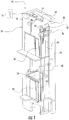
- FIG. 1 shows a schematic view of an elevator assembly 10, in accordance with an embodiment of the disclosure.
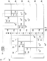
- FIG. 2 shows schematic view of a building elevator system 100, in accordance with an embodiment of the disclosure.
- the elevator assembly 10 includes an elevator car 23 configured to move vertically upward and downward within a hoistway 50 along a plurality of car guide rails 60.
- the elevator assembly 10 also includes a counterweight 28 operably connected to the elevator car 23 via a pulley system 26.
- the counterweight 28 is configured to move vertically upward and downward within the hoistway 50.
- the counterweight 28 moves in a direction generally opposite the movement of the elevator car 23, as is known in conventional elevator assemblies. Movement of the counterweight 28 is guided by counterweight guide rails 70 mounted within the hoistway 50.
- the elevator assembly 10 also includes a power source 12.
- the power is provided from the power source 12 to a switch panel 14, which may include circuit breakers, meters, etc. From the switch panel 14, the power may be provided directly to the drive unit 20 through the controller 30 or to an internal power source charger 16, which converts AC power to direct current (DC) power to charge an internal power source 18 that requires charging.
- an internal power source 18 that requires charging may be a battery, capacitor, or any other type of power storage device known to one of ordinary skill in the art.
- the internal power source 18 may not require charging from the external power source 12 and may be a device such as, for example a gas powered generator, solar cells, hydroelectric generator, wind turbine generator or similar power generation device.
- the internal power source 18 may power various components of the elevator assembly 10 when an external power source is unavailable.
- the drive unit 20 drives a machine 22 to impart motion to the elevator car 23 via a traction sheave of the machine 22.
- the machine 22 also includes a brake 24 that can be activated to stop the machine 22 and elevator car 23.
- FIG. 1 depicts a machine room-less elevator assembly 10, however the embodiments disclosed herein may be incorporated with other elevator assemblics that are not machine room-less or that include any other known elevator configuration.
- elevator systems having more than one independently operating elevator car in each elevator shaft and/or ropeless elevator systems may also be used.
- the elevator car may have two or more compartments.
- the controller 30 is responsible for controlling the operation of the elevator assembly 10.
- the controller 30 is tied to a control system 110 ( FIG. 2 ), which is responsible for controlling multiple elevator assemblies and will be discussed below.
- the controller 30 may also determine a mode (motoring, regenerative, near balance) of the elevator car 23.
- the controller 30 may use the car direction and the weight distribution between the elevator car 23 and the counterweight 28 to determine the mode of the elevator car 23.
- the controller 30 may adjust the velocity of the elevator car 23 to reach a target floor.
- the controller 30 may include a processor and an associated memory.
- the processor may be, but is not limited to, a single-processor or multi-processor system of any of a wide array of possible architectures, including field programmable gate array (FPGA), central processing unit (CPU), application specific integrated circuits (ASIC), digital signal processor (DSP) or graphics processing unit (GPU) hardware arranged homogenously or heterogeneously.
- the memory may be but is not limited to a random access memory (RAM), read only memory (ROM), or other electronic, optical, magnetic or any other computer readable medium.
- a building elevator system 100 within a building 102 may include multiple different individual elevators assemblies 10a-10f.
- the elevator assemblies 10 may be divided up into two or more elevator systems 92a, 92b.
- multiple elevator systems 92a, 92b may be used to get occupants to their destination faster and more efficiently.
- Multiple elevator systems 92a, 92b may also exist in shorter building for various other reasons including but not limited to, efficiency.
- FIG. 2 includes a first elevator system 92a and a second elevator system 92b.
- each elevator system 92a, 92b typically overlap at a transfer floor (ex: sky lobby), so that occupants may disembark one elevator system and enter another. Buildings may have multiple transfer floors including a first transfer floor and a second transfer floor. As seen in FIG. 2 , the floor coverage of the first elevator system 92a overlaps the floor coverage of the second elevator system 92b at floor 80d, which is considered the transfer floor.
- Each elevator system 92a, 92b may have one or more elevator assemblies 10a-10f having elevator cars 23a-23f in an elevator hoistway 50a-50d. In an embodiment, the first elevator system 92a is at a higher elevation than the second elevator system 92b.
- first elevator system 92a serves floors 80d-80f and the second elevator system 92b serves floors 80a-80d.
- the building of FIG. 2 is depicted with six floors, a building may have any desired number of floors.
- the second elevator system 92b and first elevator system 92a may each serve any number of independent and overlapping floors as desired.
- Each floor 80a-80f in the building 102 of FIG. 2 may have an elevator call button 89a-89f and an evacuation alarm 88a-88f.
- the elevator call button 89a-89f sends an elevator call to the control system 110.
- the elevator call button 89a-89f may be a push button and/or a touch screen and may be activated manually or automatically.
- the elevator call button 89a-89f may be activated by a building occupant pushing the elevator call button 89a-89f.
- the elevator call button 89a-89f may also be activated voice recognition or a passenger detection mechanism in the hallway, such as, for example a weight sensing device, a visual recognition device, and a laser detection device.
- the evacuation alarm 88a-88f may be activated or deactivated either manually or automatically through a fire alarm system. If the evacuation alarm 88a-88f is activated, an evacuation call is sent to the controller system 110 indicating the respective floor 80a-80f where the evacuation alarm 88a-88f was activated. In the example of FIG. 2 , an evacuation alarm 88f is activated and floor 88d is the evacuation floor.
- elevator cars 23a-23c of the first elevator system 92a may be carrying occupants to the transfer floor for evacuation and the control system 110 may send elevator cars 23d-23f of the second elevator system 92b to the transfer floor to receive the occupants exiting the elevator cars 23a-23c of the first elevator system 92a and, thereby, return them to the ground floor (or any other desired evacuation floor) for evacuation.
- the ground floor may be floor 80a.
- the control system 110 is operably connected to the controller 30 of each elevator assembly 10.
- the control system 110 is configured to the control and coordinate operation of multiple elevator systems 92a, 92b.
- the control system 110 may be an electronic controller including a processor and an associated memory comprising computer-executable instructions that, when executed by the processor, cause the processor to perform various operations.
- the processor may be, but is not limited to, a single-processor or multi-processor system of any of a wide array of possible architectures, including field programmable gate array (FPGA), central processing unit (CPU), application specific integrated circuits (ASIC), digital signal processor (DSP) or graphics processing unit (GPU) hardware arranged homogenously or heterogeneously.
- the memory may be but is not limited to a random access memory (RAM), read only memory (ROM), or other electronic, optical, magnetic or any other computer readable medium.
- the elevator systems 92a, 92b may also include a notification device 74 as seen in FIG. 1 , and each elevator system 92a, 92b may include a notification device 74a-74f as seen in FIG. 2 .
- the notification device 74a-74f may be located within the individual elevator cars 23a-23f or on the transfer floor.
- the notification device 74a-74f is in operative communication with the control system 110.
- the notification device 74a-74f is configured to provide transfer instructions to occupants.
- the transfer instructions may describe where on the transfer floor to board an elevator car 23d-23f of the second elevator system 92b when the occupants are disembarking an elevator car 23a-23c of the first elevator system 92a.
- the notification device 74a-74f may provide transfer instructions in audible and/or visual form.
- the elevator assemblies 10a-10f may also include a sensor system 76 configured to detect a number of occupants in a particular elevator car 23, as seen in FIG. 1 .
- the sensor system 76 is also seen in FIG. 2 , as sensor systems 76a-76f.
- the sensor system 76 is in operative communication with the control system 110.
- the sensor system 76 may use a variety of sensing mechanisms such as, for example, a visual detection device, a weight detection device, a laser detection device, a door reversal monitoring device, a thermal image detection device, and a depth detection device.
- the visual detection device may be a camera that utilizes visual recognition to identify and count individual passengers.
- the weight detection device may be a scale to sense the amount of weight in an elevator car 23 and then determine the number of passengers from the weight sensed.
- the laser detection device may detect how many passengers walk through a laser beam to determine the number of passengers in the elevator car 23.
- a door reversal monitoring device also detects passengers entering the car so as not to close the elevator door on a passenger and thus may be used to determine the number of passengers in the elevator car 23.
- the thermal detection device may be an infrared or other heat sensing camera that utilizes detected temperature to identify and count individual passengers.
- the depth detection device may be a 2-D, 3-D or other depth/distance detecting camera that utilizes detected distance to an object to identify and count individual passengers.
- additional methods may exist to sense the number of passengers and one or any combination of these methods may be used to determine the number of passengers in the elevator car.
- determining the number of occupants in an elevator car 23a-23c of the first elevator system 92a approaching the transfer floor may help the control system 110 determine how many elevators cars 23d-23f to send to the transfer floor from the second elevator system 92b.
- the control system 110 is configured to determine the number of occupants in an elevator car 23a-23c of the first elevator system 92a so as to send the appropriate number of elevators cars 23d-23f from the second elevator system 92b to the transfer floor, which will help expedite getting from passengers between the two elevator systems 92a, 92b.
- FIG. 3 shows a flow chart of method 300 of operating a building elevator system 100a-100f, in accordance with an embodiment of the disclosure.
- the building elevator system 100a-100f is under normal operation.
- the control system 110 is controlling the first elevator system 92a and the second elevator system 92b.
- the floor coverage of the first elevator system 92a overlaps the floor coverage of the second elevator system 92b by at least one transfer floor, as seen in FIG. 2 .
- the transfer floor is floor 80d.
- the system controller 110 detects if an evacuation call has been received from an evacuation floor.
- the method 300 will move to block 306.
- the system controller 110 detects when a first elevator car 23a-23c of the first elevator system 92a is dispatched to the transfer floor. Once the first elevator car 23a-23c of the first elevator system 92a has been dispatched to the transfer floor, the control system 110 will determine the projected arrival time of the first elevator car 23a-23c at the transfer floor, at block 308.
- a sensor system 76 detects the number of occupants within the first elevator car 23a-23c of the first elevator system 92a.
- the system controller 110 determines how many elevator cars 23a-23c from the second elevator system 92b need to be sent to the transfer floor in response to the number of occupants detected within the first elevator car 23a-23c of the first elevator system 92a.
- the system controller 110 dispatches at least one elevator car 23d-23f of the second elevator system 92b to the transfer floor.
- the elevator car 23d-23f of the second elevator system 92b is dispatched to arrive at the transfer floor within a selected time period of the projected arrival time of an elevator car 23a-23c of the first elevator system 92a.
- the selected time period may be five seconds. In one embodiment, the selected time period may be greater than or less than five seconds.
- a notification device 74a-74f provides transfer instructions to the occupants of the first elevator car 23a-23c of the first elevator system 92a where on the transfer floor to board the second elevator car 23d-23f of the second elevator system 92b.
- the control system 110 determines if there is a second transfer floor between the transfer floor and a discharge floor.
- a discharge floor may be a floor where occupants can evacuate the building 102.
- the discharge floor may be a ground floor. In the example of FIG. 2 , the discharge floor is 80a.
- the control system 110 will dispatch the elevator car 23 of the second elevator system 92b to the second transfer floor once occupants have transferred from the first elevator car 23a-23c of the first elevator system 92a at block 322 and then return to normal operation at block 304.
- the control system 110 will dispatch the elevator car 23d-23f of the second elevator system 92b to the discharge floor once occupants have transferred from the first elevator car 23a-23c of the first elevator system 92a at block 324 and then return to block operation at block 304.
- embodiments can be in the form of processor-implemented processes and devices for practicing those processes, such as processor.
- Embodiments can also be in the form of computer program code containing instructions embodied in tangible media, such as network cloud storage, SD cards, flash drives, floppy diskettes, CD ROMs, hard drives, or any other computer-readable storage medium, wherein, when the computer program code is loaded into and executed by a computer, the computer becomes a device for practicing the embodiments.
- Embodiments can also be in the form of computer program code, for example, whether stored in a storage medium, loaded into and/or executed by a computer, or transmitted over some transmission medium, loaded into and/or executed by a computer, or transmitted over some transmission medium, such as over electrical wiring or cabling, through fiber optics, or via electromagnetic radiation, wherein, when the computer program code is loaded into an executed by a computer, the computer becomes an device for practicing the embodiments.
- the computer program code segments configure the microprocessor to create specific logic circuits.
Landscapes
- Engineering & Computer Science (AREA)
- Automation & Control Theory (AREA)
- Computer Networks & Wireless Communication (AREA)
- Mechanical Engineering (AREA)
- Civil Engineering (AREA)
- Structural Engineering (AREA)
- Elevator Control (AREA)
- Maintenance And Inspection Apparatuses For Elevators (AREA)
Abstract
Description
- The subject matter disclosed herein relates generally to the field of elevator systems, and specifically to a method and apparatus for coordinating the operation of multiple elevator cars.
- Commonly, very tall buildings (ex: high rise or sky scrapers) require sky lobbies or transfer floors, which are intermediate interchange (i.e. transfer) floors where people may transfer from an elevator serving an upper portion of the building to an elevator serving a lower portion of the building. Sky lobbies pose challenges during an evacuation and a more efficient solution is desired.
- According to one embodiment, a method of operating a building elevator system is provided. The method of operation a building elevator system includes: controlling a first elevator system and a second elevator system, floor coverage of the first elevator system overlapping floor coverage of the second elevator system at a least one transfer floor; receiving an evacuation call from an evacuation floor; detecting when a first elevator car of the first elevator system is dispatched to the transfer floor; and dispatching a second elevator car of the second elevator system to the transfer floor.
- In addition to one or more of the features described above, or as an alternative, further embodiments of the method may include dispatching the second elevator car to a discharge floor after occupants have loaded into the second elevator car on the transfer floor.
- In addition to one or more of the features described above, or as an alternative, further embodiments of the method may include dispatching the second elevator car to a second transfer floor after occupants have loaded into the second elevator car on the transfer floor.
- In addition to one or more of the features described above, or as an alternative, further embodiments of the method may include determining a projected arrival time of the first elevator car at the transfer floor; wherein second elevator car is dispatched to arrive at the transfer floor within a selected time period of the projected arrival time.
- In addition to one or more of the features described above, or as an alternative, further embodiments of the method may include providing, using a notification device, transfer instructions to occupants.
- In addition to one or more of the features described above, or as an alternative, further embodiments of the method may include detecting, using a sensor system, a number of occupants within the first elevator car.
- In addition to one or more of the features described above, or as an alternative, further embodiments of the method may include determining a number of elevators cars from the second elevator system to be dispatched to the transfer floor in response to the number of occupants within the first elevator car.
- According to another embodiment, a control system of a building elevator system is provided. The control system including: a processor; a memory comprising computer-executable instructions that, when executed by the processor, cause the processor to perform operations. The operations include: controlling a first elevator system and a second elevator system, floor coverage of the first elevator system overlapping floor coverage of the second elevator system at a least one transfer floor; receiving an evacuation call from an evacuation floor; detecting when a first elevator car of the first elevator system is dispatched to the transfer floor; and dispatching a second elevator car of the second elevator system to the transfer floor.
- In addition to one or more of the features described above, or as an alternative, further embodiments of the control system may include that the operations further include: dispatching the second elevator car to a discharge floor after occupants have loaded into the second elevator car on the transfer floor.
- In addition to one or more of the features described above, or as an alternative, further embodiments of the control system may include that the operations further include: dispatching the second elevator car to a second transfer floor after occupants have loaded into the second elevator car on the transfer floor.
- In addition to one or more of the features described above, or as an alternative, further embodiments of the control system may include that the operations further include: determining a projected arrival time of the first elevator car at the transfer floor; wherein the second elevator car is dispatched to arrive at the transfer floor within a selected time period of the projected arrival time.
- In addition to one or more of the features described above, or as an alternative, further embodiments of the control system may include that the operations further include: providing, using a notification device, transfer instructions to occupants.
- In addition to one or more of the features described above, or as an alternative, further embodiments of the control system may include that the operations further include: detecting, using a sensor system, a number of occupants within the first elevator car.
- In addition to one or more of the features described above, or as an alternative, further embodiments of the control system may include that the operations further include: determining a number of elevators cars from the second elevator system to be dispatched to the transfer floor in response to the number of occupants within the first elevator car.
- According to another embodiment, a computer program product tangibly embodied on a computer readable medium is provided. The computer program product including instructions that, when executed by a processor, cause the processor to perform operations. The operations includes: controlling a first elevator system and a second elevator system, floor coverage of the first elevator system overlapping floor coverage of the second elevator system at a least one transfer floor; receiving an evacuation call from an evacuation floor; detecting when a first elevator car of the first elevator system is dispatched to the transfer floor; and dispatching a second elevator car of the second elevator system to the transfer floor.
- In addition to one or more of the features described above, or as an alternative, further embodiments of the computer program may include that the operations further include: dispatching the second elevator car to a discharge floor after occupants have loaded into the second elevator car on the transfer floor.
- In addition to one or more of the features described above, or as an alternative, further embodiments of the computer program may include that the operations further include: dispatching the second elevator car to a second transfer floor after occupants have loaded into the second elevator car on the transfer floor.
- In addition to one or more of the features described above, or as an alternative, further embodiments of the computer program may include that the operations further include: determining a projected arrival time of the first elevator car at the transfer floor, wherein the second elevator car is dispatched to arrive at the transfer floor within a selected time period of the projected arrival time.
- In addition to one or more of the features described above, or as an alternative, further embodiments of the computer program may include that the operations further include: providing, using a notification device, transfer instructions to occupants.
- In addition to one or more of the features described above, or as an alternative, further embodiments of the computer program may include that the operations further include: detecting, using a sensor system, a number of occupants within the first elevator car; and determining a number of elevators cars from the second elevator system to be dispatched to the transfer floor in response to the number of occupants within the first elevator car.
- Technical effects of embodiments of the present disclosure include a control system to control the operation of a first elevator system and a second elevator system that share a transfer floor and command an elevator car of the second elevator system to move to the transfer floor to pick up passengers when an elevator car of the first elevator system is dispatched to the transfer floor. Technical effects also include coordinating the transfer of passengers at transfer floor from one elevator car to another elevator car.
- The foregoing features and elements may be combined in various combinations without exclusivity, unless expressly indicated otherwise. These features and elements as well as the operation thereof will become more apparent in light of the following description and the accompanying drawings. It should be understood, however, that the following description and drawings are intended to be illustrative and explanatory in nature and non-limiting.
- The foregoing and other features, and advantages of the disclosure are apparent from the following detailed description taken in conjunction with the accompanying drawings in which like elements are numbered alike in the several FIGURES:
-
FIG. 1 illustrates a schematic view of an elevator assembly, in accordance with an embodiment of the disclosure; -
FIG. 2 illustrates a schematic view of a building elevator system, in accordance with an embodiment of the disclosure; and -
FIG. 3 is a flow chart of method of operating a building elevator system, in accordance with an embodiment of the disclosure. -
FIG. 1 shows a schematic view of anelevator assembly 10, in accordance with an embodiment of the disclosure.FIG. 2 shows schematic view of abuilding elevator system 100, in accordance with an embodiment of the disclosure. With reference toFIG. 1 , theelevator assembly 10 includes anelevator car 23 configured to move vertically upward and downward within ahoistway 50 along a plurality ofcar guide rails 60. Theelevator assembly 10 also includes acounterweight 28 operably connected to theelevator car 23 via apulley system 26. Thecounterweight 28 is configured to move vertically upward and downward within thehoistway 50. Thecounterweight 28 moves in a direction generally opposite the movement of theelevator car 23, as is known in conventional elevator assemblies. Movement of thecounterweight 28 is guided bycounterweight guide rails 70 mounted within thehoistway 50. - The
elevator assembly 10 also includes apower source 12. The power is provided from thepower source 12 to aswitch panel 14, which may include circuit breakers, meters, etc. From theswitch panel 14, the power may be provided directly to thedrive unit 20 through thecontroller 30 or to an internalpower source charger 16, which converts AC power to direct current (DC) power to charge aninternal power source 18 that requires charging. For instance, aninternal power source 18 that requires charging may be a battery, capacitor, or any other type of power storage device known to one of ordinary skill in the art. Alternatively, theinternal power source 18 may not require charging from theexternal power source 12 and may be a device such as, for example a gas powered generator, solar cells, hydroelectric generator, wind turbine generator or similar power generation device. Theinternal power source 18 may power various components of theelevator assembly 10 when an external power source is unavailable. Thedrive unit 20 drives amachine 22 to impart motion to theelevator car 23 via a traction sheave of themachine 22. Themachine 22 also includes abrake 24 that can be activated to stop themachine 22 andelevator car 23. As will be appreciated by those of skill in the art,FIG. 1 depicts a machineroom-less elevator assembly 10, however the embodiments disclosed herein may be incorporated with other elevator assemblics that are not machine room-less or that include any other known elevator configuration. In addition, elevator systems having more than one independently operating elevator car in each elevator shaft and/or ropeless elevator systems may also be used. In one embodiment, the elevator car may have two or more compartments. - The
controller 30 is responsible for controlling the operation of theelevator assembly 10. Thecontroller 30 is tied to a control system 110 (FIG. 2 ), which is responsible for controlling multiple elevator assemblies and will be discussed below. Thecontroller 30 may also determine a mode (motoring, regenerative, near balance) of theelevator car 23. Thecontroller 30 may use the car direction and the weight distribution between theelevator car 23 and thecounterweight 28 to determine the mode of theelevator car 23. Thecontroller 30 may adjust the velocity of theelevator car 23 to reach a target floor. Thecontroller 30 may include a processor and an associated memory. The processor may be, but is not limited to, a single-processor or multi-processor system of any of a wide array of possible architectures, including field programmable gate array (FPGA), central processing unit (CPU), application specific integrated circuits (ASIC), digital signal processor (DSP) or graphics processing unit (GPU) hardware arranged homogenously or heterogeneously. The memory may be but is not limited to a random access memory (RAM), read only memory (ROM), or other electronic, optical, magnetic or any other computer readable medium. - As seen in
FIG. 2 , abuilding elevator system 100 within abuilding 102 may include multiple differentindividual elevators assemblies 10a-10f. Theelevator assemblies 10 may be divided up into two ormore elevator systems floors 80a-80f,multiple elevator systems Multiple elevator systems FIG. 2 includes afirst elevator system 92a and asecond elevator system 92b. Floor coverage of eachelevator system FIG. 2 , the floor coverage of thefirst elevator system 92a overlaps the floor coverage of thesecond elevator system 92b atfloor 80d, which is considered the transfer floor. Eachelevator system more elevator assemblies 10a-10f havingelevator cars 23a-23f in anelevator hoistway 50a-50d. In an embodiment, thefirst elevator system 92a is at a higher elevation than thesecond elevator system 92b. That is, thefirst elevator system 92a servesfloors 80d-80f and thesecond elevator system 92b servesfloors 80a-80d. In order for a passenger fromfloors 80a-80c to reachfloors 80e-80f, they would need to transfer fromsecond elevator system 92b tofirst elevator system 92a atfloor 80d. While the building ofFIG. 2 is depicted with six floors, a building may have any desired number of floors. Moreover, thesecond elevator system 92b andfirst elevator system 92a may each serve any number of independent and overlapping floors as desired. - Each
floor 80a-80f in thebuilding 102 ofFIG. 2 may have anelevator call button 89a-89f and anevacuation alarm 88a-88f. Theelevator call button 89a-89f sends an elevator call to thecontrol system 110. Theelevator call button 89a-89f may be a push button and/or a touch screen and may be activated manually or automatically. For example, theelevator call button 89a-89f may be activated by a building occupant pushing theelevator call button 89a-89f. Theelevator call button 89a-89f may also be activated voice recognition or a passenger detection mechanism in the hallway, such as, for example a weight sensing device, a visual recognition device, and a laser detection device. Theevacuation alarm 88a-88f may be activated or deactivated either manually or automatically through a fire alarm system. If theevacuation alarm 88a-88f is activated, an evacuation call is sent to thecontroller system 110 indicating therespective floor 80a-80f where theevacuation alarm 88a-88f was activated. In the example ofFIG. 2 , anevacuation alarm 88f is activated andfloor 88d is the evacuation floor. - In a building having a
second elevator system 92b and afirst elevator system 92a, in the case of an evacuation,elevator cars 23a-23c of thefirst elevator system 92a may be carrying occupants to the transfer floor for evacuation and thecontrol system 110 may sendelevator cars 23d-23f of thesecond elevator system 92b to the transfer floor to receive the occupants exiting theelevator cars 23a-23c of thefirst elevator system 92a and, thereby, return them to the ground floor (or any other desired evacuation floor) for evacuation. In the example ofFIG. 2 , the ground floor may befloor 80a. - The
control system 110 is operably connected to thecontroller 30 of eachelevator assembly 10. Thecontrol system 110 is configured to the control and coordinate operation ofmultiple elevator systems control system 110 may be an electronic controller including a processor and an associated memory comprising computer-executable instructions that, when executed by the processor, cause the processor to perform various operations. The processor may be, but is not limited to, a single-processor or multi-processor system of any of a wide array of possible architectures, including field programmable gate array (FPGA), central processing unit (CPU), application specific integrated circuits (ASIC), digital signal processor (DSP) or graphics processing unit (GPU) hardware arranged homogenously or heterogeneously. The memory may be but is not limited to a random access memory (RAM), read only memory (ROM), or other electronic, optical, magnetic or any other computer readable medium. - The
elevator systems notification device 74 as seen inFIG. 1 , and eachelevator system notification device 74a-74f as seen inFIG. 2 . Thenotification device 74a-74f may be located within theindividual elevator cars 23a-23f or on the transfer floor. Thenotification device 74a-74f is in operative communication with thecontrol system 110. Thenotification device 74a-74f is configured to provide transfer instructions to occupants. For example, the transfer instructions may describe where on the transfer floor to board anelevator car 23d-23f of thesecond elevator system 92b when the occupants are disembarking anelevator car 23a-23c of thefirst elevator system 92a. Thenotification device 74a-74f may provide transfer instructions in audible and/or visual form. - The
elevator assemblies 10a-10f may also include asensor system 76 configured to detect a number of occupants in aparticular elevator car 23, as seen inFIG. 1 . Thesensor system 76 is also seen inFIG. 2 , assensor systems 76a-76f. Thesensor system 76 is in operative communication with thecontrol system 110. Thesensor system 76 may use a variety of sensing mechanisms such as, for example, a visual detection device, a weight detection device, a laser detection device, a door reversal monitoring device, a thermal image detection device, and a depth detection device. The visual detection device may be a camera that utilizes visual recognition to identify and count individual passengers. The weight detection device may be a scale to sense the amount of weight in anelevator car 23 and then determine the number of passengers from the weight sensed. The laser detection device may detect how many passengers walk through a laser beam to determine the number of passengers in theelevator car 23. Similarly, a door reversal monitoring device also detects passengers entering the car so as not to close the elevator door on a passenger and thus may be used to determine the number of passengers in theelevator car 23. The thermal detection device may be an infrared or other heat sensing camera that utilizes detected temperature to identify and count individual passengers. The depth detection device may be a 2-D, 3-D or other depth/distance detecting camera that utilizes detected distance to an object to identify and count individual passengers. As may be appreciated by one of skill in the art, in addition to the stated methods, additional methods may exist to sense the number of passengers and one or any combination of these methods may be used to determine the number of passengers in the elevator car. - Advantageously, determining the number of occupants in an
elevator car 23a-23c of thefirst elevator system 92a approaching the transfer floor may help thecontrol system 110 determine howmany elevators cars 23d-23f to send to the transfer floor from thesecond elevator system 92b. Thecontrol system 110 is configured to determine the number of occupants in anelevator car 23a-23c of thefirst elevator system 92a so as to send the appropriate number ofelevators cars 23d-23f from thesecond elevator system 92b to the transfer floor, which will help expedite getting from passengers between the twoelevator systems - Referring now to
FIG. 3 , while referencing components ofFIGs. 1 and2 .FIG. 3 shows a flow chart ofmethod 300 of operating a building elevator system 100a-100f, in accordance with an embodiment of the disclosure. Atblock 304, the building elevator system 100a-100f is under normal operation. Under normal operation, thecontrol system 110 is controlling thefirst elevator system 92a and thesecond elevator system 92b. As mentioned above, the floor coverage of thefirst elevator system 92a overlaps the floor coverage of thesecond elevator system 92b by at least one transfer floor, as seen inFIG. 2 . In the example ofFIG. 2 , the transfer floor isfloor 80d. Atblock 305, thesystem controller 110 detects if an evacuation call has been received from an evacuation floor. Atblock 305, if an evacuation call has been received from an evacuation floor then themethod 300 will move to block 306. Atblock 305, if an evacuation call has not been received from an evacuation floor then themethod 300 will move back to block 304. Atblock 306, thesystem controller 110 detects when afirst elevator car 23a-23c of thefirst elevator system 92a is dispatched to the transfer floor. Once thefirst elevator car 23a-23c of thefirst elevator system 92a has been dispatched to the transfer floor, thecontrol system 110 will determine the projected arrival time of thefirst elevator car 23a-23c at the transfer floor, atblock 308. Atblock 310, asensor system 76, detects the number of occupants within thefirst elevator car 23a-23c of thefirst elevator system 92a. Atblock 314, thesystem controller 110 determines howmany elevator cars 23a-23c from thesecond elevator system 92b need to be sent to the transfer floor in response to the number of occupants detected within thefirst elevator car 23a-23c of thefirst elevator system 92a. Atblock 316, thesystem controller 110 dispatches at least oneelevator car 23d-23f of thesecond elevator system 92b to the transfer floor. In an embodiment theelevator car 23d-23f of thesecond elevator system 92b is dispatched to arrive at the transfer floor within a selected time period of the projected arrival time of anelevator car 23a-23c of thefirst elevator system 92a. For instance, if the selected time period is zero then theelevator car 23d-23f of thesecond elevator system 92b is dispatched to arrive at the transfer floor at the same time thefirst elevator car 23a-23c of thefirst elevator system 92a is projected to arrive at the transfer floor. In an embodiment, the selected time period may be five seconds. In one embodiment, the selected time period may be greater than or less than five seconds. - At
block 318, anotification device 74a-74f provides transfer instructions to the occupants of thefirst elevator car 23a-23c of thefirst elevator system 92a where on the transfer floor to board thesecond elevator car 23d-23f of thesecond elevator system 92b. Atblock 320, thecontrol system 110 determines if there is a second transfer floor between the transfer floor and a discharge floor. A discharge floor may be a floor where occupants can evacuate thebuilding 102. For example, in one embodiment the discharge floor may be a ground floor. In the example ofFIG. 2 , the discharge floor is 80a. Atblock 320, if there is a second transfer floor between the transfer floor and a discharge floor, thecontrol system 110 will dispatch theelevator car 23 of thesecond elevator system 92b to the second transfer floor once occupants have transferred from thefirst elevator car 23a-23c of thefirst elevator system 92a atblock 322 and then return to normal operation atblock 304. Atblock 320 if there is not a second transfer floor between the transfer floor and a discharge floor, thecontrol system 110 will dispatch theelevator car 23d-23f of thesecond elevator system 92b to the discharge floor once occupants have transferred from thefirst elevator car 23a-23c of thefirst elevator system 92a atblock 324 and then return to block operation atblock 304. - While the above description has described the flow process of
FIG. 3 in a particular order, it should be appreciated that unless otherwise specifically required in the attached claims that the ordering of the steps may be varied. - As described above, embodiments can be in the form of processor-implemented processes and devices for practicing those processes, such as processor. Embodiments can also be in the form of computer program code containing instructions embodied in tangible media, such as network cloud storage, SD cards, flash drives, floppy diskettes, CD ROMs, hard drives, or any other computer-readable storage medium, wherein, when the computer program code is loaded into and executed by a computer, the computer becomes a device for practicing the embodiments. Embodiments can also be in the form of computer program code, for example, whether stored in a storage medium, loaded into and/or executed by a computer, or transmitted over some transmission medium, loaded into and/or executed by a computer, or transmitted over some transmission medium, such as over electrical wiring or cabling, through fiber optics, or via electromagnetic radiation, wherein, when the computer program code is loaded into an executed by a computer, the computer becomes an device for practicing the embodiments. When implemented on a general-purpose microprocessor, the computer program code segments configure the microprocessor to create specific logic circuits.
- The terminology used herein is for the purpose of describing particular embodiments only and is not intended to be limiting. While the description has been presented for purposes of illustration and description, it is not intended to be exhaustive or limited to embodiments in the form disclosed. Many modifications, variations, alterations, substitutions or equivalent arrangement not hereto described will be apparent to those of ordinary skill in the art without departing from the scope of the disclosure. Additionally, while the various embodiments have been described, it is to be understood that aspects may include only some of the described embodiments. Accordingly, the disclosure is not to be seen as limited by the foregoing description, but is only limited by the scope of the appended claims.
Claims (15)
- A method of operating a building elevator system (100), the method comprising:controlling a first elevator system (92a) and a second elevator system (92b), floor coverage of the first elevator system (92a) overlapping floor coverage of the second elevator system (92b) at a least one transfer floor (80d);receiving an evacuation call from an evacuation floor;detecting when a first elevator car (23) of the first elevator system (92a) is dispatched to the transfer floor (80d); anddispatching a second elevator car (23) of the second elevator system (92b) to the transfer floor (80d).
- The method of claim 1, further comprising:dispatching the second elevator car (23) to a discharge floor (80a) after occupants have loaded into the second elevator car (23) on the transfer floor (80d).
- The method of claim 1 or 2, further comprising:dispatching the second elevator car (239 to a second transfer floor after occupants have loaded into the second elevator car (23) on the transfer floor (80d).
- The method of any of claims 1 to 3, further comprising:determining a projected arrival time of the first elevator car (23) at the transfer floor (80d);wherein the second elevator car (23) is dispatched to arrive at the transfer floor (80d) within a selected time period of the projected arrival time.
- The method of any of claims 1 to 4, further comprising:providing, using a notification device (74), transfer instructions to occupants.
- The method of any of claims 1 to 5, further comprising:detecting, using a sensor system (76), a number of occupants within the first elevator car (23).
- The method of claim 6, further comprising:determining a number of elevators cars (23) from the second elevator system (92b) to be dispatched to the transfer floor (80d) in response to the number of occupants within the first elevator car (23).
- A control system (110) of a building elevator system (100) comprising:a processor;a memory comprising computer-executable instructions that, when executed by the processor, cause the processor to perform operations, the operations comprising:controlling a first elevator system (92a) and a second elevator system (92b), floor coverage of the first elevator system (92a) overlapping floor coverage of the second elevator system (92b9 at a least one transfer floor (80d);receiving an evacuation call from an evacuation floor;detecting when a first elevator car (23) of the first elevator system (92a) is dispatched to the transfer floor (80d); anddispatching a second elevator car (23) of the second elevator system (92b) to the transfer floor (80d).
- The control system of claim 8, wherein the operations further comprise:dispatching the second elevator car (23) to a discharge floor (80a) after occupants have loaded into the second elevator car (23) on the transfer floor (80d).
- The control system of claim 8 or 9, wherein the operations further comprise:dispatching the second elevator car (23) to a second transfer floor after occupants have loaded into the second elevator car (23) on the transfer floor (80d).
- The control system of any of claims 8 to 10, wherein the operations further comprise:determining a projected arrival time of the first elevator car (23) at the transfer floor (80d);wherein the second elevator car (23) is dispatched to arrive at the transfer floor (80d) within a selected time period of the projected arrival time.
- The control system of any of claims 8 to 11, wherein the operations further comprise:providing, using a notification device (74), transfer instructions to occupants.
- The control system of any of claims 8 to 12, wherein the operations further comprise:detecting, using a sensor system (76), a number of occupants within the first elevator car (23).
- The control system of claim 13, wherein the operations further comprise:determining a number of elevators cars (23) from the second elevator system (92b) to be dispatched to the transfer floor (80d) in response to the number of occupants within the first elevator car (23).
- A computer program product tangibly embodied on a computer readable medium, the computer program product including instructions that, when executed by a processor, cause the processor to perform operations to carry out the method according to any of claims 1 to 7.
Applications Claiming Priority (1)
| Application Number | Priority Date | Filing Date | Title |
|---|---|---|---|
| US15/280,121 US20180086598A1 (en) | 2016-09-29 | 2016-09-29 | Group coordination of elevators within a building for occupant evacuation |
Publications (2)
| Publication Number | Publication Date |
|---|---|
| EP3301052A1 true EP3301052A1 (en) | 2018-04-04 |
| EP3301052B1 EP3301052B1 (en) | 2020-04-01 |
Family
ID=59895187
Family Applications (1)
| Application Number | Title | Priority Date | Filing Date |
|---|---|---|---|
| EP17191450.0A Active EP3301052B1 (en) | 2016-09-29 | 2017-09-15 | Group coordination of elevators within a building for occupant evacuation |
Country Status (3)
| Country | Link |
|---|---|
| US (1) | US20180086598A1 (en) |
| EP (1) | EP3301052B1 (en) |
| CN (1) | CN107879209A (en) |
Cited By (1)
| Publication number | Priority date | Publication date | Assignee | Title |
|---|---|---|---|---|
| EP3492416A1 (en) * | 2017-12-04 | 2019-06-05 | Otis Elevator Company | Elevator group management for occupant evacuation |
Families Citing this family (4)
| Publication number | Priority date | Publication date | Assignee | Title |
|---|---|---|---|---|
| US11292690B2 (en) | 2018-07-25 | 2022-04-05 | Otis Elevator Company | Capacity shifting between partially-overlapping elevator groups |
| CN110304503B (en) * | 2019-07-24 | 2021-05-25 | 上海三菱电梯有限公司 | Elevator transfer system |
| CN110708518B (en) * | 2019-11-05 | 2021-05-25 | 北京深测科技有限公司 | People flow analysis early warning dispersion method and system |
| CN116307655B (en) * | 2023-05-25 | 2023-08-08 | 西南交通大学 | Evacuation elevator dispatching strategy optimization method, device, equipment and readable storage medium |
Citations (3)
| Publication number | Priority date | Publication date | Assignee | Title |
|---|---|---|---|---|
| US20110155516A1 (en) * | 2009-12-31 | 2011-06-30 | Inventio Ag | Method of Operating Elevators During Emergency Situations |
| JP2011131969A (en) * | 2009-12-22 | 2011-07-07 | Toshiba Elevator Co Ltd | Rescue operation system for elevator |
| WO2015189458A1 (en) * | 2014-06-12 | 2015-12-17 | Kone Corporation | Method for using an elevator system and elevator system |
Family Cites Families (12)
| Publication number | Priority date | Publication date | Assignee | Title |
|---|---|---|---|---|
| JPS599468B2 (en) * | 1977-10-06 | 1984-03-02 | 三菱電機株式会社 | Elevator group control device |
| JPH07137946A (en) * | 1993-11-17 | 1995-05-30 | Toshiba Corp | Elevator control device |
| US5785153A (en) * | 1995-11-29 | 1998-07-28 | Otis Elevator Company | Synchronizing elevator arrival at a level of a building |
| US5823299A (en) * | 1996-06-19 | 1998-10-20 | Otis Elevator Company | Shuttle elevators feeding local elevators |
| JP4606570B2 (en) * | 2000-11-22 | 2011-01-05 | 東芝エレベータ株式会社 | Elevator group management control device |
| SG119203A1 (en) * | 2002-12-13 | 2006-02-28 | Inventio Ag | Method and device for controlling a zonally operated elevator installation |
| FI113755B (en) * | 2003-01-31 | 2004-06-15 | Kone Corp | Method of controlling lifts in building, involves performing change between lifts of group serving different zones, on transfer floor selected from preset transfer floors overlapping with different zones |
| SG111198A1 (en) * | 2003-10-09 | 2005-05-30 | Inventio Ag | Lift installation for zonal operation in a building, method for zonal operation of such a lift installation and method for modernisation of a lift installation |
| FI20080640L (en) * | 2008-11-28 | 2010-05-29 | Kone Corp | Elevator system |
| JP5550302B2 (en) * | 2009-10-19 | 2014-07-16 | 東芝エレベータ株式会社 | Elevator rescue operation system |
| FI125122B (en) * | 2010-02-01 | 2015-06-15 | Kone Corp | Elevator system |
| DE102014201804A1 (en) * | 2014-01-31 | 2015-08-06 | Thyssenkrupp Elevator Ag | Method for operating an elevator system |
-
2016
- 2016-09-29 US US15/280,121 patent/US20180086598A1/en not_active Abandoned
-
2017
- 2017-09-15 EP EP17191450.0A patent/EP3301052B1/en active Active
- 2017-09-28 CN CN201710902874.XA patent/CN107879209A/en active Pending
Patent Citations (3)
| Publication number | Priority date | Publication date | Assignee | Title |
|---|---|---|---|---|
| JP2011131969A (en) * | 2009-12-22 | 2011-07-07 | Toshiba Elevator Co Ltd | Rescue operation system for elevator |
| US20110155516A1 (en) * | 2009-12-31 | 2011-06-30 | Inventio Ag | Method of Operating Elevators During Emergency Situations |
| WO2015189458A1 (en) * | 2014-06-12 | 2015-12-17 | Kone Corporation | Method for using an elevator system and elevator system |
Cited By (1)
| Publication number | Priority date | Publication date | Assignee | Title |
|---|---|---|---|---|
| EP3492416A1 (en) * | 2017-12-04 | 2019-06-05 | Otis Elevator Company | Elevator group management for occupant evacuation |
Also Published As
| Publication number | Publication date |
|---|---|
| EP3301052B1 (en) | 2020-04-01 |
| US20180086598A1 (en) | 2018-03-29 |
| CN107879209A (en) | 2018-04-06 |
Similar Documents
| Publication | Publication Date | Title |
|---|---|---|
| EP3301052B1 (en) | Group coordination of elevators within a building for occupant evacuation | |
| EP3354612B1 (en) | Elevator service person collision protection system | |
| EP3299324B1 (en) | Elevator dynamic displays for messaging and communication | |
| EP3450375B1 (en) | Work area technician warning system | |
| US20180093861A1 (en) | Enhanced elevator status information provisions for fire alarm systems | |
| EP3336031A1 (en) | Information preview for elevator passengers | |
| EP3882208A1 (en) | Elevator calling coordination for robots and individuals | |
| EP3228572A1 (en) | Uninterrupted rescue operation | |
| EP3882198B1 (en) | Elevator system crowd detection by robot | |
| US20180093854A1 (en) | Occupant evacuation operation display | |
| EP3492416B1 (en) | Elevator group management for occupant evacuation | |
| EP3309103A1 (en) | Method for occupant evacuation operation utilizing multi-compartment elevators | |
| EP3210923A1 (en) | Advanced smooth rescue operation | |
| US10294075B2 (en) | Re-dispatching unoccupied elevator car for occupant evacuation operation | |
| EP3301054B1 (en) | Optimized occupant evacuation operation by utilizing remaining capacity for multi-copartment elevators | |
| EP3882199A2 (en) | Specialized, personalized and enhanced elevator calling for robots & co-bots | |
| EP3912946A1 (en) | Passenger waiting assessment system | |
| CN113003328A (en) | Control of elevator group to and from | |
| EP4324779A2 (en) | Self intelligent occupant evacuation systems |
Legal Events
| Date | Code | Title | Description |
|---|---|---|---|
| PUAI | Public reference made under article 153(3) epc to a published international application that has entered the european phase |
Free format text: ORIGINAL CODE: 0009012 |
|
| STAA | Information on the status of an ep patent application or granted ep patent |
Free format text: STATUS: THE APPLICATION HAS BEEN PUBLISHED |
|
| AK | Designated contracting states |
Kind code of ref document: A1 Designated state(s): AL AT BE BG CH CY CZ DE DK EE ES FI FR GB GR HR HU IE IS IT LI LT LU LV MC MK MT NL NO PL PT RO RS SE SI SK SM TR |
|
| AX | Request for extension of the european patent |
Extension state: BA ME |
|
| STAA | Information on the status of an ep patent application or granted ep patent |
Free format text: STATUS: REQUEST FOR EXAMINATION WAS MADE |
|
| 17P | Request for examination filed |
Effective date: 20181004 |
|
| RBV | Designated contracting states (corrected) |
Designated state(s): AL AT BE BG CH CY CZ DE DK EE ES FI FR GB GR HR HU IE IS IT LI LT LU LV MC MK MT NL NO PL PT RO RS SE SI SK SM TR |
|
| GRAP | Despatch of communication of intention to grant a patent |
Free format text: ORIGINAL CODE: EPIDOSNIGR1 |
|
| STAA | Information on the status of an ep patent application or granted ep patent |
Free format text: STATUS: GRANT OF PATENT IS INTENDED |
|
| INTG | Intention to grant announced |
Effective date: 20191118 |
|
| GRAS | Grant fee paid |
Free format text: ORIGINAL CODE: EPIDOSNIGR3 |
|
| GRAA | (expected) grant |
Free format text: ORIGINAL CODE: 0009210 |
|
| STAA | Information on the status of an ep patent application or granted ep patent |
Free format text: STATUS: THE PATENT HAS BEEN GRANTED |
|
| AK | Designated contracting states |
Kind code of ref document: B1 Designated state(s): AL AT BE BG CH CY CZ DE DK EE ES FI FR GB GR HR HU IE IS IT LI LT LU LV MC MK MT NL NO PL PT RO RS SE SI SK SM TR |
|
| REG | Reference to a national code |
Ref country code: GB Ref legal event code: FG4D |
|
| REG | Reference to a national code |
Ref country code: CH Ref legal event code: EP Ref country code: AT Ref legal event code: REF Ref document number: 1251110 Country of ref document: AT Kind code of ref document: T Effective date: 20200415 |
|
| REG | Reference to a national code |
Ref country code: DE Ref legal event code: R096 Ref document number: 602017013889 Country of ref document: DE |
|
| REG | Reference to a national code |
Ref country code: IE Ref legal event code: FG4D |
|
| PG25 | Lapsed in a contracting state [announced via postgrant information from national office to epo] |
Ref country code: BG Free format text: LAPSE BECAUSE OF FAILURE TO SUBMIT A TRANSLATION OF THE DESCRIPTION OR TO PAY THE FEE WITHIN THE PRESCRIBED TIME-LIMIT Effective date: 20200701 |
|
| REG | Reference to a national code |
Ref country code: NL Ref legal event code: MP Effective date: 20200401 |
|
| REG | Reference to a national code |
Ref country code: LT Ref legal event code: MG4D |
|
| PG25 | Lapsed in a contracting state [announced via postgrant information from national office to epo] |
Ref country code: SE Free format text: LAPSE BECAUSE OF FAILURE TO SUBMIT A TRANSLATION OF THE DESCRIPTION OR TO PAY THE FEE WITHIN THE PRESCRIBED TIME-LIMIT Effective date: 20200401 Ref country code: IS Free format text: LAPSE BECAUSE OF FAILURE TO SUBMIT A TRANSLATION OF THE DESCRIPTION OR TO PAY THE FEE WITHIN THE PRESCRIBED TIME-LIMIT Effective date: 20200801 Ref country code: FI Free format text: LAPSE BECAUSE OF FAILURE TO SUBMIT A TRANSLATION OF THE DESCRIPTION OR TO PAY THE FEE WITHIN THE PRESCRIBED TIME-LIMIT Effective date: 20200401 Ref country code: NO Free format text: LAPSE BECAUSE OF FAILURE TO SUBMIT A TRANSLATION OF THE DESCRIPTION OR TO PAY THE FEE WITHIN THE PRESCRIBED TIME-LIMIT Effective date: 20200701 Ref country code: GR Free format text: LAPSE BECAUSE OF FAILURE TO SUBMIT A TRANSLATION OF THE DESCRIPTION OR TO PAY THE FEE WITHIN THE PRESCRIBED TIME-LIMIT Effective date: 20200702 Ref country code: LT Free format text: LAPSE BECAUSE OF FAILURE TO SUBMIT A TRANSLATION OF THE DESCRIPTION OR TO PAY THE FEE WITHIN THE PRESCRIBED TIME-LIMIT Effective date: 20200401 Ref country code: PT Free format text: LAPSE BECAUSE OF FAILURE TO SUBMIT A TRANSLATION OF THE DESCRIPTION OR TO PAY THE FEE WITHIN THE PRESCRIBED TIME-LIMIT Effective date: 20200817 Ref country code: CZ Free format text: LAPSE BECAUSE OF FAILURE TO SUBMIT A TRANSLATION OF THE DESCRIPTION OR TO PAY THE FEE WITHIN THE PRESCRIBED TIME-LIMIT Effective date: 20200401 Ref country code: NL Free format text: LAPSE BECAUSE OF FAILURE TO SUBMIT A TRANSLATION OF THE DESCRIPTION OR TO PAY THE FEE WITHIN THE PRESCRIBED TIME-LIMIT Effective date: 20200401 |
|
| REG | Reference to a national code |
Ref country code: AT Ref legal event code: MK05 Ref document number: 1251110 Country of ref document: AT Kind code of ref document: T Effective date: 20200401 |
|
| PG25 | Lapsed in a contracting state [announced via postgrant information from national office to epo] |
Ref country code: LV Free format text: LAPSE BECAUSE OF FAILURE TO SUBMIT A TRANSLATION OF THE DESCRIPTION OR TO PAY THE FEE WITHIN THE PRESCRIBED TIME-LIMIT Effective date: 20200401 Ref country code: RS Free format text: LAPSE BECAUSE OF FAILURE TO SUBMIT A TRANSLATION OF THE DESCRIPTION OR TO PAY THE FEE WITHIN THE PRESCRIBED TIME-LIMIT Effective date: 20200401 Ref country code: HR Free format text: LAPSE BECAUSE OF FAILURE TO SUBMIT A TRANSLATION OF THE DESCRIPTION OR TO PAY THE FEE WITHIN THE PRESCRIBED TIME-LIMIT Effective date: 20200401 |
|
| PG25 | Lapsed in a contracting state [announced via postgrant information from national office to epo] |
Ref country code: AL Free format text: LAPSE BECAUSE OF FAILURE TO SUBMIT A TRANSLATION OF THE DESCRIPTION OR TO PAY THE FEE WITHIN THE PRESCRIBED TIME-LIMIT Effective date: 20200401 |
|
| REG | Reference to a national code |
Ref country code: DE Ref legal event code: R097 Ref document number: 602017013889 Country of ref document: DE |
|
| PG25 | Lapsed in a contracting state [announced via postgrant information from national office to epo] |
Ref country code: SM Free format text: LAPSE BECAUSE OF FAILURE TO SUBMIT A TRANSLATION OF THE DESCRIPTION OR TO PAY THE FEE WITHIN THE PRESCRIBED TIME-LIMIT Effective date: 20200401 Ref country code: IT Free format text: LAPSE BECAUSE OF FAILURE TO SUBMIT A TRANSLATION OF THE DESCRIPTION OR TO PAY THE FEE WITHIN THE PRESCRIBED TIME-LIMIT Effective date: 20200401 Ref country code: EE Free format text: LAPSE BECAUSE OF FAILURE TO SUBMIT A TRANSLATION OF THE DESCRIPTION OR TO PAY THE FEE WITHIN THE PRESCRIBED TIME-LIMIT Effective date: 20200401 Ref country code: DK Free format text: LAPSE BECAUSE OF FAILURE TO SUBMIT A TRANSLATION OF THE DESCRIPTION OR TO PAY THE FEE WITHIN THE PRESCRIBED TIME-LIMIT Effective date: 20200401 Ref country code: ES Free format text: LAPSE BECAUSE OF FAILURE TO SUBMIT A TRANSLATION OF THE DESCRIPTION OR TO PAY THE FEE WITHIN THE PRESCRIBED TIME-LIMIT Effective date: 20200401 Ref country code: AT Free format text: LAPSE BECAUSE OF FAILURE TO SUBMIT A TRANSLATION OF THE DESCRIPTION OR TO PAY THE FEE WITHIN THE PRESCRIBED TIME-LIMIT Effective date: 20200401 Ref country code: RO Free format text: LAPSE BECAUSE OF FAILURE TO SUBMIT A TRANSLATION OF THE DESCRIPTION OR TO PAY THE FEE WITHIN THE PRESCRIBED TIME-LIMIT Effective date: 20200401 |
|
| PLBE | No opposition filed within time limit |
Free format text: ORIGINAL CODE: 0009261 |
|
| STAA | Information on the status of an ep patent application or granted ep patent |
Free format text: STATUS: NO OPPOSITION FILED WITHIN TIME LIMIT |
|
| PG25 | Lapsed in a contracting state [announced via postgrant information from national office to epo] |
Ref country code: SK Free format text: LAPSE BECAUSE OF FAILURE TO SUBMIT A TRANSLATION OF THE DESCRIPTION OR TO PAY THE FEE WITHIN THE PRESCRIBED TIME-LIMIT Effective date: 20200401 Ref country code: PL Free format text: LAPSE BECAUSE OF FAILURE TO SUBMIT A TRANSLATION OF THE DESCRIPTION OR TO PAY THE FEE WITHIN THE PRESCRIBED TIME-LIMIT Effective date: 20200401 |
|
| 26N | No opposition filed |
Effective date: 20210112 |
|
| REG | Reference to a national code |
Ref country code: CH Ref legal event code: PL |
|
| PG25 | Lapsed in a contracting state [announced via postgrant information from national office to epo] |
Ref country code: SI Free format text: LAPSE BECAUSE OF FAILURE TO SUBMIT A TRANSLATION OF THE DESCRIPTION OR TO PAY THE FEE WITHIN THE PRESCRIBED TIME-LIMIT Effective date: 20200401 |
|
| REG | Reference to a national code |
Ref country code: BE Ref legal event code: MM Effective date: 20200930 |
|
| PG25 | Lapsed in a contracting state [announced via postgrant information from national office to epo] |
Ref country code: LU Free format text: LAPSE BECAUSE OF NON-PAYMENT OF DUE FEES Effective date: 20200915 |
|
| PG25 | Lapsed in a contracting state [announced via postgrant information from national office to epo] |
Ref country code: IE Free format text: LAPSE BECAUSE OF NON-PAYMENT OF DUE FEES Effective date: 20200915 Ref country code: LI Free format text: LAPSE BECAUSE OF NON-PAYMENT OF DUE FEES Effective date: 20200930 Ref country code: BE Free format text: LAPSE BECAUSE OF NON-PAYMENT OF DUE FEES Effective date: 20200930 Ref country code: CH Free format text: LAPSE BECAUSE OF NON-PAYMENT OF DUE FEES Effective date: 20200930 |
|
| GBPC | Gb: european patent ceased through non-payment of renewal fee |
Effective date: 20210915 |
|
| PG25 | Lapsed in a contracting state [announced via postgrant information from national office to epo] |
Ref country code: TR Free format text: LAPSE BECAUSE OF FAILURE TO SUBMIT A TRANSLATION OF THE DESCRIPTION OR TO PAY THE FEE WITHIN THE PRESCRIBED TIME-LIMIT Effective date: 20200401 Ref country code: MT Free format text: LAPSE BECAUSE OF FAILURE TO SUBMIT A TRANSLATION OF THE DESCRIPTION OR TO PAY THE FEE WITHIN THE PRESCRIBED TIME-LIMIT Effective date: 20200401 Ref country code: CY Free format text: LAPSE BECAUSE OF FAILURE TO SUBMIT A TRANSLATION OF THE DESCRIPTION OR TO PAY THE FEE WITHIN THE PRESCRIBED TIME-LIMIT Effective date: 20200401 |
|
| PG25 | Lapsed in a contracting state [announced via postgrant information from national office to epo] |
Ref country code: MK Free format text: LAPSE BECAUSE OF FAILURE TO SUBMIT A TRANSLATION OF THE DESCRIPTION OR TO PAY THE FEE WITHIN THE PRESCRIBED TIME-LIMIT Effective date: 20200401 Ref country code: MC Free format text: LAPSE BECAUSE OF FAILURE TO SUBMIT A TRANSLATION OF THE DESCRIPTION OR TO PAY THE FEE WITHIN THE PRESCRIBED TIME-LIMIT Effective date: 20200401 |
|
| PG25 | Lapsed in a contracting state [announced via postgrant information from national office to epo] |
Ref country code: GB Free format text: LAPSE BECAUSE OF NON-PAYMENT OF DUE FEES Effective date: 20210915 |
|
| PGFP | Annual fee paid to national office [announced via postgrant information from national office to epo] |
Ref country code: FR Payment date: 20230822 Year of fee payment: 7 Ref country code: DE Payment date: 20230822 Year of fee payment: 7 |