EP3300952A1 - Variable interior lighting device for vehicle - Google Patents
Variable interior lighting device for vehicle Download PDFInfo
- Publication number
- EP3300952A1 EP3300952A1 EP17193501.8A EP17193501A EP3300952A1 EP 3300952 A1 EP3300952 A1 EP 3300952A1 EP 17193501 A EP17193501 A EP 17193501A EP 3300952 A1 EP3300952 A1 EP 3300952A1
- Authority
- EP
- European Patent Office
- Prior art keywords
- lens
- optical
- light
- variable
- orientation
- Prior art date
- Legal status (The legal status is an assumption and is not a legal conclusion. Google has not performed a legal analysis and makes no representation as to the accuracy of the status listed.)
- Withdrawn
Links
Images


Classifications
-
- F—MECHANICAL ENGINEERING; LIGHTING; HEATING; WEAPONS; BLASTING
- F21—LIGHTING
- F21V—FUNCTIONAL FEATURES OR DETAILS OF LIGHTING DEVICES OR SYSTEMS THEREOF; STRUCTURAL COMBINATIONS OF LIGHTING DEVICES WITH OTHER ARTICLES, NOT OTHERWISE PROVIDED FOR
- F21V5/00—Refractors for light sources
- F21V5/04—Refractors for light sources of lens shape
-
- B—PERFORMING OPERATIONS; TRANSPORTING
- B60—VEHICLES IN GENERAL
- B60Q—ARRANGEMENT OF SIGNALLING OR LIGHTING DEVICES, THE MOUNTING OR SUPPORTING THEREOF OR CIRCUITS THEREFOR, FOR VEHICLES IN GENERAL
- B60Q3/00—Arrangement of lighting devices for vehicle interiors; Lighting devices specially adapted for vehicle interiors
- B60Q3/70—Arrangement of lighting devices for vehicle interiors; Lighting devices specially adapted for vehicle interiors characterised by the purpose
- B60Q3/76—Arrangement of lighting devices for vehicle interiors; Lighting devices specially adapted for vehicle interiors characterised by the purpose for spotlighting, e.g. reading lamps
-
- B—PERFORMING OPERATIONS; TRANSPORTING
- B60—VEHICLES IN GENERAL
- B60Q—ARRANGEMENT OF SIGNALLING OR LIGHTING DEVICES, THE MOUNTING OR SUPPORTING THEREOF OR CIRCUITS THEREFOR, FOR VEHICLES IN GENERAL
- B60Q3/00—Arrangement of lighting devices for vehicle interiors; Lighting devices specially adapted for vehicle interiors
- B60Q3/60—Arrangement of lighting devices for vehicle interiors; Lighting devices specially adapted for vehicle interiors characterised by optical aspects
-
- B—PERFORMING OPERATIONS; TRANSPORTING
- B60—VEHICLES IN GENERAL
- B60Q—ARRANGEMENT OF SIGNALLING OR LIGHTING DEVICES, THE MOUNTING OR SUPPORTING THEREOF OR CIRCUITS THEREFOR, FOR VEHICLES IN GENERAL
- B60Q3/00—Arrangement of lighting devices for vehicle interiors; Lighting devices specially adapted for vehicle interiors
- B60Q3/80—Circuits; Control arrangements
-
- F—MECHANICAL ENGINEERING; LIGHTING; HEATING; WEAPONS; BLASTING
- F21—LIGHTING
- F21V—FUNCTIONAL FEATURES OR DETAILS OF LIGHTING DEVICES OR SYSTEMS THEREOF; STRUCTURAL COMBINATIONS OF LIGHTING DEVICES WITH OTHER ARTICLES, NOT OTHERWISE PROVIDED FOR
- F21V19/00—Fastening of light sources or lamp holders
-
- F—MECHANICAL ENGINEERING; LIGHTING; HEATING; WEAPONS; BLASTING
- F21—LIGHTING
- F21V—FUNCTIONAL FEATURES OR DETAILS OF LIGHTING DEVICES OR SYSTEMS THEREOF; STRUCTURAL COMBINATIONS OF LIGHTING DEVICES WITH OTHER ARTICLES, NOT OTHERWISE PROVIDED FOR
- F21V23/00—Arrangement of electric circuit elements in or on lighting devices
- F21V23/003—Arrangement of electric circuit elements in or on lighting devices the elements being electronics drivers or controllers for operating the light source, e.g. for a LED array
-
- F—MECHANICAL ENGINEERING; LIGHTING; HEATING; WEAPONS; BLASTING
- F21—LIGHTING
- F21V—FUNCTIONAL FEATURES OR DETAILS OF LIGHTING DEVICES OR SYSTEMS THEREOF; STRUCTURAL COMBINATIONS OF LIGHTING DEVICES WITH OTHER ARTICLES, NOT OTHERWISE PROVIDED FOR
- F21V5/00—Refractors for light sources
- F21V5/04—Refractors for light sources of lens shape
- F21V5/045—Refractors for light sources of lens shape the lens having discontinuous faces, e.g. Fresnel lenses
-
- F—MECHANICAL ENGINEERING; LIGHTING; HEATING; WEAPONS; BLASTING
- F21—LIGHTING
- F21V—FUNCTIONAL FEATURES OR DETAILS OF LIGHTING DEVICES OR SYSTEMS THEREOF; STRUCTURAL COMBINATIONS OF LIGHTING DEVICES WITH OTHER ARTICLES, NOT OTHERWISE PROVIDED FOR
- F21V5/00—Refractors for light sources
- F21V5/08—Refractors for light sources producing an asymmetric light distribution
-
- G—PHYSICS
- G02—OPTICS
- G02B—OPTICAL ELEMENTS, SYSTEMS OR APPARATUS
- G02B26/00—Optical devices or arrangements for the control of light using movable or deformable optical elements
- G02B26/004—Optical devices or arrangements for the control of light using movable or deformable optical elements based on a displacement or a deformation of a fluid
- G02B26/005—Optical devices or arrangements for the control of light using movable or deformable optical elements based on a displacement or a deformation of a fluid based on electrowetting
-
- G—PHYSICS
- G02—OPTICS
- G02B—OPTICAL ELEMENTS, SYSTEMS OR APPARATUS
- G02B3/00—Simple or compound lenses
- G02B3/12—Fluid-filled or evacuated lenses
- G02B3/14—Fluid-filled or evacuated lenses of variable focal length
-
- F—MECHANICAL ENGINEERING; LIGHTING; HEATING; WEAPONS; BLASTING
- F21—LIGHTING
- F21V—FUNCTIONAL FEATURES OR DETAILS OF LIGHTING DEVICES OR SYSTEMS THEREOF; STRUCTURAL COMBINATIONS OF LIGHTING DEVICES WITH OTHER ARTICLES, NOT OTHERWISE PROVIDED FOR
- F21V14/00—Controlling the distribution of the light emitted by adjustment of elements
- F21V14/003—Controlling the distribution of the light emitted by adjustment of elements by interposition of elements with electrically controlled variable light transmissivity, e.g. liquid crystal elements or electrochromic devices
-
- F—MECHANICAL ENGINEERING; LIGHTING; HEATING; WEAPONS; BLASTING
- F21—LIGHTING
- F21V—FUNCTIONAL FEATURES OR DETAILS OF LIGHTING DEVICES OR SYSTEMS THEREOF; STRUCTURAL COMBINATIONS OF LIGHTING DEVICES WITH OTHER ARTICLES, NOT OTHERWISE PROVIDED FOR
- F21V14/00—Controlling the distribution of the light emitted by adjustment of elements
- F21V14/04—Controlling the distribution of the light emitted by adjustment of elements by movement of reflectors
Definitions
- the invention relates to the field of lighting, especially indoor lighting including motor vehicles.
- the published patent document EP 2 676 843 A1 discloses an individual lighting device for a vehicle seat.
- the device comprises several light sources each emitting in a preferred direction.
- the lighting produced by this device can be modulated by varying the intensity of the light sources.
- This device has the advantage of being simple and economical construction. The modulation it provides however turns out to be coarse in that it is limited to the geometry of the different beams which is fixed.
- the invention aims to overcome at least one drawback of the state of the art mentioned above. More particularly, the invention aims to provide a lighting device that allows a more fine variation of the light beam, in a simple and reliable manner.
- the subject of the invention is an interior lighting device for a vehicle, especially a vehicle, comprising: at least one light source; an optical projection device adapted to be supplied with light by the light source (s) and to form a light beam of variable geometry; remarkable in that the projection optical device is configured to have a variable focal length.
- Optical devices having a variable focal length usually have at least one optical surface of variable geometry.
- Some technological advances predict the appearance of lenses with variable focus without variable geometry.
- an electric field (standing wave) or a liquid crystal phase spatial modulator can create a variable index gradient lens with constant geometry.
- optical surface with variable geometry is meant that the shape and / or orientation of the surface in question is variable.
- the or at least one of the optical surfaces with variable geometry is a face, preferably of exit, of a lens, said face having a variable radius of curvature.
- the lens comprises a liquid transparent optical material in a chamber.
- the lens comprises an elastically deformable wall in contact with the transparent liquid optical material, the radius of curvature of said wall being variable by displacement of said material relative to the chamber.
- the displacement of the liquid transparent optical material is operated by applying a magnetic field.
- the liquid transparent material may in particular be a material based on polymer, water, oil, liquid crystal and / or silicone.
- the lens comprises a chamber containing two different transparent liquid optical materials in direct contact with each other to form a diopter, the chamber comprising a hydrophobic side wall in contact with the two materials, and electrodes configured to enable an electric field to be applied between one of said materials and said wall to modify the wetting of said wall and said material, modifying said wetting which modifies the diopter radius of curvature.
- the two different liquid transparent optical materials are respectively water and oil.
- the variation of curvature of the face of the lens makes it possible to vary the angular field of the light beam.
- the lens is configured and arranged so that the variation of geometry, preferably of the curvature, of the face of said lens makes it possible to vary the orientation of the light beam.
- the projection optical device comprises a shaping lens arranged between the light source (s) and the lens with at least one of the optical surfaces with variable geometry, said shaping lens being configured to form a light beam, preferably convergent, from the light produced by the light source or sources.
- the or at least one of the variable geometry optical surfaces comprises a microsystem with at least one micro-mirror whose orientation is electrically actuated.
- the projection optical device further comprises an optical element, such as a bi-convergent lens, capable of focusing the light emitted by the light source (s) towards the mirror (s).
- an optical element such as a bi-convergent lens
- the projection optical device further comprises a projection lens adapted to receive the light reflected by the one or more micro-mirrors and to form the light beam.
- the actuation of the orientation of the micromirror (s) makes it possible to vary the orientation of the light beam.
- the device comprises the micro-mirror microsystem (s) and the lens with the variable radius-of-curvature face, said lens being arranged to receive the light reflected by the micro-mirror (s). mirrors.
- the optical projection device advantageously the one or more optical surfaces with variable geometry, is electrically actuatable so as to vary the focal length, the orientation and / or the opening of the light beam can be varied by an electrical control signal.
- the measurements of the invention are interesting in that they confer on the luminous device a capacity to adapt the opening and / or the orientation of the light beam, in particular according to the needs of the persons concerned.
- This adaptation is achieved by electrical control without an electromechanical device external potentially potentially bulky and subject to failure is necessary.
- the curvature variation of an input or output face of a lens takes place within a closed and compact enclosure.
- the pivoting of the micromirror (s) of a microsystem takes place within the system and is a primary function of said system.
- the level of integration of the solution of the invention namely to vary the geometry of at least one optical surface within the light device, is high and thus provides a compactness, simplicity and reliability of the device.
- the Figures 1 and 2 illustrate an interior lighting device according to a first embodiment.
- the figure 1 schematically illustrates the device and the figure 2 the implantation of the device inside a vehicle and the variation of the light beam.
- the lighting device 2 comprises a housing 4 housing one or more light sources 6.
- the light source 6 illuminates essentially in a half-space delimited by the plane of its support, along the optical axis 8 of the device 2.
- the latter also comprises an optical projection device 10 adapted to receive the light emitted by the light source 6 and to form a lighting beam.
- the optical device 10 may comprise a first lens 12 for shaping the beam produced by the light source 6. This lens 12 is advantageously of the convergent type. It makes it possible to deflect the rays emitted in the half-space by the light source 6 into a diverging beam of lesser opening.
- the optical device 10 comprises a second lens 14 with variable geometry. More precisely, at least one of the input 14.1 and output 14.2 faces has a variable curvature. In the example of the figure 1 it is the output face 14.2 which has a variable curvature.
- the curvature variation is schematically represented by a first regular dashed profile, said profile being generally straight, and a second irregular dashed profile (axis type), said profile being curved so as to form a face convex.
- the beam produced when the lens 14 is in the configuration where its output face 14.2 is generally flat is shown in regular broken lines. It should be noted that this planar configuration is for example, it being understood that it could be a curved configuration. Similarly, the beam produced when the lens 14 is in the configuration where its exit face 14.2 is convex is illustrated in irregular broken lines. It can be seen that the flat configuration of the exit face 14.2 produces a wider beam than the convex configuration of said face.
- the lens may comprise a main optical material which is liquid and delimited by an elastically deformable wall.
- the elastically deformable wall corresponds to the exit face 14.2.
- the liquid optical material is contained in a chamber of the lens.
- the curvature of the outlet face formed by the deformable wall may be varied by moving a portion of the liquid optical material out of or toward the chamber. This movement can in particular be achieved by an electromagnetic actuator acting on an elastic wall portion of the chamber.
- Such lenses are commercially available, in particular from the company Optotune®.
- the lens may also comprise two different liquid optical materials and in contact with each other forming a diopter.
- One of the materials may be water and the other oil. These materials are contained in a chamber of which one side wall, at one of the two materials, has a hydrophobic coating in contact with said material. This wall portion forms a first electrode while a second electrode is in contact with the liquid optical material in contact with the wall forming the first electrode.
- Applying an electrical voltage to the electrodes will generate an electric field in the liquid material, at its contact with the hydrophobic coating.
- This electric field will then modify the wetting of the coating in question by the material, in accordance with the well known principle of electrowetting ("electrowetting" in English).
- This wetting variation will modify the meniscus formed by the material in contact with the wall in question and the other material. This modification will cause a change in the curvature of the diopter between the two materials.
- Such lenses are commercially available from Varioptic®.
- the figure 2 illustrates the implementation of the lighting device 2 of the figure 1 in a vehicle 16, more precisely on the roof flag 18 above a row of seats 20, such as a row of rear seats.
- the lighting device is placed above the right seat (on the left in the figure).
- the Figures 3 and 4 illustrate an interior lighting device according to a second embodiment.
- the figure 3 schematically illustrates the device and the figure 4 the implantation of the device inside a vehicle and the variation of the light beam.
- the reference numbers of the first embodiment are used to designate identical or corresponding elements in the second embodiment, these numbers being however increased by 100. Reference is also made to the description of these elements in relation to the Figures 1 and 2 . Specific reference numbers between 100 and 200 are used to designate the specific elements.
- the lighting device 102 comprises a housing 104 housing a light source and an optical projection device 110.
- the light source 106 is arranged to illuminate along a first optical axis 107 transverse to a second optical axis 108 corresponding to the optical axis of the light. output of the device.
- the first optical axis 107 may form with the second optical axis 108 an angle of between 60 ° and 90 °, preferably between 70 ° and 90 °.
- the optical projection device 110 comprises a first lens 112 disposed on the first optical axis 107.
- This lens 112 is of the convergent type in order to focus the light emitted by the light source 106 towards an electromechanical microsystem 113 comprising a micro-mirror or a matrix micro-mirrors.
- electromechanical microsystems are commonly referred to as DMD, the acronym for the English expression Digital Micro System.
- These electromechanical microsystems allow the projection of a digital image by reflection on micro-mirrors that can switch between 2 different positions. The inclination of each of these positions, with respect to a reference direction corresponding to the second optical axis 108, may be between 10 ° and 15 °. The scanning angle can then be between 20 ° and 30 °.
- MOEMS optoelectromechanical microsystem
- MEMS micro-electro-mechanical systems
- MEMS Micro-Electro-Mechanical Systems
- the optical projection device 110 comprises a second lens 115 disposed along the second optical axis 108, so as to receive the light reflected by the microsystem 113.
- This lens 115 is advantageously a projection lens so as to widen the beam coming from the microsystem 113
- the exit face 115.2 of the lens 115 is advantageously curved and convex.
- the light beam will be oriented on one side or the other of the second optical axis 108, as can be seen in FIG. figure 3 in regular broken lines and irregular broken lines (center line).
- the transition from one position to another can be done binary or continuously with the possibility of choosing one or several intermediate positions.
- the microsystem must be designed to allow such angular positions of the micromirror (s).
- the projection optical device 110 may comprise a zoom lens 114, similar to the lens 14 of the first embodiment ( figure 1 ), that is to say with at least one of the input and output faces whose curvature is variable.
- a zoom lens 114 similar to the lens 14 of the first embodiment ( figure 1 ), that is to say with at least one of the input and output faces whose curvature is variable.
- Such a lens makes it possible to vary the opening of the light beam while the microsystem 113, meanwhile, makes it possible to move the beam by varying its orientation.
- the microsystem is intended to be binary, that is to say present two stable orientations of the micromirror (s)
- the optical projection device 110 it is also conceivable for the optical projection device 110 to comprise two lenses with variable focal lengths arranged, respectively, perpendicular to the optical axes (not shown) of the two beams.
- the projection lens 115 has a variable focal length, similar to the lens 14 of the first embodiment ( figure 1 ).
- the figure 4 illustrates the implementation of the lighting device 102 of the figure 3 in a vehicle 116, more precisely on the roof flag 118 above a row of seats 120, such as a row of rear seats.
- the lighting device is disposed above the central seat and selectively illuminates the left seat or the right seat.
- the lighting device may be arranged differently relative to the seats.
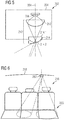
- the Figures 5 and 6 illustrate an interior lighting device according to a third embodiment.
- the figure 5 schematically illustrates the device and the figure 6 the implantation of the device inside a vehicle and the variation of the light beam.
- the reference numbers of the first embodiment are used to denote the same or corresponding elements in the third embodiment, these numbers being however increased by 200. Reference is also made to the description of these elements in relation to the Figures 1 and 2 . Reference numbers between 200 and 300 and distinct from the others are used to designate the specific elements.
- the lighting device 202 comprises a housing 204 housing a light source 206 configured to illuminate along an optical axis 208.
- the lighting device 202 comprises an optical projection device 210.
- This may comprise a first lens 212, similar to the lens 12 of the first embodiment (FIG. figure 1 ). It is a beam forming lens produced by the light source 206.
- This lens 212 is advantageously of the convergent type.
- the optical device 210 comprises a second lens 214 with a variable geometry, similar to the lens 14 of the first embodiment ( figure 1 ). More precisely, at least one of the input 214.1 and output 214.2 faces has a variable curvature. In the example of the figure 5 it is the exit face 214.2 which has a variable curvature.
- the variation of curvature is represented schematically by a first regular dashed profile, said profile being generally convex and symmetrical with respect to the optical axis 208, and a second uneven line profile (axis type), said profile being asymmetrically curved.
- the asymmetrical profile allows to deflect the light rays so as to form a beam inclined relative to the optical axis 208.
- the asymmetrical curvature of one of the input and output faces of the lens 214 in this case the exit face, makes it possible to modify the orientation of the beam.
- the figure 6 illustrates the implementation of the lighting device 202 of the figure 5 in a vehicle 216, more precisely on the roof flag 218 above a row of seats 220, such as a row of rear seats.
- the lighting device is arranged above the left seat (right in the figure). It can be observed that the variation of the curvature of the exit face of the lens of the lighting device makes it possible to change the orientation of the light beam, in this case towards the central seat.
- the lighting devices according to the invention make it possible to adjust the opening and / or the orientation of the light beam produced. They can thus be arranged on a roof of a vehicle roof, alone or in combination, in order to provide adaptive lighting for the occupants of the vehicle.
- a lighting device where the orientation of the light beam is adjustable, it is also possible to provide to control said orientation manually or automatically depending on the displacement of a moving target to be illuminated, such as especially a book.
- control buttons including the "joystick” type can be used.
- the automatic control one or more cameras can be implemented, with an image processing software configured to recognize one or more standard objects, such as a book or a reading tablet.
Abstract
L'invention a trait à un dispositif d'éclairage intérieur (2) pour véhicule notamment automobile, comprenant au moins une source lumineuse (6) ; un dispositif optique de projection (10) apte à être alimenté en lumière par la ou les sources lumineuses (6) et à former un faisceau lumineux à géométrie variable ; le dispositif optique de projection (10) est configuré pour présenter une distance focale variable.The invention relates to an interior lighting device (2) for a vehicle including automobile, comprising at least one light source (6); an optical projection device (10) adapted to be supplied with light by the light source (s) (6) and to form a light beam of variable geometry; the projection optical device (10) is configured to have a variable focal length.
Description
L'invention a trait au domaine de l'éclairage, en particulier de l'éclairage intérieur notamment pour véhicules automobiles.The invention relates to the field of lighting, especially indoor lighting including motor vehicles.
Le document de brevet publié
L'invention a pour objectif de pallier au moins un inconvénient de l'état de l'art susmentionné. Plus particulièrement, l'invention a pour objectif de proposer un dispositif d'éclairage qui permet une variation plus fine du faisceau lumineux, et ce de manière simple et fiable.The invention aims to overcome at least one drawback of the state of the art mentioned above. More particularly, the invention aims to provide a lighting device that allows a more fine variation of the light beam, in a simple and reliable manner.
L'invention a pour objet un dispositif d'éclairage intérieur pour véhicule notamment automobile, comprenant : au moins une source lumineuse ; un dispositif optique de projection apte à être alimenté en lumière par la ou les sources lumineuses et à former un faisceau lumineux à géométrie variable ; remarquable en ce que le dispositif optique de projection est configuré pour présenter une distance focale variable.The subject of the invention is an interior lighting device for a vehicle, especially a vehicle, comprising: at least one light source; an optical projection device adapted to be supplied with light by the light source (s) and to form a light beam of variable geometry; remarkable in that the projection optical device is configured to have a variable focal length.
Les dispositifs optiques présentant une distance focale variable ont habituellement au moins une surface optique à géométrie variable. Certaines avancées technologiques présagent l'apparition de lentilles à focale variable sans géométrie variable. A titre d'exemple, un champ électrique (onde stationnaire) ou un modulateur spatial de phase à cristaux liquide peuvent créer une lentille à gradient d'indice variable avec une géométrie constante.Optical devices having a variable focal length usually have at least one optical surface of variable geometry. Some technological advances predict the appearance of lenses with variable focus without variable geometry. For example, an electric field (standing wave) or a liquid crystal phase spatial modulator can create a variable index gradient lens with constant geometry.
Par surface optique à géométrie variable on entend que la forme et/ou l'orientation de la surface en question est variable.By optical surface with variable geometry is meant that the shape and / or orientation of the surface in question is variable.
Selon un mode avantageux de l'invention, la ou au moins une des surfaces optiques à géométrie variable est une face, préférentiellement de sortie, d'une lentille, ladite face ayant un rayon de courbure variable.According to an advantageous mode of the invention, the or at least one of the optical surfaces with variable geometry is a face, preferably of exit, of a lens, said face having a variable radius of curvature.
Selon un mode avantageux de l'invention, la lentille comprend un matériau optique transparent liquide dans une chambre.According to an advantageous embodiment of the invention, the lens comprises a liquid transparent optical material in a chamber.
Selon un mode avantageux de l'invention, la lentille comprend une paroi déformable élastiquement en contact avec le matériau optique transparent liquide, le rayon de courbure de ladite paroi étant variable par déplacement dudit matériau par rapport à la chambre.According to an advantageous embodiment of the invention, the lens comprises an elastically deformable wall in contact with the transparent liquid optical material, the radius of curvature of said wall being variable by displacement of said material relative to the chamber.
Selon un mode avantageux de l'invention, le déplacement du matériau optique transparent liquide est opéré par application d'un champ magnétique.According to an advantageous embodiment of the invention, the displacement of the liquid transparent optical material is operated by applying a magnetic field.
Le matériau transparent liquide peut notamment être un matériau à base de polymère, d'eau, d'huile, de cristaux liquides et/ou de silicone.The liquid transparent material may in particular be a material based on polymer, water, oil, liquid crystal and / or silicone.
Selon un mode avantageux de l'invention, la lentille comprend une chambre renfermant deux matériaux optiques transparents liquides différents en contact direct l'un avec l'autre pour former un dioptre, la chambre comprenant une paroi latérale hydrophobique en contact avec les deux matériaux, et des électrodes configurées pour permettre d'appliquer un champ électrique entre un desdits matériaux et ladite paroi en vue de modifier le mouillage de la dite paroi et ledit matériau, la modification dudit mouillage modifiant le rayon de courbure du dioptre.According to an advantageous embodiment of the invention, the lens comprises a chamber containing two different transparent liquid optical materials in direct contact with each other to form a diopter, the chamber comprising a hydrophobic side wall in contact with the two materials, and electrodes configured to enable an electric field to be applied between one of said materials and said wall to modify the wetting of said wall and said material, modifying said wetting which modifies the diopter radius of curvature.
Avantageusement, les deux matériaux optiques transparents liquides différents sont respectivement de l'eau et de l'huile.Advantageously, the two different liquid transparent optical materials are respectively water and oil.
Selon un mode avantageux de l'invention, la variation de courbure de la face de la lentille permet de faire varier le champ angulaire du faisceau lumineux.According to an advantageous embodiment of the invention, the variation of curvature of the face of the lens makes it possible to vary the angular field of the light beam.
Selon un mode avantageux de l'invention, la lentille est configurée et disposée de manière à ce que la variation de géométrie, préférentiellement de la courbure, de la face de ladite lentille permette de faire varier l'orientation du faisceau lumineux.According to an advantageous embodiment of the invention, the lens is configured and arranged so that the variation of geometry, preferably of the curvature, of the face of said lens makes it possible to vary the orientation of the light beam.
Avantageusement, le dispositif optique de projection comprend une lentille de mise en forme disposée entre la ou les sources lumineuses et la lentille avec au moins une des surfaces optiques à géométrie variable, ladite lentille de mise en forme étant configurée pour former un faisceau lumineux, préférentiellement convergent, à partir de la lumière produite par la ou les sources lumineuses.Advantageously, the projection optical device comprises a shaping lens arranged between the light source (s) and the lens with at least one of the optical surfaces with variable geometry, said shaping lens being configured to form a light beam, preferably convergent, from the light produced by the light source or sources.
Selon un mode avantageux de l'invention, la ou au moins une des surfaces optiques à géométrie variable comprend un microsystème avec au moins un micro-miroir dont l'orientation est actionnée électriquement.According to an advantageous embodiment of the invention, the or at least one of the variable geometry optical surfaces comprises a microsystem with at least one micro-mirror whose orientation is electrically actuated.
Selon un mode avantageux de l'invention, le dispositif optique de projection comprend, en outre, un élément optique, tel qu'une lentille bi convergente, apte à focaliser la lumière émise par la ou les sources lumineuses vers le ou les micro miroirs.According to an advantageous embodiment of the invention, the projection optical device further comprises an optical element, such as a bi-convergent lens, capable of focusing the light emitted by the light source (s) towards the mirror (s).
Selon un mode avantageux de l'invention, le dispositif optique de projection comprend, en outre, une lentille de projection apte à recevoir la lumière réfléchie par le ou les micro-miroirs et à former le faisceau lumineux.According to an advantageous embodiment of the invention, the projection optical device further comprises a projection lens adapted to receive the light reflected by the one or more micro-mirrors and to form the light beam.
Selon un mode avantageux de l'invention, l'actionnement de l'orientation du ou des micro-miroirs permet de faire varier l'orientation du faisceau lumineux.According to an advantageous embodiment of the invention, the actuation of the orientation of the micromirror (s) makes it possible to vary the orientation of the light beam.
Selon un mode avantageux de l'invention, le dispositif comprend le microsystème à micro-miroir(s) et la lentille avec la face à rayon de courbure variable, ladite lentille étant disposée de manière à recevoir la lumière réfléchie par le ou les micro-miroirs.According to an advantageous embodiment of the invention, the device comprises the micro-mirror microsystem (s) and the lens with the variable radius-of-curvature face, said lens being arranged to receive the light reflected by the micro-mirror (s). mirrors.
Selon un mode avantageux de l'invention, le dispositif optique de projection, avantageusement la ou les surfaces optiques à géométrie variable, est actionnable électriquement de manière à faire varier la distance focale, l'orientation et/ou l'ouverture du faisceau lumineux pouvant être variée par un signal de commande électrique.According to an advantageous embodiment of the invention, the optical projection device, advantageously the one or more optical surfaces with variable geometry, is electrically actuatable so as to vary the focal length, the orientation and / or the opening of the light beam can be varied by an electrical control signal.
Les mesures de l'invention sont intéressantes en ce qu'elles confèrent au dispositif lumineux une capacité à adapter l'ouverture et/ou l'orientation du faisceau lumineux, notamment en fonction des besoins des personnes concernées. Cette adaptation est réalisée par commande électrique sans pour autant qu'un dispositif électromécanique externe potentiellement encombrant et sujet à défaillance soit nécessaire. En effet, la variation de courbure d'une face d'entrée ou de sortie d'une lentille a lieu au sein d'une enceinte fermée et compacte. Similairement, le pivotement du ou des micro-miroirs d'un microsystème a lieu au sein du système et est une fonction primaire dudit système. Le niveau d'intégration de la solution de l'invention, à savoir de faire varier la géométrie d'au moins une surface optique au sein du dispositif lumineux, est élevée et procure ainsi une compacité, simplicité et fiabilité du dispositif.The measurements of the invention are interesting in that they confer on the luminous device a capacity to adapt the opening and / or the orientation of the light beam, in particular according to the needs of the persons concerned. This adaptation is achieved by electrical control without an electromechanical device external potentially potentially bulky and subject to failure is necessary. Indeed, the curvature variation of an input or output face of a lens takes place within a closed and compact enclosure. Similarly, the pivoting of the micromirror (s) of a microsystem takes place within the system and is a primary function of said system. The level of integration of the solution of the invention, namely to vary the geometry of at least one optical surface within the light device, is high and thus provides a compactness, simplicity and reliability of the device.
D'autres caractéristiques et avantages de la présente invention seront mieux compris à l'aide de la description et des dessins parmi lesquels :
- La
figure 1 est une illustration schématique d'un dispositif d'éclairage selon un premier mode de réalisation de l'invention ; - La
figure 2 illustre la variation du faisceau d'éclairage du dispositif de lafigure 1 disposé au-dessus d'une rangée de sièges dans un véhicule ; - La
figure 3 est une illustration schématique d'un dispositif d'éclairage selon un deuxième mode de réalisation de l'invention ; - La
figure 4 illustre la variation du faisceau d'éclairage du dispositif de lafigure 3 disposé au-dessus d'une rangée de sièges dans un véhicule ; - La
figure 5 est une illustration schématique d'un dispositif d'éclairage selon un troisième mode de réalisation de l'invention ; - La
figure 6 illustre la variation du faisceau d'éclairage du dispositif de lafigure 5 disposé au-dessus d'une rangée de sièges dans un véhicule.
- The
figure 1 is a schematic illustration of a lighting device according to a first embodiment of the invention; - The
figure 2 illustrates the variation of the lighting beam of the device of thefigure 1 disposed over a row of seats in a vehicle; - The
figure 3 is a schematic illustration of a lighting device according to a second embodiment of the invention; - The
figure 4 illustrates the variation of the lighting beam of the device of thefigure 3 disposed over a row of seats in a vehicle; - The
figure 5 is a schematic illustration of a lighting device according to a third embodiment of the invention; - The
figure 6 illustrates the variation of the lighting beam of the device of thefigure 5 disposed over a row of seats in a vehicle.
Les
A la
Le dispositif optique 10 comprend une deuxième lentille 14 à géométrie variable. Plus précisément, au moins une des faces d'entrée 14.1 et de sortie 14.2 présente une courbure variable. Dans l'exemple de la
Le faisceau produit lorsque la lentille 14 est dans la configuration où sa face de sortie 14.2 est généralement plane est illustré en trait interrompu régulier. Il est à noter que cette configuration plane est à titre d'exemple, étant entendu qu'il pourrait s'agir d'une configuration courbe. Similairement, le faisceau produit lorsque la lentille 14 est dans la configuration où sa face de sortie 14.2 est convexe est illustré en trait interrompu irrégulier. On peut observer que la configuration plate de la face de sortie 14.2 produit un faisceau plus large que la configuration convexe de ladite face.The beam produced when the
La lentille peut comprendre un matériau optique principal qui est liquide et délimité par une paroi déformable élastiquement. Dans la configuration de la lentille 14 de la
La lentille peut également comprendre deux matériaux optique liquides différents et en contact l'un avec l'autre en formant un dioptre. L'un des matériaux peut être de l'eau et l'autre de l'huile. Ces matériaux sont contenus dans une chambre dont une paroi latérale, au niveau d'un des deux matériaux, comporte un revêtement hydrophobique en contact avec ledit matériau. Cette portion de paroi forme une première électrode alors qu'une deuxième électrode est en contact avec le matériau optique liquide en contact avec la paroi formant la première électrode. Le fait d'appliquer une tension électrique aux électrodes va générer un champ électrique dans le matériau liquide, au niveau de son contact avec le revêtement hydrophobique. Ce champ électrique va alors modifier le mouillage du revêtement en question par le matériau, conformément au principe bien connu en soi d'électro-mouillage (« electrowetting » en anglais). Cette variation de mouillage va modifier le ménisque formé par le matériau au contact de la paroi en question et de l'autre matériau. Cette modification va entrainer un changement de courbure du dioptre entre les deux matériaux. De telles lentilles sont commercialement disponibles auprès de la société Varioptic®.The lens may also comprise two different liquid optical materials and in contact with each other forming a diopter. One of the materials may be water and the other oil. These materials are contained in a chamber of which one side wall, at one of the two materials, has a hydrophobic coating in contact with said material. This wall portion forms a first electrode while a second electrode is in contact with the liquid optical material in contact with the wall forming the first electrode. Applying an electrical voltage to the electrodes will generate an electric field in the liquid material, at its contact with the hydrophobic coating. This electric field will then modify the wetting of the coating in question by the material, in accordance with the well known principle of electrowetting ("electrowetting" in English). This wetting variation will modify the meniscus formed by the material in contact with the wall in question and the other material. This modification will cause a change in the curvature of the diopter between the two materials. Such lenses are commercially available from Varioptic®.
La
Les
Le dispositif d'éclairage 102 comprend un boîtier 104 logeant une source lumineuse et un dispositif optique de projection 110. La source lumineuse 106 est disposée pour éclairer suivant un premier axe optique 107 transversal à un deuxième axe optique 108 correspondant à l'axe optique de sortie du dispositif. Le premier axe optique 107 peut former avec le deuxième axe optique 108 un angle compris entre 60° et 90°, préférentiellement entre 70° et 90°. Le dispositif optique de projection 110 comprend une première lentille 112 disposée sur le premier axe optique 107. Cette lentille 112 est du type convergent afin de focaliser la lumière émise par la source lumineuse 106 vers un microsystème électromécanique 113 comprenant un micro-miroir ou une matrice de micro-miroirs. De tels microsystèmes sont couramment désignés DMD, acronyme de l'expression anglo-saxonne Digital Micro System. Ces microsystèmes électromécaniques permettent la projection d'une image numérique par réflexion sur des micro-miroirs qui peuvent basculer entre 2 positions différentes. L'inclinaison de chacune de ces positions, par rapport à une direction de référence correspondant au deuxième axe optique 108, peut être comprise entre 10° et 15°. L'angle de balayage peut alors être compris entre 20° et 30°. De manière plus générale, il peut s'agir d'un microsystème opto-électro-mécanique ou MOEMS (acronyme de l'expression anglo-saxonne « Micro-Opto-Electro-Mechanical Systems »). Il s'agit d'un sous-ensemble des systèmes micro-électro-mécaniques ou MEMS (« Micro-Electro-Mechanical Systems »). Les MOEMS sont capables de capter ou de manipuler des signaux optiques à une échelle très petite, utilisant des systèmes mécaniques ou électriques intégrés.The
Le dispositif optique de projection 110 comprend une deuxième lentille 115 disposée le long du deuxième axe optique 108, de manière à recevoir la lumière réfléchie par microsystème 113. Cette lentille 115 est avantageusement une lentille de projection de manière à élargir le faisceau provenant du microsystème 113.. La face de sortie 115.2 de la lentille 115 est avantageusement courbée et convexe.The
En fonction de la position angulaire du ou des micro-miroirs sur le microsystème 113, le faisceau lumineux sera orienté d'un côté ou de l'autre du deuxième axe optique 108, comme cela est visible à la
Toujours en référence à la
La
Les
En référence à la
Le dispositif optique 210 comprend une deuxième lentille 214 à géométrie variable, similaire à la lentille 14 du premier mode de réalisation (
La
De manière générale, les dispositifs d'éclairage selon l'invention permettent d'ajuster l'ouverture et/ou l'orientation du faisceau lumineux produit. Ils peuvent ainsi être disposé sur un pavillon de toit de véhicule, seuls ou en combinaison, afin de pouvoir assurer un éclairage adaptatif pour les occupants du véhicule.In general, the lighting devices according to the invention make it possible to adjust the opening and / or the orientation of the light beam produced. They can thus be arranged on a roof of a vehicle roof, alone or in combination, in order to provide adaptive lighting for the occupants of the vehicle.
Dans le cas d'un dispositif d'éclairage où l'orientation du faisceau lumineux est ajustable, il est par ailleurs possible de prévoir de commander ladite orientation de manière manuelle ou encore automatique en fonction du déplacement d'une cible mobile à éclairer, comme notamment un livre. Pour la commande manuelle, des boutons de commande, notamment du type « joystick » peuvent être utilisés. Pour la commande automatique, une ou plusieurs caméras peuvent être mises en oeuvre, avec un logiciel de traitement d'image configuré pour reconnaître un ou plusieurs objets types, tels qu'un livre ou une tablette de lecture.In the case of a lighting device where the orientation of the light beam is adjustable, it is also possible to provide to control said orientation manually or automatically depending on the displacement of a moving target to be illuminated, such as especially a book. For manual control, control buttons, including the "joystick" type can be used. For the automatic control, one or more cameras can be implemented, with an image processing software configured to recognize one or more standard objects, such as a book or a reading tablet.
Claims (15)
le dispositif optique de projection (10 ; 110 ; 210) est configuré pour présenter une distance focale variable.Interior lighting device (2; 102; 202) for a vehicle (16; 116; 216) in particular an automobile, comprising:
the projection optical device (10; 110; 210) is configured to have a variable focal length.
Applications Claiming Priority (1)
| Application Number | Priority Date | Filing Date | Title |
|---|---|---|---|
| FR1659248A FR3056497A1 (en) | 2016-09-28 | 2016-09-28 | VARIABLE INTERIOR LIGHTING DEVICE FOR VEHICLE |
Publications (1)
| Publication Number | Publication Date |
|---|---|
| EP3300952A1 true EP3300952A1 (en) | 2018-04-04 |
Family
ID=57860986
Family Applications (1)
| Application Number | Title | Priority Date | Filing Date |
|---|---|---|---|
| EP17193501.8A Withdrawn EP3300952A1 (en) | 2016-09-28 | 2017-09-27 | Variable interior lighting device for vehicle |
Country Status (4)
| Country | Link |
|---|---|
| US (1) | US20180086257A1 (en) |
| EP (1) | EP3300952A1 (en) |
| CN (1) | CN107869668A (en) |
| FR (1) | FR3056497A1 (en) |
Families Citing this family (3)
| Publication number | Priority date | Publication date | Assignee | Title |
|---|---|---|---|---|
| FR3090523B1 (en) * | 2018-12-19 | 2021-01-01 | Valeo Comfort & Driving Assistance | Lighting device for vehicle ceiling light |
| CN112984455A (en) * | 2021-03-09 | 2021-06-18 | 西安电子科技大学芜湖研究院 | Novel follow-up steering headlamp module |
| DE102021112500A1 (en) | 2021-05-12 | 2022-11-17 | Bayerische Motoren Werke Aktiengesellschaft | Lighting device for a motor vehicle |
Citations (7)
| Publication number | Priority date | Publication date | Assignee | Title |
|---|---|---|---|---|
| DE10107842A1 (en) * | 2001-02-16 | 2002-09-05 | Erco Leuchten | Building lamp for illuminating building surfaces including housing and at least one light source connected to voltage supply also light conducting elements arranged in light path of light source esp. at least 1 lens element, etc. |
| US20080205075A1 (en) * | 2005-07-08 | 2008-08-28 | Koninklijke Philips Electronics, N.V. | Light Module For Producing Light With a Scattering Pattern That is Electrically Variable and Use Thereof as a Multiple Purpose Light |
| JP2011233433A (en) * | 2010-04-28 | 2011-11-17 | Panasonic Electric Works Co Ltd | Lighting system |
| WO2012027851A1 (en) * | 2010-09-02 | 2012-03-08 | Optotune Ag | Illumination source with variable divergence |
| DE102011079012A1 (en) * | 2011-07-12 | 2013-01-17 | Ledon Oled Lighting Gmbh & Co. Kg | Light module with controllable light control |
| US20130063953A1 (en) * | 2011-09-13 | 2013-03-14 | Den-Hua Lee | Light-emitting diode structure |
| DE102015203887A1 (en) * | 2015-03-04 | 2016-09-08 | Hella Kgaa Hueck & Co. | lighting device |
-
2016
- 2016-09-28 FR FR1659248A patent/FR3056497A1/en not_active Withdrawn
-
2017
- 2017-09-27 EP EP17193501.8A patent/EP3300952A1/en not_active Withdrawn
- 2017-09-28 US US15/718,716 patent/US20180086257A1/en not_active Abandoned
- 2017-09-28 CN CN201710900320.6A patent/CN107869668A/en active Pending
Patent Citations (7)
| Publication number | Priority date | Publication date | Assignee | Title |
|---|---|---|---|---|
| DE10107842A1 (en) * | 2001-02-16 | 2002-09-05 | Erco Leuchten | Building lamp for illuminating building surfaces including housing and at least one light source connected to voltage supply also light conducting elements arranged in light path of light source esp. at least 1 lens element, etc. |
| US20080205075A1 (en) * | 2005-07-08 | 2008-08-28 | Koninklijke Philips Electronics, N.V. | Light Module For Producing Light With a Scattering Pattern That is Electrically Variable and Use Thereof as a Multiple Purpose Light |
| JP2011233433A (en) * | 2010-04-28 | 2011-11-17 | Panasonic Electric Works Co Ltd | Lighting system |
| WO2012027851A1 (en) * | 2010-09-02 | 2012-03-08 | Optotune Ag | Illumination source with variable divergence |
| DE102011079012A1 (en) * | 2011-07-12 | 2013-01-17 | Ledon Oled Lighting Gmbh & Co. Kg | Light module with controllable light control |
| US20130063953A1 (en) * | 2011-09-13 | 2013-03-14 | Den-Hua Lee | Light-emitting diode structure |
| DE102015203887A1 (en) * | 2015-03-04 | 2016-09-08 | Hella Kgaa Hueck & Co. | lighting device |
Also Published As
| Publication number | Publication date |
|---|---|
| CN107869668A (en) | 2018-04-03 |
| US20180086257A1 (en) | 2018-03-29 |
| FR3056497A1 (en) | 2018-03-30 |
Similar Documents
| Publication | Publication Date | Title |
|---|---|---|
| FR3065784B1 (en) | LUMINOUS MODULE WITH OPTICAL IMAGING OPTICS FOR A PIXELLIZED SPATIAL MODULATOR FOR A MOTOR VEHICLE | |
| EP3167226B1 (en) | Lighting module for a motor vehicle | |
| EP3300952A1 (en) | Variable interior lighting device for vehicle | |
| EP3357752B1 (en) | Lighting module of a light beam for a motor vehicle headlight | |
| EP0290347A2 (en) | High output signal light, especially for motor vehicles | |
| EP3190335B1 (en) | Luminous device provided with a curved wavelength conversion element, and headlight comprising such a luminous device | |
| WO2017046157A1 (en) | Light-beam-projecting device comprising a digital screen and headlamp equipped with such a device | |
| EP3999380A1 (en) | Lighting device for a motor vehicle | |
| FR2673007A1 (en) | Device for correcting of the parallax and/or the reflective power of a photo apparatus | |
| EP3604904A1 (en) | Light module comprising an array of light sources and a bifocal optical system | |
| FR2578062A1 (en) | DAY-NIGHT JOINT OBSERVATION APPARATUS | |
| EP0978085A1 (en) | Optoelectronic device for image acquisition, in particular of code bars | |
| EP3301500B1 (en) | Lighting system of a motor vehicle and motor vehicle | |
| EP3857283A1 (en) | Projecting optical system and luminous module for a vehicle | |
| EP3301351A1 (en) | Integral mounting for luminous device with micro-mirror array | |
| EP2853804B1 (en) | Lighting and/or signalling module with a plurality of rotary optical systems | |
| EP0025398B1 (en) | Multiple-field optical system | |
| FR2755749A1 (en) | FLEXIBLE LENS LIGHTING SYSTEM | |
| EP3623222A1 (en) | Compact optical system for motor vehicle passenger compartment | |
| FR3100866A1 (en) | Vehicle headlight | |
| FR3069332B1 (en) | DIFFRACTIVE ILLUMINATION DEVICE WITH INCREASED DIFFRACTION ANGLE | |
| EP3486562B1 (en) | Optisches element für optisches moudul eines fahrzeuges | |
| EP3301497A1 (en) | Motor vehicle lighting module with lens having adjustable focal distance | |
| FR3062458A1 (en) | LIGHT BEAM PROJECTION MODULE FOR LIGHT EMITTING DEVICE OF MOTOR VEHICLE | |
| FR3056486A1 (en) | LIGHTING SYSTEM FOR MOTOR VEHICLE AND MOTOR VEHICLE |
Legal Events
| Date | Code | Title | Description |
|---|---|---|---|
| PUAI | Public reference made under article 153(3) epc to a published international application that has entered the european phase |
Free format text: ORIGINAL CODE: 0009012 |
|
| STAA | Information on the status of an ep patent application or granted ep patent |
Free format text: STATUS: THE APPLICATION HAS BEEN PUBLISHED |
|
| AK | Designated contracting states |
Kind code of ref document: A1 Designated state(s): AL AT BE BG CH CY CZ DE DK EE ES FI FR GB GR HR HU IE IS IT LI LT LU LV MC MK MT NL NO PL PT RO RS SE SI SK SM TR |
|
| AX | Request for extension of the european patent |
Extension state: BA ME |
|
| STAA | Information on the status of an ep patent application or granted ep patent |
Free format text: STATUS: THE APPLICATION IS DEEMED TO BE WITHDRAWN |
|
| 18D | Application deemed to be withdrawn |
Effective date: 20181005 |