EP3300929A1 - Data transmitting device capable of configuring different operating frequencies for use by tire pressure monitoring detector - Google Patents
Data transmitting device capable of configuring different operating frequencies for use by tire pressure monitoring detector Download PDFInfo
- Publication number
- EP3300929A1 EP3300929A1 EP16196852.4A EP16196852A EP3300929A1 EP 3300929 A1 EP3300929 A1 EP 3300929A1 EP 16196852 A EP16196852 A EP 16196852A EP 3300929 A1 EP3300929 A1 EP 3300929A1
- Authority
- EP
- European Patent Office
- Prior art keywords
- ratio
- phase
- frequency
- oscillator
- signal
- Prior art date
- Legal status (The legal status is an assumption and is not a legal conclusion. Google has not performed a legal analysis and makes no representation as to the accuracy of the status listed.)
- Granted
Links
Images


Classifications
-
- G—PHYSICS
- G01—MEASURING; TESTING
- G01L—MEASURING FORCE, STRESS, TORQUE, WORK, MECHANICAL POWER, MECHANICAL EFFICIENCY, OR FLUID PRESSURE
- G01L17/00—Devices or apparatus for measuring tyre pressure or the pressure in other inflated bodies
-
- B—PERFORMING OPERATIONS; TRANSPORTING
- B60—VEHICLES IN GENERAL
- B60C—VEHICLE TYRES; TYRE INFLATION; TYRE CHANGING; CONNECTING VALVES TO INFLATABLE ELASTIC BODIES IN GENERAL; DEVICES OR ARRANGEMENTS RELATED TO TYRES
- B60C23/00—Devices for measuring, signalling, controlling, or distributing tyre pressure or temperature, specially adapted for mounting on vehicles; Arrangement of tyre inflating devices on vehicles, e.g. of pumps or of tanks; Tyre cooling arrangements
- B60C23/02—Signalling devices actuated by tyre pressure
- B60C23/04—Signalling devices actuated by tyre pressure mounted on the wheel or tyre
- B60C23/0408—Signalling devices actuated by tyre pressure mounted on the wheel or tyre transmitting the signals by non-mechanical means from the wheel or tyre to a vehicle body mounted receiver
- B60C23/0422—Signalling devices actuated by tyre pressure mounted on the wheel or tyre transmitting the signals by non-mechanical means from the wheel or tyre to a vehicle body mounted receiver characterised by the type of signal transmission means
- B60C23/0433—Radio signals
- B60C23/0447—Wheel or tyre mounted circuits
- B60C23/0452—Antenna structure, control or arrangement
-
- B—PERFORMING OPERATIONS; TRANSPORTING
- B60—VEHICLES IN GENERAL
- B60C—VEHICLE TYRES; TYRE INFLATION; TYRE CHANGING; CONNECTING VALVES TO INFLATABLE ELASTIC BODIES IN GENERAL; DEVICES OR ARRANGEMENTS RELATED TO TYRES
- B60C23/00—Devices for measuring, signalling, controlling, or distributing tyre pressure or temperature, specially adapted for mounting on vehicles; Arrangement of tyre inflating devices on vehicles, e.g. of pumps or of tanks; Tyre cooling arrangements
- B60C23/02—Signalling devices actuated by tyre pressure
- B60C23/04—Signalling devices actuated by tyre pressure mounted on the wheel or tyre
- B60C23/0408—Signalling devices actuated by tyre pressure mounted on the wheel or tyre transmitting the signals by non-mechanical means from the wheel or tyre to a vehicle body mounted receiver
- B60C23/0422—Signalling devices actuated by tyre pressure mounted on the wheel or tyre transmitting the signals by non-mechanical means from the wheel or tyre to a vehicle body mounted receiver characterised by the type of signal transmission means
- B60C23/0433—Radio signals
- B60C23/0447—Wheel or tyre mounted circuits
- B60C23/0455—Transmission control of wireless signals
-
- B—PERFORMING OPERATIONS; TRANSPORTING
- B60—VEHICLES IN GENERAL
- B60C—VEHICLE TYRES; TYRE INFLATION; TYRE CHANGING; CONNECTING VALVES TO INFLATABLE ELASTIC BODIES IN GENERAL; DEVICES OR ARRANGEMENTS RELATED TO TYRES
- B60C23/00—Devices for measuring, signalling, controlling, or distributing tyre pressure or temperature, specially adapted for mounting on vehicles; Arrangement of tyre inflating devices on vehicles, e.g. of pumps or of tanks; Tyre cooling arrangements
- B60C23/02—Signalling devices actuated by tyre pressure
- B60C23/04—Signalling devices actuated by tyre pressure mounted on the wheel or tyre
- B60C23/0408—Signalling devices actuated by tyre pressure mounted on the wheel or tyre transmitting the signals by non-mechanical means from the wheel or tyre to a vehicle body mounted receiver
- B60C23/0422—Signalling devices actuated by tyre pressure mounted on the wheel or tyre transmitting the signals by non-mechanical means from the wheel or tyre to a vehicle body mounted receiver characterised by the type of signal transmission means
- B60C23/0433—Radio signals
- B60C23/0447—Wheel or tyre mounted circuits
- B60C23/0455—Transmission control of wireless signals
- B60C23/0462—Structure of transmission protocol
-
- H—ELECTRICITY
- H03—ELECTRONIC CIRCUITRY
- H03L—AUTOMATIC CONTROL, STARTING, SYNCHRONISATION OR STABILISATION OF GENERATORS OF ELECTRONIC OSCILLATIONS OR PULSES
- H03L7/00—Automatic control of frequency or phase; Synchronisation
- H03L7/06—Automatic control of frequency or phase; Synchronisation using a reference signal applied to a frequency- or phase-locked loop
- H03L7/08—Details of the phase-locked loop
- H03L7/099—Details of the phase-locked loop concerning mainly the controlled oscillator of the loop
-
- H—ELECTRICITY
- H04—ELECTRIC COMMUNICATION TECHNIQUE
- H04B—TRANSMISSION
- H04B1/00—Details of transmission systems, not covered by a single one of groups H04B3/00 - H04B13/00; Details of transmission systems not characterised by the medium used for transmission
- H04B1/02—Transmitters
- H04B1/04—Circuits
- H04B1/0458—Arrangements for matching and coupling between power amplifier and antenna or between amplifying stages
Definitions
- the present invention relates to data transmitting devices and, more particularly, to a data transmitting device capable of configuring different operating frequencies for use by a tire pressure monitoring detector.
- conventional tire pressure monitoring detectors come in two categories: those operating at a frequency of 315 MHz, and those operating at a frequency of 433.92 MHz.
- the aforesaid two frequencies are intended to match the receiving frequencies of vehicular host computers, respectively, because tire pressure monitoring detectors operating at 315 MHz are inapplicable to vehicular host computers operating at 433.92 MHz, and vice versa.
- a tire pressure monitoring detector were capable of selecting its operating frequency and thus applicable to different types of vehicular host computers, the tire pressure monitoring detector would be popular with consumers.
- US 2014/0306815 A1 discloses a multi-frequency tire pressure monitoring detector which uses a phase locked loop (PLL) 270 to adjust frequencies, as shown in FIG. 2 , and uses a microcontroller to provide a related control function.
- the PLL 270 generates signals of a predetermined frequency each under the control of the microcontroller 250, and then the signals are sent to two RF matching circuits 220, 225 at the back end according to their frequencies, respectively. Afterward, the matched circuit sends the signals to an antenna 230 whereby the signals are sent out wirelessly.
- FIG. 3 of US 2014/0306815 A1 shows the fine structures disposed between the PLL and the two matching circuits.
- Paragraphs [0026] ⁇ [0029] in the specification of US 2014/0306815 A1 disclose an operating technique of selecting a frequency of 315 MHz and a frequency of 433.92 MHz and selecting a matching circuit.
- Paragraph [0029] in the specification of US 2014/0306815 A1 discloses using a programmable logic function 330 to open or close a first switch 335 or a second switch 340, so as to select a matching circuit.
- the aforesaid prior art involves using a PLL to provide a frequency of 315 MHz and a frequency of 433.92 MHz for a user to select therebetween.
- the aforesaid two frequencies are achieved not only with the pressure-controlling oscillator of the PLL, but also with two oscillators 310, 350 (shown in FIG 3 ) by frequency multiplication.
- the aforesaid technique which is based on the use of two oscillators, incurs high costs and requires advanced technology.
- data of the microcontroller of US 2014/0306815 A1 is transmitted with the PLL and the matching circuit; as a result, not only are data transmission-related components and routes intricate, but the data transmission is also susceptible to interference.
- Another objective of the present invention is to provide a data transmitting device capable of configuring different operating frequencies for use by a tire pressure monitoring detector such that its data is sent directly from a microcontrol unit to a signal output unit for outward transmission but is not sent through a phase locked loop.
- the present invention provides a data transmitting device capable of configuring different operating frequencies for use by a tire pressure monitoring detector, comprising: a standard oscillator for providing an oscillation signal of a fixed frequency and using the fixed frequency as a standard frequency; a phase locked loop comprising a phase frequency comparator, a filter, and a pressure-controlling oscillator, with the phase frequency comparator being electrically connected to the standard oscillator, the filter being electrically connected to the phase frequency comparator, and the pressure-controlling oscillator being electrically connected to the filter, wherein the pressure-controlling oscillator has an output end electrically connected to the phase frequency comparator; a microcontrol unit electrically connected to the standard oscillator and the phase frequency comparator and adapted to store a first ratio and a second ratio; and a signal output unit electrically connected to the output end of the pressure-controlling oscillator and the microcontrol unit, wherein the microcontrol unit allows a user to select the first ratio or the second ratio and sends the first
- the present invention enables a user to determine the operating frequency of a tire pressure monitoring detector and thus match the tire pressure monitoring detector and different vehicular host computers, thereby allowing the tire pressure monitoring detector to be applicable to vehicular host computers of different specifications. Furthermore, in addition to the pressure-controlling oscillator of a phase locked loop, the present invention uses only one standard oscillator to configure different operating frequencies, thereby cutting costs. Another advantage of the present invention is the lowering of technological hurdles by sparing the need to coordinate two oscillators operating at different frequencies.
- a preferred embodiment of the present invention provides a data transmitting device 10 capable of configuring different operating frequencies for use by a tire pressure monitoring detector, essentially comprising a standard oscillator 11, a phase locked loop 21, a microcontrol unit 31, and a signal output unit 41.
- the standard oscillator 11 provides an oscillation signal of a fixed frequency and uses the fixed frequency as a standard frequency.
- the phase locked loop (PLL) 21 comprises a phase frequency comparator 22, a filter 24, and a pressure-controlling oscillator 26.
- the phase frequency comparator 22 is electrically connected to the standard oscillator 11.
- the filter 24 is electrically connected to the phase frequency comparator 22.
- the pressure-controlling oscillator 26 is electrically connected to the filter 24.
- the pressure-controlling oscillator 26 has an output end 261 which is electrically connected to the phase frequency comparator 22.
- the microcontrol unit 31 is electrically connected to the standard oscillator 11 and the phase frequency comparator 22.
- the microcontrol unit 31 stores a first ratio C1 and a second ratio C2.
- the signal output unit 41 is electrically connected to the output end 261 of the pressure-controlling oscillator 26 and the microcontrol unit 31.
- the microcontrol unit 31 allows a user to select the first ratio C1 or the second ratio C2.
- the microcontrol unit 31 sends the first ratio C1 or the second ratio C2 selected by the user to the phase frequency comparator 22. If the user selects the first ratio C1, it means the user wants to set the operating frequency to 315 MHz. If the user selects the second ratio C2, it means the user wants to set the operating frequency to 433.92 MHz. Before the user selects the first ratio C1 or the second ratio C2, the microcontrol unit 31 uses the first ratio CI as the default ratio.
- the phase locked loop 21 receives an oscillation signal from the standard oscillator I1, generates a target frequency signal Ts according to the first ratio C1 or the second ratio C2 selected by the user, and sends the target frequency signal Ts from the output end 261 to the phase frequency comparator 22 and the signal output unit 41.
- the microcontrol unit 31 sends a data D to the signal output unit 41.
- the signal output unit 41 outputs the data D according to the frequency of the target frequency signal Ts.
- the standard oscillator 11 is a single component independent of the microcontrol unit 31 or an oscillation component integrated into the microcontrol unit 31.
- the phase frequency comparator 22 sends a phase-locked signal Ls to the microcontrol unit 31, so as to determine whether the target frequency signal Ts generated from the phase locked loop 21 has achieved the required frequency. However, if the phase frequency comparator 22 does not send the phase-locked signal Ls to the microcontrol unit 31, it will still be feasible to wait for a specific period of time (generally around 50 milliseconds) before the phase locked loop 21 enters the phase-locked state.
- the signal output unit 41 outputs the data D outward according to the frequency of the target frequency signal Ts, and the recipient is another wireless transmitting device.
- the signal output unit 41 it is also feasible for the signal output unit 41 not to output the data D to another wireless transmitting device; instead, the signal output unit 41 further has a variable impedance antenna 42 whose impedance is adjusted to match the frequency of the target frequency signal Ts, allowing the data D to be wirelessly transmitted outward through the variable impedance antenna 42 at the frequency.
- the user since the first and second ratios C1, C2 are indicative of the user's preference to set the operating frequency to 315 MHz and 433.92 MHz, respectively, to set the operating frequency to 315 MHz, the user either uses the microcontrol unit 31 to select the first ratio C1 or allows the microcontrol unit 31 to use the first ratio C1 as the default ratio, and then the microcontrol unit 31 sends the first ratio C1 to the phase frequency comparator 22.
- the phase locked loop 21 starts to operate according to the first ratio C1 and eventually enters the phase-locked state, whereas the target frequency signal Ts output from the output end 261 of the pressure-controlling oscillator 26 indicates a frequency of 315 MHz.
- the microcontrol unit 31 sends the data D to the signal output unit 41, allowing the signal output unit 41 to output the data D outward at a frequency of 315 MHz.
- the signal output unit 41 has the variable impedance antenna 42
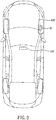
- the impedance of the variable impedance antenna 42 can be adjusted to therefore match a frequency of 315 MHz, allowing the data D to be wirelessly output outward. Therefore, as shown in FIG. 2 , the tire pressure monitoring detector 100 operates at a frequency of 315 MHz and sends the tire pressure status to a vehicular host computer 110, effectuating tire pressure monitoring.
- the user uses the microcontrol unit 31 to select and send the second ratio C2 to the phase frequency comparator 22 such that the phase locked loop 21 starts to operate according to the second ratio C2 and eventually enters the phase-locked state, and in consequence the target frequency signal Ts output from the output end 261 of the pressure-controlling oscillator 26 indicates a frequency of 433.92 MHz.
- the microcontrol unit 31 sends the data D to the signal output unit 41, and therefore the signal output unit 41 outputs the data D outward at a frequency of 433.92 MHz.
- the impedance of the variable impedance antenna 42 can be adjusted to therefore match a frequency of 433.92 MHz, allowing the data D to be wirelessly output outward. Therefore, as shown in FIG 3 , the tire pressure monitoring detector 100' operates at a frequency of 433.92 MHz and sends the tire pressure status to a vehicular host computer 110', effectuating tire pressure monitoring.
- the technology provided by the present invention enables the user to determine the operating frequency of the tire pressure monitoring detector, thereby allowing the tire pressure monitoring detector to be applicable to vehicular host computers of different specifications.
- the present invention is characterized in that, in addition to the pressure-controlling oscillator 26 of the phase locked loop 21, the present invention uses only one standard oscillator 11 to configure different operating frequencies, thereby cutting costs and lowering technological hurdles by sparing the need to coordinate two oscillators operating at different frequencies.
- the data D is directly provided by the microcontrol unit 31 to the signal output unit 41 and output outward therefrom rather than through the phase locked loop 21; hence, the transmission of the data D is insusceptible to interference and efficient.
- the target frequency signal Ts is always output from the output end 261.
- US 2014/0306815 A1 discloses sending signals of different frequencies with different channels. Therefore, the present invention is distinguished from the prior art.
Landscapes
- Engineering & Computer Science (AREA)
- Mechanical Engineering (AREA)
- Computer Networks & Wireless Communication (AREA)
- Signal Processing (AREA)
- Physics & Mathematics (AREA)
- General Physics & Mathematics (AREA)
- Measuring Fluid Pressure (AREA)
Abstract
Description
- The present invention relates to data transmitting devices and, more particularly, to a data transmitting device capable of configuring different operating frequencies for use by a tire pressure monitoring detector.
- Depending on specifications, conventional tire pressure monitoring detectors come in two categories: those operating at a frequency of 315 MHz, and those operating at a frequency of 433.92 MHz. The aforesaid two frequencies are intended to match the receiving frequencies of vehicular host computers, respectively, because tire pressure monitoring detectors operating at 315 MHz are inapplicable to vehicular host computers operating at 433.92 MHz, and vice versa. In view of this, if a tire pressure monitoring detector were capable of selecting its operating frequency and thus applicable to different types of vehicular host computers, the tire pressure monitoring detector would be popular with consumers.
-
US 2014/0306815 A1 discloses a multi-frequency tire pressure monitoring detector which uses a phase locked loop (PLL) 270 to adjust frequencies, as shown inFIG. 2 , and uses a microcontroller to provide a related control function. The PLL 270 generates signals of a predetermined frequency each under the control of the microcontroller 250, and then the signals are sent to two RF matching circuits 220, 225 at the back end according to their frequencies, respectively. Afterward, the matched circuit sends the signals to an antenna 230 whereby the signals are sent out wirelessly.FIG. 3 ofUS 2014/0306815 A1 shows the fine structures disposed between the PLL and the two matching circuits. Paragraphs [0026]~[0029] in the specification ofUS 2014/0306815 A1 disclose an operating technique of selecting a frequency of 315 MHz and a frequency of 433.92 MHz and selecting a matching circuit. Paragraph [0029] in the specification ofUS 2014/0306815 A1 discloses using a programmable logic function 330 to open or close a first switch 335 or a second switch 340, so as to select a matching circuit. - The aforesaid prior art involves using a PLL to provide a frequency of 315 MHz and a frequency of 433.92 MHz for a user to select therebetween. However, the aforesaid two frequencies are achieved not only with the pressure-controlling oscillator of the PLL, but also with two oscillators 310, 350 (shown in
FIG 3 ) by frequency multiplication. The aforesaid technique, which is based on the use of two oscillators, incurs high costs and requires advanced technology. Furthermore, data of the microcontroller ofUS 2014/0306815 A1 is transmitted with the PLL and the matching circuit; as a result, not only are data transmission-related components and routes intricate, but the data transmission is also susceptible to interference. - It is an objective of the present invention to provide a data transmitting device capable of configuring different operating frequencies for use by a tire pressure monitoring detector, using, in addition to the pressure-controlling oscillator of a PLL, only one oscillator to configure different operating frequencies, thereby lowering costs and technological hurdles.
- Another objective of the present invention is to provide a data transmitting device capable of configuring different operating frequencies for use by a tire pressure monitoring detector such that its data is sent directly from a microcontrol unit to a signal output unit for outward transmission but is not sent through a phase locked loop.
- In order to achieve the above and other objectives, the present invention provides a data transmitting device capable of configuring different operating frequencies for use by a tire pressure monitoring detector, comprising: a standard oscillator for providing an oscillation signal of a fixed frequency and using the fixed frequency as a standard frequency; a phase locked loop comprising a phase frequency comparator, a filter, and a pressure-controlling oscillator, with the phase frequency comparator being electrically connected to the standard oscillator, the filter being electrically connected to the phase frequency comparator, and the pressure-controlling oscillator being electrically connected to the filter, wherein the pressure-controlling oscillator has an output end electrically connected to the phase frequency comparator; a microcontrol unit electrically connected to the standard oscillator and the phase frequency comparator and adapted to store a first ratio and a second ratio; and a signal output unit electrically connected to the output end of the pressure-controlling oscillator and the microcontrol unit, wherein the microcontrol unit allows a user to select the first ratio or the second ratio and sends the first ratio or the second ratio selected by the user to the phase frequency comparator, wherein the phase locked loop receives an oscillation signal from the standard oscillator, generates a target frequency signal according to the first ratio or the second ratio selected by the user, and sends the target frequency signal from the output end to the phase frequency comparator and the signal output unit, wherein the microcontrol unit sends a data to the signal output unit, and the signal output unit outputs the data according to the frequency of the target frequency signal.
- Therefore, the present invention enables a user to determine the operating frequency of a tire pressure monitoring detector and thus match the tire pressure monitoring detector and different vehicular host computers, thereby allowing the tire pressure monitoring detector to be applicable to vehicular host computers of different specifications. Furthermore, in addition to the pressure-controlling oscillator of a phase locked loop, the present invention uses only one standard oscillator to configure different operating frequencies, thereby cutting costs. Another advantage of the present invention is the lowering of technological hurdles by sparing the need to coordinate two oscillators operating at different frequencies.
- Technical features of the present invention are hereunder illustrated with preferred embodiments in conjunction with the accompanying drawings, in which:
-
FIG 1 is a block diagram of the first preferred embodiment of the present invention; -
FIG. 2 is a schematic view of how to operate the first preferred embodiment of the present invention in one aspect; and -
FIG 3 is a schematic view of how to operate the first preferred embodiment of the present invention in another aspect. - Referring to
FIG 1 , a preferred embodiment of the present invention provides adata transmitting device 10 capable of configuring different operating frequencies for use by a tire pressure monitoring detector, essentially comprising astandard oscillator 11, a phase lockedloop 21, amicrocontrol unit 31, and asignal output unit 41. - The
standard oscillator 11 provides an oscillation signal of a fixed frequency and uses the fixed frequency as a standard frequency. - The phase locked loop (PLL) 21 comprises a
phase frequency comparator 22, afilter 24, and a pressure-controllingoscillator 26. Thephase frequency comparator 22 is electrically connected to thestandard oscillator 11. Thefilter 24 is electrically connected to thephase frequency comparator 22. The pressure-controllingoscillator 26 is electrically connected to thefilter 24. The pressure-controllingoscillator 26 has anoutput end 261 which is electrically connected to thephase frequency comparator 22. - The
microcontrol unit 31 is electrically connected to thestandard oscillator 11 and thephase frequency comparator 22. Themicrocontrol unit 31 stores a first ratio C1 and a second ratio C2. - The
signal output unit 41 is electrically connected to theoutput end 261 of the pressure-controllingoscillator 26 and themicrocontrol unit 31. - The
microcontrol unit 31 allows a user to select the first ratio C1 or the second ratio C2. Themicrocontrol unit 31 sends the first ratio C1 or the second ratio C2 selected by the user to thephase frequency comparator 22. If the user selects the first ratio C1, it means the user wants to set the operating frequency to 315 MHz. If the user selects the second ratio C2, it means the user wants to set the operating frequency to 433.92 MHz. Before the user selects the first ratio C1 or the second ratio C2, themicrocontrol unit 31 uses the first ratio CI as the default ratio. - The phase locked
loop 21 receives an oscillation signal from the standard oscillator I1, generates a target frequency signal Ts according to the first ratio C1 or the second ratio C2 selected by the user, and sends the target frequency signal Ts from theoutput end 261 to thephase frequency comparator 22 and thesignal output unit 41. - The
microcontrol unit 31 sends a data D to thesignal output unit 41. Thesignal output unit 41 outputs the data D according to the frequency of the target frequency signal Ts. - In practice, the
standard oscillator 11 is a single component independent of themicrocontrol unit 31 or an oscillation component integrated into themicrocontrol unit 31. - In practice, after the phase locked
loop 21 has entered a phase-locked state, thephase frequency comparator 22 sends a phase-locked signal Ls to themicrocontrol unit 31, so as to determine whether the target frequency signal Ts generated from the phase lockedloop 21 has achieved the required frequency. However, if thephase frequency comparator 22 does not send the phase-locked signal Ls to themicrocontrol unit 31, it will still be feasible to wait for a specific period of time (generally around 50 milliseconds) before the phase lockedloop 21 enters the phase-locked state. - The
signal output unit 41 outputs the data D outward according to the frequency of the target frequency signal Ts, and the recipient is another wireless transmitting device. In practice, it is also feasible for thesignal output unit 41 not to output the data D to another wireless transmitting device; instead, thesignal output unit 41 further has avariable impedance antenna 42 whose impedance is adjusted to match the frequency of the target frequency signal Ts, allowing the data D to be wirelessly transmitted outward through thevariable impedance antenna 42 at the frequency. - The framework of the present invention is described above. The operation state of the present invention is described below.
- Referring to
FIG 1 , since the first and second ratios C1, C2 are indicative of the user's preference to set the operating frequency to 315 MHz and 433.92 MHz, respectively, to set the operating frequency to 315 MHz, the user either uses themicrocontrol unit 31 to select the first ratio C1 or allows themicrocontrol unit 31 to use the first ratio C1 as the default ratio, and then themicrocontrol unit 31 sends the first ratio C1 to thephase frequency comparator 22. At this point in time, the phase lockedloop 21 starts to operate according to the first ratio C1 and eventually enters the phase-locked state, whereas the target frequency signal Ts output from theoutput end 261 of the pressure-controllingoscillator 26 indicates a frequency of 315 MHz. After the phase lockedloop 21 has entered the phase-locked state, themicrocontrol unit 31 sends the data D to thesignal output unit 41, allowing thesignal output unit 41 to output the data D outward at a frequency of 315 MHz. When thesignal output unit 41 has thevariable impedance antenna 42, the impedance of thevariable impedance antenna 42 can be adjusted to therefore match a frequency of 315 MHz, allowing the data D to be wirelessly output outward. Therefore, as shown inFIG. 2 , the tirepressure monitoring detector 100 operates at a frequency of 315 MHz and sends the tire pressure status to avehicular host computer 110, effectuating tire pressure monitoring. - To select an operating frequency of 433.92 MHz, the user uses the
microcontrol unit 31 to select and send the second ratio C2 to thephase frequency comparator 22 such that the phase lockedloop 21 starts to operate according to the second ratio C2 and eventually enters the phase-locked state, and in consequence the target frequency signal Ts output from theoutput end 261 of the pressure-controllingoscillator 26 indicates a frequency of 433.92 MHz. After the phase lockedloop 21 has entered the phase-locked state, themicrocontrol unit 31 sends the data D to thesignal output unit 41, and therefore thesignal output unit 41 outputs the data D outward at a frequency of 433.92 MHz. When thesignal output unit 41 has thevariable impedance antenna 42, the impedance of thevariable impedance antenna 42 can be adjusted to therefore match a frequency of 433.92 MHz, allowing the data D to be wirelessly output outward. Therefore, as shown inFIG 3 , the tire pressure monitoring detector 100' operates at a frequency of 433.92 MHz and sends the tire pressure status to a vehicular host computer 110', effectuating tire pressure monitoring. - Therefore, the technology provided by the present invention enables the user to determine the operating frequency of the tire pressure monitoring detector, thereby allowing the tire pressure monitoring detector to be applicable to vehicular host computers of different specifications.
- Unlike the prior art, the present invention is characterized in that, in addition to the pressure-controlling
oscillator 26 of the phase lockedloop 21, the present invention uses only onestandard oscillator 11 to configure different operating frequencies, thereby cutting costs and lowering technological hurdles by sparing the need to coordinate two oscillators operating at different frequencies. - The data D is directly provided by the
microcontrol unit 31 to thesignal output unit 41 and output outward therefrom rather than through the phase lockedloop 21; hence, the transmission of the data D is insusceptible to interference and efficient. - According to the present invention, in the situation where the user selects different operating frequencies, the target frequency signal Ts is always output from the
output end 261. By contrast,US 2014/0306815 A1 discloses sending signals of different frequencies with different channels. Therefore, the present invention is distinguished from the prior art.
Claims (5)
- A data transmitting device (10) capable of configuring different operating frequencies for use by a tire pressure monitoring detector, comprising:a standard oscillator (11) for providing an oscillation signal of a fixed frequency and using the fixed frequency as a standard frequency;a phase locked loop (21) comprising a phase frequency comparator (22), a filter (24), and a pressure-controlling oscillator (26), with the phase frequency comparator (22) being electrically connected to the standard oscillator (11), the filter (24) being electrically connected to the phase frequency comparator (22), and the pressure-controlling oscillator (26) being electrically connected to the filter (24), wherein the pressure-controlling oscillator (26) has an output end electrically connected to the phase frequency comparator (22);a microcontrol unit (31) electrically connected to the standard oscillator (11) and the phase frequency comparator (22) and adapted to store a first ratio (C1) and a second ratio (C2); anda signal output unit (41 ) electrically connected to the output end (261) of the pressure-controlling oscillator (26) and the microcontrol unit (31),wherein the microcontrol unit (31) allows a user to select the first ratio (C1) or the second ratio (C2) and sends the first ratio (C1) or the second ratio (C2) selected by the user to the phase frequency comparator (22),wherein the phase locked loop (21) receives an oscillation signal from the standard oscillator (I1), generates a target frequency signal (Ts) according to the first ratio (C1) or the second ratio (C2) selected by the user, and sends the target frequency signal (Ts) from the output end (261) to the phase frequency comparator (22) and the signal output unit (41),wherein the microcontrol unit (31) sends a data (D) to the signal output unit (41), and the signal output unit (41) outputs the data (D) according to the frequency of the target frequency signal (Ts).
- The data transmitting device (10) capable of configuring different operating frequencies for use by a tire pressure monitoring detector according to claim 1, wherein, after the phase locked loop (21) has entered a phase-locked state, the phase frequency comparator (22) sends a phase-locked signal (Ls) to the microcontrol unit (31).
- The data transmitting device (10) capable of configuring different operating frequencies for use by a tire pressure monitoring detector according to claim 1, wherein the standard oscillator (11) is integrated into the microcontrol unit (31).
- The data transmitting device (10) capable of configuring different operating frequencies for use by a tire pressure monitoring detector according to claim 1, wherein the signal output unit (41) further has a variable impedance antenna (42) and adjusts impedance of the variable impedance antenna (42) according to frequency of the target frequency signal (Ts) sent from the output end (261) of the pressure-controlling oscillator (26), so as to match the frequencies, thereby sending out wirelessly the data through the variable impedance antenna (42) according to the frequencies.
- The data transmitting device (10) capable of configuring different operating frequencies for use by a tire pressure monitoring detector according to claim 1, wherein the microcontrol unit (31) uses the first ratio (C1) as a default ratio.
Applications Claiming Priority (1)
| Application Number | Priority Date | Filing Date | Title |
|---|---|---|---|
| TW105131726A TWI606940B (en) | 2016-09-30 | 2016-09-30 | Tire pressure sensor can set data sending device with different working frequency |
Publications (2)
| Publication Number | Publication Date |
|---|---|
| EP3300929A1 true EP3300929A1 (en) | 2018-04-04 |
| EP3300929B1 EP3300929B1 (en) | 2021-01-06 |
Family
ID=57326173
Family Applications (1)
| Application Number | Title | Priority Date | Filing Date |
|---|---|---|---|
| EP16196852.4A Active EP3300929B1 (en) | 2016-09-30 | 2016-11-02 | Data transmitting device capable of configuring different operating frequencies for use by tire pressure monitoring detector |
Country Status (3)
| Country | Link |
|---|---|
| US (1) | US10088379B2 (en) |
| EP (1) | EP3300929B1 (en) |
| TW (1) | TWI606940B (en) |
Cited By (1)
| Publication number | Priority date | Publication date | Assignee | Title |
|---|---|---|---|---|
| DE102019134068B4 (en) | 2018-12-19 | 2024-08-29 | Sysgration Ltd. | High frequency adjustment device for a tire pressure sensor |
Families Citing this family (4)
| Publication number | Priority date | Publication date | Assignee | Title |
|---|---|---|---|---|
| TWI701165B (en) * | 2019-08-30 | 2020-08-11 | 為升電裝工業股份有限公司 | Multi-frequency processing device and processing method of tire pressure detector |
| US11673435B2 (en) * | 2020-03-25 | 2023-06-13 | Sensata Technologies, Inc. | Configuring a tire monitoring system |
| TWI782311B (en) | 2020-08-18 | 2022-11-01 | 車王電子股份有限公司 | Wireless signal transmitter for tire pressure detector |
| CN116945821A (en) * | 2022-03-30 | 2023-10-27 | 空中客车营运有限公司 | Method for configuring a network, tire monitoring network and aircraft |
Citations (1)
| Publication number | Priority date | Publication date | Assignee | Title |
|---|---|---|---|---|
| US20140306815A1 (en) | 2013-04-15 | 2014-10-16 | Schrader Electronics Limited | Multi-frequency tire pressure monitoring detector |
Family Cites Families (10)
| Publication number | Priority date | Publication date | Assignee | Title |
|---|---|---|---|---|
| US5541574A (en) * | 1993-12-22 | 1996-07-30 | Palomar Technologies Corporation | Transponder system for communicating with a vehicle tire |
| US5673018A (en) * | 1995-06-07 | 1997-09-30 | Palomar Technologies Corporation | Transponder system for reporting the distance traveled by a wheeled vehicle |
| EP1150849B1 (en) * | 1999-02-11 | 2003-05-07 | Emtop Limited | Signal transmission apparatus and method, sensing apparatus and tyre pressure measuring apparatus including such signal transmission apparatus |
| US6469621B1 (en) * | 2001-08-16 | 2002-10-22 | Johnson Controls Technology Company | Tire monitor compatible with multiple data protocols |
| JP4536764B2 (en) * | 2007-09-19 | 2010-09-01 | 日立オートモティブシステムズ株式会社 | Gas pressure monitoring device in tires |
| US7994905B2 (en) * | 2008-12-10 | 2011-08-09 | GM Global Technology Operations LLC | Tire pressure monitoring (TPM) system and method of operating the same |
| US8868290B2 (en) * | 2013-01-04 | 2014-10-21 | Infineon Technologies Ag | Wheel speed sensor with support for indirect tire pressure monitoring |
| US9357548B2 (en) * | 2014-02-20 | 2016-05-31 | Continental Automotive Systems, Inc. | Apparatus and method for changing frequency deviation |
| JP2017072420A (en) * | 2015-10-05 | 2017-04-13 | セイコーエプソン株式会社 | Structure monitoring system and structure monitoring method |
| KR101843256B1 (en) * | 2016-05-11 | 2018-03-28 | 한국타이어 주식회사 | A method of evaluating the state of tire and providing an alarm and a smart tire therewith it |
-
2016
- 2016-09-30 TW TW105131726A patent/TWI606940B/en active
- 2016-11-02 EP EP16196852.4A patent/EP3300929B1/en active Active
- 2016-11-16 US US15/353,124 patent/US10088379B2/en active Active
Patent Citations (1)
| Publication number | Priority date | Publication date | Assignee | Title |
|---|---|---|---|---|
| US20140306815A1 (en) | 2013-04-15 | 2014-10-16 | Schrader Electronics Limited | Multi-frequency tire pressure monitoring detector |
Cited By (1)
| Publication number | Priority date | Publication date | Assignee | Title |
|---|---|---|---|---|
| DE102019134068B4 (en) | 2018-12-19 | 2024-08-29 | Sysgration Ltd. | High frequency adjustment device for a tire pressure sensor |
Also Published As
| Publication number | Publication date |
|---|---|
| US20180094996A1 (en) | 2018-04-05 |
| TWI606940B (en) | 2017-12-01 |
| US10088379B2 (en) | 2018-10-02 |
| TW201813836A (en) | 2018-04-16 |
| EP3300929B1 (en) | 2021-01-06 |
Similar Documents
| Publication | Publication Date | Title |
|---|---|---|
| EP3300929B1 (en) | Data transmitting device capable of configuring different operating frequencies for use by tire pressure monitoring detector | |
| EP3262438B1 (en) | Multiple chirp generation in a radar system | |
| JP3818624B2 (en) | Wireless communication system | |
| CN104348471B (en) | Clock data recovery method and circuit | |
| EP3293666B1 (en) | Near field communication device | |
| US20140218080A1 (en) | Method and system for fast synchronized dynamic switching of a reconfigurable phase locked loop (pll) for near field communications (nfc) peer to peer (p2p) active communications | |
| US9025713B2 (en) | Method for portable device processing data based on clock extracted from data from host | |
| USRE48374E1 (en) | Generation of digital clock for system having RF circuitry | |
| US20150185707A1 (en) | Wearable wireless electronic device | |
| EP3364543B1 (en) | Antenna matching device for dual-frequency tire pressure detector | |
| US10056989B2 (en) | Single RF oscillator technique for built-in tune, test, and calibration of a transceiver | |
| JPH1117750A (en) | Automatic frequency control device | |
| CN100573403C (en) | Method and device for phase adjustment | |
| WO2016206337A1 (en) | Circuit and method of configuring local oscillator signal and storage medium | |
| CN101557231A (en) | Control method for frequency synthesis source of transceiver and control module thereof | |
| KR20140112319A (en) | Rfid reader based on automatic matching network and controlling method thereof | |
| JP2013205101A (en) | Radio terminal distance measuring system, and distance measuring system | |
| JP2013223075A (en) | Pll frequency synthesizer, semiconductor integrated device and radio communication equipment | |
| EP2945296B1 (en) | Spread spectrum communication apparatus | |
| US20070178848A1 (en) | Generation of wideband frequencies in integrated frequency synthesizer | |
| JP4020086B2 (en) | transceiver | |
| EP2787635A1 (en) | Multi-band lo selectable wideband lnb using pll | |
| JP2006157983A (en) | Radio communications system | |
| TWM244653U (en) | CMOS single-chip RF transmitter including phase locked loop | |
| EP1677427A2 (en) | Wireless stereo synchronizing transceiver |
Legal Events
| Date | Code | Title | Description |
|---|---|---|---|
| PUAI | Public reference made under article 153(3) epc to a published international application that has entered the european phase |
Free format text: ORIGINAL CODE: 0009012 |
|
| STAA | Information on the status of an ep patent application or granted ep patent |
Free format text: STATUS: REQUEST FOR EXAMINATION WAS MADE |
|
| 17P | Request for examination filed |
Effective date: 20161102 |
|
| AK | Designated contracting states |
Kind code of ref document: A1 Designated state(s): AL AT BE BG CH CY CZ DE DK EE ES FI FR GB GR HR HU IE IS IT LI LT LU LV MC MK MT NL NO PL PT RO RS SE SI SK SM TR |
|
| AX | Request for extension of the european patent |
Extension state: BA ME |
|
| STAA | Information on the status of an ep patent application or granted ep patent |
Free format text: STATUS: EXAMINATION IS IN PROGRESS |
|
| 17Q | First examination report despatched |
Effective date: 20190114 |
|
| GRAP | Despatch of communication of intention to grant a patent |
Free format text: ORIGINAL CODE: EPIDOSNIGR1 |
|
| STAA | Information on the status of an ep patent application or granted ep patent |
Free format text: STATUS: GRANT OF PATENT IS INTENDED |
|
| INTG | Intention to grant announced |
Effective date: 20200703 |
|
| GRAS | Grant fee paid |
Free format text: ORIGINAL CODE: EPIDOSNIGR3 |
|
| GRAA | (expected) grant |
Free format text: ORIGINAL CODE: 0009210 |
|
| STAA | Information on the status of an ep patent application or granted ep patent |
Free format text: STATUS: THE PATENT HAS BEEN GRANTED |
|
| AK | Designated contracting states |
Kind code of ref document: B1 Designated state(s): AL AT BE BG CH CY CZ DE DK EE ES FI FR GB GR HR HU IE IS IT LI LT LU LV MC MK MT NL NO PL PT RO RS SE SI SK SM TR |
|
| REG | Reference to a national code |
Ref country code: GB Ref legal event code: FG4D |
|
| REG | Reference to a national code |
Ref country code: AT Ref legal event code: REF Ref document number: 1351962 Country of ref document: AT Kind code of ref document: T Effective date: 20210115 Ref country code: CH Ref legal event code: EP |
|
| REG | Reference to a national code |
Ref country code: DE Ref legal event code: R096 Ref document number: 602016050916 Country of ref document: DE |
|
| REG | Reference to a national code |
Ref country code: IE Ref legal event code: FG4D |
|
| REG | Reference to a national code |
Ref country code: SE Ref legal event code: TRGR |
|
| REG | Reference to a national code |
Ref country code: NL Ref legal event code: MP Effective date: 20210106 |
|
| REG | Reference to a national code |
Ref country code: AT Ref legal event code: MK05 Ref document number: 1351962 Country of ref document: AT Kind code of ref document: T Effective date: 20210106 |
|
| REG | Reference to a national code |
Ref country code: LT Ref legal event code: MG9D |
|
| PG25 | Lapsed in a contracting state [announced via postgrant information from national office to epo] |
Ref country code: FI Free format text: LAPSE BECAUSE OF FAILURE TO SUBMIT A TRANSLATION OF THE DESCRIPTION OR TO PAY THE FEE WITHIN THE PRESCRIBED TIME-LIMIT Effective date: 20210106 Ref country code: GR Free format text: LAPSE BECAUSE OF FAILURE TO SUBMIT A TRANSLATION OF THE DESCRIPTION OR TO PAY THE FEE WITHIN THE PRESCRIBED TIME-LIMIT Effective date: 20210407 Ref country code: HR Free format text: LAPSE BECAUSE OF FAILURE TO SUBMIT A TRANSLATION OF THE DESCRIPTION OR TO PAY THE FEE WITHIN THE PRESCRIBED TIME-LIMIT Effective date: 20210106 Ref country code: NO Free format text: LAPSE BECAUSE OF FAILURE TO SUBMIT A TRANSLATION OF THE DESCRIPTION OR TO PAY THE FEE WITHIN THE PRESCRIBED TIME-LIMIT Effective date: 20210406 Ref country code: PT Free format text: LAPSE BECAUSE OF FAILURE TO SUBMIT A TRANSLATION OF THE DESCRIPTION OR TO PAY THE FEE WITHIN THE PRESCRIBED TIME-LIMIT Effective date: 20210506 Ref country code: BG Free format text: LAPSE BECAUSE OF FAILURE TO SUBMIT A TRANSLATION OF THE DESCRIPTION OR TO PAY THE FEE WITHIN THE PRESCRIBED TIME-LIMIT Effective date: 20210406 Ref country code: LT Free format text: LAPSE BECAUSE OF FAILURE TO SUBMIT A TRANSLATION OF THE DESCRIPTION OR TO PAY THE FEE WITHIN THE PRESCRIBED TIME-LIMIT Effective date: 20210106 |
|
| PG25 | Lapsed in a contracting state [announced via postgrant information from national office to epo] |
Ref country code: LV Free format text: LAPSE BECAUSE OF FAILURE TO SUBMIT A TRANSLATION OF THE DESCRIPTION OR TO PAY THE FEE WITHIN THE PRESCRIBED TIME-LIMIT Effective date: 20210106 Ref country code: PL Free format text: LAPSE BECAUSE OF FAILURE TO SUBMIT A TRANSLATION OF THE DESCRIPTION OR TO PAY THE FEE WITHIN THE PRESCRIBED TIME-LIMIT Effective date: 20210106 Ref country code: RS Free format text: LAPSE BECAUSE OF FAILURE TO SUBMIT A TRANSLATION OF THE DESCRIPTION OR TO PAY THE FEE WITHIN THE PRESCRIBED TIME-LIMIT Effective date: 20210106 Ref country code: AT Free format text: LAPSE BECAUSE OF FAILURE TO SUBMIT A TRANSLATION OF THE DESCRIPTION OR TO PAY THE FEE WITHIN THE PRESCRIBED TIME-LIMIT Effective date: 20210106 |
|
| PG25 | Lapsed in a contracting state [announced via postgrant information from national office to epo] |
Ref country code: IS Free format text: LAPSE BECAUSE OF FAILURE TO SUBMIT A TRANSLATION OF THE DESCRIPTION OR TO PAY THE FEE WITHIN THE PRESCRIBED TIME-LIMIT Effective date: 20210506 |
|
| REG | Reference to a national code |
Ref country code: DE Ref legal event code: R097 Ref document number: 602016050916 Country of ref document: DE |
|
| PG25 | Lapsed in a contracting state [announced via postgrant information from national office to epo] |
Ref country code: CZ Free format text: LAPSE BECAUSE OF FAILURE TO SUBMIT A TRANSLATION OF THE DESCRIPTION OR TO PAY THE FEE WITHIN THE PRESCRIBED TIME-LIMIT Effective date: 20210106 Ref country code: EE Free format text: LAPSE BECAUSE OF FAILURE TO SUBMIT A TRANSLATION OF THE DESCRIPTION OR TO PAY THE FEE WITHIN THE PRESCRIBED TIME-LIMIT Effective date: 20210106 Ref country code: SM Free format text: LAPSE BECAUSE OF FAILURE TO SUBMIT A TRANSLATION OF THE DESCRIPTION OR TO PAY THE FEE WITHIN THE PRESCRIBED TIME-LIMIT Effective date: 20210106 |
|
| PLBE | No opposition filed within time limit |
Free format text: ORIGINAL CODE: 0009261 |
|
| STAA | Information on the status of an ep patent application or granted ep patent |
Free format text: STATUS: NO OPPOSITION FILED WITHIN TIME LIMIT |
|
| PG25 | Lapsed in a contracting state [announced via postgrant information from national office to epo] |
Ref country code: DK Free format text: LAPSE BECAUSE OF FAILURE TO SUBMIT A TRANSLATION OF THE DESCRIPTION OR TO PAY THE FEE WITHIN THE PRESCRIBED TIME-LIMIT Effective date: 20210106 Ref country code: SK Free format text: LAPSE BECAUSE OF FAILURE TO SUBMIT A TRANSLATION OF THE DESCRIPTION OR TO PAY THE FEE WITHIN THE PRESCRIBED TIME-LIMIT Effective date: 20210106 Ref country code: RO Free format text: LAPSE BECAUSE OF FAILURE TO SUBMIT A TRANSLATION OF THE DESCRIPTION OR TO PAY THE FEE WITHIN THE PRESCRIBED TIME-LIMIT Effective date: 20210106 |
|
| 26N | No opposition filed |
Effective date: 20211007 |
|
| PG25 | Lapsed in a contracting state [announced via postgrant information from national office to epo] |
Ref country code: AL Free format text: LAPSE BECAUSE OF FAILURE TO SUBMIT A TRANSLATION OF THE DESCRIPTION OR TO PAY THE FEE WITHIN THE PRESCRIBED TIME-LIMIT Effective date: 20210106 Ref country code: ES Free format text: LAPSE BECAUSE OF FAILURE TO SUBMIT A TRANSLATION OF THE DESCRIPTION OR TO PAY THE FEE WITHIN THE PRESCRIBED TIME-LIMIT Effective date: 20210106 |
|
| PG25 | Lapsed in a contracting state [announced via postgrant information from national office to epo] |
Ref country code: SI Free format text: LAPSE BECAUSE OF FAILURE TO SUBMIT A TRANSLATION OF THE DESCRIPTION OR TO PAY THE FEE WITHIN THE PRESCRIBED TIME-LIMIT Effective date: 20210106 |
|
| PG25 | Lapsed in a contracting state [announced via postgrant information from national office to epo] |
Ref country code: IS Free format text: LAPSE BECAUSE OF FAILURE TO SUBMIT A TRANSLATION OF THE DESCRIPTION OR TO PAY THE FEE WITHIN THE PRESCRIBED TIME-LIMIT Effective date: 20210506 |
|
| PG25 | Lapsed in a contracting state [announced via postgrant information from national office to epo] |
Ref country code: MC Free format text: LAPSE BECAUSE OF FAILURE TO SUBMIT A TRANSLATION OF THE DESCRIPTION OR TO PAY THE FEE WITHIN THE PRESCRIBED TIME-LIMIT Effective date: 20210106 |
|
| REG | Reference to a national code |
Ref country code: CH Ref legal event code: PL |
|
| PG25 | Lapsed in a contracting state [announced via postgrant information from national office to epo] |
Ref country code: LU Free format text: LAPSE BECAUSE OF NON-PAYMENT OF DUE FEES Effective date: 20211102 Ref country code: BE Free format text: LAPSE BECAUSE OF NON-PAYMENT OF DUE FEES Effective date: 20211130 |
|
| REG | Reference to a national code |
Ref country code: BE Ref legal event code: MM Effective date: 20211130 |
|
| PG25 | Lapsed in a contracting state [announced via postgrant information from national office to epo] |
Ref country code: IE Free format text: LAPSE BECAUSE OF NON-PAYMENT OF DUE FEES Effective date: 20211102 |
|
| PGFP | Annual fee paid to national office [announced via postgrant information from national office to epo] |
Ref country code: IT Payment date: 20221130 Year of fee payment: 7 |
|
| PG25 | Lapsed in a contracting state [announced via postgrant information from national office to epo] |
Ref country code: HU Free format text: LAPSE BECAUSE OF FAILURE TO SUBMIT A TRANSLATION OF THE DESCRIPTION OR TO PAY THE FEE WITHIN THE PRESCRIBED TIME-LIMIT; INVALID AB INITIO Effective date: 20161102 |
|
| PG25 | Lapsed in a contracting state [announced via postgrant information from national office to epo] |
Ref country code: NL Free format text: LAPSE BECAUSE OF NON-PAYMENT OF DUE FEES Effective date: 20210206 Ref country code: CY Free format text: LAPSE BECAUSE OF FAILURE TO SUBMIT A TRANSLATION OF THE DESCRIPTION OR TO PAY THE FEE WITHIN THE PRESCRIBED TIME-LIMIT Effective date: 20210106 |
|
| PG25 | Lapsed in a contracting state [announced via postgrant information from national office to epo] |
Ref country code: LI Free format text: LAPSE BECAUSE OF NON-PAYMENT OF DUE FEES Effective date: 20220630 Ref country code: CH Free format text: LAPSE BECAUSE OF NON-PAYMENT OF DUE FEES Effective date: 20220630 |
|
| PG25 | Lapsed in a contracting state [announced via postgrant information from national office to epo] |
Ref country code: MK Free format text: LAPSE BECAUSE OF FAILURE TO SUBMIT A TRANSLATION OF THE DESCRIPTION OR TO PAY THE FEE WITHIN THE PRESCRIBED TIME-LIMIT Effective date: 20210106 |
|
| REG | Reference to a national code |
Ref country code: DE Ref legal event code: R082 Ref document number: 602016050916 Country of ref document: DE Representative=s name: STRAUS, ALEXANDER, DIPL.-CHEM.UNIV. DR.PHIL., DE |
|
| PG25 | Lapsed in a contracting state [announced via postgrant information from national office to epo] |
Ref country code: MT Free format text: LAPSE BECAUSE OF FAILURE TO SUBMIT A TRANSLATION OF THE DESCRIPTION OR TO PAY THE FEE WITHIN THE PRESCRIBED TIME-LIMIT Effective date: 20210106 |
|
| PG25 | Lapsed in a contracting state [announced via postgrant information from national office to epo] |
Ref country code: IT Free format text: LAPSE BECAUSE OF NON-PAYMENT OF DUE FEES Effective date: 20231102 |
|
| PG25 | Lapsed in a contracting state [announced via postgrant information from national office to epo] |
Ref country code: IT Free format text: LAPSE BECAUSE OF NON-PAYMENT OF DUE FEES Effective date: 20231102 |
|
| PG25 | Lapsed in a contracting state [announced via postgrant information from national office to epo] |
Ref country code: TR Free format text: LAPSE BECAUSE OF FAILURE TO SUBMIT A TRANSLATION OF THE DESCRIPTION OR TO PAY THE FEE WITHIN THE PRESCRIBED TIME-LIMIT Effective date: 20210106 |
|
| PGFP | Annual fee paid to national office [announced via postgrant information from national office to epo] |
Ref country code: DE Payment date: 20251129 Year of fee payment: 10 |
|
| PGFP | Annual fee paid to national office [announced via postgrant information from national office to epo] |
Ref country code: GB Payment date: 20251120 Year of fee payment: 10 |
|
| PGFP | Annual fee paid to national office [announced via postgrant information from national office to epo] |
Ref country code: FR Payment date: 20251120 Year of fee payment: 10 |
|
| PGFP | Annual fee paid to national office [announced via postgrant information from national office to epo] |
Ref country code: SE Payment date: 20251119 Year of fee payment: 10 |