EP3300842B1 - System and method for coordinating terrestrial mobile automated devices - Google Patents
System and method for coordinating terrestrial mobile automated devices Download PDFInfo
- Publication number
- EP3300842B1 EP3300842B1 EP15894383.7A EP15894383A EP3300842B1 EP 3300842 B1 EP3300842 B1 EP 3300842B1 EP 15894383 A EP15894383 A EP 15894383A EP 3300842 B1 EP3300842 B1 EP 3300842B1
- Authority
- EP
- European Patent Office
- Prior art keywords
- robots
- suspended
- tethered
- robot
- wind
- Prior art date
- Legal status (The legal status is an assumption and is not a legal conclusion. Google has not performed a legal analysis and makes no representation as to the accuracy of the status listed.)
- Not-in-force
Links
Images

Classifications
-
- G—PHYSICS
- G05—CONTROLLING; REGULATING
- G05D—SYSTEMS FOR CONTROLLING OR REGULATING NON-ELECTRIC VARIABLES
- G05D1/00—Control of position, course, altitude or attitude of land, water, air or space vehicles, e.g. using automatic pilots
- G05D1/0011—Control of position, course, altitude or attitude of land, water, air or space vehicles, e.g. using automatic pilots associated with a remote control arrangement
- G05D1/0033—Control of position, course, altitude or attitude of land, water, air or space vehicles, e.g. using automatic pilots associated with a remote control arrangement by having the operator tracking the vehicle either by direct line of sight or via one or more cameras located remotely from the vehicle
-
- B—PERFORMING OPERATIONS; TRANSPORTING
- B25—HAND TOOLS; PORTABLE POWER-DRIVEN TOOLS; MANIPULATORS
- B25J—MANIPULATORS; CHAMBERS PROVIDED WITH MANIPULATION DEVICES
- B25J13/00—Controls for manipulators
- B25J13/08—Controls for manipulators by means of sensing devices, e.g. viewing or touching devices
-
- B—PERFORMING OPERATIONS; TRANSPORTING
- B25—HAND TOOLS; PORTABLE POWER-DRIVEN TOOLS; MANIPULATORS
- B25J—MANIPULATORS; CHAMBERS PROVIDED WITH MANIPULATION DEVICES
- B25J19/00—Accessories fitted to manipulators, e.g. for monitoring, for viewing; Safety devices combined with or specially adapted for use in connection with manipulators
-
- B—PERFORMING OPERATIONS; TRANSPORTING
- B64—AIRCRAFT; AVIATION; COSMONAUTICS
- B64U—UNMANNED AERIAL VEHICLES [UAV]; EQUIPMENT THEREFOR
- B64U10/00—Type of UAV
- B64U10/10—Rotorcrafts
- B64U10/11—Autogyros
-
- B—PERFORMING OPERATIONS; TRANSPORTING
- B64—AIRCRAFT; AVIATION; COSMONAUTICS
- B64U—UNMANNED AERIAL VEHICLES [UAV]; EQUIPMENT THEREFOR
- B64U10/00—Type of UAV
- B64U10/60—Tethered aircraft
-
- G—PHYSICS
- G05—CONTROLLING; REGULATING
- G05D—SYSTEMS FOR CONTROLLING OR REGULATING NON-ELECTRIC VARIABLES
- G05D1/00—Control of position, course, altitude or attitude of land, water, air or space vehicles, e.g. using automatic pilots
- G05D1/0011—Control of position, course, altitude or attitude of land, water, air or space vehicles, e.g. using automatic pilots associated with a remote control arrangement
- G05D1/0027—Control of position, course, altitude or attitude of land, water, air or space vehicles, e.g. using automatic pilots associated with a remote control arrangement involving a plurality of vehicles, e.g. fleet or convoy travelling
-
- G—PHYSICS
- G05—CONTROLLING; REGULATING
- G05D—SYSTEMS FOR CONTROLLING OR REGULATING NON-ELECTRIC VARIABLES
- G05D1/00—Control of position, course, altitude or attitude of land, water, air or space vehicles, e.g. using automatic pilots
- G05D1/0094—Control of position, course, altitude or attitude of land, water, air or space vehicles, e.g. using automatic pilots involving pointing a payload, e.g. camera, weapon, sensor, towards a fixed or moving target
-
- G—PHYSICS
- G05—CONTROLLING; REGULATING
- G05D—SYSTEMS FOR CONTROLLING OR REGULATING NON-ELECTRIC VARIABLES
- G05D1/00—Control of position, course, altitude or attitude of land, water, air or space vehicles, e.g. using automatic pilots
- G05D1/02—Control of position or course in two dimensions
- G05D1/021—Control of position or course in two dimensions specially adapted to land vehicles
- G05D1/0231—Control of position or course in two dimensions specially adapted to land vehicles using optical position detecting means
- G05D1/0234—Control of position or course in two dimensions specially adapted to land vehicles using optical position detecting means using optical markers or beacons
-
- G—PHYSICS
- G05—CONTROLLING; REGULATING
- G05D—SYSTEMS FOR CONTROLLING OR REGULATING NON-ELECTRIC VARIABLES
- G05D1/00—Control of position, course, altitude or attitude of land, water, air or space vehicles, e.g. using automatic pilots
- G05D1/02—Control of position or course in two dimensions
- G05D1/021—Control of position or course in two dimensions specially adapted to land vehicles
- G05D1/0287—Control of position or course in two dimensions specially adapted to land vehicles involving a plurality of land vehicles, e.g. fleet or convoy travelling
- G05D1/0291—Fleet control
- G05D1/0297—Fleet control by controlling means in a control room
-
- G—PHYSICS
- G05—CONTROLLING; REGULATING
- G05D—SYSTEMS FOR CONTROLLING OR REGULATING NON-ELECTRIC VARIABLES
- G05D1/00—Control of position, course, altitude or attitude of land, water, air or space vehicles, e.g. using automatic pilots
- G05D1/08—Control of attitude, i.e. control of roll, pitch, or yaw
- G05D1/0808—Control of attitude, i.e. control of roll, pitch, or yaw specially adapted for aircraft
- G05D1/0866—Control of attitude, i.e. control of roll, pitch, or yaw specially adapted for aircraft specially adapted to captive aircraft
-
- B—PERFORMING OPERATIONS; TRANSPORTING
- B64—AIRCRAFT; AVIATION; COSMONAUTICS
- B64U—UNMANNED AERIAL VEHICLES [UAV]; EQUIPMENT THEREFOR
- B64U10/00—Type of UAV
- B64U10/10—Rotorcrafts
- B64U10/13—Flying platforms
-
- B—PERFORMING OPERATIONS; TRANSPORTING
- B64—AIRCRAFT; AVIATION; COSMONAUTICS
- B64U—UNMANNED AERIAL VEHICLES [UAV]; EQUIPMENT THEREFOR
- B64U2101/00—UAVs specially adapted for particular uses or applications
- B64U2101/30—UAVs specially adapted for particular uses or applications for imaging, photography or videography
- B64U2101/31—UAVs specially adapted for particular uses or applications for imaging, photography or videography for surveillance
-
- B—PERFORMING OPERATIONS; TRANSPORTING
- B64—AIRCRAFT; AVIATION; COSMONAUTICS
- B64U—UNMANNED AERIAL VEHICLES [UAV]; EQUIPMENT THEREFOR
- B64U2201/00—UAVs characterised by their flight controls
- B64U2201/20—Remote controls
- B64U2201/202—Remote controls using tethers for connecting to ground station
Definitions
- the disclosed technical solutions relate to systems and methods for controlling automated devices and can be used for coordinating terrestrial mobile automated devices (automatic transport, automatic agricultural machinery, municipal vehicles and airport vehicles, lawnmowers, etc.) hereinafter referred to as "robots”.
- a utility model No. 131276 "Device for Coordinating Automated Devices” published on 20.08.2013, and a patent application No. 2012147923 “Method for Navigating and Joint Coordinating Automated Devices” published on 20.05.2014 are known in the art.
- tracking devices one or more cameras
- the tracking devices are positioned specifically to ensure convenient robot coordination, thus solving GPS-related problems such as signal suppression and re-reflection.
- GPS satellites do not constitute environment or robot tracking devices for which the coordinates need to be established.
- the robots themselves are tracking devices for the GPS satellites, and robot coordinates can only be determined using GPS at the robot itself and only when three or more GPS satellites are present in the available area of space.
- a device for coordinating robot activity comprising airborne means or means arranged on a mast for tracking robots in a monitored area and monitoring the environment thereof including natural and artificial markers; a unit for determining coordinates of the airborne means is mounted on the device, the unit configured for exchanging data with another unit arranged on said device and adapted to determine coordinates of the monitored robot, wherein said unit is configured for receiving and transmitting control commands and signals to the monitored robot.
- the elevated airborne device or device arranged on a mast can comprise:
- US patent publication 2005/0113987 teaches a multi-agent autonomous system for exploration of hazardou or inaccesible locations that includes surface-based agents controlled by an airborne tracking and command system.
- the airborne tracking and command system is borne by an optionally-tethered lighter-than-air aircraft with the attendant disadvantages as described above.
- the airborne tracking and command system is borne by a heavier-than-air aircraft such as a glider, airplane or helicopter with the attendant disadvantages as described above.
- PCT patent publication WO2015/039045 relates to methods for transitioning a tethered aerial vehicle between hover flight and crosswind flight.
- US patent publication 2015/0142250 relates to an autonomous vehicle platform and system for selectively performing an in-season management task in an agricultural field while self-navigating between rows of planted crops.
- the technical object of the present invention is to provide a system and method for coordinating robots effectively based on using robot tracking devices positioned at masts or aerial vehicles over the monitored area and monitoring the environment thereof, including natural and artificial markers.
- the technical result is identical to the technical object.
- a system for navigating and joint coordinating one or more robots positioned in a monitored area comprising one or more robot tracking devices mounted on suspended platforms, natural or artificial markers, a central unit receiving all data from all tracking devices, for determining coordinates and orientation of robots, the system characterized in that at least one suspended platform is a rotor device configured for operation in the following modes of:
- the rotor aerial vehicle can be connected to the charger or the robot by a cable for receiving energy therefrom and transferring energy thereto.
- the system can further comprise at least one upper hemisphere tracking device mounted on the surface of the monitored area or on the robots and configured for receiving data from the central computing unit and for transferring data thereto, and at least one device for converting solar energy into electrical energy, the device positioned on the rotor aerial vehicle and/or the robot and/or the surface of monitored area.
- the device for converting solar energy can be configured for transferring energy to at least one charger for charging batteries of at least one robot and/or at least one rotor aerial vehicle in the helicopter flight mode.
- At least one rotor aerial vehicle can be configured for transferring energy generated in the wind motor mode to an energy storage device arranged on the rotor aerial vehicle and/or to at least one robot and/or to at least one charger for further use in the helicopter flight mode.
- the rotor device can further be used as a security drone for home or garden.
- the object is further solved by a method for navigating and joint coordinating one or more robots positioned in a monitored area, the method including the use of one or more robot tracking devices mounted on one or more suspended platforms formed by rotor devices configured for operation in the following modes: a) autogyro, driven by the oncoming air stream; b) wind motor, powered by the oncoming wind, and c) helicopter, powered by a terrestrial charger, natural or artificial markers, a central unit receiving all data from all tracking devices, for determining coordinates and orientation of robots, the method characterized in that the suspended platform is switched to a) the wind motor mode, charging the batteries when wind is present and no area processing required, b) the autogyro mode or the combined autogyro and wind motor mode, charging the batteries when wind is present and area processing is required, c) the helicopter motor mode powered by the batteries when area processing is required in zero-wind conditions.
- the central unit is placed on the suspended platform, or on the ground, or on the charger, or on the robot.
- the tethered platform is attached to the robot charger or directly to one of the controlled robots via a cable.
- the upper hemisphere tracking devices are placed on the ground or on the terrestrial robots, and data from said devices is also sent to the central control system.
- energy is generated using solar panels arranged on the suspended platforms, on the ground or on the robots, and said energy is used for charging batteries or supplied to the robots or to the suspended platforms for providing flight in the helicopter mode.
- energy from the tethered platforms generated by the oncoming air stream caused by high-altitude wind is used for aerodynamic unloading or charging batteries, or for powering the robots, or for providing flight in the helicopter mode.
- the present invention provides a centralized robot control system and increases accuracy in determining robot coordinates (spatial and angular).
- tethered platforms with surveillance devices which can be operated in three different modes (autogyro mode, wind motor mode, helicopter mode) provides effective robot coordination based on using robot tracking devices positioned at masts or aerial vehicles over the monitored area and monitoring the environment thereof, including natural and artificial markers.
- Fig. 2 The solution is illustrated in Fig. 2 , showing three exemplary embodiments (a, b, c) of the disclosed system.
- Fixedly mounted cameras covering the entire lower hemisphere are mounted on a suspended platform.
- a wired communications channel fiber-optic or twisted pair
- Multiple cameras can be arranged on the tethered platform and on the suspender thereof at a required low altitude.
- the tethered platforms are attached to the ground via a cable ( Fig. 2a ), tethered to the energy storage and supply device via a cable ( Fig. 2b ), or attached directly to one of the robots in the monitored area ( Fig. 2c ).
- Energy can also be generated by solar panels mounted on the tethered platform, on the ground, or on the robots.
- relative (differential) video positioning of the robots can be arranged with respect to the area or with respect to the aerial vehicle (or mast). Coordinates of the surveillance UAV may not be necessary to coordinate robot operation from the aerial vehicle (or mast).
- the invention can provide precise relative positioning of robots with respect to 3 or more special markers, fixed terrestrial objects, and other terrestrial robots.
- UAV coordinates do not guarantee providing accurate coordinates of terrestrial robots.
- UAV coordinates position and orientation thereof
- the present invention provides passive video surveillance in both natural and artificial light.
- the all-weather capability is provided by infrared and radar sight, by passive reflectors and active infrared markers, by infrared LEDs, etc.
- the use of several surveillance cameras over the monitored area provides increased reliability and stereoscopic positioning accuracy, and eliminates blind spots (e.g., behind trees and under tree branches).
- Markers easily distinguishable from above can be placed on the robot, on the charger thereof, and on the ground.
- the central unit receiving all data from all tracking devices determines coordinates and orientation of the at least one controlled robot (both relative (differential) video positioning of the robot with respect to the area and with respect to tracking devices (cameras)) and, if necessary, determines coordinates and orientation of the tracking devices.
- Said unit is configured for transmitting control commands and signals (including RF signals) to the robots, tracking devices, and chargers, further providing the possibility of exchanging control and data signals among said devices.
- the centralized coordination thereof is simple: the cameras see all robots at the same time, and a unified computer system receiving said data provides coordination of the mutual movement of the robots.
- Boundaries for the operating area e.g. mowing boundaries for a lawnmower robot
- Boundaries for the operating area can be set by specifying (e.g., using a mouse cursor or by drawing with a stylus or user's finger on a touch screen) boundaries on the computer system screen showing an image of the area.
- the disclosed system is operated as follows: initially, at least one robot is placed in the monitored area (e.g., on a lawn). Tracking devices (one or more cameras) mounted on aerial vehicles or masts are arranged above the monitored area prior to starting robot operation, wherein positions and height at which the devices are suspended are selected to cover the entire monitored area.
- Tracking devices one or more cameras mounted on aerial vehicles or masts are arranged above the monitored area prior to starting robot operation, wherein positions and height at which the devices are suspended are selected to cover the entire monitored area.
- the tracking device at the start of the operation process is located on the ground or on one of the robots; then, during operation, the device can take flight, fly or land on masts for tracking robots in the monitored area.
- the devices for tracking suspended platforms can be placed on the ground or on the robots, thus providing determination of mutual position and orientation between tracking devices and robots, and further allowing to determine the robot rotation angle more accurately and to determine robot position in camera blind spots (under canopies and trees) by performing orientation based on canopy surfaces and tree leaves visible above the robot.
- the signal is not necessarily natural and can be generated by a robot or by a device arranged on the camera or at a different point in space.
- Other useable signals include audio signals, ultrasound signals, radar signals, as well as sensors and markers such as olfactory or chemical signals or radioactivity slightly above the ambient level (e.g., silicon slabs).
- the object is solved by the disclosed method for navigating and joint coordinating one or more robots positioned in a monitored area by routing each robot based on data comprising coordinates of obstacles, of the processed area boundaries, of the monitored area boundaries, and of all robots in said area.
- devices for tracking robots in the monitored area and surveying the environment thereof are positioned on one or more tethered platforms above the monitored area prior to starting robot operation.
- the tracking devices are natural or artificial markers configured for transmitting data regarding the monitored area and objects present therein to each or some of the robots in said area.
- each or some robots Based on the data from tracking devices, each or some robots provide determination of coordinates of obstacles, of the processed area boundaries, of the monitored area boundaries, and of all robots used in said area; furthermore, control signals are exchanged between the tracking device and the automated devices in the monitored area in order to establish mutual coordination.
- the method is characterized in that at least one suspended platform is a rotor device configured for operation in the following modes: autogyro mode, driven by the oncoming air stream; wind motor mode, powered by the oncoming wind, and helicopter mode, powered by a terrestrial charger.
- the suspended platform when wind is present and area processing is not required, the suspended platform operates in the wind motor mode, charging the batteries.
- the suspended platform operates in the autogyro mode or in the combined autogyro and wind motor mode, charging the batteries.
- area processing is required in zero-wind conditions, the suspended platform operates in the helicopter mode powered by the batteries.
- the system comprises a central computing unit arranged on the suspended platform, or on the ground, or on the charging device, or on the robot, the unit configured for determining coordinates, determining orientation of system elements, and forming control commands based on data received from all devices described hereinabove.
- the present invention provides a centralized robot control system and increases accuracy in determining robot coordinates (spatial and angular).
- tethered platforms with surveillance devices which can be operated in three different modes (autogyro mode, wind motor mode, helicopter mode) provides effective robot coordination based on using robot tracking devices positioned at masts or aerial vehicles over the monitored area and monitoring the environment thereof, including natural and artificial markers.
- Fig. 2 The method is illustrated in Fig. 2 , showing three exemplary embodiments (a, b, c) of the disclosed method.
- Fixedly mounted cameras covering the entire lower hemisphere are mounted on a suspended platform.
- a wired communications channel fiber-optic or twisted pair
- Multiple cameras can be arranged on the tethered platform and on the suspender thereof at a required low altitude.
- the tethered platforms are attached to the ground via a cable ( Fig. 2a ), tethered to the energy storage and supply device via a cable ( Fig. 2b ), or attached directly to one of the robots in the monitored area ( Fig. 2c ).
- Energy can also be generated by solar panels mounted on the tethered platform, on the ground, or on the robots.
- relative (differential) video positioning of the robots can be arranged with respect to the area or with respect to the aerial vehicle (or mast). Coordinates of the surveillance UAV may not be necessary to coordinate robot operation from the aerial vehicle (or mast).
- the invention can provide precise relative positioning of robots with respect to 3 or more special markers, fixed terrestrial objects, and other terrestrial robots.
- UAV coordinates do not guarantee providing accurate coordinates of terrestrial robots.
- UAV coordinates position and orientation thereof
- the present invention provides passive video surveillance in both natural and artificial light.
- the all-weather capability is provided by infrared and radar sight, by passive reflectors and active infrared markers, by infrared LEDs, etc.
- the use of several surveillance cameras over the monitored area provides increased reliability and stereoscopic positioning accuracy, and eliminates blind spots (e.g., behind trees and under tree branches).
- Markers easily distinguishable from above can be placed on the robot, on the charger thereof, and on the ground.
- the central unit receiving all data from all tracking devices determines coordinates and orientation of the at least one controlled robot (both relative (differential) video positioning of the robot with respect to the area and with respect to tracking devices (cameras)) and, if necessary, determines coordinates and orientation of the tracking devices.
- Said unit is configured for transmitting control commands and signals (including RF signals) to the robots, tracking devices, and chargers, further providing the possibility of exchanging control and data signals among said devices.
- the centralized coordination thereof is simple: the cameras see all robots at the same time, and a unified computer system receiving said data provides coordination of the mutual movement of the robots.
- Boundaries for the operating area e.g. mowing boundaries for a lawnmower robot
- Boundaries for the operating area can be set by specifying (e.g., using a mouse cursor or by drawing with a stylus or user's finger on a touch screen) boundaries on the computer system screen showing an image of the area.
- the disclosed system is operated as follows: initially, at least one robot is placed in the monitored area (e.g., on a lawn). Tracking devices (one or more cameras) mounted on aerial vehicles or masts are arranged above the monitored area prior to starting robot operation, wherein positions and height at which the devices are suspended are selected to cover the entire monitored area.
- Tracking devices one or more cameras mounted on aerial vehicles or masts are arranged above the monitored area prior to starting robot operation, wherein positions and height at which the devices are suspended are selected to cover the entire monitored area.
- the tracking device at the start of the operation process is located on the ground or on one of the robots; then, during operation, the device can take flight, fly or land on masts for tracking robots in the monitored area.
- the devices for tracking suspended platforms can be placed on the ground or on the robots, thus providing determination of mutual position and orientation between tracking devices and robots, and further allowing to determine the robot rotation angle more accurately and to determine robot position in camera blind spots (under canopies and trees) by performing orientation based on canopy surfaces and tree leaves visible above the robot.
- the signal is not necessarily natural and can be generated by a robot or by a device arranged on the camera or at a different point in space.
- Other useable signals include audio signals, ultrasound signals, radar signals, as well as sensors and markers such as olfactory or chemical signals or radioactivity slightly above the ambient level (e.g., silicon slabs).
- the surveillance system can detect obstacles or moving objects and can determine grass height and quality of lawn mowing.
- the system is simple in implementation and inexpensive.
- the present system can be used with a wide variety of robots: automated lawnmowers, indoor cleaning robots, tractors, snowplows, garbage removal and street flushing vehicles, transporting vehicles for transporting people and goods, agricultural vehicles, municipal vehicles, transport vehicles, etc.
- the present system can be used with robots utilized on other planets, e.g. with Mars rovers.
Landscapes
- Engineering & Computer Science (AREA)
- Aviation & Aerospace Engineering (AREA)
- Remote Sensing (AREA)
- Physics & Mathematics (AREA)
- Radar, Positioning & Navigation (AREA)
- General Physics & Mathematics (AREA)
- Automation & Control Theory (AREA)
- Mechanical Engineering (AREA)
- Robotics (AREA)
- Human Computer Interaction (AREA)
- Electromagnetism (AREA)
- Control Of Position, Course, Altitude, Or Attitude Of Moving Bodies (AREA)
- Business, Economics & Management (AREA)
- Health & Medical Sciences (AREA)
- Artificial Intelligence (AREA)
- Evolutionary Computation (AREA)
- Game Theory and Decision Science (AREA)
- Medical Informatics (AREA)
Description
- The disclosed technical solutions relate to systems and methods for controlling automated devices and can be used for coordinating terrestrial mobile automated devices (automatic transport, automatic agricultural machinery, municipal vehicles and airport vehicles, lawnmowers, etc.) hereinafter referred to as "robots".
- One of the major issues in the field of video navigation, coordination and control over robots is a lack of a cheap and reliable navigation and mutual situational coordination system. For example, in order to prevent a lawnmower robot from leaving a designated grass mowing territory, the territory has to be bounded using wire (see the Internet publication http://www.therobotreport.com/news/robot-lawnmowers-still-a-work-in-progress from June 15th, 2012).
- Systems of infrared fences or markers have been recently proposed. A system of terrestrial radio beacons is also known in the art. However, this approach complicates the system significantly.
- The use of GPS and even more accurate DGPS systems has a number of following drawbacks:
- 1) GPS signal in close proximity to houses can be suppressed, re-reflected or simply jammed with noise accidentally or on purpose, leading to robot coordination failure;
- 2) Boundary coordinates for the area of operation (e.g., mowing area for a lawnmower robot) need to be measured and specified for the robot, which is a labor-intensive process;
- 3) Such systems provide coordinates but not robot orientation;
- 4) Robot orientation is based on abstract coordinates as opposed to the factual environment surrounding the robot (so when a stationary or moving obstacle (e.g., a dog or a child) is encountered, the system will not detect it);
- 5) Such systems cannot detect portions of the area containing grass yet to be mowed;
- 6) Using only DGPS or GPS, it is difficult to establish mutual coordination between robots unaware of each other's position, requiring a complex system for mutual detection and signal exchange;
- 7) Satellite systems are expensive.
- Many of the above drawbacks could be solved by a video navigator installed on the robot. However, in such a solution, the navigator has a limited field of view, and this problem can be overcome only by installing a large number of wide angle cameras, thus complicating the system significantly. Furthermore, this solution necessitates installation of a number of distinct terrestrial markers. Natural landmark may not possess the required properties; therefore, the mowing area needs to be clearly marked using terrestrial markers. The mutual coordination between robots remains a complicated method including the use of a complex artificial vision system and a decentralized object recognition system. A decentralized system for controlling coordinated co-operation is much more complex and expensive than a single centralized system.
- A utility model No. 131276 "Device for Coordinating Automated Devices" published on 20.08.2013, and a patent application No.
2012147923 "Method for Navigating and Joint Coordinating Automated Devices" published on 20.05.2014 are known in the art. In contrast to systems utilizing GPS, in the above system tracking devices (one or more cameras) are arranged above the monitored area prior to starting robot operation, wherein positions and height at which the devices are suspended are selected to cover the entire monitored area. Therefore, in contrast to GPS systems which are positioned irrespective of robot coordination targets, the tracking devices are positioned specifically to ensure convenient robot coordination, thus solving GPS-related problems such as signal suppression and re-reflection. It should be noted that GPS satellites do not constitute environment or robot tracking devices for which the coordinates need to be established. Conversely, the robots themselves are tracking devices for the GPS satellites, and robot coordinates can only be determined using GPS at the robot itself and only when three or more GPS satellites are present in the available area of space. In the prior art publications, effective determination of coordinates (spatial and angular) and mutual robot coordination are provided by a device for coordinating robot activity comprising airborne means or means arranged on a mast for tracking robots in a monitored area and monitoring the environment thereof including natural and artificial markers; a unit for determining coordinates of the airborne means is mounted on the device, the unit configured for exchanging data with another unit arranged on said device and adapted to determine coordinates of the monitored robot, wherein said unit is configured for receiving and transmitting control commands and signals to the monitored robot. The elevated airborne device or device arranged on a mast can comprise: - 1. An unmanned aerial vehicle (UAV),
- 2. An antenna tower,
- 3. A tethered elevated continuous surveillance platform (such as tethered aerostats or sounding balloons),
- 4. Tethered aerodynamic rotary-wing devices powered by electrical energy supplied to the rotor blades (analogous to the Hovermast-100 tethered hovering platforms by Skysapience),
- 5. Tethered rotary-wing aerial vehicles with aerodynamic unloading provided by upper-air wind energy (autogyration) constantly present at high altitudes (approximately 4 m/s at the height of 100 m,
Fig. 1 ), e.g. tethered autogyros and gyroplanes (analogous to Fa330 tethered autogyros used by the German forces in World War II). - However, each of the above methods has the following disadvantages:
- 1) The UAV are expensive and difficult to control and calculate, the continuous surveillance time thereof is limited,
- 2) Towers are difficult to install and position or reposition,
- 3) Tethered aerostats or sounding balloons require a complex pumping mechanism and are inconvenient for stabilizing,
- 4) Tethered aerodynamic rotary-wing aircraft requires a lot of power,
- And tethered autogyros and gyroplanes are incapable of flight in zero-wind conditions.
-
US patent publication 2005/0113987 teaches a multi-agent autonomous system for exploration of hazardou or inaccesible locations that includes surface-based agents controlled by an airborne tracking and command system. In some embodiments, the airborne tracking and command system is borne by an optionally-tethered lighter-than-air aircraft with the attendant disadvantages as described above. In alternate embodiments, the airborne tracking and command system is borne by a heavier-than-air aircraft such as a glider, airplane or helicopter with the attendant disadvantages as described above. -
PCT patent publication WO2015/039045 relates to methods for transitioning a tethered aerial vehicle between hover flight and crosswind flight. -
US patent publication 2015/0142250 relates to an autonomous vehicle platform and system for selectively performing an in-season management task in an agricultural field while self-navigating between rows of planted crops. - The technical object of the present invention is to provide a system and method for coordinating robots effectively based on using robot tracking devices positioned at masts or aerial vehicles over the monitored area and monitoring the environment thereof, including natural and artificial markers. The technical result is identical to the technical object.
- The technical object is solved by a system for navigating and joint coordinating one or more robots positioned in a monitored area, the system comprising one or more robot tracking devices mounted on suspended platforms, natural or artificial markers, a central unit receiving all data from all tracking devices, for determining coordinates and orientation of robots, the system characterized in that at least one suspended platform is a rotor device configured for operation in the following modes of:
- a) autogyro, driven by the oncoming air stream;
- b) wind motor, powered by the oncoming wind, and
- c) helicopter, powered by a terrestrial charger,
wherein the system comprises a central computing unit arranged on the suspended platform, or on the ground, or on the charging device, or on the robot, the unit configured for determining coordinates, determining orientation of system elements, and forming control commands based on data received from all devices described hereinabove. - The rotor aerial vehicle can be connected to the charger or the robot by a cable for receiving energy therefrom and transferring energy thereto. The system can further comprise at least one upper hemisphere tracking device mounted on the surface of the monitored area or on the robots and configured for receiving data from the central computing unit and for transferring data thereto, and at least one device for converting solar energy into electrical energy, the device positioned on the rotor aerial vehicle and/or the robot and/or the surface of monitored area. The device for converting solar energy can be configured for transferring energy to at least one charger for charging batteries of at least one robot and/or at least one rotor aerial vehicle in the helicopter flight mode. At least one rotor aerial vehicle can be configured for transferring energy generated in the wind motor mode to an energy storage device arranged on the rotor aerial vehicle and/or to at least one robot and/or to at least one charger for further use in the helicopter flight mode.
- The rotor device can further be used as a security drone for home or garden.
- The object is further solved by a method for navigating and joint coordinating one or more robots positioned in a monitored area, the method including the use of one or more robot tracking devices mounted on one or more suspended platforms formed by rotor devices configured for operation in the following modes: a) autogyro, driven by the oncoming air stream; b) wind motor, powered by the oncoming wind, and c) helicopter, powered by a terrestrial charger, natural or artificial markers, a central unit receiving all data from all tracking devices, for determining coordinates and orientation of robots, the method characterized in that the suspended platform is switched to a) the wind motor mode, charging the batteries when wind is present and no area processing required, b) the autogyro mode or the combined autogyro and wind motor mode, charging the batteries when wind is present and area processing is required, c) the helicopter motor mode powered by the batteries when area processing is required in zero-wind conditions.
- According to the method, the central unit is placed on the suspended platform, or on the ground, or on the charger, or on the robot.
- According to the method, the tethered platform is attached to the robot charger or directly to one of the controlled robots via a cable.
- According to the method, the upper hemisphere tracking devices are placed on the ground or on the terrestrial robots, and data from said devices is also sent to the central control system.
- According to the method, energy is generated using solar panels arranged on the suspended platforms, on the ground or on the robots, and said energy is used for charging batteries or supplied to the robots or to the suspended platforms for providing flight in the helicopter mode.
- According to the method, energy from the tethered platforms generated by the oncoming air stream caused by high-altitude wind (autogyration) is used for aerodynamic unloading or charging batteries, or for powering the robots, or for providing flight in the helicopter mode.
-
-
Fig. 1 is a graph depicting the relationship between wind force and altitude for various localities: city, rural town, village. -
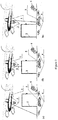
Fig. 2 depicts embodiments of the present invention. The following reference numerals are used: tethered unmanned aerial vehicle (tethered UAV) 1, charger andcontrol device 2, camera(s) 3;ground markers 4 androbot markers 5; and a natural marker depicted as abush 6. - The present invention provides a centralized robot control system and increases accuracy in determining robot coordinates (spatial and angular).
- The use of tethered platforms with surveillance devices which can be operated in three different modes (autogyro mode, wind motor mode, helicopter mode) provides effective robot coordination based on using robot tracking devices positioned at masts or aerial vehicles over the monitored area and monitoring the environment thereof, including natural and artificial markers.
- The combined operation in different modes complements each mode and compensates for drawbacks thereof.
- The solution is illustrated in
Fig. 2 , showing three exemplary embodiments (a, b, c) of the disclosed system. Fixedly mounted cameras covering the entire lower hemisphere are mounted on a suspended platform. Such arrangement is cheaper than using one adjustable camera, while a wired communications channel (fiber-optic or twisted pair) is reliable and high-capacity. Multiple cameras can be arranged on the tethered platform and on the suspender thereof at a required low altitude. The tethered platforms are attached to the ground via a cable (Fig. 2a ), tethered to the energy storage and supply device via a cable (Fig. 2b ), or attached directly to one of the robots in the monitored area (Fig. 2c ). - Energy can also be generated by solar panels mounted on the tethered platform, on the ground, or on the robots.
- In the disclosed solution, relative (differential) video positioning of the robots can be arranged with respect to the area or with respect to the aerial vehicle (or mast). Coordinates of the surveillance UAV may not be necessary to coordinate robot operation from the aerial vehicle (or mast). The invention can provide precise relative positioning of robots with respect to 3 or more special markers, fixed terrestrial objects, and other terrestrial robots.
- Accurate UAV coordinates do not guarantee providing accurate coordinates of terrestrial robots. However, such UAV coordinates (position and orientation thereof) can be required for correcting projection distortions on the obtained images.
- The present invention provides passive video surveillance in both natural and artificial light. The all-weather capability is provided by infrared and radar sight, by passive reflectors and active infrared markers, by infrared LEDs, etc.
- The use of several surveillance cameras over the monitored area (in various combinations of fixed cameras and cameras arranged on tethered high-altitude platforms) provides increased reliability and stereoscopic positioning accuracy, and eliminates blind spots (e.g., behind trees and under tree branches).
- Markers easily distinguishable from above can be placed on the robot, on the charger thereof, and on the ground.
- The central unit receiving all data from all tracking devices determines coordinates and orientation of the at least one controlled robot (both relative (differential) video positioning of the robot with respect to the area and with respect to tracking devices (cameras)) and, if necessary, determines coordinates and orientation of the tracking devices. Said unit is configured for transmitting control commands and signals (including RF signals) to the robots, tracking devices, and chargers, further providing the possibility of exchanging control and data signals among said devices.
- When multiple robots are used, the centralized coordination thereof is simple: the cameras see all robots at the same time, and a unified computer system receiving said data provides coordination of the mutual movement of the robots. Boundaries for the operating area (e.g. mowing boundaries for a lawnmower robot) can be set by specifying (e.g., using a mouse cursor or by drawing with a stylus or user's finger on a touch screen) boundaries on the computer system screen showing an image of the area.
- The disclosed system is operated as follows: initially, at least one robot is placed in the monitored area (e.g., on a lawn). Tracking devices (one or more cameras) mounted on aerial vehicles or masts are arranged above the monitored area prior to starting robot operation, wherein positions and height at which the devices are suspended are selected to cover the entire monitored area.
- In another example, the tracking device at the start of the operation process is located on the ground or on one of the robots; then, during operation, the device can take flight, fly or land on masts for tracking robots in the monitored area.
- The devices for tracking suspended platforms can be placed on the ground or on the robots, thus providing determination of mutual position and orientation between tracking devices and robots, and further allowing to determine the robot rotation angle more accurately and to determine robot position in camera blind spots (under canopies and trees) by performing orientation based on canopy surfaces and tree leaves visible above the robot.
- Furthermore, other spectral regions can be used instead of the visible signal. In this case, the signal is not necessarily natural and can be generated by a robot or by a device arranged on the camera or at a different point in space. Other useable signals include audio signals, ultrasound signals, radar signals, as well as sensors and markers such as olfactory or chemical signals or radioactivity slightly above the ambient level (e.g., silicon slabs).
- The object is solved by the disclosed method for navigating and joint coordinating one or more robots positioned in a monitored area by routing each robot based on data comprising coordinates of obstacles, of the processed area boundaries, of the monitored area boundaries, and of all robots in said area. In order to provide operation of robots in the monitored area, especially in sections of the monitored area where the signal from GPS satellites is either re-reflected or suppressed, devices for tracking robots in the monitored area and surveying the environment thereof are positioned on one or more tethered platforms above the monitored area prior to starting robot operation. The tracking devices are natural or artificial markers configured for transmitting data regarding the monitored area and objects present therein to each or some of the robots in said area. Based on the data from tracking devices, each or some robots provide determination of coordinates of obstacles, of the processed area boundaries, of the monitored area boundaries, and of all robots used in said area; furthermore, control signals are exchanged between the tracking device and the automated devices in the monitored area in order to establish mutual coordination. The method is characterized in that at least one suspended platform is a rotor device configured for operation in the following modes: autogyro mode, driven by the oncoming air stream; wind motor mode, powered by the oncoming wind, and helicopter mode, powered by a terrestrial charger.
- Therefore, when wind is present and area processing is not required, the suspended platform operates in the wind motor mode, charging the batteries. When wind is present and area processing is required, the suspended platform operates in the autogyro mode or in the combined autogyro and wind motor mode, charging the batteries. When area processing is required in zero-wind conditions, the suspended platform operates in the helicopter mode powered by the batteries. The system comprises a central computing unit arranged on the suspended platform, or on the ground, or on the charging device, or on the robot, the unit configured for determining coordinates, determining orientation of system elements, and forming control commands based on data received from all devices described hereinabove.
- The present invention provides a centralized robot control system and increases accuracy in determining robot coordinates (spatial and angular).
- The use of tethered platforms with surveillance devices which can be operated in three different modes (autogyro mode, wind motor mode, helicopter mode) provides effective robot coordination based on using robot tracking devices positioned at masts or aerial vehicles over the monitored area and monitoring the environment thereof, including natural and artificial markers.
- The combined operation in different modes complements each mode and compensates for drawbacks thereof.
- The method is illustrated in
Fig. 2 , showing three exemplary embodiments (a, b, c) of the disclosed method. Fixedly mounted cameras covering the entire lower hemisphere are mounted on a suspended platform. Such arrangement is cheaper than using one adjustable camera, while a wired communications channel (fiber-optic or twisted pair) is reliable and high-capacity. Multiple cameras can be arranged on the tethered platform and on the suspender thereof at a required low altitude. The tethered platforms are attached to the ground via a cable (Fig. 2a ), tethered to the energy storage and supply device via a cable (Fig. 2b ), or attached directly to one of the robots in the monitored area (Fig. 2c ). - Energy can also be generated by solar panels mounted on the tethered platform, on the ground, or on the robots.
- In the disclosed solution, relative (differential) video positioning of the robots can be arranged with respect to the area or with respect to the aerial vehicle (or mast). Coordinates of the surveillance UAV may not be necessary to coordinate robot operation from the aerial vehicle (or mast). The invention can provide precise relative positioning of robots with respect to 3 or more special markers, fixed terrestrial objects, and other terrestrial robots.
- Accurate UAV coordinates do not guarantee providing accurate coordinates of terrestrial robots. However, such UAV coordinates (position and orientation thereof) can be required for correcting projection distortions on the obtained images.
- The present invention provides passive video surveillance in both natural and artificial light. The all-weather capability is provided by infrared and radar sight, by passive reflectors and active infrared markers, by infrared LEDs, etc.
- The use of several surveillance cameras over the monitored area (in various combinations of fixed cameras and cameras arranged on tethered high-altitude platforms) provides increased reliability and stereoscopic positioning accuracy, and eliminates blind spots (e.g., behind trees and under tree branches).
- Markers easily distinguishable from above can be placed on the robot, on the charger thereof, and on the ground.
- The central unit receiving all data from all tracking devices determines coordinates and orientation of the at least one controlled robot (both relative (differential) video positioning of the robot with respect to the area and with respect to tracking devices (cameras)) and, if necessary, determines coordinates and orientation of the tracking devices. Said unit is configured for transmitting control commands and signals (including RF signals) to the robots, tracking devices, and chargers, further providing the possibility of exchanging control and data signals among said devices.
- When multiple robots are used, the centralized coordination thereof is simple: the cameras see all robots at the same time, and a unified computer system receiving said data provides coordination of the mutual movement of the robots. Boundaries for the operating area (e.g. mowing boundaries for a lawnmower robot) can be set by specifying (e.g., using a mouse cursor or by drawing with a stylus or user's finger on a touch screen) boundaries on the computer system screen showing an image of the area.
- The disclosed system is operated as follows: initially, at least one robot is placed in the monitored area (e.g., on a lawn). Tracking devices (one or more cameras) mounted on aerial vehicles or masts are arranged above the monitored area prior to starting robot operation, wherein positions and height at which the devices are suspended are selected to cover the entire monitored area.
- In another example, the tracking device at the start of the operation process is located on the ground or on one of the robots; then, during operation, the device can take flight, fly or land on masts for tracking robots in the monitored area.
- The devices for tracking suspended platforms can be placed on the ground or on the robots, thus providing determination of mutual position and orientation between tracking devices and robots, and further allowing to determine the robot rotation angle more accurately and to determine robot position in camera blind spots (under canopies and trees) by performing orientation based on canopy surfaces and tree leaves visible above the robot.
- Furthermore, other spectral regions can be used instead of the visible signal. In this case, the signal is not necessarily natural and can be generated by a robot or by a device arranged on the camera or at a different point in space. Other useable signals include audio signals, ultrasound signals, radar signals, as well as sensors and markers such as olfactory or chemical signals or radioactivity slightly above the ambient level (e.g., silicon slabs).
- The surveillance system can detect obstacles or moving objects and can determine grass height and quality of lawn mowing. The system is simple in implementation and inexpensive.
- The present system can be used with a wide variety of robots: automated lawnmowers, indoor cleaning robots, tractors, snowplows, garbage removal and street flushing vehicles, transporting vehicles for transporting people and goods, agricultural vehicles, municipal vehicles, transport vehicles, etc. The present system can be used with robots utilized on other planets, e.g. with Mars rovers.
Claims (8)
- A system for navigating and joint coordinating one or more robots positioned in a monitored area, the system comprising one or more suspended tethered platforms (1), one or more robot tracking devices (3) mounted on said suspended tethered platforms (1), natural or artificial markers (4, 5), a central unit (2) configured to receive data from said robot tracking devices (3) mounted on said suspended tethered platforms (1), said central unit (2) configured for determining coordinates and orientation of said robots, determining orientation of system elements, and forming control commands based on data received from said robot tracking devices (3), the system characterized in that at least one of said suspended tethered platforms (1) is a rotor device configured for operation in the following modes:a) autogyro, driven by the oncoming air stream;b) wind motor, powered by the oncoming wind, andc) helicopter, powered by a terrestrial charger .
- The system according to claim 1, characterized in that the at least one of said suspended tethered platforms (1) is connectable to a charging device (2) or to one of said robots by a cable for receiving energy therefrom and transferring energy thereto.
- The system according to claim 1, further comprising at least one upper hemisphere tracking device mountable on the surface of the monitored area or on one of said robots and configured for receiving data from the central unit (2) and for transferring data thereto.
- The system according to claim 1, further comprising at least one device for converting solar energy into electrical energy, the device positioned on the at least one of said suspended tethered platforms (1) and/or positionable on one of said robots and/or positionable on the surface of the monitored area.
- The system according to claim 4, characterized in that the device for converting solar energy is configured for transferring energy to said charging device (2) for charging batteries of the one of said robots and/or the at least one of said supended tethered platforms (1) in the helicopter flight mode.
- The system according to claim 1, characterized in that the at least one of said suspended tethered platforms (1) is configured for transferring energy generated in the wind motor mode to an energy storage device arranged on the at least one of said suspended tethered platform (1) and/or to one of said robots and/or to the charging device (2) for further use in the helicopter flight mode.
- The system according to claim 1, characterized in that the rotor device can be used as a security drone for home or garden.
- A method for navigating and joint coordinating one or more robots positioned in a monitored area, the method including the use of the system of any one of claims 1 to 7, wherein the rotor device is switched toa. the wind motor mode, charging batteries when wind is present and no area processing required,b. the autogyro mode or a combined autogyro and wind motor mode, charging batteries when wind is present and area processing is required,c. the helicopter motor mode powered by batteries when area processing is required in zero-wind conditions.
Applications Claiming Priority (3)
| Application Number | Priority Date | Filing Date | Title |
|---|---|---|---|
| RU2015121583A RU2691788C2 (en) | 2015-06-05 | 2015-06-05 | Method for coordination of ground-based mobile automated devices using single centralized control system |
| RU2015121582A RU2015121582A (en) | 2015-06-05 | 2015-06-05 | SYSTEM FOR COORDINATION OF LAND MOBILE AUTOMATED DEVICES |
| PCT/RU2015/000773 WO2016195532A1 (en) | 2015-06-05 | 2015-11-13 | System and method for coordinating terrestrial mobile automated devices |
Publications (3)
| Publication Number | Publication Date |
|---|---|
| EP3300842A1 EP3300842A1 (en) | 2018-04-04 |
| EP3300842A4 EP3300842A4 (en) | 2019-03-20 |
| EP3300842B1 true EP3300842B1 (en) | 2021-03-03 |
Family
ID=57441037
Family Applications (1)
| Application Number | Title | Priority Date | Filing Date |
|---|---|---|---|
| EP15894383.7A Not-in-force EP3300842B1 (en) | 2015-06-05 | 2015-11-13 | System and method for coordinating terrestrial mobile automated devices |
Country Status (3)
| Country | Link |
|---|---|
| US (1) | US20180329412A1 (en) |
| EP (1) | EP3300842B1 (en) |
| WO (1) | WO2016195532A1 (en) |
Families Citing this family (6)
| Publication number | Priority date | Publication date | Assignee | Title |
|---|---|---|---|---|
| US11086025B2 (en) * | 2015-08-13 | 2021-08-10 | Propeller Aerobotics Pty Ltd | Integrated visual geo-referencing target unit and method of operation |
| US20190056738A1 (en) * | 2017-08-18 | 2019-02-21 | Aptiv Technologies Limited | Navigation system |
| US11560226B2 (en) * | 2019-05-07 | 2023-01-24 | George Miller | Drone airstation method and system |
| CN114616972B (en) * | 2020-12-09 | 2026-03-27 | 南京泉峰科技有限公司 | Smart lawnmowers and smart lawnmower systems |
| CN114945882A (en) * | 2020-12-10 | 2022-08-26 | 南京泉峰科技有限公司 | Intelligent mower and intelligent mowing system |
| CN114056555B (en) * | 2021-11-16 | 2023-10-31 | 西安应用光学研究所 | GPS/Beidou-free tethered rotor automatic fixed-point lifting platform and control method |
Family Cites Families (5)
| Publication number | Priority date | Publication date | Assignee | Title |
|---|---|---|---|---|
| US6990406B2 (en) * | 2002-07-22 | 2006-01-24 | California Institute Of Technology | Multi-agent autonomous system |
| RU2012147923A (en) * | 2012-11-12 | 2014-05-20 | Общество с ограниченной ответственностью "ТРАНЗИСТ ВИДЕО" | METHOD FOR NAVIGATION AND JOINT COORDINATION OF AUTOMATED DEVICES |
| RU131276U1 (en) * | 2012-11-12 | 2013-08-20 | Общество с ограниченной ответственностью "ТРАНЗИСТ ВИДЕО" | DEVICE FOR COORDINATION OF AUTOMATED DEVICES |
| US9126682B2 (en) * | 2013-09-16 | 2015-09-08 | Google Inc. | Methods and systems for transitioning an aerial vehicle between hover flight and crosswind flight |
| CA2930849C (en) * | 2013-11-20 | 2022-02-08 | Rowbot Systems Llc | Robotic platform and method for performing multiple functions in agricultural systems |
-
2015
- 2015-11-13 US US15/576,859 patent/US20180329412A1/en not_active Abandoned
- 2015-11-13 EP EP15894383.7A patent/EP3300842B1/en not_active Not-in-force
- 2015-11-13 WO PCT/RU2015/000773 patent/WO2016195532A1/en not_active Ceased
Non-Patent Citations (1)
| Title |
|---|
| None * |
Also Published As
| Publication number | Publication date |
|---|---|
| EP3300842A1 (en) | 2018-04-04 |
| WO2016195532A1 (en) | 2016-12-08 |
| EP3300842A4 (en) | 2019-03-20 |
| US20180329412A1 (en) | 2018-11-15 |
Similar Documents
| Publication | Publication Date | Title |
|---|---|---|
| US12233859B2 (en) | Apparatus and methods for obstacle detection | |
| CN115202401B (en) | Flight path determination | |
| EP3519905B1 (en) | Drop-off location planning for delivery vehicle | |
| KR102229095B1 (en) | UAV operation method and device | |
| EP3300842A1 (en) | System and method for coordinating terrestrial mobile automated devices | |
| US9791866B2 (en) | Autonomous cargo delivery system | |
| US20200026720A1 (en) | Construction and update of elevation maps | |
| EP3119178B1 (en) | Method and system for navigating an agricultural vehicle on a land area | |
| US20170329351A1 (en) | Apparatus-assisted sensor data collection | |
| US20200117210A1 (en) | Auto-Exploration Control of a Robotic Vehicle | |
| US20180046177A1 (en) | Motion Sensing Flight Control System Based on Smart Terminal and Terminal Equipment | |
| US20180005534A1 (en) | Autonomous navigation of an unmanned aerial vehicle | |
| EP3761136B1 (en) | Control device, mobile body, and program | |
| KR20160082773A (en) | Drone for aviation disaster prevention | |
| CN104320208A (en) | A method of aerial radio monitoring | |
| WO2021159249A1 (en) | Route planning method and device, and storage medium | |
| JP2025083433A (en) | Flying object, processor, flight control method, program, and flight auxiliary facility | |
| CN114756050A (en) | Automatic cruise system applied to unmanned aerial vehicle remote sensing scene | |
| CN109213186B (en) | Unmanned aerial vehicle spraying operation method and device and unmanned aerial vehicle | |
| CN212951114U (en) | A UAV device and system for power surveying | |
| RU2691788C2 (en) | Method for coordination of ground-based mobile automated devices using single centralized control system | |
| CN217932506U (en) | Automatic cruise system applied to unmanned aerial vehicle remote sensing scene | |
| Ehrenfeld et al. | Visual navigation for airborne control of ground robots from tethered platform: creation of the first prototype | |
| Raj | Aerial Sensing Platform for Greenhouses | |
| Sagala et al. | Enhancing Agricultural Pesticide Application Through a Custom-Built Hexacopter Equipped with Advanced Control and Navigation Systems |
Legal Events
| Date | Code | Title | Description |
|---|---|---|---|
| STAA | Information on the status of an ep patent application or granted ep patent |
Free format text: STATUS: THE INTERNATIONAL PUBLICATION HAS BEEN MADE |
|
| PUAI | Public reference made under article 153(3) epc to a published international application that has entered the european phase |
Free format text: ORIGINAL CODE: 0009012 |
|
| STAA | Information on the status of an ep patent application or granted ep patent |
Free format text: STATUS: REQUEST FOR EXAMINATION WAS MADE |
|
| 17P | Request for examination filed |
Effective date: 20171228 |
|
| AK | Designated contracting states |
Kind code of ref document: A1 Designated state(s): AL AT BE BG CH CY CZ DE DK EE ES FI FR GB GR HR HU IE IS IT LI LT LU LV MC MK MT NL NO PL PT RO RS SE SI SK SM TR |
|
| AX | Request for extension of the european patent |
Extension state: BA ME |
|
| DAV | Request for validation of the european patent (deleted) | ||
| DAX | Request for extension of the european patent (deleted) | ||
| A4 | Supplementary search report drawn up and despatched |
Effective date: 20190218 |
|
| RIC1 | Information provided on ipc code assigned before grant |
Ipc: G05D 1/00 20060101ALI20190212BHEP Ipc: G05D 1/08 20060101ALI20190212BHEP Ipc: B64C 39/02 20060101ALI20190212BHEP Ipc: G05D 3/00 20060101ALI20190212BHEP Ipc: B25J 13/08 20060101AFI20190212BHEP Ipc: B25J 19/00 20060101ALI20190212BHEP Ipc: G05D 1/02 20060101ALI20190212BHEP |
|
| STAA | Information on the status of an ep patent application or granted ep patent |
Free format text: STATUS: EXAMINATION IS IN PROGRESS |
|
| 17Q | First examination report despatched |
Effective date: 20200120 |
|
| GRAP | Despatch of communication of intention to grant a patent |
Free format text: ORIGINAL CODE: EPIDOSNIGR1 |
|
| STAA | Information on the status of an ep patent application or granted ep patent |
Free format text: STATUS: GRANT OF PATENT IS INTENDED |
|
| INTG | Intention to grant announced |
Effective date: 20201006 |
|
| GRAS | Grant fee paid |
Free format text: ORIGINAL CODE: EPIDOSNIGR3 |
|
| GRAA | (expected) grant |
Free format text: ORIGINAL CODE: 0009210 |
|
| STAA | Information on the status of an ep patent application or granted ep patent |
Free format text: STATUS: THE PATENT HAS BEEN GRANTED |
|
| AK | Designated contracting states |
Kind code of ref document: B1 Designated state(s): AL AT BE BG CH CY CZ DE DK EE ES FI FR GB GR HR HU IE IS IT LI LT LU LV MC MK MT NL NO PL PT RO RS SE SI SK SM TR |
|
| REG | Reference to a national code |
Ref country code: GB Ref legal event code: FG4D |
|
| RIN1 | Information on inventor provided before grant (corrected) |
Inventor name: KUPERVASSER, OLEG YUREVICH |
|
| REG | Reference to a national code |
Ref country code: AT Ref legal event code: REF Ref document number: 1366700 Country of ref document: AT Kind code of ref document: T Effective date: 20210315 Ref country code: CH Ref legal event code: EP |
|
| REG | Reference to a national code |
Ref country code: DE Ref legal event code: R096 Ref document number: 602015066511 Country of ref document: DE |
|
| REG | Reference to a national code |
Ref country code: IE Ref legal event code: FG4D |
|
| REG | Reference to a national code |
Ref country code: LT Ref legal event code: MG9D |
|
| PG25 | Lapsed in a contracting state [announced via postgrant information from national office to epo] |
Ref country code: NO Free format text: LAPSE BECAUSE OF FAILURE TO SUBMIT A TRANSLATION OF THE DESCRIPTION OR TO PAY THE FEE WITHIN THE PRESCRIBED TIME-LIMIT Effective date: 20210603 Ref country code: LT Free format text: LAPSE BECAUSE OF FAILURE TO SUBMIT A TRANSLATION OF THE DESCRIPTION OR TO PAY THE FEE WITHIN THE PRESCRIBED TIME-LIMIT Effective date: 20210303 Ref country code: FI Free format text: LAPSE BECAUSE OF FAILURE TO SUBMIT A TRANSLATION OF THE DESCRIPTION OR TO PAY THE FEE WITHIN THE PRESCRIBED TIME-LIMIT Effective date: 20210303 Ref country code: GR Free format text: LAPSE BECAUSE OF FAILURE TO SUBMIT A TRANSLATION OF THE DESCRIPTION OR TO PAY THE FEE WITHIN THE PRESCRIBED TIME-LIMIT Effective date: 20210604 Ref country code: HR Free format text: LAPSE BECAUSE OF FAILURE TO SUBMIT A TRANSLATION OF THE DESCRIPTION OR TO PAY THE FEE WITHIN THE PRESCRIBED TIME-LIMIT Effective date: 20210303 Ref country code: BG Free format text: LAPSE BECAUSE OF FAILURE TO SUBMIT A TRANSLATION OF THE DESCRIPTION OR TO PAY THE FEE WITHIN THE PRESCRIBED TIME-LIMIT Effective date: 20210603 |
|
| REG | Reference to a national code |
Ref country code: NL Ref legal event code: MP Effective date: 20210303 |
|
| REG | Reference to a national code |
Ref country code: AT Ref legal event code: MK05 Ref document number: 1366700 Country of ref document: AT Kind code of ref document: T Effective date: 20210303 |
|
| PG25 | Lapsed in a contracting state [announced via postgrant information from national office to epo] |
Ref country code: SE Free format text: LAPSE BECAUSE OF FAILURE TO SUBMIT A TRANSLATION OF THE DESCRIPTION OR TO PAY THE FEE WITHIN THE PRESCRIBED TIME-LIMIT Effective date: 20210303 Ref country code: PL Free format text: LAPSE BECAUSE OF FAILURE TO SUBMIT A TRANSLATION OF THE DESCRIPTION OR TO PAY THE FEE WITHIN THE PRESCRIBED TIME-LIMIT Effective date: 20210303 Ref country code: RS Free format text: LAPSE BECAUSE OF FAILURE TO SUBMIT A TRANSLATION OF THE DESCRIPTION OR TO PAY THE FEE WITHIN THE PRESCRIBED TIME-LIMIT Effective date: 20210303 Ref country code: LV Free format text: LAPSE BECAUSE OF FAILURE TO SUBMIT A TRANSLATION OF THE DESCRIPTION OR TO PAY THE FEE WITHIN THE PRESCRIBED TIME-LIMIT Effective date: 20210303 |
|
| PG25 | Lapsed in a contracting state [announced via postgrant information from national office to epo] |
Ref country code: NL Free format text: LAPSE BECAUSE OF FAILURE TO SUBMIT A TRANSLATION OF THE DESCRIPTION OR TO PAY THE FEE WITHIN THE PRESCRIBED TIME-LIMIT Effective date: 20210303 |
|
| PG25 | Lapsed in a contracting state [announced via postgrant information from national office to epo] |
Ref country code: SM Free format text: LAPSE BECAUSE OF FAILURE TO SUBMIT A TRANSLATION OF THE DESCRIPTION OR TO PAY THE FEE WITHIN THE PRESCRIBED TIME-LIMIT Effective date: 20210303 Ref country code: AT Free format text: LAPSE BECAUSE OF FAILURE TO SUBMIT A TRANSLATION OF THE DESCRIPTION OR TO PAY THE FEE WITHIN THE PRESCRIBED TIME-LIMIT Effective date: 20210303 Ref country code: EE Free format text: LAPSE BECAUSE OF FAILURE TO SUBMIT A TRANSLATION OF THE DESCRIPTION OR TO PAY THE FEE WITHIN THE PRESCRIBED TIME-LIMIT Effective date: 20210303 Ref country code: CZ Free format text: LAPSE BECAUSE OF FAILURE TO SUBMIT A TRANSLATION OF THE DESCRIPTION OR TO PAY THE FEE WITHIN THE PRESCRIBED TIME-LIMIT Effective date: 20210303 |
|
| PG25 | Lapsed in a contracting state [announced via postgrant information from national office to epo] |
Ref country code: IS Free format text: LAPSE BECAUSE OF FAILURE TO SUBMIT A TRANSLATION OF THE DESCRIPTION OR TO PAY THE FEE WITHIN THE PRESCRIBED TIME-LIMIT Effective date: 20210703 Ref country code: SK Free format text: LAPSE BECAUSE OF FAILURE TO SUBMIT A TRANSLATION OF THE DESCRIPTION OR TO PAY THE FEE WITHIN THE PRESCRIBED TIME-LIMIT Effective date: 20210303 Ref country code: RO Free format text: LAPSE BECAUSE OF FAILURE TO SUBMIT A TRANSLATION OF THE DESCRIPTION OR TO PAY THE FEE WITHIN THE PRESCRIBED TIME-LIMIT Effective date: 20210303 Ref country code: PT Free format text: LAPSE BECAUSE OF FAILURE TO SUBMIT A TRANSLATION OF THE DESCRIPTION OR TO PAY THE FEE WITHIN THE PRESCRIBED TIME-LIMIT Effective date: 20210705 |
|
| REG | Reference to a national code |
Ref country code: DE Ref legal event code: R097 Ref document number: 602015066511 Country of ref document: DE |
|
| PLBE | No opposition filed within time limit |
Free format text: ORIGINAL CODE: 0009261 |
|
| STAA | Information on the status of an ep patent application or granted ep patent |
Free format text: STATUS: NO OPPOSITION FILED WITHIN TIME LIMIT |
|
| PG25 | Lapsed in a contracting state [announced via postgrant information from national office to epo] |
Ref country code: AL Free format text: LAPSE BECAUSE OF FAILURE TO SUBMIT A TRANSLATION OF THE DESCRIPTION OR TO PAY THE FEE WITHIN THE PRESCRIBED TIME-LIMIT Effective date: 20210303 Ref country code: ES Free format text: LAPSE BECAUSE OF FAILURE TO SUBMIT A TRANSLATION OF THE DESCRIPTION OR TO PAY THE FEE WITHIN THE PRESCRIBED TIME-LIMIT Effective date: 20210303 Ref country code: DK Free format text: LAPSE BECAUSE OF FAILURE TO SUBMIT A TRANSLATION OF THE DESCRIPTION OR TO PAY THE FEE WITHIN THE PRESCRIBED TIME-LIMIT Effective date: 20210303 |
|
| PGFP | Annual fee paid to national office [announced via postgrant information from national office to epo] |
Ref country code: FR Payment date: 20211119 Year of fee payment: 7 Ref country code: GB Payment date: 20211029 Year of fee payment: 7 Ref country code: DE Payment date: 20211126 Year of fee payment: 7 |
|
| 26N | No opposition filed |
Effective date: 20211206 |
|
| PG25 | Lapsed in a contracting state [announced via postgrant information from national office to epo] |
Ref country code: SI Free format text: LAPSE BECAUSE OF FAILURE TO SUBMIT A TRANSLATION OF THE DESCRIPTION OR TO PAY THE FEE WITHIN THE PRESCRIBED TIME-LIMIT Effective date: 20210303 |
|
| PG25 | Lapsed in a contracting state [announced via postgrant information from national office to epo] |
Ref country code: IT Free format text: LAPSE BECAUSE OF FAILURE TO SUBMIT A TRANSLATION OF THE DESCRIPTION OR TO PAY THE FEE WITHIN THE PRESCRIBED TIME-LIMIT Effective date: 20210303 |
|
| PG25 | Lapsed in a contracting state [announced via postgrant information from national office to epo] |
Ref country code: IS Free format text: LAPSE BECAUSE OF FAILURE TO SUBMIT A TRANSLATION OF THE DESCRIPTION OR TO PAY THE FEE WITHIN THE PRESCRIBED TIME-LIMIT Effective date: 20210703 |
|
| PG25 | Lapsed in a contracting state [announced via postgrant information from national office to epo] |
Ref country code: MC Free format text: LAPSE BECAUSE OF FAILURE TO SUBMIT A TRANSLATION OF THE DESCRIPTION OR TO PAY THE FEE WITHIN THE PRESCRIBED TIME-LIMIT Effective date: 20210303 |
|
| REG | Reference to a national code |
Ref country code: CH Ref legal event code: PL |
|
| PG25 | Lapsed in a contracting state [announced via postgrant information from national office to epo] |
Ref country code: LU Free format text: LAPSE BECAUSE OF NON-PAYMENT OF DUE FEES Effective date: 20211113 Ref country code: BE Free format text: LAPSE BECAUSE OF NON-PAYMENT OF DUE FEES Effective date: 20211130 |
|
| REG | Reference to a national code |
Ref country code: BE Ref legal event code: MM Effective date: 20211130 |
|
| PG25 | Lapsed in a contracting state [announced via postgrant information from national office to epo] |
Ref country code: LI Free format text: LAPSE BECAUSE OF NON-PAYMENT OF DUE FEES Effective date: 20211130 Ref country code: CH Free format text: LAPSE BECAUSE OF NON-PAYMENT OF DUE FEES Effective date: 20211130 |
|
| PG25 | Lapsed in a contracting state [announced via postgrant information from national office to epo] |
Ref country code: IE Free format text: LAPSE BECAUSE OF NON-PAYMENT OF DUE FEES Effective date: 20211113 |
|
| PG25 | Lapsed in a contracting state [announced via postgrant information from national office to epo] |
Ref country code: HU Free format text: LAPSE BECAUSE OF FAILURE TO SUBMIT A TRANSLATION OF THE DESCRIPTION OR TO PAY THE FEE WITHIN THE PRESCRIBED TIME-LIMIT; INVALID AB INITIO Effective date: 20151113 |
|
| REG | Reference to a national code |
Ref country code: DE Ref legal event code: R119 Ref document number: 602015066511 Country of ref document: DE |
|
| PG25 | Lapsed in a contracting state [announced via postgrant information from national office to epo] |
Ref country code: CY Free format text: LAPSE BECAUSE OF FAILURE TO SUBMIT A TRANSLATION OF THE DESCRIPTION OR TO PAY THE FEE WITHIN THE PRESCRIBED TIME-LIMIT Effective date: 20210303 |
|
| GBPC | Gb: european patent ceased through non-payment of renewal fee |
Effective date: 20221113 |
|
| PG25 | Lapsed in a contracting state [announced via postgrant information from national office to epo] |
Ref country code: GB Free format text: LAPSE BECAUSE OF NON-PAYMENT OF DUE FEES Effective date: 20221113 Ref country code: DE Free format text: LAPSE BECAUSE OF NON-PAYMENT OF DUE FEES Effective date: 20230601 |
|
| PG25 | Lapsed in a contracting state [announced via postgrant information from national office to epo] |
Ref country code: FR Free format text: LAPSE BECAUSE OF NON-PAYMENT OF DUE FEES Effective date: 20221130 |
|
| PG25 | Lapsed in a contracting state [announced via postgrant information from national office to epo] |
Ref country code: MK Free format text: LAPSE BECAUSE OF FAILURE TO SUBMIT A TRANSLATION OF THE DESCRIPTION OR TO PAY THE FEE WITHIN THE PRESCRIBED TIME-LIMIT Effective date: 20210303 |
|
| PG25 | Lapsed in a contracting state [announced via postgrant information from national office to epo] |
Ref country code: TR Free format text: LAPSE BECAUSE OF FAILURE TO SUBMIT A TRANSLATION OF THE DESCRIPTION OR TO PAY THE FEE WITHIN THE PRESCRIBED TIME-LIMIT Effective date: 20210303 |
|
| PG25 | Lapsed in a contracting state [announced via postgrant information from national office to epo] |
Ref country code: MT Free format text: LAPSE BECAUSE OF FAILURE TO SUBMIT A TRANSLATION OF THE DESCRIPTION OR TO PAY THE FEE WITHIN THE PRESCRIBED TIME-LIMIT Effective date: 20210303 |